the construction of metal flexible torsional coupling · the construction of metal flexible...
TRANSCRIPT
TRANSPORT PROBLEMS 2007
PROBLEMY TRANSPORTU Tom 2 Zeszyt 3
Aleksander KOWAL*, Krzysztof FILIPOWICZ Silesian University of Technology, Faculty of Mining and Geology, Institute of Mining Mechanisation
Akademicka st. 2, Gliwice 44-100, Poland
*Corresponding author. E-mail: [email protected]
THE CONSTRUCTION OF METAL FLEXIBLE TORSIONAL COUPLING
Summary. In working heavy machines, eg. in mining machines, builder′s and of road,
appear loads of dynamics and percussive. These loads demand usages in systems of
driving machines of flexible torsional coupling. In the elaboration one showed new
constructions of metal coupling, very flexible torsionally which one worked out in the
Institute of Mining Mechanization at the Silesian University of Technology.
KONSTRUKCJA METALOWYCH SPRZĘGIEŁ PODATNYCH SKRĘTNIE
Streszczenie. W cięŜkich maszynach roboczych, np. w maszynach górniczych,
budowlanych i drogowych, występują obciąŜenia dynamiczne i udarowe. ObciąŜenia te
wymagają stosowania w układach napędowych maszyn sprzęgieł podatnych skrętnie. W
opracowaniu pokazano nowe konstrukcje metalowych sprzęgieł bardzo podatnych
skrętnie, które opracowano w Instytucie Mechanizacji Górnictwa Politechniki Śląskiej.
1. INTRODUCTION
In effect of exploitive often one ascertains the emergency halt of the machine, due to the damage
of its elements as a result of the dynamic overworking. In the face of the above, it would be important
for the use in the system of driving machines, coupling about the large torsional susceptibility, letting
on a considerable diminishing of the influence of these unprofitable factors. To underline one ought to
the fact that the average number of dynamic extortions occurrence at the start eg. curry-comb
conveyors crosses 100 by rotation. Practical at present in the world flexible coupling in the driving
system complies only after the page of the high-speed drive, ie. among the driving engine and the
toothed gear, and this does not protect all the arrangement, and particularly of the toothed gear which
is situated directly in the working organ. Practical in the underground mining of the hydrokinetics
coupling are dear and exacting of the large exploitive culture. Instead flexible coupling with insertions
elastic or of elastomeric have a maximum angle of the relative twist carrying out several degrees,
which does not protect the driving arrangement before the surcharge, eg. at the start of the machine
and at the dynamic weight [1, 7, 8].
Till now in mining-machines are practical often on the entry of driving systems, between motor
and the drive, two coupling, namely so called elastic with insertions, of elastomeric or of polyurethane
and the hydrokinetics coupling. Such solutions are dear and complex constructively. Practical at
present coupling CST DBT characterize themselves with the complicated construction and complex
control systems, and their mechanism of action is based on work of the friction coupling.
74 A. Kowal, K. Filipowicz
Working conditions of driving practical systems in mining-machines, determine the usage in
systems of driving coupling about the large torsional susceptibility, resistant on the influence of
definite conditions of loads. The suitable torsional susceptibility of the coupling can assure solution
worked out in the Institute of Mining Mechanisation, Faculty of Mining and Geology at the Silesian
University of Technology [2, 3, 4, 5].
2. THE CONSTRUCTION OF THE METAL FLEXIBLE TORSIONAL COUPLING WITH
ONE THREAD CONNECTION
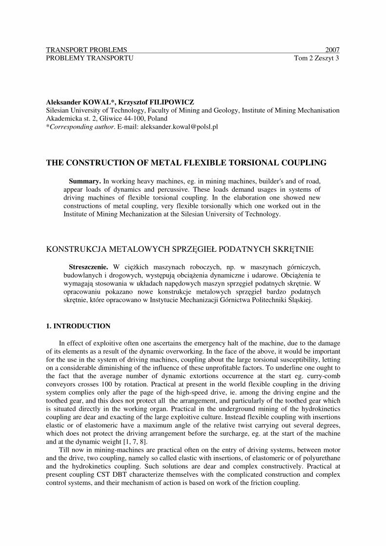
The creature of the activity of the coupling about the very large torsional (Fig. 1) susceptibility
consists in these that the torque transferred is from the active to passive by means of the mechanism of
the thread and movable shape connection , whereas one uses also the arrangement resilient –
extinguishing in the form of the set of disk springs (3). The thread mechanism one executes between
the outside threaded entrance- (1)shaft -for determining the active element of the coupling and with
the moving nut (2) which possesses notched on the cylindrical epidermis, splines (5). External grooves
of the nut are in the movable connection with the splines performed on the internal surface of the joint
casing (4) with the nave exit- (7), being a passive element of the coupling [3].
The resistance of the set of disk springs (3), during the rotary motion of the entrance-shaft, causes
the height of the storage-power towards the place on the thread of the helical mechanism. The height
of this power causes incrementing the torque, and when it will reach the value of the working moment
of the machine, beginsits rotary motion being simultaneously with the working traffic.
Temporary surcharges of the working machine causes the additional compression of resilient
elements, and unloading of the machine their distress. After the disconnection of the driving system,
the nut pressed by the spring returns towards the initial position on the entrance-shaft. At the proper
large initial wring of the spring and after the disconnection system, the nut comes back to the first
position.
The resilient element can consist of at will, situated packs of disk springs arranged into the set.
The selection of springs and their set depends only from founded characterization of the coupling. The
steering angle of elements of the coupling, under the nominal load between the entry and the exit, can
be large and carry out eg. the full turn of the entrance- (active)shaft before the exit-(passive) shaft will
begin the rotary motion.
Fig. 1. The scheme of the one-way- flexible torsional coupling, where: 1 – driveshaft with thread, 2 – the nut
with internal thread and the splines, 3 – disc springs set, 4 – cover with splines, 5 – mobile splined
coupling, 6 – left cover, 7 – output cover, 8 – cone bearings, 9 – thrust bearing, 10 – sealing ring, 11 –
jointing sleeve
Rys. 1. Schemat jednokierunkowego sprzęgła podatnego skrętnie, gdzie: 1 – wał wejściowy z gwintem, 2 –
nakrętka z gwintem wewnętrznym i wielowypustem, 3 – zespół spręŜyn talerzowych, 4 – obudowa z
wielowypustem, 5 – ruchowe połączenie wielowypustowe, 6 – pokrywa lewa, 7 – piasta wyjściowa, 8 –
łoŜyska stoŜkowe, 9 – łoŜysko wzdłuŜne, 10 – pierścień uszczelniający, 11 – tuleja połączeniowa
The construction of metal flexible torsional coupling 75
3. THE CONSTRUCTION OF THE METAL FLEXIBLE TORSIONAL COUPLING
WITH TWO THREADS MECHANISMS
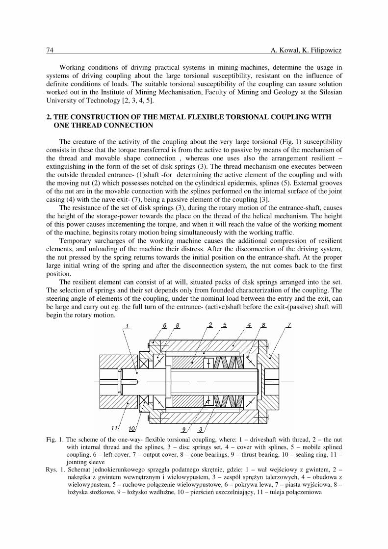
The second solution is the coupling introduced in Fig. 2, wherein the torque transferred is from
the active to passive by means of nuts with two threads mechanisms. Screwed connexions one
performs between the outside threaded entrance- (1) shaft and the nut (2) which possesses also thread
on the cylindrical epidermis. This external thread works in with the internal thread performed in the
casing (4). Both thread mechanisms differ with directions of the helix and jump. Threads about
different directions and jumps causes that at turns of the entrance-shaft, the nut moves for the
dependent value from jumps of these threads [4, 5].
In both solutions of coupling, jumps of multiple threads are on so much large that the angle of the
helix is greater from the angle of friction for materials of the screw and the nut.
Fig. 2. The example of torsional flexible coupling with two screws, where: 1 – driveshaft with thread, 2 – screw
nut with inside and outside thread, 3 – dished disc springs set, 4 – inner thread housing, 5 – inside thread,
6 – left cover, 7 – right cover, 8 – cone bearings, 9 – thrust bearing, 10 – sealing ring, 11 – jointing sleeve
Rys. 2. Przykład budowy sprzęgła podatnego skrętnie z dwoma gwintami, gdzie: 1 – wał wejściowy z gwintem,
2 – nakrętka z gwintem wewnętrznym i zewnętrznym, 3 – zespół spręŜyn talerzowych, 4 – obudowa z
gwintem wewnętrznym, 5 – gwint wewnętrzny, 6 – pokrywa prawa, 7 – pierścień regulacyjny, 8 –
łoŜyska stoŜkowe, 9 – łoŜysko wzdłuŜne, 10 – pierścień uszczelniający, 11 – tuleja połączeniowa
4. THE CONSTRUCTION OF THE METAL COUPLING OF SURCHARGE
In the Institute of Mining Mechanization at the Silesian University of Technology was constructed
and performed also, the prototype of the coupling of surcharge which is built completely from metal
and is also very flexible torsionally, and at the pronouncement overload the coupling it switches off ,
completely separating the active element from passive. Then the drive unit works almost so as in gear
margin. After the diminishing of the external load the coupling automatically joins (Fig. 3) [6].
Introduced coupling solves the problem of diminishing of the temporary overloads of the driving
system of the machine or the device during starts and the appeasement of dynamic loads during the
exploitation, and also breaks the flow of the power in the chance of the excessive overload which often
appears in systems of driving heavy machinery, eg. of mining and of road.
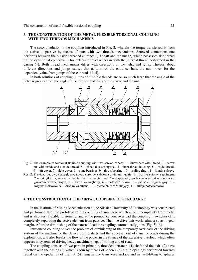
The coupling consists of two parts in principle, threaded entrance- (1) shaft and the exit- (2) nave
together with the casing (3) which is join by means of spheres (6) put in openings performed towards
radial on the epidermis of the nut (5) lying in one transverse surface and in well-fitting to spheres
76 A. Kowal, K. Filipowicz
grooves (4) performed inside casings (3). The nut (5) works in with performed thread on the entrance-
(1) shaft. At the rotary motion of the entrance- (1) shaft, the nut (5) moves toward the exit- (2) nave
clamps down on the set of springs (7) and deforms it. Spheres (6) stand from openings performed in
the nut. These juts of spheres are seated in grooves semicircular, performed in the casing (3) which is
joined with the exit- (2) nave.
In the chance of overload spheres advance from grooves in the casing and freely shift towards
circumferential outside the zone of grooves. If overload will diminish, then spheres in the gyral nut
after the definite turning angle will be pressed by accumulated energy in the set of disk springs (7) to
grooves and follows the renewed transfer of the torque by the coupling.
Fig. 3. Overloading coupling highly torsionally flexible, where: 1 – driveshaft with thread, 2 – coupling exit, 3 –
cover, 4 – row in the cover, 5 – a nut with balls nets, 6 – balls, 7 – springing-damping element, 8 – cone
bearings, 9 – thrust bearing, 10 – jointing sleeve, 11 – sealing ring
Rys. 3. Schemat sprzęgła przeciąŜeniowego o duŜej podatności skrętnej, gdzie: 1 – wał wejściowy z gwintem,
2 – piasta wyjściowa, 3 – obudowa, 4 – rowek w obudowie, 5 – nakrętka z gniazdami na kulki, 6 – kule,
7 – element spręŜysto-tłumiący, 8 – łoŜysko skośne, 9 – łoŜysko wzdłuŜne, 10 – tuleja połączeniowa,
11 – pierścień uszczelniający
5. THE SET OF DISK SPRINGS
To the metal coupling about the awaited torsional susceptibility, one understands the suitable
characterization of the set of springs which has for assignment the transfer of the variable dependent
load from the kind load of the working machine.
Foreseen axial loads generated by the helical mechanism of the coupling, are characterized with
considerable values of static powers as in dynamic, consequential from the character of the work of
the coupling. From here as resilient elements applied should be disk springs situated in different sets
depending on founded characterization of the coupling.
Advantages of disk springs, engaging in their use in proposed constructional form of the prototype
of the coupling, let on the possibility of the obtainment:
the lineal progressive dependent characterization from measurements and the chosen arrangement of
springs, the degressive non-linear characterization across the use of different sets of springs, placed in
suitable configuration packs, possibilities of the easy influence on resilient properties of the
arrangement by adding or the removal of single springs, the very large suppression of the own
arrangement of springs, the lack of the deformation and the slight waste at the nominal load, savings
of the place influent longways of the coupling, the large exploitive life time.
The construction of metal flexible torsional coupling 77
Disk springs and their measurements depending on the value of the load and the required
deformation, one understands from Polish norms: PN-73/M-80707 [10].
With the aim of the obtainment of the awaited torsional susceptibility of the metal coupling,
understands the suitable characterization of the set of disk springs. The required characterization of the
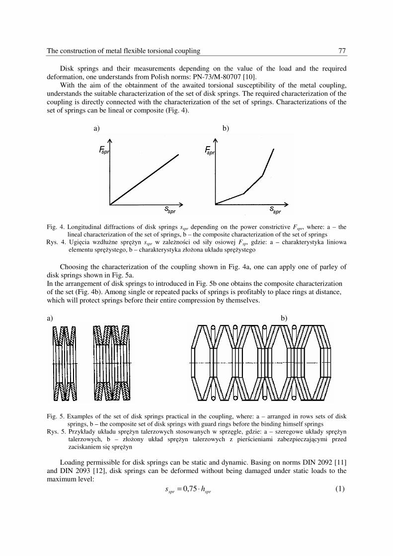
coupling is directly connected with the characterization of the set of springs. Characterizations of the
set of springs can be lineal or composite (Fig. 4).
a) b)
Fig. 4. Longitudinal diffractions of disk springs sspr depending on the power constrictive Fspr, where: a – the
lineal characterization of the set of springs, b – the composite characterization of the set of springs
Rys. 4. Ugięcia wzdłuŜne spręŜyn sspr w zaleŜności od siły osiowej Fsp, gdzie: a – charakterystyka liniowa
elementu spręŜystego, b – charakterystyka złoŜona układu spręŜystego
Choosing the characterization of the coupling shown in Fig. 4a, one can apply one of parley of
disk springs shown in Fig. 5a.
In the arrangement of disk springs to introduced in Fig. 5b one obtains the composite characterization
of the set (Fig. 4b). Among single or repeated packs of springs is profitably to place rings at distance,
which will protect springs before their entire compression by themselves.
a) b)
Fig. 5. Examples of the set of disk springs practical in the coupling, where: a – arranged in rows sets of disk
springs, b – the composite set of disk springs with guard rings before the binding himself springs
Rys. 5. Przykłady układu spręŜyn talerzowych stosowanych w sprzęgle, gdzie: a – szeregowe układy spręŜyn
talerzowych, b – złoŜony układ spręŜyn talerzowych z pierścieniami zabezpieczającymi przed
zaciskaniem się spręŜyn
Loading permissible for disk springs can be static and dynamic. Basing on norms DIN 2092 [11]
and DIN 2093 [12], disk springs can be deformed without being damaged under static loads to the
maximum level:
sprspr hs ⋅= 75,0 (1)
78 A. Kowal, K. Filipowicz
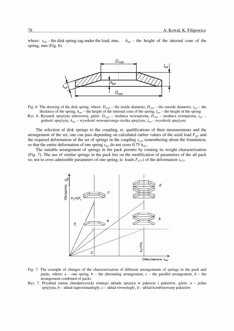
where: sspr - the disk spring sag under the load, mm, hspr - the height of the internal cone of the
spring, mm (Fig. 6).
Fig. 6. The drawing of the disk spring, where: Dwspr – the inside diameter, Dzspr – the outside diameter, tspr – the
thickness of the spring, hspr – the height of the internal cone of the spring, lspr – the height of the spring
Rys. 6. Rysunek spręŜyny talerzowej, gdzie: Dwspr – średnica wewnętrzna, Dzspr – średnica zewnętrzna, tspr –
grubość spręŜyny, hspr – wysokość wewnętrznego stoŜka spręŜyny, lspr – wysokość spręŜyny
The selection of disk springs to the coupling, ie. qualifications of their measurements and the
arrangement of the set, one can pass depending on calculated earlier values of the axial load Fspr and
the required deformation of the set of springs in the coupling szest remembering about the foundation,
so that the entire deformation of one spring sspr do not cross 0,75 hspr.
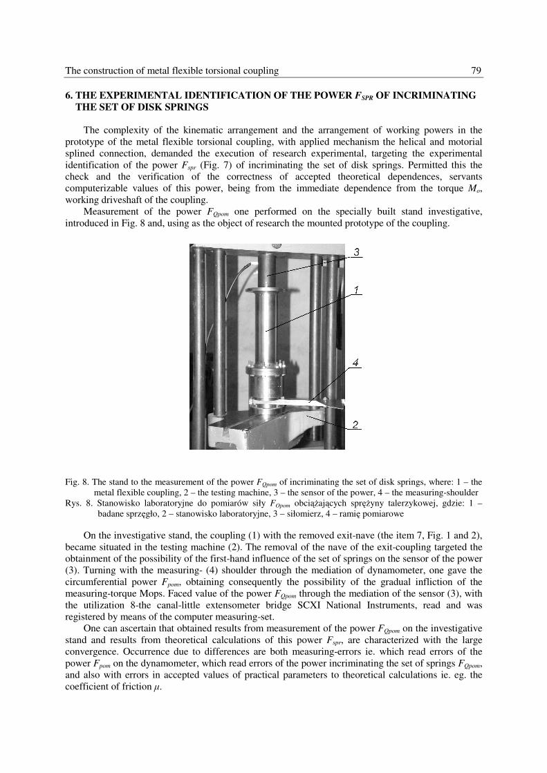
The suitable arrangement of springs in the pack permits by rotating its weight characterization
(Fig. 7). The use of similar springs in the pack lets on the modification of parameters of the all pack
so, not to cross admissible parameters of one spring, ie. loads Fn75.i of the deformation sn75.
Fig. 7. The example of changes of the characterization of different arrangements of springs in the pack and
packs, where: a – one spring, b – the alternating arrangement, c – the parallel arrangement, d – the
arrangement combined of packs
Rys. 7. Przykład zmian charakterystyki róŜnego układu spręŜyn w pakiecie i pakietów, gdzie: a – jedna
spręŜyna, b – układ naprzemianległy, c – układ równoległy, d – układ kombinowany pakietów
The construction of metal flexible torsional coupling 79
6. THE EXPERIMENTAL IDENTIFICATION OF THE POWER FSPR OF INCRIMINATING
THE SET OF DISK SPRINGS
The complexity of the kinematic arrangement and the arrangement of working powers in the
prototype of the metal flexible torsional coupling, with applied mechanism the helical and motorial
splined connection, demanded the execution of research experimental, targeting the experimental
identification of the power Fspr (Fig. 7) of incriminating the set of disk springs. Permitted this the
check and the verification of the correctness of accepted theoretical dependences, servants
computerizable values of this power, being from the immediate dependence from the torque Mo,
working driveshaft of the coupling.
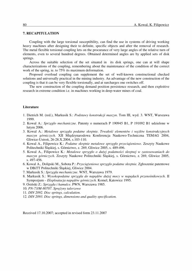
Measurement of the power FQpom one performed on the specially built stand investigative,
introduced in Fig. 8 and, using as the object of research the mounted prototype of the coupling.
Fig. 8. The stand to the measurement of the power FQpom of incriminating the set of disk springs, where: 1 – the
metal flexible coupling, 2 – the testing machine, 3 – the sensor of the power, 4 – the measuring-shoulder
Rys. 8. Stanowisko laboratoryjne do pomiarów siły FOpom obciąŜających spręŜyny talerzykowej, gdzie: 1 –
badane sprzęgło, 2 – stanowisko laboratoryjne, 3 – siłomierz, 4 – ramię pomiarowe
On the investigative stand, the coupling (1) with the removed exit-nave (the item 7, Fig. 1 and 2),
became situated in the testing machine (2). The removal of the nave of the exit-coupling targeted the
obtainment of the possibility of the first-hand influence of the set of springs on the sensor of the power
(3). Turning with the measuring- (4) shoulder through the mediation of dynamometer, one gave the
circumferential power Fpom, obtaining consequently the possibility of the gradual infliction of the
measuring-torque Mops. Faced value of the power FQpom through the mediation of the sensor (3), with
the utilization 8-the canal-little extensometer bridge SCXI National Instruments, read and was
registered by means of the computer measuring-set.
One can ascertain that obtained results from measurement of the power FQpom on the investigative
stand and results from theoretical calculations of this power Fspr, are characterized with the large
convergence. Occurrence due to differences are both measuring-errors ie. which read errors of the
power Fpom on the dynamometer, which read errors of the power incriminating the set of springs FQpom,
and also with errors in accepted values of practical parameters to theoretical calculations ie. eg. the
coefficient of friction µ.
80 A. Kowal, K. Filipowicz
7. RECAPITULATION
Coupling with the large torsional susceptibility, can find the use in systems of driving working
heavy machines after designing their to definite, specific objects and after the removal of research.
The metal flexible torsional coupling lets on the procurance of very large angles of the relative turn of
elements, even to several hundred degrees. Obtained determined angles are by applied sets of disk
springs.
Across the suitable selection of the set situated in its disk springs, one can at will shape
characterizations of the coupling, remembering about the maintenance of the condition of the correct
work of the spring, ie. to 75% its maximum deformation.
Proposed overload coupling can supplement the set of well-known constructional checked
solutions and universally practical in the mining industry. An advantage of the new construction of the
coupling is that it can be very flexible torsionally, and at surcharges one switches off.
The new construction of the coupling demand position persistence research, and then exploitive
research in extreme condition i.e. in machines working in deep-water mines of coal.
Literature
1. Dietrich M. (red.), Markusik S.: Podstawy konstrukcji maszyn. Tom III, wyd. 3. WNT, Warszawa
1999.
2. Kowal A.: Sprzęgło mechaniczne. Patenty o numerach P 190945 B1, P 191092 B1 udzielone w
lutym 2006.
3. Kowal A.: Metalowe sprzęgła podatne skrętnie. Trwałość elementów i węzłów konstrukcyjnych
maszyn górniczych. XII Międzynarodowa Konferencja Naukowo-Techniczna TEMAG 2004,
Gliwice-Ustroń, 26-28.X.2004, s.103-110.
4. Kowal A., Filipowicz K.: Podatne skrętnie metalowe sprzęgło przeciąŜeniowe. Zeszyty Naukowe
Politechniki Śląskiej, s. Górnictwo, z. 269, Gliwice 2005, s. 489-496.
5. Kowal A., Filipowicz K.: Metalowe sprzęgło o duŜej podatności skrętnej w zastosowaniach do
maszyn górniczych. Zeszyty Naukowe Politechniki Śląskiej, s. Górnictwo, z. 269, Gliwice 2005,
s. 497-456.
6. Kowal A., Dolipski M., Sobota P.: PrzeciąŜeniowe sprzęgło podatne skrętnie. Zgłoszenie patentowe
w DBiTT Politechniki Śląskiej, Gliwice 2004.
7. Markusik S.: Sprzęgła mechaniczne. WNT, Warszawa 1979.
8. Markusik S.: Wysokopodatne sprzęgła do napędów duŜej mocy w napędach przenośnikowych. II
Sympozjum – Eksploatacja napędów górniczych. Komel, Katowice 1995.
9. Osiński Z.: Sprzęgła i hamulce. PWN, Warszawa 1985.
10. PN-73/M-80707. SpręŜyny talerzowe
11. DIN 2092. Disc springs, calculation.
12. DIN 2093. Disc springs, dimensions and quality specification.
Received 17.10.2007; accepted in revised form 23.11.2007