the commonwealth of the bahamas · m.v black watch – marine safety investigation report the...
TRANSCRIPT
THE COMMONWEALTH OF THE
BAHAMAS
“M.v. Black Watch”IMO Number 7108930
Official Number 8000293
Report of the investigation into the Auxiliary EngineRoom fire on the 01st July 2016 approximately 260nm
off the coast of Funchal, Madeira
THE BAHAMAS MARITIME AUTHORITY
The Bahamas conducts marine safety or otherinvestigations on ships flying the flag of theCommonwealth of the Bahamas in accordance withthe obligations set forth in International Conventionsto which The Bahamas is a Party. In accordance withthe IMO Casualty Investigation Code, mandated bythe International Convention for the Safety of Life atSea (SOLAS) Regulation XI-1/6, investigations havethe objective of preventing marine casualties andmarine incidents in the future and do not seek toapportion blame or determine liability.
It should be noted that the Bahamas MerchantShipping Act, Para 170 (2) requires officers of a shipinvolved in an accident to answer an Inspector’squestions fully and truly. If the contents of a reportwere subsequently submitted as evidence in courtproceedings relating to an accident this could offendthe principle that individuals cannot be required togive evidence against themselves. The BahamasMaritime Authority makes this report available to anyinterested individuals, organizations, agencies orStates on the strict understanding that it will not beused as evidence in any legal proceedings anywherein the world.
Date of Issue: 19th January 2017
Bahamas Maritime Authority120 Old Broad StreetLONDONEC2N 1ARUnited Kingdom
M.v Black Watch – Marine Safety Investigation Report
THE BAHAMAS MARITIME AUTHORITY
CONTENTS
1. Glossary of abbreviations and acronyms
2. Summary
3. Details of Involved Vessel(s) and Other Matters
4. Narrative of events
5. Analysis and discussion
6. Conclusions
7. Recommendations
8. Actions Taken
List of Appendices:
I. Autronica Fire and Security AS Flexi-Fog Service Report
II. Black Watch General Arrangement Plan
III. 8000 Hour Maintenance Requirement
IV. Additional Pictures
V. MSF1601A Form from MCA (PSC Paris MoU) DeficienciesFound and Follow Up Actions (17th July 2016)
VI. Engine Room Fire Checklist
M.v Black Watch – Marine Safety Investigation Report
THE BAHAMAS MARITIME AUTHORITY
1 GLOSSARY OF ABBREVIATIONS ANDACRONYMS
AE - Auxiliary Engine
AER - Auxiliary engine room
AFFF - Aqueous film forming foam
AG - Auxiliary generator
ANI - Approved nautical inspector
ASI - Annual safety inspection
BA - Breathing apparatus
BAR - Metric unit of pressure
BMA - Bahamas Maritime Authority
°C - Celsius
CC - Condition of class
CCTV - Closed-circuit television
C/O - Chief Officer
CO2 - Carbon dioxide
CP - Controllable pitch
DNV-GL - Det Norske Veritas – Germanischer Lloyd
DOSC - Deputy on scene commander
DPA - Designated person ashore
ECR - Engine control room
EEBD - Emergency escape breathing device
EOOW - Engineer officer of the watch
M.v Black Watch – Marine Safety Investigation Report
THE BAHAMAS MARITIME AUTHORITY
FT - Fire team
GES - General emergency station
GMT - Greenwich mean time
HFO - Heavy fuel oil
HSSC - Harmonized system of survey and certification
IMO - International Maritime Organization
Knots - Nautical miles per hour
kW - Kilowatt
m - Metre
MCA - Maritime and Coastguard Agency
MLC - Maritime Labour Convention
MoU - Memorandum of understanding
MRCC - Maritime rescue co-ordination centre
MSC/Circ - Maritime Safety Committee circular
NM - Nautical mile
OOW - Officer of the watch
OSC - On scene commander
PA - Public address system
PMS - Planned maintenance system
PSC - Port State control
PSSC - Passenger ship safety certificate
SCBA - Self-contained breathing apparatus
SOLAS - International Convention for the Safety of Life at Sea
STCW - Standards of training, certification and watchkeeping
UHF - Ultra High Frequency
M.v Black Watch – Marine Safety Investigation Report
THE BAHAMAS MARITIME AUTHORITY
UK - United Kingdom
UTC - Universal co-ordinated time
VDR - Voyage Data Recording
WTD - Watertight door
***
1
THE BAHAMAS MARITIME AUTHORITY
2 SUMMARY
2.1 The m.v Black Watch sailed from Ponta Delgada, Azores on the 30th June2016 enroute to Funchal, Madeira with an estimated time of arrival of1900(GMT+1) on the 02nd July.
2.2 At 0838(GMT+1) the Autronica fire alarm system sounded on the bridgeindicating that a fire had established in the Auxiliary Engine Room. TheCode Bravo was then announced on the public address (PA) system alertingall crew and passengers of the emergency in order to initiate the emergencyresponse.
2.3 The exact location of the fire was confirmed by the 3rd Officer who wasinside the Auxiliary Engine Room at the time the fire started and laterreported to the bridge confirming that the fire started on the No.2 AuxiliaryEngine (AE2) in vicinity of the on-engine fuel filters at the aft end of thegenerator.
2.4 There was significant damage to the entire starboard side of the auxiliaryengine room including transformer room aft and all ancillary equipmentlocated in vicinity of AE2. Outside the engine room heat had damagedadjacent compartments, and significant quantities of smoke in the EngineControl Room rendered it unattainable for two hours. The fire-fighting effortwas severely hindered due to a failure of the voltage stabiliser on theemergency generator resulting in intermittent loss of power throughout theship affecting fire pumps, bilge pumps, lighting, breathing apparatus (BA)compressor and communications.
2.5 Despite the loss of the emergency generator affecting essential firefightingsystems the crew confirmed the fire in the auxiliary engine room had beenextinguished by 1109(GMT+1). Further the Owners reported that no injurieshad been sustained by any of the 1,061 passengers and crew onboard.
2.6 The vessel developed a 3° list to port due to water being used to extinguishthe fire settling on the port side of the vessel with no ability to either removeor drain down the water. The vessel remained stable throughout and shoreside support was provided to ensure the stability of the vessel was never injeopardy. Further it was confirmed that no pollution occurred as a result ofthe firefighting effort.
2.7 The vessel managed to proceed to Funchal, Madeira under its ownpropulsion arriving on the 02nd July where upon the cruise was terminatedand the passengers were repatriated back to their respective country of origin.The Bahamas Maritime Authority commenced the Marine SafetyInvestigation onboard on the 03rd July 2016.
***
2
THE BAHAMAS MARITIME AUTHORITY
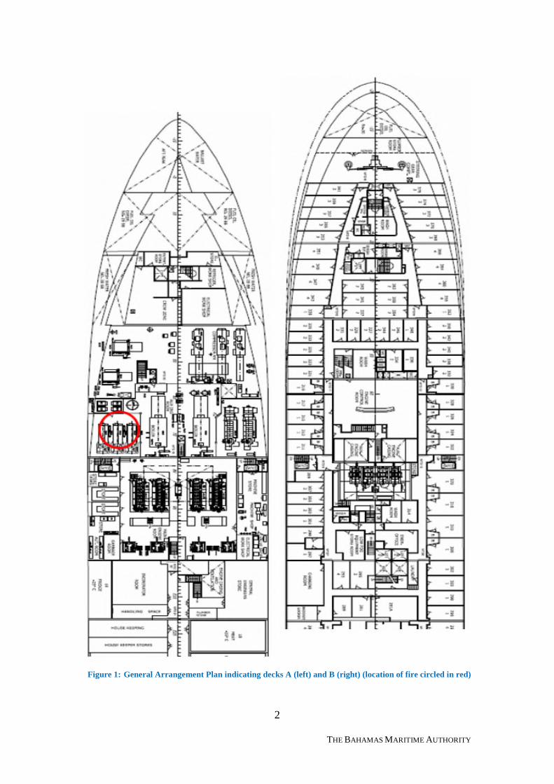
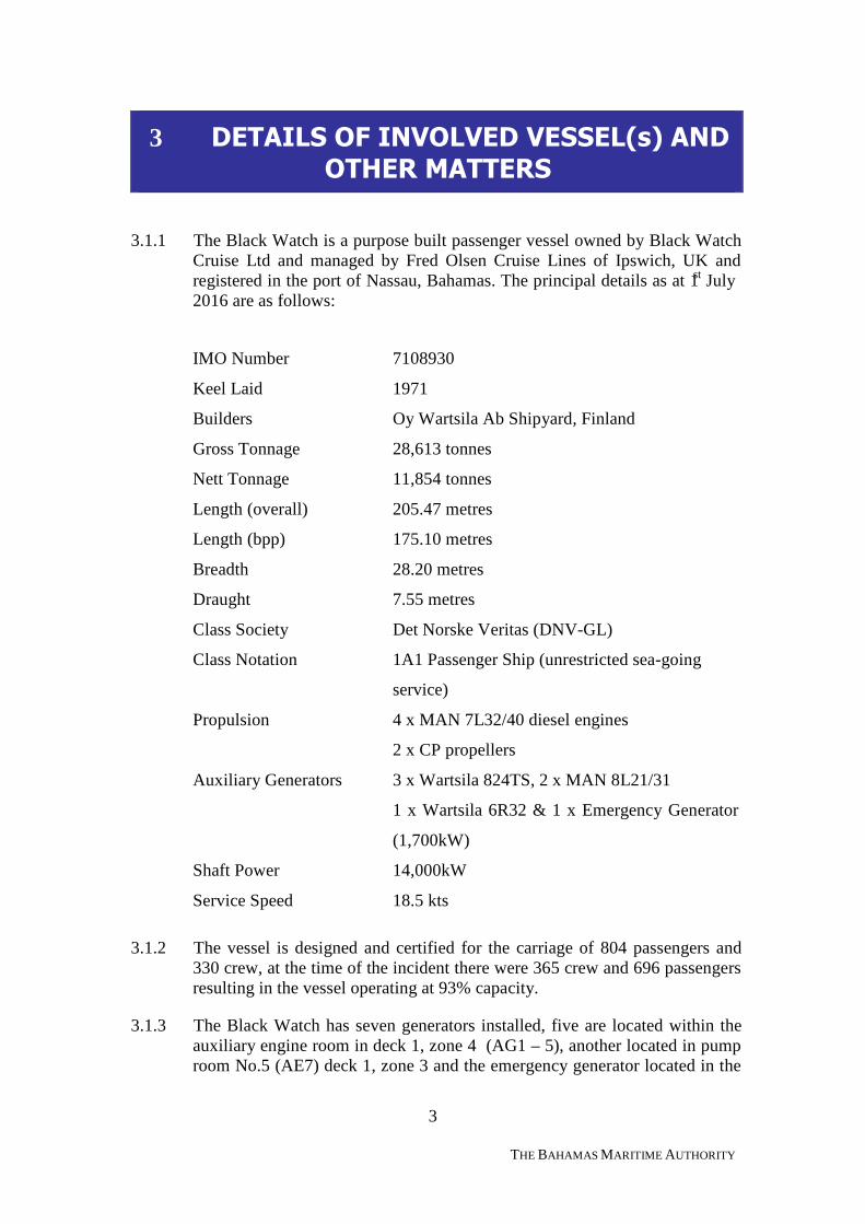
Figure 1: General Arrangement Plan indicating decks A (left) and B (right) (location of fire circled in red)
3
THE BAHAMAS MARITIME AUTHORITY
3 DETAILS OF INVOLVED VESSEL(s) ANDOTHER MATTERS
3.1.1 The Black Watch is a purpose built passenger vessel owned by Black WatchCruise Ltd and managed by Fred Olsen Cruise Lines of Ipswich, UK andregistered in the port of Nassau, Bahamas. The principal details as at 1st July2016 are as follows:
IMO Number 7108930
Keel Laid 1971
Builders Oy Wartsila Ab Shipyard, Finland
Gross Tonnage 28,613 tonnes
Nett Tonnage 11,854 tonnes
Length (overall) 205.47 metres
Length (bpp) 175.10 metres
Breadth 28.20 metres
Draught 7.55 metres
Class Society Det Norske Veritas (DNV-GL)
Class Notation 1A1 Passenger Ship (unrestricted sea-going
service)
Propulsion 4 x MAN 7L32/40 diesel engines
2 x CP propellers
Auxiliary Generators 3 x Wartsila 824TS, 2 x MAN 8L21/31
1 x Wartsila 6R32 & 1 x Emergency Generator
(1,700kW)
Shaft Power 14,000kW
Service Speed 18.5 kts
3.1.2 The vessel is designed and certified for the carriage of 804 passengers and330 crew, at the time of the incident there were 365 crew and 696 passengersresulting in the vessel operating at 93% capacity.
3.1.3 The Black Watch has seven generators installed, five are located within theauxiliary engine room in deck 1, zone 4 (AG1 – 5), another located in pumproom No.5 (AE7) deck 1, zone 3 and the emergency generator located in the
4
THE BAHAMAS MARITIME AUTHORITY
emergency generator room on deck 9 zone 4. AE6 was removed in 2005during a vessel refit and never replaced.
3.2 Vessel Certification
3.2.1 At the time of the incident the vessel was classed with DNV-GL and allstatutory certificates remained valid.
Primary Certificates:
Certificate of Class issued 16 Nov 2015 expiry 30 Nov 2016International Tonnage Certificate issued 15 Jun 2005 expiry -International Load Line Certificate issued 13 Jan 2013 expiry 30 Nov 2016Passenger Ship Safety Certificate issued 16 Nov 2015 expiry 31 Aug 2016Safety Management Certificate issued 10 Apr 2012 expiry 21 Apr 2017Document of Compliance issued 07 Nov 2014 expiry 19 Oct 2019Maritime Labour Certificate issued 05 Aug 2013 expiry 09 Jul 2018Safe Manning Document issued 01 Jul 2013 expiry 30 Jun 2018
3.3 Port State and Flag State Inspections
3.3.1 The vessel was inspected by Norwegian Maritime Authority Port StateControl (Paris-MoU) on the 15th June 2016 in Alesund, Norway with nodeficiencies recorded.
3.3.2 The Bahamas Annual Safety Inspection (ASI) was carried out on the 28th
December 2015 in Las Palmas, Gran Canaries with no deficiencies recorded.
3.4 Duty Watchkeepers
3.4.1 The following watch team members were on watch in their respectivelocations between the hours of 0800 to 1200.
The Master (36 years of age) of the vessel held an unlimited Master MarinerCertificate at the management level (II/2)1 required by the Standards ofTraining, Certification and Watchkeeping (STCW) issued by Finland on 02nd
October 2012 and endorsed by the Commonwealth of the Bahamas on 13th
June 2016, and was duly recognized in accordance with the provisions ofRegulation I/10 of the STCW 1978 convention. At the time of the incident hewas approaching the end of this contract having been on board for 2 months.The Master has been the Captain since May 2015 operating a two month on,two month off rotation. Prior to May 2015 he was the Chief Officer on boarda sister vessel the m.v Boudicca.
1 Specification of minimum standard of competence for Masters and Chief Mates on ships of 500 grosstonnage or more.
5
THE BAHAMAS MARITIME AUTHORITY
The Chief Officer (39 years of age) of the vessel held an unlimited MasterMariner Certificate at the management level (II/2) required by STCW issuedby Finland on 22nd July 2010 and endorsed by the Commonwealth of theBahamas on 30th September 2013 and duly recognized in accordance withthe provisions of regulation I/10 of the STCW 1978 convention. The ChiefOfficer arrived on board at the same time as the Master in May 2016 for thestart of his 6th contract period.
The Chief Engineer (51 years of age) held STCW III/22 Chief EngineeringOfficer qualification at the management level since 26th September 2014,endorsed by the Commonwealth of the Bahamas and duly recognized inaccordance with the provisions of regulation I/10 of the STCW 1978convention. He joined the vessel 5 days prior to the incident having beenassigned to Black Watch since June 2015. He has been with Fred OlsenCruise Line for 15 years serving on board all three sister vessels as ChiefEngineer since 2008.
Bridge Watchkeepers
Senior Third Officer (OOW) – Joined Fred Olsen Cruise Lines as a deckcadet in 2009 and sailed on sister vessels Boudicca and Balmoral. Promotedto Officer in Charge of Navigation Watch upon obtaining his Certificate ofCompetency STCW II/1 in 2013, issued by the Maritime and CoastguardAgency (MCA) and started this contract 2.5 weeks prior to the incidenthaving spent one year onboard.
Engineering Watchkeepers
The on-coming 3rd Engineer took over the engineering watch at 0800 havingrelieved the second 3rd Engineer with nothing significant to report. TheEngineer Officer of the Watch (EOOW) joined the vessel at the end of Mayfor his first contract with Fred Olsen Cruise Lines. He gained an Officer inCharge of an Engineering Watch Certificate (STCW III/1) in April 2015issued by Norway.
3.5 Fatigue
3.5.1 The Fidelio Time and Attendance system used on board confirmed that priorto the emergency all crew were in compliance with the statutory hours of restrequirements3. At the point of the emergency the Master advised that theMLC compliance was suspended until the vessel was able to resume normaloperations.
3.6 Substance Abuse
2 Specification of minimum standard of competence for the Chief Engineer Officers and SecondEngineer Officers on ships powered by main propulsion machinery of 3,000kW propulsion power ormore.3 Required by the International Convention of Standards of Training, Certification and Watchkeepingfor Seafarers. 1978 as amended (STCW) and the Maritime Labour Convention, 2006 (MLC 2006)
6
THE BAHAMAS MARITIME AUTHORITY
3.6.1 Although no alcohol testing was carried out following the incident, there wasno evidence to suggest that substance abuse was a contributory factor.
3.7 Emergency Organisation – Code Bravo
3.7.1 Code Bravo is a code name used to indicate a fire on board. In the event ofan engine room fire the engineer on duty and the motorman on duty aredespatched to investigate the nature of the incident. Once the Code Bravo isconfirmed, the following teams are mustered as per the EmergencyProcedures Manual and assembled at their designated locations:
1 Central Command Team Location: bridge2 On Scene Command Team Location: scene of incident3 Area Control Team Location: scene of incident4 Rapid response Team Location: scene of incident5 Fire Teams Location: various
3.8 Low Fog System
3.8.1 The fixed application system fitted on board is a Flexi-Fog FireExtinguishing System manufactured by Heien-Larssen and fitted on board inDecember 1999. The system was inspected by service agents Autronica Fireand Security AS on the 15th June 2016. The manual spray system provides anetwork of nozzles throughout the auxiliary engine room. The nozzle housesa deflector plate causing water to spray out over a large area. The water issupplied initially from a tank pressurised by compressed nitrogen, once thetank pressure falls, as a nozzle issues water, a salt water pump cuts inautomatically to maintain the water supply as long as is necessary.
3.9 Related Incident
3.9.1 On the 25th January 2015 the m.v Boudicca, a sister vessel within the FredOlsen fleet suffered a similar auxiliary engine room fire while enroute to thePort of Arrecife, Lanzarote (Canary Islands). The exact location of the firewas found to be at the forward, starboard side, of the auxiliary engine No.1.Upon further investigation it was determined that the fire was initiated byfuel leaking from a broken fuel oil pressure gauge supply line, igniting oncontact with a hot surface in the vicinity of the turbo charger, resulting insignificant damage to auxiliary engines No.1, 2 and 3 and the surroundingspace including cabling, deck head, fixtures and fittings.
***
7
THE BAHAMAS MARITIME AUTHORITY
4 NARRATIVE OF EVENTS
4.1 All times noted in this report are given in the style of the standard 24-hourclock without additional annotations. The vessel time used on board at thetime of the incident was Universal Coordinated Time (UTC) +1.
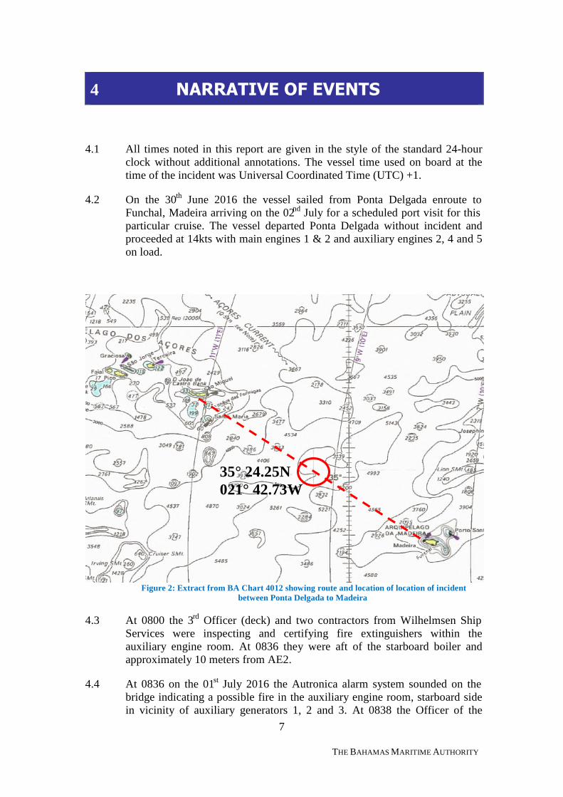
4.2 On the 30th June 2016 the vessel sailed from Ponta Delgada enroute toFunchal, Madeira arriving on the 02nd July for a scheduled port visit for thisparticular cruise. The vessel departed Ponta Delgada without incident andproceeded at 14kts with main engines 1 & 2 and auxiliary engines 2, 4 and 5on load.
Figure 2: Extract from BA Chart 4012 showing route and location of location of incidentbetween Ponta Delgada to Madeira
4.3 At 0800 the 3rd Officer (deck) and two contractors from Wilhelmsen ShipServices were inspecting and certifying fire extinguishers within theauxiliary engine room. At 0836 they were aft of the starboard boiler andapproximately 10 meters from AE2.
4.4 At 0836 on the 01st July 2016 the Autronica alarm system sounded on thebridge indicating a possible fire in the auxiliary engine room, starboard sidein vicinity of auxiliary generators 1, 2 and 3. At 0838 the Officer of the
35° 24.25N021° 42.73W
8
THE BAHAMAS MARITIME AUTHORITY
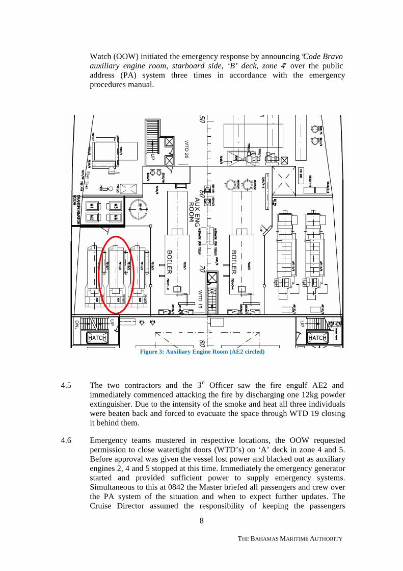
Watch (OOW) initiated the emergency response by announcing “Code Bravoauxiliary engine room, starboard side, ‘B’ deck, zone 4” over the publicaddress (PA) system three times in accordance with the emergencyprocedures manual.
Figure 3: Auxiliary Engine Room (AE2 circled)
4.5 The two contractors and the 3rd Officer saw the fire engulf AE2 andimmediately commenced attacking the fire by discharging one 12kg powderextinguisher. Due to the intensity of the smoke and heat all three individualswere beaten back and forced to evacuate the space through WTD 19 closingit behind them.
4.6 Emergency teams mustered in respective locations, the OOW requestedpermission to close watertight doors (WTD’s) on ‘A’ deck in zone 4 and 5.Before approval was given the vessel lost power and blacked out as auxiliaryengines 2, 4 and 5 stopped at this time. Immediately the emergency generatorstarted and provided sufficient power to supply emergency systems.Simultaneous to this at 0842 the Master briefed all passengers and crew overthe PA system of the situation and when to expect further updates. TheCruise Director assumed the responsibility of keeping the passengers
9
THE BAHAMAS MARITIME AUTHORITY
informed of the situation and did so every 5 minutes until 0940 followed by10-minute intervals thereafter.
4.7 One minute later the Master called the Superintendent of Black Watch on thesatellite phone providing a brief summary of the situation onboard. TheSuperintendent initiated emergency procedures ashore in order to providemaximum technical and operational support to the vessel, passengers andcrew. Ipswich, UK and Oslo, Norway offices stood up emergency supportteams.
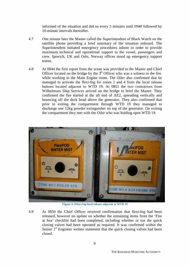
4.8 At 0844 the first report from the scene was provided to the Master and ChiefOfficer located on the bridge by the 3rd Officer who was a witness to the firewhile working in the Main Engine room. The Oiler also confirmed that hemanaged to activate the flexi-fog for zones 1 and 4 from the local releasebuttons located adjacent to WTD 19. At 0851 the two contractors fromWilhelmsen Ship Services arrived on the bridge to brief the Master. Theyconfirmed the fire started at the aft end of AE2, spreading vertically andbouncing off the deck head above the generator. They also confirmed thatprior to exiting the compartment through WTD 19 they managed todischarge one 12kg powder extinguisher on top of the generator. On exitingthe compartment they met with the Oiler who was holding open WTD 19.
Figure 4: Flexi-Fog local release adjacent to WTD 19
4.9 At 0850 the Chief Officer received confirmation that flexi-fog had beenreleased, however no update on whether the remaining items from the ‘Fireat Sea’ checklist had been completed, including whether or not the quickclosing valves had been operated as required. It was confirmed within theSenior 1st Engineer written statement that the quick closing valves had beenclosed.
10
THE BAHAMAS MARITIME AUTHORITY
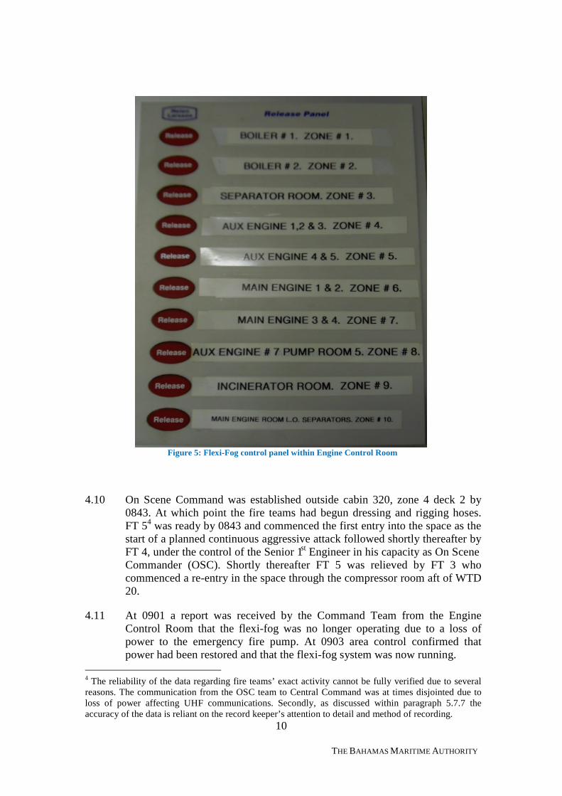
Figure 5: Flexi-Fog control panel within Engine Control Room
4.10 On Scene Command was established outside cabin 320, zone 4 deck 2 by0843. At which point the fire teams had begun dressing and rigging hoses.FT 54 was ready by 0843 and commenced the first entry into the space as thestart of a planned continuous aggressive attack followed shortly thereafter byFT 4, under the control of the Senior 1st Engineer in his capacity as On SceneCommander (OSC). Shortly thereafter FT 5 was relieved by FT 3 whocommenced a re-entry in the space through the compressor room aft of WTD20.
4.11 At 0901 a report was received by the Command Team from the EngineControl Room that the flexi-fog was no longer operating due to a loss ofpower to the emergency fire pump. At 0903 area control confirmed thatpower had been restored and that the flexi-fog system was now running.
4 The reliability of the data regarding fire teams’ exact activity cannot be fully verified due to severalreasons. The communication from the OSC team to Central Command was at times disjointed due toloss of power affecting UHF communications. Secondly, as discussed within paragraph 5.7.7 theaccuracy of the data is reliant on the record keeper’s attention to detail and method of recording.
11
THE BAHAMAS MARITIME AUTHORITY
4.12 Over the course of the next five minutes, the vessel lost propulsion due to aloss of cooling capability to the main engines. In addition, the EngineControl Room was evacuated due to the presence of dense, black smoke thatwas filling the compartment from below making it unattainable to anyone notwearing breathing apparatus.
4.13 At 0911 WTD 19 was opened to allow access to the auxiliary engine roomby the fire teams. At this point all WTD’s to the auxiliary engine room wereopen. In addition, WTD 10 separating the Engine Control Room from thestaging area and On Scene Command Team was reset on the bridge in orderto operate manually.
4.14 The On Scene Command reported to all stations that the fire in the auxiliaryengine room was under control. The Safety Officer also reported that therewas a lot of smoke confined to decks 1 and 2 within fire zone 4.
4.15 At 0926 all crew were accounted for, one member of the crew was stuck inthe forward elevator located in fire zone 1 but was evacuated from theelevator at 1104 with no injuries.
4.16 Due to the firefighting effort a port list started to develop which promptedthe Command Team to consider restricting the use of flexi-fog and fire hosesto avoid potentially increasing the vessel’s list.
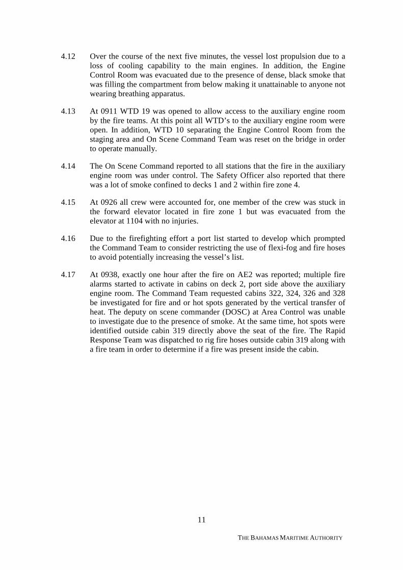
4.17 At 0938, exactly one hour after the fire on AE2 was reported; multiple firealarms started to activate in cabins on deck 2, port side above the auxiliaryengine room. The Command Team requested cabins 322, 324, 326 and 328be investigated for fire and or hot spots generated by the vertical transfer ofheat. The deputy on scene commander (DOSC) at Area Control was unableto investigate due to the presence of smoke. At the same time, hot spots wereidentified outside cabin 319 directly above the seat of the fire. The RapidResponse Team was dispatched to rig fire hoses outside cabin 319 along witha fire team in order to determine if a fire was present inside the cabin.
12
THE BAHAMAS MARITIME AUTHORITY
Figure 6: Cabins 322, 324, 326 and 328 investigated for damage
4.18 The emergency generator stopped working at 0938 resulting in the loss ofemergency lighting, communications and electrical power required forpowering essential firefighting system integral to support the firefightingeffort.
4.19 All previous reports of smoke were confined to decks 1 and 2 within firezone 4. At 0941 evidence of smoke migration was confirmed by theactivation of a fire alarm on deck 3, zone 4 (crew staircase).
4.20 At 0944 Ultra High Frequency (UHF) internal communications failed, thecommand team maintained communication with the five dedicatedemergency locations using runners delivering verbal and written messages toand from each location. At 0950 UHF communications were restoredhowever over the course of the following 9 hours UHF communicationsoperated intermittently and resulted in the use of runners continually. Thepublic address system remained in operation and passengers continued to bebriefed on the developing situation.
4.21 The Master at this point consulted with Fred Olsen Marine ServicesTechnical Support (FOMS) who in turn liaised directly with DNV-GLEmergency Response Service (ERS)5 regarding the vessel’s stability basedon draught and vessel loading at the point of departure to determine whateffect the firefighting effort may have on the stability of the vessel.
5 Service provided by DNV-GL; in the event of an emergency DNV Emergency Response Serviceprovides technical expertise to assist the vessel with a particular emergency.
13
THE BAHAMAS MARITIME AUTHORITY
4.22 At 0955 the Chief Engineer briefed the Master on the progress of the fire-fighting effort and a situational report on vital systems. The Chief Engineerconfirmed that there was no power available due to inoperable emergencygenerator and therefore as a consequence no fire main pressure. The ChiefEngineer recommended to the Master that the priority should be to restoreelectrical power and utilize fire extinguishers to fight the fire.
4.23 Two minutes later a fire was confirmed on top of AE3, FT 4 used fireextinguishers to fight the fire. Within minutes FT 4 retreated from the spaceback to the staging area once all available fire extinguishers in the spacewere depleted.
4.24 At 1006 ventilation was confirmed stopped and acknowledged on the bridge.At this time the bridge also received an update from the Safety Officerstating smoke had migrated within the staircase up to deck 5 in zone 4, whichwas confirmed by the activation of smoke alarms in the vicinity.
4.25 Power was temporarily restored throughout the vessel as the emergencygenerator started at 1010. At 1019, the emergency generator shutdown andthe Chief Electrician continued to investigate the fault.
4.26 Smoke continued to migrate vertically within zone 4 crew staircase C; at1027 the smoke was reported on deck 7 however at 1029 the hotel managerinformed the Command Team that “no smoke or heat, everything okay inguest areas”, the source of this report is not known and may well be amisinterpretation of the fact that smoke was present within crew staircase Con deck 7. At this point the DOSC discussed with the Master and the ChiefOfficer whether to release CO2 into the auxiliary engine room. The DOSCbriefed the Master on the available firefighting equipment and confirmed thatthe firefighting teams had a low number of BA bottles and extinguishers leftonboard. The option was taken not to release CO2 but instead attempt torestore power by fixing the emergency generator.

14
THE BAHAMAS MARITIME AUTHORITY
Figure 7: Smoke dispersing onto deck 10 starboard side at 1029
4.27 The Chief Engineer determined that the fault with the emergency generatorwas overheating; to improve ventilation he smashed one of the windowsopposite the generator exhaust on deck 9 to increase the volume of cooler airto the generator intake.
4.28 At 1059, with intermittent power, fire main pressure and no breathingapparatus, the Chief Officer and Master discussed the use of CO2 as the firehad not been extinguished.
4.29 At 1109 the On Scene Command reported to the Command Team that thefire in the auxiliary engine room had been extinguished however multiple hotspots remained in the vicinity. Shortly thereafter the Chief Engineerdetermined that the power demanded from the emergency generator was toogreat and therefore the focus should be to attempt to restart AG7 instead.
4.30 The Master discussed with the Chief Officer his concern regarding thevessel’s stability. The result of this discussion prompted the Master tocontact FOMS a further time in order to assist the Master in prioritising theemergency effort onboard.
4.31 At 1147 the Safety Officer contacted the Command Team to inform themthat the fire in the auxiliary engine room had reignited, the deck in adjacentcabins on deck 2 had buckled and deformed through exposure to heat and hotspots were identified in cabins on deck 3 above.
4.32 At 1154 the Chief Engineer called the bridge and confirmed that the EngineControl Room was now manned.
4.33 Over the course of the next 20 minutes boundary cooling continued usingportable fire extinguishers in cabins on 2 deck within fire zone 4. It wasreported from the ECR to the Command Team that the temperature reading
15
THE BAHAMAS MARITIME AUTHORITY
of 170°C continued to rise in the auxiliary engine room. The On SceneCommander provided the Command Team with a situation report stating:“port side boiler okay, starboard boiler no good, generator 1, 2 and 3 gone,everything contained and fire teams standing by with fire extinguishers,flooring gone”.
4.34 The Command Team instructed the DOSC that the emergency generatorwould be started for 5 minutes and “we need to do whatever we can with thistime”. From 1233 the emergency fire pump was started and fire mainpressure restored, activating the sprinklers in cabins 311 to 317 until 1246thirteen minutes later. The Master at this point contacted MRCC PontaDelgada located in the Azores to request assistance.
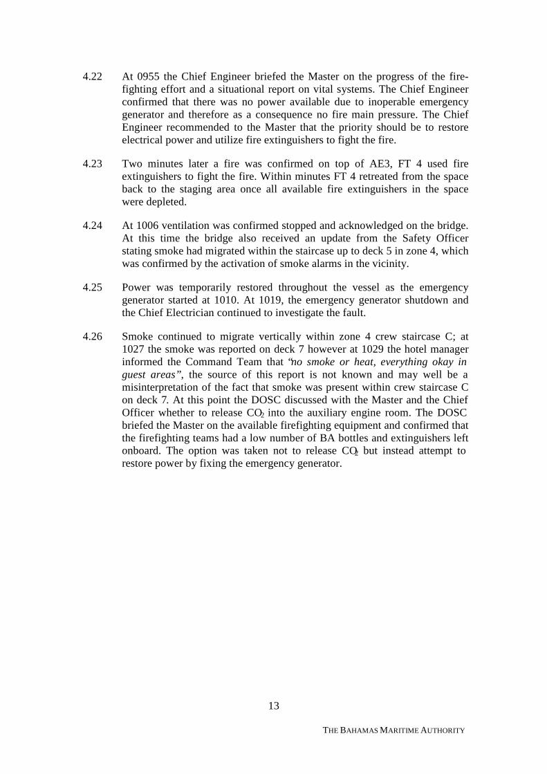
4.35 At 1331 a distress signal was sent from the Black Watch to all shipsrequesting maritime assistance in position 35° 24.25N 021° 42.73W. At 1338the m.v Ocean Caesar, a Panamanian registered bulk carrier, responded with“how is your situation” from position 35° 33.50N 021° 15.50Wapproximately 26nm to the North of the Black Watch. The Black Watchresponded with “still fighting the fire, we need you to stay close”.The OceanCaesar replied, “We are proceeding to the location but we cannot come closeas we are chartering coals”. The Ocean Caesar remained in close proximityuntil approximately 1730 at which point it was released by MRCC andcontinued on passage.
Figure 8: Distress message transmitted at 1331 (UTC+1)
4.36 By 1406 the AG7 was up and running providing sufficient power to operateemergency equipment, however due to the significant damage sustained tothe auxiliary engine room, multiple systems were damaged beyondtemporary repair.
4.37 Transfer of water in the bilge into holding tanks commenced at 1447. Shortlythereafter the Safety Officer reported to the Command Team that thetemperature had reduced to 50°C in the auxiliary engine room and theremoval of water was being achieved slowly.
16
THE BAHAMAS MARITIME AUTHORITY
4.38 At 1541 the Safety Officer was in contact with MRCC Delgada who reportedthat helicopters were 6 to 8 hours away, one tugboat enroute from Tenerifeand the other from Ponta Delgada with an estimated time of arrival on themorning of 02nd July. A decision was then made by the Master that thehelicopters were not required as the situation was under control and systemswere being restored.
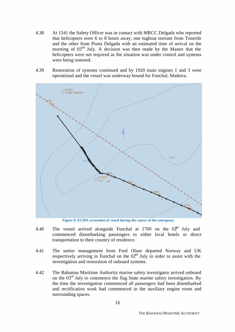
4.39 Restoration of systems continued and by 1920 main engines 1 and 3 wereoperational and the vessel was underway bound for Funchal, Madeira.
Figure 9: ECDIS screenshot of vessel during the course of the emergency
4.40 The vessel arrived alongside Funchal at 1700 on the 02nd July andcommenced disembarking passengers to either local hotels or directtransportation to their country of residence.
4.41 The senior management from Fred Olsen departed Norway and UKrespectively arriving in Funchal on the 02nd July in order to assist with theinvestigation and restoration of onboard systems.
4.42 The Bahamas Maritime Authority marine safety investigator arrived onboardon the 03rd July to commence the flag State marine safety investigation. Bythe time the investigation commenced all passengers had been disembarkedand rectification work had commenced in the auxiliary engine room andsurrounding spaces.
17
THE BAHAMAS MARITIME AUTHORITY
4.43 The vessel sailed from Funchal on the 08th July bound ultimately for Dovervia Ferrol, Spain where permanent repairs took place prior to commencingthe next cruise due to commence on the 17th July from Tilbury, UK. TheInspections and Surveys department of the Bahamas Maritime Authority inconsultation with DNV-GL approved a single voyage without passengersfrom Funchal, Madeira to a port in Europe where repairs could take placeprior to arrival in the UK. The vessel was issued with a Short TermPassenger Ship Safety Certificate (PSSC) by DNV-GL prior to arrival inDover however the material condition of the vessel could not be verifiedprior to arriving in the UK, as the vessel was not attended by DNV-GL sincedeparting Funchal, Madeira and prior to its arrival in the UK.
***
18
THE BAHAMAS MARITIME AUTHORITY
5 ANALYSIS AND DISCUSSION
5.1 Aim
5.1.1 The purpose of the analysis is to determine the contributory causes andcircumstances of the accident as a basis for making recommendations toprevent similar accidents occurring in the future.
5.2 Location of the fire
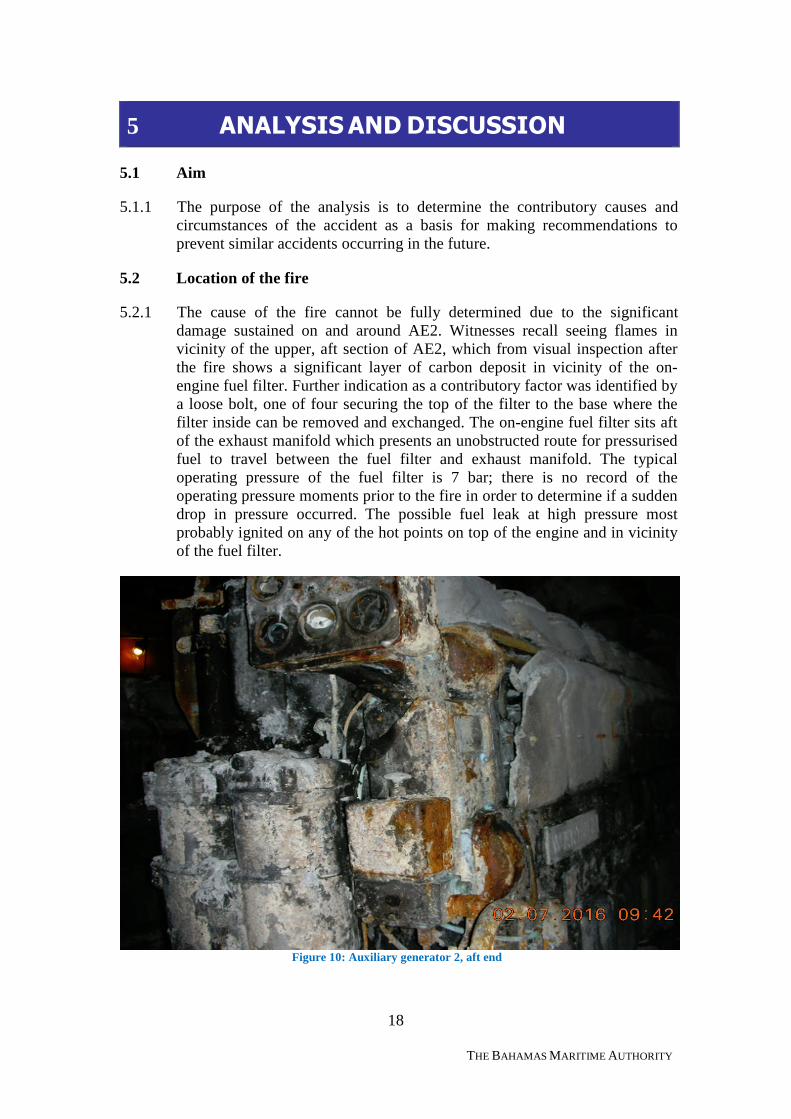
5.2.1 The cause of the fire cannot be fully determined due to the significantdamage sustained on and around AE2. Witnesses recall seeing flames invicinity of the upper, aft section of AE2, which from visual inspection afterthe fire shows a significant layer of carbon deposit in vicinity of the on-engine fuel filter. Further indication as a contributory factor was identified bya loose bolt, one of four securing the top of the filter to the base where thefilter inside can be removed and exchanged. The on-engine fuel filter sits aftof the exhaust manifold which presents an unobstructed route for pressurisedfuel to travel between the fuel filter and exhaust manifold. The typicaloperating pressure of the fuel filter is 7 bar; there is no record of theoperating pressure moments prior to the fire in order to determine if a suddendrop in pressure occurred. The possible fuel leak at high pressure mostprobably ignited on any of the hot points on top of the engine and in vicinityof the fuel filter.
Figure 10: Auxiliary generator 2, aft end
19
THE BAHAMAS MARITIME AUTHORITY
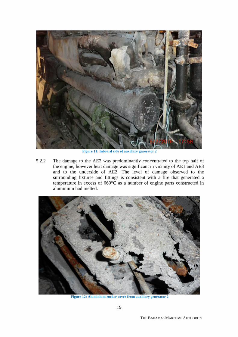
Figure 11: Inboard side of auxiliary generator 2
5.2.2 The damage to the AE2 was predominantly concentrated to the top half ofthe engine; however heat damage was significant in vicinity of AE1 and AE3and to the underside of AE2. The level of damage observed to thesurrounding fixtures and fittings is consistent with a fire that generated atemperature in excess of 660°C as a number of engine parts constructed inaluminium had melted.
Figure 12: Aluminium rocker cover from auxiliary generator 2
20
THE BAHAMAS MARITIME AUTHORITY
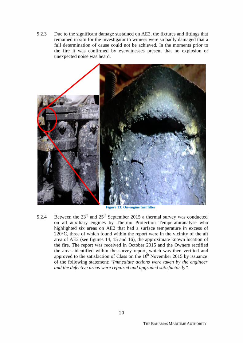
5.2.3 Due to the significant damage sustained on AE2, the fixtures and fittings thatremained in situ for the investigator to witness were so badly damaged that afull determination of cause could not be achieved. In the moments prior tothe fire it was confirmed by eyewitnesses present that no explosion orunexpected noise was heard.
Figure 13: On-engine fuel filter
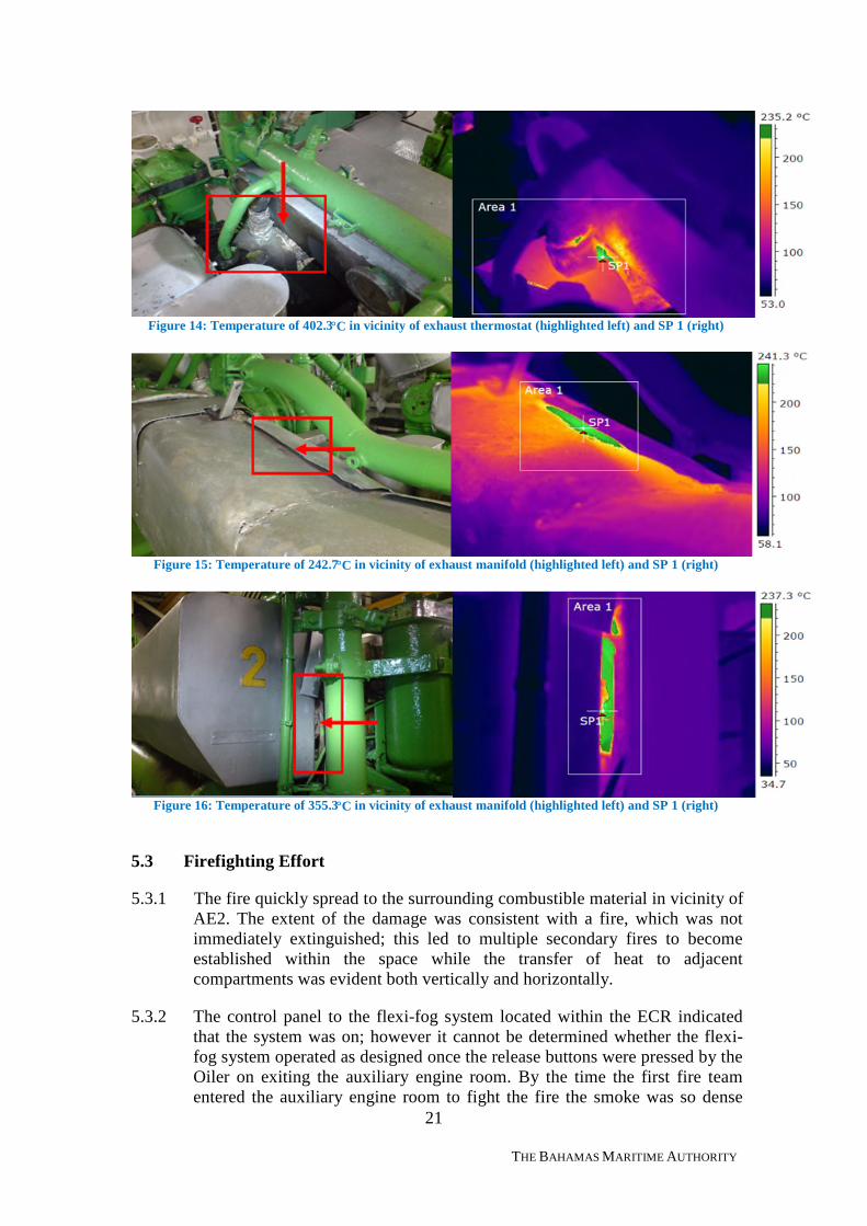
5.2.4 Between the 23rd and 25th September 2015 a thermal survey was conductedon all auxiliary engines by Thermo Protection Temperaturanalyse whohighlighted six areas on AE2 that had a surface temperature in excess of220°C, three of which found within the report were in the vicinity of the aftarea of AE2 (see figures 14, 15 and 16), the approximate known location ofthe fire. The report was received in October 2015 and the Owners rectifiedthe areas identified within the survey report, which was then verified andapproved to the satisfaction of Class on the 16th November 2015 by issuanceof the following statement: “Immediate actions were taken by the engineerand the defective areas were repaired and upgraded satisfactorily”.
21
THE BAHAMAS MARITIME AUTHORITY
Figure 14: Temperature of 402.3°C in vicinity of exhaust thermostat (highlighted left) and SP 1 (right)
Figure 15: Temperature of 242.7°C in vicinity of exhaust manifold (highlighted left) and SP 1 (right)
Figure 16: Temperature of 355.3°C in vicinity of exhaust manifold (highlighted left) and SP 1 (right)
5.3 Firefighting Effort
5.3.1 The fire quickly spread to the surrounding combustible material in vicinity ofAE2. The extent of the damage was consistent with a fire, which was notimmediately extinguished; this led to multiple secondary fires to becomeestablished within the space while the transfer of heat to adjacentcompartments was evident both vertically and horizontally.
5.3.2 The control panel to the flexi-fog system located within the ECR indicatedthat the system was on; however it cannot be determined whether the flexi-fog system operated as designed once the release buttons were pressed by theOiler on exiting the auxiliary engine room. By the time the first fire teamentered the auxiliary engine room to fight the fire the smoke was so dense
22
THE BAHAMAS MARITIME AUTHORITY
they were unable to confirm whether flexi-fog was operating. What is knownis that shortly before the fire team entered the space the fire pump lost powerand was unable to supply water to the flexi-fog system. This was reset in theECR prior to evacuating and the message was relayed to the bridge that flexi-fog was operating although no physical confirmation of the system operatingcould be achieved.
5.3.3 The fixed firefighting system onboard was inspected on the 11th June 2016by Autronica Fire and Security AS. A certificate was issued to the Owners onthe 15th June 2016 certifying that the water mist system and equipment wasinspected and that the certificate was valid for a period of one year. Prior tothe issuance of the certificate a number of deficiencies were required to berectified, particular areas of concern were identified as follows:
a. “Tested all the local protection areas in the engine spaces. Started toblow compressed air through the sections however it was not possible tocomplete this test due to the type of nozzles (Flexi-Fog type 30) whichrequires higher pressure to open completely (maximum compressed aironboard is 6 bar). Therefore it was only possible to make a visual ofinspection of the nozzles and check their position.”
Blowing compressed air through the nozzle can result in debris beingdeposited in vicinity of the mesh strainer located within the nozzle,potentially restricting the moving parts and possibly reducing or stoppingwater flow affecting the overall efficiency of the nozzle. MSC.1/Circ.14326
recommends ‘blow dry compressed air or nitrogen through the dischargepiping of dry pipe systems, or otherwise confirm the pipework and nozzlesare clear of any obstructions. This may require the removal of nozzles, ifapplicable.’
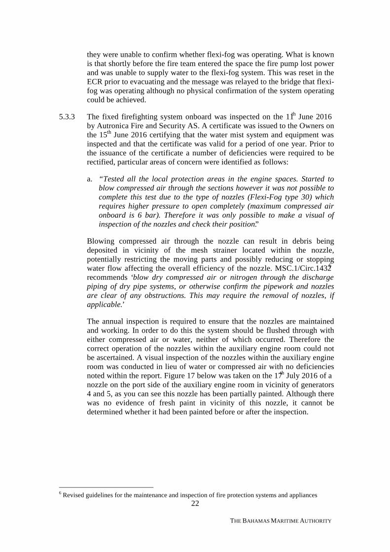
The annual inspection is required to ensure that the nozzles are maintainedand working. In order to do this the system should be flushed through witheither compressed air or water, neither of which occurred. Therefore thecorrect operation of the nozzles within the auxiliary engine room could notbe ascertained. A visual inspection of the nozzles within the auxiliary engineroom was conducted in lieu of water or compressed air with no deficienciesnoted within the report. Figure 17 below was taken on the 17th July 2016 of anozzle on the port side of the auxiliary engine room in vicinity of generators4 and 5, as you can see this nozzle has been partially painted. Although therewas no evidence of fresh paint in vicinity of this nozzle, it cannot bedetermined whether it had been painted before or after the inspection.
6 Revised guidelines for the maintenance and inspection of fire protection systems and appliances
23
THE BAHAMAS MARITIME AUTHORITY
Figure 17: Damaged nozzle located in vicinity of auxiliary generators 4 and 5
b. “Checked the batteries inside the main panel cabinet in ECR. Those arecompletely dead. There are no spares available onboard, the electricianalready ordered new batteries. Those must be replaced as soon aspossible in order to guarantee the functionality of the system.”
MSC.1/Circ.1432 lists the weekly testing and inspections to be carried out,one of which is to verify all fire detection and fire alarm control panelindicators are functional. It could be possible for the batteries to fail withinthe weekly testing and inspection schedule. It could also be an indication thatthe weekly testing and inspection schedule was not being conducted inaccordance with MSC.1/Circ.1432.
c. “The inside of the main panel cabinet in ECR is incredibly dirty…it isstrongly recommended to find a solution.”
Observations ‘b’ and ‘c’ above provide the investigators with an indicationthat the material condition of the fire alarm control panel was not beingmaintained satisfactorily.
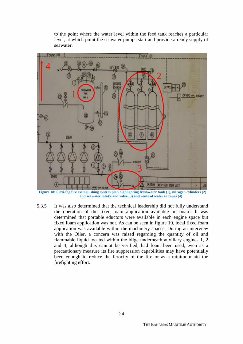
5.3.4 The supply and operation of the flexi-fog system was not fully understood bysenior technical leadership on board. The system is a dry pipe, low-pressuresystem, which uses freshwater, stored within a feeder tank, pressurized bynitrogen in order to deliver water through the respective nozzles. It wasdetermined through the course of an interview that one senior Officer wasunder the impression that it was a freshwater system and once the freshwateris depleted, the system stops operating. The flexi-fog system is freshwater up
24
THE BAHAMAS MARITIME AUTHORITY
to the point where the water level within the feed tank reaches a particularlevel, at which point the seawater pumps start and provide a ready supply ofseawater.
Figure 18: Flexi-fog fire extinguishing system plan highlighting freshwater tank (1), nitrogen cylinders (2)and seawater intake and valve (3) and route of water to zones (4)
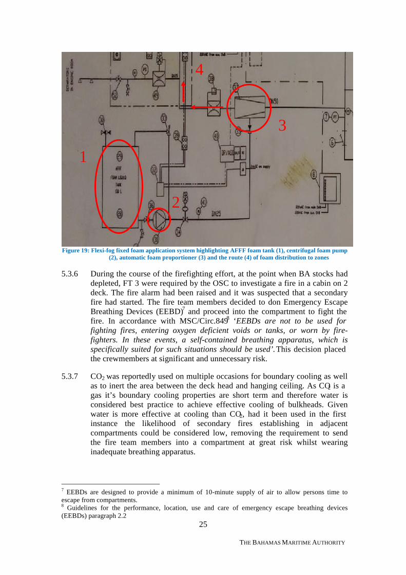
5.3.5 It was also determined that the technical leadership did not fully understandthe operation of the fixed foam application available on board. It wasdetermined that portable eductors were available in each engine space butfixed foam application was not. As can be seen in figure 19, local fixed foamapplication was available within the machinery spaces. During an interviewwith the Oiler, a concern was raised regarding the quantity of oil andflammable liquid located within the bilge underneath auxiliary engines 1, 2and 3, although this cannot be verified, had foam been used, even as aprecautionary measure its fire suppression capabilities may have potentiallybeen enough to reduce the ferocity of the fire or as a minimum aid thefirefighting effort.
1
2
3
4
25
THE BAHAMAS MARITIME AUTHORITY
Figure 19: Flexi-fog fixed foam application system highlighting AFFF foam tank (1), centrifugal foam pump(2), automatic foam proportioner (3) and the route (4) of foam distribution to zones
5.3.6 During the course of the firefighting effort, at the point when BA stocks haddepleted, FT 3 were required by the OSC to investigate a fire in a cabin on 2deck. The fire alarm had been raised and it was suspected that a secondaryfire had started. The fire team members decided to don Emergency EscapeBreathing Devices (EEBD)7 and proceed into the compartment to fight thefire. In accordance with MSC/Circ.8498 ‘EEBDs are not to be used forfighting fires, entering oxygen deficient voids or tanks, or worn by fire-fighters. In these events, a self-contained breathing apparatus, which isspecifically suited for such situations should be used’.This decision placedthe crewmembers at significant and unnecessary risk.
5.3.7 CO2 was reportedly used on multiple occasions for boundary cooling as wellas to inert the area between the deck head and hanging ceiling. As CO2 is agas it’s boundary cooling properties are short term and therefore water isconsidered best practice to achieve effective cooling of bulkheads. Givenwater is more effective at cooling than CO2, had it been used in the firstinstance the likelihood of secondary fires establishing in adjacentcompartments could be considered low, removing the requirement to sendthe fire team members into a compartment at great risk whilst wearinginadequate breathing apparatus.
7 EEBDs are designed to provide a minimum of 10-minute supply of air to allow persons time toescape from compartments.8 Guidelines for the performance, location, use and care of emergency escape breathing devices(EEBDs) paragraph 2.2
1
4
2
3
26
THE BAHAMAS MARITIME AUTHORITY
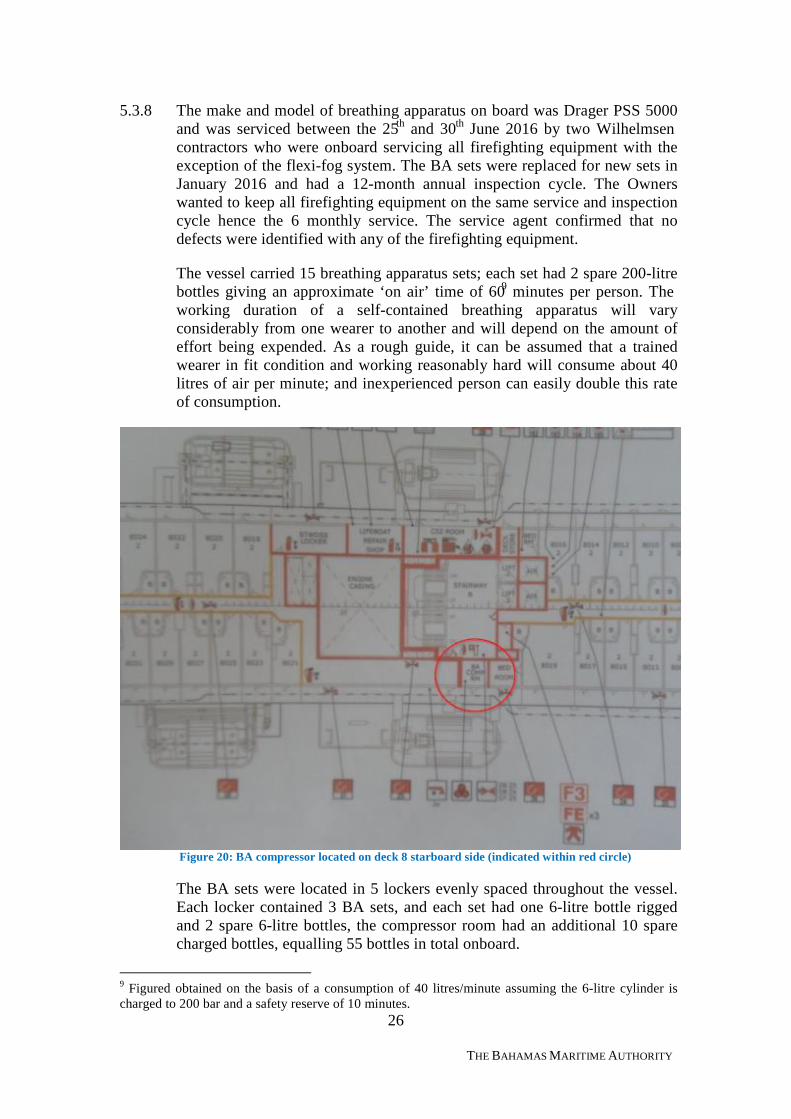
5.3.8 The make and model of breathing apparatus on board was Drager PSS 5000and was serviced between the 25th and 30th June 2016 by two Wilhelmsencontractors who were onboard servicing all firefighting equipment with theexception of the flexi-fog system. The BA sets were replaced for new sets inJanuary 2016 and had a 12-month annual inspection cycle. The Ownerswanted to keep all firefighting equipment on the same service and inspectioncycle hence the 6 monthly service. The service agent confirmed that nodefects were identified with any of the firefighting equipment.
The vessel carried 15 breathing apparatus sets; each set had 2 spare 200-litrebottles giving an approximate ‘on air’ time of 609 minutes per person. Theworking duration of a self-contained breathing apparatus will varyconsiderably from one wearer to another and will depend on the amount ofeffort being expended. As a rough guide, it can be assumed that a trainedwearer in fit condition and working reasonably hard will consume about 40litres of air per minute; and inexperienced person can easily double this rateof consumption.
Figure 20: BA compressor located on deck 8 starboard side (indicated within red circle)
The BA sets were located in 5 lockers evenly spaced throughout the vessel.Each locker contained 3 BA sets, and each set had one 6-litre bottle riggedand 2 spare 6-litre bottles, the compressor room had an additional 10 sparecharged bottles, equalling 55 bottles in total onboard.
9 Figured obtained on the basis of a consumption of 40 litres/minute assuming the 6-litre cylinder ischarged to 200 bar and a safety reserve of 10 minutes.
27
THE BAHAMAS MARITIME AUTHORITY
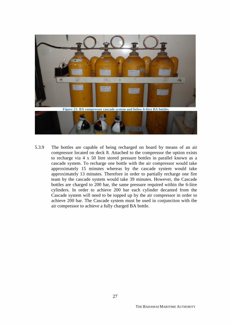
Figure 21: BA compressor cascade system and below 6-litre BA bottles
5.3.9 The bottles are capable of being recharged on board by means of an aircompressor located on deck 8. Attached to the compressor the option existsto recharge via 4 x 50 litre stored pressure bottles in parallel known as acascade system. To recharge one bottle with the air compressor would takeapproximately 15 minutes whereas by the cascade system would takeapproximately 13 minutes. Therefore in order to partially recharge one fireteam by the cascade system would take 39 minutes. However, the Cascadebottles are charged to 200 bar, the same pressure required within the 6-litrecylinders. In order to achieve 200 bar each cylinder decanted from theCascade system will need to be topped up by the air compressor in order toachieve 200 bar. The Cascade system must be used in conjunction with theair compressor to achieve a fully charged BA bottle.
28
THE BAHAMAS MARITIME AUTHORITY
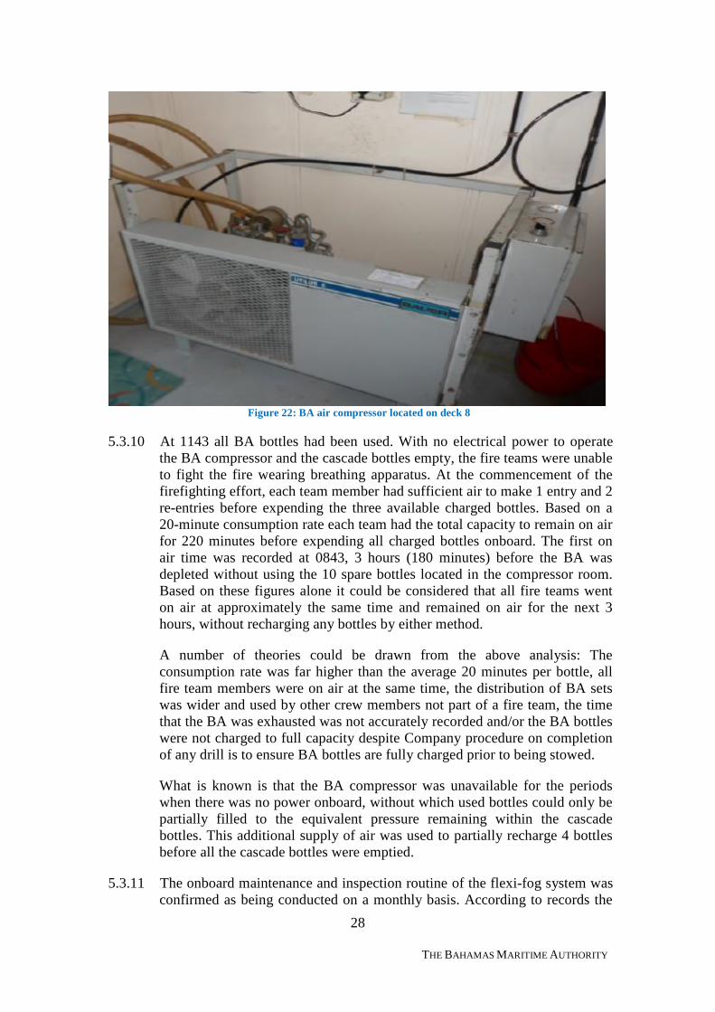
Figure 22: BA air compressor located on deck 8
5.3.10 At 1143 all BA bottles had been used. With no electrical power to operatethe BA compressor and the cascade bottles empty, the fire teams were unableto fight the fire wearing breathing apparatus. At the commencement of thefirefighting effort, each team member had sufficient air to make 1 entry and 2re-entries before expending the three available charged bottles. Based on a20-minute consumption rate each team had the total capacity to remain on airfor 220 minutes before expending all charged bottles onboard. The first onair time was recorded at 0843, 3 hours (180 minutes) before the BA wasdepleted without using the 10 spare bottles located in the compressor room.Based on these figures alone it could be considered that all fire teams wenton air at approximately the same time and remained on air for the next 3hours, without recharging any bottles by either method.
A number of theories could be drawn from the above analysis: Theconsumption rate was far higher than the average 20 minutes per bottle, allfire team members were on air at the same time, the distribution of BA setswas wider and used by other crew members not part of a fire team, the timethat the BA was exhausted was not accurately recorded and/or the BA bottleswere not charged to full capacity despite Company procedure on completionof any drill is to ensure BA bottles are fully charged prior to being stowed.
What is known is that the BA compressor was unavailable for the periodswhen there was no power onboard, without which used bottles could only bepartially filled to the equivalent pressure remaining within the cascadebottles. This additional supply of air was used to partially recharge 4 bottlesbefore all the cascade bottles were emptied.
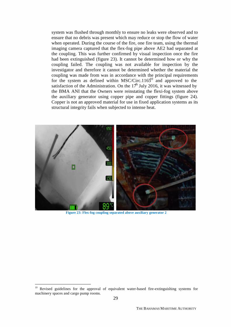
5.3.11 The onboard maintenance and inspection routine of the flexi-fog system wasconfirmed as being conducted on a monthly basis. According to records the
29
THE BAHAMAS MARITIME AUTHORITY
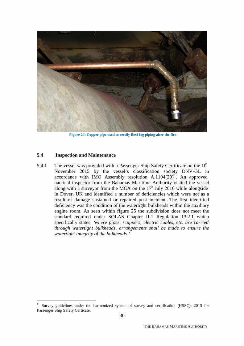
system was flushed through monthly to ensure no leaks were observed and toensure that no debris was present which may reduce or stop the flow of waterwhen operated. During the course of the fire, one fire team, using the thermalimaging camera captured that the flex-fog pipe above AE2 had separated atthe coupling. This was further confirmed by visual inspection once the firehad been extinguished (figure 23). It cannot be determined how or why thecoupling failed. The coupling was not available for inspection by theinvestigator and therefore it cannot be determined whether the material thecoupling was made from was in accordance with the principal requirementsfor the system as defined within MSC/Circ.116510 and approved to thesatisfaction of the Administration. On the 17th July 2016, it was witnessed bythe BMA ANI that the Owners were reinstating the flexi-fog system abovethe auxiliary generator using copper pipe and copper fittings (figure 24).Copper is not an approved material for use in fixed application systems as itsstructural integrity fails when subjected to intense heat.
Figure 23: Flex-fog coupling separated above auxiliary generator 2
10 Revised guidelines for the approval of equivalent water-based fire-extinguishing systems formachinery spaces and cargo pump rooms.
30
THE BAHAMAS MARITIME AUTHORITY
Figure 24: Copper pipe used to rectify flexi-fog piping after the fire
5.4 Inspection and Maintenance
5.4.1 The vessel was provided with a Passenger Ship Safety Certificate on the 10th
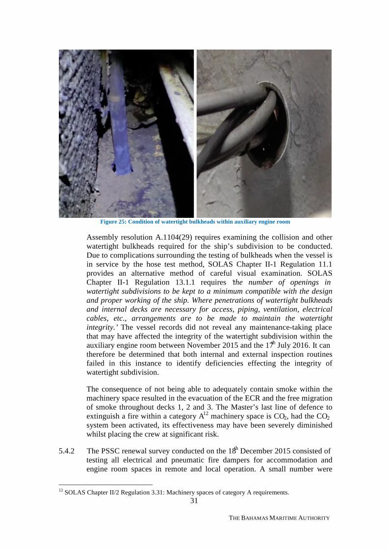
November 2015 by the vessel’s classification society DNV-GL inaccordance with IMO Assembly resolution A.1104(29)11. An approvednautical inspector from the Bahamas Maritime Authority visited the vesselalong with a surveyor from the MCA on the 17th July 2016 while alongsidein Dover, UK and identified a number of deficiencies which were not as aresult of damage sustained or repaired post incident. The first identifieddeficiency was the condition of the watertight bulkheads within the auxiliaryengine room. As seen within figure 25 the subdivision does not meet thestandard required under SOLAS Chapter II-1 Regulation 13.2.1 whichspecifically states: ‘where pipes, scuppers, electric cables, etc. are carriedthrough watertight bulkheads, arrangements shall be made to ensure thewatertight integrity of the bulkheads.’
11 Survey guidelines under the harmonized system of survey and certification (HSSC), 2015 forPassenger Ship Safety Certicate.
31
THE BAHAMAS MARITIME AUTHORITY
Figure 25: Condition of watertight bulkheads within auxiliary engine room
Assembly resolution A.1104(29) requires examining the collision and otherwatertight bulkheads required for the ship’s subdivision to be conducted.Due to complications surrounding the testing of bulkheads when the vessel isin service by the hose test method, SOLAS Chapter II-1 Regulation 11.1provides an alternative method of careful visual examination. SOLASChapter II-1 Regulation 13.1.1 requires ‘the number of openings inwatertight subdivisions to be kept to a minimum compatible with the designand proper working of the ship. Where penetrations of watertight bulkheadsand internal decks are necessary for access, piping, ventilation, electricalcables, etc., arrangements are to be made to maintain the watertightintegrity.’ The vessel records did not reveal any maintenance-taking placethat may have affected the integrity of the watertight subdivision within theauxiliary engine room between November 2015 and the 17th July 2016. It cantherefore be determined that both internal and external inspection routinesfailed in this instance to identify deficiencies effecting the integrity ofwatertight subdivision.
The consequence of not being able to adequately contain smoke within themachinery space resulted in the evacuation of the ECR and the free migrationof smoke throughout decks 1, 2 and 3. The Master’s last line of defence toextinguish a fire within a category A12 machinery space is CO2, had the CO2
system been activated, its effectiveness may have been severely diminishedwhilst placing the crew at significant risk.
5.4.2 The PSSC renewal survey conducted on the 18th December 2015 consisted oftesting all electrical and pneumatic fire dampers for accommodation andengine room spaces in remote and local operation. A small number were
12 SOLAS Chapter II/2 Regulation 3.31: Machinery spaces of category A requirements.
32
THE BAHAMAS MARITIME AUTHORITY
found with deficiencies resulting in the issuance of a condition of Class(CC). The deficiencies concerned external fire dampers and air intakes,which were found in a corroded, holed or wasted condition. The sevenidentified deficiencies were rectified and the CC was later deleted with thefollowing statement: “effective repairs carried out satisfactorily”.
The Owners are ultimately responsible for the condition and operation of firedampers. Regular on board inspections should be conducted to ensure the firedampers structural integrity is not compromised by verifying their conditionand operation to ensure in the event of a fire the engine space can becontained.
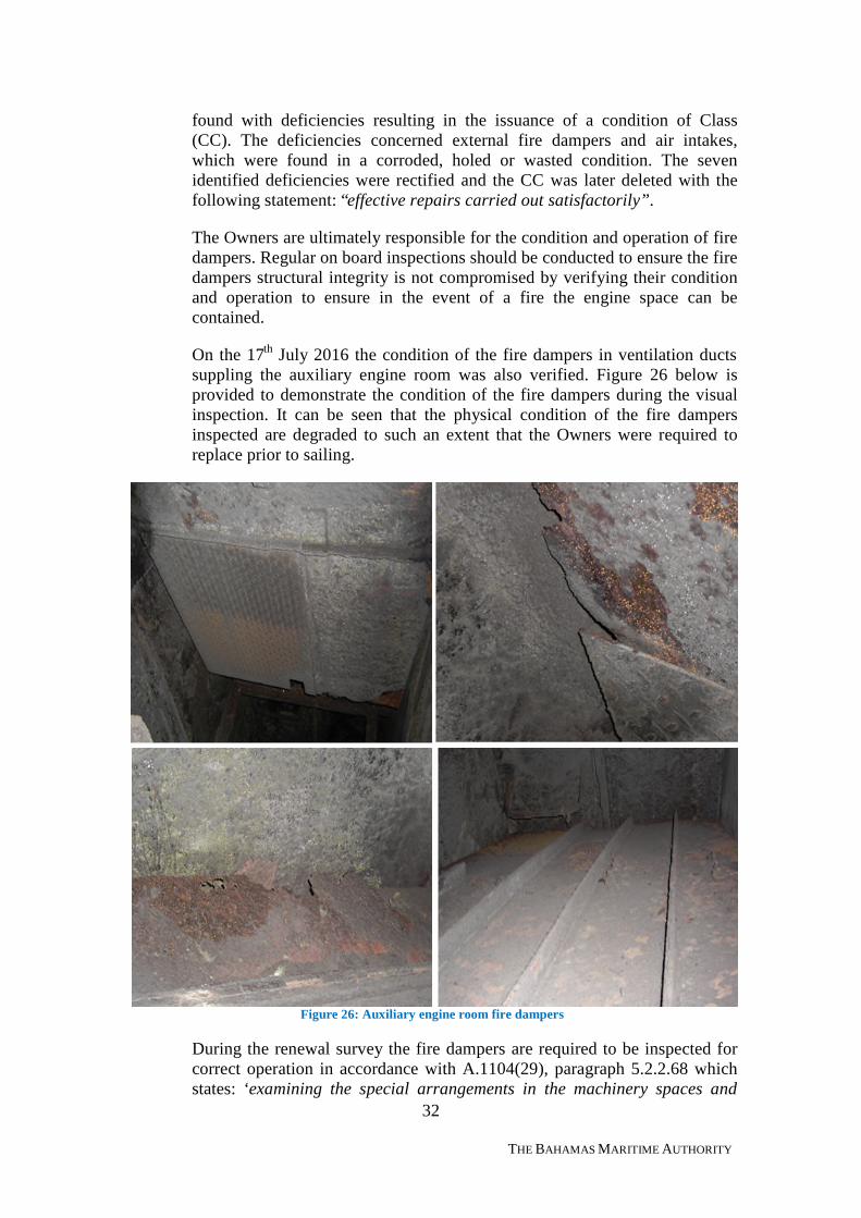
On the 17th July 2016 the condition of the fire dampers in ventilation ductssuppling the auxiliary engine room was also verified. Figure 26 below isprovided to demonstrate the condition of the fire dampers during the visualinspection. It can be seen that the physical condition of the fire dampersinspected are degraded to such an extent that the Owners were required toreplace prior to sailing.
Figure 26: Auxiliary engine room fire dampers
During the renewal survey the fire dampers are required to be inspected forcorrect operation in accordance with A.1104(29), paragraph 5.2.2.68 whichstates: ‘examining the special arrangements in the machinery spaces and
33
THE BAHAMAS MARITIME AUTHORITY
confirming, as far as practicable and as appropriate, the operation of theremote means of control provided for the opening and closing of theskylights, the release of smoke, the closure of the funnel and ventilationopenings…’ and under the Class survey requirements the survey ‘shall coverexamination of fire doors and fire dampers in ventilation ducts’.
In addition to the requirements and standards set by Class, assemblyresolution A.1052(27)13 stipulates when fire dampers cannot comply with theSOLAS convention due to absence, non-compliance or substantialdeterioration the condition may warrant the consideration of Port StateControl to detain the vessel. The Norwegian Maritime Authority Port StateControl (Paris-MoU) conducted an inspection on the 15th June 2016 inAlesund, Norway and did not identify any deficiency with the fire damperslocated in or associated with auxiliary engine room ventilation.
In addition to the PSSC renewal survey, the vessel also underwent an annualflag State inspection by an Approved Nautical Inspector (ANI) on the 28th
December 2015. In accordance with the Bahamas Inspection Checklist theANI is to ‘check the condition of, and if applicable, verify the following areoperational – Watertight doors, port holes, ventilator closures, fire flaps,other closing devices, sounding pipes and air/vent pipes’. No deficiencieswere identified by the ANI in regard to the above systems. However the ANIis not conducting a survey but instead an inspection on the general conditionof the vessel utilizing the checklist as an aide memoir. This one-day ‘snapshot’ of the vessel does not allow for a more detailed inspection of all safetyrelated appliances and fixtures.
It can be determined with a certain degree of certainty that the degradedcondition of the fire dampers shown in figure 26 was not a result of firedamage from the auxiliary engine room fire on the 1st July 2016. Further itcan also be determined with a degree of certainty that the condition of firedampers did not deteriorate to such an extent that the Owners or PSCinspections would not have had sufficient opportunity to potentially identifytheir condition.
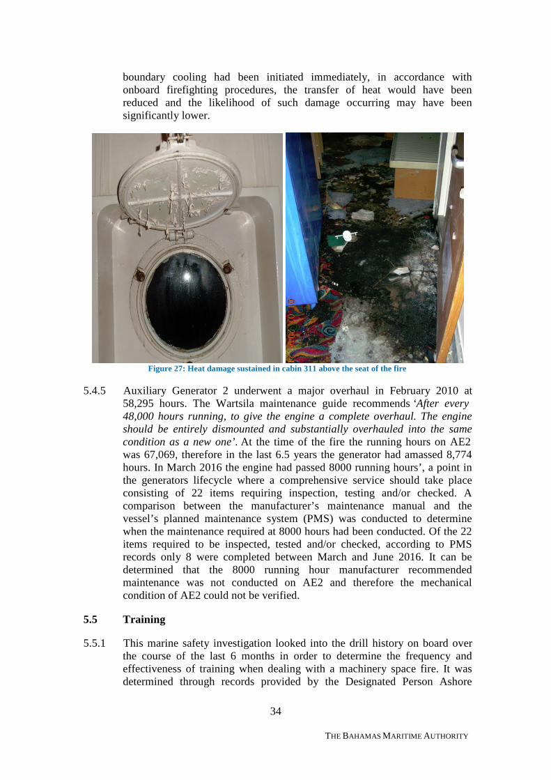
5.4.3 The ‘A’ class insulation on the deck head of the auxiliary engine roomprovided adequate structural fire protection sufficient to contain the heatfrom transferring for approximately 60 minutes. As the fire continued to burnin excess of one hour the fire protection insulation degraded allowing thetransfer of heat to adjacent compartments, this resulted in secondary fires toestablish themselves in the crew cabins located above the seat of the fire.Damage sustained to these compartments can be seen within figure 27 below.
5.4.4 Due to the loss of power and emergency fire pumps no fixed applicationsystem operated within cabins affected by the transfer of heat. Boundarycooling was initiated but not until 0940, by which time the extreme heatgenerated by the fire had transferred through the bulkheads affecting theintegrity and habitability of adjacent compartments (see figure 27). If
13 Procedures for Port State Control, Appendix 2 – Guidelines for the detention of ships
34
THE BAHAMAS MARITIME AUTHORITY
boundary cooling had been initiated immediately, in accordance withonboard firefighting procedures, the transfer of heat would have beenreduced and the likelihood of such damage occurring may have beensignificantly lower.
Figure 27: Heat damage sustained in cabin 311 above the seat of the fire
5.4.5 Auxiliary Generator 2 underwent a major overhaul in February 2010 at58,295 hours. The Wartsila maintenance guide recommends ‘After every48,000 hours running, to give the engine a complete overhaul. The engineshould be entirely dismounted and substantially overhauled into the samecondition as a new one’. At the time of the fire the running hours on AE2was 67,069, therefore in the last 6.5 years the generator had amassed 8,774hours. In March 2016 the engine had passed 8000 running hours’, a point inthe generators lifecycle where a comprehensive service should take placeconsisting of 22 items requiring inspection, testing and/or checked. Acomparison between the manufacturer’s maintenance manual and thevessel’s planned maintenance system (PMS) was conducted to determinewhen the maintenance required at 8000 hours had been conducted. Of the 22items required to be inspected, tested and/or checked, according to PMSrecords only 8 were completed between March and June 2016. It can bedetermined that the 8000 running hour manufacturer recommendedmaintenance was not conducted on AE2 and therefore the mechanicalcondition of AE2 could not be verified.
5.5 Training
5.5.1 This marine safety investigation looked into the drill history on board overthe course of the last 6 months in order to determine the frequency andeffectiveness of training when dealing with a machinery space fire. It wasdetermined through records provided by the Designated Person Ashore
35
THE BAHAMAS MARITIME AUTHORITY
(DPA) that the crew had not conducted a Code Bravo drill in either theauxiliary engine room or the main engine room in this period.
5.5.2 One drill had been conducted in May within Pump Room 5, zone 3, withinwhich auxiliary AG7 is located. The drill was coordinated by the SafetyOfficer, the same Safety Officer who was on board for the fire on AE2 on the01st July. The drill scenario and reporting form (SAF 02.1k) aims to test andactivate all safety and equipment functions with the exception of theemergency generator. The objectives of the drill were to test the effectivenessof the hose, foam and inline eductor preparation, hose handling and entry tocompartment using proper firefighting techniques. Medical team to exercisecasualty handling and a full CO2 muster was to be achieved. All starboardside lifeboats to be prepared to the embarkation deck and sent away withtheir operating crews. The drill report also provides a section for drillevaluation. In summary, the evaluation report stated the following:“improper search procedure when searching for casualties and that thestarboard lifeboat team were disorganized and required further training.”
5.5.3 When comparing the actual fire and the drill conducted there are two distinctdifferences. The emergency generator was not routinely operated duringdrills, it was tested weekly for no more than one hour at a time but it wasrarely used on-load for a period greater than one hour. Secondly, the boatswere not prepared to the embarkation deck on the 01st July in the event theMaster decided to abandon ship.
5.5.4 The senior positions on board rotate with their opposite numbersapproximately every 2-3 months. The senior Officers present at the time ofthe drill conducted in May within pump room number 5 were the same seniorOfficers present during the fire on the 01st July, with the exception of theChief Engineer. Therefore, despite this being the only machinery based CodeBravo drill in the previous six months; the senior Officers on board on the01st July could be considered the most current.
5.5.5 Despite not conducting a drill within either auxiliary or main machineryspaces, a drill was conducted within pump room 5, which could beconsidered a mechanical space given the location of AG7. Form SAF 02.1kreport form is not detailed enough to determine the overall effectiveness ofthe drill in accordance with emergency response procedures. Key emergencyresponse procedures are not included on the form, which is used not only toprovide instruction and guidance on the objectives to be achieved but also tocritique the drill in order to identify areas for the crew to improve on.
5.6 System Redundancy
5.6.1 Within four minutes of the Code Bravo announcement engines 2, 4 and 5 hadbeen shut down. At this point the emergency generator started immediatelyand restored power to essential equipment in order to fight the fire. Theemergency generator ran without fault for 56 minutes until the ChiefElectrician shut it down locally due to failure of the voltage stabilisation unit.A decision which should have been made by the Master given Central
36
THE BAHAMAS MARITIME AUTHORITY
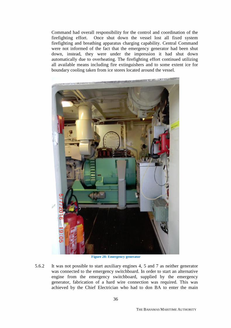
Command had overall responsibility for the control and coordination of thefirefighting effort. Once shut down the vessel lost all fixed systemfirefighting and breathing apparatus charging capability. Central Commandwere not informed of the fact that the emergency generator had been shutdown, instead, they were under the impression it had shut downautomatically due to overheating. The firefighting effort continued utilizingall available means including fire extinguishers and to some extent ice forboundary cooling taken from ice stores located around the vessel.
Figure 28: Emergency generator
5.6.2 It was not possible to start auxiliary engines 4, 5 and 7 as neither generatorwas connected to the emergency switchboard. In order to start an alternativeengine from the emergency switchboard, supplied by the emergencygenerator, fabrication of a hard wire connection was required. This wasachieved by the Chief Electrician who had to don BA to enter the main
37
THE BAHAMAS MARITIME AUTHORITY
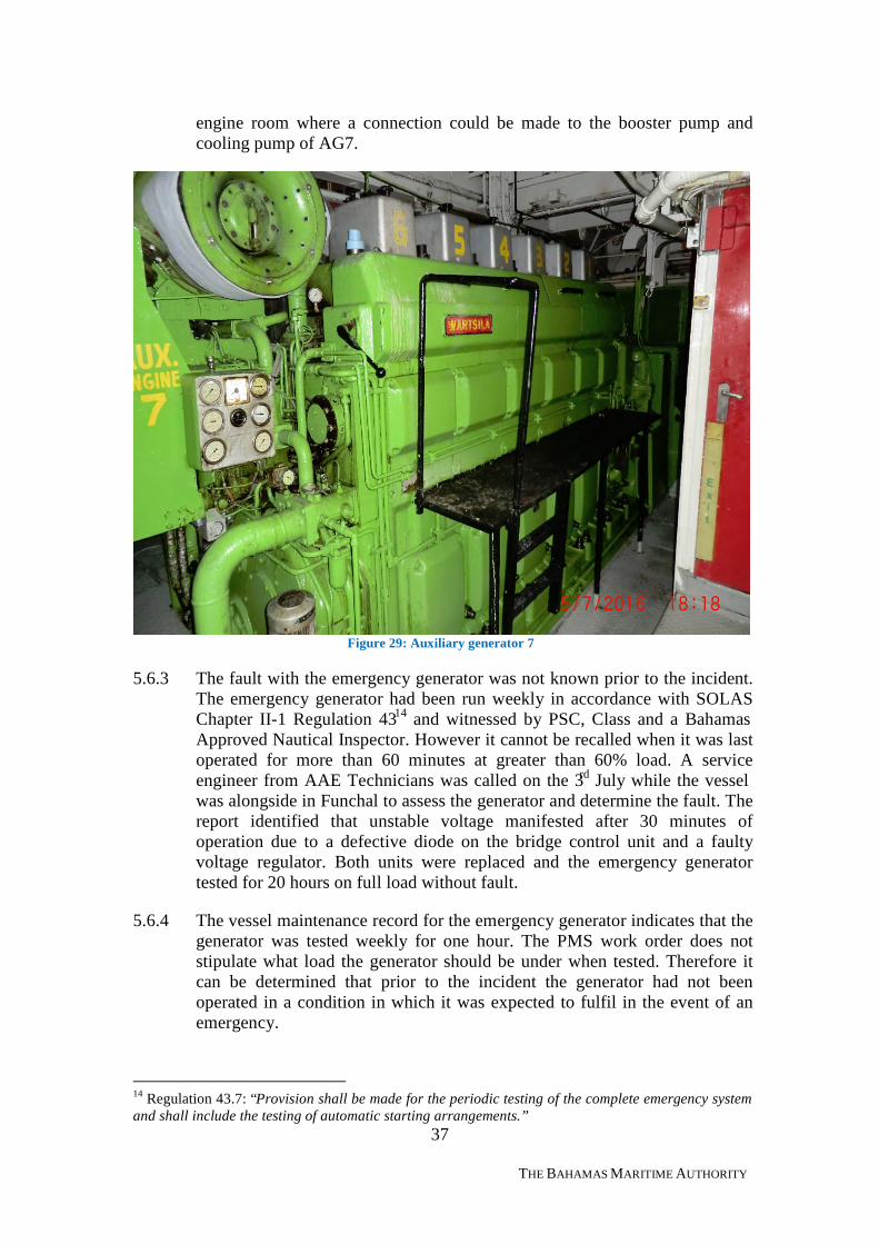
engine room where a connection could be made to the booster pump andcooling pump of AG7.
Figure 29: Auxiliary generator 7
5.6.3 The fault with the emergency generator was not known prior to the incident.The emergency generator had been run weekly in accordance with SOLASChapter II-1 Regulation 4314 and witnessed by PSC, Class and a BahamasApproved Nautical Inspector. However it cannot be recalled when it was lastoperated for more than 60 minutes at greater than 60% load. A serviceengineer from AAE Technicians was called on the 3rd July while the vesselwas alongside in Funchal to assess the generator and determine the fault. Thereport identified that unstable voltage manifested after 30 minutes ofoperation due to a defective diode on the bridge control unit and a faultyvoltage regulator. Both units were replaced and the emergency generatortested for 20 hours on full load without fault.
5.6.4 The vessel maintenance record for the emergency generator indicates that thegenerator was tested weekly for one hour. The PMS work order does notstipulate what load the generator should be under when tested. Therefore itcan be determined that prior to the incident the generator had not beenoperated in a condition in which it was expected to fulfil in the event of anemergency.
14 Regulation 43.7: “Provision shall be made for the periodic testing of the complete emergency systemand shall include the testing of automatic starting arrangements.”
38
THE BAHAMAS MARITIME AUTHORITY
5.7 Emergency Procedures
5.7.1 The overall coordination and communication effort on board moments priorto the Code Bravo up until the fire had been confirmed as extinguishedproved disjointed. By definition the Central Command serves as the vessel’scommand, control and information centre. In order for this to be fulfilledinformation from the emergency teams located throughout the vessel shouldfeed information to the Command in order to allow overall coordination ofthe firefighting effort to be achieved. It was determined throughout thecourse of the investigation that key decisions were made without theknowledge or approval of the Command Team located on the bridge.
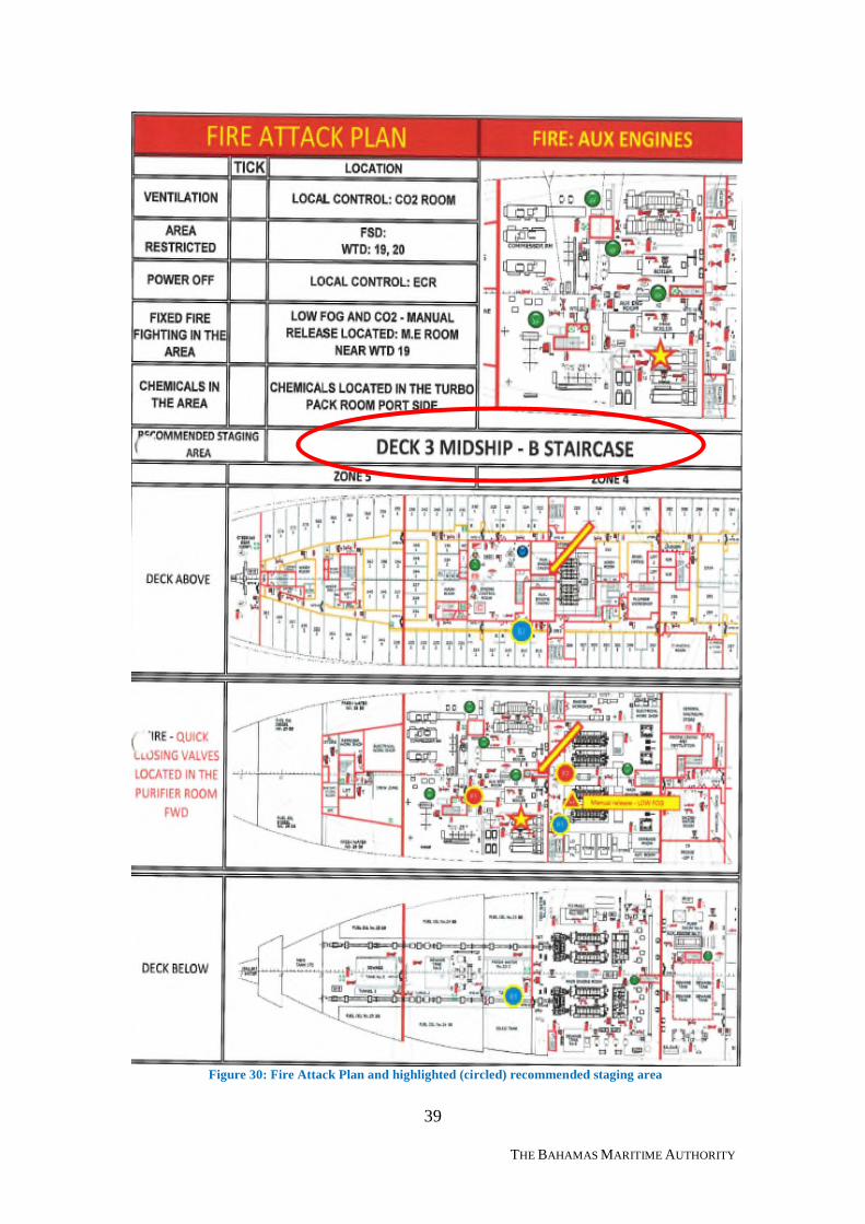
5.7.2 The establishment of the staging area outside cabin 320 was not inaccordance with the pre-planned response for a fire within the auxiliaryengine room (see figure 30, fire attack plan). Once the ECR was evacuatedand WTD 10 was allowed to remain open, there was no physical boundarybetween a smoke filled compartment and an area deemed, at the time to besuitable for controlling and coordinating fire teams entry and exit. In drillsthe crew train to incorporate a two-door separation between a smoke filledcompartment and fresh air however this is not a Company policy. This wasnot achieved in practice and instead of re-establishing the staging area to alocation further forward in fresh air, the staging area remained outside cabin320 subjecting the staging team to smoke which had migrated from the ECRthrough the open WTD 10. Further, a smoke boundary could not bemaintained due to the movement of personnel to and from the smoke filledstaging area; this allowed smoke to migrate freely.
39
THE BAHAMAS MARITIME AUTHORITY
Figure 30: Fire Attack Plan and highlighted (circled) recommended staging area
40
THE BAHAMAS MARITIME AUTHORITY
5.7.3 The Master and the Safety Officer discussed going to General EmergencyStations (GES) as it would speed up the process of abandonment should theemergency not be recoverable. On the back of this discussion the SafetyOfficer and the Master decided that if smoke migrates beyond deck 3 zone 4then the vessel would go to GES. By 1006 smoke had migrated up to deck 5within crew staircase C (zone 4) however the vessel did not go to GES. TheNavigation policy and procedures (NAV 07.01) check off sheet doesrecommend consideration is given to sounding the GES alarm.
5.7.4 There were a number of occasions when the Chief Officer was requestinginformation from various sources but not being provided with timely updatesas to the firefighting effort or equipment availability. Had the Chief Officerhad a better understanding of the damage control effort, key decisions mayhave been made from Central Command and not by individual teammembers. At one stage the emergency generator was being used to providepower to start AE7 without the knowledge of the Chief Officer who at thetime, was under the impression power was being provided to fire pumps inorder to generate sufficient water pressure to fight the fire.
5.7.5 The emergency organization manual requires the Safety Officer to report tothe ‘scene of the incident and establish communication with CentralCommand and proceed as directed’. The emergency organization manualdoes not go further in detailing the role and responsibility of the SafetyOfficer. The Safety Officer saw his role as a coordinator of the firefightingeffort having overall responsibility of the fire teams, liaising with the OSCwhilst roving throughout the vessel. The role of the On-Scene Commander isdefined within the emergency organization manual as follows: ‘direct the fireteams in attacking the fire after discussing with his/her team’.To avoid anymisunderstanding the fire teams responsibility is also defined by thefollowing statement: ‘follow orders from the On-Scene Command’.
The role of the Safety Officer is defined but unless direction is provided byCentral Command, any action taken to assist the firefighting effort is done sonot in accordance with procedure but through local routines implemented andpractised during pre-planned drills. The Safety Officer acted under his owninitiative as he had done so on all previous Code Bravo occasions. TheSafety Officer did not maintain regular communication with the CommandTeam due to the quantity of assigned roles delegated to himself. At one pointthe Safety Officer had proceeded into the compressor room aft of theauxiliary engine without BA, prior to the Fire Teams arrival whilst WTD 20was in the open position. This placed the Safety Officer in significant dangerdisplaying disregard for his own health and safety. Ultimately it could haveled to a search and rescue effort being required using up vital resources atconsiderable risk.
5.7.6 On the 01st July the Boat Deck Commander Team and Lifeboat Teammustered on the boat deck in accordance with Code Bravo procedures. TheLifeboat Team has a standing order to lower the boats to embarkation levelas soon as the Code Bravo is sounded; the team is then required to report tothe Boat Deck member that they are ready to receive passengers. This did not
41
THE BAHAMAS MARITIME AUTHORITY
happen; the lifeboats remained in the stowed and secured position on the boatdeck.
In accordance with the emergency organisation manual the Boat DeckCommander Team shall monitor the preparation and lowering of rescueboats, lifeboats and life rafts. A recent drill was conducted on the 29th May2016 and in the drill evaluation notes on SAF 02.1k form state that “all thelifeboats should be lowered to the embarkation deck once the generalemergency alarm is sounded”, this evaluation, written by the Safety Officerand witnessed by the Master was in contradiction to the emergencyprocedures required within the emergency organization manual. Theevaluation report goes on to state that “but there is a conflict with Companypolicy which is not allowing the deck commander to lower the lifeboatswithout a Senior Officer present”. The emergency organization manualmakes no reference to a Senior Officer required to be present in order tolower lifeboats, it states clearly that when a Code Bravo is sounded, ‘theLifeboat Team are to lower the boats to the embarkation level’. Theemergency procedures were not followed or adequately understood by thehigher authority on board resulting in no action being taken to rectify thismisunderstanding identified during training.
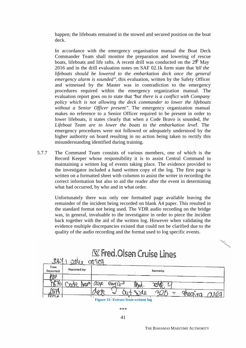
5.7.7 The Command Team consists of various members, one of which is theRecord Keeper whose responsibility it is to assist Central Command inmaintaining a written log of events taking place. The evidence provided tothe investigator included a hand written copy of the log. The first page iswritten on a formatted sheet with columns to assist the writer in recording thecorrect information but also to aid the reader after the event in determiningwhat had occurred, by who and in what order.
Unfortunately there was only one formatted page available leaving theremainder of the incident being recorded on blank A4 paper. This resulted inthe standard format not being used. The VDR audio recording on the bridgewas, in general, invaluable to the investigator in order to piece the incidentback together with the aid of the written log. However when validating theevidence multiple discrepancies existed that could not be clarified due to thequality of the audio recording and the format used to log specific events.
Figure 31: Extract from written log
***
42
THE BAHAMAS MARITIME AUTHORITY
6 CONCLUSIONS
6.1 The fire broke out at 0838 on the 01st July 2016 in vicinity of the on-enginefuel filter located at the aft end of AE2. The ignition source cannot beidentified post incident due to the significant damage sustained to AE2. Thefire continued to burn generating temperatures in excess of 660°C within theauxiliary engine room, destroying the majority of evidence and preventinginvestigators from determining actual cause.
6.2 The firefighting effort was severely hampered through a combination ofmaterial, system and human element factors, at times, resulting increwmembers acting independently to achieve a positive outcome oftendeviating from Company policy and procedures.
6.3 The lessons learned from the related incident that occurred on board the m.vBoudicca on the 25th January 2015 were clearly well understood by theCommand Team on board the Black Watch. The Command Team wereconscious of the use and duration of the flexi-fog system in order to avoid apotential list which developed on the Boudicca due to the fixed applicationhigh-fog system remaining in operation after the fire had been extinguished.
6.4 Local release buttons were activated in accordance with Companyprocedures; however a continuous supply of water through the nozzles couldnot be achieved as designed due to a loss of power, regardless of theunknown condition of the nozzles. The verification process in combinationwith the testing and inspection procedures coupled with the onboard systemknowledge is likely to have impacted the operation of the fixed applicationsystem.
6.5 A lack of adequate containment resulted in smoke and heat being able tomigrate to adjacent compartments and beyond. The degraded structuralintegrity of fire dampers enabled smoke to escape from the space enablingfresh air to enter the compartment, effectively feeding the fire. Penetrationswithin watertight bulkheads were not adequately sealed resulting in smokepassing through the subdivision into adjacent compartments, resulting in fireteams being forced on air in advance of reaching the auxiliary engine room,effectively wasting fresh air in transit. Control of WTD’s from the stagingarea to the scene of the fire was not coordinated or controlled as required inaccordance with Company procedures. The procedure for separation betweenthe affected space and staging area was not adhered to through a lack ofunderstanding of basic firefighting principles.
6.6 The option to use CO2 was discussed once primary firefighting techniqueshad been exhausted and prior to smoke reaching public areas of the ship. Itwas agreed that if smoke reaches the public areas above deck 3 then theoption to use CO2 would be reconsidered. By the time this occurred the fire
43
THE BAHAMAS MARITIME AUTHORITY
within the auxiliary engine room had been extinguished. However the firecontinued to burn within the transformer room aft of AE2 but its severity didnot warrant the use of CO2.
6.7 The continued requirement to investigate whether a fire was present withinadjacent compartments after BA stocks had been depleted resulted increwmembers being placed at risk by entering compartments whilst wearingEEBD’s without knowing the danger that existed.
6.8 Regular Code Bravo drills were conducted, recorded and evaluated by seniorOfficers on board however no drill was conducted in the auxiliary engineroom in the preceding 12 months. The auxiliary engine room is considered acompartment of significant importance, not only because of the equipmentoperated within but also because of its central location beneath the ECR. Theconsequence of the fire escalating outside the auxiliary engine room to thepoint where adjacent compartments were rendered unattainable affectedpropulsion machinery, power generation, domestic services and primarycontrol of all mechanical systems.
6.9 A minority of senior Officers demonstrated throughout the course of theincident insufficient knowledge of systems, firefighting techniques andcommand and control methods resulting in these individuals using their ownexperience to determine the best course of action, without approval orconsultation with Command. The Command team attempted to remain incontrol but without up-to-date information on equipment availability or theseverity of the fire(s) they were not in a position to best prioritise responseseffectively. This ultimately resulted in some emergency systems not beingmade available to the On Scene Commander leaving fire teams exposed atcritical times throughout the incident.
6.10 The vessel was not adequately prepared in the event the fire escalated to apoint where abandonment was deemed by Command as the last resort topreserving safety of life. The lifeboats were not lowered to the embarkationdeck allowing ready access by passengers and crew. Despite a recent drillidentifying a discrepancy in the onboard procedures, no action was taken toclarify the procedures and rectify the deficiency.
6.11 Due to the power output of auxiliary generators 1, 2 and 3 they were usedprimarily as reserve providers of power when either demand was high or anycombination of generators 4, 5 or 7 were unavailable. Although regularmaintenance was conducted on generators 1, 2 and 3, AE2 had not beenmaintained in accordance with the manufacturer’s recommended servicecycle.
***
44
THE BAHAMAS MARITIME AUTHORITY
7 RECOMMENDATIONS
Recommendations for the operator:
7.1 Consider reviewing the procedure for allocating the location of drills onboardto ensure realistic training occurs regularly within all engine rooms.
7.2 Review the requirement of periodic testing of emergency generators andconsider implementing a mechanism whereby their condition is tested toensure they are capable of operating in a condition in which they areexpected to fulfil on all Fred Olsen vessels.
7.3 Recommend refresher training for all senior Officer’s within Fred Olsen onadvance firefighting techniques.
7.4 Consider a review of the roles and responsibilities of team leaders detailedwithin the emergency organization manual.
7.5 Consider implementing a vessel system familiarisation-training package toensure all team leaders understand the limitations and capabilities ofemergency systems.
7.6 Consider increasing the level of fire protection within engine rooms on boardall Fred Olsen vessels.
***
45
THE BAHAMAS MARITIME AUTHORITY
8 ACTIONS TAKEN
8.1 Owners will arrange a meeting with Autronica to review their inspection andreporting systems and to discuss the necessity to review system/layout inview of applicable rules and regulations and make changes as deemedappropriate.
8.2 The Owners have implemented a method to use AMOS as a means tocoordinate, and record drill deficiencies.
8.3 The Owners are working on a change to the Emergency Organisation Manualto ensure it accurately reflects the routine for adequately preparing crew andguests in the event of a Code Bravo incident. A new crew alert stage orinclusion of more crew at Code Bravo is being considered, whichincorporates an additional stage between Code Bravo and GES, wherebycrew will muster and prepare for GES ahead of mustering passengers.
8.4 The Owners will continue to review planned maintenance system to allocatethe location of drills on an annual schedule.
8.5 The Owners have implemented a routine to ensure emergency generators aretested on 80% load for 1 hour every 7weeks.
8.6 The Owners will continue to review of the training of the BA team andoperation of the BA compressor including appropriate use of the cascadesystem.
8.7 The Owners will continue to improve the on board familiarisation process aspart of their continuous improvement programme.
8.8 The Owners have inspected and secured all bulkhead penetrations. The useof the bulkhead penetration checklist contained in the Safety Quality Manual(SQM) has been reiterated to all relevant crew to emphasise the importanceof correctly recording alterations.
8.9 The Owners have modified auxiliary engines 5, 6 and 7 to ensure they arenow capable of being started with the emergency generator poweringauxiliary support components.
8.10 The Owners have implemented a new system of accounting for crew enteringor leaving an engine space. The system forms part of the CO2 muster processto ensure any crew within the engine room can be accounted for at themuster.
46
THE BAHAMAS MARITIME AUTHORITY
8.11 The Owners have ordered two new BA compressor and in addition increasedthe system redundancy with the addition of a second compressor installed ina separate location and connected to the emergency generator.

47
THE BAHAMAS MARITIME AUTHORITY
LIST OF APPENDICES
I. Autronica Fire and Security AS Flexi-Fog Service Report
II. Black Watch General Arrangement Plan
III. 8000 Hour Maintenance Requirement
IV. Additional Pictures
V. MSF1601A Form from MCA (PSC Paris MoU) DeficienciesFound and Follow Up Actions (17th July 2016)
VI. Engine Room Fire Checklist
***
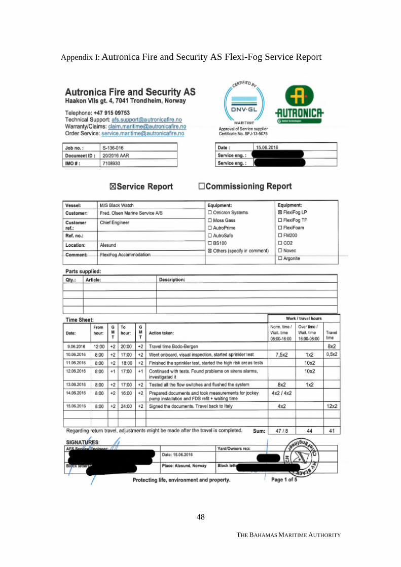
48
THE BAHAMAS MARITIME AUTHORITY
Appendix I: Autronica Fire and Security AS Flexi-Fog Service Report
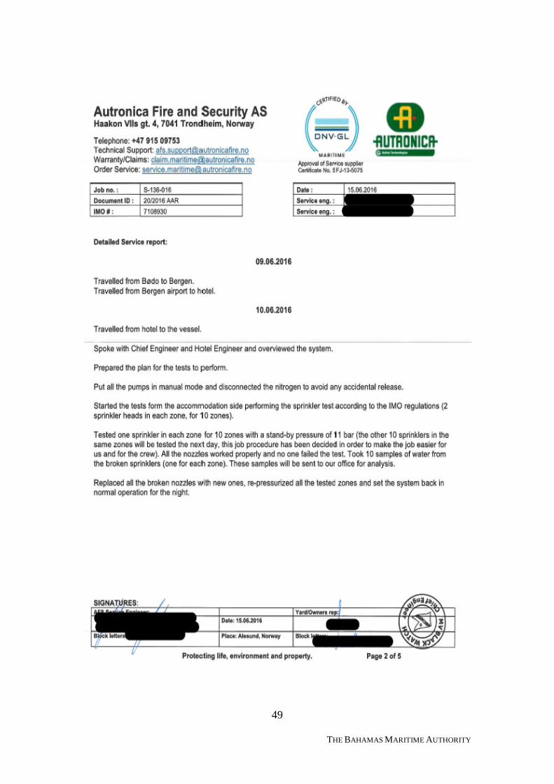
49
THE BAHAMAS MARITIME AUTHORITY
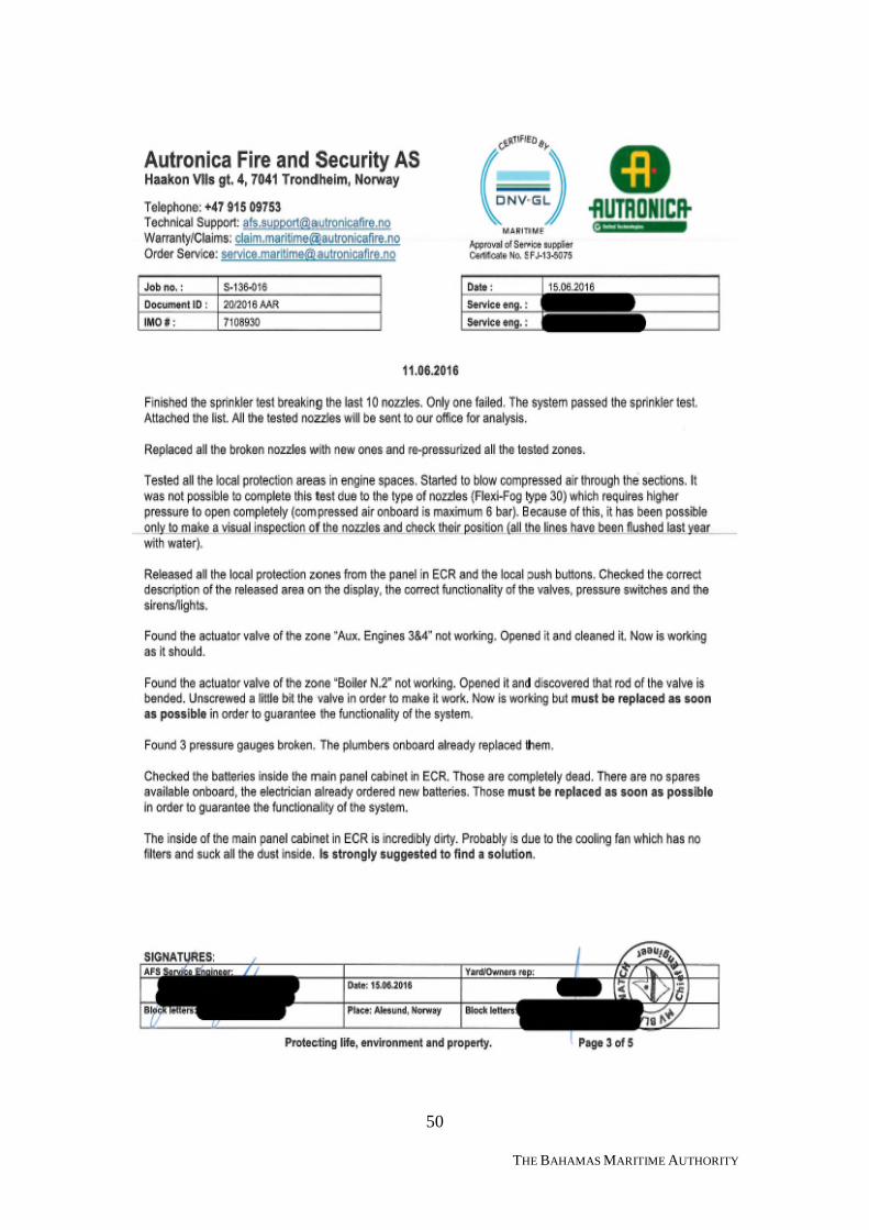
50
THE BAHAMAS MARITIME AUTHORITY
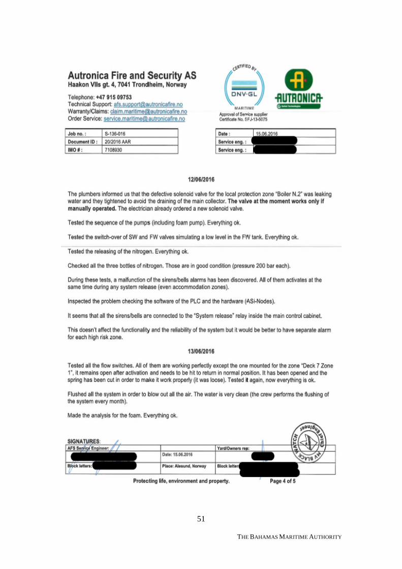
51
THE BAHAMAS MARITIME AUTHORITY
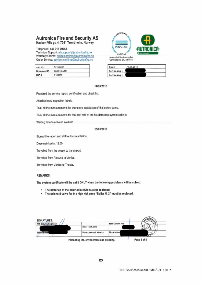
52
THE BAHAMAS MARITIME AUTHORITY
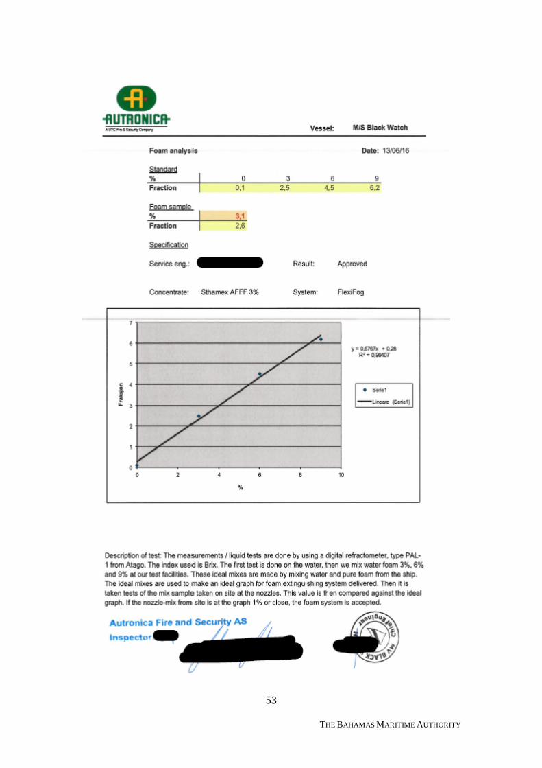
53
THE BAHAMAS MARITIME AUTHORITY
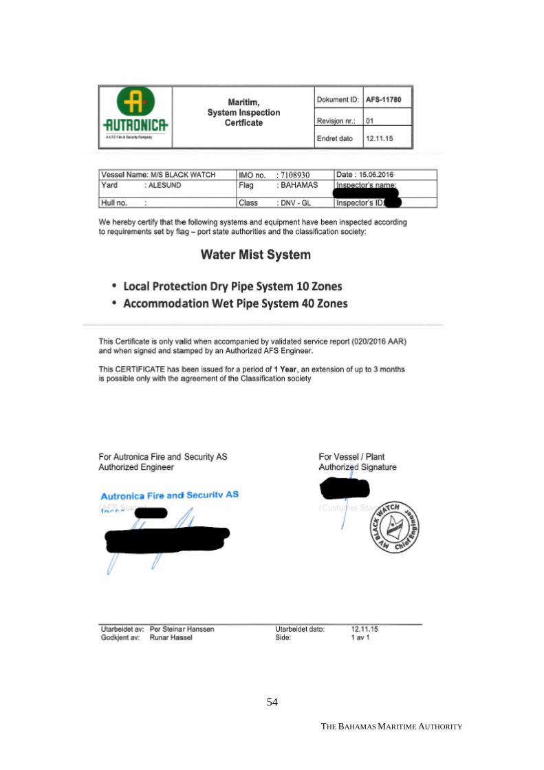
54
THE BAHAMAS MARITIME AUTHORITY
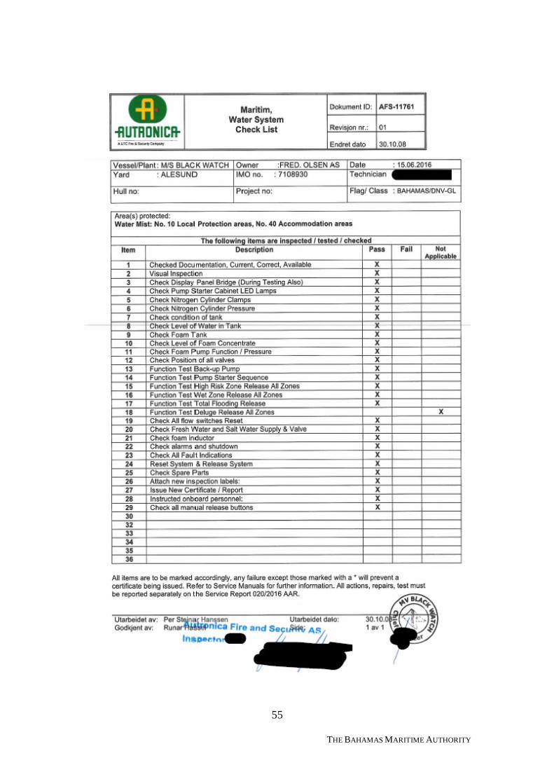
55
THE BAHAMAS MARITIME AUTHORITY
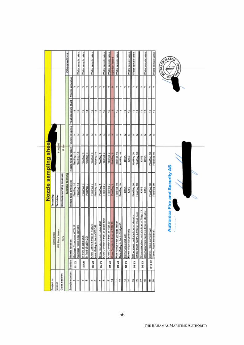
56
THE BAHAMAS MARITIME AUTHORITY
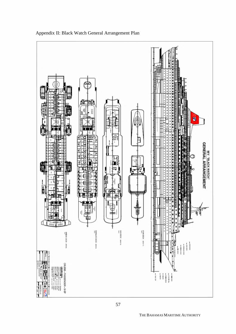
57
THE BAHAMAS MARITIME AUTHORITY
Appendix II: Black Watch General Arrangement Plan
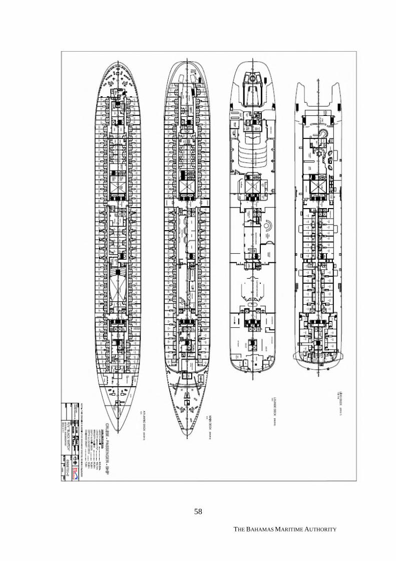
58
THE BAHAMAS MARITIME AUTHORITY
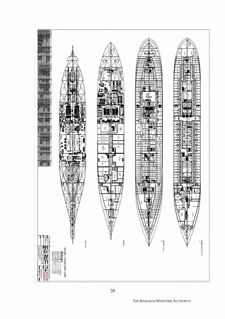
59
THE BAHAMAS MARITIME AUTHORITY
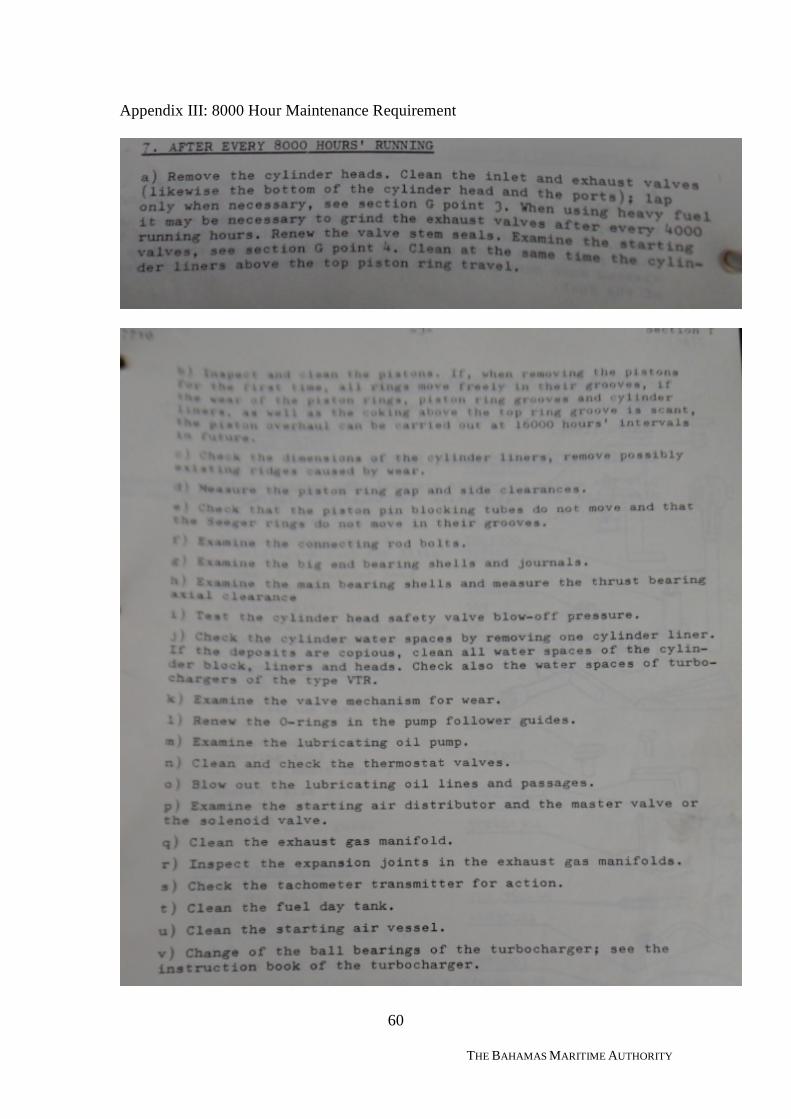
60
THE BAHAMAS MARITIME AUTHORITY
Appendix III: 8000 Hour Maintenance Requirement
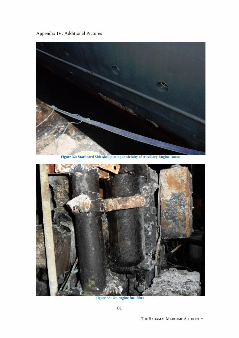
61
THE BAHAMAS MARITIME AUTHORITY
Appendix IV: Additional Pictures
Figure 32: Starboard Side shell plating in vicinity of Auxiliary Engine Room
Figure 33: On-engine fuel filter
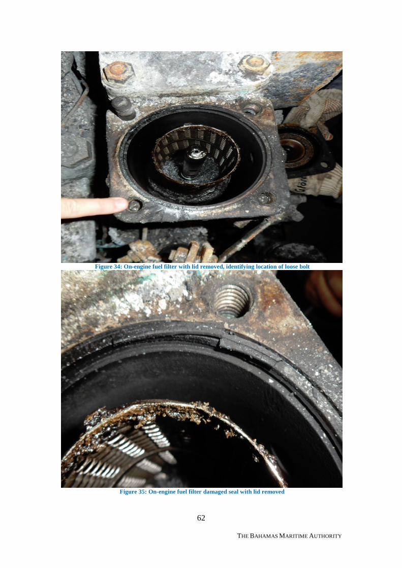
62
THE BAHAMAS MARITIME AUTHORITY
Figure 34: On-engine fuel filter with lid removed, identifying location of loose bolt
Figure 35: On-engine fuel filter damaged seal with lid removed
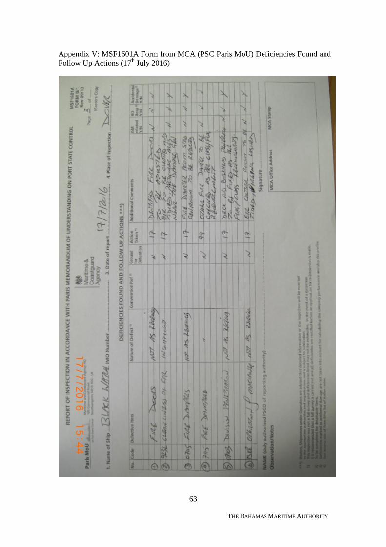
63
THE BAHAMAS MARITIME AUTHORITY
Appendix V: MSF1601A Form from MCA (PSC Paris MoU) Deficiencies Found andFollow Up Actions (17th July 2016)
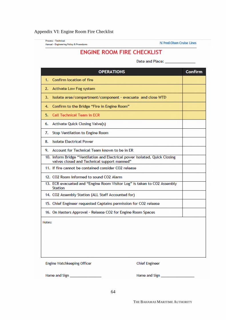
64
THE BAHAMAS MARITIME AUTHORITY
Appendix VI: Engine Room Fire Checklist