the ccv bible - shophemi.com€¦ · the ccv bible why a functional ... 3. your engine will run...
TRANSCRIPT
WWW.SHOPHEMI.COM
The CCV Bible Why a Functional Crankcase Ventilation System
Matters to You and Your High-Performance Engine
Mikah Barnett
11/9/2011
Often ignored, misunderstood, and bypassed without ceremony, the crankcase ventilation system on your engine plays a significant role in the performance, cleanliness, and reliability of your vehicle. Though important in any engine, the complexity and complications from improper functionality rise dramatically when forced induction is involved. This document explores what a CCV system is designed to do, how they function (both in theory and in reality), and guides you to the right components, plumbing, and understanding to get the most out of your particular vehicle.
Arrington Performance The CCV Bible 2 of 18
TABLE OF CONTENTS Introduction ................................................................................................................................................................... 3
Crankcase Ventilation 101 ............................................................................................................................................. 3
Blow-By: The Reason We’re Having This Discussion ..................................................................................................... 4
Piston Rings ............................................................................................................................................................... 4
What Is Blow-By Made Of? ....................................................................................................................................... 5
How Much Blow-By Is Generated? ............................................................................................................................ 6
CCV System Functions and Components ....................................................................................................................... 7
Flushing Dirty Air Out of the Crankcase .................................................................................................................... 7
Preventing the Buildup of Positive Crankcase Pressure ............................................................................................ 8
Ensuring Crankcase Gasses Exit The System as Clean(er) Air .................................................................................... 8
CCV System Standard Components ........................................................................................................................... 9
The Mighty Catch Can .................................................................................................................................................. 11
Building Your CCV System ............................................................................................................................................ 12
Make A Plan ............................................................................................................................................................ 12
Diagram Introduction .............................................................................................................................................. 13
Stage 1: Single Catch Can System, N/A Engine ........................................................................................................ 14
Stage 2: Double Catch Can System, N/A Engine ...................................................................................................... 15
Stage 3: Double Catch Can System, No PCV Valve .................................................................................................. 16
Stage 4: Dual Catch-Can System for Turbo or Centrifugal Superchargers .............................................................. 17
Stage 5: The Ultimate CCV System .......................................................................................................................... 18
Conclusion ................................................................................................................................................................... 18
Arrington Performance The CCV Bible 3 of 18
INTRODUCTION This document covers CCV systems in an abstract sense; the concepts included apply to a broad range of engine
applications from V8 race engines to turbocharged 4-cylinder engines and diesels. I’ll make every effort to keep
the information as general in scope as possible while providing enough detail to enable you to apply it to your
specific circumstances.
If you do not plan to read this whole document but instead are itching to skip to the “answers,” please just read
this part first. I will keep it brief.
Benefits of a fully functional CCV system over a removed, bypassed, undersized, or (most commonly) wrongly
plumbed system on a high-performance engine:
1. Your engine will make more horsepower
2. Your engine will produce less emissions (Mother Nature will thank you)
3. Your engine will run smoother and likely get improved gas mileage
4. Your intake system will be cleaner and happier
5. If you run an intercooler or charge cooler, it will stay cleaner and work more efficiently
6. Your engine compartment will stay cleaner
Reasons that the CCV system that came as original equipment on your vehicle may not be ideal:
1. It costs too much to have an ideal system in every car
2. The OEM system works perfectly fine for 90%+ of the driving that will be done with any particular car, but
10% of the time it’s less than ideal
3. You may have increased the performance of your vehicle or engine beyond what the OEM system was
ever intended to handle (as well you should)
4. The OEM system must work with no maintenance so that there is nothing to plug, clean out, level check,
or otherwise work on because people will just not do it (many barely change their oil)
So, skip ahead if you must, but know that if you run your engine hard, you WILL benefit from a properly
functioning CCV system. Also know that just because you have not done work to your engine does not mean it’s
ready to handle all the abuse you can throw at it. If you never run your engine at wide open throttle, never tow
anything with your truck, and never care if you’re getting maximum performance out of your engine, then you can
put this down now. If you care enough to make it right, then read on my friend.
CRANKCASE VENTILATION 101 A Google search for crankcase ventilation (CCV) system yields all kinds of interesting information. Much is
presented as fact, and some of it actually is. I will not go to great lengths to talk about where CCV systems came
from or why, suffice to say that they are installed on ALL new vehicle engines (diesel and spark-ignition alike) and
have been for decades. If you want to know more about this history, search away. Our focus is on how to make
the CCV system work for us.
The reason that every engine needs a CCV system is because of blow-by. Very simply put, because the piston rings
do not (and cannot) seal perfectly to the cylinder walls, every time there is a pressure difference between the
bottom of the piston and the top of the piston, some amount of gasses will leak past the rings. Because the vast
majority of a piston’s time it has higher pressure on top than on bottom, the net result is that some volume of air is
Arrington Performance The CCV Bible 4 of 18
flowing in to the crankcase past the rings any time the engine is running. How much blow-by is being generated
depends on a huge number of variables and will be discussed in more detail later, but for now suffice to say it IS
happening all the time.
Knowing that, we can say that the primary purpose of the CCV system is to manage the flow of air through the
crankcase of the engine. Conceptually, the CCV system is trying to accomplish three main goals while managing
this airflow:
1) To flush “dirty” air out of the crankcase and bring in cleaner air
2) To prevent the crankcase from becoming positively pressurized
3) To ensure that the dirty air that does come out of your crankcase does not simply fly off into the sky and
kill all the birds, but rather is routed back into your engine to be burned again and finally exit as clean(er)
exhaust gasses
While those are the basic functions of the CCV system, each one deserves a more in-depth look if we really want to
understand it. And, like so many things, the answers to how to make your CCV system work properly are found in
the myriad details about what it’s trying to accomplish and how. Before we look at how and why the CCV system
works to manage blow-by, let’s have a closer look at the what, why, and how of blow-by creation.
BLOW-BY: THE REASON WE’RE HAVING THIS DISCUSSION “I already know what blow-by is, get on with it!” you say. Well, that may well be the case but we need to look a
little deeper than blow-by being the stuff that goes past the piston rings. We’ve already started making blow-by
out to be the nemesis of clean, efficient, powerful engines so let’s look a little deeper into why it has to happen,
what blow-by is made of, and what volume of blow-by is normal in a variety of different engine types.
PISTON RINGS
I made a statement earlier that piston rings cannot seal perfectly against the cylinder wall. While there are several
reasons for this, the most important for our conversation is that rings necessarily include a gap between the ends
of the ring. When the engine is cold, this gap is wide open (albeit only a few tens of thousandths of an inch) and
blow-by generation is at its maximum as a
percentage of total air volume processed. But,
the cylinder walls, pistons, and rings heat up
relatively quickly since they are intimately in
contact with the heat-generating combustion
process.
Even when hot, however, some small gap will
remain between the ring ends which allows
gasses to pass through. There are also surface
variations between the cylinder bore and ring
that will allow some amount of gasses past. A
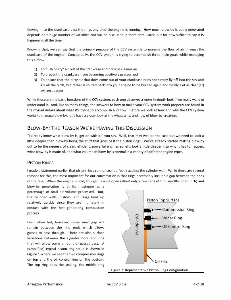
(simplified) typical piston ring setup is shown in
Figure 1 where we see the two compression rings
on top and the oil control ring on the bottom.
The top ring does the sealing, the middle ring
Figure 1: Representative Piston Ring Configuration
Arrington Performance The CCV Bible 5 of 18
helps seal but also scrapes oil from the wall of the cylinder on the down-stroke, and the bottom ring allows for oil
to come up the cylinder wall to lubricate the surface between the cylinder wall and the piston. There are a lot of
variations in the number of rings, shape, and function, but this is a representative setup.
Modern cylinder, piston, and ring designs are VERY effective at performing their jobs, but none of them are 100%
effective. When the top surface of the piston has more pressure than the bottom surface (which is the vast
majority of the time), gasses and fluids will leak past the rings and into the crankcase. Conversely, when the
pressure on the bottom surface of the piston is greater than on the top side (during the intake stroke, for
example), crankcase gasses and oil will try to bleed past the rings into the combustible area of the cylinder. This
effect is minimal because the pressure difference in this direction never gets very high – several PSI at most. We
won’t discuss “reverse blow-by” further because of this, just be aware that it can and does occur.
WHAT IS BLOW-BY MADE OF?
The ingredients list for blow-by does not contain a whole lot of things that you would voluntarily feed through your
high-performance engine:
1. Carbon monoxide (a combustion by-
product)
2. NOx (more combustion by-products)
3. Oxygen (not as much as clean air)
4. Nitrogen (again, not as much as clean
air)
5. Oil droplets – most of which are very
small (<5 micron droplet diameter)
6. Raw fuel (that blew by during
compression before combustion
occurred)
Of all the items in the list, the two that are most
near and dear to our topic are oil droplets and
unburned fuel. The oil is bad primarily because
when it leaves the crankcase as part of the blow-
by gas, it’s not going anywhere that we’d like to have oil; into the intake, across the intake valve, into the
combustion chamber, up onto the spark plug, etc.
One interesting note about oil droplets in blow-by gasses is that there are a lot more small ones (<5 micron droplet
diameter) than there are big ones. Increasing engine speed causes the droplets to tend further towards the small
size due to the faster speed of air moving inside the crankcase and the higher impact speeds with
rotating/translating parts inside. Most engines have some sort of oil separator integrated in to their design, but
for cost and simplicity these are typically “inertial” type separators which rely on the droplet of oil hitting
something in its path and sticking to that (called “impinging”) rather than going along with the flow. The problem
is that when droplets are very small (like the <5 micron drops we know are in blow-by), their aerodynamic drag is
greater than their inertia. So, rather than crash into the baffle of a separator and coalesce, they just follow the
airflow around it. We’ll talk more about this in the Air/Oil Separator discussion , but now seems as good a time as
any to make the point that most oil droplets in blow-by gas are really, really, REALLY small.
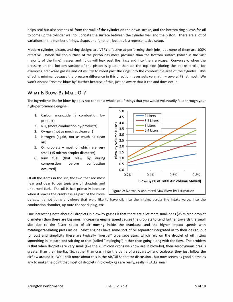
Figure 2: Normally Aspirated Max Blow-by Estimation
0.0
0.5
1.0
1.5
2.0
2.5
3.0
3.5
4.0
4.5
5.0
0.2% 0.4% 0.6% 0.8%
Blo
w-B
y V
olu
me
(C
FM)
Blow-By (% of Total Air Volume Moved)
2 Liters
3.5 Liters
5 Liters
6.4 Liters
Arrington Performance The CCV Bible 6 of 18
HOW MUCH BLOW-BY IS GENERATED?
Good question! The answer to this, like so many other questions is: “It depends.”
What does it depend on? Engine displacement, load, rpm, static compression ratio, combustion pressure,
volumetric efficiency, ring type, ring and cylinder bore condition, etc. A reasonable rule of thumb for an internal
combustion engine in good mechanical condition is about 0.5% of the total air displaced will escape past the rings
into the crankcase. Some engines will be below this, others will be above this. For all the experimental data I’ve
reviewed, the measured blow-by has fallen in a range between 0.3% and 0.8%. I’ve included a simple chart in
Figure 2 that shows the cubic feet per minute (CFM) of blow-by generated by engines of various displacements and
depending on what percentage of blow-by you assume is being experienced. The only way to know for sure
exactly what your particular engine is generating for blow-by is to take it to a chassis dyno that owns a blow-by
meter. These are relatively uncommon, but we
don’t need to know precisely anyway – this just
gives you a feel for the kinds of maximum values
you might be experiencing.
In order to simplify these charts, I had to remove
RPM from the variables list so I picked 5,000 RPM.
If your engine doesn’t or can’t turn that kind of
RPM, don’t worry about it because the volume of
blow-by depends much more on engine load
(higher load = greater blow-by volume) than it does
on RPM. More specifically, blow-by generation is
proportional to combustion pressure – anything
you do to increase combustion pressure will also
increase blow-by. I’m sure you forced-induction
guys realize I’m talking to you!
Volumetric efficiency (VE) is a ratio of the volume of
air that actually enters the cylinder during the
intake stroke compared to the maximum static volume of the cylinder. It’s another interesting topic that I won’t
cover here in detail, but it is possible to get a VE greater than 1 for a naturally aspirated engine. I picked 80% VE
for Figure 2 as it’s another good, round number that is generally applicable to production naturally-aspirated
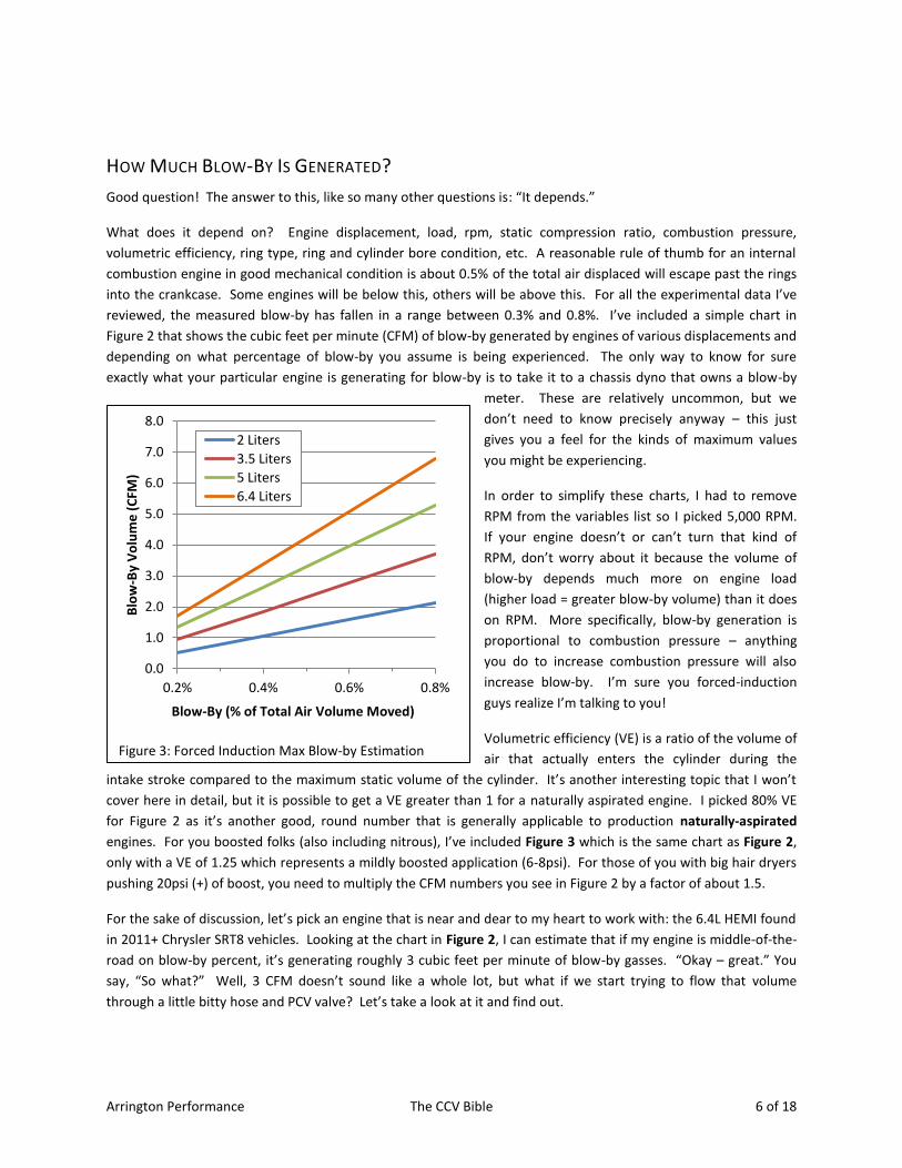
engines. For you boosted folks (also including nitrous), I’ve included Figure 3 which is the same chart as Figure 2,
only with a VE of 1.25 which represents a mildly boosted application (6-8psi). For those of you with big hair dryers
pushing 20psi (+) of boost, you need to multiply the CFM numbers you see in Figure 2 by a factor of about 1.5.
For the sake of discussion, let’s pick an engine that is near and dear to my heart to work with: the 6.4L HEMI found
in 2011+ Chrysler SRT8 vehicles. Looking at the chart in Figure 2, I can estimate that if my engine is middle-of-the-
road on blow-by percent, it’s generating roughly 3 cubic feet per minute of blow-by gasses. “Okay – great.” You
say, “So what?” Well, 3 CFM doesn’t sound like a whole lot, but what if we start trying to flow that volume
through a little bitty hose and PCV valve? Let’s take a look at it and find out.
Figure 3: Forced Induction Max Blow-by Estimation
0.0
1.0
2.0
3.0
4.0
5.0
6.0
7.0
8.0
0.2% 0.4% 0.6% 0.8%
Blo
w-B
y V
olu
me
(C
FM)
Blow-By (% of Total Air Volume Moved)
2 Liters
3.5 Liters
5 Liters
6.4 Liters
Arrington Performance The CCV Bible 7 of 18
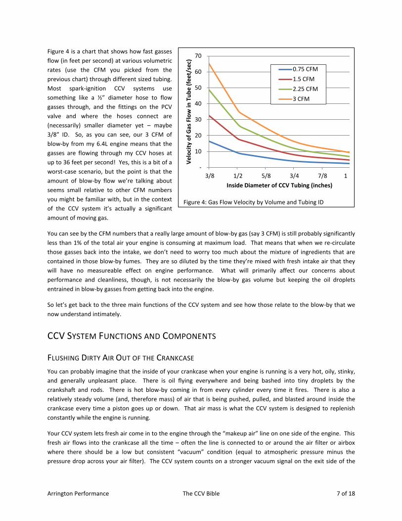
Figure 4 is a chart that shows how fast gasses
flow (in feet per second) at various volumetric
rates (use the CFM you picked from the
previous chart) through different sized tubing.
Most spark-ignition CCV systems use
something like a ½” diameter hose to flow
gasses through, and the fittings on the PCV
valve and where the hoses connect are
(necessarily) smaller diameter yet – maybe
3/8” ID. So, as you can see, our 3 CFM of
blow-by from my 6.4L engine means that the
gasses are flowing through my CCV hoses at
up to 36 feet per second! Yes, this is a bit of a
worst-case scenario, but the point is that the
amount of blow-by flow we’re talking about
seems small relative to other CFM numbers
you might be familiar with, but in the context
of the CCV system it’s actually a significant
amount of moving gas.
You can see by the CFM numbers that a really large amount of blow-by gas (say 3 CFM) is still probably significantly
less than 1% of the total air your engine is consuming at maximum load. That means that when we re-circulate
those gasses back into the intake, we don’t need to worry too much about the mixture of ingredients that are
contained in those blow-by fumes. They are so diluted by the time they’re mixed with fresh intake air that they
will have no measureable effect on engine performance. What will primarily affect our concerns about
performance and cleanliness, though, is not necessarily the blow-by gas volume but keeping the oil droplets
entrained in blow-by gasses from getting back into the engine.
So let’s get back to the three main functions of the CCV system and see how those relate to the blow-by that we
now understand intimately.
CCV SYSTEM FUNCTIONS AND COMPONENTS
FLUSHING DIRTY AIR OUT OF THE CRANKCASE
You can probably imagine that the inside of your crankcase when your engine is running is a very hot, oily, stinky,
and generally unpleasant place. There is oil flying everywhere and being bashed into tiny droplets by the
crankshaft and rods. There is hot blow-by coming in from every cylinder every time it fires. There is also a
relatively steady volume (and, therefore mass) of air that is being pushed, pulled, and blasted around inside the
crankcase every time a piston goes up or down. That air mass is what the CCV system is designed to replenish
constantly while the engine is running.
Your CCV system lets fresh air come in to the engine through the “makeup air” line on one side of the engine. This
fresh air flows into the crankcase all the time – often the line is connected to or around the air filter or airbox
where there should be a low but consistent “vacuum” condition (equal to atmospheric pressure minus the
pressure drop across your air filter). The CCV system counts on a stronger vacuum signal on the exit side of the
Figure 4: Gas Flow Velocity by Volume and Tubing ID
-
10
20
30
40
50
60
70
3/8 1/2 5/8 3/4 7/8 1
Ve
loci
ty o
f G
as F
low
in T
ub
e (
fee
t/se
c)
Inside Diameter of CCV Tubing (inches)
0.75 CFM
1.5 CFM
2.25 CFM
3 CFM
Arrington Performance The CCV Bible 8 of 18
system to pull dirty air out which, in turn, leaves a void that the clean air flows in to fill. So there are two sources
of gas coming IN to the crankcase: blow-by from the pistons and makeup air from a makeup air vent line. With the
exit vacuum controlling the pressure in the crankcase, the crankcase pressure should always be slightly below
atmospheric, what’s often referred to as a “slight vacuum.”
PREVENTING THE BUILDUP OF POSITIVE CRANKCASE PRESSURE
There are several good reasons why a slight vacuum is desirable in the crankcase. First and foremost, it keeps oil
leaks in check. With the air outside always pushing in (at least when the engine is running) rather than the oil
inside trying to push out, seals have a much easier time keeping the oil inside the engine where it belongs. Second
is that slightly lower pressure on the bottom side of the rings compared to the top side helps the rings seal better
against the piston lands.
So the idea here is quite simple: blow-by is pushing gasses at high pressure into your crankcase, and your engine
must therefore have a way to let an equivalent volume of gasses out so that you do not inflate the crankcase like a
balloon. Well, maybe that’s harsh, but here are some of the things that can and do happen when the crankcase
becomes positively pressurized:
1. The dipstick can blow out of the dipstick tube (this is great if you like car fires, BTW)
2. Oil can ooze out of every conceivable seal on the engine, including (but not limited to) rear main seal,
front main seal, valve cover seals, oil pan gaskets, front covers, etc.
3. Oil drains for turbochargers can stop draining or stop draining well because the crankcase is trying to push
the oil back towards the turbo
4. The engine can lose horsepower because of parasitic losses incurred as air from one cylinder is pushed
out on the down stroke and flows to fill the vacuum left by another piston that is on the upstroke. More
on this topic later as well.
5. Oil can have more of a tendency to flow UP past rings into the combustion area fouling spark plugs and
generally running amok
It is really important to note, when reading this little section, that having some vacuum pulling gasses out of the
crankcase is much better than letting the gasses push themselves out of the crankcase on their own. More
specifically, it is desirable that the pressure inside the crankcase remain lower than the pressure in any other part
of the engine air system – with the exception of the intake manifold when an engine is idling. In fact, this last
statement is why the PCV valve exists – more on that later.
ENSURING CRANKCASE GASSES EXIT THE SYSTEM AS CLEAN(ER) AIR
Blow-by has been a problem for all these reasons since the dawn of the Stone Age. Well, at least since the dawn of
the internal combustion engine. “Back in the day,” there was simply a tube from the top of the engine to
underneath the vehicle, and things were simple. Then, some enterprising engineers discovered that if they used a
venture from the moving car to pull a little vacuum on the end of that tube, they got even better engine
performance.
I threw that tidbit in partly because it shamelessly supports my other claims, but the reality is that the biggest
driver of CCV system evolution over the last several decades has been ever tightening emissions regulations.
Emissions considerations are the number 2 reason that we want to get blow-by gasses routed back through the
intake; the number 1 reason is that the intake is the simplest and most convenient source of the slight vacuum
Arrington Performance The CCV Bible 9 of 18
we’re looking for to get maximum performance from our engine. It is our good fortune that these two goals –
both important for different reasons – can be met with a single, simple solution.
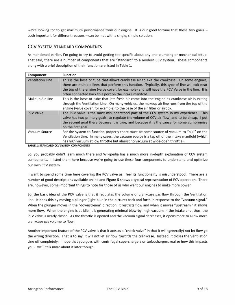
CCV SYSTEM STANDARD COMPONENTS
As mentioned earlier, I’m going to try to avoid getting too specific about any one plumbing or mechanical setup.
That said, there are a number of components that are “standard” to a modern CCV system. These components
along with a brief description of their function are listed in Table 1.
Component Function
Ventilation Line This is the hose or tube that allows crankcase air to exit the crankcase. On some engines, there are multiple lines that perform this function. Typically, this type of line will exit near the top of the engine (valve cover, for example) and will have the PCV Valve in the line. It is often connected back to a port on the intake manifold.
Makeup Air Line This is the hose or tube that lets fresh air come into the engine as crankcase air is exiting through the Ventilation Line. On many vehicles, the makeup air line runs from the top of the engine (valve cover, for example) to the base of the air filter or airbox.
PCV Valve The PCV valve is the most misunderstood part of the CCV system in my experience. This valve has two primary goals: to regulate the volume of CCV air flow, and to be cheap. I put the second goal there because it is true, and because it is the cause for some compromise on the first goal.
Vacuum Source For the system to function properly there must be some source of vacuum to “pull” on the Ventilation Line. In many cases, the vacuum source is a tap off of the intake manifold (which has high vacuum at low throttle but almost no vacuum at wide-open throttle).
TABLE 1: STANDARD CCV SYSTEM COMPONENTS
So, you probably didn’t learn much there and Wikipedia has a much more in-depth explanation of CCV system
components. I listed them here because we’re going to use these four components to understand and optimize
our own CCV system.
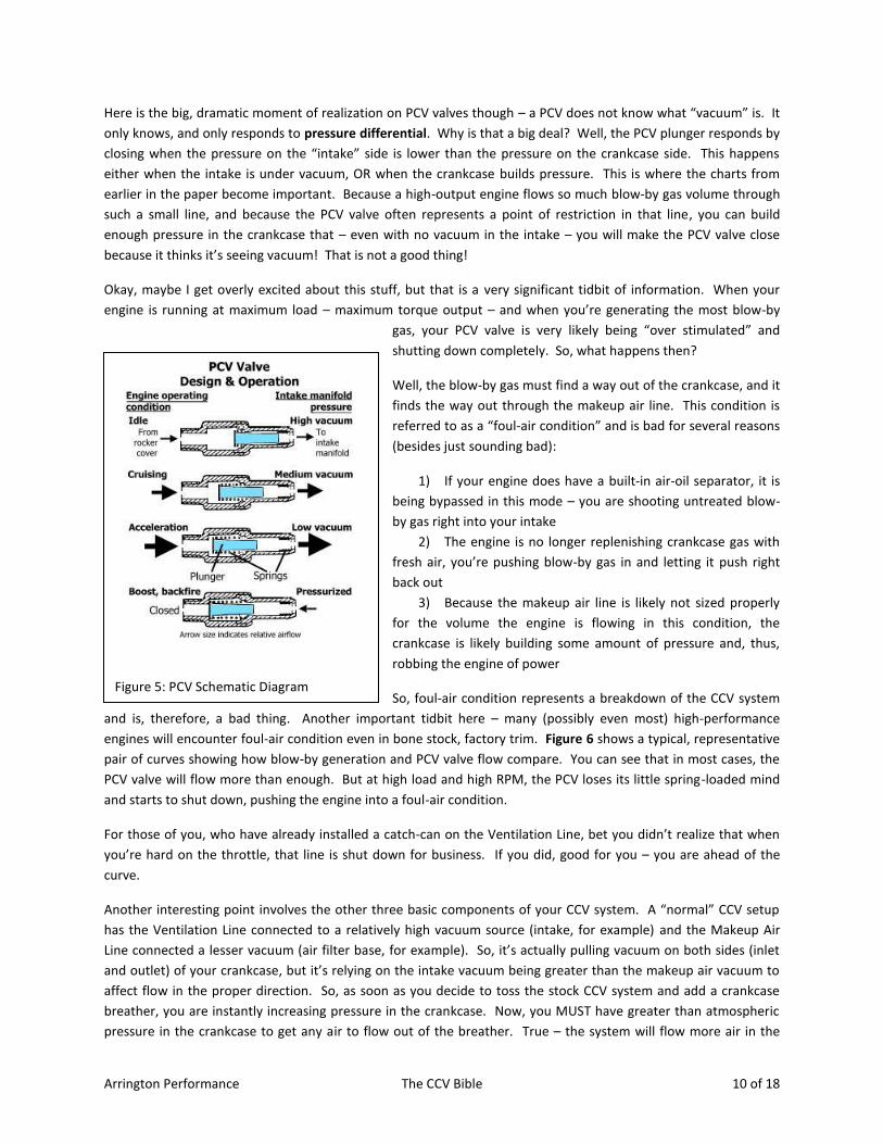
I want to spend some time here covering the PCV valve as I feel its functionality is misunderstood. There are a
number of good descriptions available online and Figure 5 shows a typical representation of PCV operation. There
are, however, some important things to note for those of us who want our engines to make more power.
So, the basic idea of the PCV valve is that it regulates the volume of crankcase gas flow through the Ventilation
line. It does this by moving a plunger (light blue in the picture) back and forth in response to the “vacuum signal.”
When the plunger moves in the “downstream” direction, it restricts flow and when it moves “upstream,” it allows
more flow. When the engine is at idle, it is generating minimal blow-by, high vacuum in the intake and, thus, the
PCV valve is nearly closed. As the throttle is opened and the vacuum signal decreases, it opens more to allow more
crankcase gas volume to flow.
Another important feature of the PCV valve is that it acts as a “check-valve” in that it will (generally) not let flow go
the wrong direction. That is to say, it will not let air flow towards the crankcase. Instead, it closes the Ventilation
Line off completely. I hope that you guys with centrifugal superchargers or turbochargers realize how this impacts
you – we’ll talk more about it later though.
Arrington Performance The CCV Bible 10 of 18
Here is the big, dramatic moment of realization on PCV valves though – a PCV does not know what “vacuum” is. It
only knows, and only responds to pressure differential. Why is that a big deal? Well, the PCV plunger responds by
closing when the pressure on the “intake” side is lower than the pressure on the crankcase side. This happens
either when the intake is under vacuum, OR when the crankcase builds pressure. This is where the charts from
earlier in the paper become important. Because a high-output engine flows so much blow-by gas volume through
such a small line, and because the PCV valve often represents a point of restriction in that line, you can build
enough pressure in the crankcase that – even with no vacuum in the intake – you will make the PCV valve close
because it thinks it’s seeing vacuum! That is not a good thing!
Okay, maybe I get overly excited about this stuff, but that is a very significant tidbit of information. When your
engine is running at maximum load – maximum torque output – and when you’re generating the most blow-by
gas, your PCV valve is very likely being “over stimulated” and
shutting down completely. So, what happens then?
Well, the blow-by gas must find a way out of the crankcase, and it
finds the way out through the makeup air line. This condition is
referred to as a “foul-air condition” and is bad for several reasons
(besides just sounding bad):
1) If your engine does have a built-in air-oil separator, it is
being bypassed in this mode – you are shooting untreated blow-
by gas right into your intake
2) The engine is no longer replenishing crankcase gas with
fresh air, you’re pushing blow-by gas in and letting it push right
back out
3) Because the makeup air line is likely not sized properly
for the volume the engine is flowing in this condition, the
crankcase is likely building some amount of pressure and, thus,
robbing the engine of power
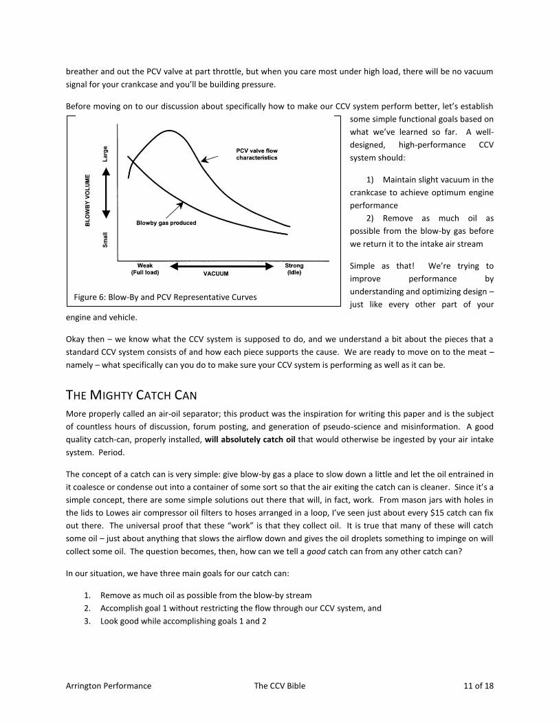
So, foul-air condition represents a breakdown of the CCV system
and is, therefore, a bad thing. Another important tidbit here – many (possibly even most) high-performance
engines will encounter foul-air condition even in bone stock, factory trim. Figure 6 shows a typical, representative
pair of curves showing how blow-by generation and PCV valve flow compare. You can see that in most cases, the
PCV valve will flow more than enough. But at high load and high RPM, the PCV loses its little spring-loaded mind
and starts to shut down, pushing the engine into a foul-air condition.
For those of you, who have already installed a catch-can on the Ventilation Line, bet you didn’t realize that when
you’re hard on the throttle, that line is shut down for business. If you did, good for you – you are ahead of the
curve.
Another interesting point involves the other three basic components of your CCV system. A “normal” CCV setup
has the Ventilation Line connected to a relatively high vacuum source (intake, for example) and the Makeup Air
Line connected a lesser vacuum (air filter base, for example). So, it’s actually pulling vacuum on both sides (inlet
and outlet) of your crankcase, but it’s relying on the intake vacuum being greater than the makeup air vacuum to
affect flow in the proper direction. So, as soon as you decide to toss the stock CCV system and add a crankcase
breather, you are instantly increasing pressure in the crankcase. Now, you MUST have greater than atmospheric
pressure in the crankcase to get any air to flow out of the breather. True – the system will flow more air in the
Figure 5: PCV Schematic Diagram
Arrington Performance The CCV Bible 11 of 18
breather and out the PCV valve at part throttle, but when you care most under high load, there will be no vacuum
signal for your crankcase and you’ll be building pressure.
Before moving on to our discussion about specifically how to make our CCV system perform better, let’s establish
some simple functional goals based on
what we’ve learned so far. A well-
designed, high-performance CCV
system should:
1) Maintain slight vacuum in the
crankcase to achieve optimum engine
performance
2) Remove as much oil as
possible from the blow-by gas before
we return it to the intake air stream
Simple as that! We’re trying to
improve performance by
understanding and optimizing design –
just like every other part of your
engine and vehicle.
Okay then – we know what the CCV system is supposed to do, and we understand a bit about the pieces that a
standard CCV system consists of and how each piece supports the cause. We are ready to move on to the meat –
namely – what specifically can you do to make sure your CCV system is performing as well as it can be.
THE MIGHTY CATCH CAN More properly called an air-oil separator; this product was the inspiration for writing this paper and is the subject
of countless hours of discussion, forum posting, and generation of pseudo-science and misinformation. A good
quality catch-can, properly installed, will absolutely catch oil that would otherwise be ingested by your air intake
system. Period.
The concept of a catch can is very simple: give blow-by gas a place to slow down a little and let the oil entrained in
it coalesce or condense out into a container of some sort so that the air exiting the catch can is cleaner. Since it’s a
simple concept, there are some simple solutions out there that will, in fact, work. From mason jars with holes in
the lids to Lowes air compressor oil filters to hoses arranged in a loop, I’ve seen just about every $15 catch can fix
out there. The universal proof that these “work” is that they collect oil. It is true that many of these will catch
some oil – just about anything that slows the airflow down and gives the oil droplets something to impinge on will
collect some oil. The question becomes, then, how can we tell a good catch can from any other catch can?
In our situation, we have three main goals for our catch can:
1. Remove as much oil as possible from the blow-by stream
2. Accomplish goal 1 without restricting the flow through our CCV system, and
3. Look good while accomplishing goals 1 and 2
Figure 6: Blow-By and PCV Representative Curves
Arrington Performance The CCV Bible 12 of 18
I count myself amongst those who don’t care much about goal 3, but looking at the aftermarket for catch cans
there is little doubt that looking good is as big a selling point as functionality (or bigger). So, I’ve included it here.
(Warning, unapologetic commercialism follows)
The new catch can we’ve developed at Arrington Performance was designed from the ground up to meet goals 1
and 2 above. I had to add a little consideration for goal 3 so that it could be sold, but its heart and soul is removing
oil from blow-by gas with minimum restriction to flow.
This patent-pending catch can design, which incorporates a spiral chamber with stainless mesh to catch large
droplets followed by an enclosed crankcase breather filter to catch smaller droplets will remove more oil than any
other can on the market right now. Additionally, it has large ½” NPT inlet and outlet ports that can support a true
5/8” diameter flow path. For a big cubic inch or high-boost engine, this is crucial.
One more important point is that the new Arrington catch can filters flow in both directions because it
incorporates a built-in crankcase breather filter. In this way, oil is removed when flowing the proper direction, but
when air is flowing backwards through the catch can, you don’t have to worry about debris getting pulled into the
crankcase.
(Now back to regularly scheduled programming)
Since I’m writing the paper and I get the only vote, I choose to define best catch can as meaning: the catch can
which removes the highest percentage of oil from the blow-by stream. You, on the other hand, get to define best
however you want and vote with your wallet. If you want the shiniest, or cheapest, or heaviest, or whatever catch
can then get that one. Regardless, get the best catch can(s) you can afford as they are your primary tool against
the evils of blow-by and foul-air condition.
BUILDING YOUR CCV SYSTEM
MAKE A PLAN
The first thing you need to do is to get organized about what your engine situation is, and where you plan on
taking it in the future. With CCV layout, there are several levels of complexity and cost, you need to figure out
which is right for your vehicle and your budget.
Adding a single catch can to a stock or lightly modified engine is a straightforward and well-known modification.
Normally installed on the Ventilation Line, the single catch can will work well right up until the engine is under
heavy load (as previously mentioned). At that point, the PCV valve will shut and all the crankcase air will vent out
through the Makeup Air Line instead. But, for the majority of street-driven cars, the total amount of oil missed by
not having a second catch can on the Makeup Air Line is minimal.
Anything above a very mild upgrade to a stock engine, demands a little more thought. If you are adding forced
induction – in particular a centrifugal supercharger or turbocharger – then you have even more to think about
because you lose your high vacuum source.
The very first thing you need to do before you buy anything is to familiarize yourself with your particular vehicles
CCV system. Identify the four components we talked about earlier and visualize how air flows through the
Arrington Performance The CCV Bible 13 of 18
crankcase at idle, part throttle, and wide open throttle. There are way too many variations for me to address
specifically here, but chances are you can figure it out or find the information online without much trouble.
DIAGRAM INTRODUCTION
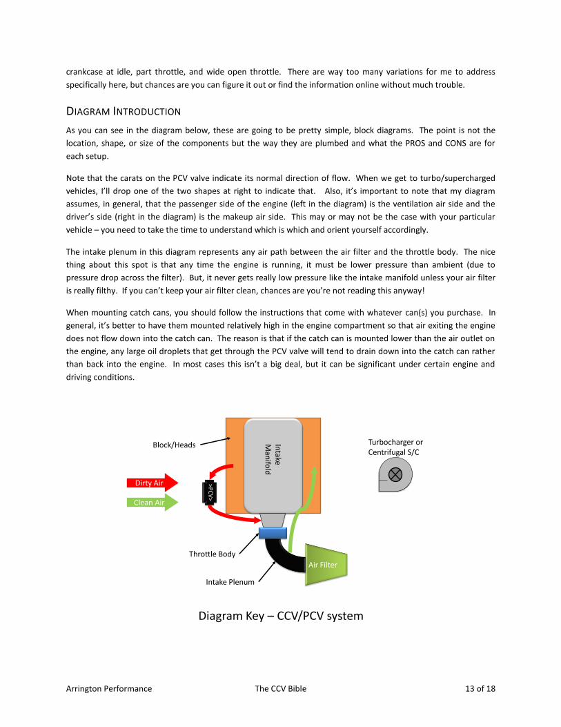
As you can see in the diagram below, these are going to be pretty simple, block diagrams. The point is not the
location, shape, or size of the components but the way they are plumbed and what the PROS and CONS are for
each setup.
Note that the carats on the PCV valve indicate its normal direction of flow. When we get to turbo/supercharged
vehicles, I’ll drop one of the two shapes at right to indicate that. Also, it’s important to note that my diagram
assumes, in general, that the passenger side of the engine (left in the diagram) is the ventilation air side and the
driver’s side (right in the diagram) is the makeup air side. This may or may not be the case with your particular
vehicle – you need to take the time to understand which is which and orient yourself accordingly.
The intake plenum in this diagram represents any air path between the air filter and the throttle body. The nice
thing about this spot is that any time the engine is running, it must be lower pressure than ambient (due to
pressure drop across the filter). But, it never gets really low pressure like the intake manifold unless your air filter
is really filthy. If you can’t keep your air filter clean, chances are you’re not reading this anyway!
When mounting catch cans, you should follow the instructions that come with whatever can(s) you purchase. In
general, it’s better to have them mounted relatively high in the engine compartment so that air exiting the engine
does not flow down into the catch can. The reason is that if the catch can is mounted lower than the air outlet on
the engine, any large oil droplets that get through the PCV valve will tend to drain down into the catch can rather
than back into the engine. In most cases this isn’t a big deal, but it can be significant under certain engine and
driving conditions.
Air Filter
>PC
V>
Turbocharger orCentrifugal S/C
Throttle Body
Block/Heads Intake
Man
ifold
Dirty Air
Clean Air
Diagram Key – CCV/PCV system
Intake Plenum
Arrington Performance The CCV Bible 14 of 18
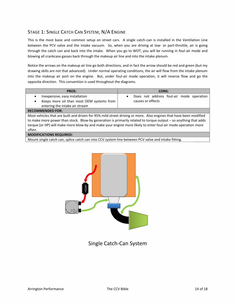
STAGE 1: SINGLE CATCH CAN SYSTEM, N/A ENGINE
This is the most basic and common setup on street cars. A single catch-can is installed in the Ventilation Line
between the PCV valve and the intake vacuum. So, when you are driving at low- or part-throttle, air is going
through the catch can and back into the intake. When you go to WOT, you will be running in foul-air mode and
blowing all crankcase gasses back through the makeup air line and into the intake plenum.
Notice the arrows on the makeup air line go both directions, and in fact the arrow should be red and green (but my
drawing skills are not that advanced). Under normal operating conditions, the air will flow from the intake plenum
into the makeup air port on the engine. But, under foul-air mode operation, it will reverse flow and go the
opposite direction. This convention is used throughout the diagrams.
PROS: CONS:
Inexpensive, easy installation
Keeps more oil than most OEM systems from entering the intake air stream
Does not address foul-air mode operation causes or effects
RECOMMENDED FOR:
Most vehicles that are built and driven for 95% mild street driving or more. Also engines that have been modified to make more power than stock. Blow-by generation is primarily related to torque output – so anything that adds torque (or HP) will make more blow-by and make your engine more likely to enter foul-air mode operation more often.
MODIFICATIONS REQUIRED:
Mount single catch can, splice catch can into CCV system line between PCV valve and intake fitting.
>PC
V>
Single Catch-Can System
Arrington Performance The CCV Bible 15 of 18
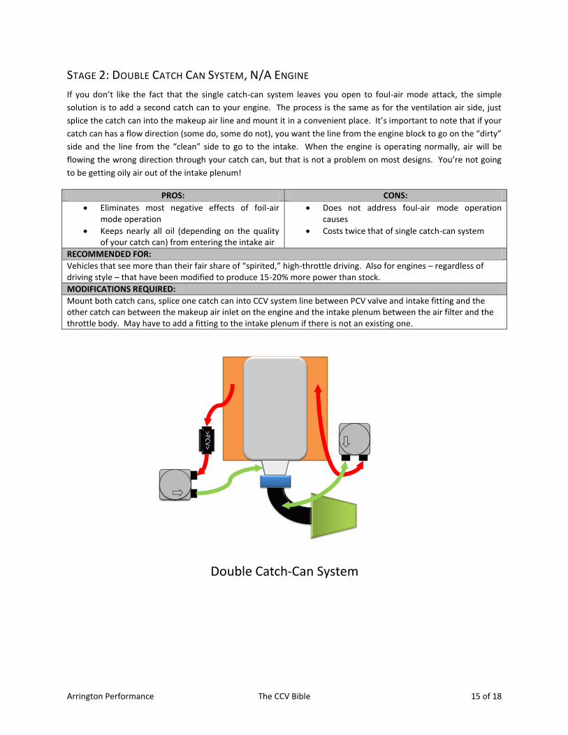
STAGE 2: DOUBLE CATCH CAN SYSTEM, N/A ENGINE
If you don’t like the fact that the single catch-can system leaves you open to foul-air mode attack, the simple
solution is to add a second catch can to your engine. The process is the same as for the ventilation air side, just
splice the catch can into the makeup air line and mount it in a convenient place. It’s important to note that if your
catch can has a flow direction (some do, some do not), you want the line from the engine block to go on the “dirty”
side and the line from the “clean” side to go to the intake. When the engine is operating normally, air will be
flowing the wrong direction through your catch can, but that is not a problem on most designs. You’re not going
to be getting oily air out of the intake plenum!
PROS: CONS:
Eliminates most negative effects of foil-air mode operation
Keeps nearly all oil (depending on the quality of your catch can) from entering the intake air
Does not address foul-air mode operation causes
Costs twice that of single catch-can system
RECOMMENDED FOR:
Vehicles that see more than their fair share of “spirited,” high-throttle driving. Also for engines – regardless of driving style – that have been modified to produce 15-20% more power than stock.
MODIFICATIONS REQUIRED:
Mount both catch cans, splice one catch can into CCV system line between PCV valve and intake fitting and the other catch can between the makeup air inlet on the engine and the intake plenum between the air filter and the throttle body. May have to add a fitting to the intake plenum if there is not an existing one.
>PC
V>
Double Catch-Can System
Arrington Performance The CCV Bible 16 of 18
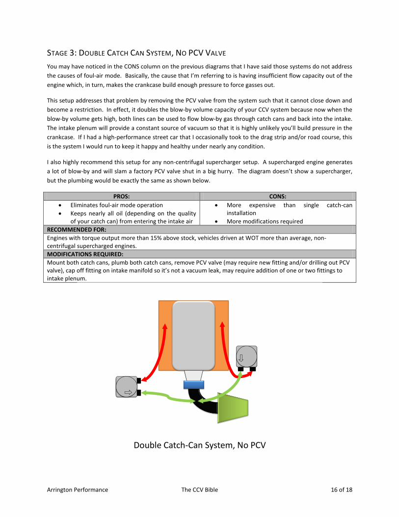
STAGE 3: DOUBLE CATCH CAN SYSTEM, NO PCV VALVE
You may have noticed in the CONS column on the previous diagrams that I have said those systems do not address
the causes of foul-air mode. Basically, the cause that I’m referring to is having insufficient flow capacity out of the
engine which, in turn, makes the crankcase build enough pressure to force gasses out.
This setup addresses that problem by removing the PCV valve from the system such that it cannot close down and
become a restriction. In effect, it doubles the blow-by volume capacity of your CCV system because now when the
blow-by volume gets high, both lines can be used to flow blow-by gas through catch cans and back into the intake.
The intake plenum will provide a constant source of vacuum so that it is highly unlikely you’ll build pressure in the
crankcase. If I had a high-performance street car that I occasionally took to the drag strip and/or road course, this
is the system I would run to keep it happy and healthy under nearly any condition.
I also highly recommend this setup for any non-centrifugal supercharger setup. A supercharged engine generates
a lot of blow-by and will slam a factory PCV valve shut in a big hurry. The diagram doesn’t show a supercharger,
but the plumbing would be exactly the same as shown below.
PROS: CONS:
Eliminates foul-air mode operation
Keeps nearly all oil (depending on the quality of your catch can) from entering the intake air
More expensive than single catch-can installation
More modifications required
RECOMMENDED FOR:
Engines with torque output more than 15% above stock, vehicles driven at WOT more than average, non-centrifugal supercharged engines.
MODIFICATIONS REQUIRED:
Mount both catch cans, plumb both catch cans, remove PCV valve (may require new fitting and/or drilling out PCV valve), cap off fitting on intake manifold so it’s not a vacuum leak, may require addition of one or two fittings to intake plenum.
Double Catch-Can System, No PCV
Arrington Performance The CCV Bible 17 of 18
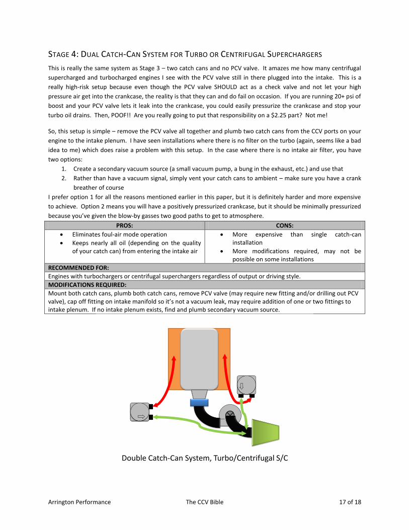
STAGE 4: DUAL CATCH-CAN SYSTEM FOR TURBO OR CENTRIFUGAL SUPERCHARGERS
This is really the same system as Stage 3 – two catch cans and no PCV valve. It amazes me how many centrifugal
supercharged and turbocharged engines I see with the PCV valve still in there plugged into the intake. This is a
really high-risk setup because even though the PCV valve SHOULD act as a check valve and not let your high
pressure air get into the crankcase, the reality is that they can and do fail on occasion. If you are running 20+ psi of
boost and your PCV valve lets it leak into the crankcase, you could easily pressurize the crankcase and stop your
turbo oil drains. Then, POOF!! Are you really going to put that responsibility on a $2.25 part? Not me!
So, this setup is simple – remove the PCV valve all together and plumb two catch cans from the CCV ports on your
engine to the intake plenum. I have seen installations where there is no filter on the turbo (again, seems like a bad
idea to me) which does raise a problem with this setup. In the case where there is no intake air filter, you have
two options:
1. Create a secondary vacuum source (a small vacuum pump, a bung in the exhaust, etc.) and use that
2. Rather than have a vacuum signal, simply vent your catch cans to ambient – make sure you have a crank
breather of course
I prefer option 1 for all the reasons mentioned earlier in this paper, but it is definitely harder and more expensive
to achieve. Option 2 means you will have a positively pressurized crankcase, but it should be minimally pressurized
because you’ve given the blow-by gasses two good paths to get to atmosphere.
PROS: CONS:
Eliminates foul-air mode operation
Keeps nearly all oil (depending on the quality of your catch can) from entering the intake air
More expensive than single catch-can installation
More modifications required, may not be possible on some installations
RECOMMENDED FOR:
Engines with turbochargers or centrifugal superchargers regardless of output or driving style.
MODIFICATIONS REQUIRED:
Mount both catch cans, plumb both catch cans, remove PCV valve (may require new fitting and/or drilling out PCV valve), cap off fitting on intake manifold so it’s not a vacuum leak, may require addition of one or two fittings to intake plenum. If no intake plenum exists, find and plumb secondary vacuum source.
Double Catch-Can System, Turbo/Centrifugal S/C
Arrington Performance The CCV Bible 18 of 18
STAGE 5: THE ULTIMATE CCV SYSTEM
Stage 5 is so cool and top secret that it doesn’t even get a diagram – now that’s cool. The plumbing in stages 3 and
4 is the way to go as far as putting the right hardware in the right places. The only thing that we didn’t cover – and
what makes Stage 5 so secretive and elusive – is increasing the total flow capacity of your system.
The simple fact is that larger tube/fitting diameter means you can flow more gasses with less chance of building
pressure. The ½” ID hoses (and smaller!) found on many OEM systems will not keep up with the blow-by
generated by some of the heavy breathing engines out there today. If you are spending thousands of dollars to
make your engine capable of things it was never intended to do, make sure to set aside a few bucks to increase the
size of the CCV outlets on the top of your engine. Then, use fittings, tubes, and catch cans that can accommodate
these larger flow paths.
Did I mention that the new Arrington Catch Can will support a true 5/8” flow path? Oh yes – I
believe I did!
I’m not going in to detail on Stage 5 because it really will depend on your particular engine and vehicle, but the
idea is simple. Just like you removed flow restrictions from your fuel system, you need to do the same for your
CCV system. Your whole engine will thank you for it.
CONCLUSION If you have made it this far into this paper, I hope you’ve learned some new things and are feeling ready to do
battle for truth and understanding the next time the catch can discussion comes up at your local cruise-in, club
meeting, or on your favorite forum.
The bottom line is that the CCV system on your engine is an important one and deserves the same level of care and
understanding you might show your fuel system, air filtration system, or ignition system. It’s not rocket science,
and there are simple things you can do – depending on the level of complexity of your build – to make sure your
CCV system is as high-performance as the rest of your car.
I would like to thank Arrington Performance for supporting this study and their sincere commitment to building a
better mousetrap around this so-often-ignored engine system.