test plans - nasa · the document provided contains the detailed test plans for ssto lightweight...
TRANSCRIPT
LDTPS-TP-1
Test Plans
Lightweight Durable TPSTasks 1, 2, 4, 5, and 6
Cooperative Agreement NCC2-9003
July 29, 1994
H. S. Greenberg, Prmcipa Investigator
il,Llt ROCkilVell Aerospace
Space Systems Division
https://ntrs.nasa.gov/search.jsp?R=19950005422 2020-03-14T21:01:29+00:00Z
Fo rewo rd:
The document provided contains the Detailed Test Plans for SSTOLightweight Durable TPS (Task 1,2, 4, 5, & 6). The format of this document isdisplayed in the "Test Plan Index" on the following page. As each Taskprogresses, it's Detailed Test Plan and it's associated appendices will bemaintained as "stand-alone" documents.
TEST PLAN INDEX
TASK TEST PLANS
Task I, Development of Fluted Core Flexible Blankets
Task 2, Advance Flexible TPS that Incorporates MLI
Task 4, TPS Attachment Methods
Task 5, TPS Robustness
Task 6, Integrated Health Monitoring
DTP 6446-801
DTP 6447-801
DTP 6448-801
DTP 6449-801
DTP 6450-801
APPENDICES, TEST SPECIFIC TEST PLANS
Appendix A,
Appendix B,
Appendix C
Appendix D
Appendix E
Appendix F
Appendix G
Appendix H
Appendix I,
Appendix J,
Appendix K,
Appendix L,
Arcjet facilities, 60 and 20 MW
Wind tunnel
Debris impact
Rain impact
Rain impact, single drop
Rain/wind
Salt Spray
Vibroacoustics
Vibration
Radiant exposure
Venting
Air Impingement
DTP 6451-810
DTP 6451-811
DTP 6451-812
DTP 6451-813
DTP 6451-814
DTP 6451-815
DTP 6451-816
DTP 6451-817
DTP 645 I-818
DTP 6451-819
DTP 6451-820
DTP 6451-822
Detail Test Plan - DTP 6446-801
Task 1 - Development of Fluted-Core Flexible Blankets
NRA8-12 - Advanced Structures and TPS TechnologiesNCC2-9003 - Cooperative Agreement
TA-3 - Lightweight Durable Thermal Protection System
Prepared by : Tina LuTask Leader: Mary Fleming
Draft - July 27, 1994
Table of Contents
DTP 6446-801
Page 2
Section
1.0 OBJECTIVE
2.0 BACKGROUND
3.0 GENERAL REQUIREMENT
4.0 SUBTASK DESCRIPTION
4.1 Fabric Structure Development
4.2 Insulation Material Development
4.3 Composite Development
4.4 Surface Architecture
4.5 Finished Composite Evaluation
4.6 Composite Processing
5.0 APPENDIX
3
3
4
5
6
11
13
15
16
2O
DTP 6446-801Page 3
1.0 OBJECTIVE
The objective of this task is to develop the fluted core flexible blankets, also referredto as the Tailorable Advanced Blanket Insulation (TABI), to a technology readinesslevel (TRL) of 6. This task is one of the six tasks under TA 3, Lightweight DurableTPS study, of the Single Stage to Orbit (SSTO) program. The purpose of this taskis to develop a durable and low maintenance flexible TPS blanket material to be
implemented on the SSTO vehicle.
2.0 BACKGROUND
This task is divided into 6 subtasks. This detail test plan (DTP) begins with a
general objective section, a general background section and a general requirementsection for the entire task, followed by details of each of the subtasks which containintroduction, applicable documents, detailed requirements, fabrication /test articledescription, fabrication / test procedures, sample data sheet, equipment, sketches /schematics and schedule. Some of the subtasks are fabrication tasks and the
sections are modified to reflect the nature of the subtask. In subtasks which requiretesting of the material, DTP of the test will be referenced and attached to in theAppendix section.
TABI is a next generation flexible TPS blanket material concept developed byNASA Ames a few years ago. It consists of 3-D fluted core structure integrallywoven with high temperature ceramic yarns and the flutes filled with hightemperature insulative ceramic material. NASA Ames awarded a contract to WovenStructures to weave various shapes of fluted cores, using various types of ceramicyarns. The weaving know-how, however, has since been lost due to contractcancellation and a change of Woven Structures ownership. The end result is thatTABI is not commercially available.
Advanced Flexible Reusable Surface Insulation (AFRSI) on the Shuttle orbiter hasdemonstrated the weight and thermal advantages of flexible blanket TPS.However, due to the irregular surface configuration of AFRSI and its maximum-temperature limitation, its application is limited to upper surfaces of the vehicle.TABI's list of attractive properties, on the other hand, include high temperaturecapability, smooth aerodynamic surfaces, ease of installation / replacement anddurability. These properties make TABI an attractive TPS candidate for the SSTOvehicle.
Since the original supplier of the TABI woven fabric configuration no longer exists,the primary goal of this task is to reestablish a commercial source for the TABI fabricstructures required for the test articles of this program. The development ofinsulation installation procedures and the characterization of the resulting flexiblethermal blanket are additional goals of this task.
The task is divided into 6 subtaskso They include developing the weaving of theTABI, batting insulation insertion techniques, the study for a strong, durable surfacearchitecture, the evaluation and material characterization of the finished TABI
composite, and the processing and installation procedures for the TABI blankets tobe implemented on the SSTO vehicle.
DTP 6446-801Page 4
3.0 GENERAL REQUIREMENT
3.1 Documentation
3.1.1 Detailed test Drocedure (DTP)
All testing will be conducted in accordance with this test procedure.
3.1.2 Laboratory Notebook
A Laboratory Notebook will be maintained by the Rockwell Responsible Test Engineer(RTE) depicting a complete test history. Test article configuration, instrumentation, testanomalies and all other pertinent data and information will be recorded.
3.1.3 Test Report
The test agency will issue a Laboratory Test Report (LTR). The test report will depict thecomplete test program, instrumentation, test procedures and results, test setup,photographs, test data and any other pertinent information.
3.2 Test Facility
Test equipment and facilities will be utilized at both government and industry facilities.Appropriate facilities will be selected to simulate the interaction of identified adverse
environments with specific TPS specimens fabricated in Task 4. Test facilities which havebeen identified are listed below.
• NASA-Ames arc jet facilities, 60 and 20 MW facilities• NASA-Ames light gas gun• AFWL rain impact facility• Rockwell cryogenic tank facility for ice/frost testing• Rockwell rain/wind facility
• Rockwell salt spray environment facility• Rockwell vibroacoustic facility• Rockwell radiant heat facility
Schedules and test requirements are defined in the detailed test description section of thisdocument.
3.3 Instrumentation
All measurement instrumentation shall be calibrated and have a decal showing a validcalibration date. A list of all test instrumentation will be maintained in a LaboratoryNotebook.
3.4 Test Conduct
The test program will be conducted under the direction of the task leader or a designatedrepresentative.
4.0 SUBTASK DESCRIPTION
This task in divided into six subtasks as listed below.
described in details in Sections 4.1 through 4.6.
• Fabric Structure development (4.1)• Insulation material development (4.2)• Composite development (4.3)• Surface architecture (4.4)• Finished composite evaluation (4.5)° Composite processing (4.6)
DTP 6446-801
Page 5
The subtasks will be
DTP 6446-801Page 6
4.1 Fabric Structure Development
4.1.1 Introduction
This sub-task involves development of all the weaving for TABI. Weaving will besubcontracted by Rockwell to a weaver on task-by-task basis. Three ceramicmaterials will be used: Nicalon, Tyranno, and Nextel 440. The plan is to reestablishthe triangular fluted-core blanket concept by producing Nicalon TABI, followed bydevelopment of Tyranno and Nextel 440 TABI. Part of the objective is to achieve adurable, strong TABI outer mold line (OML) surface which will endure theenvironment without the protection of ceramic coatings. The first approach is toselect three different, strongest weave architectures known to the fabric industry, toobtain a durable, strong TABI OML surface. The second approach is to developmethods to attach a metallic foil to the TABI OML surface. The last TABI article will
have metallic yarns woven into the surface of TABI which will provide a means forbrazing the metallic foil to the TABI.
4.1.2 Applicable Documents
• Proposal to NRA8-12 - Advanced Structures and TPS Technologies.
• Cooperative Agreement - NCC2-9003
• NASA Ames, "TABI Procurement Specification, #9SB-90001-XR16"
• Rockwell, Statement of Work for Procuring TABI, June 1994.
Calamito, D.P., "Development of Tailorabte Advanced Blanket Insulation for
Advanced Space Transportation Systems," NASA Contractor Report 177444,Contract NAS2-12253, April 1987
Calamito, D.P., "Tailorable Advanced Blanket Insulation UsingAluminoborosilicate and Alumina Batting," NASA Contractor Report 177527,Contract NAS2-112693, July 1989
• Sawko, P.M., "Flexible Thermal Protection Materials,"
• Sawko, P.M., "Tailorable Advanced Blanket Insulation,"
Sawko, P.M. and Tran D., "Effects of Weave Architecture on Aeroacoustic
Performance of Ceramic Insulation Blankets," Journal of Advanced Materials,p51-57, Oct. 1993
• Sawko, P.M., "Thermal Insulation Blanket Material," NASA Contractor Report166367, Contract NAS2-11094, June 1982
• Falstrup, D., "Double Layered Tailorable Advanced Blanket Insulation," NASAContractor Report 1666000, Contract NAS2-11351, May 1983
• Pusch, R.H., "Thermal Blanket Insulation for Advanced Space Transportation
Systems," NASA Contractor Report 177341, Contract NAS2-11718, Feb., 1985
DTP 6446-801Page 7
4.1.3 Requirements
This subtask is a fabrication task. The TABI material to be delivered by the weaverwill be inspected per the NASA Ames specification, "TABI ProcurementSpecification #9SP-90001-XR16". Tests to evaluate the qualification andperformance of the articles will be described in Section 4.5 "Finished CompositeEvaluation".
4.1.4 Fabrication/Test Article Descriptign
Total of eight scheduled deliveries from the weaver are to be made as listed below.
• Eight sq. ft. (24" x 48" x 0.5") of Nicalon TABI per NASA Ames specification "TABI
Procurement Specification #9SP-90001-XR16", angle interlock OML surface.
• Sixteen sq. ft. (24" x 96" x 1") of Nicalon TABI, same configuration as #1 except1" flute height, instead of 0.5".
• Ten sq. ft. (24" x 60" x 1") of first strong weave configuration using Tyranno
• Ten sq. ft. (24" x 60" x 1") of second strong weave configuration using Tyranno
• Ten sq. ft. (24" x 60" x 1") of third strong weave configuration using Tyranno
• Sixty sq. ft. (24" x 360" x 1") of selected strongest weave configuration TyrannoTABI
• Twenty sq. ft. (24" x 120" x 1") of the selected strongest weave configurationNextel 440 TABI
Twenty sq. ft. (24" x 120" x 1") of (either Tyranno or Nextel 440) TABI withmetallic yarn woven into surface to provide brazing medium for metallic foilattachment
4.1.5 Fabrication Develooment/Test Procedures
4.1.5.1 First Nicalon TABI
One piece of 8 sq. ft. (24" x 48" x 0.5") of TABI to be fabricated with Nicalon 600denier yarns per Ames specification "TABI Procurement Specification,#9SB-90001-XR16", with triangular fluted cores and angle interlock OML surface. The purpose ofthis article is to demonstrate the ability to weave TABI. The Nicalon yarns (producedby Nippon Carbon and distributed by Dow Corning in the U.S.) are provided byNASA Ames in this program. The fluted core concept was successfullydemonstrated by weaving with Nicalon and some other ceramic materials in theprevious programs, and Nicalon was one of the materials that has the bestproperties and performance. Total of 40 pounds of Nicalon fibers were requested bythe weaver, Textile Product Incorporated (TPI), to fabricate both the first and secondNicalon TABI articles. It's estimated to take 3 months to complete the first Nicalon
TABI. The Nicalon yarns will be rayon served to be protected during the weaving
process.
DTP 6446-801Page 8
This article will be evaluation per the NASA Ames specification, arc jet, mini windtunnel, guarded hot plate, and vibroacoustic testing after the batting is inserted andthe TABI composite heat cleaned. The go-ahead to fabricate the second article of1" height Nicalon TABI will be based on the performance of this article. The detailsof the testing are discussed in Section 4.5.
4.1.5.2 Second Nicalon TABI
One piece of 16 sq. ft. (24" x 96" x 1") of Nicalon TABI will be fabricated. Thepurposes of this article are to scale the Nicalon TABI flute height from 0.5" to 1" andalso to obtain additional material for evaluation. One month is estimated for thefabrication of this article.
Tests TBD will be performed on this TABI. Details are discussed in Section 4.5.
4.1.5.3 Three Tyranno TABI with Different Weaves
Ten sq. ft. (24" x 60" x 1") of each of 3 different weave configuration Tyranno TABI(total of 30 sq. ft.) are to be fabricated. Rockwell is to research and purchase theappropriate Tyranno yarns. Ube Industries is the Japanese manufacturer of thematerial. The U.S. distributor is Textron Specialty Materials. Stu_ly and research isto be performed to select three strongest (or tightest) weaves for fabrics. Thepurpose of this task is to produce TABI with Tyranno yarn and to develop a strongOML fabric weave which does not require the protection of ceramic coatings. Theblack color of Tyranno and Nicalon, which provides high emittance, gives them anadvantage over other ceramic yarns. Tyranno is very similar to Nicalon incomposition except it has titanuim in addition to carbon, and silicon. It has a smallerdiameter than Nicalon and was assumed to be less health hazardous than Nicalon.
It is estimated that two months will be required to fabricate each of the three differentweaves Tyranno TABI.
Mini wind tunnel, air impingement (for screening purpose), and arc jet tests are tobe performed to determine the strongest weave configuration before proceeding tofabricate the remaining articles.
4.1.5.4 Strongest Weave Tyranno TABI
Sixty sq. ft. (24" x 360" x 1") of selected strongest weave configuration Tyranno TABI
will be fabricated. The purpose of this task is to provide the strongest weave forevaluation. Again, it is estimated that two months will be required for the fabricationof this article.
A series of tests (detailed in 4.5) will be performed to evaluate the performance ofthis strongest weave Tyranno TABI.
4.1.5.5 Nextel 440 TABI
Twenty sq. ft. (24" x 120" x 1") of the selected strongest weave configuration TABIwill be woven with Nextel 440. The purpose of this task is to produce Nextel 440TABI for comparative evaluation with Tyranno and Nicalon TABI. The schedule isthree months for the delivery of this article.
DTP 6446-801Page 9
Tests to evaluate the performance of Nextel 440 TABI will be determined laterbased on the performance of the uncoated strongest weave Tyranno.
4.1.5.6 TABI with Metallic Yarn Woven into OML Surface
Twenty sq. ft. (24" x 120" x 1") of either Tyranno or Nextel 440 TABI with metallicyarn woven into surface to provide brazing medium to metallic foil attachment willbe fabricated. The configuration is also referred to as DuraTABI. The estimatedtime is three months to complete the weaving.
Tests TBD will be performed to evaluate the concept of DuraTABI (see Section 4.5).
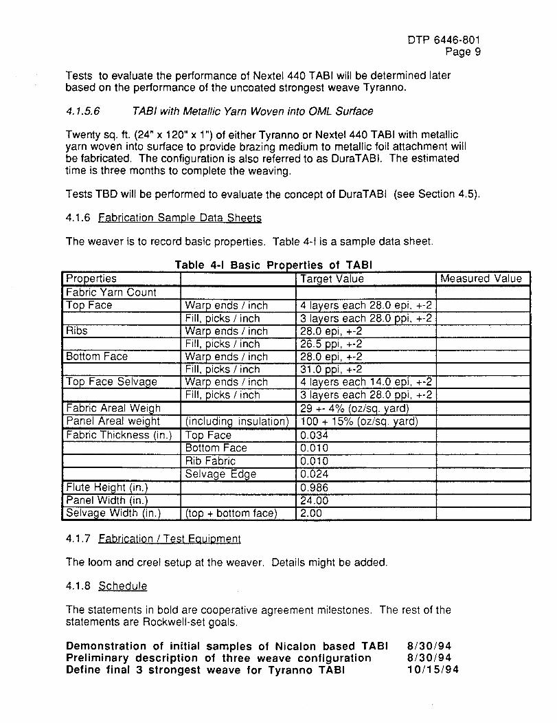
4.1.6 Fabrication Sample Data Sheets
The weaver is to record basic properties. Table 4-1 is a sample data sheet.
PropertiesFabric Yarn Count
Top Face
Ribs
Bottom Face
Top Face Selvage
Fabric Areal Weigh
Panel Areal weightFabric Thickness (in.)
Flute Height (in.)Panel Width (in.
Selvage Width (in.)
Table 4-1 Basic Pro)erties of TABI
Target Value Measured Value
Warp ends /inch
Fill, picks /inch
Warp ends / inchFill, picks /inch
Warp ends / inch
Fill, picks /inch
Warp ends /inch
Fill, picks /inch
(includinc,:) insulation)
Top FaceBottom Face
4 layers each 28.0 epi, +-2
3 layers each 28.0 ppi, +-2
28.0 epi, +-2
26.5 ppi, +-228.0 epi, +-2
31.0 ppi, +-2
4 layers each 14.0 epi, +-2
3 layers each 28.0 ppi, +-2
29 +- 4% (oz/sq. yard)
100 + 15% (oz/sq. yard)0.034
0.010
Rib Fabric 0.010
Selvacje Edc,:je 0.0240.986
24.00
(top + bottom face) 2.00
4.1.7 Fabrication / Test EauiDment
The loom and creel setup at the weaver. Details might be added.
4.1.8 Schedule
The statements in bold are cooperative agreement milestones. The rest of thestatements are Rockwell-set goals.
Demonstration of initial samples of Nicalon based TABIPreliminary description of three weave configurationDefine final 3 strongest weave for Tyranno TABI
8/30/948/30/9410/15/94

Produce additional Nicalon TABI for evaluation
Initiate first strong weave Tyranno TABIInitiate second strong weave Tyranno TABIInitiate third strong weave Tyranno "rABIInitiate production of 60 sq. ft. of strongest weave Tyranno TABIDevelopment of strongest weave Nextel 440 TABIProduce TABI with metallic thread
DTP 6446-801
Page 1010/15/9412/23/942/15/954/30/947/15/9511/30/954/30/96
DTP 6446-801Page 11
4.2 Insulation Material Development
4.2.1 Introduction
This task includes evaluation of batting insulation material options (the candidatematerials now are Nextel 440 and Saffil), development of cutting techniques oninsulation materials and batting insertion techniques into the TABI woven structure,development of a process adaptable to large-scale production, and demonstrationof techniques on 100 sq. ft. of woven TABI fabric structures.
4.2.2 AoDlicable Documents
Same as in Section 4.1.
4.2.3 Reauirement8
After the batting is inserted, the TABI composite (fluted core fabric structure plus thebatting material) should have smooth OML and IML surfaces, and an uniform
distribution of batting material to fully fill the TABI fluted core structure after heatclean. The requirement for the batting materials is to spring back after the binder isremoved to fill 0.5" flute height for the first Nicalon TABI, and to fill 1" flute height forthe remaining articles. The desired density of the batting material is 6 pounds percubic foot (pcf) after the organic binder is burned off. Tests to be performed on theTABI composites are described in the later section (4.5).
4.2.4 Fabrication /Test Article Description
At least 100 sq. ft. of stuffed TABI, including Nicalon, Tyranno, Nextel 440 and TABIwith metallic yarn in OML surface will be fabricated. Half of each kind of TABI will be
stuffed with Nextel 440 batting (supplied by 3M) and half with Saffil (supplied byZircar), unless one material was proven to perform unsatisfactory at the earlydevelopmental stage.
4.2.5 Fabrication Development ?Test Procedure
4.2.5.1 Obtain Batting Materials
Supplier rigidized Saffil - Zircar Products
Supplier rigidized Nextel 440 - 3MRockwell rigidized Nextel 440Rockwell rigidized Saffil
4.2.5.2 Combining Layers / Rigidizing / Compression Methods
Binder: acrylic Carboset (B. F. Goodrich Co.) diluted with deionized water atratios 1:2, 1:4, 1:5, 1:6 or 1:8 - saturate or spray
Combine layers "comb" method, followed by press and binderFabricate racks/contai ners/spacersCompression with Pneumatic press to spacer height for 2 hours
Dry in oven at 200OF for ~2.5 hours
DTP 6446-801Page 12
Record recovered height
4.2..5.3 Experiment with CuttersTable sawPneumatic hand held cutterUltrasonic knife
Regular knifeDiamond tipped circular bladeWire sawsKnife blade
4.2.5.4 Fabricate Tools for Cutting Desired Angles (if necessary)
60 o for unrigidized battingCalculated angles for rigidized batting
4.2.5.5 Developing Tool for insertion
Fabricate >24" long mandrels (tapered head) to be attached to the front oftriangular batting for ease of insertion
Triangular polyester / Mylar envelopes/Scotch tape for maintaining shape andeasier insertion, or
4 ml thick polyester or Mylar which can be formed into and maintain thetriangular shape to wrap around cut batting and can be removed after insertionFabricate tapered hollow nylon mandrel (For inserting batting withoutdamaging TABI fabrics) to be attached to front of Mylar wrapped batting
4.2.5.6 Heat clean
In air-circulated oven at 850OF for 4 hours to burn off binder, yarn lubricants,sizing and servings
4.2.6 Schedule
The insertion techniques will be fully developed by 10/15/94. The remaining effortof this subtask is to perform batting insertion for the eight TABI articles to bedelivered by the weaver.
The statements in bold are cooperative agreement milestones. The rest of thestatements are Rockwell-set goals.
Demonstrate TABI insulation insertion processInsert batting into the first 0.5" Nicalon TABIInsert batting into the second 1" Nicalon TABIInsert batting into first weave of Tyranno TABIInsert batting into second weave of Tyranno TABIInsert batting into third weave of Tyranno TABI
Insert batting into strongest weave Tyranno TABIInsert batting into Nextel 440 TABI
Insert batting into TABI with metallic yarn (assuming brazinghappens after stuffing)
10/15/9410/15/9411/27/94
2/15/954/30/956/30/95
8/31/9512/15/953/15/94
DTP 6446-801Page 13
4.3 Composite Development
4.3.1 Introduction
Stuffed TABI composite as the result of the previous two subtasks will be heatcleaned, and the outer surface smoothness, uniformity, weight and compressioncharacteristics will be evaluated in this subtask.
4.3.2 Applicable Documents
Same as in 4.1.
• ASTM-D-1372 Testing Package Cushioning Materials
4.3.3 Detailed Requirements
Uniform batting distribution which fully fills up the TABI fluted core structure with noair pockets as heat paths after heat clean, smooth TABI composite OML and IMLsurfaces, achieving desired final density and weight of the stuffed TABI compositeare requirements of this subtask.
4.3.4 Fabrication /Test Article Description
The TABI composites will be the result of the previous two subtasks.
4.3.5 Test Procedure
4.3.5. 1 Heat clean
850OF for 4 hours in an air-circulated oven to burn off binder, yarn lubricants, sizing
and servings.
4.3.5.2 Smoothness / density / weight/uniformity
The smoothness and uniformity of the TABI composite will be visually inspected andmeasured by thickness gauges after heat clean..
4.3.5.3 compression: strength / recovery
This test will be conducted on the selected strongest weave Tyranno TABI.
4.3.5.3.1 Specimens Description
Fabricate six specimens 6" x 6" strongest weave Tyranno TABI, three with Saffilbatting and three with Nextel 440 batting. Process and bond to 8" x 8" x 1/2"aluminum plates per MA0606-317. Heat clean and waterproofed with Z6070.
4.3.5.3.2 Test Procedures
Set up in the MTS test machine and perform test per ASTM-D-1372 (TestingPackage Cushioning Materials). Record drift and set.
DTP 6446-801Page 14
The original thickness will be established on each specimen under a load of 0.025psi. The specimens are then cycled 0.025 to 25 psi for 100 cycles, making thehysteresis graph recording for the first, 25th, 50th, 75th, and the 100th cycle. Thespecimen thickness will also be measured after each of the aforementioned cyclesunder 0.025 psi and recorded as compressed thickness. After the compressioncycling test is completed, the specimens will be allowed to recover unrestricted for24 hours. At the end of the recovery period each specimen is loaded to 0.025 psiand remeasured for recovered thickness. This test will be repeated after a TBDamount of time.
4.3.6 Schedule
The schedule of this subtask involves heat cleaning, evaluation of smoothness,uniformity and measurement of density of the TABI composites. Compression testwill be performed on the strongest weave of Tyranno TABI.
The statements in bold are cooperative agreement milestones. The rest of thestatements are Rockwell-set goals.
Heat clean (H/C), smoothness, density, uniformity of 1st 0.5" Nicalon TABIH/C, smoothness, density, uniformity of 2nd 1" Nicalon TABI
H/C, smoothness, density, uniformity of 1st weave Tyranno TABIH/C, smoothness, density, uniformity of 2nd weave Tyranno TABIH/C, smoothness, density, uniformity of 3rd weave Tyranno TABIH/C, smoothness, density, uniformity and compression test ofstrongest weave Tyranno TABIH/C, smoothness, density, uniformity of Nextel 440 TABI
H/C, smoothness, density, uniformity of TABI with metallic yarn
10/15/9411/27/94
2/15/954/30/956/30/95
8/31/95
12/15/953/15/96
DTP 6446-801Page 15
4.4 Surface Architecture
4.4.1 Introduction
This subtask is a joint effort between Rockwell and NASA Ames to attach metallicfoil to the OML surface of TABI composites, it is also referred to as DuraTABI. NASAAmes will develop and provide concepts and techniques of metallic foil attachmentto TABI. Rockwell will perform application of metallic foil attachment techniques toTABI.
4.4.2 ADDlicable Documents
Letter from T. Khaled (Rockwell) to D. Kourtides (ARC) discussing brazing optionsand limitations, Apr. 1994.
4.4.3 Detailed Requirements;
TBD
4.4.4 Test Article Description
TBD
4.4.5 Test Procedure
Wind tunnel and arc jet tests will be performed to examine the performance ofDuraTABI concept. More tests could be added depending on the results.Details of the tests are described in Section 4.5.
• Development of means for Non-destructive Testing (NDT) to inspect theadequacy of braze joints.
• Metallographic evaluation of braze joints.
4.4.6 Schedule
The statements in bold are cooperative agreement milestones. The rest of thestatements are Rockwell-set goals.
Metallic surface TABI development 4/30/96
DTP 6446-801
Page 16
4.5 Finished Composite Evaluation
4.5.1 Introduction
TAB! composite blankets will be evaluated for surface durability, thermal andphysical properties, venting and corrosion characteristics (for DuraTABI) in thissubtask. The tests for evaluation in this subtask include plasma arc, wind tunnel,debris impact, rain erosion, vibroacoustics, radiant exposure, venting, and airimpingement. The thermal and physical properties to be determined includeemittance, absorptance, specific heat, their changes after thermal exposures,thermal conductivity and surface catalysity. The corrosion resistant of the DuraTABImetallic foil will be determined by the salt fog test.
4.5.2 ADolicable Documents
To be specified in each of the tests listed below or in the DTP's in the Appendixsection.
4.5.3 Detailed Requirements
To be specified in each of the tests listed below or in the DTP's in the Appendixsection.
4.5.4 Detailed Test Article/Test Specimen Description
To be specified in each of the tests listed below or in the DTP's in the Appendixsection.
4.5.5 Test Procedure
This evaluation subtask is divided into five phases. The first phase is todemonstrate that the Nicalon TABI is reestablished. Tests will include arc jet,guarded hot plate, mini wind tunnel, vibroacoustics and any tests called out in theAmes specification. Test specimens will be 0.5 Nicalon, one set with Saffil batting,and the other set with Nextel 440 batting.The second phase of this subtask is to select the strongest weave among the threedifferent Tyranno weaves. Tests will include mini wind tunnel, air impingement (forscreening purpose), and arc jet test to determine the most durable, strongest weave.The test specimens will be six sets, two with each weave configuration, stuffed withSaffil batting in one set and Nextel 440 batting in the other.
The third phase is to evaluate the selected strongest weave Tyranno TABI. This isthe phase of the subtask that involves most of the tests. They include plasma arc,wind tunnel, debris impact test, rain erosion, vibroacoustics, radiant exposure, andair impingement, measurements for emittance, absorptance, specific heat, thechange of properties after thermal exposures, guarded hot plate for thermal
conductivity, plasma arc for catalysity, and compression test. The test specimenswill be the selected strongest weave Tyranno with two types of batting, Saffil andNextel 440.
The fourth phase is the evaluation of Nextel 440 TABI and the fifth phase is the
DTP 6446-801Page 17
evaluation of TABI with metallic foil attached (DuraTABI). The tests for both of thesephases are TBD depending on the results of the strongest weave Tyranno TABI.
The tests mentioned in the earlier paragraphs are listed below. Details such as thespecimen sizes, configurations, test parameters will be added.
4.5.5.1 Plasma arc, 20MW and 60 MW, (DTP 6451-810, see Appendix A).
This test will be utilized several times throughout to test different materials anddifferent weave configurations for thermal properties and surface catalysity. In thefirst phase, 0.5" Nicalon TABI blanket will be tested by plasma arc to demonstratethat the TABI is reestablished (12/94). In the second phase, this test is utilized toselect the strongest weave of Tyranno TABI (6/30/95). In the third, plasma arc isused to evaluate the strongest weave Tyranno after it is selected (8/31/94) forthermal properties as well as catalysity. Nextel 440 (12/95) and TABI with metallicthread and foil (5/30/95) might be evaluated later.
4.5.5.2 Wind tunnel, (DTP 6451-811, see Appendix B).
The schedule of the mini wind tunnel will be the same as that of plasma arc.
4.5.5.3 Debris impact, (DTP 6451-812, see Appendix C).
This test is utilized to evaluate the strongest weave Tyranno TABI (phase 3).
4.5.5.4 Rain impact, (DTP 6451-813, see Appendix D).
This test is utilized to evaluate the strongest weave Tyranno TABI (phase 3).
4.5.5.5 Vibroacoustics, (DTP 6451-817, see Appendix H).
This test is utilized in evaluating the first Nicalon TABI (phase 1) and the strongestweave Tyranno TABI (phase 3).
4.5.5.6 Radiant exposure, (DTP 6451-819, see Appendix J).
This test is utilized to evaluate the strongest weave Tyranno TABI (phase 3). Otherproperties such as emittance, absorptance, and durability (by air impingement) willbe measured before and after exposures to certain number cycles of radiant heatenvironment.
4.5.5.7 Venting, (DTP 6451-820, see Appendix K).
This test is utilized to evaluate the strongest weave Tyranno TABI (phase 3).
4.5.5.8 Air impingement, (DTP 6451-822, Appendix L).
This test is utilized to select and evaluate the strongest weave Tyranno TABI (phase2 and 3). The test coupons will be preconditioned (temperature, time, pressure andenvironment) as close as possible to the predicated flight environment prior totesting. The preconditioning could be perform at either of the radiant heating facilityat NASA Ames or Rockwell.
DTP 6446-801Page 18
4.5.5.9 Emittance ASTM E 408, Method A
4.5.5.9.1 Instrument
Gier-Dunkle, DB100 Infrared Reflectometer
4.5.5.9.2 Test Procedures
1. Perform normal emittance testing at room temperature.2. The test equipment shall be calibrated with a certified standard supplied by
Gier-Dunkle.
3. The emittance wavelength shall be detected through a potassium bromide
window. The wavelength range is 5 - 25 microns.
Strongest weave Tyranno with Saffil and Nextel 440 will be measured for emittancebefore any radiant exposure, after 5 cycles of radiant exposure, and after 10 cyclesof radiant exposure.
4.5.5.1 0 Absorptance ASTM E 490 - 73a
4.5.5.9.1 Instrument
Beckman, DK-2A UV-VIS-NIR Spectrophotometer
4.5.5.9.2 Test Procedures
1. Perform solar absorptance testing using a dual beam, ratio recordingspectrophotometer with the beam light incident at 5 degrees from normal. Thereflected light is scattered into a 6 inch diameter integrating sphere anddetected by either a lead sulfide cell or a photomultiplier tube.
2. Record reflectance data as a percentage of a working standard's reflectance.Calibrate working standard against an NBS specular standard.
3. Record data from 280 to 2500 nanometers.
4. Compute Solar absorptance (Alpha) based on 25 equal energy intervalscentered on wavelengths from 215 nanometers to 2600 nanometers. Thesewavelengths are computed from tables of spectra in NAS-SP-8005 and ASTME 490.
Strongest weave Tyranno with Saffil and Nextel 440 will be measured forabsorptance before any radiant exposure, after 5 cycles of radiant exposure, andafter 10 cycles of radiant exposure.
4.5.5.11 Specific Heat ASTMC351
This test is utilized to evaluate the strongest weave Tyranno TABI (phase 3). Detailswill be added.
4.5.5.12 Salt Fog Test ASTM E 117
The metallic foil (material to be determined by Ames) to be attached to the OML
surface to TABI will be evaluated by Salt Fog test for corrosion resistance.
DTP 6446-801Page 19
4.5.5.13 Guarded Hot Plate ASTMC177
The first piece of Nicalon TABI will be tested per this to determine the thermalconductivity. This test may be subcontracted to an outside lab, FMI. The dataobtained will be compared with old AFRSI results and TABI from previous program.Specimens will be stuffed with Saffil and Nextel 440 batting. (Dec. 94)
4.5.6 Schedule
The statements in bold are cooperative agreement milestones. The rest of thestatements are Rockwell-set goals.
Perform tests on Nicalon TABI to demonstrate specificationconformance
Selection of strongest weave for additional TABI evaluation
Evaluation testing to strongest weave TABI initiatedEvaluation of Nextel 440 TABI, tests are TBDEvaluation of DuraTABI, tests are TBD.
12/23/94
6/30/958/31/9512/15/955/30/96
DTP 6446-801Page 20
4.6 Composite Processing
4.6.1 Introduction
Task include demonstration and/or evaluation of techniques for edge closeouts,forming, installation, penetrations, stacking and treatment of metallic skin joints.
4.6.2 Appli¢able Documents
• MA0105-346, "Fabrication of Tailored Advanced Blanket Insulation (TABI)Components, Dave Thomann
• LTR 14620-4220, "OEX Tailored Advanced Blanket Insulation (TABI) MaterialCharacterization Tests G.R. Toombs, Feb. 1988
• LTR 4687-2012, "Tailored Advanced Blanket Insulation Folding Concepts", D.G.Thomann, Sep. 1986
4.6.3 Detailed Requirements
TBD
4.6.4 Detailed Test Article/Test S oecimen Descriotion
TBD
4.6.5 Fabrication Development / Test Procedure
The procedures for edge closeouts, forming to contours, installation, penetrations,bonding and effects on properties (such as the structure and foam) of the TABIblankets will be developed by using Rockwell processing specification for AFRSI,MPP605M315M01, Rev. F "Fabrication of Blanket Insulation Detail Parts", as a
guideline. The details of the modifications will be added. The results of thedeveloped processing procedures will be evaluated by visual inspection. Thebonding procedure will be evaluated by the peel test as described below.
4.6.5.1 Peel Test ASTM D 903
4.6.5.1.1 Test Procedures
1. Bond a 6" x 9" TABI test specimen to an aluminum test panel per MA0606-317.2. Verify "Shore A" to be a minimum of 50 for RTV adhesive.3. Cut bonded specimen into 4 (1"wide strips).4. Attach test specimen to Instron test machine and test at 90 to the panel
substrate with a speed of 12"/minute, within 1.5 inches from the end of the testspecimen.
metallic skin joints and stacking
DTP 6446-801
Page 21
4.6.6 Schedule
The statements in bold are cooperative agreement milestones. The rest of thestatements are Rockwell-set goals.
Initiate development of processing procedures on selected TABIPreliminary TABI installation proceduresInitiate development of process procedures on DuraTABI
Prepare drafts of TABI processing specification
2/29/964/30/965.31/966/30/96
DTP 6447-801Page 1
2.4.2.2. EVALUATE ADVANCED FLEXIBLE TPSTHAT INCORPORATE MLI FOR SSTO
VEHICLESTest Plan 2.2 thru 2.6
Advanced Structures and TPS Technologies NRA8-12
Co-operative Agreement NCC2-9003
Lightweight Durable Thermal Protection System TA-3
TASK LEADER: GAY WILSON
DETAIL TEST PLAN - JULY 25, 1994
DRAFT
TABLE OF CONTENTS
DTP 6447-801Page 2
SECTION 1: TASK 2 OF TA-3 EVALUATION OF FLEXIBLE TPSWITH MLI
1.0. OBJECTIVE page 3
2.0. BACKGROUND 3
3.0. APPLICABLE DOCUMENTS 3
4.0 GENERAL REQUIREMENTS 4
4.1 Documentation1. Detailed Test Procedures
2. Laboratory Notebook3. Laboratory Test Report
4.2 Test Facility
4.3 Instrumentation
4.4 Test Conduct
SECTION 2: SUB TASKS DESCRIPTION 5
2.2. RADIATION SHIELD DEVELOPMENT 5-10
2.3. DEVELOPMENT/CHARACTERIZATION OF BLANKET 11-16RADIATION SHIELD COMPOSITE
2.4. INSTALLATION OF BLANKET/MLI
2.5. OPTIMIZATION OF BLANKET/MLI
2.6. PERFORMANCE DEMONSTRATION
SECTION 3: APPENDIX DETAILED TEST PROCEDURES
APPENDIX J, RADIANT HEAT TESTAPPENDIX K, VENTING TESTAPPENDIX A, ARC JET TEST PROCEDUREAPPENDIX L, AIR IMPINGEMENT TESTAPPENDIX B, WIND TUNNEL TESTAPPENDIX H, VIBROACOUSTICS TESTAPPENDIX I, VIBRATION TEST
17-19
20-21
22-23
DTP 6451-819DTP 6451-820DTP 6451-810DTP 6451-822DTP 6451-811DTP 6451-817DTP 6451-818
DTP 6447-801
Page 3
SECTION: 1
1.0 OBJECTIVE:
The objective of this test program is to develop a lightweight durable CompositeFlexible Blanket Insulation (CFBI) to a technology readiness level of 6, and toincorporate this composite technology into Tailorable Advnced Blanket Insulation(TABI). The program objective is to develop a relatively maintenance free thermalprotection system which will reduce operations costs.
2.0 BACKGROUND:
This document defines the test plan for evaluating the Advanced Flexible TPS withMulti-Layer Insulation (MLI) described in task 2 of TA-3 "Lightweight Durable ThermalProtection System" to SSTO flight conditions and environments. Section 1. of thisdocument details the overall requirements for task 2, Section 2, defines the sub-tasksas identified in paragraph 2.4.2.2. of the Statement of Work, and Section 3, theAppendix, presents detailed test procedures and requirements.
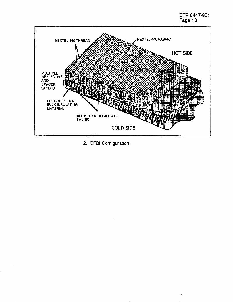
The flexible insulation to be developed and optimized in this test program is aComposite Flexible Blanket Insulation (CFBI) developed at the NASA Ames ResearchCenter. The CFBI is multilayer insulation consisting of ceramic fabrics, insulation, andreflective foils that are separated by ceramic scrim cloths and is of similar constructionto the AFRSI used in the Shuttle Thermal Protection System except for the reflectivefoils and scrim cloths. CFBI insulation is intended for use in the space vacuum whengas conductivity between the foils is negligible and the overall effective thermalconductivity is very small. The foils are used to reflect any radiative component in theSSTO heating environment. This appropriately designed CFBI insulation couldoperate efficiently within the heating and pressure environment of SSTO, providing aweight savings compared to other types of insulation. This task will develop the blanketradiation shield composite with an emphasis on operations issues as well asperformance. Integration of multi layer insulation (MLI) into the TABI flexible blanket isa task goal. All materials will be selected and evaluated with respect to missionenvironment effects on optical properties. Performance will be evaluated, installationprocess variables will be investigated. Overall thermal performance will bedemonstrated using arc-jet for high temperature testing and liquid nitrogen boil-off forcryogenic testing. Demonstration of mission performance will then be accomplishedincluding such tests as radiant heat, arc jet, vibro-acoustic and temperature/pressurecycling.
3.0 APPLICABLE DOCUMENTS:
Co-operative Agreement: NCC2 - 9003 "Lightweight DurableThermal Protection System"
DTP 6447-801
Page 4
4.0 GENERAL REQUIREMENTS:
4.1 Documentation
1. Detailed Test Procedure (DTP) All testing will be conducted inaccordance with these test procedures.
2. Laboratory_ Notebook A Laboratory Notebook will be maintained by theRockwell Responsible Test Engineer (RTE) depicting a complete test history.Test article configuration, instrumentation, test anomalies and all otherpertinent data and information will be recorded.
3. Test Report The test agency will issue a Laboratory Test Report (LTR). Thetest report will depict the complete test program, instrumentation, testprocedures and results, test setup, photographs, test data and any otherpertinent information.
4.2 Test Facility
Test equipment and facilities will be utilized at both government and industry facilities.Appropriate facilities are selected to best simulate the identified SSTO flightenvironments. Test facilities which will be used are listed below.
• NASA-Ames arcjet facilities, 60 and 20 MW facilities• NASA-Ames light gas gun• Rockwell cryogenic tank facility for ice/frost testing• Rockwell rain/wind facility• Rockwell salt spray environment facility• Rockwell vibroacoustic facility• Rockwell radiant heat facility
Schedules and test requirements are defined in Section 2 Sub Tasks Description, ofthis document. Detailed test procedures are located in the Appendix, Section 3.
4.3 Instrumentation:
All measurement instrumentation shall be calibrated and have a decal showing a validcalibration date. A list of all test instrumentation will be maintained in a LaboratoryNotebook.
4.4 Test Conduct:
The test program will be conducted under the direction of the task leader or adesignated representative.
SECTION: 2
DTP 6447-801Page 5
SUB TASKS DESCRIPTIONS
2.2. RADIATION SHIELD DEVELOPMENT:
2.2.1. INTRODUCTION:
MLI (radiation shield) development - This task will include the selection and definitionof radiation shield materials and development of assembly techniques for the packageattachment to the adjacent blanket. Metallic foils and metalized organic films will beassessed for optical properties, and handling/assembly characteristics. Selectioncriteria will include the effect of critical mission environments (salt fog, humidity,waterproofing) on radiation shield optical properties.
2.2.2. OBJECTIVE:
Evaluate and define materials characterization as applicable to assembly processingand performance characteristics. Candidate materials will be assessed through thetest methods defined below to evaluate handling/processing and typical environmentaleffects on the performance of the radiation shield materials.
2.2.3. APPLICABLE DOCUMENTS:
ASTM B 117 Salt Spray (Fog) Testing
ASTM E 408 Total Normal Emittance of Surface UsingInspection Meter Techniques
ASTM E 490 Solar Constant and Air Mass Zero SolarSpectral Irradiance Tables
MIL-STD - 810 D Environmental Tests Methods and EngineeringGuidelines
MLO311-0010 Fabrication of Multilayer Insulation Blankets
2.2.4. REQUIREMENTS:
1. Baseline assembly of the radiation shield package shall comply with ML0311-0010.Deviations will be documented as applicable to the SSTO program.
2.2.5. TEST ARTICLE DESCRIPTION:
DTP 6447-801Page 6
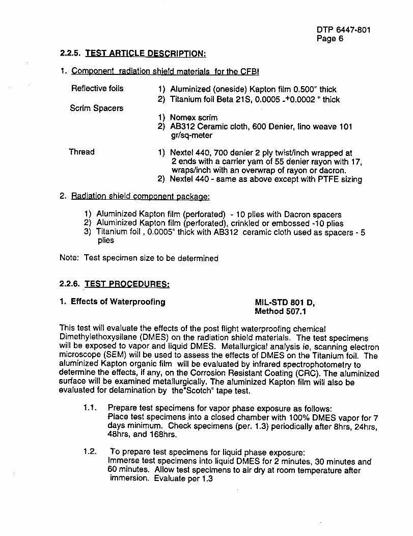
1. Component radiation shield materials for the CFBI
Reflective foils
Scrim Spacers
1) Aluminized (oneside) Kapton film 0.500" thick2) Titanium foil Beta 21S, 0.0005 -+0.0002 "thick
1) Nomex scrim2) AB312 Ceramic cloth, 600 Denier, lino weave 101
gr/sq-meter
Thread 1) Nextel 440, 700 denier 2 ply twist/inch wrapped at2 ends with a carrier yam of 55 denier rayon with 17,wraps/inch with an overwrap of rayon or dacron.
2) Nextel 440 - same as above except with PTFE sizing
2. Radiation shield component package:
1) Aluminized Kapton film (perforated) - 10 plies with Dacron spacers2) Aluminized Kapton film (perforated), crinkled or embossed -10 plies3) Titanium foil, 0.0005" thick with AB312 ceramic cloth used as spacers - 5
plies
Note: Test specimen size to be determined
2.2.6. TEST PROCEDURES:
1. Effects of Waterproofing MIL-STD 801 D,Method 507.1
This test will evaluate the effects of the post flight waterproofing chemicalDimethylethoxysilane (DMES) on the radiation shield materials. The test specimenswill be exposed to vapor and liquid DMES. Metallurgical analysis ie, scanning electronmicroscope (SEM) will be used to assess the effects of DMES on the Titanium foil. The
aluminized Kapton organic film will be evaluated by infrared spectrophotometry todetermine the effects, if any, on the Corrosion Resistant Coating (CRC). The aluminizedsurface will be examined metallurgically. The aluminized Kapton film will also beevaluated for delamination by the"Scotch" tape test.
1.1° Prepare test specimens for vapor phase exposure as follows:Place test specimens into a closed chamber with 100% DMES vapor for 7days minimum. Check specimens (per. 1.3) periodically after 8hrs, 24hrs,48hrs, and 168hrs.
1.2. To prepare test specimens for liquid phase exposure:Immerse test specimens into liquid DMES for 2 minutes, 30 minutes and60 minutes. Allow test specimens to air dry at room temperature afterimmersion. Evaluate per 1.3
1.3.
DTP 6447-801
Page 7
Perform metallurgical analysis on the titanium foil to check for evidence ofcorrosion. Perform infrared spectrophotometric analysis or equivalent onthe aluminized Kapton, and check for evidence of degradation. Check fordelamination by the "Scotch" tape test.
2. Salt Fog Salt Fog - ASTM B 117
3. Humidity MIL-STD-810 D, Method507.1, Procedure I
Each radiation shield package will be placed into a humidity chamber and submitted toa minimum of 10 humidity cycles. Each cycle is 24 Hrs. beginning at room temperatureand increasing to 150OF and back to room temperature while maintaining R.H. inexcess of 95%.
4. Optical Properties
This test is designed to evaluate the effects of typical operations vehicle environmentson the optical properties of the radiation shield package. The test specimens will havebeen exposed to the post flight waterproofing chemical, DMES, and salt fog andhumidity representative of launch pad conditions. The test specimens will have beenprepared in tests 1. through 3. of this sub task. A control specimen will be used toestablish a point of reference.
A. Emittance ASTM E 408, Method A
Gier-Dunkle, DB100 infrared reflectometer
1. Perform normal emittance testing at room temperature.2. The test equipment shall be calibrated with a certified standard supplied by Gier-
Dunkle.
3. The emittance wavelength shall be detected through a potassium bromide window.The wavelength range is 5-25 microns.
B. Absorptivity Testing ASTM E 490 -73a
Beckman, DK-2A UV-VIS-NIR Spectrophotometer
1. Perform solar absorptance testing using a dual beam, ratio recordingspectrophotometer with the beam light incident at 5 degrees from normal. Thereflected light is scattered into a 6 inch diameter integrating sphere and detected byeither a lead sulfide cell or a photomultiplier tube.
2. Record reflectance data as a percentage of a working standard's reflectance.Calibrate working standard against an NBS specular standard.
3. Record data from 280 to 2500 nanometers.
DTP 6447-801Page 8
4. Compute Solar absorptance (Alpha) based on 25 equal energy intervals centeredon wavelengths from 215 nanometers to 2600 nanometers. These wavelengths arecomputed from spectra tables in ASTM E 490.
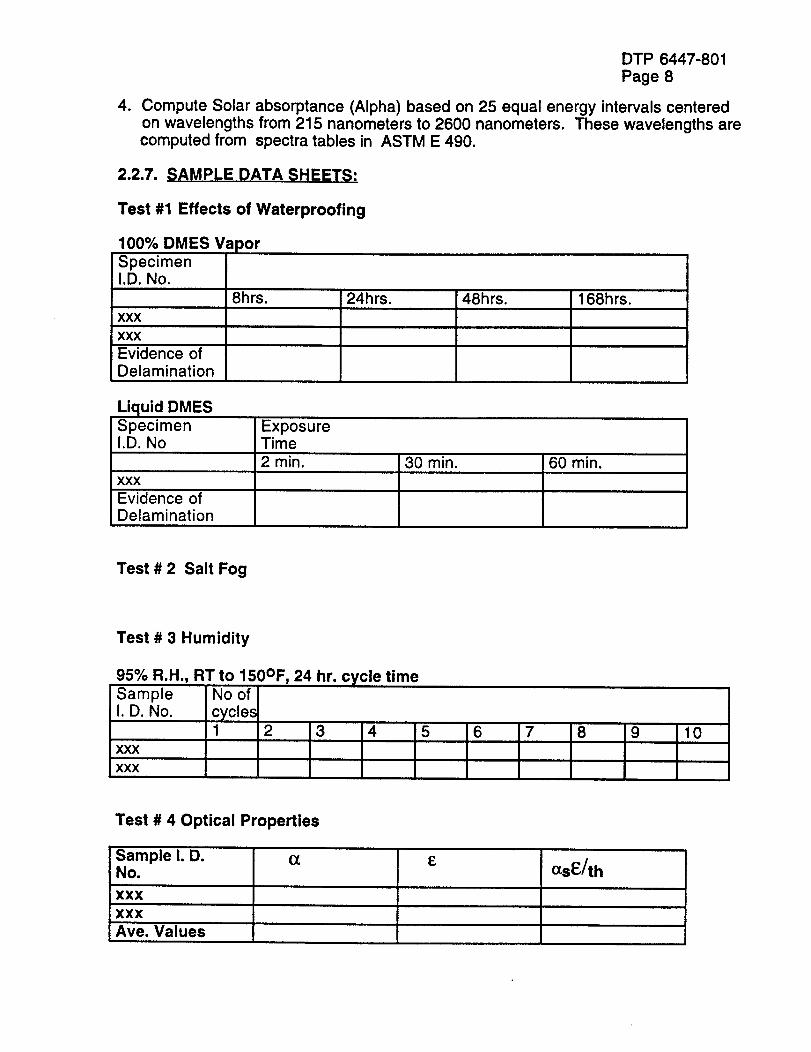
2.2.7. SAMPLE DATA SHEETS:
Test #1 Effects of Waterproofing
100% DMES Va )or
SpecimenI.D. No.
8hrs.XXX
XXX
Evidence ofDelamination
24hrs. 48hrs. 168hrs.
Liquid DMESSpecimen ExposureI.D. No Time
2 rain. 30 min. 60 min.xxxEvidence ofDelamination
Test # 2 Salt Fog
Test # 3 Humidity
95% R.H., RT to 150OF, 24 hr. cycle timeSample No ofI. D. No. cycle_
1 2 3 4XXX
XXX
5 6 7 8 9 10
Test # 4 Optical Properties
_-'oamp,eI.D. o_ ENo. ccsE/th
XXX
XXX
Ave. Values
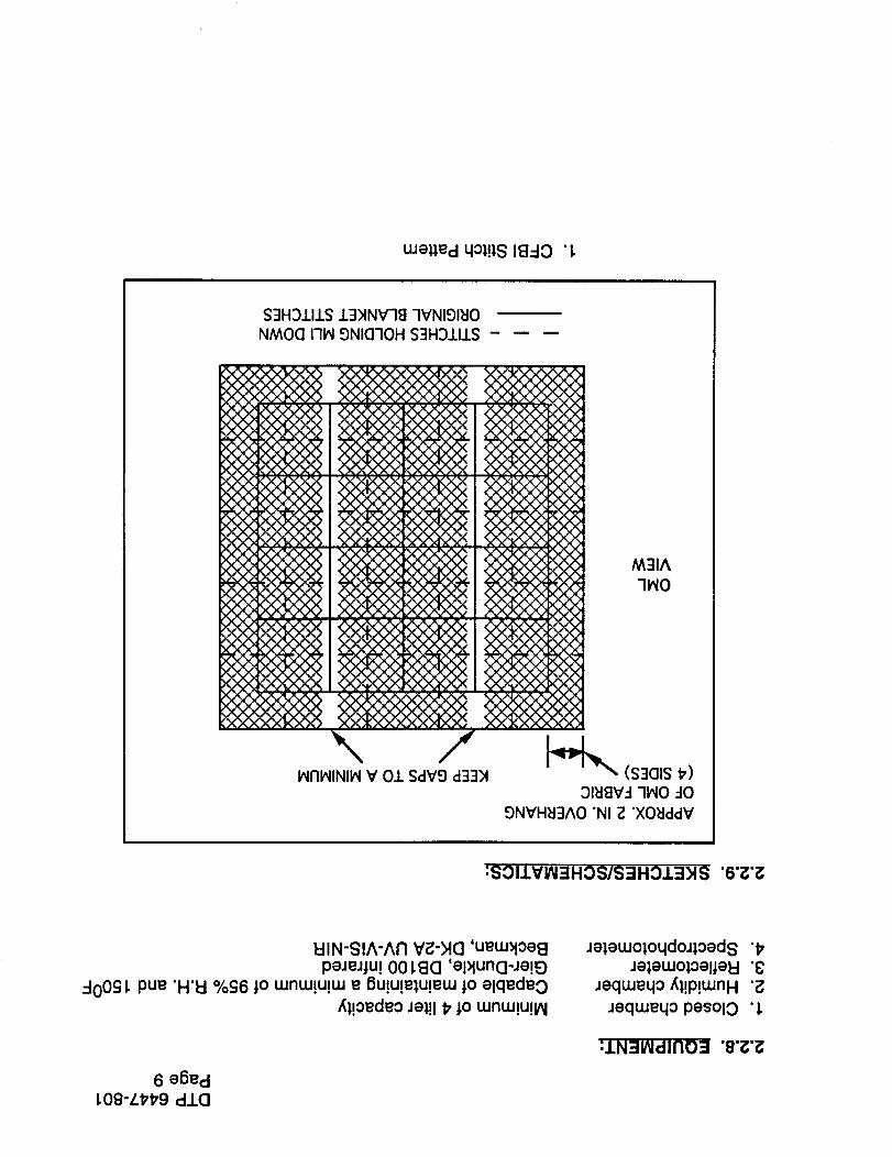
uJe_ed 4o;!18 18..-IO 'i.
$3H3/I.1.S .L3)INV78 -IVNI91_ONMOQ Iql_ 9NI(3"1OH S3H:DJ.I.LS
\1_I71_INII_V 01 SdV9 d33N
:SOIIVIN=IHOS/S::IHOJ.=;HS "6"_'_
I::IIN-SIA-AI7 V;3-HC] 'uew>lOe8peJeJtu! 001.8G 'epluncI-Je!_D
..-100£I. pue "H'ld %cj6:1.o wnuJ!u!uJ e 8u!u!elu!ew j.o elqedeo/_;!oedeo Jel!l P t0 wnw!u!p/
6 e6ed
i.08-L#'#'9 alo
Je;ewo;o4doJ_,oed 8 "#
Je;ewol.oeueld "8Jeqwe4o/_;!p!wnH "_
Jeqwe4o pesolO "1.
:IN=IlNdlFIO =l "8"g'_
DTP 6447-801
Page 10
NEXTEL 440 THREAD NEXTEL 440 FABRIC
HOT SIDE
MULTIPLEREFLECTIVEANDSPACERLAYERS
FELT OR OTHERBULK INSULATINGMATERIAL
ALUMINOBOROSILICATEFABRIC
COLD SIDE
2. CFBI Configuration
2.2.10. SCHEDULE FOR SUB TASK:
*Definition/Selection of radiation shield
MLI package and a purchase order prepared
Begin test specimen preparation/for exposure towaterproofing, salt fog & humidity environments
*Testing of MLI optical properties initiated
*Measure optical properties afterenvironmental exposure
* Denotes milestones
DTP 6447-801
Page 11
August 30, 1994
September 30, 1994
October 15, 1994
April 30, 1995
DTP 6447-801Page 12
2.3 DEVELOPEMNT/CHARAC:TERIZATION OF BLANKET RADIATIONSHIELD COMPOSITE
2.3.1. INTRODUCTION:
The development of process/assembly procedures for the blanket-MLI composite willinclude determining size limitations, edge close-outs, installation over contouredsurfaces, weight and uniformity. The effect of process variables on performance will bedetermined by radiant heat, air impingement, venting, salt spray/arc jet (corrosion) andvibroacoustic tests. Initial development may be performed with CFBI but the ultimategoal is to combine the MLI package with advanced flexible TPS (TABI).
2.3.2. OBJECTIVES:
Develop an attachment process for MLI, which when installed onto flexible insulationwill form an efficient high-temperature flexible blanket composite. Attachmenttechniques developed on CFBI will be applicable to TABI. Attachment/assemblyprocesses will be evaluated in the Composite Flexible Blanket Insulation (CFBI)configuration by defining the blanket's performance limits when subjected to thefollowing tests defined in 2.3.6..
2.3.3. APPLICABLE DOCUMENTS:
MA0606-317 RTV Adhesive Bonded FlexibleInsulation
ML0311-0010 Fabrication of Multilayer InsulationBlankets
MB0135-012 Insulation, Thermal, Fibrous
MB0135-089 Fabric, Glass, High Temperature
MB0135-102 Thread, High Temperature Ceramic
MB0135-079 Aluminized Polyimide Film
2.3.4. REQUIREMENTS:
1. Baseline processing for CFBI test specimens will be per MA0606-317, except asnoted.
2. Baseline processing for the radiation shield package will be per ML0311-0010,except as noted.
DTP 6447-801Page 13
2.3.5. TEST ARTICLE DE$_:RIPTION:
Materials1. Nextel 440 Fabric
Interlock weave, Pat # 5,277,959(figure #4)
SuDDliersFabric Development1217 Mill St.Quakertown, Pa 18951
2. Q-Felt Insulation
61bs/ft.3 density(MB0135-012, Ty I, CI2)
Schuller Speciality Insulation, Div.P.O. Box 5108
Denver, Colorado, 80217-5108
3. AB312 Fabric
(MB0135-089)J.P. Stevens & Co.Slater, S. C.
4. Thread, Nextel 440, 700D/2ply(MB0135-102, Ty II
3M Company225-4N, 3M CenterSt. Paul, Mn. 55144
5. Aluminized Kapton filmOne sided, 0.0002" thick(MB0135-084 ,ty I, cl 1, grade A)
Sheldahl
801 N. Highway 3P.O. Box 170Northfield, Mn.55057
Sufficient blanket materials to produce a minimum of:50 sq. ft of 1" thick standard CFBI
2.3.6. TEST PROCEDURES:
1. Thermal Conductance Testby Radiant Heat
DTP 6451-819, Appendix
Objective:
Establish baseline thermal conductivity data by measuring structure backfacetemperature differential by comparing standard AFRSI with standard CFBI whenexposed to a radiant heat test. Thermal data obtained from this test will be used forcomparison/screening purposes when evaluating the performance characteristics ofthe radiation shield package. Orbiter reentry temperature and pressure profile will beused. NASA Ames will supply one each 8"x8" test specimen.
Test Method:This test will assess the thermal performance characteristics of CFBI in a radiant heatenvironment. Each test specimen shall be exposed to three radiant mission profiles(baseline orbiter) with maximum surface temperatures of 800, 1100 and 1500OF.Figures 1 thru 3 in 2.3.9. define time, temperature and pressure requirements.
2. Salt Spray/Arc Jet DTP 6451-810, Appendix A
DTP 6447-801Page 14
3. Air Jet Impingement DTP 6451-822, Appendix L
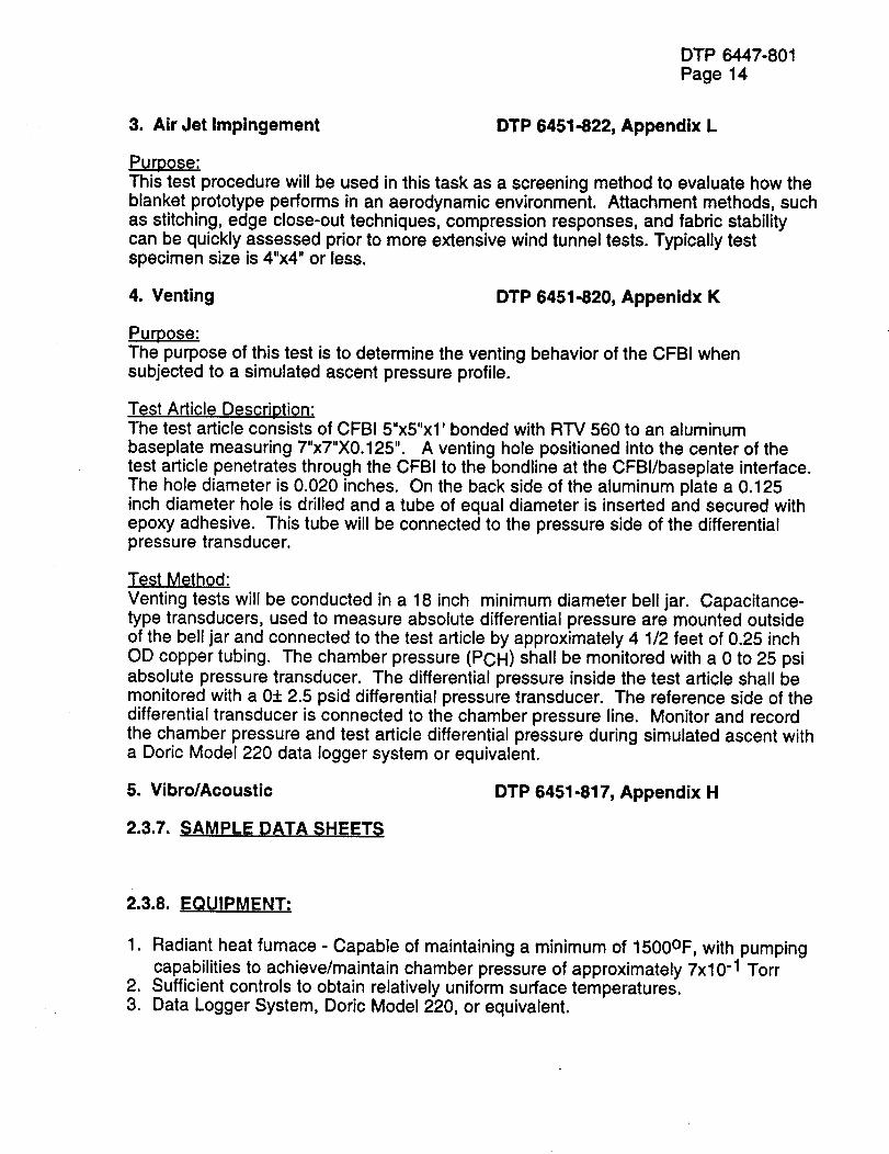
Purpose:This test procedure will be used in this task as a screening method to evaluate how theblanket prototype performs in an aerodynamic environment. Attachment methods, suchas stitching, edge close-out techniques, compression responses, and fabric stabilitycan be quickly assessed prior to more extensive wind tunnel tests. Typically testspecimen size is 4"x4" or less.
4. Venting DTP 6451-820, Appenidx K
Purpose:The purpose of this test is to determine the venting behavior of the CFBI whensubjected to a simulated ascent pressure profile.
Test Article Description:The test article consists of CFBI 5"x5"x1' bonded with RTV 560 to an aluminumbaseplate measuring 7"x7"X0.125". A venting hole positioned into the center of thetest article penetrates through the CFBI to the bondline at the CFBI/baseplate interface.The hole diameter is 0.020 inches. On the back side of the aluminum plate a 0.125inch diameter hole is drilled and a tube of equal diameter is inserted and secured withepoxy adhesive. This tube will be connected to the pressure side of the differentialpressure transducer.
Test Method:
Venting tests will be conducted in a 18 inch minimum diameter bell jar. Capacitance-type transducers, used to measure absolute differential pressure are mounted outsideof the bell jar and connected to the test article by approximately 4 1/2 feet of 0.25 inchOD copper tubing. The chamber pressure (PCH) shall be monitored with a 0 to 25 psiabsolute pressure transducer. The differential pressure inside the test article shall bemonitored with a 0+ 2.5 psid differential pressure transducer. The reference side of thedifferential transducer is connected to the chamber pressure line. Monitor and recordthe chamber pressure and test article differential pressure during simulated ascent witha Doric Model 220 data logger system or equivalent.
5. Vibro/Acoustic DTP 6451-817, Appendix H
2.3.7. SAMPLE DATA SHEETS
2.3.8. EQUIPMENT:
1. Radiant heat fumace- Capable of maintaining a minimum of 1500OF, with pumpingcapabilities to achieve/maintain chamber pressure of approximately 7x10 -1 Torr
2. Sufficient controls to obtain relatively uniform surface temperatures.3. Data Logger System, Doric Model 220, or equivalent.
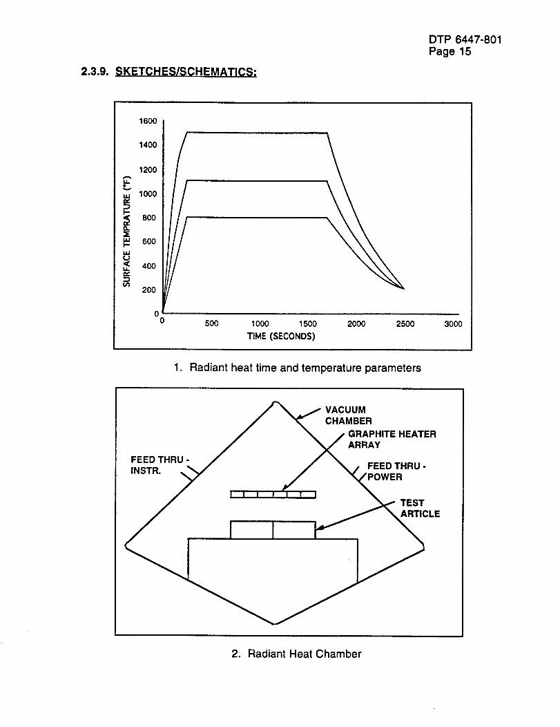
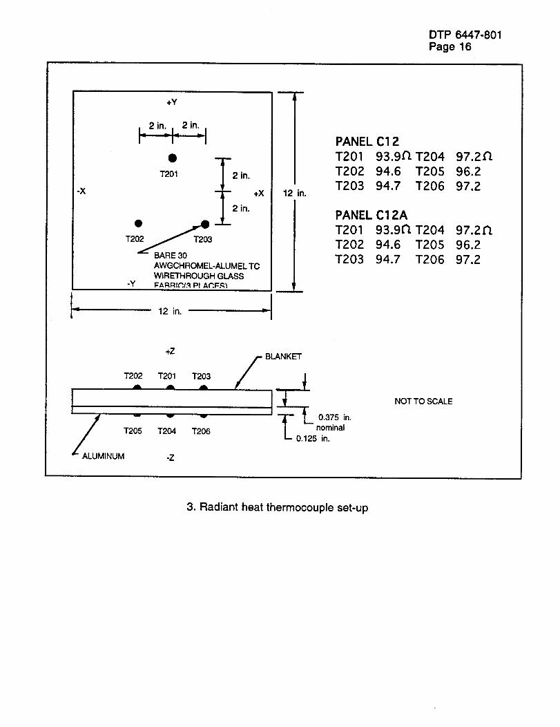
2.3.9. SKETCHES/SCHEMATIG$:
DTP 6447-801Page 15
,800I
1400 I
1200 I
- I/,_ lOOO
_ 800_ 4oo
_ 200
o;-500 1000 1500 2000 2500
TIME (SECONDS)
3000
1. Radiant heat time and temperature parameters
FEED THRU -
INSTR. •
VACUUM
CHAMBER
GRAPHITE HEATERARRAY
FEED THRU -
I I
TEST
ARTICLE
2. Radiant Heat Chamber
DTP 6447-801Page 16
-X
+Y
1201
T2
BARE 30
-y
2 in.
- ÷X
2 in.
n
AWGCHROMEL-ALUMEL TCWIRETHROUGH GLASSFARRI_(R Pl A_,,I=R_
12 in.
12
1
m
II1.
PANEL C12
T201 93.9_T204 97.2_
T202 94.6 T205 96.2
T203 94.7 T206 97.2
PANEL C12A
T201 93.9_ T204 97.2_
T202 94.6 T205 96.2
T203 94.7 T206 97.2
1202A
!
+Z
T201 T203J& ,ill
A_LUM v
T2_5 T204
INUM -Z
BLANKET
T I_ in.nominal0.125 in.
NOT TO SCALE
3. Radiant heat thermocouple set-up
DTP 6447-801Page 17
2.3.10. SCHEDULE FOR SUB TASKS:
*Preliminary plan for assembly of blanketJMLlpackage
*Perform development of MLI assemblyand fabricate insulation blanket components
*Demonstrate attachment of MLI to blanket
*Perform development of blanket/MLl assemblyand edge close-out
*Perform characterization tests on blanket/MLlcomposite specimens
*Denotes Milestones
November 15, 1994
December 23, 1994
December 23, 1994
February 15, 1995
April 30,1995
DTP 6447-801Page 18
2.4. INSTALLATION OF BLANKET/MLI
2.4.1. INTRODUCTION:
Process installation development for the CFBI onto typical SSTO vehicle structureswill include devising attachment techniques, controlling steps and gaps, and providingfor structure transitions, interfaces and penetrations. Baseline AFRSI installationprocessing will be assessed for applicability to CFBI. Alternative installation methods,such as mechanical attachment with the use of Velcro will also be assessed.
Performance evaluation will be by arcjet testing.
2.4.2. OBJECTIVE:
Define installation requirements for CFBI which comply to all SSTO structureconditions and determine the effect of installation variables on blanket performance.
2.4.3. APPLICABLE DOCUMENTS:
1. ML0301-00342. MA0606-3173. ASTM D 903
Flexible Insulation (FI) Installation - Orbiter VehicleRTV Adhesive Bonded Flexible Insulation
Peel or Stripping Strength of Adhesive Bonds, Testfor
2.4.4. REQUIREMENTS:
1. Baseline processing for CFBI shall be in accordance with ML0301-0034. Deviationsas required for the SSTO program will be documented.
2.4.5. TEST ARTICLE DESCRIPTION:
1. Peel test coupons 6" by 9", quantity as required2. 10 instrumented 1" thick standard CFBI3. Planform size to be determined
2.4.6. TEST PROCEDURES:
1. Arc jet DTP 6451-810, Appendix A
2 Peel Test ASTM D 903
The purpose of this is to quickly assess the effects of structure transitions andinterfaces for bonded installations. This test will be used as a screening test and thetest results compared to baseline AFRSI installations.
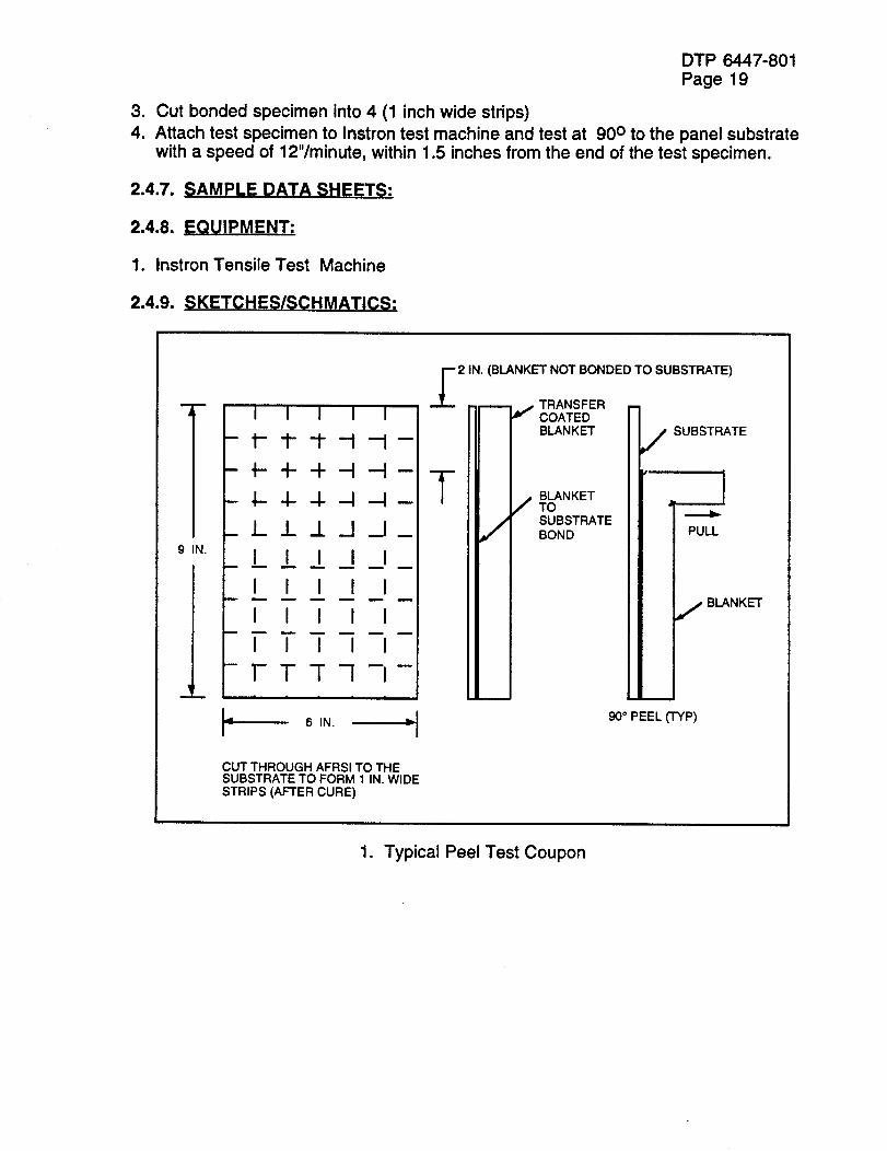
Specimen Preparation - Refer to Sketch #1. "Typical Peel Test Coupon"
1. Bond a six by nine inch CFBI test specimen to an aluminum test panel per MA0-606-317.
2. Verify Shore a minimum of "A "50 for RTV adhesive
DTP 6447-801
Page 19
3. Cut bonded specimen into 4 (1 inch wide strips)
4. Attach test specimen to Instron test machine and test at 90 ° to the panel substratewith a speed of 12"/minute, within 1.5 inches from the end of the test specimen.
2.4.7. SAMPLE DATA SHEETS:
2.4.8. EQUIPMENT:
1. Instron Tensile Test Machine
2.4.9. SKETCHES/SCHMATICS:
i
l
i
9 IN.
I
m m
i
i
m
m
--2 IN. (B_NK_ NOT BONDED TO SUBST_TE)
i TRANSFERI I I I I -- -- _ COATED
_ _ _ _- B_NK_
_ @ _ _ B_NKETTO
TTT -,7TT -iTTT -j
FTT - !
6 IN. d
PUL_
B_NK_
_° PEEL _P)
CUT THROUGH AFRSI TO THESUBSTRATE TO FORM 1 IN. WIDESTRIPS (AFTER CURE)
1. Typical Peel Test Coupon
2.4.10. SCHEDULE FOR SUB TASK
*Evaluate methods of attaching blanket/MLIto structure
*Evaluate blanket assembly installationvariables (steps, gaps, transitions)
*Develop techniques for penetrations inblanket/MLI assembly
*Denotes Program Milestones
DTP 6447-801
Page 20
April 30, 1995
January 1, 1996
February 29, 1996
2.5. OPTIMIZATION OF BLANKET/MLI
DTP 6447-801
Page 21
2.5.1. INTRODUCTION:
Thermal analyses will be performed to determine high temperature and cryogenicapplications for the developed blanket. High temperature performance will bedemonstrated through arc jet testing; cryogenic insulation enhancement will beevaluated by liquid nitrogen boil off test.
2.5.2. OBJECTIVE:
To obtain thermal characterization of the CFBI by creating a one dimensional heattransfer math model to emulate the generic variables such as density, thickness andsurface conditions and to correlate this to data obtained from the experimental tests.This data to be used as design criteria for establishing CFBI thickness and gap sizingrequirements. The AFRSI will be used for control purposes.
2.5.3. APPLICABLE DOCUMENTS:
2.5.4. REQUIREMENTS:
2.5.5. TEST ARTICLE DESCRIPTION:
2.5.6. TEST PROCEDURE:
1. Arc jet
2. Radiant Heat
DTP 6451 - 810, Appendix A
DTP 6451 - 819, Appendix J
2.5.7. SAMPLE DATA SHEETS:
2.5.8. EQUIPMENT:
2.5.9. SKETCHES/SCHEMATICS:
SCHEDULE FOR SUB TASKS:
*Thermal performance of blanketJMLIcomposite specimens initiated
*Preliminary analysis of performance ofblanket/MLI for high temperature and cryogenicapplications accomplished
*Cryogenic testing of blanket/MLI insulationon tank specimen initiated
*Initiate aerothermal performance evaluationof blanket/MLI
DTP 6447-801Page 22
July 30, 1995
August 31, 1995
September 30, 1995
November 30, 1995
*Denotes Program Milestones
DTP 6447-801Page 23
2.6. PERFORMANCE DEMONSTRATION
2.6.1. INTRODUCTION:
Mission performance testing under aerothermal, vibroacoustic, vibration/deflection,buffeting, cold soak and pressure profile conditions will be performed using individualor arrays of blankets. Test conditions will be as defined for an SSTO vehicle or can bethose used for Orbiter TPS evaluation.
2.6.2. OBJECTIVE:
The objective of this task is to demonstrate the technology readiness level of the CFBIThermal Protection System (TPS) by subjecting a system prototype to typical SSTOflight environments and conditions.
2.6.3. APPLICABLE DOCUMENTS:
2.6.4. REQUIREMENTS:
2.6.5. TEST ARTICLE DESCRIPTION:
2.6.6. TEST PROCEDURES:
1. Arc jet DTP 6451-810, Appendix A
2. Wind Tunnel DTP 6451-811, Appendix B
3. Vibroacoustic (progressivewave) DTP 6451-817, Appendix H
4. Mechanical vibration (vibration/deflection) DTP 6451-818, Appendix I
5. Ascent pressure profile (orbitcold soak)
TBD
2.6.7. SAMPLE DATA SHEETS:
2.6.8. EQUIPMENT:
2.6.9. SKETCHES/SCHMATICS:
DTP 6447-801
Page 24
2.6.10. SCHEDULES FOR SUB TASKS:
*Extreme environmental thermal testing ofblanket/MLI defined
*Performance evaluation of blanket/MLIcomposite
*Blanket/MLI properties and performance(aerothermal and wind tunnel after installation)
*Test blanket/MLI assembly (vibroacoustic andvibration/deflection)
*Blanket/MLI specimen cold soak andmission profile testing
*Initiate preparation for final report
*Denotes program milestones
August 31, 1995
January 1, 1996
April 30, 1996
June 30,1996
July 30, 1996
September 30, 1996
DTP 6448-801
PAGE 1
ADVANCED STRUCTURES AND TPS
TECHNOLOGIES
NRA 8-12
TA-3 TASK 4
TPS ATTACHMENT METHODS
TASK LEADER: DAN BELL
DETAILED TEST PLAN - DRAFT JULY 22, 1994
Table of Contents
TA-3 Task 4
TPS ATTACHMENT METHODS
1.0 Objective
2.0 Background2.1 Subtask 1: AETB Fabrication
2.2 Subtask 2: Direct Bond
2.3 Subtask 3: Velcro
2.4 Subtask 4: CMC Cover Attachment
3.0 General Requirements3.1 Documentation
3.1.1 Detailed Test Procedure
3.1.2 Laboratory Notebook
3.1.3 Test Report
3.2 Test Facility3.3 Instrumentation
3.4 Test Conduct
4.0 Subtasks
4.1 Select/Provide AETB
4.1.1 Introduction/Background4.1.2 Applicable Documents
4.1.3 Detailed Requirements
4.1.4 Detailed Test Article/Test Specimen Desc.4.1.5 Fabrication Procedure
4.1.6 Sample Data Sheets
4.1.7 Test Equipment4.1.8 Schedule
4.2 Direct Bond Evaluation
4.2.1 Introduction/Background
4.2.2 Applicable Documents
4.2.3 Direct Bond Detailed Requirements4.2.3.1
4.2.3.2
4.2.3.3
4.2.3.4
4.2.3.5
4.2.3.6
In-Plane Strain (6b)
Substrate Deflection (6c)
System Flatwise Tensile Strength (6d)
Array Structure Deflection (6e)
Array Vibroacoustic Performance (6f)
Effects of Structure Mismatch(6g)
DTP 6448-801PAGE 2
Page 4
Page 4
Page 6
Page 8
Page 11
Page 12
Page 13
Page 15
Page 17
Page 19
Page 20
DTP 6448-801PAGE 3
4.3 Velcro Attachment Process Development
4.3.1 Introduction/Background4.3.2 Applicable Documents
4.3.3 Velcro Detailed Requirements4.3.3.1
4.3.3.2
4.3.3.3
4.3.3.4
4.3.3.5
Evaluate Velcro (6h)
Velcro Attachment (6i)
Velcro Joint Strength (6j)
Velcro Attachment Area (6k)Velcro Environmental Effects (61)
Page 21
Page 22
Page 23Page 24
Page 26
Page 27
4.4 CMC Cover Development
4.4.1 Introduction/Background4.4.2 Applicable Documents
4.4.3 CMC Cover Detailed Requirements4.4.3.1
4.4.3.2
4.4.3.3
4.4.3.4
4.4.3.5
CMC Cover Attachment Process Dev. (6m)
CMC Cover Thermal Evaluation (6n)
CMC Cover Substrate Deflection (60)
CMC Vibroacoustic Performance (6p)
CMC Cover Impact Resistance (6q)
Page 29
Page 30
Page 31
Page 32
Page 34
Page 35
5.0 Sample Data Sheets Page 36
DTP 6448-801PAGE4
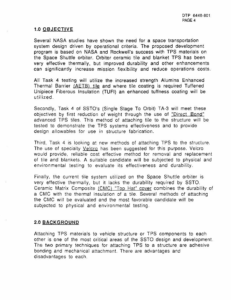
1.0 OBJECTIVE
Several NASA studies have shown the need for a space transportation
system design driven by operational criteria. The proposed development
program is based on NASA and Rockwell's success with TPS materials on
the Space Shuttle orbiter. Orbiter ceramic tile and blanket TPS has been
very effective thermally, but improved durability and other enhancementscan significantly increase mission flexibility and reduce operations costs.
All Task 4 testing will utilize the increased strength Alumina Enhanced
Thermal Barrier (AETB) tile and where tile coating is required Tuffened
Unipiece Fiberous Insulation (TUFI) an enhanced tuffness coating will beutilized.
Secondly, Task 4 of SSTO's (Single Stage To Orbit) TA-3 will meet these
objectives by first reduction of weight through the use of "Direct Bond"
advanced TPS tiles. This method of attaching tile to the structure will be
tested to demonstrate the TPS systems effectiveness and to providedesign allowables for use in structure fabrication.
Third, Task 4 is looking at new methods of attaching TPS to the structure.
The use of specialty VelcrQ has been suggested for this purpose. Velcro
would provide, reliable cost effective method for removal and replacement
of tile and blankets. A suitable candidate will be subjected to physical and
environmental testing to evaluate its effectiveness and durability.
Finally, the current tile system utilized on the Space Shuttle orbiter is
very effective thermally, but it lacks the durability required by SSTO.
Ceramic Matrix Composite (CMC) "Top Hat" cover combines the durability of
a CMC with the thermal insulation of a tile. Several methods of attachingthe CMC will be evaluated and the most favorable candidate will be
subjected to physical and environmental testing.
2.0BACKGROUND
Attaching TPS materials to vehicle structure or TPS components to each
other is one of the most critical areas of the SSTO design and development.
The two primary techniques for attaching TPS to a structure are adhesive
bonding and mechanical attachment. There are advantages and
disadvantages to each.
DTP 6448-801PAGE5
The additional weight, added complexity during original installation andoperational maintenance of fasteners led Rockwell to concentrate onoptimizing the adhesive bond.
Task 4 "TPS Attachment Methods" is separated into the four developmentSubtasks listed below.
Subtask 4.1:AETB-12/AETB-8 FabricationSubtask 4.2: Direct Bond DevelopmentSubtask 4.3: Velcro AttachmentSubtask 4.4: Attachment of "Top Hat" Cover to TPS Tile
A brief introduction to each phase and the test articles developed fromeach follows.
2.1 "Subtask 1: AETB-12/AETB-8 Fabrication". This involves the
fabrication of 12 Ib/ft 3 and 8 Ib/ft 3 Alumina Enhanced Thermal Barrier
(AETB-12/ AETB-8) for use in the final three subtasks of Task 4. Current
specimen requirements call for 157 coated and uncoated tiles ranging in
size from 2-x-2-in coupons to 10-x-10-in tiles. All tiles requiring coating
will be sprayed with Tuffened Unipiece Fiberous Insulation (TUFI).
2.2 "Subtask 2: Direct Bond Development". By direct bonding tile to a
graphite bismalimide (Gr/BMI) structure significant weight savings and/or
thermal performance can realized. The elimination of the strain isolator
pad (SIP) is made possible by the similar coefficient of thermal expansionin the tile and GR/BMI substrate. With the elimination of SIP, substrate
deflections must be limited by design to prevent TPS loss and damage. All
testing in this subtask of Task 4 is based on providing design allowablesfor this structure deflection.
Testing will include in-plane strain, substrate deflection, flatwise tension
on single tile bonded to a graphite bismalimide substrate, deflection,
vibroacoustics, and structure mismatch Testing will be conducted at
room temperature as well as various elevated temperatures.
2.3 "Subtask 3: Velcro Attachment". The use of specialty Velcro has been
suggested for attaching TPS components to vehicle structure or foam.
Velcro could provide benefits in joint reliability, component removal and
weight.
Vendors will be surveyed to find suitable candidate types after which they
will be evaluated to verify their durability to the harsh SSTO flight and
DTP 6448-801PAGE 6
operational environments. Velcro strength/durability will be evaluated on
new material and after several removals. If strength and environmental
durability are adequate, method of attaching the Velcro to the tile,
blankets and various substrates will be explored. On completion of the task
a seven tile array will be fabricated and exposed to humidity, wind/rain,and cold.
2.4 "$ubtask 4: Attachment of "Top Hat" Cover to TPS Tile". Ceramictiles are very efficient and predictable TPS components, but they are
easily damaged by debris and rain/cloud impacts. Flight/operational
restrictions must be placed on a vehicle to protect the current tile
systems from damage. One concept to limit or remove the need for such
restrictions is to increase the "Tuffness" of the tile surface by attaching a
ceramic matrix composite (CMC) to the tile surface. The attached CMC
cover would increase the tile durability yet the system would remain anefficient insulator.
The CMC cover will be attached using adhesive and mechanical methods.Attachment will be conducted on AETB-12 and AETB-8 tile substrates,
first on coupon-size specimens then to 6-x-6-in tiles fabricated forradiant and arc jet thermal tests. CMC cover specimens will then be
attached to GR/BMI substrate and tested for performance under substratedeflection and vibroacoustic loading.
3.0 GENERAL REQUIREMENTS
3.1 Documentation
3.1.1 Detailed Test Procedure (DTP)
All testing will be conducted in accordance with this test procedure.
3.1.2 Laboratory Notebook
A Laboratory Notebook will be maintained by the Rockwell Responsible
Test Engineer (RTE) depicting a complete test history. Test article
configuration, instrumentation, test anomalies and all other pertinent dataand information will be recorded.
DTP 6448-801PAGE7
3.1.3 Test Report
The test agency will issue a Laboratory Test Report (LTR). The test reportwill depict the complete test program, instrumentation, test procedures
and results, test setup, photographs, test data and any other pertinentinformation.
3.2 Test Facility
Test equipment and facilities will be utilized at both government and
industry facilities. Appropriate facilities will be selected to simulate the
interaction of identified adverse environments with specific TPS
components fabricated in Task 4. Test facilities which have beenidentified are listed below.
• NASA-Ames arcjet facilities, 60 and 20 MW facilities
• NASA-Ames light gas gun
• AFWL rain impact facility
• Rockwell International rain/wind facility
• Rockwell International salt fog facility
• Rockwell International vibroacoustic facility
• Rockwell International radiant heat facility
Schedules and test requirements are defined in the detailed test
description section of this document.
3.3 Instrumentation
All measurement instrumentation shall be calibrated and have a decal
showing a valid calibration date. A list of all test instrumentation will be
maintained in a Laboratory Notebook.
3.4 Test conduct
The test program will be conducted under the direction of the task leader
or a designated representative.
DTP 6448-801PAGE8
4.0 SUBTASK DESCRIPTION
4.1 SELECT/PROVIDE AETB-12/AETB-8
4.1.1 Introduction�Background
All Task 4 testing will utilize the increased strength Alumina Enhanced
Thermal Barrier (AETB) tile. Fabrication includes 12 Ib/ft 3 and 8 Ib/ft 3
AETB for use in the final three phases of Task 4. Current specimenrequirements call for 157 coated and uncoated tiles ranging in size from
2-x-2-in coupons to 10-x-10-in tiles. All tiles requiring coating will be
sprayed with Tuffened Unipiece Fiberous Insulation (TUFI).
4.1.2 Applicable Documents
*Production Unit Processing Record-Qualification Series
*TUFI Coating Mix Requirements
*Molybdenum Disilicide Ball Milling
*Silica Hexaboride Ball Milling
*Silica Frit Ball Milling
*Note: Copy of document shown in sample data sheets are found starting onpg 36.
4.1.3 Detailed Requirements
The materials requirements of AETB fabrication are as listed below.
Silica Fiber
Nextel Fiber (AB-312, 3#)
Saffil Fiber (5HA, 3.2#)
Silicon Carbide (320 Grit)
Ammonium Hydroxide (Reagent Grade)
Surfactant (DC-193)
Deionized Water (>1 megohm-cm)
4.1.4 Detailed Test Article/Test Specimen Description
The finished PU shal have the following properties.
Appearance: The specimen shall have no yellow or white spots.
Density: The density shall be between 11.0 and 13.0 Ibs/ft 3.
DTP 6448-801PAGE 9
Tracibility: Each tile shall have impression markings on the side not to be
coated for identification and traceability.
Machining: PU's shall be machined to the specific requirements called out
in subtasks 4.3, 4.4, and 4.5.
4.1.5 Fabrication Procedure
AETB shall be fabricated using the procedures listed in the "Production
Unit Processing Record Qualification Series".
Coating: Coating shall be accomplished using TUFI.
Application: The TUFI shall be applied uniformly in three coats.
°1st Coat: 3g/in2
o2nd Coat: 3g/in2
°3rd Coat: 1.5g/in2
All three coats are applied to the tile surface while, only the first
coat is applied to the tile sidewalls.
4.1.6 Sample Data Sheets
Production Unit Processing Record-Qualification Series
TUFI Coating Mix Requirements
Molybdenum Disilicide Ball Milling
Silica Hexaboride Ball Milling
Silica Frit Ball Milling
4.1.7 Test Equipment
V- Blender, stainless steel, 1 ft 3 min., intensifier bar.
Drying Oven, 350F capability.
DTP 6448-801PAGE 1 0
Casting tower, 8-1/2-x-8-1/2-in and 14-x-14-in with vacuum assist
degassing capability and Hydraulic Ram.
Kiln, 2500F capability
4.1.8 Schedule
Begin AETB-12 fabrication
Fabrication of AETB-12 complete
Begin AETB-8 fabrication
Fabrication of AETB-8 completeInitiate fabrication of 10-x-10-in AETB-12
All fabrication complete
July 11, 1994
August 30,1994
September 1,1994December 23, 1994
December 23,1994
February 15,1995
DTP 6448-801PAGE11
4.2 DIRECT BOND EVALUATION - Evaluate bonding of AETB tiles to
graphite composite substrate without using strain isolator pads (SIP).
Testing will include in-plane strain, deflection, system tensile strength,vibroacoustics and structural mismatch.
4.2.1 Introduction/Backqround
By direct bonding tile to a graphite bismalimide structure significant
weight savings and/or thermal performance can be realized. The
elimination of the strain isolator pad (SIP) is made possible by the similar
coefficient of thermal expansion in the tile and graphite bismalimidesubstrate. With the elimination of SIP, substrate deflections must be
limited by design to prevent TPS loss and damage. All testing in thissubtask provides design allowables for structure deflection as to not
damage the attached TPS.
Testing will include in-plane strain, substrate deflection, flatwise tension
on single tile bonded to a graphite bismalimide substrate, and deflection,
vibroacoustics, and structure mismatch deflection on seven tile arrays.Testing will be conducted at room temperature as well as various elevatedtemperatures.
4.2.2 Applicable Documents
MAO106-319 "RTV Silicon Adhesive-Bonded Silica Reusible Surface
Insulation (RSI) System.
MBO130-119 TYII -RTV 560 Material Specification.
4.2.3 Direct Bond Detailed Requirements
All structure used in the direct bond task will be fabricated usingcomposite graphite/bismalimide. Specimens requiring core will be bondedusing American Cyanimide's HT424 adhesive.
All AETB tile will be bonded to the structure using General Electric's RTV560 silicon adhesive with a nominal bond line thickness of 7-10 mils.
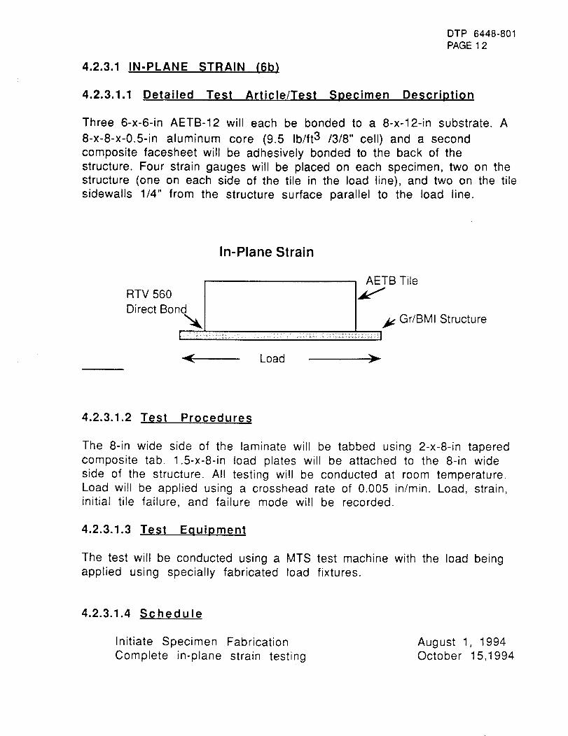
DTP 6448-801
PAGE 1 2
4.2.3.1 IN-PLANE STRAIN (6b)
4.2.3.1.1 Detailed Test Article/Test Specimen Description
Three 6-x-6-in AETB-12 will each be bonded to a 8-x-12-in substrate. A
8-x-8-x-0.5-in aluminum core (9.5 Ib/ft 3 /3/8" cell)and a second
composite facesheet will be adhesively bonded to the back of the
structure. Four strain gauges will be placed on each specimen, two on thestructure (one on each side of the tile in the load line), and two on the tile
sidewalls 1/4" from the structure surface parallel to the load line.
In-Plane Strain
,_B Tile
TVS60\ IDirect Bon
b¢ Gr/BMI Structure
-'4 Load F
4.2.3.1.2 Test Procedures
The 8-in wide side of the laminate will be tabbed using 2-x-8-in tapered
composite tab. 1.5-x-8-in load plates will be attached to the 8-in wide
side of the structure. All testing will be conducted at room temperature.
Load will be applied using a crosshead rate of 0.005 in/min. Load, strain,initial tile failure, and failure mode will be recorded.
4.2.3.1.3 Test Equipment
The test will be conducted using a MTS test machine with the load beingapplied using specially fabricated load fixtures.
4.2.3.1.4 Schedule
Initiate Specimen Fabrication
Complete in-plane strain testing
August 1, 1994October 15,1994
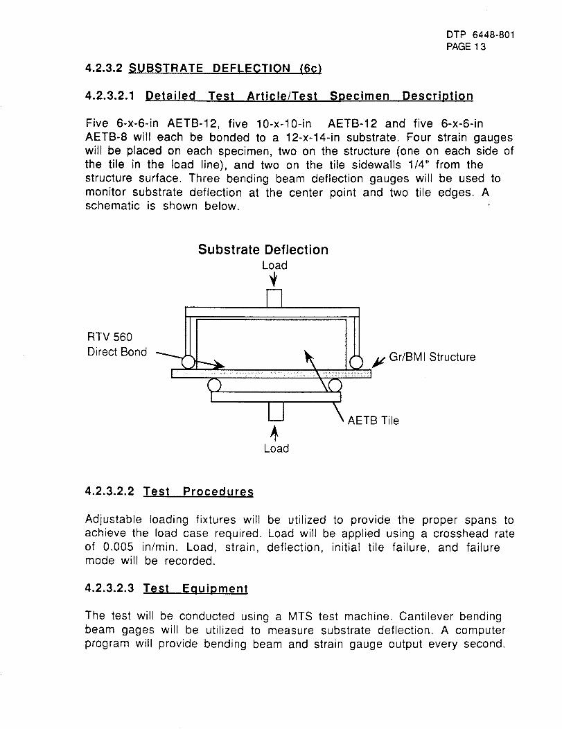
DTP 6448-801PAGE13
4.2.3.2 SUBSTRATE DEFLECTION (6C)
4.2.3.2.1 Detailed Test Article/Test Specimen Description
Five 6-x-6-in AETB-12, five 10-x-10-in AETB-12 and five 6-x-6-in
AETB-8 will each be bonded to a 12-x-14-in substrate. Four strain gauges
will be placed on each specimen, two on the structure (one on each side of
the tile in the load line), and two on the tile sidewalls 1/4" from the
structure surface. Three bending beam deflection gauges will be used to
monitor substrate deflection at the center point and two tile edges. Aschematic is shown below.
RTV 560
Direct Bond
Substrate Deflection
Load
E
_. ......<:::>_._..... _: y Gr/BMI Structure
I
U _ AETB Tile
4Load
4.2.3.2.2 Test Procedures
Adjustable loading fixtures will be utilized to provide the proper spans to
achieve the load case required. Load will be applied using a crosshead rateof 0.005 in/min. Load, strain, deflection, initial tile failure, and failuremode will be recorded.
4.2.3.2.3 Test Equipment
The test will be conducted using a MTS test machine. Cantilever bending
beam gages will be utilized to measure substrate deflection. A computer
program will provide bending beam and strain gauge output every second.
DTP 6448-801PAGE14
4.2.3.2.4 Schedule
Initiate specimen fabricationInitiate fixture fabrication
Single tile deflection testing completeFabrication and test of 10-x-10-in deft.
October 15, 1994
October 15, 1994
December 23,1994
February 15,1995
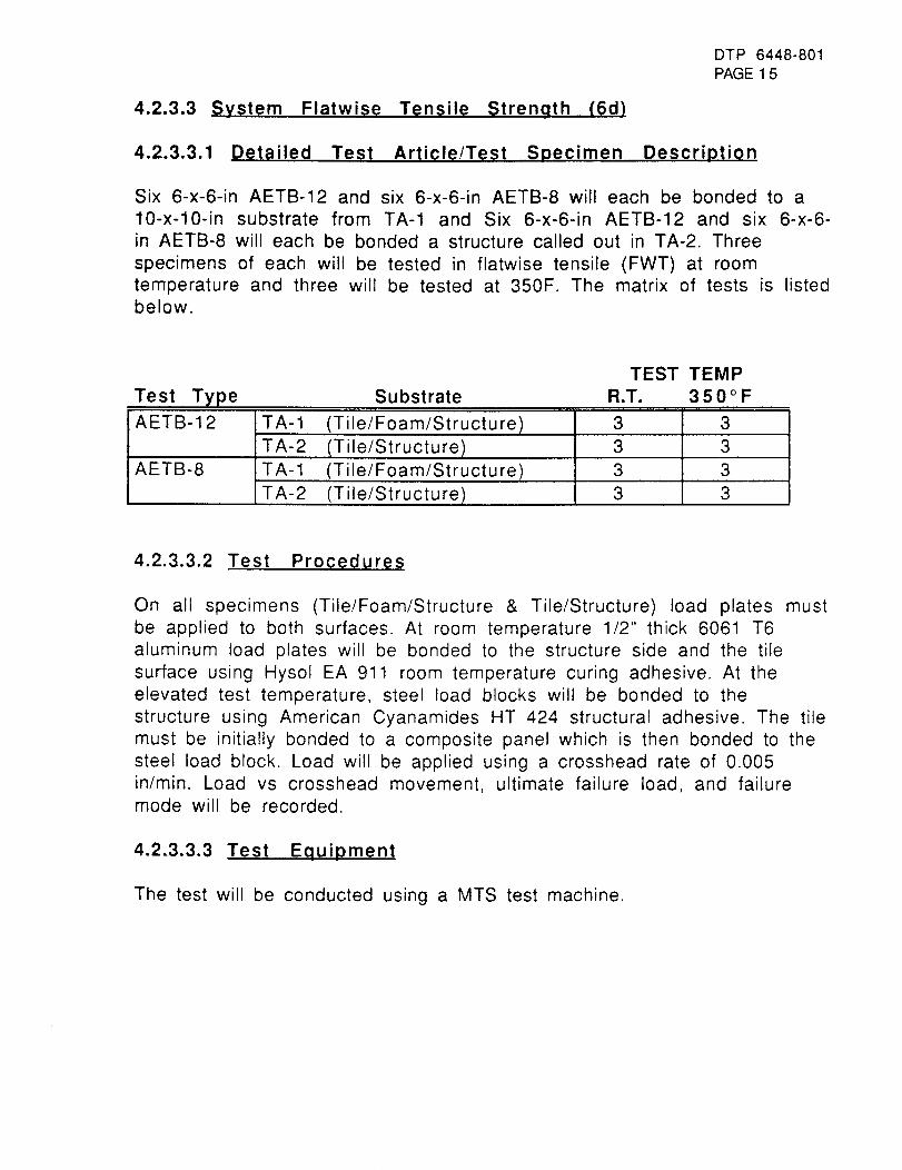
4.2.3.3 System Flatwise Tensile Strength (6d)
DTP 6448-801PAGE 15
4.2.3.3.1 Detailed Test Article/Test Specimen Description
Six 6-x-6-in AETB-12 and six 6-x-6-in AETB-8 will each be bonded to a
10-x-10-in substrate from TA-1 and Six 6-x-6-in AETB-12 and six 6-x-6-
in AETB-8 will each be bonded a structure called out in TA-2. Three
specimens of each will be tested in flatwise tensile (FWT) at room
temperature and three will be tested at 350F. The matrix of tests is listedbelow.
Test Type
TEST TEMP
Substrate R.T. 3 5 0 o F
AETB-12
AETB-8
TA-1
TA-2
TA-1
TA-2
(Tile/Foam/Structu re)
(Tile/Structure)
(Tile/Foam/Structu re)
(Tile/Structu re)
3
3
3
3
3
3
3
3
4.2.3.3.2 Test Procedures
On all specimens (Tile/Foam/Structure & Tile/Structure) load plates must
be applied to both surfaces. At room temperature 1/2" thick 6061 T6
aluminum load plates will be bonded to the structure side and the tile
surface using Hysol EA 911 room temperature curing adhesive. At the
elevated test temperature, steel load blocks will be bonded to the
structure using American Cyanamides HT 424 structural adhesive. The tile
must be initially bonded to a composite panel which is then bonded to the
steel load block. Load will be applied using a crosshead rate of 0.005in/min. Load vs crosshead movement, ultimate failure load, and failure
mode will be recorded.
4.2.3.3.3 Test Equipment
The test will be conducted using a MTS test machine.
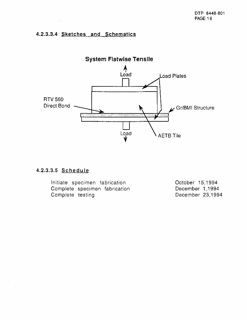
DTP 6448-801PAGE 16
4.2.3.3.4 Sketches and Schematics
RTV 560
Direct Bond
System Flatwise Tensile
L_d Load Plates
IILoad _ AETB Tile
4.2.3.3.5 Schedule
Initiate specimen fabrication
Complete specimen fabrication
Complete testing
October 15,1994
December 1,1994
December 23,1994
DTP 6448-801PAGE 1 7
4.2.3.4 ARRAY STRUCTURE DEFLECTION (6e)
4.2.3.4.1 Detailed Test Article/Test Specimen Description
One 15-x-40-in seven tile array.
4.2.3.4.2 Test Procedures
The panel deflection will be conducted at room temperature, 200F, 300F,
and 400F. The panel will also be subjected to -250F with no deflection
load applied. Tests will be performed first without tiles bonded to the
structure. The substrate array panel with then have AETB-12 direct
bonded, and the deflection tests repeated.
The test panel will be sealed in the "bathtub" fixture as shown in 4.2.3.4.4.
Vacuum will be applied to produce a deflection in the panel. Twenty-threestrain gauges will be bonded to the structure surface. Twelve deflection
gauges will be attached to the panel and subjected as described. Oncompletion of the panel deflection, tile will be bonded to the surface of
the panel in a 4/3 staggered position as shown in 4.2.3.4.4. Additional
deflection gauges will be attached (Approximately 30 total) and the
deflection tests will be repeated.
4.2.3.4.3 Test Equipment
The test will be conducted in the "bathtub" fixture developed for the
Rockwell International Space Shuttle orbiter "IR&D Project 202 Orbiter
Subsystem Design Improvements. S/A 20200 Structural WeightReductions".
Instrumentation will consist of Cantilever bending beam gauges and
rosette/uniaxia strain gauges.
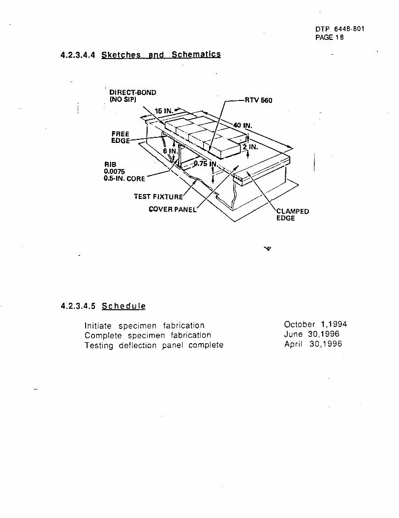
4.2.3.4.4 Sketches and Schematics
DTP 6448-801PAGE 1 8
DI RECT-BOND
(NO SIP) /.-----RTV 560
EDGE i ....."_'-_"l<'--J - - -y
cov,.,,,,,/__/\c.,_,,oEDGE
-,,¢/
4.2.3.4.5 Schedule
Initiate specimen fabrication
Complete specimen fabrication
Testing deflection panel complete
October 1,1994
June 30,1996
April 30,1996
DTP 6448-801PAGE 1 9
4.2.3.5 ARRAY VIBROACOUSTIC PERFORMANCE (6f)
4.2.3.5.1 Detailed Test Article/Test Specimen Description
One 15-x-40-in seven tile array.
4.2.3.5.2 Test Procedures
Accelerometers will be applied to the panel (4.2.3.5.4) and it will be
subjected to vibration and acoustic loading at progressive wave, 160 dB.
The detailed test plan for the vibroacoustics is shown in Appendix H (DTP
6451-817).
4.2.3.5.3 Test Equipment
Test equipment is listed in Appendix H (DTP 6451-817).
4.2.3.5.4 Schedule
Initiate specimen fabrication
Complete specimen fabrication
Vibroacoustic testing, panel complete
October 1,1994
June 30,1996
April 30,1996
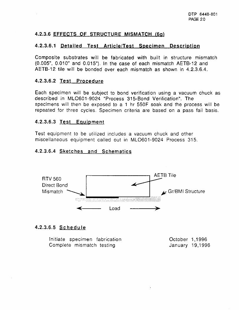
DTP 6448-801PAGE20
4.2.3.6 EFFECTS OF STRUCTURE MISMATCH (6g)
4.2.3.6.1 Detailed Test Article/Test Specimen Description
Composite substrates will be fabricated with built in structure mismatch
(0.005", 0.010" and 0.015"). In the case of each mismatch AETB-12 andAETB-12 tile will be bonded over each mismatch as shown in 4.2.3.6.4.
4.2.3.6.2 Test Procedure
Each specimen will be subject to bond verification using a vacuum chuck asdescribed in MLO601-9024 "Process 315-Bond Verification". The
specimens will then be exposed to a 1 hr 550F soak and the process will be
repeated for three cycles. Specimen criteria are based on a pass fail basis.
4.2.3.6.3 Test Equipment
Test equipment to be utilized includes a vacuum chuck and other
miscellaneous equipment called out in MLO601-9024 Process 315.
4.2.3.6.4 Sketches and Schematics
RTV 60 I t,,eDirect Bond I
Mismatch _[ Gr/BMI Structure:_:__: : i:!ii:ii!iii!::iliiii::ii::ii:ii!iiiiiiiiiiiiiiiiiiiiiiiiiiiiiiiilii
_" Load
4.2.3.6.5 Schedule
Initiate specimen fabrication
Complete mismatch testing
October 1,1996
January 19,1996
DTP 6448-801PAGE21
4.3 VELCRO ATTACHMENT PROCESS DEVELOPMENT
4.3.1 Introduction/Background
The use of specialty Velcro has been suggested for attaching TPS
components to vehicle structure or foam. Suitable candidates will be
evaluated to verify their durability to the SSTO flight and operational
environments. Velcro strength/durability will be evaluated on new
material and after several removals. If strength and environmental
durability are adequate, methods of attaching the Velcro to the tile,
blankets and various substrates will be explored. A seven tile array will
then be fabricated and exposed to humidity, wind/rain, and cold.
4.3.2 Applicable Documents
An Investigation of the Velcro Hi-Garde Metallic Hook and Loop FastenerSystem", NASA Ames Research Center, Angela L. Robinson.
4.3.3 Velcro Detailed Requirements
The Velcro supplied from the vendor shall be evaluated by the tests thatfollow.
DTP 6448-801PAGE22
4.3.3.1 EVALUATE VELCRO (6h}
4.3.3.1.1 Detailed Test Article/Test Specimen Description
4.3.3.1.2 Test Procedure
Testing will include:Material identification/characterization.
Temperature capability.Environmental resistance.
Humidity exposure.
Cryogenic ExposureEase of use.
Removal/installation.
Ability to conform to complex structure.
Attachment to TPS (tiles and blankets).
Strength/durabilityTensile before and after R&R
Peel before and after R&R
4.3.3.1.3 Test Equipment
MTS test machines, thermal and spectrographic equipment, and generallaboratory equipment
4.3.3.1.4 Schedule
"Velcro" vendor search initiated
Velcro evaluation plan complete
Evaluation complete
September 1,1994
November 15, 1994
February 15,1995
DTP 6448-801PAGE23
4.3.3.2 VELCRO ATTACHMENT (6i)
4.3.3.2.1 Detailed Test Article/Test Specimen Description
Five 6-x-6-in tile and five 6-x-6-in blanket coupons will be fabricated
using different methods of adhesive and mechanical attachment. Specimens
will be adhesively bonded using RTV 560 (MBO130-119 TYII) of bondline
thickness from 10 mils to 20 mils and by the use of a structural adhesive
HT 424. For blankets, the adhesive bonding process and sewing the Velcrodirectly to the blanket will be examined.
4.3.3.2.2 Test Procedures
The specimens will be subjected to the 375°F for 1Hr and -160°F for 1Hr.
The specimens will then be subjected to removal and replacement. Visual
inspection will detect any anomalies which be recorded photographically
4.3.3.2.3 Test Equipment
All testing will be conducted using a MTS test machine
4.3.3.2.4 Sketches and Schematics
4.3.3.2.5 Schedule
Initiate Velcro TPS attachment processComplete blanket and tile attachment
February 15,1995June 30, 1995
DTP 6448-801PAGE24
4.3.3.3 VELCRO JOINT STRENGTH (6i)
This task will determine the strength of the Tile/Velcro/Structure system
before and after several removals and re-application have been conducted.
4.3.3.3.1 Detailed Test Article/Test Specimen Description
Twenty 2-x-2-in, eight 6-x-6-in AETB-12 and two12-x-12-in blankets
attached to a composite substrate by the most promising method evaluatedin 4.3.3.1.
4.3.3.3.2 Test Procedure
On all tile specimens load plates will be applied to the structure and tilesurfaces. At room temperature, 1/2" thick 6061 T6 aluminum load plates
will be bonded to the structure side and the tile surface using Hysol EA
911 room temperature curing adhesive. Load will be applied using acrosshead rate of 0.05 in/min. Load vs crosshead movement, ultimate
failure load, and failure mode will be recorded.
Blanket specimens shall be bonded to the structure and 1" strips shall be
cut in from the surface of the blanket through to the structure. The 1" wideblanket strips shall be tested in peel per ASTM D 903.
4.3.3.3.3 Test Equipment
The test will be conducted using a MTS test machine.
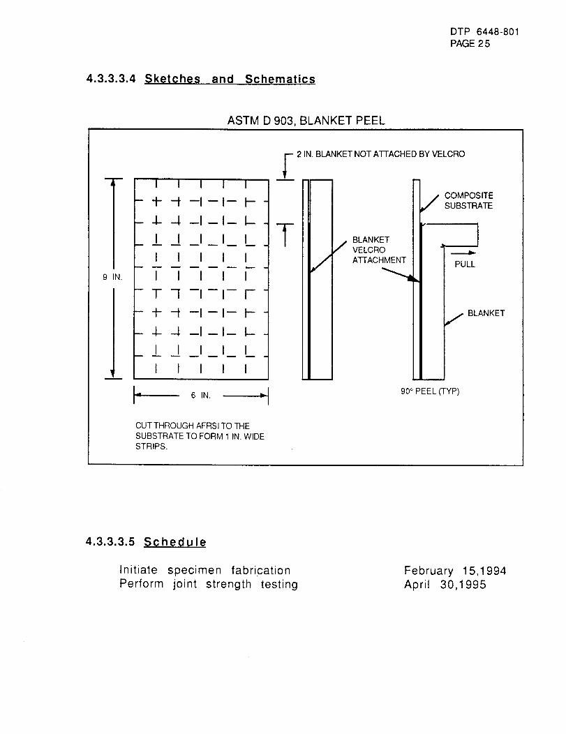
DTP 6448-801PAGE 2 5
4.3.3.3.4 Sketches and Schematics
ASTM D 903, BLANKET PEEL
m
A
9 IN.
I
.f-
4-
I I
I
--I-
--I-
I
I I I
I I
-f--I--
-._ u m
I I
T-[
4--4
I I
I
-I-
-I-
-I-
I
I I I
I
6 IN. _J
CUTTHROUGHAFRSITO THESUBSTRATETO FORM 1 IN. WIDESTRIPS.
,'- 2 IN. BLANKETNOTA'IEACHED BY VELCRO=
!i
T
/BLANKET
J VELCROATTACHMENT
COMPOSITESUBSTRATE
I PULLII
I
,,, BLANKETI
I
I
I
9O° PEEL (TYP)
4.3.3.3.5 Schedule
Initiate specimen fabricationPerform joint strength testing
February 15,1994April 30,1995
DTP 6448-801PAGE 2 6
4.3.3.4 VELCRO ATTACHMENT AREA (6k)
This task will determine the attachment area required (tile/substrate) forattaching tile to the structure below. Also examined will be the
vibroacoustic resilience and venting properties of a 24-x-24-in blanket
attached to the structure using Velcro.
4.3.3.4.1 Detailed Test Article/Test Specimen Description
Five 6-x-6-in AETB-12 bonded using only a 5-x-5-in Velcro footprint, five6-x-6-in AETB-12 bonded using 6-x-6-in Velcro footprint (full footprint)
for use in flatwise tensile testing.
One 24-x-24-in blanket attached to an aluminum substrate using 24-x-24-
in Velcro for use in vibroacoustic and venting tests.
4.3.3.4.2 Test Procedures
On all tile specimens load plates will be applied to the structure and tile
surfaces. At room temperature, 1/2" thick 6061 T6 aluminum load plates
will be bonded to the structure side and the tile surface using Hysol EA
911 room temperature curing adhesive. Load will be applied using acrosshead rate of 0.05 in/min. Load vs crosshead movement, ultimatefailure load, and failure mode will be recorded.
The blanket specimen will subjected to ascent/descent pressure profiles
and examined for disbonds or any other anomalies. The blanket will then be
subjected to vibroacoustics and venting as described in procedures listed
in Appendix H (DTP 6451-817) and Appendix K (DTP 6451-820).
4.3.3.4.3 Test Equipment
Tensile tests will be conducted using a MTS test machine.Venting requirements will be achieved in a environmental chamber.
Vibroacoustic loads will be applied using the equipment listed in
Appendix H (DTP 6451-817)
4.3.3.4.4 Schedule
Initiate fabrication of test specimens
Perform joint strength testFebruary 15,1995April 30, 1995
DTP 6448-801PAGE27
4.3.3.5 VELCRO ENVIRONMENTAL EFFECTS (61)
This task will determine the effects of humidity, wind/rain, salt spray and
cryogenic exposure on Velcro attached tile and blankets. Analysis for GO2
and GH2 at the Velcro joint will be conducted to evaluate safety concerns.
4.3.3.5.1 Detailed Test Article/Test Specimen Description
Five 3-x-3-in AETB-12 tile coupons and five 6-x-6-in AFRSI blanket
coupons.
One 15-x-40-in seven tile array and one 24-x-24-in blanket array.
4.3.3.5.2 Test Procedure
Expose five tile and three blanket coupons to the following conditions,Humidity exposure, 80% R.H. 100°F for 120 hours.
Wind/Rain exposure will be conducted as is described in Appendix F
(DTP 6451-81 5).
Salt spray exposure, 7 day exposure as is described in ASTM Bl17
Cryogenic exposure, The coupons will be exposed to -150°F for 1
hour. This cycle will be repeated 10 times.
Flatwise tensile testing shall be conducted on all coupons and unexposed
controls at room temperature and 0.05 in/min crosshead rate.
The two arrays (blanket and tile) will be subjected to launch pad
conditions. Arrangements will be made with KSC to allow placement of the
panels near the launch pad for a 60 day exposure. Visual inspection and
photographic documentation will be recorded. Bond verification wilt be
conducted per MLO601-924 "Process Bond Verification of RSl Tiles".
One tile and one blanket will be fitted with a capillary sampling tube
embedded in the Velcro. The backface structure temperature will be cooled
using LN2. The Velcro interface will be monitored for any deviation from
the normal concentration of GO2 and GH2 using multiple gas analyzers.
4.3.3.5.3 Test Equipment
Tensile tests will be conducted using a MTS test machine.
Humidity exposures will be conducted in a suitable chamber with controls
capable of maintaining +3 °F and +5% R.H. A chart shall be maintained
documenting the actual temperature and humidity.
DTP 6448-801PAGE28
Wind/Rain exposures will be applied using the equipment listed inAppendix F.Salt Spray exposure shall be conducted in a standard salt spray chamber asis listed in ASTM Bl17Cryogenic exposure shall be accomplished using a test chamber fitted witha controlled LN2 source.
4.3.3.5.4 Schedule
Initiate specimen fabrication
Initiate adverse environments testing
Adverse data collection complete
February 15,1995
August 31, 1995
September 30,1995
.... : . _._.'_,. . _-
DTP 6448-801PAGE 2 9
4.4 CMC COVER DEVELOPMENT
CMC tile cover attachment - A method of attachment will be
developed/demonstrated by attaching it to the surface of an AETB-12 tile.Performance will be demonstrated by thermal exposure, deflection,
vibration and impact.
4.4.1 Introduction/Backqround
Attachment of "Top Hat" Cover to TPS Tile". Ceramic tiles are very
efficient and predictable TPS components, but they are easily damaged by
debris and rain/cloud impacts. Flight/operational restrictions must be
placed on a vehicle to protect the current tile systems from damage. One
concept to limit or remove the need for such restrictions is to increase the
"Tuffness" of the tile surface by attaching a ceramic matrix composite
(CMC) to the tile surface. The attached CMC cover would increase the tiledurability yet the system would remain an efficient insulator.
The CMC cover will be attached using mechanical methods. Attachment will
be conducted on AETB-12 and AETB-8 tile substrates, first on coupon-size
specimens then to 6-x-6-in tiles fabricated for radiant and arc jet
thermal tests. CMC cover specimens will then be attached to GR/BMI
substrate and tested for performance under substrate deflection, impact
and vibroacoustic loading.
4.4.2 Applicable Documents
4.4.3 CMC Cover Detailed Requirements
All AETB tile will be bonded to the structure using General Electric's RTV560 silicon adhesive with a nominal bond line thickness of 7-10 mils.
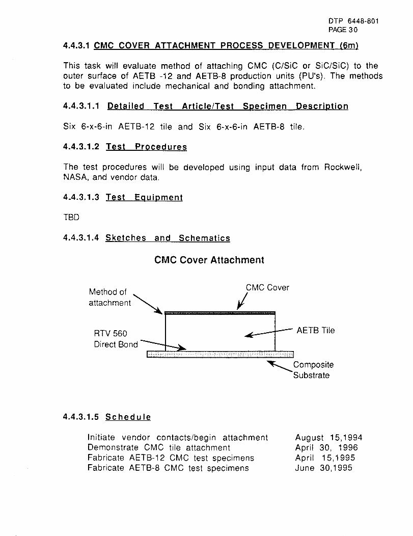
DTP 6448-801PAGE30
4.4.3.1 CMC COVER ATTACHMENT PROCESS DEVELOPMENT (6m)
This task will evaluate method of attaching CMC (C/SiC or SiC/SiC) to the
outer surface of AETB -12 and AETB-8 production units (PU's). The methodsto be evaluated include mechanical and bonding attachment.
4.4.3.1.1 Detailed Test Article/Test Specimen Description
Six 6-x-6-in AETB-12 tile and Six 6-x-6-in AETB-8 tile.
4.4.3.1.2 Test Procedures
The test procedures will be developed using input data from Rockwell,NASA, and vendor data
4.4.3.1.3 Test
TBD
4.4.3.1.4 Sketches
Equipment
and Schematics
CMC Cover Attachment
Method of CMC Cover
attachment"_ . .. / .
RTV 560 i_Direct Bond
::::::::::::::::::::::::::::::::::::::.:: : ::: :i.:.:: :::.:: .:i::::::i..i.i.:i!::::: ::i::::!:i :::: .i ::::::i:ii!:i :!ii::!i::::::i:ii:i.:::ii:iii!:i:i:
Composite_"_Substrate
AETB Tile
4.4.3.1.5 Schedule
Initiate vendor contacts/begin attachmentDemonstrate CMC tile attachment
Fabricate AETB-12 CMC test specimens
Fabricate AETB-8 CMC test specimens
August 15,1994
April 30, 1996
April 15,1995June 30,1995
DTP 6448-801PAGE31
4.4.3.2 CMC COVER THERMAL EVALUATION (6n)
This task will evaluate the performance of CMC/tile composite and its
attachment method to radiant and arcjet thermal exposures.
4.4.3.2.1 Detailed Test Article/Test Specimen Description
one 1-x-6-x-6-in AETB-12 tile and one 1-x-6-x-6-in AETB-8 tile.
4.4.3.2.2 Test Procedures
Each specimen will be subjected to radiant exposures of 1500°F, 2000°F,
and 2500°F using the method described in Appendix J (DTP 6451-819).
Each specimen will be tested using arcjet by the method described in
Appendix A (DTP 6451-810)
4.4.3.2.3 Test Equipment
The test equipment utilized in radiant and arcjet testing is called out in
Appendix J and Appendix A respectively.
4.4.3.2.4 Schedule
Initiate preparation of CMC test specimens October 1,1995
Initiate testing of CMC specimens June 30,1996
DTP 6448-801PAGE32
4.4.3.3 CMC COVER SUBSTRATE DEFLECTION (6o)
AETB-12 tile with attached CMC cover will be direct bonded using 0.090"
thick strain isolator pad. The composite substrate will be subjecteddeflection loads until tile failure occurs.
4.4.3.3.1 Detailed Test Article/Test Specimen Description
Two 6-x-6-in AETB-12. One direct bonded to a composite substrate, one
bonded to the substrate using 0.090" thick strain isolation pad. Four strain
gauges will be placed on each specimen, two on the structure (one on each
side of the tile in the load line), and two on the tile sidewalls 1/4" from
the structure surface. Three bending beam deflection gauges will be used
to monitor substrate deflection at the center point and tile two tile edges.A schematic is shown below.
4.4.3.3.2 Test Procedure
Adjustable loading fixtures will be utilized to provide the proper spans to
achieve the load case required. Load wilt be applied using a crosshead rateof 0.005 in/min. Load, strain, deflection, initial tile failure, and failuremode will be recorded.
4.4.3.3.3 Test Equipment
The test will be conducted using a MTS test machine. Cantilever bending
beam gages will be utilized to measure substrate deflection. A computer
program will provide bending beam and strain gauge output every second.
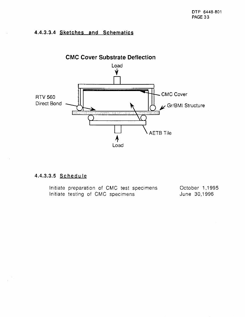
DTP 6448-801PAGE 3 3
4.4.3.3.4 Sketches and Schematics
RTV 560
Direct Bond
CMC Cover Substrate Deflection
Load
m
it
4Load
4.4.3.3.5 Schedule
Initiate preparation of CMC test specimens
Initiate testing of CMC specimens
October 1,1995
June 30,1996
DTP 6448-801PAGE34
4.4.3.4 CMC VIBROACOUSTIC PERFORMANCE (6p}
A seven tile array fabricated from CMC covered tiles will be subjected to
vibroacoustic loads, 160 dB progressive wave.
4.4.3.4.1 Detailed Test Article/Test Specimen Description
One 15-x-40-in seven tile array will be fabricated using the mostpromising method of CMC cover attachment. The tile will be direct bonded
to the composite substrate in a 4/3 tile staggered position allowing 0.02"
gaps.
4.4.3.4.2 Test Procedures
Vibroacoustics will be applied and monitored using 160 dB, progressive
wave, as described in Appendix H (DTP 6451-817).
4.4.3.4.3 Test Equipment
The vibroacoustic test will utilize the equipment listed in Appendix H
4.4.3.4.4 Schedule
Initiate preparation of CMC test specimens
Initiate testing of CMC specimens
October 1,1995
June 30,1996
DTP 6448-801PAGE35
4.4.3.5 CMC COVER IMPACT RESISTANCE (6a)
CMC covered tiles will be subjected to rain and debris impact.
4.4.3.5.1 Detailed Test Article/Test Specimen Description
Twenty 6-x-6-in CMC covered tiles will be direct bonded to a1/8"-x-8-x-8-in aluminum substrate.
4.4.3.5.2 Test Procedure_
Ten CMC covered tiles will be subjected to rain impact at WPAFB as
directed in Appendix D (DTP 6451-813).
Ten CMC covered tiles will be subjected to debris impact using the AMES
light gas gun as described in Appendix C (DTP 6451-812).
4.4.3.5.3 Test Equipment
The rain impact and debris impact will utilize the test equipment describe
in Appendix D and Appendix C respectively
4.4.3.5.4 Schedule
Initiate preparation of CMC test specimens
Initiate testing of CMC specimens
October 1,1995
June 30,1996

5.0 Sample Data Sheets
Production Unit Processing Record-Qualification Series
TUFI Coating Mix Requirements
Molybdenum Disilicide Ball Milling
Silica Hexaboride Ball MillingSilica Frit Ball Milling
DTP 6448-801PAGE 3 6
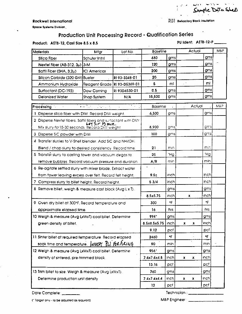
Rockwell International _,]
Space Syslerns Division.
Production Unit Processing Record - Qualification Series
Refractory Block Insulation
Product: AETB-12, Cast Size 8.5 x 8.5 PU Ident:
Materials
Silica Fiber
Nextel Fiber (AB-312.31_)
Saffil Fiber (5HA. 3.214)
Silicon Carbide (320 Grit)
Ammonium Hydroxide
Surfactant (DC- 193)
Mfgr
Schuler Intnl
3-M
ICI Americas
Bueler
Reagent Grade
Dow Coming
Shop System
Lot No.
RI 93-3348-01
RI 93-D5369-01
RI 93D4530-01
N/A
Baseline
680 gins
120 gms
200 gins
20 gins
5 ml
0.5 gins
15,500 gmsDeionized Water
AETB-12-P
Actual M&P
gms
gins
gins
gms
ml
gms
gins
Processing " • ..... Baseline
1 Disperse silica fiber with DIW Record DIW weight. 6,500
2 Disperse Nextel fibers. Saffil fiber;_ and surfoctont witn DIWI-rT" 5,f 13 _,_n.
Mix slurry for15-30 seccnds. Record DI'.V weight
3 Disperse SiC powder with DIW
4
5
6
Transfer slurries to V-Shell blender. Add SiC and NH4OH
Blend / chop slurry to desired consistency Record time.
Transfer slurry to casting tower and vacuum degas tc
remove bubbles Record vacuum pressure and duration.
Re-agitate settled slurry with mixer blade. Extract water
from tower leaving excess over felt. Record felt height.
7 Compress slurry to billet height. Record height.
8 Remove billet, weigh & measure cast block (Avg L x T).
9 Oven dry billet at 300°F. Record temperature and
approximate elapsed time.
10 Weigh & measure (Avg LxWxT) cool billet. Determine
green density of billet.
11 Sinter billet at required temperature. Record elapsed
soak time and temperature. I;,/V_IL_" _.U._,&#iL/&//?
12 Weigh & measure (Avg LxWxT) co01 billet Determine
density of sintered, pre-trimmed block.
13 Trim billet to size. Weigh & measure (Avg _WxT)
Determine production unit density
8,900
100
21
25
A/R
gins
Date Complete:.
(" Target ontv - tO De oCljusted as reau_ted)
Actual M&P
gins
gms
gins
rain
"Hg
min
rain
'Hg
rain
9.5_+ inch inch:
5 314 inch inch
gins gins
8.5x5.75 inch x inch
300 °F °F
16 hrs hrs
994" gms gms
8.Sx8.5x5.75 inch x x inCh
9.12 pcf pcf
2460 °F - °F
90 rain min I -
956" gins gins
7.6x7.6x4.8 inch x x inch
13.16 pcf _cf
760 gins gms
7.4x7.4x4.4 inch x x inch
12 pcf 3cf
Technician '
M&P Engineer •
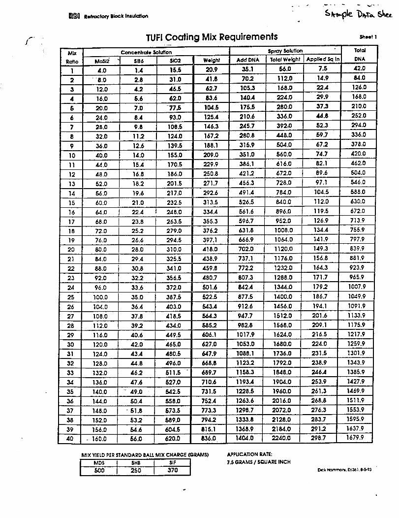
p.,°
!
Mix
Ratio
I
2
3
4
5
6
7
8
9
I0
11
12
13
14
15
16
17
18
19
20
21
22
23
24
25
26
27
28
29
30
31
32
33
34
35
36
37 •
38
39
40
TUFI Coating Mix Re¢
Concentrate Solution
MoSi2" " SlB6 $X32
4.0 1.4 15.5
• "8.0 2.8 31.0
12.0 4.2 46.5
16.0 5.6 62.0
20.0 7.0 -77.5
24.0 8.4 93.0
28.0 9.8 108.5i
124.032.0 11.2
36.0 12.6 139.5
40.0 14.0 155.0
44.0 15.4 170.5
48.0
52.0
16.8
18.2
19.6
21.060.0 I
186.0
201.5
217.0
232.5
uirements
Add DNA
35.1
SpraySolution
Tolal Weight
56.0
70 .2 112.0
105.3 168.0
140.4
175.5
210.6
245.7
I Appl_d Sq In
7.5 42.0
14.9 84.0
22.4 126.0
224.0 29.9
280.0 37.3
336.0 44.8
392.-0 52.3
280.8 448.0 59.7
315.9 504.0 67.2
351.0 560.0 74.7
386.1
421.2
456.3
491.4
526.5
Weight
20.9
41.8
62.7
83.6
104.5
125.4
146.3
167.2
188.1
209.0
229.9
250.8
271.7
292.6
313.5
334.4
355.3
376.2
397.1
418.0
438.9
459.8
480.7
501.6
522.5
543.4
564.3
585.2
606.1
627.0
647.9
668.8
689.7
710.6
731.5
752.4
773.3
794.2
815.1
836.0
64.0 561.6
68.0 596.7
72.0 631.8
76.0
80.0
84.0
88.0
92.0
666.9
702.0
737.1
772.2
807.3
8,42.4
877.5
912.6
947.7
982.8
96.0
I00.0
1_.0
108.0
616.0
672.0
728.0
784.0
8,40.0
896.0
952.0
1008.0
1064.0
1120.0
1176.0
1232.0
1288.0
1344.0
112.0
Sheet 1
DNA
J 89.6
140.0
168.0
210.0
252.0
294.0
336.0
378.0
420.0
82.1 462.0
504.0
22.4 248.0
23.8 263.5
25.2 279.0
26.6 294.5
28.0 J 310.0
29.4 325.5
30.8 341.0
32.2 356.5
33.6 372.0
35.0 387.5
36.4 403.0
37.8 418.5
39.2 434.0
40.6 449.5
42.0 465.0
43.4 480.5
44.8 496.0
46.2 511.5
47.6 527.0
- 49.0 542.5
50.4 558.0
" 51.8 573.5
53.2 589.0
54.6 604.5
56.0 620.0
97.1
104.5
112.0
119.5
126.9
134.4
141.9
149.3
156.8
164.3
171.7
179.2
546.0
588.0
630.0
672.0
713.9
755.9
797.9
839.9
881.9
1400.0 186.7
1456.0 194.1
1512.0 201.6
1568.0 209.1
1624.0 216.5
1680.0 224.0
1736.0 231.5
1792.0 238.9
1848.0 246.4
1904.0 253.9
1960.0 261.3
2016.0 268.8
2072.0 276.3
2128.0 283.7
2184.0 291.2
2240.0 298.7
923.9
965.9
1007.9
1049.9
1091.9
1133.9
1175.9
1217.9116.0 1017.9
120.0 1053.0 1259.9
124.0 1088.1 1301.9
•128.0 1123.2 1343.9
132.0 1158.3 1385.9
136.0 1193.4 1427.9
1228.5 1469.9
BALLMIX CHARGE(GRAMS)
I, 137O
1263.6
1298.7
1333.8
144.0
148.0
152.0
156.0 1368.9
1404.0- 160.0
MIX YIELDPERSTANDARD
i MDS SHB500 250
1511.9
1553.9
1595.9
1637.9
1679.9
APPUCATIONRATE:
7.5GRAMSI SQUAREINCHDick Nommom. D1361,6-5-93
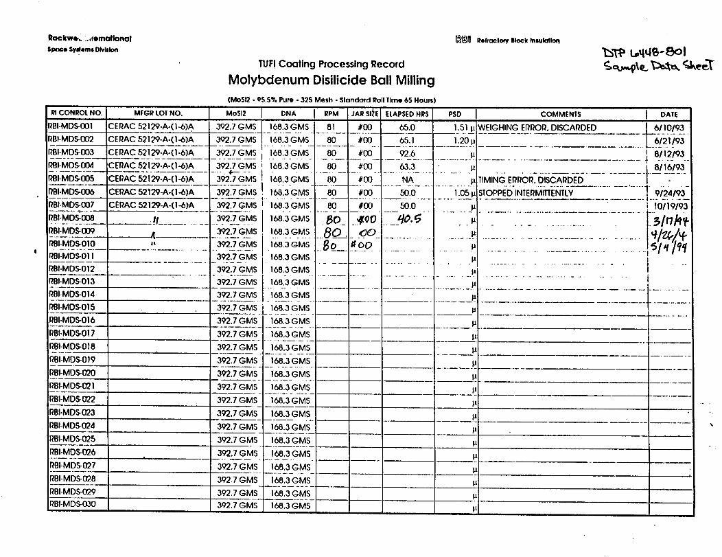
Rockwe_...mmallonal
SIX_e Syslem8Dlvblon
TUF! Coating Processing Record
Molybdenum Disilicide Ball Milling
_] Reffaclo_BlockInsulation
_T_ L_q_-8ol
_CONROtNO.i
I_BI-MDS-001
I_BI-MDS-002
I_BI-MDS-DO3
I_BI-MDS-DO4
I_BI-MDS-DO5
MrGR LOTNO.
'CERAC 52129-A-(I-6)A
CERAC 52129-A-(1-6)A
CEliAC 52129-A-(1-6)A
CERAC 52129-A-(1-6)A
CERAC 52129-A-(I-6)A
(MoSI2o9S.5% Pure- 325 Mesh - Standard Roll1line 65 Hours)
MoSI2
392.7GMS
392.7GMS
392.7GMS
392.7GMS
392.7GMS
DNA I .PM JARSt_'E!168.3GMS 81 #130
168.3GMS 80 #00
168.3GMS 80 #DO
168.3GMS 80 #DO
168.3GMS 80 #(30
ELAPSEDHRS PSD COMMEN|S
1.51 It :WEIGHING El_l_Or_.DISCAI_DED
1.20p
11
It
65.0
65.1
92.6
63.3
NA TIMING ERROR. DISCARDED
I DAIE
6110193
6121193
t 8112193
i 8119193
r_BI-MDS-DO6
RBI-MDS-007
RBI-MDS-DO8
I_BI-MDS-O09
rtBI-MDS-OIO
CERAC 52129-A-(I -6)A
CERAC 52129-A-(I-6)A
392.7GMS 16813"GMS....8[].... #00 .......-,50.-0-..............Ii0,5_STOPPI_D-iNTERi_ITIEI_TL-Y-..................I 9/24193-
39"2.7GMS!
168.3GMS
168.3GMS
1__.3GM.S168.3GMS
I_BI-MDS-011
RBI-MDS-012
RBI-MDS-013
RBI-MDS-014
_BI-MDS-015
RBI-MDS-O16
RBI-MDS-017
_BI-MDS-018
_BI-MDS-019
_BI-MDS-020i
RBI-MDS-021
RBI-MDS-022
RBI-MDS.-023
RBI-MDS-024
IIBI-MDS-025
RBI-MDS-026
RBI-MDS-027
RBI-MDS-028
I_BI-MDS..029
I?BI-MDS-0,30
392.7GMS
392.7GMS
80 #DO 50.0 It
•80_ .Zoo ....5o._ It
I o #o0 tJ
• ..s__l.........I.............................................................168.3GMS ......................................... p ................................
168.3GMS ........................................_ ................................
392.7GMS
3927G_S392.7GMS
392.7GMS 168.3GMS I,I
392.7GMS 168.3GMS It
392.7GMS L.!.68_3.GMs.
392.7GMS 168.3GMS 11
392.7GMS 168.3GMS It
--3.92.7GMS__ _168.3GMS It
_3.92..7GMS _I68:3G.MS ............... _......
392.7GMS _I..68.3GMS .... It,
_392.7GM_S_.__I68._3_GM_S_ p
392.7GMS 168.3GMS It
392.7GMS- 168.3_GMS. It
392.7GMS 168.3GMS
392.7GMS 168.3GMS
392.7GMS 168.3GMS
__!t .........
4
392.7GMS 168.3GMS
392,7 GMS 168.3GMS
392.7GMS 168.3GMS
392.7GMS 168.3GMS
10119193
.°
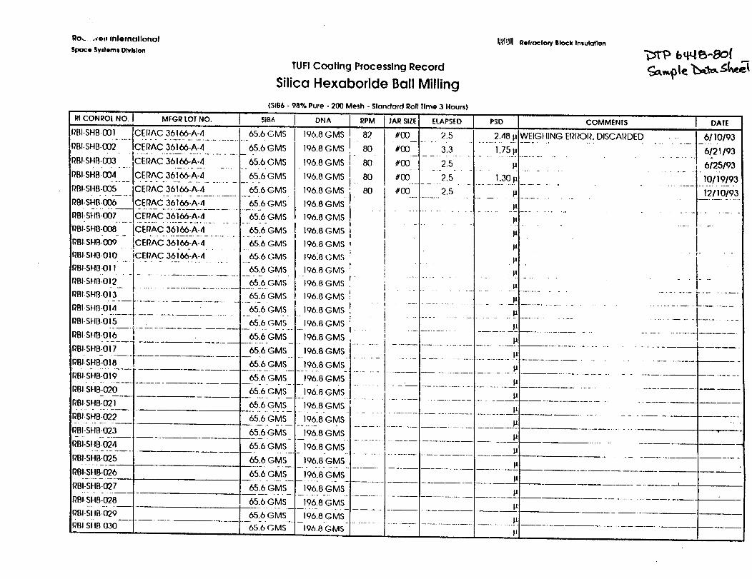
Ro,_..-_ett Inlemallonol
Spoce SystemsDlvblon
TUFf Coating Processing Record
Silica Hexaboride Ball Milling
IRI']II Reffoctow lll_k Insulation
(SiB6
RICONROt NO. I MFGR LOTNO. sin6 ] DHA
_,,.sHBoo, IceRAc361_-A-4 65.6cmsRBI-SHB-002-....ICE-PAC36-I-66-A-4.............65.6GMS
Rm.SH,.003-[C:_AC3-61-KA:4........._S.6GMS
RBI-SI4B-0D5 CERAC 36166-A-4 65.6 GMS
RBI-SHB-006 CERAC 36166-A-4 65.6 GMS
RB,-s,-,8-o07CeRAC361_-A-,, 656GMsRBI_SHB-00B-......C:I_I?AC36-I-66-'A-_I ......... 65"6-GMS
PBI-SHB-009 ]CERAC 361.66-A-4....... 65.6 GMS
IH}I-SHBOIO ICERAC 36166-A-4 65.6 GMS..... I .....................
RBI-SHB-011 ] 65.6 GMS
RBI-SHB-01_2......................... _65._6.GMS
RBI-SHB-OI3 ].......
RBI-SH8-01.4 .... J....RBI-SHB-OI5 I
pBIs.B-o!6 i
Rm-s"Bio!L_.tRBI-SHB-018 .
RBI.SEIB:O19___! .....
• 98% Pure - 200 Mesh - Standard Roll Time 3 Hours
196.8
196.8
196.8
196.8
I 196.8
196.8
196.8
]196.8I
196.8
19618
196.8
I 196.8
65.6GMS I 196.8
65.6 GMS 196.8
65.6 GMS 196.8
65.6GMS 1968__:6GMs_ 196.8
65.6 GMS 196.8I......
__ 65.6GMS 196.8
GMS
GMS
GMS
GMS
GMS
GMS
GMS
GMS
GMS
GMS
GMS
GMS
GMS
GMS
GMS
RPM
.. 82.80
i 80
. 80
. 80
IItI
I
I
i;
1 " "
T
,,I ....
I J'ARSIZE ELAPSED PSD t 'COMMENTS DATE
#00 2.5 2.48 p
#00._ 3.3 1.75 lJ
#00 2.5 p
,,oo..........2:S............_L_0._'L..........,oc........ 2.s .:
........................... 1_...........
P
...
t
P
P
P
P
WEIGt lING ERROR. DISCARDED . ,. 6/10193
GMS ;
GMS ...................... ' ........................ B!
GMS ........ :........................... _____.GMS
J - - i .......... i ........ -_'l-i ............
II ..... ! ................ t ......... I .........................
i "1 ............. i ........... i ............
I pt ....................................................
J IS,
6/21/93
6125/93
I0119193
1211O/93
!
II° ..
I
...........L22:........... i ..............
RBI SHB-020
RBI-SHB.021
RBI-SHB.022
RBI-SHB-023
RBI-SllB-024
RBI-SHB-025
RBI-SHB-D26
RBI-SHB-027
RBI-SHB-028
!RBI-SI IB-029
rim._itrran---
6.5.6GMS 196.8 GMS
-_, GMs 196.SGMS .......................
_ _.._6_GMS__._1.96_.8GMS- p............ !...... i....................
65.6 GMS 196.8 GMS
GMS- _9L8GMS65.6 I.... ---"--65:6 G M S ,"-196:8"GMS" I ....................... --_
1-96.8Gins_ L.............]
oo.o _--'-_-G"-'=.... .............. . _J"
- .... l i_....:-..... :- ............._...."--kc _"-'"_S-- -196.8GMS- -- .....
r--'-------t
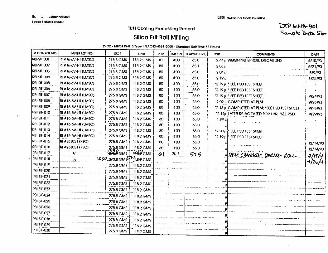
R_. ....demotJonal
Space SyslemsDlvlslon
RI CONROL NO.
RBI-SIF-001
RBI-SIF-O02
RBI-SIF-003
IJr'_ Reffacton/Block Iniulallon
TUFI Coaling Processing Record
Silica Frit Ball Milling
(5102 - MBOI I 5-013 Type II/[AC42-4561-3000 - Slondard Roll Time 65 Hours]
MFGR LOT NO. SIO2
RI #I6-6V-HT.(LMSC) I 275.8
RI# 16-6V-_Ht(LMSC) .......I 275_8
.......rlt16-6V-H!(LMSC) .......27_5.8
RBI-SIF-004 RI # 16-6V-HT (LMSC) 275.8
RBI-SIF-005 RI # 16-6V-HI (LMSC)
iRBI-S!F-Q06 RI # 16-6V-HT (LMSC)
RBI-SIF-D07 RI # 16-6V-HT (LMSC)
RBI-SIF-0O8 RI # 16-6V-HT (LMSC]
RBI-SIF-009 RI J 16-6V-HI (LMSC)
RBI-SIr--010 RI # 16-6V-HT (LMSC)
RBI.SIF-OII Pl # 16-6V-HI (LMSC)
RFJI-SIf.OI2 RI _ 16-6V-HI (LMSC)
RBISIF.OI3 RI # 16-6V-HI (LMSC)
RBI.SIF.OI4 fit# 16-6V-HI (LMSC)
GMS_
GMS.
GMS
GMS
215.8 GMS
275.8 GMS
' 275.8 GMS
I" 27518 GMSi
i 275.8 GMS
275.8 GMS
I 275.8 GMS
! 27518 GMS
! 27518GMSI: 275.8 GMS
DNA RPM
118.2GMS i 81I
118.2GMS i 80
118.2GMS I 80_o
118.2GMS I 80
118.2G MS 80
118,2GMS 80i
118.2 GMS 80
118.2GMS I 80I
118.2GMS _ 80._ . |
118.2GMS i 80!
I18.2 GMS ; 80I
118.2 GMS ! 80
118.2GMS 80
118.2GMS 80
• 80
80
oJAR SIZE ELAPSEDHRS.
#00 65.0
_oo........6S71#00 65.0
#00 65.0
#00 65.0
#00 65.0
#00 65.0
#00 65.0
#00 65.0
#00 65.0
#00 65.0
#00 65.0
#00 65.0
#IX) 65.0
!.... t.
!III
iI
Z!. -
II
iI
I
PSD COMMENIS j DATEi
RBI-SIF-015 RI.#28J051 (KSC]
RBI-SIF-016 RI #28J051 (KSC)
RBI-SIF-017 I I........................
RBI-SIF-OI8 ............ __ .......
RBI-SIF-019
I
I 275.8 GMS 118.2GMS.i
i 275.8 GMS 118.2GMS
11 o .....j_GMS _GMS
! 275.8GMS 118.2G-MS-
_'Bi:Sir:0"z0..... 1.................. i-:_75.8GMS--i]812 CMS-.............. G s;D_i i GM(
RBI-SIF-022 r--- 275 8 GMS , 118.2 GMS
- .................... GM -RBI-SIF-024 275.8 GMS 118.2GMS
RBI-SIF-025
RBI-SIF-026
RBI-SIF-027
RBI-SIF-028
RBI-SIF--029
275.8 GMS 118.2 GMS
......._75.-_GMS-'-hg2GMS-, 275.8 GMS 118.2GMS
275.8 GMS I18.2GMS
...... 275.8-G MS'- i i 8.2G MS
-- -275_-_ GMs ....11_2GMs-
2.44 I, WEIGHING ERROR, DISCARDED.......................
2.O8
2.o4;I2,1914
"2.191r° SEE PSD I'ESISHEET
'2,19Ir * SEE PSD lEST SHEET
"2.19II " SEE PSD TEST SHEET
2,02 rlCOMPLETED AT PLM
'2,13 I_COMPLETED AT PLM: *SEE PSD lEST SI-IEEI
*2.1311 I_iERRE--AGITAIIiD FOI_ IHI_:*SEE PSD
1.9914
14
'2.20 i_* SEE PSD IESISHEEI
"2.19 p ' SEE PSD TEST SHEET J
I 6110193!-'6/2i)93 "
.... !-8/9;93i. 8125193
• I .....
|
9124193
9/28/93i
9128193!
9129193
I I
#00 65.0 '. I .P ........................... _ 12114193
#00 65.0 I 14 ! "12114193
.......................i 1 ', .............................
TZL-_I_L,IL;n.:......;"- _. i _-..;-.i_2 ;L-
14
; .....77 .....................14
................................... J_14
27 July, 1994
LIGHTWEIGHT DURABLE TPS:ROBUSTNESS TESTING
Task 5
NCC2-9003
TA3.
Task Leader: Eric T. Watts, Rockwell - SSD
DTP 6449-801
Page 2
Table of Contents
1.0 BACKGROUND 4
2.0 GENERAL REQUIREMENTS 5
3.0 SUBTASK DESCRIPTIONS 6
3.1
3.1.13.1.2
3.1.8
DEFINE ADVERSE ENVIRONMENTS
Applicable DocumentsDetailed Requirements3.1.2.1 Launchpad Environments3.1.2.2 Flight Environments3.1.2.3 Orbital EnvironmentsSchedule
6
677
778
3.2 DEFINE TEST METHODS
3.2.1 Applicable Documents3.2.8 Schedule
888
3.3 RAIN3.3.13.3.23.3.33.3.43.3.53.3.6
EXPOSURE TESTING
Applicable DocumentsDetailed RequirementsTest Article
Test Procedure
Equipment/FacilitiesSchedule
9999
1010
10
3.4 FROST FORMATION TESTING3.4.13.4.23.4.33.4.43.4.53.4.6
Applicable DocumentsDetailed RequirementsTest ArticleTest Procedure
Equipment/FacilitiesSchedule
10101011111111
DTP 6449-801
Page 3
3.5 ICE FORMATION TESTING3.5.1
3.5.23.5.33.5.43.5.53.5.6
Applicable Documents
Detailed RequirementsTest ArticleTest Procedure
Equipment/FacilitiesSchedule
11121212121212
3.6 IMPACT RESISTANCE TESTING3.6.13.6.23.6.3
3.6.43.6.53.6.6
Applicable DocumentsDetailed RequirementsTest Article
Test Procedure
Equipment/FacilitiesSchedule
13
131313141414
3.7 DAMAGE REPAIRS AND PERFORMANCE EVALUATION3.7.13.7.23.7.33.7.43.7.53.7.6
Applicable DocumentsDetailed RequirementsTest ArticleTest Procedure
Equipment/FacilitiesSchedule
141414
151515
15
3.8 OTHER TESTING 15
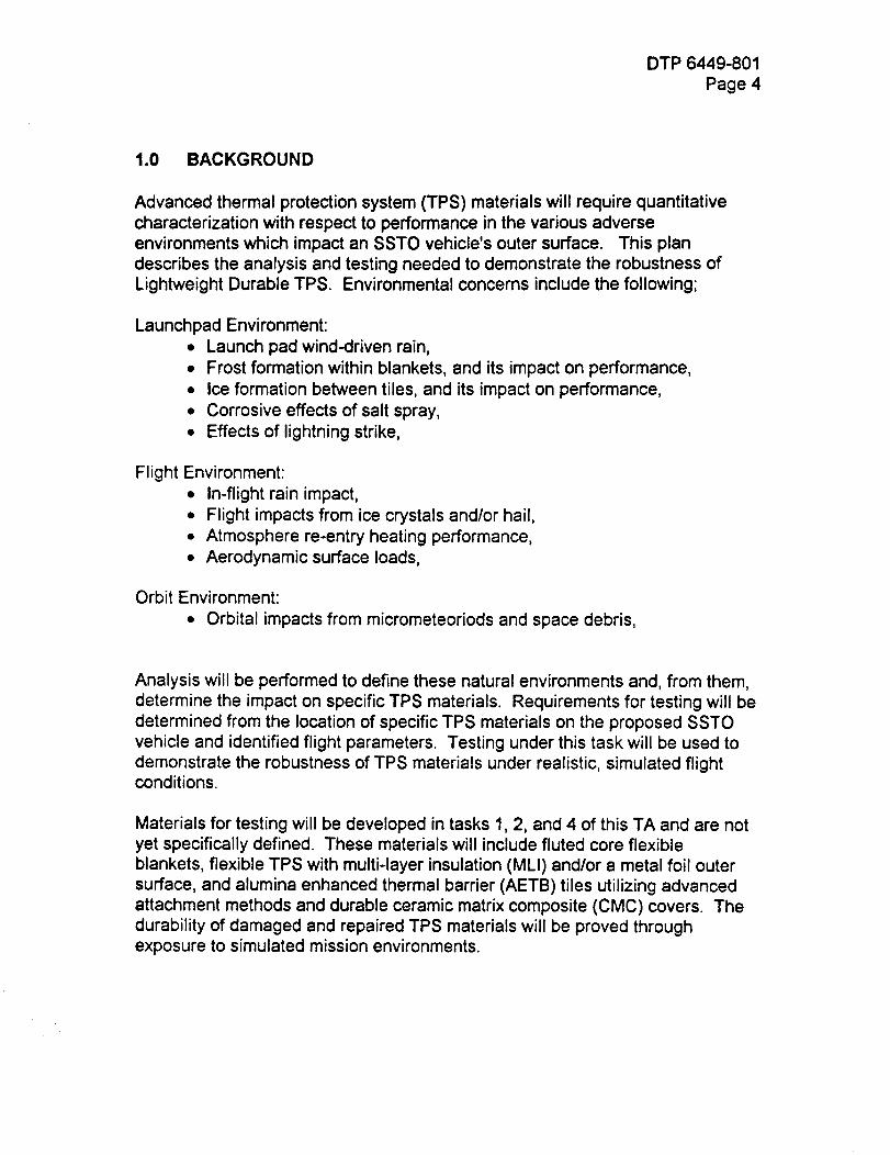
DTP 6449-801
Page 4
1.0 BACKGROUND
Advanced thermal protection system (TPS) materials will require quantitativecharacterization with respect to performance in the various adverseenvironments which impact an SSTO vehicle's outer surface. This plandescribes the analysis and testing needed to demonstrate the robustness ofLightweight Durable TPS. Environmental concerns include the following;
Launchpad Environment:• Launch pad wind-driven rain,
• Frost formation within blankets, and its impact on performance,
• Ice formation between tiles, and its impact on performance,• Corrosive effects of salt spray,
• Effects of lightning strike,
Flight Environment:• In-flight rain impact,
• Flight impacts from ice crystals and/or hail,
• Atmosphere re-entry heating performance,• Aerodynamic surface loads,
Orbit Environment:
• Orbital impacts from micrometeoriods and space debris,
Analysis will be performed to define these natural environments and, from them,
determine the impact on specific TPS materials. Requirements for testing will bedetermined from the location of specific TPS materials on the proposed SSTOvehicle and identified flight parameters. Testing under this task will be used todemonstrate the robustness of TPS materials under realistic, simulated flightconditions.
Materials for testing will be developed in tasks 1, 2, and 4 of this TA and are notyet specifically defined. These materials will include fluted core flexible
blankets, flexible TPS with multi-layer insulation (MLI) and/or a metal foil outersurface, and alumina enhanced thermal barrier (AETB) tiles utilizing advancedattachment methods and durable ceramic matrix composite (CMC) covers. The
durability of damaged and repaired TPS materials will be proved throughexposure to simulated mission environments.
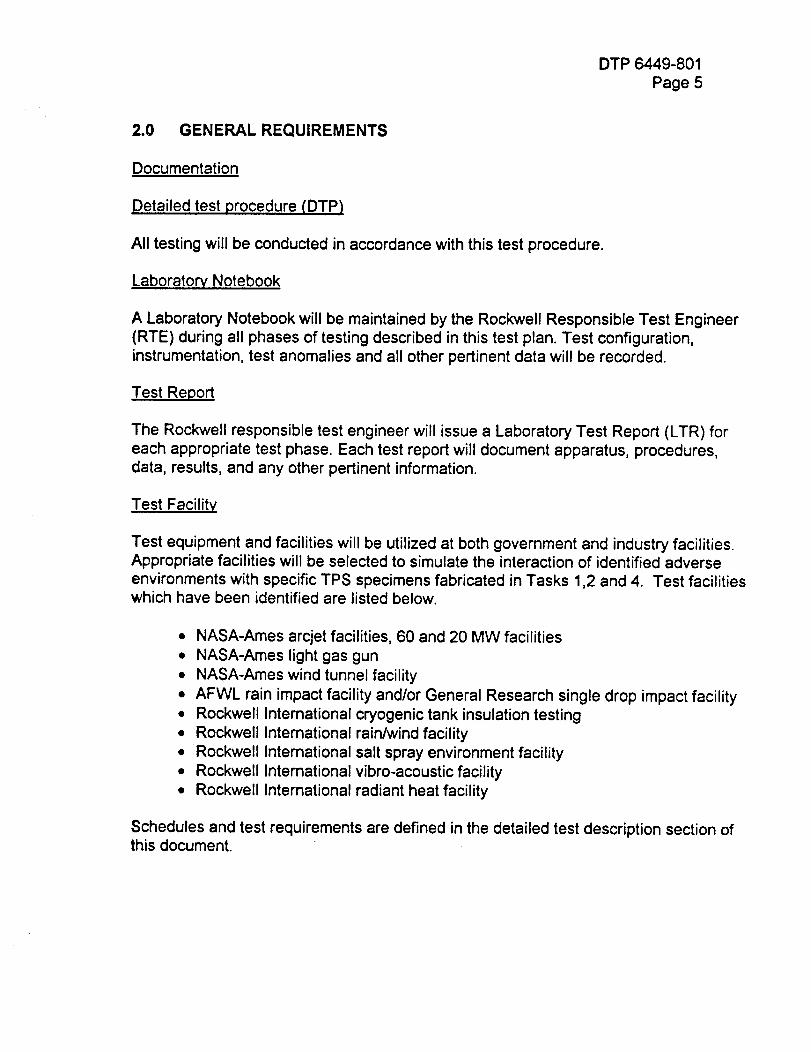
DTP 6449-801
Page 5
2.0 GENERAL REQUIREMENTS
Documentation
Detailed test procedure (DTP)
All testing will be conducted in accordance with this test procedure.
Laboratory Notebook
A Laboratory Notebook will be maintained by the Rockwell Responsible Test Engineer(RTE) during all phases of testing described in this test plan. Test configuration,instrumentation, test anomalies and all other pertinent data will be recorded.
Test Report
The Rockwell responsible test engineer will issue a Laboratory Test Report (LTR) foreach appropriate test phase. Each test report will document apparatus, procedures,data, results, and any other pertinent information.
Test Facility
Test equipment and facilities will be utilized at both government and industry facilities.Appropriate facilities will be selected to simulate the interaction of identified adverse
environments with specific TPS specimens fabricated in Tasks 1,2 and 4. Test facilitieswhich have been identified are listed below.
• NASA-Ames arcjet facilities, 60 and 20 MW facilities
• NASA-Ames light gas gun
• NASA-Ames wind tunnel facility
• AFWL rain impact facility and/or General Research single drop impact facility• Rockwell International cryogenic tank insulation testing• Rockwell International rain/wind facility• Rockwell International salt spray environment facility• Rockwell International vibro-acoustic facility
• Rockwell International radiant heat facility
Schedules and test requirements are defined in the detailed test description section ofthis document.
DTP 6449-801Page 6
Instrumentation
All measurement instrumentation shall be calibrated and have a decal showing a validcalibration date. A list of all test instrumentation will be maintained in a LaboratoryNotebook.
Test Conduct
The test program will be conducted under the direction of the task leader or adesignated representative.
3.0
3.1
3.1.1
SUBTASK DESCRIPTIONS
DEFINE ADVERSE ENVIRONMENTS
Applicable Documents
The documents listed below form a working list of reference material that will be
utilized in the quantitative definition of the adverse environments previouslymentioned.
1. Meteoroid and Space Debris Environment Definition. Don Kessler NASAreference document.
2. Orbital Debris Environment: An Update. Phan D. Dao,Phillips Laboratory,Geophysics Directorate, Hanscom AFB, MA. AIAA 94-0592
3. Space Station Program Natural Environment Definition For Design. RevisionA-June ,1991. NASA Space Station Freedom Program Office, Reston Virginia
4. LDEF Post Retrieval Symposium, Part One and Part Two. NASA ConferencePublications, AIAA
5. U.S. Weather Service Meteorological Data.
3.1.2 Detailed Requirements
DTP 6449-801
Page 7
A quantitative definition of adverse environments will be compiled from analysisof open literature, NASA and Rockwell technical reports, and all other availablesources. Some environments listed are well understood and testing forperformance in these presents little difficulty. Others, such as rain, ice andmeteor impact are not as well defined. Here the analysis on environmentdefinition will help drive testing requirements. Sections 3.1.2.1 through 3.1.2.3detail present concerns with respect to initial definitions.
3.1.2.1 Launchpad EnvironmentsAdverse environments associated with the launchpad include wind driven rain,the corrosive effects of salt air, and lightning discharge. Also of concern is theinteraction of rain and humidity with a filled cryogenic tank and the potential for
ice and frost formation. Wind driven rain, salt air conditions, and lightningstrikes are defined, and standard test methods will be employed. Evaluation ofpotential ice and frost formation will require analysis to define characteristic
temperatures of concept tank systems. The result of such analysis will definethe impact on specific TPS materials and test conditions.
3.1.2.2 Flight EnvironmentsAerodynamic and thermal analysis, based on the Rockwell SSTO vehicledesign, will be performed to define reentry heating and aerodynamic loads.
Specific body point environments will form the basis for defining specific TPSmaterial test requirements.
Analysis of flight impact phenomena (rain/ice/hail) will focus on defining weatherconditions in terms of quantitative data such as drop size distribution, altitudeprofiles, etc.. The potential for relaxing the current restrictions of no flightthrough rain/clouds will be evaluated. This work will also include an analysis todetermine the interaction of rain drops and ice with the flow field of the SSTOvehicle. This will provide necessary data on impact angles and drop distortionlevels at different locations on the vehicle. All analysis will be utilized to defineaccurate test conditions for specific TPS materials.
3.1.2.3 Orbital Environments
Of primary concern in orbit is the potential for catastrophic impact frommeteoroids and space debris. Current meteoroid and space debris environmentmodels will be analyzed together with identified vehicle attitudes and TPSmaterial locations to determine the most probable damaging particle sizes.Critical damage levels will be identified along with estimates of particle profilescapable of causing such damage. Testing methodology will flow from thisanalysis.
C-2_,
DTP 6449-801
Page 8
3.1.3 Schedule
Adverse environments definitions completeTPS/environment relationship definition complete
* Formal Milestone
15 October 1994"15 November 1994"
3.2 DEFINE TEST METHODS
It is the objective of this subtask to define test methods and specific operatingparameters to demonstrate the performance of TPS materials in adverseconditions. Available test methods will be reviewed and their capabilitiescompared to the requirements identified in the previously described analysis.
Methods, procedures, and operating parameters defined under this task willprovide a comprehensive plan for testing described in the remainder of this plan(sections 3.3 through 3.7).
3.2.1 Applicable Documents
The following will represent a working reference list of documents for evaluating
adverse environment simulating test methods.
1. ASTM standard test procedures
2. Facilities Capabilities
3.2.2 Schedule
Potential methods identified 1 November 1994
Test methods selected 1 April 1995Testing defined for adverse environments 30 June 1995"
* Formal Milestone
DTP 6449-801
Page 9
3.3 RAIN EXPOSURE TESTING
Testing will be performed to expose TPS materials to simulated rain at launch
and landing velocities. Primary objectives in this testing will be twofold; 1) toestablish a baseline for material comparison and 2) to evaluate materialperformance in the actual rain environment. The potential for flight through rainwill be evaluated. Two test methods have been identified for this testing, thestandard rotating-arm type test and so called single water drop impact testing.Single water drop testing allows impact of varied and precisely known dropsizes, allowing for analytic correlation with the natural rain environment.Rotating arm testing can be used as a basis for comparing materials. A testprogram including both types of testing is recommended. Details are TBD.
Wind-driven rain will be simulated and exposure tests conducted to investigatethe effects of launch pad weather on TPS blankets. Testing will be performed byblowing simulated rain at selected test specimens.
3.3.1 Applicable Documents
1. Appendix D, Standard Test Procedure - Rain Impact (Rotating Arm Facility)2. Appendix E, Standard Test Procedure - Rain Impact (Single Drop ImpactFacility)
3. Appendix F, Standard Test Procedure - Rain and Wind Impingement
3.3.2 Detailed Requirements
Detailed requirements for testing will be defined upon completion of subtask 3.2described in this document.
3.3.3 Test Article
Detailed drawings of test articles will be included in the final test plan and willconform to dimensions required by the test facility. General articles to be testedare listed below.
Wind/Rain Testing - 1 @ 15" tile array with durable cover- 1 @ 15"x 40" blanket on foam substrate
Rain Impact Testing - Method(s) TBD- 20 @ tile with durable cover- 20 @ blanket with metallic skin or ?
3.3.4 Test Procedure
DTP 6449-801
Page 10
Standard test procedures of the performing laboratories will be followed.Exceptions will be documented in this test plan.
3.3.5 Equipment/Facilities
Rotating arm rain erosion testing will be performed at the Air Force Facility,
Wright Laboratories / Materials Directorate (WL/MD). Single drop impact testingis available at General Research Corporation, Santa Barbara, Ca. Rain andwind impingement, simulating launchpad conditions, will be performed atRockwell - Laboratories, Test, and Materials Science Department.
3.3.6 Schedule
Begin test specimen design/fabricationBegin wind/rain testing (Rockwell)
WL/MD rain erosion testing (scheduled)Rain testing complete
30 June 199530 November 1995"
March-April 199630 July 1996"
* Formal Milestone
3.4 FROST FORMATION TESTING
Cryogenic tanks may cause the formation of frost within TPS blankets. Frost
may then impact blanket performance during flight. Testing will be performed todetermine if frost will form when blankets are installed over an insulated
cryogenic tank. If frost does form, then additional testing, to simulate missionenvironments, will be performed to investigate potential adverse effects.
3.4.1 Applicable Documents
1. Appendix B - Standard Test Procedure - Wind Tunnel Testing2. Appendix K - Standard Test Procedure - Venting3. Appendix H - Standard Test Procedure - Vibro-acoustics
4. Appendix A - Standard Test Procedure - Arcjet Facilities
3.4.2 Detailed Requirements
Detailed requirements for testing will be defined upon completion of subtask 3.2described in this document.
3.4.3 Test Article
DTP 6449-801
Page 11
Detailed drawings of test articles will be included in the final test plan and willconform to dimensions required by the test facility. General articles to be testedare listed below.
Frost Formation Testing - blanket installed over foamed cryogenic tank
Frosted Blanket Simulated Mission Performance Testing -1 @ 30"x 30" blanket on foam over Aluminum substrate
3.4.4 Test Procedure
Standard test procedures of the performing laboratories will be followed.Exceptions will be documented in this test plan.
3.4.5 Equipment/Facilities
Frost formation, vibro-acoustic, pressure profile, and cold soak testing will beperformed at Rockwell - Laboratories Test and Materials Science Department.Arcjet atmospheric entry heating simulation and wind tunnel tests will beperformed at NASA -Ames.
3.4.6 Schedule
Begin test specimen design/fabricationBegin test setup
Begin frost testingFrost testing complete - effects known
1 May 19951 July 199515 September 1995
29 February 1996"
* Formal Milestone
NOTE: No time has been scheduled for arcjet testing or wind tunnel testing
3.5 ICE FORMATION TESTING
Cryogenic tanks may cause the formation of ice in tile gaps. Ice may thenimpact tile performance during flight. Testing will be performed to determine ifice will form when tile is installed over an insulated cryogenic tank. If ice doesform, then additional testing, to simulate mission environments, will beperformed to investigate potential adverse effects.
DTP 6449-801Page 12
3.5.1 Applicable Documents
1. Appendix A - Standard Test Procedure - Arcjet Testing2. Appendix K - Standard Test Procedure - Venting Testing
3. Appendix H - Standard Test Procedure - Vibro-acoustic Testing
3.5.2 Detailed Requirements
Detailed requirements for testing will be defined upon completion of subtask 3.2described in this document.
3.5.3 Test Article
Detailed drawings of test articles will be included in the final test plan and willconform to dimensions required by the test facility. General articles to be testedare listed below.
Ice Formation Testing - five tile array installed over foamed cryogenic tank
Simulated Mission Performance Testing -Tile array on foam over Aluminum substrate
3.5.4 Test Procedure
Standard test procedures of the performing laboratories will be followed.Exceptions will be documented in this test plan.
3.5.5 Equipment/Facilities
Frost formation, vibro-acoustic, pressure profile, and cold soak testing will beperformed at Rockwell - Laboratories Test and Materials Science Department.Arcjet atmospheric entry heating simulation and wind tunnel tests will beperformed at NASA -Ames.
3.5.6 Schedule
Begin test specimen design/fabricationBegin ice testingIce testing complete - effects known
1 October 19951 December 1995
29 February 1996"
* Formal Milestone
NOTE: No time has been scheduled for arcjet testing - 60MW facility required.
DTP 6449-801
Page 13
3.6 IMPACT RESISTANCE TESTING
Hypervelocity impact testing will be performed to quantify potential damage frommeteoroids and space debris. Testing will encompass damaging particle sizesmost likely to be encountered in LEO orbits. Objectives for this testing includethe establishment of particle sizes capable of causing "critical" damage andother threshold damage levels. Analysis will be performed to evaluate damageat high, and experimentally inaccessible, velocities characteristic of meteoroids.
Testing will be performed to assess damage susceptibility from ice crystals and
hail impact. Specific natural environments will be simulated to evaluate damageand the potential for flight through these environments. The single drop facilityat General Research Corporation can provide this testing. Additional testmethods will be sought and evaluated for ice/hail impact testing.
TPS will be subjected to low velocity impacts to evaluate the resistance to"handling" type impacts such as wrench drops.
3.6.1 Applicable Documents
1. Appendix C- Standard Test Procedure - Debris Impact Testing2. Appendix E - Standard Test Procedure - Rain Impact (Single Drop)
3.6.2 Detailed Requirements
Detailed requirements for testing will be defined upon completion of subtask 3.2described in this document.
3.6.3 Test Article
Detailed drawings of test articles will be included in the final test plan and willconform to dimensions required by the test facility. General articles to be testedare listed below.
Meteoroid and Space Debris Testing - 10 @ blanket bonded to structure- 10 @ tile bonded to structure
Ice/Hail Impact Testing - 20 @ blanket coupons
- 20 @ tile coupons
Low Velocity Testing - 20-30 TPS coupons
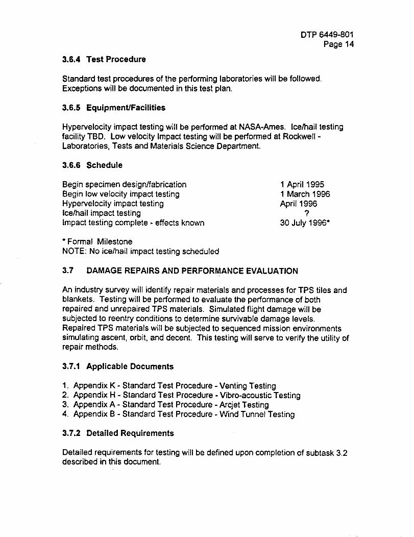
DTP 6449-801
Page 14
3.6.4 Test Procedure
Standard test procedures of the performing laboratories will be followed.
Exceptions will be documented in this test plan.
3.6.5 Equipment/Facilities
Hypervelocity impact testing will be performed at NASA-Ames. Ice/hail testing
facility TBD. Low velocity Impact testing will be performed at Rockwell -Laboratories, Tests and Materials Science Department.
3.6.6 Schedule
Begin specimen design/fabricationBegin low velocity impact testingHypervelocity impact testingIce/hail impact testingImpact testing complete - effects known
1 April 19951 March 1996
April 1996?
30 July 1996"
* Formal Milestone
NOTE: No ice/hail impact testing scheduled
3.7 DAMAGE REPAIRS AND PERFORMANCE EVALUATION
An industry survey will identify repair materials and processes for TPS tiles andblankets. Testing will be performed to evaluate the performance of both
repaired and unrepaired TPS materials. Simulated flight damage will besubjected to reentry conditions to determine survivable damage levels.Repaired TPS materials will be subjected to sequenced mission environmentssimulating ascent, orbit, and decent. This testing will serve to verify the utility ofrepair methods.
3.7.1 Applicable Documents
1. Appendix K - Standard Test Procedure - Venting Testing2. Appendix H - Standard Test Procedure - Vibro-acoustic Testing3. Appendix A - Standard Test Procedure - Arcjet Testing
4. Appendix B - Standard Test Procedure - Wind Tunnel Testing
3.7.2 Detailed Requirements
Detailed requirements for testing will be defined upon completion of subtask 3.2described in this document.
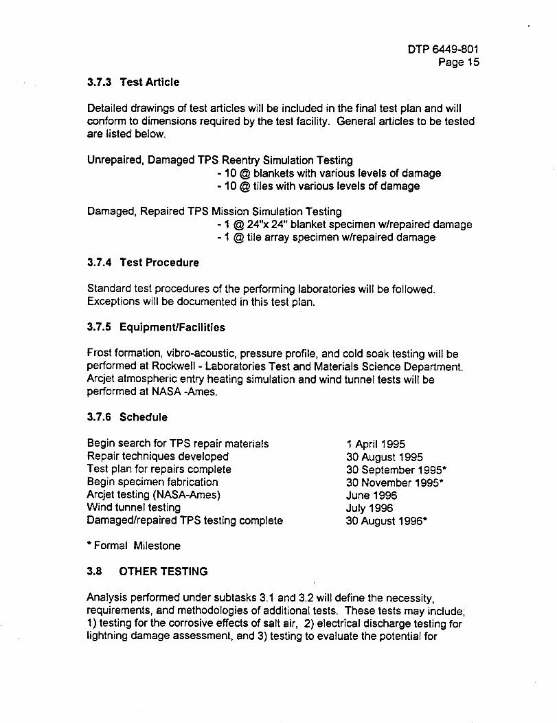
DTP 6449-801Page 15
3.7.3 Test Article
Detailed drawings of test articles will be included in the final test plan and willconform to dimensions required by the test facility. General articles to be testedare listed below.
Unrepaired, Damaged TPS Reentry Simulation Testing
- 10 @ blankets with various levels of damage- 10 @ tiles with various levels of damage
Damaged, Repaired TPS Mission Simulation Testing- 1 @ 24"x 24" blanket specimen w/repaired damage- 1 @ tile array specimen w/repaired damage
3.7.4 Test Procedure
Standard test procedures of the performing laboratories will be followed.Exceptions will be documented in this test plan.
3.7.5 Equipment/Facilities
Frost formation, vibro-acoustic, pressure profile, and cold soak testing will beperformed at Rockwell - Laboratories Test and Materials Science Department.Arcjet atmospheric entry heating simulation and wind tunnel tests will beperformed at NASA -Ames.
3.7.6 Schedule
Begin search for TPS repair materialsRepair techniques developed
Test plan for repairs completeBegin specimen fabrication
Arcjet testing (NASA-Ames)Wind tunnel testing
Damagedlrepaired TPS testing complete
1 April 199530 August 199530 September 1995"30 November 1995"June 1996
July 199630 August 1996"
* Formal Milestone
3.8 OTHER TESTING
Analysis performed under subtasks 3.1 and 3.2 will define the necessity,requirements, and methodologies of additional tests. These tests may include;1) testing for the corrosive effects of salt air, 2) electrical discharge testing forlightning damage assessment, and 3) testing to evaluate the potential for

DTP 6449-801
Page 16
trapping 02 and/or H 2 in the Velcro tile attachment interface, under developmentin Task 4.
July 28, 1994
Development Test Plan 6450
Integrated Health MonitoringNCC2--9003
TA-3
Task 6
Sub tasks 1 -8
Task Leaders
Tom Gormley, SSD Rockwell
Anne Patterson-Hine, Ames NASA
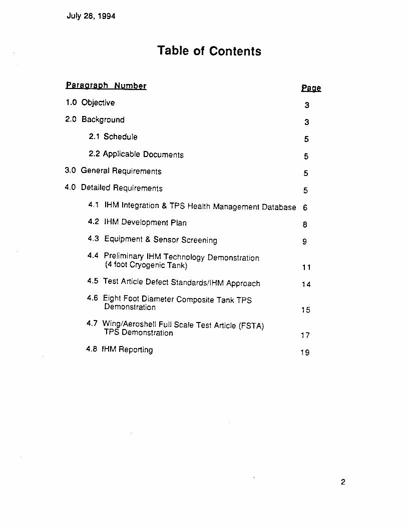
July 28, 1994
Table of Contents
Paragraph Number
1.0 Objective 3
2.0 Background 3
2.1 Schedule 5
2.2 Applicable Documents 5
3.0 General Requirements 5
4.0 Detailed Requirements 5
4.1 IHM Integration & TPS Health Management Database 6
4.2 IHM Development Plan 8
4.3 Equipment & Sensor Screening 9
4.4 Preliminary IHM Technology Demonstration(4 foot Cryogenic Tank) 11
4.5 Test Article Defect Standards/IHM Approach 14
4.6 Eight Foot Diameter Composite Tank TPSDemonstration 1 5
4.7 Wing/Aeroshell Full Scale Test Article (FSTA)TPS Demonstration 1 7
4.8 IHM Reporting 19
2
July 28, 1994
1.0 OBJECTIVE
1.1 The objective of this task is to identify cost-effective Integrated HealthManagement life cycle approaches for fault accommodation/detection,
automated test and checkout, and status determination of the thermal protectionsystem (TPS). Emphasis will be placed on optimizing robust TPS and sensortechnologies that support wide-area and localized coverage, automation,remote sensing and maintenance-on-demand design to operationphilosophies. Performance and maintainability envelopes for various TPS
options will be determined by surveying existing TPS applications (Shuttle,DOD) and by characterizing the TPS materials (material properties, failuremodes, functional environments, etc). Nondestuctive Evaluation/Inspection(NDE) sensor technologies will be selected and functionally demonstratedbased on expected failure modes and the technology capability to identify,locate, and quantify TPS system anomalies. The sensor technology informationwill be used to support the evaluation of TPS design alternatives and thedevelopment of the TPS/IHM systems for the 8 foot Reusable HydrogenCryogenic Tank System (TA1) and the Full Scale Wing Test Article (TA2) testprograms at NASA-MSFC and NASA-LaRC, respectively.
1.2 The TPS/IHM will evaluate design alternatives, assembly and verificationprocesses, establish inspection requirements, and identify NDE/NDI and IHMtechniques for use on lightweight durable TPS. TPS/IHM will perform tradesbetween more robust materials/designs and the capability of instrumentation
and inspection techniques to determine system status and TPS degradationand failures within low cost operations goals.
1.3 The TPS/IHM task will also establish an electronic IHM database that will
document the results of this test program; historical and current space ratedTPS maintainability profiles; and will support future SSTO operational
maintenance systems. These databases will include information on flight toflight performance of TPS and costs of maintenance (inspection, repair,replacement, refurbishment) and the fault analysis and decision algorithms thatare used in estimating and scheduling of maintenance and inspection timelinesand overall TPS operational readiness.
1.4 This development plan will follow an evolutionary path to the ultimatedevelopment of flight-quality systems. The developmental goals will be focused
on maturing the recommended technologies to TRL 6 and to establish flightready system design requirements.
2.0 BACKGROUND
2.1 TA3 (Ughtweight Durable TPS) IHM TASK Plan is one of three IHM
planned activities supporting the National Research Announcement 8-12 beingworked by NASA AMES and Rockwell Space Systems Division at Downey.This development plan will establish tasks leading to TPS/IHM design and
3
July 28, 1994
system requirements and will develop test plans for IHM coupon/panel sensorcharacterization, and TPS/IHM system validation tests on the TA1 and TA2 testarticles. This test plan will be updated throughout the program as required. Aglossary of IHM/NDE Terms will be written and will be included as Appendix Ato this document.
2.1.2 The primary goal of IHM for TPS (IHM/TPS) is to reduce the cost and timeassociated with pre-flight maintenance to a level where future SSTO
operational turnaround is like that currently found in military aircraft. TPSmaintenance will also be configured to avoid bottlenecking any work on thevehicle's other systems.
2.1.3 The most important factor in reducing TPS maintenance will be in theapplication of robust TPS materials while still meeting SSTO performancerequirements. However, it is envisioned that robustness will at some pointprohibit the SSTO from reaching its performance objectives. This is whenoperational health management concepts will have to be implemented. Evenwith robust TPS concepts, future SSTO's will experience TPS fatigue, failures,and damage during nominal operations over the vehicle's life cycle. Therefore,it is imperative to begin the development of a TPS/IHM system early in thedesign process in order to integrate IHM/'I'PS technology (sensors, software,etc.) into the SSTO system.
2.1.4 A comprehensive TPS/IHM system has both ground based monitoringand in-flight monitoring. Highly automated ground based monitoring andinspection supports maintenance on exception activities and is focused oninsuring operational readiness while the in-flight monitoring is focused on thesesame objectives as well as gathering data on the life cycle exposure to assesslong-term performance in an efficient manner. New promising NDE/NDI sensorand inspection technologies that are appropriate for both ground and in-flightmonitoring will be examined under this NRA task agreement.
2.1.5 This TPS/IHM task is one of many activities being pursued by the TA3Lightweight Durable TPS program. These other tasks will address keyconcerns on the durability of TPS surfaces, direct bonding of ceramic tiles,
attachment schemes, adverse operating environments, and reusability. Therewill be test articles leading to the re-establishment of fluted-core flexible
blankets, development of advanced flexible blankets that incorporate MLI, TPSbonded and mechanical attachments, and TPS robustness. These other TA3tasks will be fully integrated with the TPS/IHM effort. The TPS/IHMDevelopment Plan for TA-3 will provide:
1) NDE sensor screening process2) Coupon level IHM Technology Demonstration3) TPS IHM defect standards
4) Demonstration of TPS/IHM on a composite tank (8 ft.)5) Demonstration of TPS/IHM on a Wing FSTA6) Reporting
4
July 28, 1994
2.2 Schedule
MilestoneIHM Sensors ScreenedIHM Defect Standards
IHM Approached DevelopedIHM DemonstratedIHM Report
Date15 Oct. 94
30 Jun 9530 Nov 95
30 April 9630 Aug 96
2.3 Applicable Documents
"NRA8-12, Advanced Structures and TPS Technologies TA-3,Lightweight Durable Thermal Protection System Proposal"
3.0 GENERAL REQUIREMENTS
The established policies and practices of the testing facility will dictate generalrequirements. If a particular tests requires deviation from the performing testfacility's requirements an exception must be established.
4.0 DETAILED REQUIREMENTS
The detailed requirements outlined below are by sub tasks.
July 28, 1994
4.1 IHM Intearation & TPS Health Mana_aement Databas_
4.1.1. Requirement
Coordinate and provide IHM integration among NASA-ARC, MSFC, LaRC andSSD Team members. Provide integration between TA1, TA2 and TA3 NDE/IHMtasks as required.
4.1.1.a Estimated Completion Date: August 1996
4.1.1.b Task effort will run from May through August 1996
4.1.2 Approach
4.1.2.a. Integration will be accomplished in a variety of methods. Telecons willbe conducted between AMES and SSD IHM personnel at a minimum twice amonth or more frequently as required. Telecons will be conducted with TA-1and TA-2 as required.
4.1.2.b. Face to face sessions will occur as deemed by either team member.
4.1.2.c IHM requirements will be provided to TA3 Engineers and Scientists.
This will be done by attending design meetings and material & processingactivities conducted by TA3 Engineers.
4.1.2.d. An IHM person will attend all program review meetings.
4.2 TPS Health Management Database
4.2.1 Requirement
4.2.1.a A database will be developed for TPS materials performance and
failure mode information based on past experience with Shuttle operations.Additionally, laboratory and flight experiment data will be included, whenavailable. The database will also incorporate information from the sensor andNDE survey and evaluation to be performed under this task. Experimentalresults from coupon, panel, tank, and wing structure tests will be included. Thedatabase will be used to cross-correlate detection mechanisms with failuremodes. The costs for various detection strategies will be traded-off with the useof robust TPS materials.
4.2.1.b To begin the development of an TPS/IHM database and maximize itslong-range benefits the lessons learned from current operational experiencewith Shuttle TPS materials will be used to establish investment strategies. Agood understanding of the existing system andits strengths and weaknesses isnecessary before recommendation of new sensor technologies, inspectiontechniques, maintenance strategies or fault tolerance philosophies can beexplored.
6
July 28, 1994
4.2.1.¢ First, information on current Shuttle inspection, repair, refurbishment,and replacement procedures and costs will be used to construct a databasewhich highlights today's capability and cost structure. This database will beused to assess the current Shuttle "IHM/TPS" program and judge the impact ofrobust materials, advanced inspection techniques, and NDE/NDI sensor andinspection technologies on TPS maintenance costs. Property information onTPS materials is available from the existing TPSX database.
4.2.2 Approach
4.2.2.a. Requirements for the database will be generated by Ames andRockwell personnel. (7/94)
4.2.2.b Ames will survey COTS products based on the requirements for this
task and one or more products will be procured for database prototyping. (7/94)
4.2.2.c. Data format definitions will be established to enable data transferbetween Ames and Rockwell. (8/94)
4.2.2.d. Ames/SSD will define the database architecture. (9/94)
4.2.2.e Ames will populate the database with historical materials and flightdata. (ongoing throughout program)
4.2.2.f. Ames/Rockwell will incorporate TA-3 experiment data. Rockwell willprovide sensor and NDE data on diskette to Ames and Ames will incorporatethe data into the database. Ames incorporate local experiment data, too. (datacorrelates to experiment dates)
4.2.2.g Rockwell will provide Ames the results of the sensor and NDE surveyon diskette and Ames will incorporate that information into the database. (11/94)
4.2.2.h. Ames and Rockwell will identify costs associated with selected healthmonitoring strategies and the use of various TPS materials. Ames will
incorporate this information into the database. Part of this data may come fromthe results of efforts found in task 3 of TA1. (date TBD)
4.2.2.1 Ames will design and develop report formats which will summarizedatabase information and allow trade-off to the performed such as costs forsystem testability vs. use of robust materials. (date TBD)
7
July 28, 1994
4.2 IHM Development Plan
4.2.1 Requirement
The development plan (this document) will identify the process to: develop IHMdesign and system requirements, identify system faults that will have to bemonitored/managed during operations, predict/identify inspection planrequirements, and establish a preliminary test plan to be implemented duringthe Lightweight Durable TPS Program. The plan will identify preliminary TPSIHM plans for the 8 foot Composite tank test at MSFC and the Full Scale TestArticle structural test at LaRC.
4.2.1.a Estimated Completion Date: 29 July 1994; with periodic updates.
4.2.1.b. Initial task effort will run from May through July 1994.
4.2.2 Approach
4.2.2..a The development plan will be written by AMES and SSD IHMpersonnel. This plan will outline tasks providing requirements, approaches anddetailed test plans used on program hardware. This plan will be a dynamicdocument. Lessons learned during sensor selection will influence full scale testarticle testing and the 8 ft. tank testing at the end of this program. So, naturallytest plans for the activities will be general early on an get more specific alongthe way.
8
July 28, 1994
4.3 EauiDment and Sensor S_;reening
4.3.1 Requirement
TPS sensing technologies will be evaluated for both ground and in-flightapplication. Sensing and scanning technologies will be solicited fromNASA/DOD, Aerospace and Commercial Industries. Evaluation criteria will be
driven by system operational capability, sensor development cost, sensoroperations costs/benefits, sensor maturity and availability.
4.3.1.a. Estimated Completion Date: October 1994
4.3.1.b. Task effort will run from June through October 1994
4.3.1.c. Reports and findings will be entered into the TPS Health ManagementDatabase.
4.3.2 Approach
Analysis and sensor technology screening will be performed on IHM integrationand system analysis which will assist in the development of requirements. Thesensors screening process shall be divided into different technologies bases -NDE Conventional and Advanced Sensor. To gather data for sensorcomparisons and selection a Sensor Capability Classification Matrix will be
developed. During the screening process institutions possessing sensortechnologies will be explored. The Structural System Definition Statement willbe used to assist in evaluating sensor capability. Representative coupons andpanels, will be used in NDE sensor screening.
4.3.2.1 Sensor Technologies
4.3.2.1.a. Conventional are those NDE technologies that have
available/established methods, techniques, off the shelf equipment and trainingmaterials. Examples are but not limited to; x-ray, ultrasonic, penetrant, magneticparticle, eddy current, helium leak detection, visual and microwave.
4.3.2.1.b. Advanced are those NDE technologies that build on the
conventional NDE technologies and in some manner enhance the performanceof the methods either generically or application specific. Examples are but not
limited to; Laser Based Ultrasonic (LBU) Fiber Optics, Shearography,Computed Tomography and Thermography. Usually these are technologiesthat offer a unique approach or application of state-of-the-art technology.
4.3.2.2 Sensor Capability Classification Matrix
To assist in the weighing of each individual method a matrix will be developedto screen capabilities based on hardware requirements. This matrix is designed
July 28, 1994
to help identify the most promising sensor technology. The matrix will bedeveloped and documented during the sensor screening analysis.
4.3.2.3. Structural System Requirement Definition Statement
This statement will be generated through the TPS database analysis of failuremodes and insulation/TPS integrity issues.
4.3.2.4. Sensor Technology Survey
4.3.2.4.a. A sensor technology solicitation will be conducted of NRA8-12team players, Department of Defense, National Laboratories, aerospace andthe commercial communities. This survey will respond to the Sensor CapabilityClassification Matrix criteria and the Structural System requirement Definitionstatement. Uterary searches will be conducted to obtain a comprehensivecollection of state-of-the-art NDE reports. This provides not only currentbackground information but identifies key players in sensor application
development. A literary bibliography will be maintained. Additionally,conferences will be attended or minutes obtain to gather the most currentadvances.
4.3.4. APPLICABLE DOCUMENTS
STS Structural Bond Review Report, dated July 19, 1989
Investigation Analyses of the RCC R/H Panel #10 Impact from STS 45 (OV-104)
10
July 28, 1994
4.4. Coupon Level IHM Technoloov DemonstrationF.
4.4.1 Requirements
Study the requirements for the selection of TPS IHM technologies on couponsand 4 foot Aluminum Tank with composite inserts for integrated systemapplication. Evaluate sensor performance to non-intrusively determine the
health of TPS structure and all TPS failure modes. (Through analysis specificfailure modes will become identified for IHM monitoring.) Compare resultsagainst conventional NDE technologies. Preliminary tests will provide earlyinsight into system requirements prior to panel level IHM characterization tests.
4.4.1.a. Estimated Completion Date: May 1995
4.4o1.b. Task effort will run from November 1994 through May 1995.
4.4.1.¢. Reports and test results will be entered into the TPS HealthManagement Database.
4.4.2 Approach
4.4.2.1. Coupons Potential NDE sensors will be evaluated using fourteen(14) coupon level samples. These coupons will explore failure modes of TPSbonded to foam and TPS bonded to GR/Ep. Failure modes will be identified
using the TPS Health Management Database Failure modes agreed upon byAmes and Rockwell will be simulated on the coupons.
4.4.2.1.a. Panels will be IM7/977 material approximately .075" thick (nominallyan 8-ply [0_45/90]s layup or equivalent). The adhesives to be used to assemblethe structure may change as the vehicle prototype design concept becomesmore developed, but initial adhesive will be RTV 560 silicone adhesive for thetank structure. A "bumper" layer of Nextel cloth may be placed into the bondlinebetween the TPS and foam layers. The purpose of the Nextel layer is to absorband distribute impact loading when an incoming particle is encountered.
4.4.2.1.b. The TPS will include AAFRSI blankets (Rockwell configuration,fabricated per MA0605-3115), AETB tiles with TUFI coating, and FRXI
insulation. The foam layer will consist of low-density (approximately 3.2 pct)Rohacell foam in a variety of depths ranging from 0.5 inches to 1.25 inches.The TPS thickness will range from 0.25 inches FRXI to 3.0 inches TUFI tiles.
4.4.2.1.2. A second evaluation phase will occur when a direct bond (noRohacell Foam Insulation) of the TPS to the substructure is explored.
4.4.2.1.2.a Structure used in the direct bond task will be fabricated usinggraphite/bismalimide. Specimens requiring core will be bonded using American
11
July 28, 1994
Cyanimides HT424 adhesive. All AETB tile will be bonded to the structureusing General Electric's RTV 560 silicon adhesive with a nominal bond linethickness of 7-10 mils. 6x6" AETB-12 will be bonded to 8x10" substrate. 6x6"
AETB-12 will be bonded to a 12x14" substrate. Specimens will be adhesivelybonded using RTV 560 (MB0130-119 TYII) of bondline thickness from 10 to 20mils and by the use of structural adhesive HT 424.AETB-12 tile with attachedCMC cover will be direct bonded and bonded using .090" thick strain isolatorpad.
4.4.2.1.2.b. Selected NDE sensor technology will evaluate the 15x40" seventile array panel if available and applicable.
4.4.3 4 ft. Tank. SSD will use a four foot diameter aluminum cryogenic tankwith a composite panel insert. This tank will be used as an early test bed for IHMsystem requirements and NDE sensor access and hardware configurationimpacts. Insulation and TPS will be mounted on the exterior of the tank and then
it will be loaded and unloaded with liquid nitrogen.
4.4.2.a. Test Objective
Establish preliminary TPS IHM sensor performance to monitor TPS failuremodes.
4.4.2.b. Test Article Description
Coupons as described in 4.4.2.1 and an integrated sub scale (4 ft. diameter al.)cryogenic test article containing TPS and insulation. Damage other thanpreinduced flaws will be induced according to the test parameters in tasks 2, 4,and 5.
4.4.2.c. Test Description
Evaluate potential NDE sensors and selected IHM technologies in an integratedsystem environment during cryogenic loading and detanking tests.
4.4.2.d. Potential Instrumentation
Acoustic emission, ultrasonics, fiber optics, thermography, shearography,radiography.
4.4.2.e. Test Location
Rockwell SSD, Downey, California.
4.4.3 APPLICABLE DOCUMENTS
STS Structural Bond Review Report, dated July 19, 1989
12

July 28, 1994
Investigation Analyses of the RCC R/H Panel #10 Impact from STS 45 (0V-104)
13
July 28, 1994
4.5. Test Article Defect Standards/IHM ADDroa_:h
4.5.1 Requirements
Using the TPS Health Management Database (4.2) failure mode analysis,establish full scale test article defect requirements that need to be monitored
and managed during the MSFC 8-ft Composite Tank and the LaRC WingStructure FSTA tests. This effort will identify requirements to a lower level ofdetail than requirements identified in the IHM plan development, i.e.. debondsizes to be monitored. The IHM system approach to accommodate these
standards will be further refined based on preliminary IHM technologydemonstrations on the 4 ft. cryogenic tank.
4.5.1.a. Estimated Completion Date: 6 December 1995
4.5.1.b. Task effort will run from November 1994 through November 1995
4.5.1.c. Reports and findings will be entered into the TPS Health ManagementDatabase.
4.5.2 Approach
TBD
4.5.3 APPLICABLE DOCUMENTS
STS Structural Bond Review Report, dated July 19, 1989
Investigation Analyses of the RCC R/H Panel #10 Impact from STS 45 (OV-104)
14
July 28, 1994
4.6. Eiaht Foot Diameter Composite Tank TPS IHM Demonstration
4.6.1 Requirement
This task first characterizes the preferred sensor technologies on an insulatedcomposite panel with varying TPS options. Failure modes are intentionallyintroduced into the test specimens. This panel level effort will establish sensorperformance to monitor TPS/failure modes, and impact damage assessment.The task then proceeds to integrate IHM requirements and the preferredtechnologies into the MSFC 8 ft. composite tank structural tests under cryogenicloading and detanking conditions to monitor failure modes and TPS integrity,cryopumping, and leakage.
4.6.1.a. Estimated Completion Date is June 1996.
4.6.1.b. Task effort will run from December 1995 through June 1996.
4.6.1.¢. Reports and test results will be entered into the TPS HealthManagement Database.
4.6.2 Approach
4.6.2.1. The NDE technology used during the final demonstration of anintegrated IHM system operating on the 8 ft. diameter tank will be demonstratedon a representative section of the tank. The NDE or sensor technology will havebeen previously screened and only the most promising technologies will beevaluated.
4.6.2.2. The test panel identified as IHM-1 under TA-1 will have thegraphite/epoxy substructure and insulation/TPS mounted. This panelconfiguration will be an accurate representation of the tank. Pre-induced flawswill have been placed to represent failure modes for the Insulation and TPSattachment.
4.6.2.3. Finite element models will be used in the identification of flaws sizeand location of critical areas. These models will predict the outcome of the NDEtest results which will improve scale up efforts, by providing sensor placementinformation, such as location, and sensor coverage for reliable IHM monitoring.
4.6.2.4. IHM-1 panel will be baselined using conventional NDE methods andthe results will be correlated to selected sensor technologies used duringtesting of the panel. This panel will be tested under load. Successful sensorswill be evaluated with IHM requirements and the 8 ft tanks operationalrequirements for applicability to monitoring of the tank.
15
July 28, 1994
4.6.2.1.a Test Objective
Characterize and verify sensor technology to detect TPS and Insulation failuremodes and integrity.
4.6.2.1.b. Test Article Description
The panel's substructure will be manufactured under IHM activity in TA1. Thispanel has been identified as IHM-1. It is a 30 inch by 30 inch graphite/epoxystiffened panel. Insulation and TPS selected by TA-3 Engineering will bemounted on IHM with pre-induced flaws (representing selected failure modes).This work will be accomplished at the SSD Downey Composite Laboratory.
4.6.2.1.c. Test Description
Characterize TPS IHM sensors.
4.6.2.1.d. Potential Instrumentation
Acoustic emission, ultrasonics, fiber optics, thermography, shearography, andlaser based ultrasonics.
4.6.2.2. Eight Foot Composite Tank Insulation/TPS IHM Demonstration
4.6.2.2.a. Test Objective
Characterize and verify sensor technology performance on a graphite/epoxycomposite tank with insulation and TPS for leakage during cryopumping, andselected failure modes for TPS/insulation under load.
4.6.2.2.b. Test Article Description
The TA-1 8 foot diameter composite tank with insulation and TPS.
4.6.2.2.c. Test Description
The IHM integrated system will be evaluated under cryogenic environment.
4.6.2.2.d. Potential Instrumentation
Only those sensors that can demonstrate the required sensitivity and resolutionon the IHM--1 panel, can operate under the conditions required during testing,and can be successfully integrated into the IHM system will be used.
4.6.2.2.e. Test Location
MSFC
APPLICABLE DOCUMENTS
16
July 28, 1994
4.7.0 Winq/Aer0shell Full Scale Test Article (FSTA_ TP_Demonstreti0n
4.7.1 Requirement
Characterize the preferred sensor technologies on an insulated wing compositepanel with varying TPS options. Flaws are intentionally introduced into thepanel. Characterization results will establish sensor performance to monitorTPS/wing failure modes, and TPS integrity after impact damage. The task then
proceeds to integrate IHM requirements and the sensor technologies into theLaRC Wing FSTA structural tests to monitor TPS integrity and disbonds.
4.7.1.e. Estimated Completion Date is August 1996.
4.7.1.b. Task effort will run from January 1996 through August 1996.
4.7.1.c. Reports and test results will be entered into the TPS HealthManagement Database.
4.7.2 Approach
4.7.2.a The NDE technology used during the final demonstration of an
integrated IHM system operating on the TA2 FSTA wing will be demonstrated
before hand on a representative section of the structure. The NDE technologyapplied will be the product of paragraph 4.3.
4.7.2.b. The test panel fabricated under TA-2 will have a graphite/epoxysubstructure and TPS mounted to the external surface. This panel configurationwill be an accurate representation. TPS failure modes will also be represented.Any flaws size requirements will come from TA-3 Engineering.
4.7.2.¢. This test panel will be baselined using conventional NDE methods
and the results will be correlated to advanced NDE sensors used during testingof the panel. This panel will be test under load. Successful sensors will be
evaluated with IHM requirements and the FSTA's operational requirements forapplicability to monitor the wing during testing.
4.7.2.1.a Test Objective
Characterize and verify selected sensor technology to detect wing panel TPSfailure modes and TPS conditions at panel level.
4.7.2.1.b. Test Article Description
The substructure will be fabricated under TA-2 IHM activities. This panel will beapproximately 18" by 36" with various TPS options attached.
17
July 28, 1994
4.7.2.1.c. Test Description
The panel will be loaded to simulate flight conditions. Sensors will be evaluatedduring loading to characterize the TPS IHM potential.
4.7.2.1.d. Potential Instrumentation
Acoustic emission, ultrasonic, fiber optics, thermography, shearography, andothers.
APPLICABLE DOCUMENTS
STS Structural Bond Review Report, dated July 19, 1989
Investigation Analyses of the RCC R/H Panel #10 Impact from STS 45 (OV-104)
4.7.2.2. FSTA IHM Demonstration
4.7.2.2..a Test Objective
Characterize and verify under test conditions sensor technology on the FSTAwing with TPS attached.
4.7.2.2.b Test Article Description
The TA-2 Full Scale Test Article with TPS and NDE sensors.
4.7.2.2.c Test Description
The IHM integrated system will be evaluated under loaded conditions.
4.7.2.2.d Potential Instrumentation
Only those sensors that can demonstrate the required sensitivity and resolutionon the wing panel, can operate under the conditions required during testing,and can be successfully integrated into the IHM system will be used.
4.7.2.2.e Test Location
LaRC
APPLICABLE DOCUMENTS
STS Structural Bond Review Report, dated July 19, 1989
Investigation Analyses of the RCC R/H Panel #10 Impact from STS 45 (OV-104)
18
July 28, 1994
4.8.1 Requirement
4.1_. IHM Reportin_
4.8.1.a. Finalize IHM Program documentation, test results, lessons learnedand recommendations for further efforts.
4.8.1.b. Updated versions of the TPS Health Management Database will befurnished at reporting dates.
4.8.1.¢. Reports will be entered into the TPS Health Management Database.
4.8.2 Approach
Quarterly and the final report will be the efforts of both AMES and SSD. SSDwill have primary responsibility.
19
APPENDICES
Appendix A,
Appendix B,
Appendix C,
Appendix D,
Appendix E,
Appendix F,
Appendix G,
Appendix H,
Appendix I,
Appendix J,
Appendix K,
Appendix L,
Arcjet facilities, 60 and 20 MW
Wind tunnel
Debris impact
Rain impact
Rain impact, single drop
Rain/wind
Salt Spray
Vibroacoustics
Vibration
Radiant exposure
Venting
Air Impingement
DTP 6451-810
DTP 6451-811
DTP 6451-812
DTP 6451-813
DTP 6451-814
DTP 6451-815
DTP 645 I-816
DTP 645 I-817
DTP 6451-818
DTP 6451-819
DTP 6451-820
DTP 6451-822

APPENDIX A
ARCJET TESTING
DTP 6451-810
PAGE 1
PLASMA ARCDETAILED TEST PROCEDURE
NRA 8-12, SSTO TA-3
INTRODUCTION:
This Detailed Test Procedure (DTP) defines the plasma arc exposure testing for theTPS material developed in the different tasks of TA3. The specimen material, size andconfiguration will be specified by each task. The plasma arc tests will be performed atthe NASA/AMES plasma test facilities. There are several different facilities includingthe Aerodynamic Heating Facility (20 MW), the Interaction Heating Facility (60 MW), thePanel Test Facility (20 MW), and the Turbulent Flow Duct (20 MW). Each facility has itsunique capabilities in simulating different heating environments to test different types oftest articles.
TEST OBJECTIVE
To evaluate the temperature capability, surface durability and backface temperature ofthe TPS materials in the simulated aerodynamic heating environment of the plasma arctest. Thermal conductivity and catalysity will be determined by the temperature dataand re-radiative heat flux measurements obtained in the test. A secondary objective is
to correlate experimental data with thermal and computer generated thermal models.
SCOPE
This document describes testing of each task and is limited to those tests. The actualfacility operations and related procedures will be the responsibility of NASA/AMES.Changes to this plan which are in the scope of the test request may be made by"Redline" changes approved by the Responsible Test Engineer, and documented in theLaboratory Notebook.
APPLICABLE DOCUMENTS
• Ames Research Center- Arc Jet Testing Guide
• Quality Assurance Specification and Quality Requirements for off site test, MT0802-105A
• The Laboratory & Test (L&T) administrative document : Laboratory Request (LR)
• Rockwell Laboratory notebook for recording observations during testing.
• NASA Ames specification "9SP-9001-XR5, Thermocouple Probe Fabrication andInstallation Procedure for Flexible Insulation"
GENERAL REQUIREMENTS
Handling of test panelsWhen handling the test panels or any part of the test specimen assembly clean whitecotton gloves or equivalent shall be worn to prevent contamination. Any specimenphysical damage such as accidental surface contamination will be documented in theLaboratory Notebook by the Responsible Test Engineer (RTE).
DTP 6451-810PAGE 2
When handling SiC fibers, Neoprene type (Edmont, Sol-Vex #37-145 or equivalent )gloves should be worn. All precautions indicated in the Material Safety Data Sheet(MSDS) for the SiC fibers should be carefully followed. After thermal exposure of theSiC test articles, take caution to prevent dispersion of fibers.
Notice of Test
The RTE shall be notified in advance of any scheduled test.Photographic CoverageColor photographs will be taken of the test panels when any visual variance from initialcondition is noticed.
InspectionA general visual inspection of the test panel and fixture shall be made prior to the startof the test. A complete visual inspection along with color photographs shall be madeafter each test in order to determine any damage that might occur.
ReportThe test agency shall provide all test data to the RTE. The RTE shall be responsible forpublishing a Laboratory Test Report (LTR). The technical content of the LTR shall bethe responsibility both the test agency and the RTE.
TEST SPECIMEN PREPARATION
The material specimen fabrication, instrumentation and assembly shall be by Rockwellto the requirements and procedures to be defined in each of the tasks. The test will
A test configuration found in an AFRSI certification report (Panel Test Facility, 20 MW) isused as an example in this DTP (See Fig. 1 - 5). Modification will be made accordingto the requirements of each task.
For testing to be conducted at the Panel Test Facility, aluminum plates (6061 - T6) canbe fabricated as carrier plates. Plates with appropriate dimensions (to be defined byeach task) shall be cut, etched per MA0110-305 and primed per MA0608-301 code 00-AA-21 -XX.
Specimen shall be bonded to the aluminum plates per MA0 606-317.
TEST PANEL INSTRUMENTATION
Appropriate number and type of thermocouples for the required temperature range willbe instrumented in the specimens to the requirements of each different task.Appropriate control articles with known thermal properties will be utilized (e.g. FRCItiles) as reference and for calibration purposes. Thermocouples will be instrumented
in the control articles accordingly. The locations of the instrumentation is TBD for eachtask. NASA Ames specification "9SP-9001-XR5, Thermocouple Probe Fabrication andInstallation Procedure for Flexible Insulation" will be used as a guideline.
TEST SETUP DESCRIPTION
The plasma exposure will be conducted at NASA Ames test facilities. The facility,specimen and sample holder configurations, and test parameters are TBD according tothe purposes of the testing of the task.
DTP 6451-810
PAGE 3
Rockwell will assemble the specimen and instrumentation to conform to NASA Ames
test fixture configuration. For the Panel Test Facility specimen configuration, in someinstances, a cooling plate will be used on the back surface of the test panel to limit the
bondline (IML) temperatures to a maximum of 350°F. In other instances, adiabatic back
wall might be necessary. The exposed portion of the test specimen aluminum carrierplate shall be closed out using glasrock or other rigid RSI.
TEST PROCEDURE
NASA/Ames shall provide the facility apparatus, setup, data acquisition, data reductionand facility procedures for plasma exposure.
Test Conditions
The OML surface of the specimens shall be exposed to a heating environment andduration time defined in the test matrix (See Table I as an example) which is TBD for
each task resulting in the control article surface temperature to be defined for theparticular type of control article material at minimum attainable chamber pressure.Thermocouple will be instrumented at the backface of the test specimen to monitor thetemperature there. For the Panel Test Facility, maximum soak and temperature on the
IML shall be limited to 3500F by use of a coldplate or other technique chosen by the
test agency and approved by the RTE. An optical pyrometer shall be used to monitorthe surface temperature of the blankets (approximately 2 microns narrow band sensorfor best results). The pyrometer data acquisition shall be non-interference with theplasma test exposures.
Routine test procedures shall be the responsibility of the testing agency (NASA/Ames).
Pre-test Cafibration
The test environment of NASA/Ames 20 MW and 60 MW plasma arc facilities shall be
demonstrated by a series of runs using the control article (provided by Rockwell)calibration model instrumented with appropriate type of thermocouples.
Test specimens shall be visually inspected before insertion into the test chamber. After
specimens are in the test chamber, verify all components are properly fitted.
After calibrations are made each test specimen shall be placed in the test fixture holderand exposed thermally to plasma flow as indicated in the test matrix.
Prior to starting a test run the thermocouples shall be reading properly at ambienttemperature and the test instrumentation shall be checked for continuity.
All data shall be recorded at specified TBD sampling rate. Test data shall be recorded
on any medium per facility capability. The tabulated engineering data, temperature,pressures and time parameters shall be furnished by NASA/Ames to the RTE at thecompletion of each test run.
TEST ARTICLE DISPOSITION
At the completion of the test the test specimens shall be returned to Rockwell, SpaceSystems Division, Laboratories and Test, Dept. 284 for retention.

Table I - Sample Test
Specimen ID/battin_
Tyranno TABI/Saffil
Tyranno TABl/Saffil
Tyranno TABI/440
Tyranno TABI/440
Thermal Exposure
1500F
Matrix
DTP 6451-810
PAGE 4
Duration
17 min
2000F 17 min
1500F 17 min
2000F 17 min
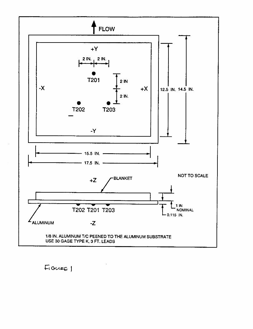
t FLOW
-X
+Y
T201
• • -T202 T203
m
2 IN
2 IN.
+X
-y
L15.5 IN.
17.5 IN.
-!
+Z
BLANKET
A_LUMINUM
W V V
T202 T201 T203
-Z
;I
12.5 IN. 14.5 IN.
m
._J_
NOT TO SCALE
I
I i L 1IN/ NOMINAL1"-0.115 IN.
1/8 IN. ALUMINUM TIC PEENED TO THE ALUMINUM SUBSTRATEUSE 30 GAGE TYPE K, 3 FT. LEADS
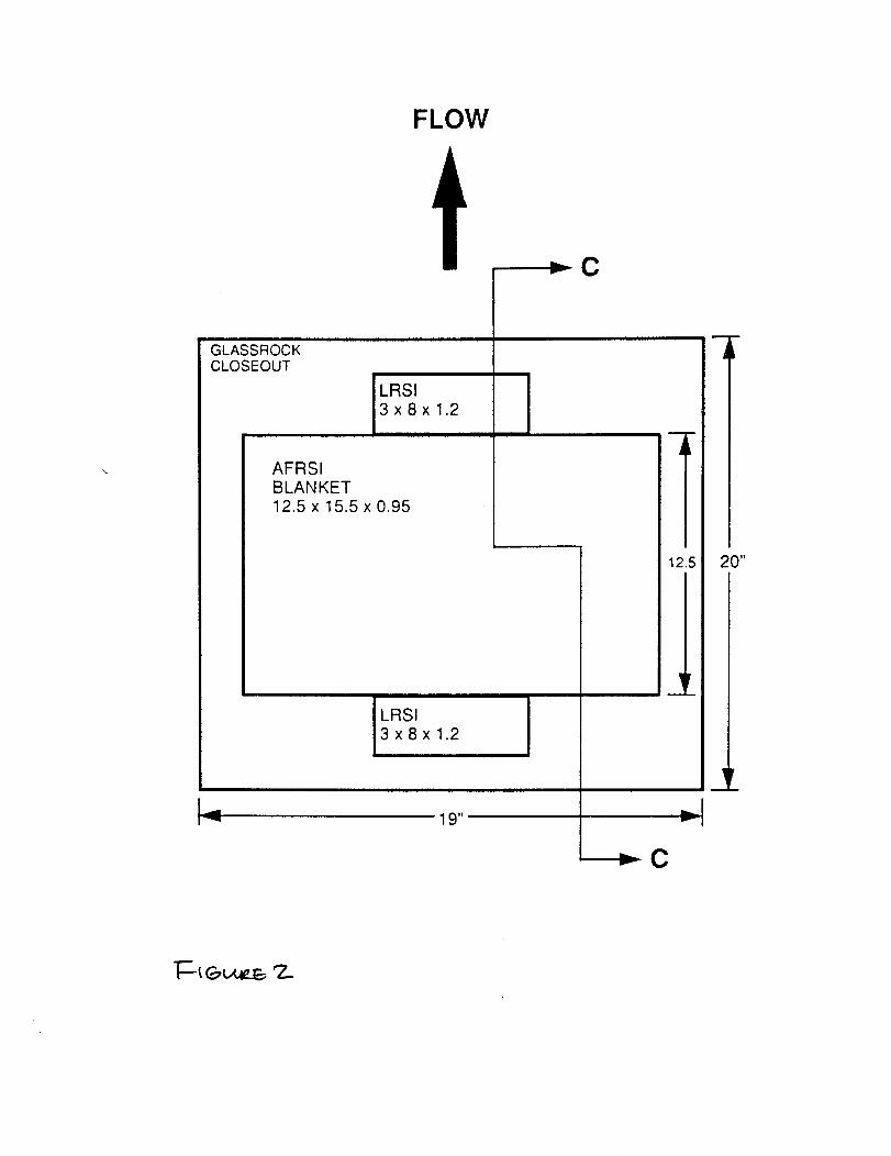
FLOW
GLASSROCKCLOSEOUT
LRSI3x8x1.2
AFRSIBLANKET12.5 x 15.5 x 0.95
19"_
12.5
¥
.I1,,-
----I_ C
20"
F--_ _M4z.B 'Z..
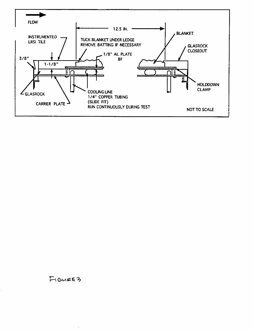
FLOW
,4, 12.5 IN.
TUCK BLANKET UNDER LEDGE /INSTRUMENTED "-7
LRSI TILE /
3/8" _ p
BLANKET
GLASROCKREMOVE BATTING IF NECESSARY
'_ 1-1/8"|
RUN CONTINUOUSLY DURING "rESTNOT TO SCALE
HOLDDOWN
CLAMP
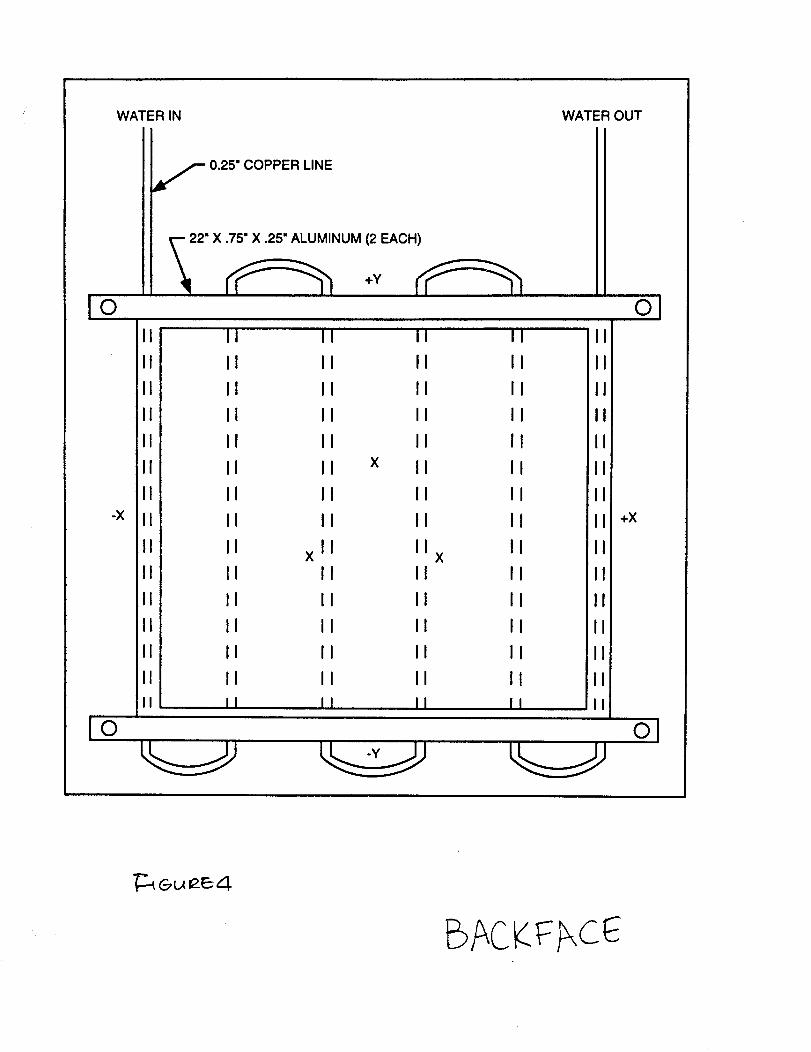
WATER IN WATER OUT
f 0.25" COPPER LINE
O
--- 22" X .75" X .25" ALUMINUM (2 EACH)
O
!©
-X
II
II
II
II
II
II
II
II
II
II
II
II
II
II
II
II
II
II
II
II
II
II
II
IIX
II
II
II
II
II
II
X
II II
II II
II II
II II
II II
II II
II II
II II
II IIX
II II
II II
II II
II II
II II
II II
II
II
II
II
II
II
II
I +x
I
I
II
oJ
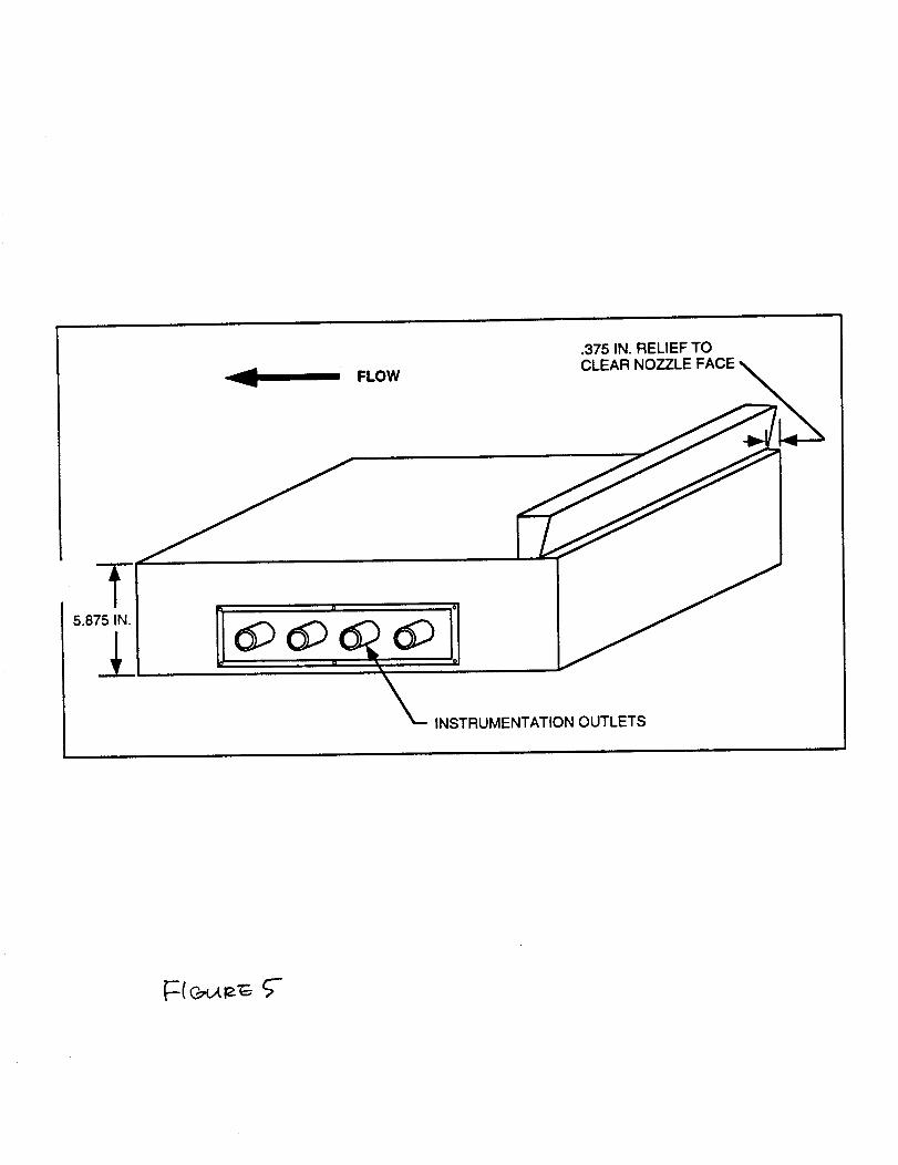
.375 IN. RELIEF TO
_ FLOW CLEAR NOZZLE FACE
IN
5.875 IN.
APPENDIX B
WIND TUNNEL TESTING
DTP 6451-811PAGE 1
Wind Tunnel Testing of TPS MaterialsDetailed Test Plan
SSTO/Access to Space NRA 8-12
Cooperative Agreement NCC2-9003TA-3 Light Weight Durable TPS
prepared by
David WittmanRockwell SSD
DTP 6451-811PAGE 2
Table of Contents
Section
1.0
2.0
3.0
4.0
5.0
6.0
7.0
8.0
9.0
10.0
11.0
Objective
Background
General Requirements
Applicable Documents
Detailed Requirements
Detailed Test Specimen Description
Test Procedure
Sample Data Sheets
Test Equipment
Sketches and Schematics
Schedule
Page Number
3
3
3
4
4
4
5
5
6
6
7
DTP 6451-811PAGE 3
1.0 Objective
The objective of this test program will be to generate data for a variety ofThermal Protection System (TPS) materials when exposed to anticipated flight
wind conditions for the proposed SSTO vehicle.
2.0 Backqround
The Rockwell SSTO baseline vehicle currently utilizes a composite hydrogen
tank with externally-bonded Rohacell foam and with TPS materials bonded tothe outer surface of the foam. There may also be a "bumper layer" of Nextelcloth between the TPS and the foam, depending upon test results and upon
later trade studies and design requirements to be generated by the prototype
design team.
3.0 General Requirements
3.1 DocumentationThe following forms of documentation will be utilized for this program (and all
programs to be conducted as part of the SSTO NRAs in work at Rockwell):
3.1.1 Detailed Test Plan
All testing will be conducted in accordance with this detailed test procedure.
3.1.2 Laboratory NotebookA laboratory notebook will be maintained by the Rockwell Responsible Test
Engineer (RTE), depicting a complete test history. Test article configuration,instrumentation, test anomalies and all other pertinent data and information willbe recorded in the notebook.
3.1.3 Test ReportThe test agency will issue a Laboratory Test Report (LTR). The LTR will depictthe complete test program, instrumentation, test procedures and results, testsetup, photographs, test data, and any other pertinent information relating to thetest.
3.2 InstrumentationAll measurement instrumentation shall be calibrated and have a decal showinga valid calibratin due date. A list of all test instrumentation will be maintained in
the Laboratory Notebook.
DTP 6451-811PAGE 4
3.3 General Reouirements for Wind Tunnel Testing
The specific task leader at Rockwell will provide environmental parameters thethe NASA-Ames facility contact for operation of the chosen wind tunnel facility,
along with dates and duration required.
3.4 (_eneral Flow of Work
Specimens will be prepared by RockwelI-SSD and shipped to NASA-Ames forwind tunnel exposure. The tested specimens/panels will then be returned toRockwelI-SSD for final evaluation and documentation of results, and a test
report will be issued by Rockwell.
4.0 Applicable Documents
SS-A01999, Test Panel Details and Installation, 81-0 Model Test Fixture,
(Rockwell Drawing)
Cooperative Agreement NCC2-9003, TA-3 Lightweight Durable TPS
5.0 Detailed Requirements
Detailed requirements will be provided by the detailed test plan for theparticular task. The key parameters to be specified are:
- Wind Tunnel to be used (Unitary or small tunnel)
- which leg of Unitary : subsonic, transsonic, or supersonic- location of TPS (and associated wind environment)- vehicle mission parameters (trajectory, max Q-alpha, etc)- temperature & pressure profiles to be applied- Number of channels of data to be acquired or monitored, including
- thermocouples- pressure transducers- other instrumentation (e.g. IHM sensors TBD)- facility data or data tags such as time, pressure, mach numbers,
temperature, etc.
6.0 Detailed Test Specimen Description
Test specimens for the Unitary Wind Tunnel will be fabricated per Rockwelldrawing SS-A01999 to be compatible with the Model 81-0 Test Fixture. Thisspecimen is a rectangular flat panel, approximately 40x27 inches including the
mounting frame.
DTP 6451-811PAGE 5
7.0 Test Procedure
Testing will be performed using standard operating procedures for eachrespective wind tunnel facility, using specified parameters TBD. All test panelswill be fabricated and instrumented by Rockwell and shipped to NASA-Ames for
testing. Test facility operators will be provided by NASA-Ames, to becoordinated by Sal Riccitello (415) 604-6080 or Mike Green (415) 604-5595.
8.0 Sample Data Sheets
Data sheets will include location of pressure transducers and thermocouples,operating parameters used for the tunnel facility, and specimen identification.The data sheets will also include a location for observed behavior during and
after the wind exposures.
DTP 6451-811PAGE 6
9.0 Test Equipment
Wind Tunnel testing will be performed in the 9x7-foot NASA Ames Unitary WindTunnel, using both the transsonic and supersonic legs, as well as in a smaller2x2 wind tunnel, depending upon individual test program requirements.
10.0 Sketches and Schematics
11.0 Schedule
Testing will be scheduled as required by specific task leaders, with the relevantNASA-Ames personnel.
Note:
The Unitary Wind Tunnel is currently undergoing a major refurbishment andoverhaul and will not be available for test until June 1995. The small tunnel isavailable for immediate use.
First Planned Use of Unitary Wind Tunnel: July 1995 (Task 5)

Z
l-
u i-
x l-m
UZ "_l.U I__n 'r-
crj
c_nnILl
DTP 6451-812PAGE 1
DEBRIS IMPACT TESTINGDETAILED TEST PROCEDURE
NRA 8-12, SSTO TA-3
OBJECTIVE:
The objective of this testing is to determine the damage sustained by TPSmaterials from solid particle impact of typical sizes, densities and velocitiescharacteristic of low earth orbit.
SCOPE:
This document describes standard hypervelocity impact testing to beaccomplished at the NASA-Ames light gas gun facility. Specific testrequirements are contained in the referencing document.
APPLICABLE DOCUMENTS:
TEST SPECIMEN PREPARATION:
Test specimens shall be prepared as described in the referencing document.The NASA-Ames test facility chamber can accommodate specimens up toapproximately 18 x 18 inches.
TEST SPECIMEN INSTRUMENTATION:
No specimen instrumentation is required.
TEST METHOD DESCRIPTION:
Hypervelocity impact testing at NASA-Ames utilizes a standard light gas gunapparatus to accelerate particles to velocities up to nearly 8 km/sec. A briefdescription of the operation of a light gas gun follows.
A powder charge accelerates a piston, compressing H2 gas in the first stage of alight gas gun. At a predetermined pressure, a restraining disk bursts and thecompressed H 2 gas expands into the evacuated second stage which contains asabot which holds the projectile. The sabot and projectile are accelerated downthe second stage barrel where they enter the impact chamber. The sabot is
DTP 6451-812PAGE 2
stripped away from the projectile and stopped by an aperture and finally theprojectile impacts the target. Projectile velocity is typically calculated from aphotographic record immediately before impact.
GENERAL REQUIREMENTS:
1. All testing shall be performed using a witness plate behind the test specimenin order to characterize impacts that cause through damage.
2. Witness plates shall be 0.25" 2024-T0 Aluminum or similar.
PROCEDURE:
All standard procedures established by NASA-Ames facility personnel will befollowed throughout this test effort.
Each impact test shall be defined by establishment of specimen type, impactvelocity, impact angle, projectile density, and projectile diameter. Thesequantities are contained in the referencing document.
DATA REQUIREMENTS:
Standard characterization of hypervelocity impact damage shall be performed.This includes physical measurements of specimen damage as well as relevantmeasurements to witness plates. A photographic record of impact damage shallalso be made. Projectile mass, diameter, density, and impact angle shall berecorded.
A copy of all data shall be transmitted to the responsible test engineer.
TEST ARTICLE DISPOSITION:
Test articles shall be returned to the Rockwell responsible test engineer forretention.
APPENDIX D
RAIN IMPACT TESTING
DTP 6451-813PAGE 1
OBJECTIVE:
RAIN IMPACT (ROTATING ARM)DETAILED TEST PROCEDURE
NRA 8-12, SSTO TA-3
The objective of this test is to determine the effects of rain impacts at highvelocities on TPS materials. Test impact velocities shall simulate thosecharacteristic of launch/landing.
SCOPE:
This document describes standard rotating arm testing to be accomplished atWright Laboratories/Materials Directorate, Wright-Patterson Air Force Base.Specific requirements are discussed in the referencing document.
APPLICABLE DOCUMENTS:
"Utilization Policies, Operating Procedures and Specimen Configurations",Revision 4, June 1992. University of Dayton Research Institute, Dayton, OH.
TEST SPECIMEN PREPARATION:
The rotating arm facility requires that pairs of identical specimen be testedsimultaneously. The maximum allowable weight differential between specimenis 2°0 grams. Test specimen preparation will be accomplished as described in
the referencing document and as required in Applicable Documents - (1).Typical specimen dimensions for 45 ° and 90 ° impact testing are shown in Figure2 and 1. The facility has holders to accommodate other specimen sizes (seeapplicable document - (1)). If necessary custom holders can be machined.
TEST SPECIMEN INSTRUMENTATION:
No specimen instrumentation is required.
TEST SETUP DESCRIPTION:
The Wright Labs Rain erosion facility is shown schematically in Figure 3. Itconsists of a balanced arm which rotates about a vertical axis. Specimens aremounted at the arm tips where they are driven to velocities of between 0 and 650
mph. A calibrated 1 inch per hour rainfall is produced from 100 capillariessituated above the circular path traveled by the test specimen. Test specimens
are normally subjected to the rain field at a given velocity for a predetermined
DTP 6451-813PAGE 2
time, or until visible damage has been sustained. The test specimens arecontinuously monitored by video during the entire test procedure.
GENERAL REQUIREMENTS:
1. Test specimens must be received by the test facility at least seven days priorto the scheduled testing date.
2. Detailed descriptions of all test specimens must be delivered to the testfacility with the test specimens.
PROCEDURE:
Paired test specimens shall be exposed to the calibrated rain field at the impactangle, velocity, and time duration stipulated in the referencing document. Allstandard test procedures of the Wright LaboratorieslMaterials Directorate RainErosion Facility shall be utilized during testing.
DATA REQUIREMENTS:
Specific damage and failure modes such as surface abrasion, pitting, crackingcratering, etc., shall be recorded of all test specimens. A detailed description ofthe visual state of the test specimens shall also be documented.
A photographic record shall be made of all specimens prior to and after testing.
Mass loss of the specimens shall be recorded.
All data shall be delivered to the test requester and responsible test engineer ortheir representative.
TEST ARTICLE DISPOSITION:
Test articles shall be returned to the Rockwell responsible test engineer forretention.
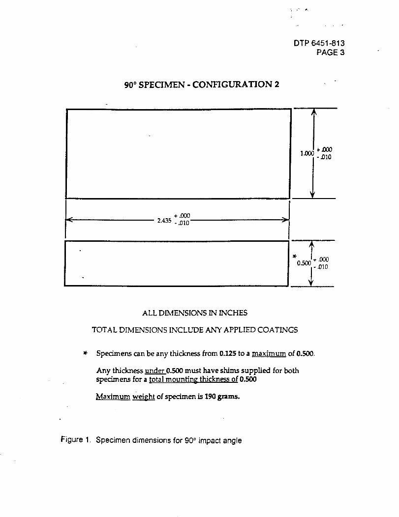
- o'- ,m,
DTP 6451-813
PAGE 3
90 ° SPECIMEN - CONFIGURATION 2
+._2.435 -.010
ALL DIMENSIONS IN INCHES
TOTAL DIMENSIONS INCLUDE ANY APPLIED COATINGS
Specimens can be any thickness from 0.125 to a maximum of 0.500.
Any thickness under 0.500 must have shims supplied for both
specimens for a total mounting thickness of 0.500
Maximum Weig_h). of specimen is 190 grams.
Figure 1. Specimen dimensions for 90 ° impact angle
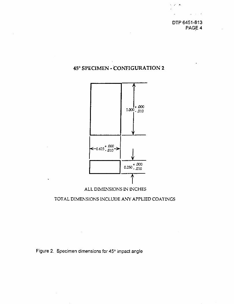
_. .' ,t.
DTP 6451-813
PAGE 4
45 ° SPECIMEN -:CONFIGURATION 2
l+ .O00
1"i" .010
+.000 _
.625..010 ---_ ,I,
+.0000_'250 - .010
ALL D_IFNSIONS IN INCHES
TOTAL DIMENSIONS INCLUDE ANY APPLIED COATINGS
Figure 2. Specimen dimensions for 45 ° impact angle
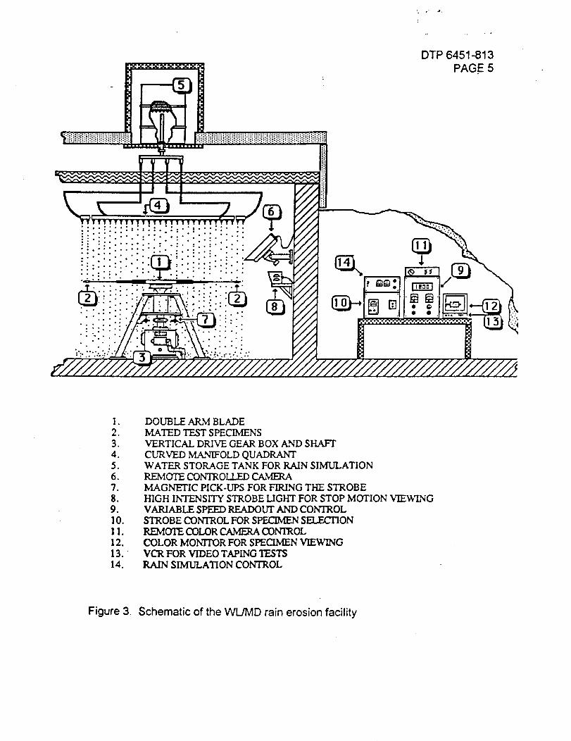
DTP 6451-813PAGE 5
• ...:...;t :t°:.°,........,:. °°
.
2.3.4.5.6.
7.8.
9.
I0.
II.
12.13.
14.
DOUBLE ARM BLADEMATED TEST SPECIMENS
VERTICAL DRIVE GEAR BOX AND SHAFT
CURVED MANIFOLD QUADRANTWATER STORAGE TANK FOR RAIN SIMULATIONREMOTE CONTROM.£D
MAGNETIC PICK-UPS FOR FIRING THE STROBE
HIGH INTENSITY STROBE LIGHT FOR STOP MOTION VIEWINGVARIABLE SPEED READOUT AND CONTROL
STROBE CONTROL FOR SPECIMEN SELECTIONREMCYIE COLOR CAMERA CONTROL
COLOR MONTrOR FOR SPECIMEN VIEWINGVCR FOR VIDEO TAPING TESTSRAIN SIMULATION CONTROL
Figure 3 Schematic of the WL/MD rain erosion facility
APPENDIX E
RAIN IMPACT, SINGLE DROP TESTING
DTP 6451-814PAGE 1
RAIN IMPACT (SINGLE DROP IMPACTS)DETAILED TEST PROCEDURE
NRA 8-12, SSTO TA-3
OBJECTIVE:
The objective of this test is to determine the effects of rain and/or ice impacts athigh velocities on TPS materials. Test impact velocities shall simulate thosecharacteristic of launch/landing.
SCOPE:
This document describes standard single-drop impact testing to beaccomplished on the 30 mm powder gun at the Advanced Technologies Divisionof General Research Corporation. Specific detailed test requirements arediscussed in the referencing document.
APPLICABLE DOCUMENTS:
"Capabilities Summary: Dynamic Behavior of Materials and Structures",February 1993, General Research Corporation, Santa Barbara.
TEST SPECIMEN:
The 30 mm powder gun used for single drop impact testing can currentlyaccommodate specimens up to 0.788 inches in diameter. A cylindrical "sabot" is
used to hold the sample and together they are accelerated through the gun'sbarrel. Normal incidence impacts are accomplished by utilizing a cylindricalspecimen with it's face perpendicular to it's axis. Off normal impacts can beachieved by changing the axis/face angle appropriately. Non-circular crosssection specimens of face dimensions less than 0.788 inches and a wide rangeof thicknesses can also be used. A detailed description of the test articles iscontained in the referencing document.
TEST SPECIMEN INSTRUMENTATION:
No specimen instrumentation is required.
TEST SETUP DESCRIPTION:
The General Research drop impact facility is shown schematically in Figure 1. Itconsists of a 30 mm barrel, a test chamber, and a recovery chamber. A powder
charge accelerates a sabot and sample down the barrel into the test chamber
DTP 6451-814PAGE 2
where it collides with a single water drop. After collision, the sabot isdecelerated to a stop in the recovery chamber. A laser optic system is used tocontrol timing and to measure sample velocity before impact. A high speedcamera is used to document drop or ice particle size and shape.
GENERAL REQUIREMENTS:
1. Test specimen must be received by the test facility at least seven days priorto the scheduled testing date.
2. Detailed descriptions of all test specimen must be delivered to the test facilitywith the test specimen.
PROCEDURE:
Test specimens shall be exposed to single drops at the impact angle andvelocity stipulated in the referencing document. All standard test procedures ofthe General Research Rain Erosion Facility shall be utilized during testing.
DATA REQUIREMENTS:
Specific damage and failure modes shall be recorded of all test specimens. Adetailed description of the visual state of the test specimen shall also bedocumented.
A photographic record shall be made of all specimens prior to and after eachimpact.
Mass loss of the specimen shall be recorded.
All data shall be delivered to the test requester and/or responsible test engineer.
TEST ARTICLE DISPOSITION:
Test articles shall be returned to the Rockwell responsible test engineer forretention.
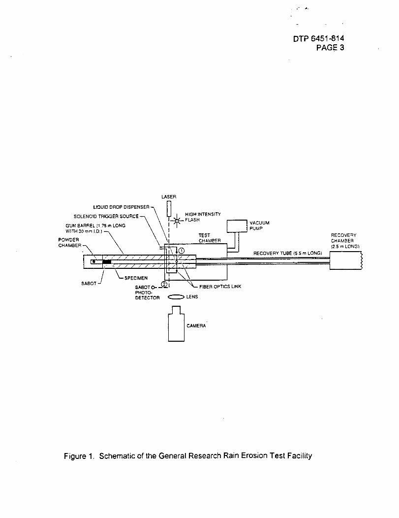
:. o-. ..
DTP 6451-814PAGE 3
LASER
LIQUID DROP DISPENSER _ II
SOLENOID TRIGGER SOURCE--.-, \ _. I. HIGH INTENSITY\\ I.--_ FLASH r-----"-I
GUN BARREL (1.75 m LONG \ \ Ifi" I I
POWDER _ \ \= CHAMBER I1
\ I=UI x ]. ." / / ," , // /Ih _,,jx,---'?_, l
J PECIME
ABOT SABOT O-" _(_..I _ FIBER OPTICS LINK
PHOTO-DETECTOR _ LENS
VACUUM
PUMP
RECOVERY TUBE (5.5 m LONG)
[_ CAMERA
RECOVERY
CHAMBER
(2.5 m LONG)
Figure 1. Schematic of the General Research Rain Erosion Test Facility

zm
imLL _l_
X illm Imr_z z
_11 rv
z
WIND/RAIN
DTP 6451-815
PAGE I
WIND/RAIN EXPOSURE
LABORATORIES AND TEST
DETAILED TEST PROCEDURE
NRA 8- 12, SSTO TA-3
WIND/RAIN
DTP 6451-815
PAGE 2
TABLE OF CONTENTS
1.0 INTRODUCTION ......................................................................
PURPOSE .................................................................................
3.0 APPLICABLE DOCUMENTS ..................................................
4.0 GENERAL REQUIREMENTS .................................................
4.1 TEST DATA ...............................................................
4.2 NOTICE OF TEST ........................................................
4.3 ANOMALY REPORTING .............................................
4.4 TEST REPORTING ......................................................
5.0 DETAILED TEST REQUIREMENTS .....................................
5.1 TEST EQUIPMENT AND INSTRUMENTATION ....
5.2 TEST MEASUREMENT TOL,ERANCE ......................
6.0 TEST PROCEDURES ...............................................................
6.1 TEST SET-UP VERIFICATION .............................
6.3 WIND/RAIN EXPOSURE ........................................
7.0 SPECIMEN DISPOSITION .................................................
2.0
3
3
3
3
3
3
3
4
4
4
5
5
5
7
8
WIND/RAINDTP 6451-815PAGE 3
1.0
2.0
3.0
4.0
INTRODUCTION
This document lists rain/wind requirements for SSTO lightweightdurable TPS, NRA 8-12.
PURPOSE
The purpose of the wind/rain testing is to expose SSTOconfigurations to representative launch pad/landing facilityconditions to verify durability in such adverse environments.
APPLICABLE DOCUMENTS
3.1 GOP3841-001 Space Systems Division, Laboratories and Test,General Operating Procedure for Rain/Wind Test Facility.
GENERALREQUIREMENTS
4.1 Test Data
4.1.1
4.1.2
4.1.3
4.1.4
4.1.5
Test data shall be recorded on data sheets approved by
the RTE, and retained in the test program permanent data
file.
All pertinent events, test conditions and test results
shall be recorded in Laboratory Notebooks.
Copies of the Laboratory Notebook pages shall be
transmitted to the Responsible Test Engineer (RTE) at
the conclusion of the tests.
All test information accumulated in the form of data
sheets, plots, or charts shall be transmitted to the RTE.
Photographs shall be taken at appropriate times to
document test setups and anomalies encountered.
4.2
4.3
Notice of Test
4.2.1 The RTE and Engineering Coordinator shall be notified at
least 24 hours prior to start of test.
Anomaly Reporting
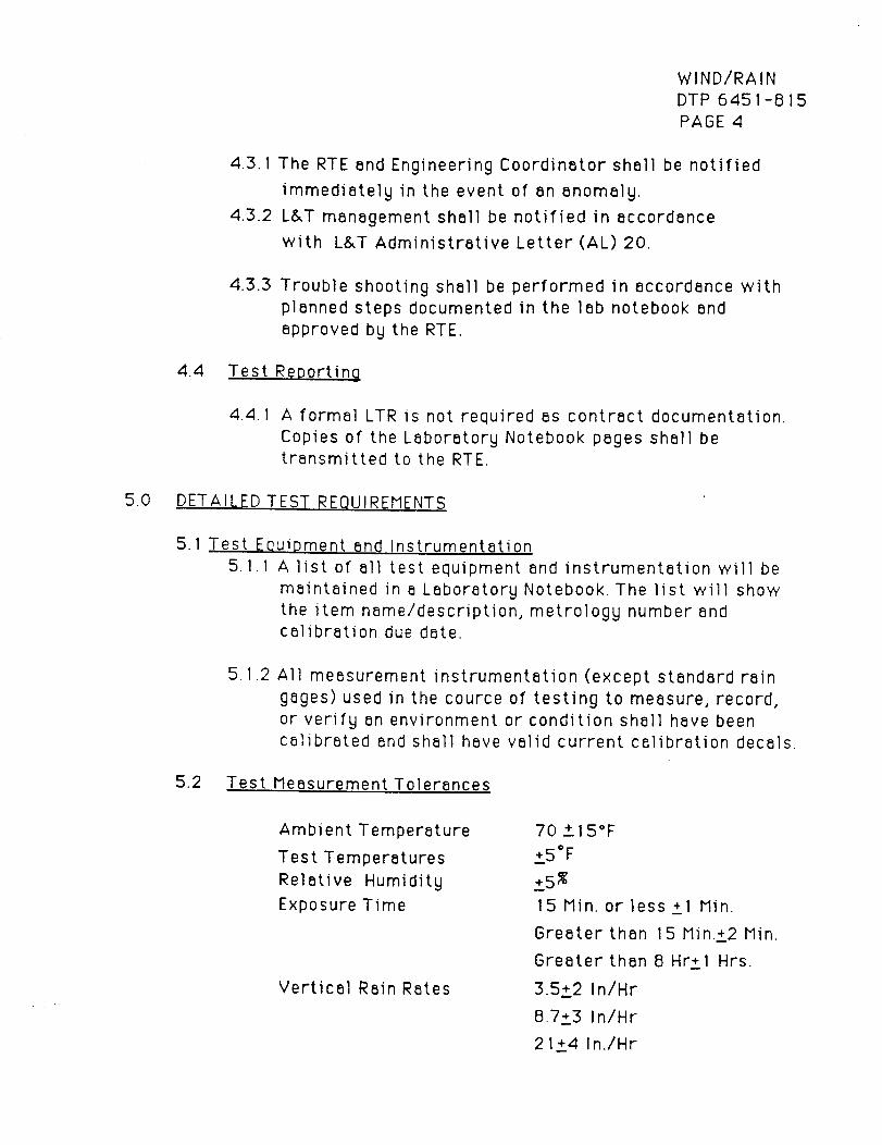
5.0
WIND/RAIN
DTP 6451-815
PAGE 4
4.3.1
4.3.2
The RTE and Engineering Coordinator shall be notified
immediately in the event of an anomaly.
L&T management shall be notified in accordance
with L&T Administrative Letter(AL) 20.
4.3.3 Trouble shooting shall be performed in accordance with
planned steps documented in the lab notebook and
approved by the RTE.
4.4 Test Reporting
4.4.1 A formal LTR is not required as contract documentation.
Copies of the Laboratory Notebook pages shall be
transmitted to the RTE.
DETAILED TEST REQUIREMENTS
5.1 Test Equipment end Instrumentation
5.1.1 A list of all test equipment and instrumentation will be
maintained in a Laboratory Notebook. The list will show
the item name/description, metrology number and
calibration due date.
5.1.2 All measurement instrumentation (except standard rain
gages) used in the cource of testing to measure, record,
or verify an environment or condition shall have been
calibrated and shall have valid current calibration decals.
5.2 Test Measurement Tolerances
Ambient Temperature
Test Temperatures
Relative Humidity
Exposure Time
Vertical Rain Rates
70 +_15°F
+_5°F
+_5%
15 Min. or less +_I Min.
Greater than 15 Min.+_2 Min.
Greater than 8 Hr+1 Hrs.
3.5+_2 InlHr
8.7+_3 InlHr
2 I_+4 In.IHr

WIND/RAINDTP 6451-815PAGE 5
Wind Rates 6.4+2 Knots50+5- 15 Knots
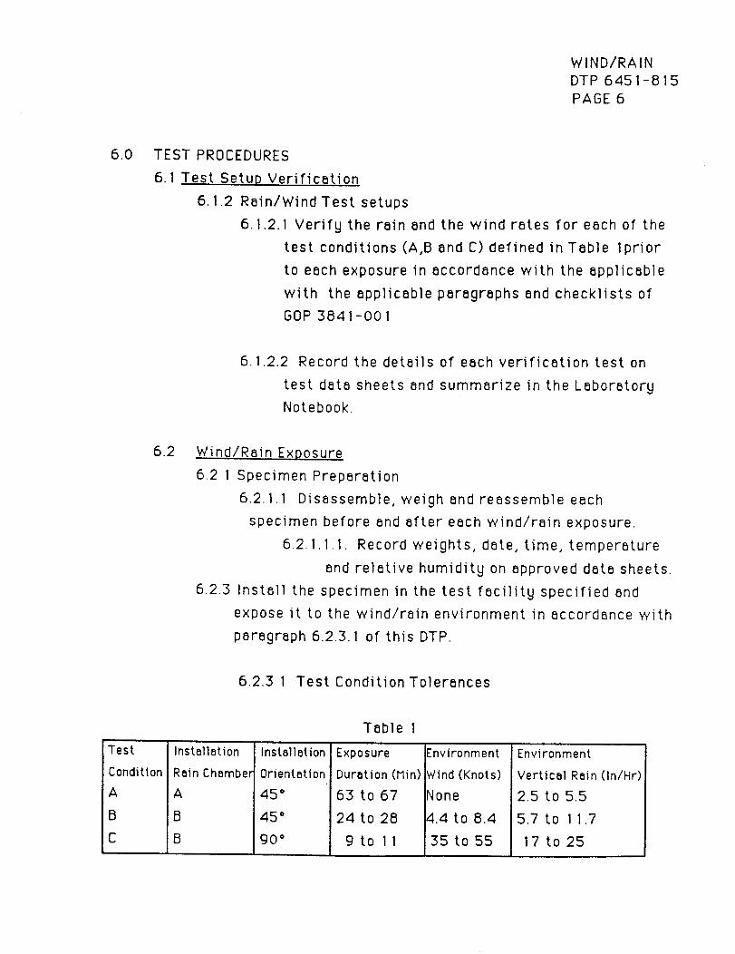
WIND/RAINDTP 6451-815PAGE 6
6.0 TEST PROCEDURES
6.1 Test Setup Verification
6.1.2 Rain/Wind Test setups
6.1.2.1 Verify the rain and the wind rates for each of the
test conditions (A,B and C) defined in Table /prior
to each exposure in accordance with the applicable
with the applicable paragraphs and checklists of
GOP 3841-001
6.1.2.2 Record the details of each verification test on
test data sheets and summarize in the Laboratory
Notebook.
6.2 Wind/Rain Exposure
6.2 1 Specimen Preparation
6.2.1.1 Disassemble, weigh and reassemble each
specimen before and after each wind/rain exposure.
6.2.1.1 .I. Record weights, date, time, temperature
and relative humidity on approved data sheets.
6.2.3 Install the specimen in the test facility specified and
expose it to the wind/rain environment in accordance with
paragraph 6.2.3.1 of this DTP.
6.2.3 1 Test Condition Tolerances
Test
Condition
A
B
C
Installation
Rain Chamber
A
B
B
Installation
Orientatior
45 °
45 °
90 °
Table I
Exposure
Duration (Min)
63 to 67
24 to 28
9to 11
£nvironment
_tind (Knots)
klone
4.4 to 8.4
35 to 55
Environment
Vertical Rain (InlHr)
2.5 to 5.5
5.7 to 11.7
17 to 25
WIND/RAINDTP 6451-815PAGE 7
6.2.3.2 Record specimen number, average wind and rain
rate calibration data, test data, test start time,
ambient air temperature, system water flow rate,
the nozzle pressures in the Laboratory Notebook for
each environment exposure.
7.0 SPECIMENDISPOSITION
Transfer the test specimens to the RTE or his representative for
disposition.

APPENDIX G
SALT SPRAY TESTING
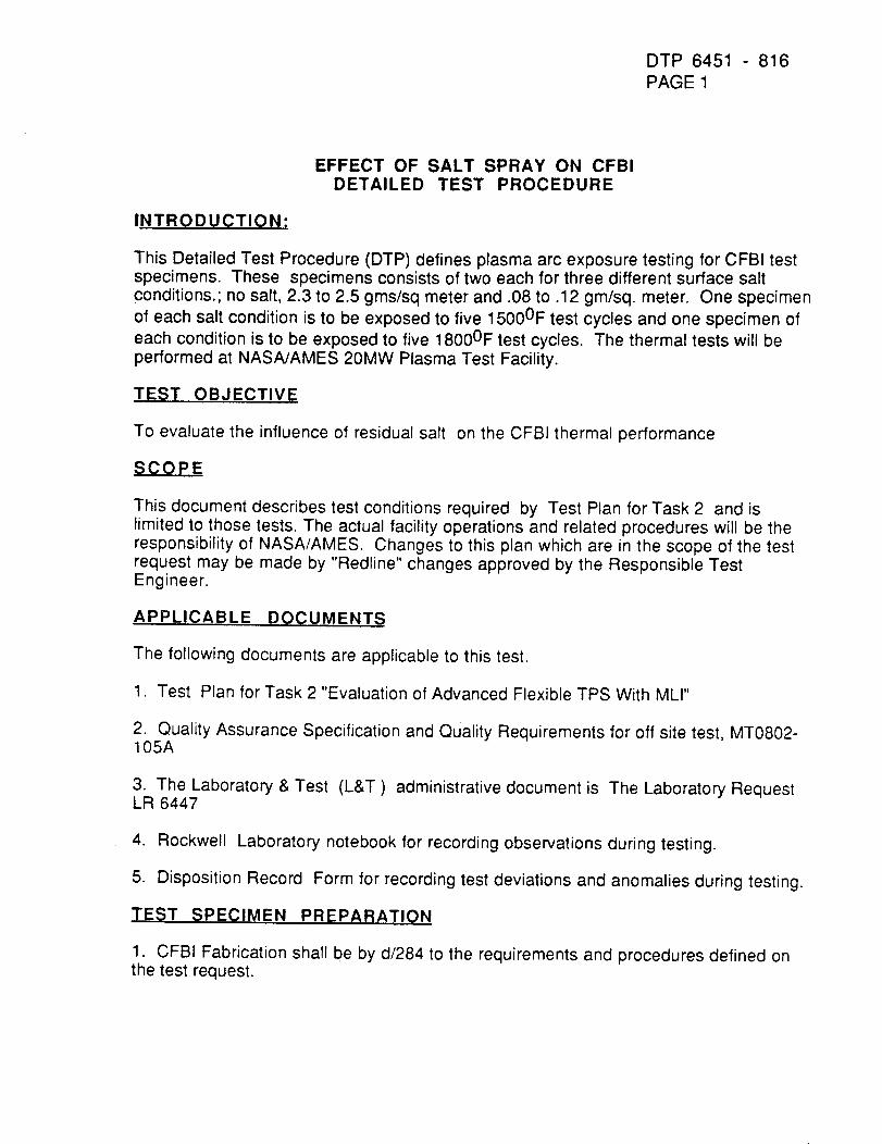
DTP 6451 - 816
PAGE 1
EFFECT OF SALT SPRAY ON CFBIDETAILED TEST PROCEDURE
INTRODUCTION:
This Detailed Test Procedure (DTP) defines plasma arc exposure testing for CFBI testspecimens. These specimens consists of two each for three different surface saltconditions.; no salt, 2.3 to 2.5 gms/sq meter and .08 to .12 gm/sq, meter. One specimen
of each salt condition is to be exposed to five 15000F test cycles and one specimen of
each condition is to be exposed to five 18000F test cycles. The thermal tests will beperformed at NASA/AMES 20MW Plasma Test Facility.
TEST OBJECTIVE
To evaluate the influence of residual salt on the CFBI thermal performance
SCOPE
This document describes test conditions required by Test Plan for Task 2 and islimited to those tests. The actual facility operations and related procedures will be theresponsibility of NASA/AMES. Changes to this plan which are in the scope of the testrequest may be made by "Redline" changes approved by the Responsible TestEngineer.
APPLICABLE DOCUMENTR
The following documents are applicable to this test.
1. Test Plan for Task 2 "Evaluation of Advanced Flexible TPS With MLI"
2. Quality Assurance Specification and Quality Requirements for off site test, MT0802-105A
3. The Laboratory & Test (L&T) administrative document is The Laboratory RequestLR 6447
4. Rockwell Laboratory notebook for recording observations during testing.
5. Disposition Record Form for recording test deviations and anomalies during testing.
TEST SPECIMEN PREPARATION
1. CFBI Fabrication shall be by d/284 to the requirements and procedures defined onthe test request.

DTP 6451 - 816PAGE 3
2. Notice of Test - The RTE shall be notified in advance of any scheduled test.
3. Photographic Coverage - Color photographs will be taken of the test panels whenany visual variance from initial condition is noticed.
4. Inspection - A general visual inspection of the test panel and fixture shall be madeprior to the start of the test. A complete visual inspection along with color photographsshall be made after each test in order to determine any damage that might occur.Flexibility of the blanket shall be determined after each plasma flow exposure of the lastspecimen to determine if blankets stiffened. One method of blanket stiffness
determination will be to flex the Outer Mold Line (OML) with a finger.
5. Report - NASA/Ames shall publish a test agency report at the completion of the testprogram while the RTE shall publish an interpretative Laboratory Test Report (LTR).
TEST PROCEDURE
NASA/Ames shall provide the facility apparatus, setup, data acquisition, data reductionand facility detailed test procedure for plasma exposure.
Test Conditions - The OML surface of the blanket specimens shall be exposed to aheating environment per Table 1 resulting in the LRSI control surface temperatureshown in figure 5 at minimum attainable chamber pressure. Maximum soak and
temperature on the aluminum substrate backface shall be limited to 3500F by use of acoldplate (figure 5) or other technique chosen by the test agency and approved by theRTE. An optical pyrometer shall be used to monitor the surface temperature of the
blankets (approximately 2 microns narrow band sensor for best results). The pyrometerdata acquisition shall be non-interference with the plasma test exposures.
Routine test procedures shall be the responsibility of the testing agency (NASA/Ames).
Pre-test Calibration - The test environment of NASA/Ames 20 MW plasma arc facilityshall be demonstrated by a series of runs using an LRSI tile calibration modelinstrumented with 20 type "R '° 30 gauge thermocouples. See Figure 6 for a sketch ofthe LRSI hot wall calibration model. This model is made from a 14.5" x17.5x 1/8" thick
aluminum plate onto which are bonded four instrumented LRSI tiles leaving a nominaXone inch of aluminum exposed on all edges.
Test specimens shall be visually inspected before insertion into the test chamber.
After calibrations are made each bonded blanket test specimen shall be placed in thetest fixture holder and exposed thermally to plasma flow following the profile of figure 5.
Prior to starting a test run the temperature of the test article shall be below 1000F and
the test instrumentation shall be checked for continuity.
Prior to each test run and after each test run the test specimen shall be examined forflexibility. NASA/Ames is responsible is responsible for all data acquisition.
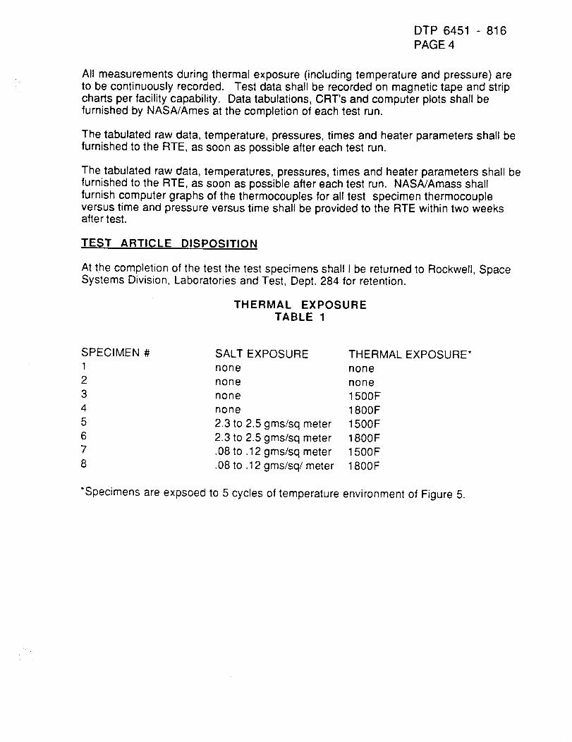
DTP 6451 816PAGE 4
All measurements during thermal exposure (including temperature and pressure) areto be continuously recorded. Test data shall be recorded on magnetic tape and stripcharts per facility capability. Data tabulations, CRT's and computer plots shall befurnished by NASA/Ames at the completion of each test run.
The tabulated raw data, temperature, pressures, times and heater parameters shall befurnished to the RTE, as soon as possible after each test run.
The tabulated raw data, temperatures, pressures, times and heater parameters shall befurnished to the RTE, as soon as possible after each test run. NASA/Amass shallfurnish computer graphs of the thermocouples for all test specimen thermocoupleversus time and pressure versus time shall be provided to the RTE within two weeksafter test.
TEST ARTICLE DISPOSITION
At the completion of the test the test specimens shall I be returned to Rockwell, SpaceSystems Division, Laboratories and Test, Dept. 284 for retention.
THERMAL EXPOSURETABLE 1
SPECIMEN # SALT EXPOSURE THERMAL EXPOSURE*
1 none none
2 none none
3 none 1500F
4 none 1800F
5 2.3 to 2.5 gms/sq meter 1500F
6 2.3 to 2.5 gms/sq meter 1800F
7 .08 to .12 gms/sq meter 1500F
8 .08 to .12 gms/sq/meter 1800F
*Specimens are expsoed to 5 cycles of temperature environment of Figure 5.

_U0
0 _C "UCO m-4 ZI m
C'_ x
I--ImcI}
z
DTP 6451-817PAGE 1
THERMAL PROTECTION SYSTEM
PROGRESSIVE WAVE TUBE VIBROACOUSTIC
DETAILED TEST PROCEDURE
NRA 8-12, SSTO TA-3
TESTING
DYNAMICS TEST ENGINEER: JIM McGEE
CONTENTS
DTP 6451-817
PAGE 2
1.0. INTRODUCTION AND TEST SPECIMEN DESCRIPTION
2.O. SCOPE
3.0. APPLICABLE DOCUMENTS
4.0. GENERAL REQUIREMENTS
5.0. DETAILED REQUIREMENTS
6.0. PROCEDURES
6.1. TEST SETUP PROCEDURES
6.1.1. MECHANICAL SETUP
6.1.2. EXCITATION, INSTRUMENTATION, AND DATA SETUP6.2. TEST READINESS REVIEW
6.3. TEST PROCEDURE NOTES
6.3.1. EVENT IDENTIFICATION
6.3.2. TEST PERSONNEL
6.3.3. SYSTEM EQUALIZATION/PRELIMINARY TEST RUNS
6.3.4. EMERGENCY SHUTDOWN PROCEDURE
6.4. TEST RUN PROCEDURES6.5. TEST SETUP TEARDOWN
6.6. TEST SPECIMEN DISPOSITION
7.0. DATA REQUIREMENTS
8.0. TEST EQUIPMENT
9.0. FIGURES AND TABLES
APPENDICES
A.I. EMERGENCY SHUTDOWN PROCEDURE
1.0. INTRODUOTION AND TEST SPECIMEN DESCRIPTION.
1.1. INTRODUCTION.
DTP 6451-817
PAGE 3
This procedure details the steps for vibroacoustic testing
of lightweight durable thermal protection system materialsfor the SSTO.
1.2. SPECIMEN.
The test specimens will be those specimens tested under
NRA8-12, Lightweight Durable Thermal Protection System(TA-3).
1.3. TEST DESCRIPTION
1. Task 2, ID 5h: Flexible TPS btanket/MLI composite in aprogressive wave tube acoustic environment at 160 dBSPL.
,
.
Task 4, ID 6f: Direct bond AETB tiles to graphitecomposite substrate in a progressive wave tubeacoustic environment at 160 dB SPL.
Task 4, ID 6p: Ceramic matrix composite tile cover
attached to AETB substrate in a progressive wave tubeacoustic environment at 160 dB SPL.
4. Other tasks as required.
2.0. SCOPE.
2.1. PURPOSE
The purpose of this testing will be to evaluate advanced
TPS components for the SSTO, subjected to vibroacousticenvironments.
2.2. OBJECTIVES
° Demonstrate Flexible TPS/MLI composite blanketperformance in a vibroacoustic environment.
DTP 6451-817PAGE 4
,
.
4.
Determine performance of direct-bond tiles subjected tovibroacoustic loads.
Evaluate CMC covers subjected to vibroacoustic loads.
Other vibroacoustic testing as required.
3.0. APPLICABLE DO01JMENT£.
The following Rockwell SSD specifications, drawings, and
documents, are applicable to the performance of the tests:
. Advanced Structures and TPS Technologies (NRA8-12)
Test Plans for TA-3, especially Task 2 and Task 4Plans;
. Rockwell/SSD Safety Operating Manual- Pub. 2548-R,Rev. 1991 ;
3. Laboratories, Test, and Material Sciences Drawings TBD;
4.0. GENERAL REQUIREMENTS.
4.1. SPECIMEN LOG
A Laboratory Notebook shall be kept to record all moves,
adjustments, setup information for excitation systems,instrumentation systems, specimen attachments, and other
subsystems, setup changes, and test runs. Pertinentinformation regarding data shall also be recorded.
4.2. TEST DATA
All notes necessary for proper understanding of the test
data shall be recorded in the Laboratory Notebook. Testdata shall be in the form of third-octave plots of sound
pressure level versus frequency for microphone data
channels, and narrow-band plots of acceleration power
spectral density versus frequency for accelerometers.Plots of acceleration versus frequency for accelerometers
DTP 6451-817PAGE 5
will also be available for swept sine vibration tests. Straingage data shall be in a form comparable to accelerometerdata, using appropriate engineering units. Time domainplots will also be available upon request for all data.
4.3. NOTICE OF TEST
The Engineering Test Requester, or an assignedrepresentative, shall be notified prior to the start of eachtest run, with sufficient advance notice to be in attendance.
4.4. FAILURE AND INCIDENT REPORTING
In the event that a specimen failure or incident occurs,after immediately securing the area, the test personnelshall notify the test requester and all pertinent programand functional management personnel.
4.5. TEST REPORTING
Upon completion of all tests, a White Test Report and copiesof all Laboratory Notebook pages shall be prepared andissued to the test requester.
4.6. DISPOSITION OF TEST HARDWARE
Upon completion of all tests, the test specimens shall bereturned to the Test Requester for disposition.
5.0. DETAILED REQUIREMENTS.
5.1. EQUIPMENT CALIBRATION
All measurement equipment used on the test shall be
calibrated with traceability to the National Institute of
Standards and Technology (NIST). Date tags or decals shall
be attached to applicable equipment or their storage boxes,which indicate that such calibration is current. Deviations
will be approved by the Engineering Test Requesters.Verification of instrument calibrations and due dates shall
be performed prior to test. Equipment calibrationinformation shall be recorded in the laboratory notebook.
DTP 6451-817PAGE 6
5.2. TOLERANCES
Required tolerances of test conditions and data will bedetermined and approved by the Engineering TestRequesters.
5.3. QUALIFICATION CRITERIA
NRA8-12 TA-3 tests are engineering development tests, andtherefore qualification criteria is not applicable.
5.4. TEST SEQUENCE
In lieu of requests by the Engineering Test Requester, thesequence of tests will be determined by the ResponsibleTest Engineer.
6.0. PROCEDURES.
CAUTION: ALL NECESSARY MEASURES SHALL BE
TAKEN TO PROTECT THE TEST SPECIMEN
FROM ANY DAMAGE WHILE MOVING IT,MOVING OTHER HARDWARE AROUND THE TEST
SPECIMEN, MOUNTING THE TEST SPECIMEN,OR ATTACHING INSTRUMENTATION TO THE
TEST SPECIMEN. ACCESS TO THE TEST
SPECIMEN SHALL GENERALLY BE LIMITED TOTEST PERSONNEL ONLY.
6.1. TEST SETUP PROCEDURES
NOTE: Refer to figure 1 for a flow diagram of the Acoustic Test
Facility, including plumbing, excitation, andinstrumentation systems.
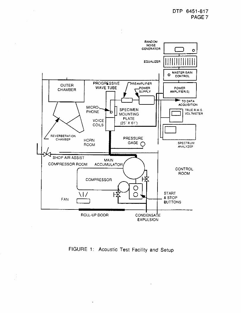
DTP 6451-817PAGE 7
L
, I
OUTER I
CHAMBER
_ MICRO- ,
PHONE--__ ]VOICECOILS
PROGRESSIVE _-PREAMPLIFIER
WAVE TU__BE / __.POWER
SPECIMENMOUNTING
PLATE
(25"' X 61")
Z REVERBERATIONCHAMBER HORN
ROOM
_SIST
COMPRESSOR ROOM
f PRESSURE
MAINACCUMULATOR
FAN
COMPRESSOR
\1/
ROLL-UP DOOR
RANDOM
NOISE !GENERATOR 0
I
IIJJllllllJlliZI
MASTER GAIN0 CONTROL
I
,_ POWERAMPLIFIER(S)
r TO DATA
ACOUISITION
,q_---_ TRUE RM.S
VOLTMETER
fSPECTRUMANALYZER
CONTROLROOM
START__ & STOP
BUTTONS
CONDENSA EEXPULSION
FIGURE 1" Acoustic Test Facility and Setup
DTP 6451-817PAGE 8
WARNING: WHEN WORKING ABOVE OR AROUND THE TEST
SPECIMEN, OR IN AN AREA WHERE OTHER
PERSONNEL MAY BE BELOW, ANY LOOSEEQUIPMENT THAT MAY BE DROPPED SHALL BE
TETHERED, TO PREVENT DAMAGE TO THE
SPECIMEN OR INJURY.
6.1.1. INSTRUMENTATION SETUP AND CHECKOUT
6.1.1.1. Select appropriate microphones for the sound to be
measured. Hook up the microphones to the preamplifiers.
6.1.1.2. Connect the preamplifiers to the microphone power supplies.Connect the output of the microphone power supplies to the
appropriate data patches. Turn on the microphone power
supplies an adequate period of time for warming up prior totaking any measurements, including calibrations.
6.1.1.3. Connect the data patches or microphone power supplies to aspectrum analyzer or a true R.M.S. voltmeter for
measurement of the channel outputs.
6.1.1.4. Insert each microphone to be calibrated into a calibrator
piston phone. Turn on the piston phone. Read the overall
sound pressure level and, if using a spectrum analyzer, the
level at the band of the calibrator piston phone. If using a
calibrator piston phone with different output levels, set thecalibrator piston phone at different levels to determine
linearity. If linearity is not accurate, note the results ofthe linearity check in the lab notebook, and use the
calibrator piston phone setting closest to the overall soundpressure level at which the test will be run. Determine the
reference voltage corresponding to a reference soundpressure level. This will be known as the "calibration
voltage."
After calibration voltages are determined, install the
microphones at their appropriate location in the progressivewave tube or reverberation chamber.
6.1.1.5.
6.1.2. CHAMBER AND AREA SETUP AND CHECKOUT
6.1.2.1. Verify that the voice coil box is attached to the appropriateacoustic test chamber (progressive wave tube or
reverberation chamber).
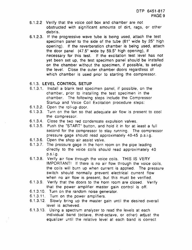
DTP 6451-817PAGE 9
6.1.2.2
6.1.2.3.
Verify that the voice coil box and chamber are notobstructed with significant amounts of dirt, rags, or otherdebris.
If the progressive wave tube is being used, attach the testspecimen panel to the side of the tube (61" wide by 25" high
opening). If the reverberation chamber is being used, attach
the door panel (47.5" wide by 59.5" high opening), if
necessary for this test. If the excitation test level has not
yet been set up, the test specimen panel should be installed
on the chamber without the specimen, if possible, to setupthe level. Close the outer chamber doors regardless of
which chamber is used prior to starting the compressor.
6.1.3. LEVEL CONTROL SETUP
6.1.3.1. Install a blank test specimen panel, if possible, on the
chamber, prior to installing the test specimen in the
chamber. The following steps include the Compressor
Startup and Voice Coil Excitation procedure steps:6.1.3.2. Open the roll-up door.
6.1.3.3. Turn on the fan so that adequate air flow is present to cool
the compressor.
6.1.3.4. Close the two red condensate expulsion valves.6.1.3.5. Push the "START" button, and hold it in for at least a full
second for the compressor to stay running. The compressor
pressure gage should read approximately 40-45 p.s.i.g.6.1.3.6. Open the shop air assist valve.
6.1.3.7. The pressure gage in the horn room on the pipe leading
directly to the voice coils should read approximately 40p.s.i.g.
6.1.3.8. Verify air flow through the voice coils. THIS IS VERYIMPORTANT! If there is no air flow through the voice coils,
the coils will burn up when current is applied. The pressure
switch should normally prevent electrical current flow
when no air flow is present, but this must be verified.
6.1.3.9. Verify that the doors to the horn room are closed. Verify
that the power amplifier master gain control is off.6.1.3.10. Turn on the random noise generator.
6.1.3.11. Turn on the power amplifiers.
6.1.3.12. Slowly bring up the master gain until the desired overalllevel is achieved.
6.1.3.13. Using a spectrum analyzer to read the levels at each
individual band (octave, third-octave, or other) adjust theequalizer until the relative level at each band is correct
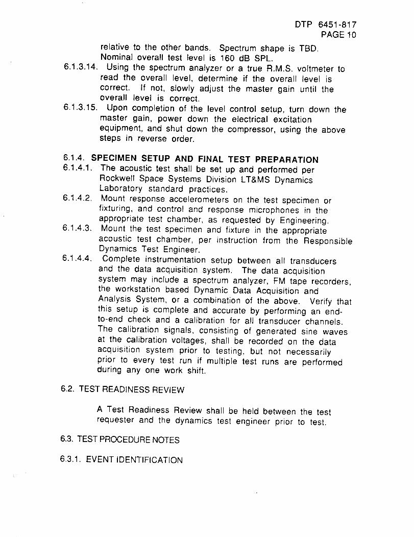
6.1.3.14.
6.1.3.15.
DTP 6451-817PAGE 10
relative to the other bands. Spectrum shape is TBD.Nominal overall test level is 160 dB SPL.
Using the spectrum analyzer or a true R.M.S. voltmeter toread the overall level, determine if the overall level iscorrect. If not, slowly adjust the master gain until theoverall level is correct.
Upon completion of the level control setup, turn down themaster gain, power down the electrical excitationequipment, and shut down the compressor, using the abovesteps in reverse order.
6.1.4. SPECIMEN SETUP AND FINAL TEST PREPARATION
6.1.4.1. The acoustic test shall be set up and performed per
Rockwell Space Systems Division LT&MS DynamicsLaboratory standard practices.
6.1.4.2. Mount response accelerometers on the test specimen or
fixturing, and control and response microphones in the
appropriate test chamber, as requested by Engineering.6.1.4.3. Mount the test specimen and fixture in the appropriate
acoustic test chamber, per instruction from the ResponsibleDynamics Test Engineer.
6.1.4.4. Complete instrumentation setup between all transducers
and the data acquisition system. The data acquisition
system may include a spectrum analyzer, FM tape recorders,the workstation based Dynamic Data Acquisition and
Analysis System, or a combination of the above. Verify thatthis setup is complete and accurate by performing an end-to-end check and a calibration for all transducer channels.
The calibration signals, consisting of generated sine waves
at the calibration voltages, shall be recorded on the data
acquisition system prior to testing, but not necessarily
prior to every test run if multiple test runs are performedduring any one work shift.
6.2. TEST READINESS REVIEW
A Test Readiness Review shall be held between the test
requester and the dynamics test engineer prior to test.
6.3. TEST PROCEDURE NOTES
6.3.1. EVENT IDENTIFICATION
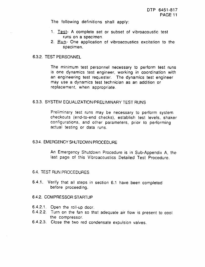
DTP 6451-817PAGE 11
The following definitions shall apply:
1. _- A complete set or subset of vibroacoustic testruns on a specimen.
2. Run- One application of vibroacoustics excitation to the
specimen.
6.3.2. TEST PERSONNEL
The minimum test personnel necessary to perform test runs
is one dynamics test engineer, working in coordination with
an engineering test requester. The dynamics test engineer
may use a dynamics test technician as an addition or
replacement, when appropriate.
6.3.3. SYSTEM EQUALIZATION/PRELIMINARY TEST RUNS
Preliminary test runs may be necessary to perform system
checkouts (end-to-end checks), establish test levels, shaker
configurations, and other parameters, prior to performingactual testing or data runs.
6.3.4. EMERGENCY SHUTDOWN PROCEDURE
An Emergency Shutdown Procedure is in Sub-Appendix A, thelast page of this Vibroacoustics Detailed Test Procedure.
6.4. TEST RUN PROCEDURES
6.4.1. Verify that all steps in section 6.1 have been completedbefore proceeding.
6.4.2. COMPRESSOR STARTUP
6.4.2.3.
Open the roll-up door.
Turn on the fan so that adequate air flow is present to coolthe compressor.
Close the two red condensate expulsion valves.
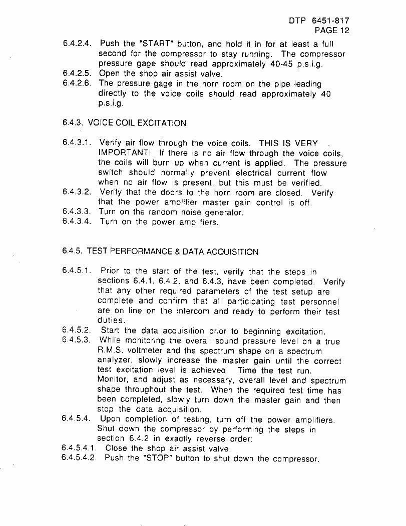
DTP 6451-817PAGE 12
6.4.2.4. Push the "START" button, and hold it in for at least a fullsecond for the compressor to stay running. The compressorpressure gage should read approximately 40-45 p.s.i.g.
6.4.2.5. Open the shop air assist valve.6.4.2.6. The pressure gage in the horn room on the pipe leading
directly to the voice coils should read approximately 40p.s.i.g.
6.4.3. VOICE COIL EXCITATION
6.4.3.1.
6.4.3.2.
6.4.3.3.6.4.3.4.
Verify air flow through the voice coils. THIS IS VERYIMPORTANT! If there is no air flow through the voice coils,the coils will burn up when current is applied. The pressureswitch should normally prevent electrical current flowwhen no air flow is present, but this must be verified.Verify that the doors to the horn room are closed. Verifythat the power amplifier master gain control is off.Turn on the random noise generator.Turn on the power amplifiers.
6.4.5. TEST PERFORMANCE & DATA ACQUISITION
6.4.5.1.
6.4.5.4.
Prior to the start of the test, verify that the steps insections 6.4.1, 6.4.2, and 6.4.3, have been completed. Verifythat any other required parameters of the test setup arecomplete and confirm that all participating test personnelare on line on the intercom and ready to perform their testduties.
Start the data acquisition prior to beginning excitation.While monitoring the overall sound pressure level on a trueR.M.S. voltmeter and the spectrum shape on a spectrumanalyzer, slowly increase the master gain until the correcttest excitation level is achieved. Time the test run.Monitor, and adjust as necessary, overall level and spectrumshape throughout the test. When the required test time hasbeen completed, slowly turn down the master gain and thenstop the data acquisition.Upon completion of testing, turn off the power amplifie, rs.
Shut clown the compressor by performing the steps insection 6.4.2 in exactly reverse order:
Close the shop air assist valve.Push the "STOP" button to shut down the compressor.
6.4.5.4.3.6.4.5.4.4.6.4.5.4.5.
DTP 6451-817PAGE 13
Open the two red condensate expulsion valves.Turn off the fan.Close the roll-up door.
6.5. TEST SETUP TEARDOWN
After completion of testing, all instrumentation and othertest equipment shall be removed from the specimen, unlessotherwise agreed to by the engineering _test requester andthe test engineer. The test specimen shall be removed fromthe acoustic chamber.
6.6. TEST SPECIMEN DISPOSITION
After completion of testing and setup teardown, transferthe test specimen to the test requester or designatedrepresentative for disposition.
7.0. DATA REQUIREMENTS.
7.1. HARD COPIES
Hard copies of data plots, per paragraph 4.2, shall be madeavailable to the test requester. Sample data sheets are
shown in Figure 2 for microphone data and Figure 3 foraccelerometer data.
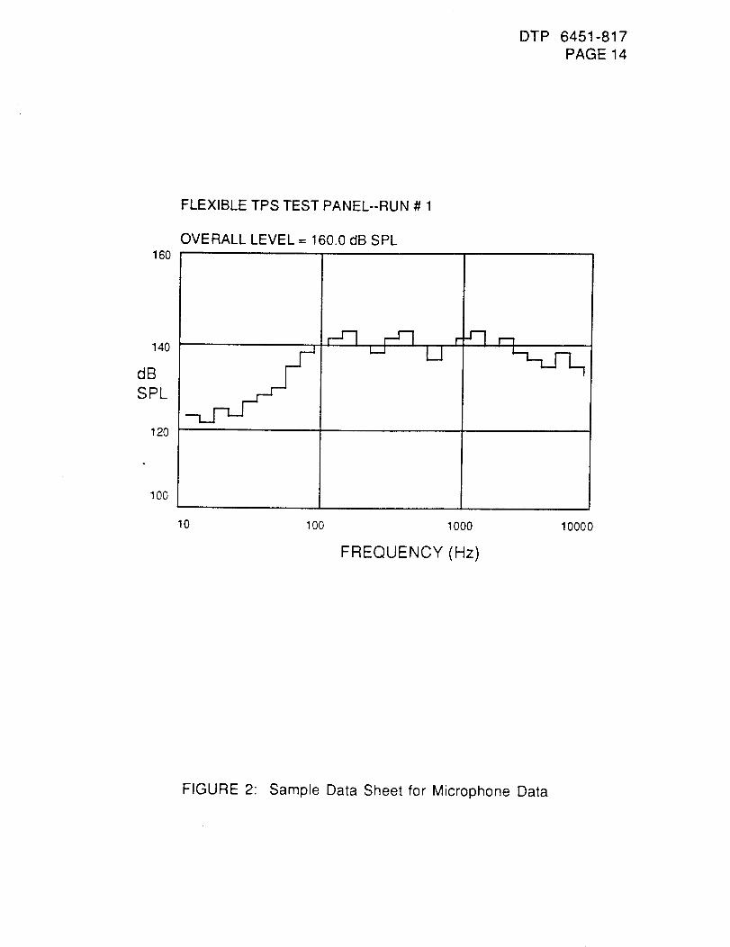
DTP 6451-817PAGE 14
160
140
dB
SPL
120
100
FLEXIBLE TPS TEST PANEL--RUN # 1
OVERALL LEVEL = 160.0 dB SPL
r 'qL.J
10 1O0 1000
FREQUENCY (Hz)
1000 0
FIGURE 2 Sample Data Sheet for Microphone Data
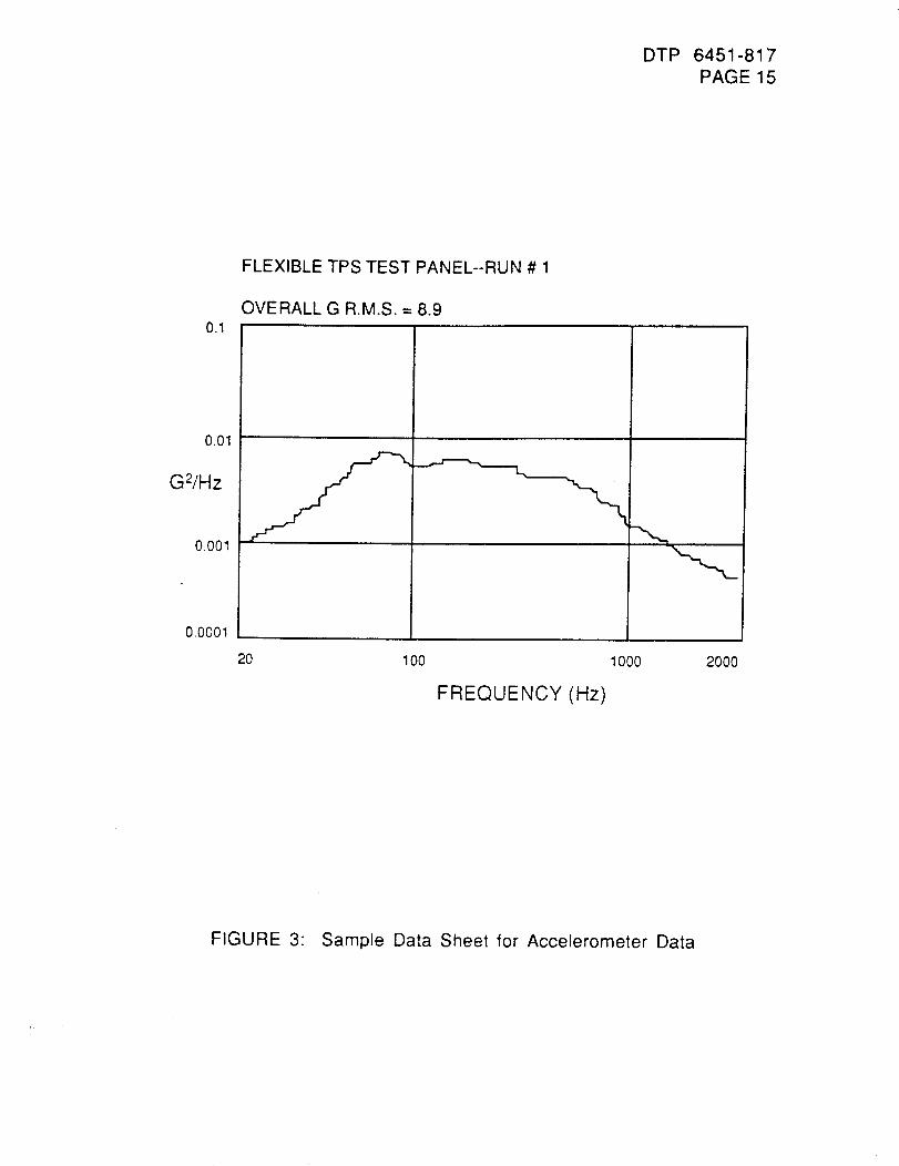
DTP 6451-817PAGE 15
0.1
0.01
G2/Hz
0.001
0.0001
FLEXIBLE TPS TEST PANEL--RUN # 1
OVERALL G R.M.S. = 8.9
20 100 1000
FREQUENCY (Hz)
2000
FIGURE 3: Sample Data Sheet for Accelerometer Data
DTP 6451-817PAGE 16
7.2. DATA FILES
All data for all test runs shall be stored on magnetic mediafor the duration of the program, or until the test requesterconcurs that the data can be disposed of.
7.3. TEST REPORT
A White Test Report and copies of all Laboratory Notebookpages shall be prepared and issued to the test requester.
8.0. TEST EQUIPMENT.
The following test equipment will be utilized for the test:
8.1. MECHANICAL SYSTEM.
Progressive wave tube acoustic chamberTest specimen panelAttachment hardwareVoice coils
Compressor and associated plumbingIndication pressure gaugesFan
Shop air assist valve
8.2. ELECTRICAL EXCITATION SYSTEM
Random noise generatorEqualizer
Master gain controlPower amplifiers
8.3. INSTRUMENTATION
Microphone
Microphone preamplifier
Microphone power supplyTrue R.M.S. voltmeter
Spectrum analyzerAccelerometers

Charge amplifiersOther sensors (optional)Other signal conditioning (optional)F.M. tape recorder (optional)Digital data acquisition system (optional)
DTP 6451-817PAGE 17
DTP 6451-817PAGE 18
SUB-APPENDIXA: EMERGENCYPROCEDURES
A.1. EMERGENCYPROCEDURES
° Any member of the test team noting an abnormal
condition shall immediately notify the Dynamics Test
Engineer or his designated representative, hereinafterreferred to as the Test Conductor.
° The Test Conductor has the sole responsibility to order
the excitation removed during test.
A.2. EMERGENCY SHUTDOWN PROCEDURE
° Upon becoming aware of an abnormal test condition, theTest Conductor shall immediately make a judgment asto whether the excitation level should be reduced orshut down.
*** NOTE ***
IF THE TEST CONDUCTOR AND THEENGINEERING TEST REQUESTER CONCUR
THAT THE ABNORMAL TEST CONDITIONS
EXPERIENCED ARE NOT DETRIMENTAL TO
THE TEST SPECIMEN AND THAT DATA
ACQUISITION AT THAT LEVEL OF
EXCITATION WOULD BE ADVANTAGEOUS TO
THE TEST OBJECTIVES, THE ABNORMALTEST CONDITIONS MAY BE IGNORED BY THE
TEST CONDUCTOR AND DATA ACQUISITIONMAY PROCEED.
, At any time an emergency exists that requiresimmediate shutdown, the Test Conductor shall issue
an order for the nearest test personnel to reduce themaster gain.
APPENDIX I
VIBRATION TESTING

DTP
MECHANICAL VIBRATION TESTING
DETAILED TEST PROCEDURE
NRA 8-12, SSTO TA-3
6451-818PAGE 1
DYNAMICS TEST ENGINEER: JIM McGEE

CONTENTS
DTP 6451-81 8
PAGE 2
1.0. INTRODUCTION AND TEST SPECIMEN DESCRIPTION
2.0. SCOPE
3.0. APPLICABLE DOCUMENTS
4.0. GENERAL REQUIREMENTS
5.0. DETAILED REQUIREMENTS
6.0. PROCEDURES
6.1. TEST SETUP PROCEDURES6.1.1. MECHANICAL SETUP
6.1.2. EXCITATION, INSTRUMENTATION, AND DATA SETUP6.2. TEST READINESS REVIEW
6.3. TEST PROCEDURE NOTES
6.3.1. EVENT IDENTIFICATION6.3.2. TEST PERSONNEL
6.3.3. SYSTEM EQUALIZATION/PRELIMINARY TEST RUNS6.3.4. EMERGENCY SHUTDOWN PROCEDURE
6.4. TEST RUN PROCEDURES
6.5. TEST SETUP TEARDOWN
6.6. TEST SPECIMEN DISPOSITION
7.0. DATA REQUIREMENTS
8.0. TEST EQUIPMENT
9.0. FIGURES AND TABLES
APPENDICES
A.1. EMERGENCY SHUTDOWN PROCEDURE
1.0. INTRODUCTION AND TEST SPECIMEN DESCRIPTION
1.1. INTRODUCTION.
DTP 6451-818
PAGE 3
This procedure details the steps for mechanical vibration
testing of lightweight durable thermal protection systemmaterials for the SSTO.
1.2. SPECIMEN.
The test specimens will be those specimens tested under
NRA8-12, Lightweight Durable Thermal Protection System(TA-3).
1.3. TEST DESCRIPTION
. Task 2, ID 5h: Flexible TPS blanket/MLI composite in amechanical vibration/deflection environment at 0.067
g2/Hz, or TBD.
2. Other tasks as required.
2.0. SCOPE.
2.1. PURPOSE
The purpose of this testing will be to evaluate advanced
TPS components for the SSTO, subjected to mechanicalvibration/deflection environments.
2.2. OBJECTIVES
. Demonstrate Flexible TPS/MLI composite blanketperformance in a mechanical vibration/deflectionenvironment.
. Other mechanical vibration/deflection testing asrequired.
3.0. APPLICABLE DOCUMENTS.
DTP 6451-818
PAGE 4
The following Rockwell SSD specifications, drawings, anddocuments, are applicable to the performance of the tests:
o Advanced Structures and TPS Technologies (NRA8-12)
Test Plans for TA-3, especially Task 2 Plan;
, Rockwell/SSD Safety Operating Manual - Pub. 2548-R,Rev. 1991 ;
3. Laboratories, Test, and Material Sciences Drawings TBD;
4.0..GENERAL REQUIREMENTS.
4.1. SPECIMEN LOG
A Laboratory Notebook shall be kept to record all moves,
adjustments, setup information for excitation systems,instrumentation systems, specimen attachments, and other
subsystems, setup changes, and test runs. Pertinent
information regarding data shall also be recorded.
4.2. TEST DATA
All notes necessary for proper understanding of the test
data shall be recorded in the Laboratory Notebook. Testdata shall be in the form of narrow-band plots of
acceleration power spectral density versus frequency for
accelerometers. Plots of acceleration versus frequency foraccelerometers will also be available for swept sinevibration tests. Strain gage data shall be in a form
comparable to accelerometer data, using appropriateengineering units. Time domain plots will also be availableupon request for all data.
4.3. NOTICE OF TEST
The Engineering Test Requester, or an assigned
representative, shall be notified prior to the start of eachtest run, with sufficient advance notice to be in attendance.
4.4. FAILURE AND INCIDENT REPORTING
DTP 6451-818PAGE 5
In the event that a specimen failure or incident occurs,after immediately securing the area, the test personnelshall notify the test requester and all pertinent programand functional management personnel.
4.5. TEST REPORTING
Upon completion of all tests, a White Test Report and copiesof all Laboratory Notebook pages shall be prepared andissued to the test requester.
4.6. DISPOSITION OF TEST HARDWARE
Upon completion of all tests, the test specimens shall bereturned to the Test Requester for disposition.
5.0. DETAILED REQUIREMENTS.
5.1. EQUIPMENT CALIBRATION
All measurement equipment used on the test shall be
calibrated with traceability to the National Institute of
Standards and Technology (NIST). Date tags or decals shall
be attached to applicable equipment or their storage boxes,which indicate that such calibration is current. Deviations
will be approved by the Engineering Test Requesters.Verification of instrument calibrations and due dates shall
be performed prior to test. Equipment calibration
information shall be recorded in the laboratory notebook.
5.2. TOLERANCES
Required tolerances of test conditions and data will be
determined and approved by the Engineering TestRequesters.
5.3. QUALIFICATION CRITERIA
NRA8-12 TA-3 tests are engineering development tests, and
therefore qualification criteria is not applicable.
5.4. TEST SEQUENCE
DTP 6451-818PAGE 6
In lieu of requests by the Engineering Test Requester, thesequence of tests will be determined by the ResponsibleTest Engineer.
6.0. PROCEDURES.
CAUTION: ALL NECESSARY MEASURES SHALL BE
TAKEN TO PROTECT THE TEST SPECIMEN
FROM ANY DAMAGE WHILE MOVING IT,MOVING OTHER HARDWARE AROUND THE TEST
SPECIMEN, MOUNTING THE TEST SPECIMEN,OR ATTACHING INSTRUMENTATION TO THE
TEST SPECIMEN. ACCESS TO THE TEST
SPECIMEN SHALL GENERALLY BE LIMITED TO
TEST PERSONNEL ONLY.
6.1. TEST SETUP PROCEDURES
NOTE: Refer to Figure 1 for a flow diagram of a typical mechanicalvibration test setup.
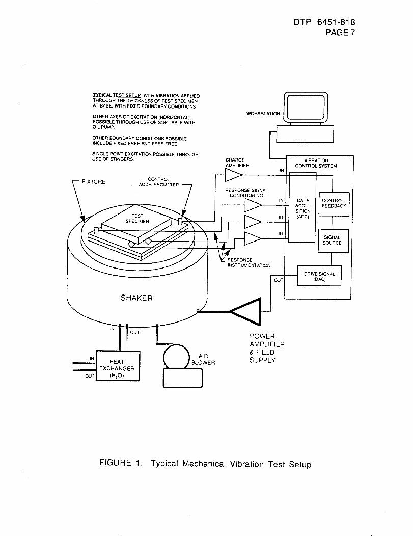
DTP 6451-818
PAGE 7
TYPICAL TEST SETUP. WffH VIBRATION APPLIED
THROUGH.THE-THICKNESS OF TEST SPECIMEN
AT BASE, wri'H FIXED BOUNDARY CONDITIONS
OTHER AXES OF EXCffATION (HORIZONTAL}POSSIBLE THROUGH USE OF SLIP TABLE WITH
OIL PUMP.
OTHER BOUNDARY CONDITIONS POSSIBLE
INCLUDE FIXED-FREE AND FREE-FREE
SINGLE POINT EXCITATION POSSIBLE THROUGHUSE OF STINGERS
CONTROLFIXTURE ACCELEROMETER
TEST
SPECIMEN
SHAKER
WORKSTATION
CHARGE
AMPLIFIER
RESPONSE SIGNAL
CONDITIONING
RESPONSE
INSTRUMENTATION
I
IN
IN
IN
IN
I
IVIBRATION
CONTROL SYSTEM
I
jDATA CONTROL
ACOUI- FEEDBACK
SITION
(ADC) _
SOURCE I
I' IDRI
IN
OUT
INOUT
HEATEXCHANGER
(H20)
AIR
POWER
AMPLIFIER
& FIELD
SUPPLY
FIGURE 1 Typical Mechanical Vibration Test Setup
DTP 6451-818
PAGE 8
WARNING: WHEN WORKING ABOVE OR AROUND THE TEST
SPECIMEN, OR IN AN AREA WHERE OTHER
PERSONNEL MAY BE BELOW, ANY LOOSE
EQUIPMENT THAT MAY BE DROPPED SHALL BE
TETHERED, TO PREVENT DAMAGE TO THE
SPECIMEN OR INJURY.
6.1.1. The vibration test shall be set up and performed according to
standard Rockwell Space Division Vibration Laboratory
practices. Program the vibration control system to performthe following spectra for each axis:
6.1.1.1. X-axis:
20 Hertz to 80 Hertz @ +3 dB/octave,
80 Hertz to 350 Hertz @ 0.067 g2/Hertz,
350 Hertz to 2000 Hertz @ -3 dB/octave;
or TBD.
6.1.1.2: Y-axis:
20 Hertz to 80 Hertz @ +3 dB/octave,
80 Hertz to 350 Hertz @ 0.067 g2/Hertz,
350 Hertz to 2000 Hertz @ -3 dB/octave;
or TBD.
6.1.1.3. Z-axis:
20 Hertz to 80 Hertz @ +3 dB/octave,
80 Hertz to 350 Hertz @ 0.067 g2/Hertz,
350 Hertz to 2000 Hertz @ -3 dB/octave;
or TBD.
6.1.2. Mount response accelerometers on the test specimen, as
requested by the Engineering Test Requester.
6.1.3.
6.1.4.
6.1.5.
DTP 6451-818PAGE 9
Mount the test fixture onto the vibration exciter and installthe control accelerometer on the fixture for the first axisto be tested, per instruction from the Responsible VibrationTest Engineer.
Install the test specimen on the test fixture for vibration inthe first axis to be tested.
Complete instrumentation setup between all transducers andthe data acquisition system. Verify that this setup iscomplete and accurate by performing an end-to-end checkand a calibration recording for all transducer channels. Thecalibration signal shall be recorded on the data acquisitionsystem prior to testing, but not necessarily prior to everytest run if multiple test runs are performed during any oneshift.
6.2. TEST READINESS REVIEW
A Test Readiness Review shall be held between the testrequester and the dynamics test engineer prior to test.
6.3. TEST PROCEDURENOTES
6.3.1. EVENT IDENTIFICATION
The following definitions shall apply:
1. Test- A complete set or subset of vibration test runs on
a specimen.
2. Run- One application of vibration excitation to thespecimen.
6.3.2. TEST PERSONNEL
The minimum test personnel necessary to perform test runs
is one dynamics test engineer, working in coordination with
an engineering test requester. The dynamics test engineermay use a dynamics test technician as an addition or
replacement, when appropriate.
DTP 6451-818PAGE 10
6.3.3. SYSTEM EQUALIZATION/PRELIMINARY TEST RUNS
Preliminary test runs may be necessary to perform systemcheckouts (end-to-end checks), establish test levels, shakerconfigurations, and other parameters, prior to performingactual testing or data runs.
6.3.4. EMERGENCYSHUTDOWNPROCEDURE
An Emergency Shutdown Procedure is in Sub-Appendix A, thelast page of this Mechanical Vibration Detailed TestProcedure.
6.4. TEST RUN PROCEDURES
6.4.1. Verify that all steps in section 6.1 have been completedbefore proceeding.
6.4.2. Verify that the test setup is complete for the first axis to betested and confirm that all test personnel are on line andready to perform their test duties.
6.4.3. Perform vibration for the first axis to be tested. The dataacquisition shall be turned on during vibration equalizationprior to reaching full level, to record all vibration datawhile testing at full level. A minimum of one powerspectral density measurement of the full level controlaccelerometer signal shall be taken.
6.4.4. Mount the test fixture onto the vibration exciter and installthe control accelerometer on the fixture for the second axisto be tested, per instruction from the Responsible VibrationTest Engineer.
6.4.5. Install the test specimen on the test fixture for vibration inthe second axis to be tested.
6.4.6. Complete instrumentation setup between all transducers andthe data acquisition system. Verify that this setup iscomplete and accurate by performing an end-to-end checkand a calibration recording for all transducer channels. The
DTP 6451-818PAGE 11
calibration signal shall be recorded on the data acquisitionsystem prior to testing, but not necessarily prior to everytest run if multiple test runs are performed during any oneshift.
6.4.7.
6.4.8.
6.4.9.
6.4.10.
6.4.11.
Verify that the test setup is complete for the second axis tobe tested and confirm that all test personnel are on line andready to perform their test duties.
Perform vibration for the second axis to be tested. The dataacquisition shall be turned on during vibration equalizationprior to reaching full level, to record all vibration datawhile testing at full level. A minimum of one powerspectral density measurement of the full level controlaccelerometer signal shall be taken.
Mount the test fixture onto the vibration exciter and installthe control accelerometer on the fixture for the third axisto be tested, per instruction from the Responsible VibrationTest Engineer.
Install the test specimen on the test fixture for vibration inthe third axis to be tested.
Complete instrumentation setup between all transducers andthe data acquisition system. Verify that this setup iscomplete and accurate by performing an end-to-end checkand a calibration recording for all transducer channels. Thecalibration signal shall be recorded on the data acquisitionsystem prior to testing, but not necessarily prior to everytest run if multiple test runs are performed during any oneshift.
6.4.12.
6.4.13.
Verify that the test setup is complete for the third axis tobe tested and confirm that all test personnel are on line andready to perform their test duties.
Perform vibration for the third axis to be tested. The dataacquisition shall be turned on during vibration equalizationprior to reaching full level, to record all vibration datawhile testing at full level. A minimum of one powerspectral density measurement of the full level controlaccelerometer signal shall be taken.
DTP 6451-818PAGE 12
6.5. TEST SETUP TEARDOWN
After completion of testing, all instrumentation and othertest equipment shall be removed from the specimen, unlessotherwise agreed to by the engineering test requester andthe test engineer. The test specimen shall be removed fromthe vibration exciter.
6.6. TEST SPECIMEN DISPOSITION
After completion of testing and setup teardown, transferthe test specimen to the test requester or designatedrepresentative for disposition.
7.0. DATA REQUIREMENTS.
7.1. HARD COPIES
Hard copies of data plots, per paragraph 4.2, shall be made
available to the test requester. Sample data sheets are
shown in Figure 2 for accelerometer data and Figure 3 forstrain gauge data.
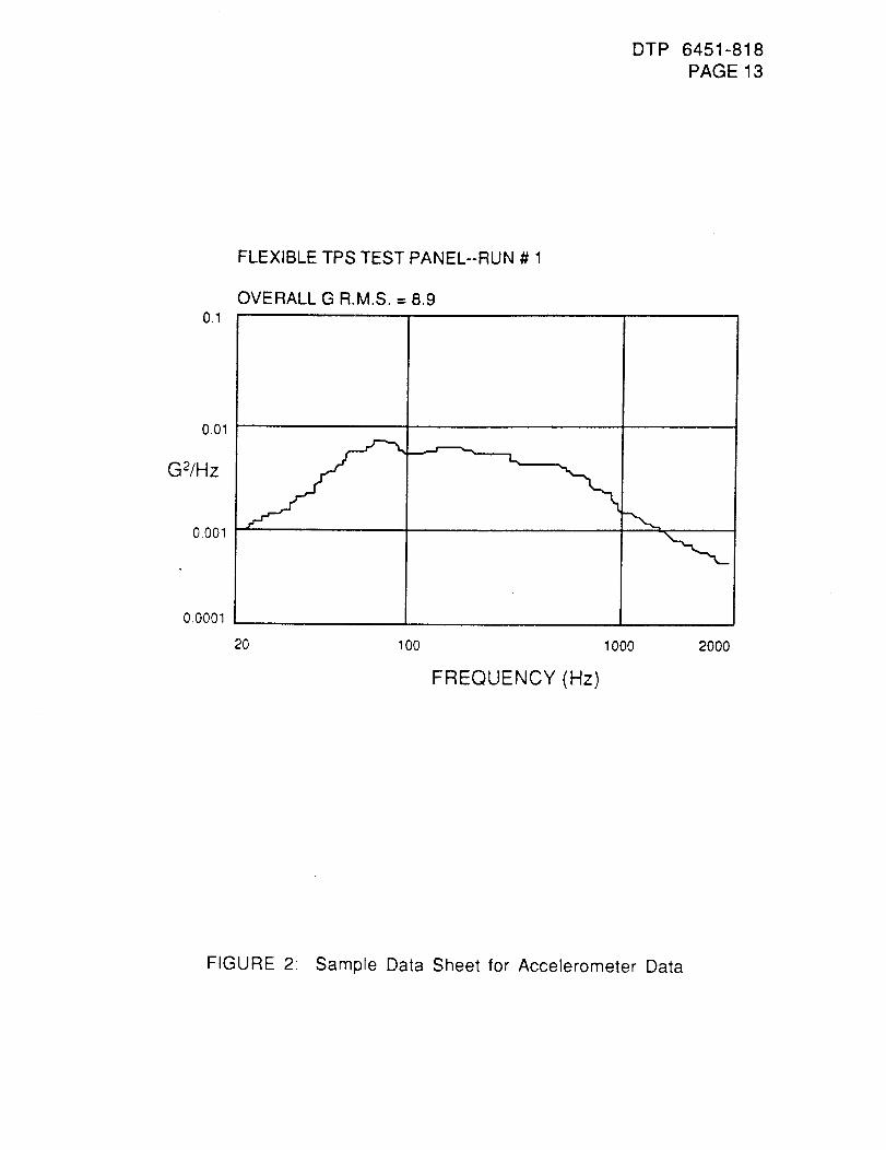
DTP 6451-818PAGE 13
FLEXIBLE TPS TEST PANEL--RUN # 1
OVERALL G R.M.S. = 8.90.1
001
G2/Hz
0.001
O.0001
20 100 1000
FREQUENCY (Hz)
2O00
FIGURE 2: Sample Data Sheet for Accelerometer Data
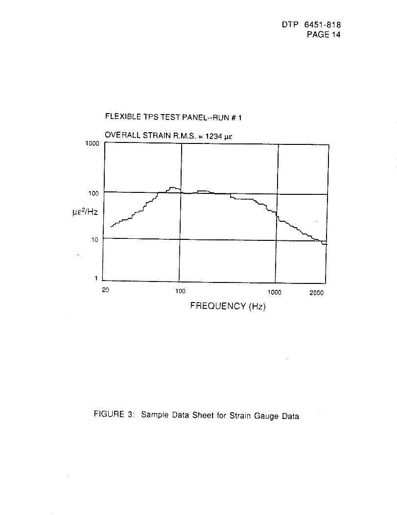
DTP 6451-818
PAGE 14
1000
100
Ij£2/Hz
10
FLEXIBLE TPS TEST PANEL--RUN # 1
OVERALL STRAIN R.M.S. = 1234 pc
, _a-.--.,,m
20 100 1000
FREQUENCY (Hz)
k_
2OOO
FIGURE 3: Sample Data Sheet for Strain Gauge Data
DTP 6451-818
PAGE 15
7.2. DATA FILES
All data for all test runs shall be stored on magnetic media
for the duration of the program, or until the test requester
concurs that the data can be disposed of.
7.3. TEST REPORT
A White Test Report and copies of all Laboratory Notebook
pages shall be prepared and issued to the test requester.
8.0. TEST EQUIPMENT.
The following test equipment will be utilized for the test:
8.1. MECHANICAL SYSTEM.
Vibration test fixture
Shaker (moving element)Reaction mass
Slip table
Oil Pump
Heat exchangerAir blower
8.2. ELECTRICAL EXCITATION SYSTEM
Vibration control system analog to digital converters
Power amplifier and magnetic field power supplyShaker (armature)
8.3. INSTRUMENTATION
Accelerometers
Charge amplifiersTrue R.M.S. voltmeter
Other sensors (optional)
Other signal conditioning (optional)
Vibration control system analog to digital converters
F.M. tape recorder (optional)
Digital data acquisition system (optional)
DTP 6451-818PAGE 16
SUB-APPENDIXA: EMERGENCYPROCEDURES
A.1. EMERGENCYPROCEDURES
• Any member of the test team noting an abnormal
condition shall immediately notify the Dynamics TestEngineer or his designated representative, hereinafterreferred to as the Test Conductor.
2, The Test Conductor has the sole responsibility to orderthe excitation removed during test.
A.2. EMERGENCY SHUTDOWN PROCEDURE
° Upon becoming aware of an abnormal test condition, the
Test Conductor shall immediately make a judgment asto whether the excitation level should be reduced orshut down.
*** NOTE ***
IF THE TEST CONDUCTOR AND THE
ENGINEERING TEST REQUESTER CONCURTHAT THE ABNORMAL TEST CONDITIONS
EXPERIENCED ARE NOT DETRIMENTAL TO
THE TEST SPECIMEN AND THAT DATA
ACQUISITION AT THAT LEVEL OF
EXCITATION WOULD BE ADVANTAGEOUS TO
THE TEST OBJECTIVES, THE ABNORMAL
TEST CONDITIONS MAY BE IGNORED BY THETEST CONDUCTOR AND DATA ACQUISITIONMAY PROCEED.
• At any time an emergency exists that requiresimmediate shutdown, the Test Conductor shall issue
an order for the nearest test personnel to reduce themaster gain.
APPENDIX J
RADIANT EXPOSURE TESTING
DTP 6451 819
PAGE1
THERMAL TEST - RADIANT HEAT TEST PROCEDUREDETAILED TEST PROCEDURE
NRA 8-12, SSTO TA-3
1.0. OBJECTIVE:
The objective of this test is to obtain thermal performance characteristics ofadvanced flexible TPS in a radiant heating environment. The test effort involves
radiant heat testing at surface temperatures up to 2,000OF.
2.0. SCOPE:
This document describes testing defined in Task 1,2, & 3. Changes to this testplan, which are in the scope of the test request, may be made by "redline" changesapproved by the test requester and the responsible test engineer.
3.0. APPLICABLE DOCUMENTS:
4.0. TEST SPE(_IMEN PREPARATION:
Test specimen preparation will be defined in Tasks 1, 2, & 3.
ii:
5.0 TEST SETUP DESCRIPTION:
The test articles will be tested in the Rockwell Environmental Simulation and
Thermal Physics Laboratory radiant heat facility chamber. The effects of insulatingthe back face of the test panel with respect to the back face heating rate and the350F maximum back face temperature are to be established. Insulate the back faceof the test panels
6.0. TEST SPECIMEN INSTRUMENTATION:
Three chrom/alumel, Type k 30 GA thermocouples were woven into the outer fabric
of the blankets to measure surface temperatures during test. Three of the same typeof thermocouples will be symmetrically located and fastened to the back face of each
aluminum sheet. One surface instrumented test specimen shall be available forcontrol purposes.
7.0. GENERAL REQUIREMENTS:
1. When handling of the test specimen or any parts of the test articleassembly, clean cotton gloves or equivalent shall be worn to prevent alkalicontamination. Any physical damage such as accidental surface contamination will
be documented in the laboratory notebook and reported to the engineeringcoordinator.
DTP 6451 819PAGE2
2. The test requester shall be notified in advance of any scheduled test.
3. Color photographs will be taken before and after each run to document thetest article condition.
4. A general visual inspection of the test specimen and fixture shall be madeprior to the start of the test. A complete visual inspection after each sequence will bemade to determine if any damage had occurred.
5. A test report shall be published at the completion of the test program.
8.0. PROCEDURE:
The Rockwell shall provide the facility apparatus, setup, data acquisition, datareduction, and facility detailed test procedure.
Each bonded blanket specimen shall be exposed to static ( constant temperatureand pressure) radiant environments combining surface temperatures of 800,1,100,1,500 and 2,000F with chamber pressures of 0.076 ( or minimum Facilitypressure), 7.6 and 760 TORR. Also, each test specimen shall be exposed to threeradiant mission profiles with maximum surface temperatures of 1,100, 1,500 and2,000 F.
9.0. DATA REQUIREMENTS:
All measurements (including temperature and pressure) are to be continuouslyrecorded during the thermal exposure and for a sufficient length of time following theheating to obtain peak internal temperatures and a cool-down trend. Include aminimum of six test article measurements during a test run.
The test data shall be recorded on magnetic tape and strip charts per facilitycapability. Tabulations and CRT's ( computer plots) will be required.
A copy of the data shall be made available to the test requester and the RTE or theirrepresentative.
10. TEST ARTICLE DISPOSITION:
The test article shall be returned to Rockwell, Laboratories & Test for retention.
11. APPENDIX:
Chamber schematics
Test article/instrumentation drawingTemperature/pressure profile
2
APPENDIX K
VENTING TESTING
DTP 6451-820
PAGE 1
VENTING TESTDETAILED TEST PROCEDURE
NRA 8-12, SSTO TA-3
INTRODUCTION
This Detailed Test Procedure (DTP) defines the venting test for the TPS materialdeveloped in the different tasks of TA-3. The specimen material, configurationand in venting tube instrumentation will be specified by each task.
OBJECTIVE
The objectives of this test are to determine the differential pressure between
ambient and the interior of the test article, the pressure gradient across theinterior of the specimen at various depths, and if the material can withstand thedifferential pressure.
SCOPE
This document contains the test requirement and the detailed test proceduresrequired to conduct the venting test. This test will be conducted at the Rockwell
test facility. Changes to this plan which are in the scope of the test request maybe made by "Redline" changes approved by the Responsible Test Engineer(RTE)
APPLICABLE DOCUMENTS
• Rockwell Laboratory notebook for recording observations during testing.
• Disposition Record From for recording test deviations and anomalies duringtesting.
GENERAL REQUIREMENTSDocumentation
Detailed Test Procedure (DTP)
The test will be conducted in accordance with this procedure.
Laboratory Notebook
A Laboratory Notebook will be maintained by the L&T RTE depicting a completetest history. Test article configuration, instrumentation, test anomalies andmalfunctions and all other pertinent data and information will be recorded.
Test Report
The test agency will issue a Laboratory Test Report (LTR). The test report willdepict the complete test program, instrumentation, brief test procedures andresults, test setup including photographs, test data and other pertinentinformation.
Notification
The RTE shall be notified in advance of any scheduled test.Test Facifity
The test will be conducted in Bldg. 299, Environmental Systems Laboratory.
DTP 6451-820PAGE 2
Instrumentation
All measurement instrumentation will be calibrated and have a decal showing avalid calibration due date. A list of test instrumentation will be maintained in a
Laboratory Notebook showing name/description, metrology number andcalibration due date.
Test Conduct
The test program will be conducted under the direction of a test conductor who
will be the L&T RTE or his designated representative.
TEST SPECIMEN
Specimen number and material will be defined by each task. the specimensshall be identified and instrumented with pressure tubes. The number ofpressure tubes and depths of tubes to be instrumented in the specimen will bedefined.
TEST SETUP
See Fig. 1 for instrumentation of pressure tube in the test specimen and Fig. 2for test system schematic.
Pretest Verification
- Verify that all instrumentation and calibrated equipment are recorded in theLaboratory Notebook.
• Verify that all pressure tubes are properly connected to pressure transducersand the tube is clear and unbent, and reaches the required depth of thespecimen.
• Verify that all 13 pressure transducers channels indicate ambient pressureon LDS.
Photograph test specimens and the test setup.Start the diffusion pump per next paragraph.O.K. to close the vacuum chamber.
Diffusion
• VerifyPump Startupthat the pump cooling water is on.
Start the foreline pump (FP-1 to the "ON" position).
Verify that light FP-1 on the system schematic panel is running.Open the foreline valve (FV-1 to the "ON" position).Verify that light FV-1 on the system schematic panel is illuminated.Verify that the foreline pressure decreased to less than 50 microns.
Turn on the diffusion pump heater (DTP-1 to the "ON" position).Verify that light DP-1 on the system schematic panel is illuminated.
TEST PROCEDURES
The ascent and reentry pressure profiles will be defined.examples of Orbiter profiles.
See Fig. 3 and 4 for
Ascent Profile
DTP 6451-820
PAGE 3
Verify that the chamber door is closed.Verify that the chamber isolation valve is in the "CLOSED" position.Verify that the pump position switch is in the "OFF" position.Activate the MICON Valve Controller and 28 VDC Power Supply.At MICON Valve Controller:
Set Computer/Auto/Manual mode select switch to "MANUAL".Set Process Feedback/Error/Valve Command switch to "ValveCommand".
Verify that lower LED display indicates 00.0% (fully closed position).(Note: If the display shows other than zero, press Increment/Decrementswitch down until the display shows zero.)Set Process Feedback/Error/Valve Command switch to "ValveCommand".
Verify that lower LED display indicates around 95% (ambient).• Verify that Data Trak curve following probe is in the ascent profile program
starting point.• Verify/position Data Trak mode select switch to "REMOTE".
• Start the 300 CFM roughing pump.• Open the chamber isolation valve.• Set the pump position switch to "PUMP VALVE OPEN".• Set LDS System at one second sample rate.• Set Data Trak mode select switch to "RUN".• Set Computer/Auto/Manual switch to auto at MICON valve controller.
• Verify the proper DATA TRAK operation (Monitor the curve following probeposition vs. set point).
• At the completion of the ramp:Set DATA TRAK mode select switch to "RUN"
Change LDS sampling rate to 20 second interval.• Continue to pump down the chamber until the chamber pressure reduces
below 50 microns.
• Set Computer/Auto/Manual switch to auto to "MANUAL".• Set Process Feedback/Error/Valve Command Switch to Valve Command.
• Press Increment/Decrement switch down until lower LED display indicates0.00%.
• Verify that the diffusion pump is ready for pumping.• Open the high vacuum valve.• Reduce the chamber pressure to 10 (-3) torr or lower. Hold for 15 minutes
minimum.
• Close the high vacuum valve.
• Proceed to next paragraph to simulate entry pressure profile.
Entry Profile
• Verify that DATA TRAK curve following probe is in the entry profile programstarting point.
• Verify/Set Computer/Auto/Manual selector to "MANUAL".• Verify/Set Process Feedback/Error/Valve Command selector to "Valve
Command"
• Verify that lower LED display indicates zero (0.00%)
DTP 6451-820PAGE 4
Set Process Feedback/Error/Valve Command selector to "ProcessFeedback".Activate LDS at one second sample rate.Position Data Trak mode selector to "RUN".Set Computer/Auto/Manual selector to "AUTO".At the completion of the ramp, secure the system as follows:Set Data Trak mode select switch to "HOLD".Set Computer/Auto/Manual switch to "MANUAL".Set Process Feedback/Error/Valve Command switch to "VALVECOMMAND".Verify that lower LED display indicates zero.Verify that the pump position switch to "PUMP VALVE CLOSE". (ambient)Turn off the 300 CFM roughing pump.
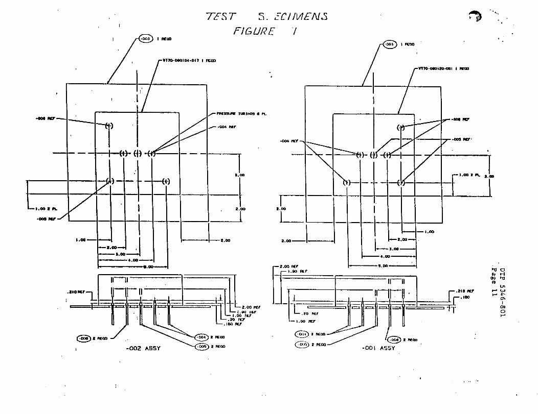
-004 Iqar .---.
--,-IoO0 • Ft.
-OCm II/' -/
t
¥1rm-ogQID4-OIT I IrTT.QO
d
--_ . _-_- ....
- !
/
2,00
L , I | t
i----Io 10_
o
_ |.00-.._..,
4. O0 ,-,_-._
I1.00-------.
•"°---L I II--Lr-"__.
I -002 A55Y _ z _o
TES T S. ZC //V/EA/.I
�:-/&LIME i
_l'T'lgs_LqE lrtBl_Q_ •
_-.-IX)4 F_T
m m
1Z.CO
1
3.00
L
i
/
)--/
i !
_,.- | 0Q_
_.1.OO _
4.00
-001ASS¥
i,,,n°
r-z._ ,_r , OOll__lI •"t_[ I._) R[T
• 2771' -fL .
IPt_O
/ -002 117'.
[
o
I1.00 I1_. .I.00
19LJ1
I--' _J
I
O0
0
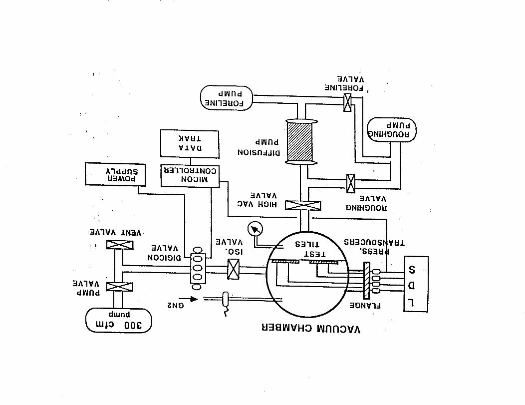
din fld
NI'I3EIO:I
i
U3MOd
I,
3AqVA
"OSI
3A3VAOVA HDIH
dlNF
EI381NVHO INNI'iOVA
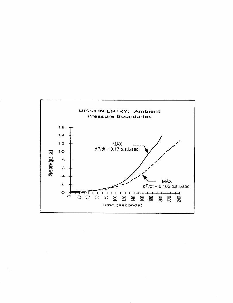
MISSION ENTRY: Ambient
Pressure Boundaries
16
14
12
_- 10
_- 8
2
0
MAX -'---x / z /
_ dP/dt = 0.17 p.s.i._,/,/'/
_ dP/dt = 0.105 p.s.i./sec.! : : | " ; ; " " | I I ," " " ; ,' " " " ; ," " I
O O O O O O O O O O O O O
Time (seconds)
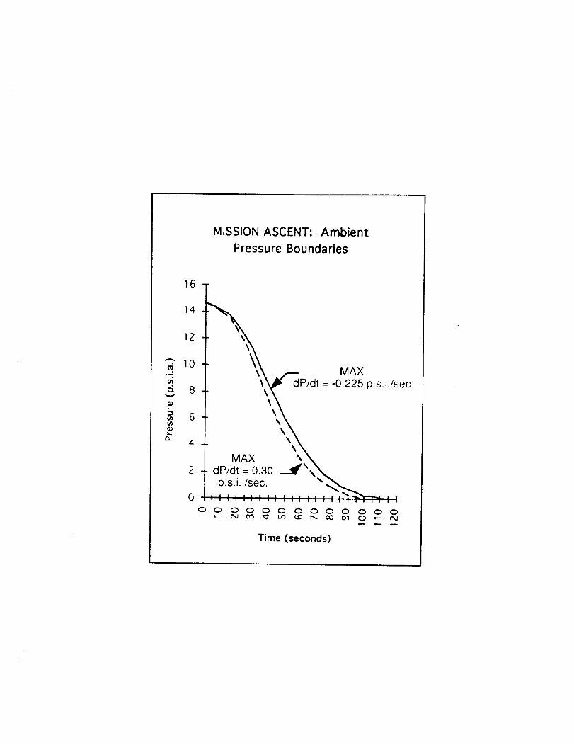
MISSION ASCENT: Ambient
Pressure Boundaries
16
14
12
_" 10
6. 8
6
=- 4
2
0
\
MAX
'__P/dt = -0.225 p.s.i./sec
MAX \ \
= 0.30 ----._._"\___dP/dt
O C) O O O O O O O O O O O
Time (seconds)
APPENDIX L
AIR IMPINGEMENT TESTING
AIR IMPINGEMENT TEST
DETAIL TEST PROCEDURE
NRA 8-12, SSTO TA-3
DTP 6451 - 822
PAGE 1
OPERATING PROCEDURE FOR AIR IMPINGEMENT TEST APPARATUS
The following procedure stipulates guidelines for the system operation and
performance of the air impingement test apparatus.
I. Test Parameters: The following test parameters are in general used forestablishing test conditions of the upstream jet stream and its relative
direction prior to impact at the surface of the test coupons.
1.1 Scenario one - Continuous jet stream impingement.
This scenario simulates a continuous bombardment of air jet stream on the
surface of the test coupon under the following conditions:
Test variable parameters:
1. Angle of impingement ( ) relative angle of impingement between the
upstream jet direction with respect to the orientation of the planarsurface of the test coupon.
Note: The upstream jet is defined as the jet stream prior to impact.
2. The exit velocity of the jet stream (V) the velocity of the jet streamas it exits the nozzle. Since it is difficult to directly measure this
parameter, it is usually calculated based on the following measurablequantities:
• Exit pressure
• Supply pressure• Volumetric flow rate
• Cross-sectional area at the exit of the nozzle
• Cross-sectional area at the supply line
1.2 Scenario two Intermittent air stream impingement
This scenario simulates a pulsing effect of air jet impingement on the
surface of the test coupons which exerts a stronger aerodynamicloading on the surface of the test coupons than that of scenario one.
DTP 6451 822PAGE 2
All the required parameters are the same as before with one additionalparameter (the speed of the chopper) which is usually expressed interms of frequency, Hz. The chopper is positioned between the upstreamjet stream and the test coupon.
I1. Procedure
•
.
Select the specific gas as a working fluid. The most commonly used gasis air. For short duration (less than 30 minutes), plant air can be used.
For long duration (greater than 30 minutes), it is recommended that dryair or gaseous nitrogen be used. Plant air is always contaminated with
oil, and as a result the oil particles will be deposited onto the surface
of the test coupons upon impact. Using gaseous nitrogen or dry air willeliminate the oil contamination.
Determine the angle of impingement• This angle is obtained from theactual situation.
3. Determine the configuration of the nozzle to be used.
.
,
,
°
The configuration of the nozzle depends upon the size of test coupon,
the required test conditions, etc. However, it is limited by theadaptability to the existing test apparatus. The range of nozzle size isfrom 1/4 -inch to 1-inch diameter tube.
Evaluate the required differential pressure between the supply line andthe nozzle exit from the given exit stream conditions, nozzle
configuration, supply line size and pressure, and appropriate flow range.
From the known supply pressure, obtain the appropriate pressure rangefor the exit analog pressure gage.
Note: For safety purpose, it is required that the desired range for theanalog pressure gage should be twice the maximum measuredpressure.
Similarly, select the appropriate pressure range for the supply pressuregage based on the known supply pressure.
Install a relief valve downstream of the supply pressure gage to protectthe hardware from exploding in case of an accidental overpressurization.
DTP 6451 - 822PAGE 3
8. Mount the nozzle to the exit of the test apparatus.
9. Install test coupon to an adjustable test platform which is equippedwith three-dimensional adjustments.
10 Rigidly secure the test coupons to the platform.
11.Select two rectangular bar strips whose thickness is approximately1/4 inch.
12.Insert two rectangular bar along the length of the test coupon with aspacing approximately the length of the nozzle.
13.Overlay an 1/8 inch Plexiglas over the bar strips and securely clampthe entire assembly to the platform.
Note: The complete assembly will have a rectangular channel runlongitudinally along the test coupon. This channel provides aguide for the flow of jet stream after impingement.
14. Position the nozzle to align with the channel (step 12) on the testcoupon.
15. Adjust the direction of the platform with respect to the nozzleorientation to meet the required angle of impingement.
16. Adjust the lateral direction to make sure it is horizontal..
17. Set the chopper frequency:
• There is no direct indication of the frequency (speed) of the chopperduring operation. However, an indirect way of setting the frequency isusing stroboscope.
Scribe a radial line on the back face of the chopper.
Loosen the thumb nut which secures the shaft to the motor.
Convert the required frequency from Hertz into RPM which is the unitregistered on the dial of the stroboscope.
Set the required RPM on the dial.
DTP 6451 - 822PAGE 4
Position the stroboscope with the flashed light point toward the scribedmark on the chopper surface.
• Turn the power on to the chopper.
• Adjust the thumb nut and locate the scribed mark on the chopper.
• The chopper frequency will be achieved when the scribed mark remainsstationary with respect to you.
• Secure the thumb nut to lock in the desired setting for the chopper.
• Remove the stroboscope.
• Leave the chopper rotating
18. Since the test coupon will be exposed to the desired conditioninstantaneously, it is recommended that a shield is placed in front ofthe exit jet stream to deflect the jet stream away from impacting thetest coupon.
19. With the shield in the way, gradually regulate the supply air to producethe required exit test condition.
20. Verify that the required test conditions from the instrumentationoutputs.
21. Remove the shield when the test conditions were achieved andsimultaneously start the timer.
22. Allow the air to flow for a predetermined test duration or until failurewhichever is required.