technology for radioactively contaminated wastewater...
TRANSCRIPT
Technology for radioactively contaminated wastewaterfrom the nuclear power plants
processing.
Danube WATER Project, MIS ETC 166
Technology for radioactively contaminated wastewater from the nuclearpower plants processing.Data for reporting: 01.07.2015
PROJECT MANAGER Dr. Mary-Jeanne ADLER
PROJECT RESPONSIBIL PP6Dr. eng.Aurelia PISCUREANU
PROJECT RESPONSIBIL PP7Dr. Arsene Carmen
PROJECT RESPONSIBIL PP8Prof.Dr.eng. Dima RomulusDr.eng. Dinculescu DanielDumitru
PROJECT RESPONSIBIL PP13Assoc. prof. Dimitar TONEV
EXPERTS CONTRIBUTING PP6 – ICECHIM
EXPERTS CONTRIBUTING PP7-RATEN-ICN
Aurelia PISCUREANUDana VARASTEANUIrina CHICANMircea RUSEGeorgeta NEGRAUMariana MATEESCUCarmen ANDREIASNicolae TIGANILA
Arsene CarmenDulama MirelaDeneanu NicoletaDianu MagdalenaOlteanu MirelaBujoreanu DănuţBujoreanu LilianaIchim CameliaBadea SilviuPătrulescu PetreIvan ConstanţaIoniţă AureliaBobaru Constantin
EXPERTS CONTRIBUTING PP8-UPB
EXPERTS CONTRIBUTING PP13-INRNE
Cârlanaru VasilePopescu Felicia
Dinculescu Daniel DumitruGijiu Cristiana LuminitaMares Alina Monica
Prof. Kiril Asenov KREZHOVAssoc. prof.Tsvetana PetrovaNONOVAAssoc. prof. Anna AndreevaDAMIANOVAAssoc. prof. Hristo NedialkovPROTOHRISTOV
Liuben Todorov DOBREVAssoc. prof. Lachezar StoyanovGEORGIEVPetko Borislavov KRASTEVTsvetana JordanovaSIMEONOVAZahari Rangelov ZAHARIEVSevka Velcheva IVANOVANeli Nikolaeva ZAHARIEVAElena Georgieva GELEVAAlexandar Dechkov MLADENOVBozhidar Slavchev SLAVCHEVEvgeni Petrov POPOV
National Research & DevelopmentInstitute for Chemistry & Petrochemistry– ICECHIM, Bucharest RO– PP6
Authonomus Company of Technologiesfor Nuclear Energy – Institute forNuclear Research, Piteşti RO – PP7
University POLITEHNICA of BucharestRO – PP8
The Institute for Nuclear Research andNuclear Energy, Sofia BG – PP 13
“Danube WATER Integrated Management”
Technology for radioactively contaminated wastewater from thenuclear power plants processing
Leader of working group for Activity 12: National Research & Development Institutefor Chemistry & Petrochemistry – ICECHIM – PP6
Legal representative: Project Coordinator: PhD Sanda VELEA PhD Aurelia PISCUREANU
a
CONTENT
1. INTRODUCTION…………………………………………………………………….. ……...11.1 The purpose and importance of work performed ………………...............................……....11.2 Legal basis ……………………………………………………………………...……. …........31.3 The phases of research performed ……………………………………………..…... …........42. PERFORMED WORKS AND THEIR RESULTS…………………………….…… .….......52.1 Laboratory works.……………………………………………………………….…... ..……..5
2.1.1 The laboratory works performed at ICECHIM, in non-radioactive simulatedsystem……………………………………………………………..………..…….……….. …........5
2.1.2. The laboratory works performed at ICN Pitesti, with radioactive waste waterstype CANDU .……………..……………………………………………………….……... …........9
2.1.3. The laboratory works performed at IRNE Sofia, with radioactive wastewatertype Kozloduy technology …….………………………………………………….….…… …......12
2.1.4. Modeling of laboratory procedure …...…………………………………………...…......292.2 Pilot scale testing of the decontamination process of radioactive wastewater fromCernavoda NPP ………………………………………………………………………...….…......33
2.2.1. Ion exchange resins used within experiments …………………………………...…......332.2.2. Aqueous radioactive waste processed………………………………..…..……... …......332.2.3. Methods and apparatus ………………………………………...…………….…. …......332.2.4. Test description …………………………………………………………….….... …......342.2.5. Experimental results……………………………………………………….…… …......36
3. TECHNOLOGY FOR TREATMENT OF AQUEOUS RADIOACTIVE WASTEFROM CERNAVODA NPP……………………………………………….……………. ……..383.1 Flow chart of technology for treatment of liquid radioactive waste fromCernavoda NPP………………………………………………………………………….. …......383.2 Pilot installation design…………………………………………………………….... …......423.3 Operation procedure……………………………………………………………….... …......46
3.3.1 Preparing ion exchange resins for utilization…………………………………... …......463.3.2 Preparing pilot- installation for operation………………………………………. …......463.3.3 Loading the columns with ion exchange resins………………………………………......463.3.4 Settleable solids separation and organic phase separation......................................…......473.3.5 Aqueous radioactive waste clean-up......................................................................... ….....473.3.6 Effluent storage and discharge……………………………………………………..…......483.3.7 Discharging spent ion exchange media…………………………………………. …......48
3.4 Processing parameters for treatment by ion exchange of aqueous radioactivewaste from Cernavoda NPP…………………………………………………………….. …......48
3.4.1 Chemical and radiochemical characteristics of aqueous radioactive waste……....…......493.4.2 Selected ion exchange resins – characteristics………………………………….. …......503.4.3 Establishing parameters which control the ion exchange resins performances….…......503.4.4 Influent flow rate and flow velocity through ion exchange resin bed………….. …......51

b
4. RECOMMENDATIONS ON THE TYPE, DIMENSIONING OF SPECIFICEQUIPMENT AND CONSTRUCTION MATERIALS................................................. ….....525. RECOMMENDATIONS ICN ON THE WORK SAFETY MEASURES……….... …......646. RECOMMENDATIONS ON THE WORK SAFETY MEASURES AT INRNE… .........667. SUMMARY OF THE RESULTS AND CONCLUSIONS……………….................... ……..697.1 Technology efficiency……………………………………………………………...…... .........697.2 Cost consideration…………………………………………………………………....... .….....71REFERENCES……………………………………………………………………..…....... ...…...73
1
1. INTRODUCTION
1.1 The purpose and importance of work performed.
In Romania is in force the Order no. 156/2005 of CNCAN President for approval of regulation on
the classification of radioactive waste [1].
According to this regulation, radwaste is placed in following categories: excluded radioactive waste
(EW), transitional radioactive waste (TW), very low level radioactive waste (VLLW), low and interim
level short lived radioactive waste (LILW-SL), low and interim level long lived radioactive waste (LILW-
LL) and high level radioactive waste (HLW), based on the requirements for assuring the isolation from
biosphere during the radioactive waste disposal.
Our activity refers to low level waste, which contains radioactive and non-radioactive components
that may affect humans and the environment. Therefore the management of such wastes should take into
account both radioactive and non-radioactive components and their associated hazards.
Waste characterization is necessary to ensure the selection and application of appropriate treatment
and conditioning options to satisfy requirements for waste storage and final disposal to protect human
health and the environment.
In defining the required treatment for stabilization of each waste stream, it is necessary to identify
the radioactive and non-radioactive hazardous constituents. For both the radionuclides and the chemically
toxic contaminants, it is important to know their chemical forms and concentrations. It is also important
to have an understanding of their expected behavior in treatment processes, their toxicity, and the
potential release rates of the components from the final waste form.
Treatment of liquid radioactive waste involves the application of several steps such as filtration,
precipitation, sorption, ion exchange, evaporation, membrane separation to meet the requirements both
for the release of decontaminated effluents into the environment and the conditioning of waste
concentrates for disposal [2]
At Cernavoda NPP [3] radioactive wastes waters level 1 – from the laundry, underground drainage
pits of the spent fuel bay, the underground drainage pits of shower rooms, laboratories, floor drainage,
with radioactivity ranging between 3.7x10² Bq/l and 3.7x10⁻¹ Bq/l and level 2 from the heavy water
upgrading system, the equipment decontamination system, rubber objects laundry with radioactivity
ranging between 3.7x10⁴ Bq/l and 3.7x10 Bq/l.. Level 3 are higher radioactive wastes – resulting from the
reactor drainage systems, spent fuel storage bays, spent resin storage vaults, whose radioactivity ranging
between 3.7x10⁶ Bq/l and 3.7x10⁴ Bq/l

2
The liquid wastes are collected in five epoxy concrete vaults (50 m3) located in the S/B basement.
Two of the vaults are used for the collection of the level 2 and 3 radioactive wastes; the other 3 vaults are
aimed to collect the level 1 low radioactive waste.
The capacity of each vault (50 m3) represents about the double capacity of the daily average
quantity of radioactive liquid wastes produced by the plant so that the system can accommodate possible
emergencies or abnormal situations of the plant operation.
Normally, the liquid waste radioactivity is sufficiently low so that the discharge may be allowed
without any previous decontamination. For special cases in which such decontamination is mandatory, an
ion-exchange filter, a feed pump and the necessary auxiliary equipment is provided.
The radioactivity of the discharged wastes is continuously measured by Liquid Effluent Monitor
which, when the limit value of 5x10³ Bq/l is reached automatically closes the discharge pipe line circuit
and the water is to be directed back into the vault for analysis and decontamination.
Kozloduy NPP [4] have WWER–440 and WWER-1000 reactor units. These were constructed
using a “double-unit” concept — two reactors, one common auxiliary building. The following storage
facilities were foreseen:
·8300 m3 for evaporator concentrates
·2300 m3 for spent resins
·4500 m3for LILW dry solid waste.
Danube river, using its water for plant cooling needs as well as a recipient for liquid releases.
National environmental limits significantly restrict release of boron containing compounds.
The possible solutions for reduction of waste are:
·boric acid recovery system for primary circuit water (primary coolant) for WWER-1000 reactor
units
·evaporator- distillate can be re-used as make-up water.
· partly replaced of insulating wool by reusable material.
· improved maintenance of pump seals and drain valves to avoid leaks.
The technology for conditioning of both solid and liquid waste is based on cementation method,
using steel-concrete container as a package.
The technology for liquid waste conditioning includes following processes:
· Transportation of liquid waste from the storage tanks in the nuclear unit’s auxiliary
· buildings to the liquid waste processing facility
· Concentration of the liquid liquid waste (if necessary) through evaporation,
· Cementation and filling the mixture in a package (steel-concrete container).
3
An additional system for decontamination of metal liquid wastes was placed in the facility’s
building.
References indicate that the ion exchange resin is used in the water purification system both in
nuclear research and power reactors. Combined with active carbon, the resin removes the dissolved
elements from water when the nuclear reactor is operating. After its consumption, it becomes a special
type of radioactive waste. The usual treatment of this type of waste is the immobilization with Portland
cement, which is simple and low cost. However, its low capacity of immobilization and the increase
volume of waste have been the challenges.
For the conditioning of ion-exchangers generated from operation of Cernavoda NPP Unit 1
techniques of direct immobilization in cement, bitumen and organic polymers have been experimented
within ICN Pitesti. The selected process for conditioning of spent resins is their bituminization. In view of
final disposal, the container that includes the waste bitumen block is cemented and confined in another
with a larger capacity [5].
According to those above presented, we focused in this project on developing an efficient
technology, based on ion exchange resin (nuclear use type), for decontamination of radwaste waters
resulting from Cernavoda.and Kozloduy NPP.
1.2. Legal basis
The works for elaboration technology for decontamination of aqueous radioactive waste from
Cernavoda and Kozloduy NPP were objective of the 12th activity “Elaboration of a new technology for
wastewater processing and conditioning the organic liquid wastes radioactively contaminated from
nuclear power plants” within cross-border Romania Bulgaria MIS-ETC WATER 161 project – Danube
water integrated management.
Partners who have implemented this activity were:
· National Research and Development Institute for Chemistry and Petrochemistry- ICECHIM
Bucharest Romania – partner 6 in the project;
· Institute for Nuclear Research (under Regia Autonoma Tehnologii pentru Energie Nucleara-
RATEN)Mioveni, Romania- partner 7 in the project;
· University POLITEHNICA of Bucharest, Romania- partner 8 in the project;
· Institute for Nuclear Research and Nuclear Energy-IRNE, Sofia Bulgaria, partner 13 in the
project.
4
1.3. The phases of research performed
Development of the technology for radwaste waters decontamination was conducted in two phases,
in the project called subactivities:
· 12.1- Elaboration of a new technology for processing the waste waters from the nuclear plants
Cernavoda and Kozloduy. The results were presented in Technical report No.1- December 2013.
· 12.3Testing the technology for processing the waste waters from the nuclear plants Cernavoda and
Kozloduy final document may 2015.
5
2. PERFORMED WORKS AND THEIR RESULTS
2.1. Laboratory works
The goal of activity 12.1, carried on by ICECHIM specialists together with those of Romanian
partners organizations in the project –RATEN-ICN, UPB and Bulgarian partner –PP13-INRNE is to
elaborate the technology for decontamination of radioactive waste waters, with low radioactivity, from
Cernavodă and Kozloduy NPP.
The experimental works carried by Romanian partners had the goal to study the removal of
radionuclides (Co, Cs, Ag,) and some surfactants (linear alkyl benzene sulfonic acid sodium salt –
LABSNa) from aqueous radioactive waste by applying the ion exchange resins- column technique. The
LABSNa anionic surfactant was selected in the experiments because it’s the main component of cleaning
products and in this case, the radioactive waste waters might contain such contaminated ions after the
equipments from the nuclear plants are washed.
Since the decontaminated solution contains a mixture of anionic surfactant (LABSNa) and cations,
both anionic and cationic resins are required for decontamination.
The experiments were performed first in a simulated non-radioactive mono-component or bi-
component system (LABSNa and/or a cation), and then are checked in radioactive multi-component
system.
Bulgarian partner-PP13 has conducted laboratory experimental works for removal radionuclides Sr,
Fe, Ni and Pu from simulated secondary waste from the decontamination processes, applied at Kozloduy.
2.1.1. The laboratory works performed at ICECHIM, in non-radioactive simulated system
The experimental works carried out in simulated non-radioactive mono-component or bi-component
systems have used solutions which contain cations: cobalt and/or sodium, and anions: chlorine and/or
LABS-.
Experiments in simulated non radioactive system were conducted in an installation consisting of:
· glass column containing ion exchange resin with inner diameter of 1.8 cm and height of 20 cm.
Height of the ion exchange resin was varied between 4.5 and 10 cm, and the flow passage of the solution
through the ion exchange resin was varied between 0.83 cm3/min (50 cm3/h) and 6.67 cm3/min (400
cm3/h);
· dropping funnel with a volume of 500 mL, for transfer the solution (simulated) containing cobalt
ions and/or LABSNa into the glass column;
· collection vessel for effluent [6].
In the experiments were tested the following ion exchange resins from Purolite Comp:
6
NRW 160- Cationic exchange resin for nuclear use: Ionic form: H+; Strong acid cation; Total
capacity 2.1 eq/L; Moisture retention: 43-48 %. Application: Polishing steam generator blow down and
layering on polishing mixed beds. Primary purification cation beds for delithiation and outage clean
up.Selective for137Cs.
NRW 1600- Cationic exchange resin for nuclear use: Ionic form : H+ Strong acid cation; Total
capacity 2.1 eq/L; Moisture retention: 43-48 %; Mean diameter: 570 ± 50 μm; Application: Cation resin
vessels or layering for added cation capacity.
NRW 5050 Anionic exchange resin for nuclear use: Ionic form: OH- Macroporous Strong Base
Anion; Total capacity 0.9 eq/L; Moisture retention: 53-58 %; Application: Porous structure designed to
give greater resistance to surface fouling in a wide range of nuclear applications.
NRW 3550 Mixed bed products for nuclear use: Ionic form H+/ OH-; Cation capacity: 2.1 eq/L;
Anion capacity: 0.9 eq/L; Equivalent ratio: 1:1 Macroporous/Macroporous; Application: primary
polishing and cleanup systems, steam generator blow down demineralization for high organics water and
boron removal.
Selection of the optimal type of resin was performed by evaluating the following parameters:
·breaking point (selection criteria–highest value) and
·saturation point (selection criteria – the largest volume of waste).
Analytical methods in simulated systems
Determination of Anionic Surfactants (LABSNa) through two-phase titration
The analytical method is based on titration of anionic surfactant with a cationic surfactant (Hyamine
1622 –Benzethonium chloride) in the presence of an indicator which consists of a mixture of cationic dye
(Dimidium bromide) and an anionic dye (Disulphine Blue). Titration takes place in two phases, the
aqueous phase and chloroform phase, at the end point the organic phase turning from pink to blue-gray.
Content of LABSNa [mg/L] = V x f x d x 348 x 0.004
Where: V is the volume of 0.004 M Hyamine solution used at titration; f is the correction index for
0.004 M Hyamine solution; d is the dilution ratio; 348 is molecular weigh of LABSNa.
Determination of cobalt content
The method is based on Co complexation with ethylenediaminetetraacetic acid disodium salt
(dihydrate) in the presence of murexid as indicator.
Content of Co2+ [mg/L] = 5893.0´´´ dfV , where:
V is the volume of 0.01 M of Complexon III used for titration; f is the correction index for solution
0.01 M of Complexon III; d is the dilution ratio; 0.5893 the amount of Co2+ corresponding to 1 mL of
0.01 M of Complexon III.
7
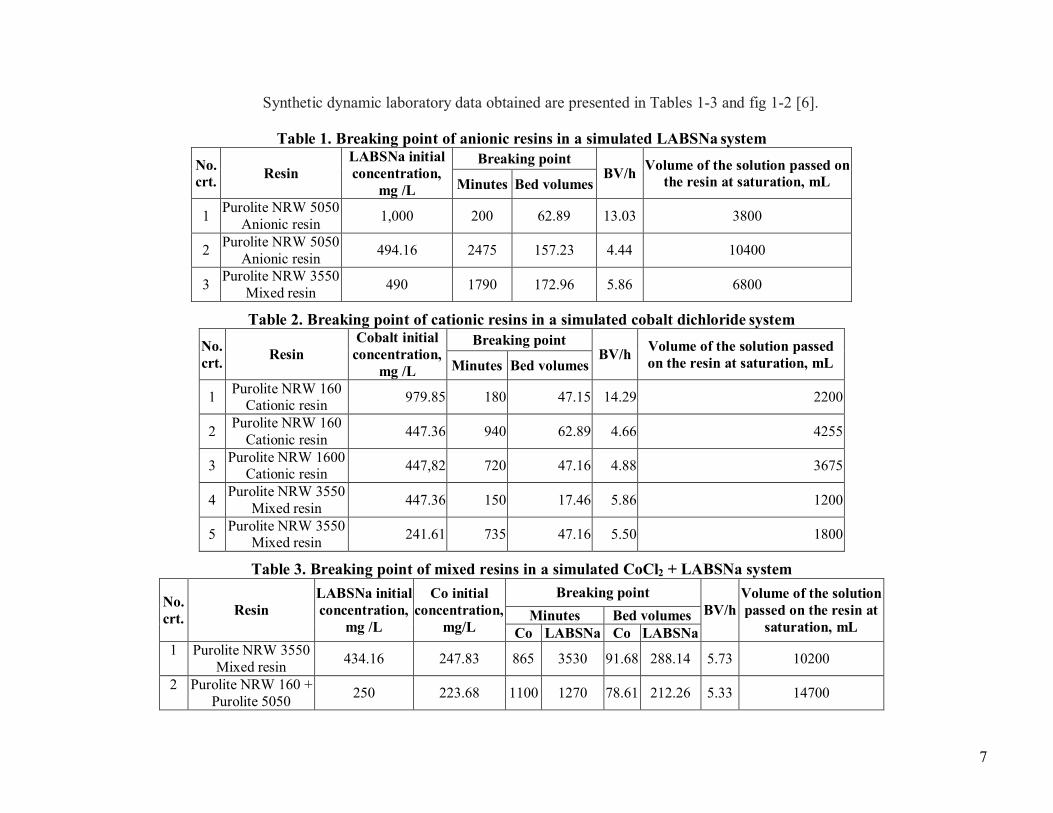
Synthetic dynamic laboratory data obtained are presented in Tables 1-3 and fig 1-2 [6].
Table 1. Breaking point of anionic resins in a simulated LABSNa systemNo.crt. Resin
LABSNa initialconcentration,
mg /L
Breaking pointBV/h Volume of the solution passed on
the resin at saturation, mLMinutes Bed volumes
1 Purolite NRW 5050Anionic resin 1,000 200 62.89 13.03 3800
2 Purolite NRW 5050Anionic resin 494.16 2475 157.23 4.44 10400
3 Purolite NRW 3550Mixed resin 490 1790 172.96 5.86 6800
Table 2. Breaking point of cationic resins in a simulated cobalt dichloride systemNo.crt. Resin
Cobalt initialconcentration,
mg /L
Breaking pointBV/h Volume of the solution passed
on the resin at saturation, mLMinutes Bed volumes
1 Purolite NRW 160Cationic resin 979.85 180 47.15 14.29 2200
2 Purolite NRW 160Cationic resin 447.36 940 62.89 4.66 4255
3 Purolite NRW 1600Cationic resin 447,82 720 47.16 4.88 3675
4 Purolite NRW 3550Mixed resin 447.36 150 17.46 5.86 1200
5 Purolite NRW 3550Mixed resin 241.61 735 47.16 5.50 1800
Table 3. Breaking point of mixed resins in a simulated CoCl2 + LABSNa system
No.crt. Resin
LABSNa initialconcentration,
mg /L
Co initialconcentration,
mg/L
Breaking pointBV/h
Volume of the solutionpassed on the resin at
saturation, mLMinutes Bed volumes
Co LABSNa Co LABSNa1 Purolite NRW 3550
Mixed resin 434.16 247.83 865 3530 91.68 288.14 5.73 10200
2 Purolite NRW 160 +Purolite 5050 250 223.68 1100 1270 78.61 212.26 5.33 14700
8
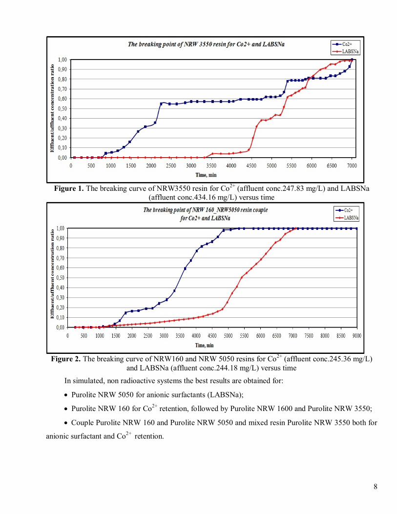
Figure 1. The breaking curve of NRW3550 resin for Co2+ (affluent conc.247.83 mg/L) and LABSNa(affluent conc.434.16 mg/L) versus time
Figure 2. The breaking curve of NRW160 and NRW 5050 resins for Co2+ (affluent conc.245.36 mg/L)and LABSNa (affluent conc.244.18 mg/L) versus time
In simulated, non radioactive systems the best results are obtained for:
· Purolite NRW 5050 for anionic surfactants (LABSNa);
· Purolite NRW 160 for Co2+ retention, followed by Purolite NRW 1600 and Purolite NRW 3550;
· Couple Purolite NRW 160 and Purolite NRW 5050 and mixed resin Purolite NRW 3550 both for
anionic surfactant and Co2+ retention.
9
2.1.2. The laboratory works performed at ICN Pitesti, with radioactive waste waters type CANDU
The purpose of the work was to improve the process for treatment of liquid radioactive waste
generated during the decontamination operations.
Sorption of radionuclides Cs-137 and Co-60 from real waste solution that are generated at
Cernavodă NPP is studied. The study includes:
- Dynamic experiments and construction of the breakthrough curves for different flow rates
- Determination of the decontamination factor variation with treated waste volume.
The study was performed with one type of spent decontamination solutions with two different
values for radioactive concentration. These solutions represent the category 2&3 radioactive wastes from
Cernavodă NPP, after the filtration of suspended solids. The categories 2 and 3 radioactive wastes from
Cernavoda NPP have an activity concentration ranging between 3.7x10 Bq/l and 3.7x10⁴ Bq/l,
respectively 3.7x10⁴ Bq/l and 3.7x10⁶ Bq/l , in conformity with an operational classification. Usually, the
categories 2 and 3 wastes are collected together. The resulting mixture has an activity ranging between
3.7x101 Bq/l and 3.7x10⁵ Bq/l.
The first radioactive solution was treated on Purolite NRW1600 ion exchanger, at 18 BV/h
(BD=bed volume) and the second solution was treated on the same ion exchanger, at 10 BV/h,
respectively 50 BV/h.
Measurement apparatus and instruments
Characterization of the solutions as concerns the radioactive composition was performed by
measurement concentrations of gamma emitting radionuclides with a high resolution spectrometer
composed of: a HPGe detector with 25% relative efficiency, a low background shielding and a Canberra
spectrometric analyzer, model InSpector. The analysis software was GENIE-2000 from Canberra. The
spectrometer was energy and efficiency calibrated in the range 60 keV – 1500 keV, by considering all
counting geometries used in the experiments. The nuclear properties values used for data reduction were
gathered from the original generic library of the software GENIE 2000 v. 1.2.
The pH, conductivity and TDS measurement was done by using a Mettler Toledo multiparameter
device.
A series of dynamic column experiments was performed with Purolite NRW-1600 resin. The
original solutions with non-adjusted pH were used. This solution represented a real spent decontamination
solution generated in the decontamination process at Cernavoda NPP. It did not contain anionic active
surface agents and the main radioactive contaminants were Ag-110, Co-60, Sb-125, Cs-134, Cs-137, Zr-
95, Nb-95 and H-3. After the filtration of suspended solids, Co-60, Cs-137, H-3 and Ag-110 (only for a
10
solution) were detected into spent decontamination solutions. The H-3 can be used like a tracer for the
experimental tests because H-3 is not fixed by an ion exchange process.
The experimental conditions of tests performed were:
- dynamic column experiment
- batch operation
- descendent flow (gravitational)
- fixed bed
- ambient temperature (20±2°C).
The experimental data performed at 18 BV/h, 50 BV/h and 10 BV/h with purolite NRW 1600 are
shown in the table 4-6.
Table 4. Ce/C0 evolution (18 BV/h flow rate)Volume
[BV]Time[min]
Ce/C0 (1)
Ag-110m Co-60 Cs-13785 267 9.7E-02±0.02 1.3E-01±0.06 4.0E-04±6.2E-05169 538 1.2E-01±0.02 1.4E-01±0.06 5.7E-04±8.3E-05231 742 1.2E-01±0.01 1.7E-01±0.06 6.8E-04±1.0E-04358 1158 1.5E-01±0.03 2.5E-01±0.09 1.1E-03±8.7E-05444 1436 1.8E-01±0.03 4.1E-01±0.10 1.9E-03±1.3E-04548 1772 3.2E-01±0.07 7.9E-01±0.19 1.9E-02±1.0E-03656 2139 7.2E-01±0.06 9.6E-01±0.16 2.7E-01±1.1E-02677 2207 7.3E-01±0.10 9.9E-01±0.23 2.7E-01±9.8E-03696 2270 7.8E-01±0.07 1.2E+00±0.19 4.7E-01±1.6E-02717 2347 9.0E-01±0.10 NA 5.5E-01±1.9E-02
Table 5.Ce/C0 evolution (50 BV/h flow rate)Volume
[BV]Time[min]
Ce/C0(1)
Co-60 Cs-137100 123 5.9E-02±0.016 8.8E-04±0.00052183 225 5.7E-02±0.016 < 9.4E-04267 325 < 6.4E-02 < 1.4E-03350 420 1.3E-01±0.026 1.1E-03±0.00052433 520 1.8E-01±0.012 1.9E-03±0.00021517 620 1.9E-01±0.021 1.4E-02±0.00140600 720 2.6E-01±0.017 7.8E-02±0.00713642 770 3.1E-01±0.032 9.7E-02±0.00896667 800 3.3E-01±0.033 1.9E-01±0.01739750 900 3.3E-01±0.033 1.9E-01±0.01739833 1002 3.7E-01±0.033 5.6E-01±0.05123917 1102 5.2E-01±0.049 1.3E+00±0.11489

11
Table 6 Ce/C0 evolution (10 BV/h flow rate)Volume
[BV]Time[min]
Ce/C0 (1)
Co-60 Cs-13797 680 5.4E-03±1.6E-03 5.2E-05±3.1E-05
177 1235 6.7E-03±1.6E-03 5.2E-05±2.1E-05258 1810 8.5E-03±1.1E-03 5.2E-05±1.0E-05339 2375 1.0E-02±1.1E-03 5.2E-05±2.1E-05419 2950 1.3E-02±1.6E-03 3.6E-05±3.1E-05500 3530 1.5E-02±2.1E-03 6.2E-05±3.1E-05581 4150 2.3E-02±2.2E-03 8.8E-05±3.1E-05661 4755 N/A 2.3E-03±2.2E-04742 5370 2.6E-02±2.2E-03 5.0E-02±4.5E-03798 5810 4.4E-02±3.9E-03 1.3E-01±1.2E-02823 6075 5.7E-02±5.4E-03 2.6E-01±2.3E-02887 6515 5.3E-01±3.5E-02 2.3E+00±7.8E-02
Decontamination factor (DF) is the ratio of the initial amount of a specified activity to the remaining
amount of residual activity after the treatment. The DF may be expressed relative to gross activity or for a
particular radionuclide.
The decontamination factor of the radionuclides for each fraction of the effluent was calculated and
then plotted vs. the volume of treated solution expressed in the units of bed volumes of the ion exchange
resin (fig. 3 and fig 4).
Figure 3. Decontamination factor for Cs-137
12
Figure 4. Decontamination factor for Co-60
Experimental results and decontamination factors obtained show the applicability of Purolite NRW-
1600 ion-exchange resin to treatment of liquid radioactive waste generated during the decontamination
operations for the selected experimental conditions.
2.1.3. The laboratory works performed at IRNE Sofia, with radioactive wastewater type Kozloduytechnology
The experimental works were conducted with following resins: Purolite A-100, Purolite A-500,
Purolite NRW-5070, Purolite NRW-160, Purolite NRW-5050, Purolite NRW-3550, Purolite NRW-1600,
Amberlite IR 120, Amberlite IRA 410.
Preparing the experimental tasks:
· Experiments for optimization of exchange columns loaded with Purolite NRW-160, Purolite
NRW-1600, Purolite -3550, Purolite- 5050 and Amberlite IRA410 Cl resins in respect to the industrial
decontamination solution for steels.
· Isotopic and elemental experiments with various matrix solutions that correspond to those applied
in decontamination activities at NPP.
· Tests and experiments on procedures for waste water processing and conditioning of
nonradioactive solutions containing target elements Cs, Co, Mn, Fe, Ni, Sr and Sm with different pH.
Prepared Radioactive Samples (Test solutions):
· Test solutions containing known amount of standard cocktails including gamma rays emitting
radionuclides (gamma emitters) such as 137Cs, 57Co, 60Co, 241Am, 85Sr, 109Cd, 123mTe and 88Y;.
· Test solutions acting as “Simulated waste solutions” like secondary waste from the
decontamination processes, including pure beta emitter. (Отделни разтвори for 90Sr, 55Fe, 63Ni, 241Pu)
with different decontamination chemical agents. The prepared test solution was left for certain time to
13
become fully homogeneous. When using a tracer of radioactive isotope with a known activity, with the
aim for obtaining measurable mass quantities, also a stable isotope of the element was added to the
solution as carrier. The test solution was allowed to stand for achieving also the isotopic exchange. The
homogenised solution was then let through the bed at a given service flow rate (bed volumes per hour).
Time and service flow rates are specified in the corresponding details of the particular experiment.
The prepared test solution was left for certain time to become fully homogeneous. When using a
tracer of radioactive isotope with a known activity, with the aim for obtaining measurable mass quantities,
also a stable isotope of the element was added to the solution as carrier. The test solution was allowed to
stand for achieving also the isotopic exchange. The homogenised solution was then let through the bed at
a given service flow rate (bed volumes per hour). Time and service flow rates are specified in the
corresponding details of the particular experiment
Instruments and methods:
Standardised and well-known methods in the practice are used, such as gamma spectrometry, low
background radiometry of total beta activity and isolated radiochemical radioactive strontium, liquid
scintillation spectrometry of beta emitters (3H, 14C, 90Sr, 63Ni, 55Fe, 241Pu) and alpha – spectrometry of
transuranium elements.
The measuring methods are:
· Universal device UVJ-01 for measurements of total beta activity of samples. The device uses a
Geiger detector with 0.23 cps/Bq efficiency for Sr90/Y90 (MK-30 Measuring Chamber) and background
≤ 2 cps.;
· Multi-Detector Systems PIC-MDS-8 for measurements of total a/b activity. The device features
low background 0.03 – 0.07 cpm for alpha and 0.4 – 0.7 cpm for beta activity. Efficiency varies between
35 % and 55 % depending on energy and geometry of sources.
· Two gamma radiation spectrometers for determination of specific activities of gamma-ray
emitting radionuclides- ORTEC system equipped with a high purity Ge (HPGe – GMX 50P4) detector in
low-background shielding. The system provides an energy resolution of 2.3 keV and relative efficiency of
54.9 % for the 1332.5 keV 60Co line and DSP spectrometer equipped with a coaxial high purity Ge
detector in low-background shielding. The system provides an relative efficiency of 20.0 % for the 1332.5
keV 60Co line.
· Packard Instruments low-level Tri-Carb® 2770 TR/SL system for liquid scintillation analysis. The
analyzer can detect small amounts of beta radioactivity. Reliable results are produced by this analyzer
even for quenched samples. This system, specially configured for extremely low level radioactivity
analysis, includes several features to reduce the background and to improve counting performance. A
14
built-in electrostatic controller minimizes the effects of static electricity. The automatic data reduction
feature includes averaging of repeat sample counts, percent Coefficient of Variation (CV), low count
rejection, and result normalization;
· Varian model Vista MPX with radial torch and CCD array detector for inductively coupled
plasma Optical Emission Spectroscopy (ICP-OES). The system is used for simultaneous quantitative
measurement of all elements in the sample analyzed. ICP-OES is analytical technique used for the
detection of trace elements and their mass concentrations in the samples.
· Varian 810-MS – floor-mounted inductively coupled plasma mass spectrometer (ICP-MS). Its
feature patented 90 degree reflecting ion optics system for gigahertz sensitivity and low background and
interferences. The Varian ICP-MS system includes a sample introduction system, solid state 27 MHz RF
generator, and patented Turner Interlaced Coils. Full PC control of plasma positioning, triple stage
vacuum system, all plasma gas flows, mass analyzer, and Discrete Dynode Electron Multiplier (DDEM)
detector is also included. Unique DDEM detector provides nine decades of dynamic range in an all-digital
pulse design. The Varian 810-MS system also features a Collision Reaction Interface (CRI) providing
interference-free analysis using simple collision and reaction gases.
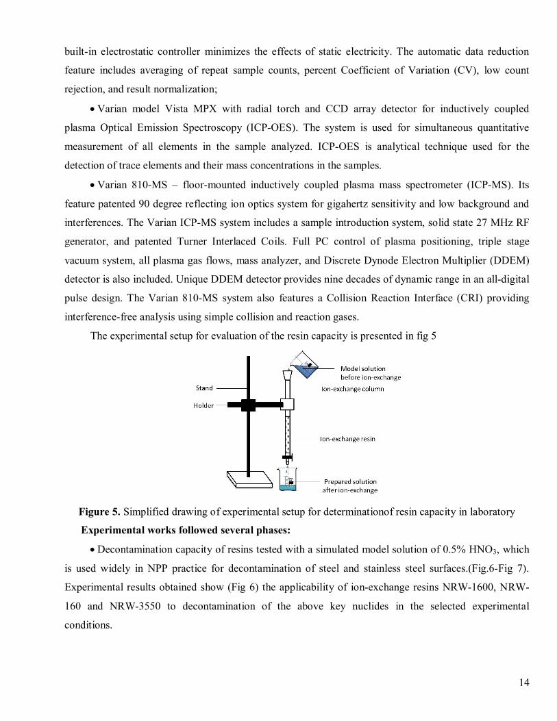
The experimental setup for evaluation of the resin capacity is presented in fig 5
Figure 5. Simplified drawing of experimental setup for determinationof resin capacity in laboratory
Experimental works followed several phases:
· Decontamination capacity of resins tested with a simulated model solution of 0.5% HNO3, which
is used widely in NPP practice for decontamination of steel and stainless steel surfaces.(Fig.6-Fig 7).
Experimental results obtained show (Fig 6) the applicability of ion-exchange resins NRW-1600, NRW-
160 and NRW-3550 to decontamination of the above key nuclides in the selected experimental
conditions.

15
Figure 6. Histogram presentation of DF of NRW1600, NRW160, NRW3550for 137Cs, 60Co, and 241Am
Resin Amberlite IR 120 presents a lower activity than the above tested resins.
Figure7. Histogram presentation of DF of AMBERLITE IR 120 Na and AMBERLITE IRA 410 Cl forCo, Fe, Ni and Sr
· Decontamination capacity of cation resin Amberlite-IR120 for specific decontaminants used inNPP practice
The following decontaminants were selected:
- 0.5% HNO3 - nitric acid is used for decontamination of steel components and stainless steel
surfaces.
- 10% H2C2O4 – oxalic acid is widely used for decontamination of wood and concrete.
- 3% NaOH – is used for decontamination of porcelain and many polymer materials, such as PE,
HDPE, PVC etc.
- Surfactant solution – most commonly used for decontamination of textile materials.
The contaminants were labelled with known amount of 90Sr, which is a beta-emitting radionuclide
with great contribution to the radioactivity of low-level nuclear wastes.
16
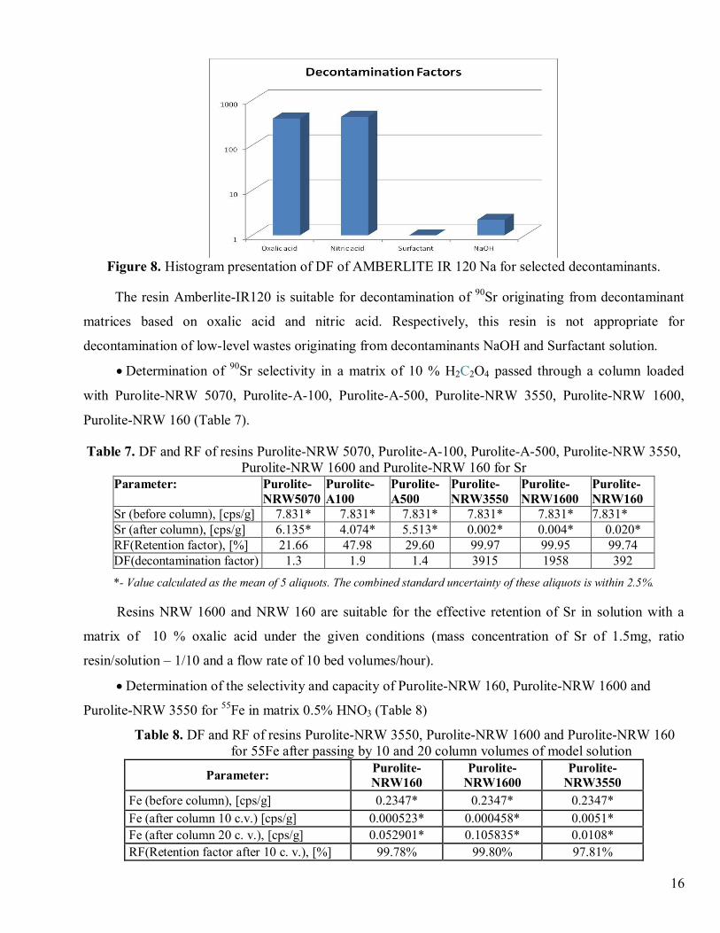
Figure 8. Histogram presentation of DF of AMBERLITE IR 120 Na for selected decontaminants.
The resin Amberlite-IR120 is suitable for decontamination of 90Sr originating from decontaminant
matrices based on oxalic acid and nitric acid. Respectively, this resin is not appropriate for
decontamination of low-level wastes originating from decontaminants NaOH and Surfactant solution.
· Determination of 90Sr selectivity in a matrix of 10 % H2C2O4 passed through a column loaded
with Purolite-NRW 5070, Purolite-A-100, Purolite-A-500, Purolite-NRW 3550, Purolite-NRW 1600,
Purolite-NRW 160 (Table 7).
Table 7. DF and RF of resins Purolite-NRW 5070, Purolite-A-100, Purolite-A-500, Purolite-NRW 3550,Purolite-NRW 1600 and Purolite-NRW 160 for Sr
Parameter: Purolite-NRW5070
Purolite-А100
Purolite-А500
Purolite-NRW3550
Purolite-NRW1600
Purolite-NRW160
Sr (before column), [cps/g] 7.831* 7.831* 7.831* 7.831* 7.831* 7.831*Sr (after column), [cps/g] 6.135* 4.074* 5.513* 0.002* 0.004* 0.020*RF(Retention factor), [%] 21.66 47.98 29.60 99.97 99.95 99.74DF(decontamination factor) 1.3 1.9 1.4 3915 1958 392
*- Value calculated as the mean of 5 aliquots. The combined standard uncertainty of these aliquots is within 2.5%.
Resins NRW 1600 and NRW 160 are suitable for the effective retention of Sr in solution with a
matrix of 10 % oxalic acid under the given conditions (mass concentration of Sr of 1.5mg, ratio
resin/solution – 1/10 and a flow rate of 10 bed volumes/hour).
· Determination of the selectivity and capacity of Purolite-NRW 160, Purolite-NRW 1600 and
Purolite-NRW 3550 for 55Fe in matrix 0.5% HNO3 (Table 8)
Table 8. DF and RF of resins Purolite-NRW 3550, Purolite-NRW 1600 and Purolite-NRW 160for 55Fe after passing by 10 and 20 column volumes of model solution
Parameter: Purolite-NRW160
Purolite-NRW1600
Purolite-NRW3550
Fe (before column), [cps/g] 0.2347* 0.2347* 0.2347*Fe (after column 10 c.v.) [cps/g] 0.000523* 0.000458* 0.0051*Fe (after column 20 c. v.), [cps/g] 0.052901* 0.105835* 0.0108*RF(Retention factor after 10 c. v.), [%] 99.78% 99.80% 97.81%
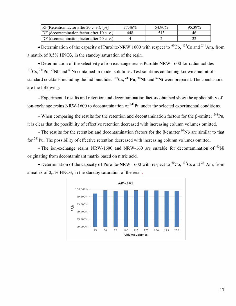
17
RF(Retention factor after 20 c. v.), [%] 77.46% 54.90% 95.39%DF (decontamination factor after 10 c. v.) 448 513 46DF (decontamination factor after 20 c. v.) 4 2 22
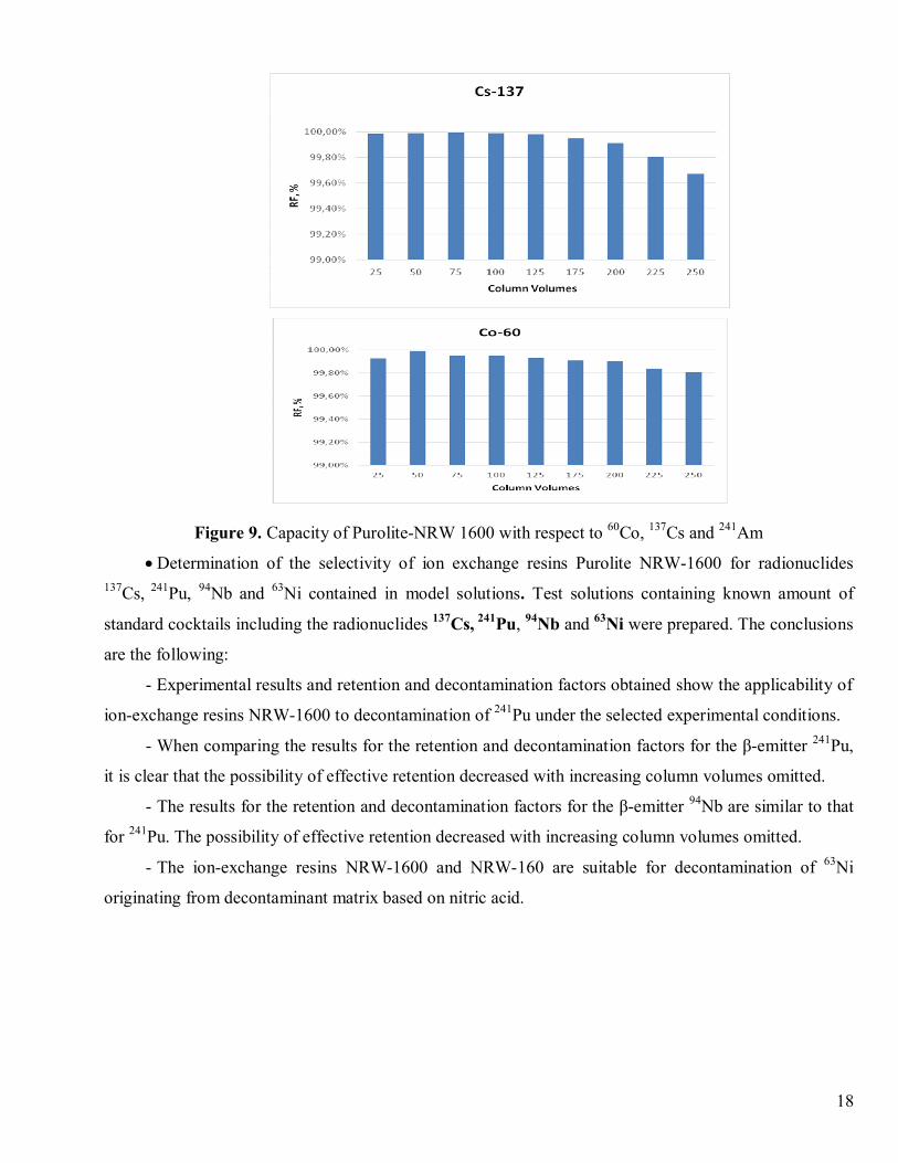
· Determination of the capacity of Purolite-NRW 1600 with respect to 60Co, 137Cs and 241Am, from
a matrix of 0,5% HNO3, in the standby saturation of the resin.
· Determination of the selectivity of ion exchange resins Purolite NRW-1600 for radionuclides137Cs, 241Pu, 94Nb and 63Ni contained in model solutions. Test solutions containing known amount of
standard cocktails including the radionuclides 137Cs, 241Pu, 94Nb and 63Ni were prepared. The conclusions
are the following:
- Experimental results and retention and decontamination factors obtained show the applicability of
ion-exchange resins NRW-1600 to decontamination of 241Pu under the selected experimental conditions.
- When comparing the results for the retention and decontamination factors for the β-emitter 241Pu,
it is clear that the possibility of effective retention decreased with increasing column volumes omitted.
- The results for the retention and decontamination factors for the β-emitter 94Nb are similar to that
for 241Pu. The possibility of effective retention decreased with increasing column volumes omitted.
- The ion-exchange resins NRW-1600 and NRW-160 are suitable for decontamination of 63Ni
originating from decontaminant matrix based on nitric acid.
· Determination of the capacity of Purolite-NRW 1600 with respect to 60Co, 137Cs and 241Am, from
a matrix of 0,5% HNO3, in the standby saturation of the resin.
18
Figure 9. Capacity of Purolite-NRW 1600 with respect to 60Co, 137Cs and 241Am
· Determination of the selectivity of ion exchange resins Purolite NRW-1600 for radionuclides137Cs, 241Pu, 94Nb and 63Ni contained in model solutions. Test solutions containing known amount of
standard cocktails including the radionuclides 137Cs, 241Pu, 94Nb and 63Ni were prepared. The conclusions
are the following:
- Experimental results and retention and decontamination factors obtained show the applicability of
ion-exchange resins NRW-1600 to decontamination of 241Pu under the selected experimental conditions.
- When comparing the results for the retention and decontamination factors for the β-emitter 241Pu,
it is clear that the possibility of effective retention decreased with increasing column volumes omitted.
- The results for the retention and decontamination factors for the β-emitter 94Nb are similar to that
for 241Pu. The possibility of effective retention decreased with increasing column volumes omitted.
- The ion-exchange resins NRW-1600 and NRW-160 are suitable for decontamination of 63Ni
originating from decontaminant matrix based on nitric acid.
19
0
100
200
300
400
500
600
700
800
900
1 3 5 7 9 11 13 15 17 19 21 23 25 27 29 31 33 35 37 39 41 43 45 47 49 51 53
Channel
Cou
nts
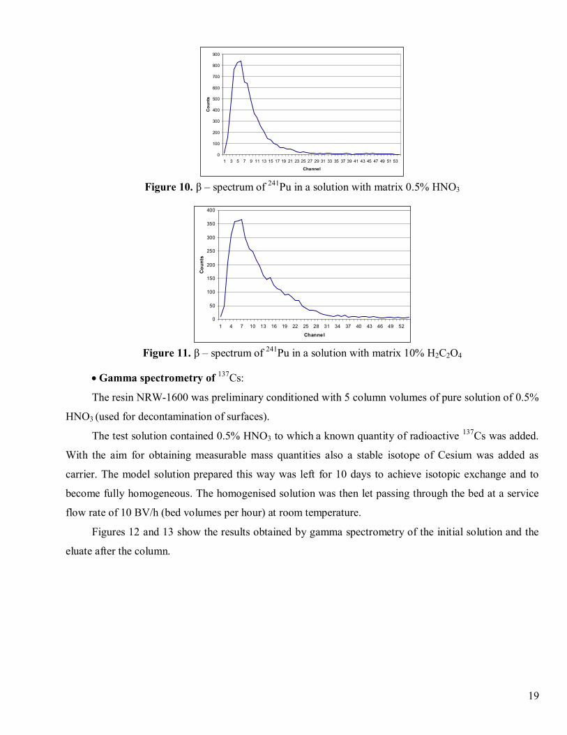
Figure 10. β – spectrum of 241Pu in a solution with matrix 0.5% HNO3
0
50
100
150
200
250
300
350
400
1 4 7 10 13 16 19 22 25 28 31 34 37 40 43 46 49 52
Channel
Cou
nts
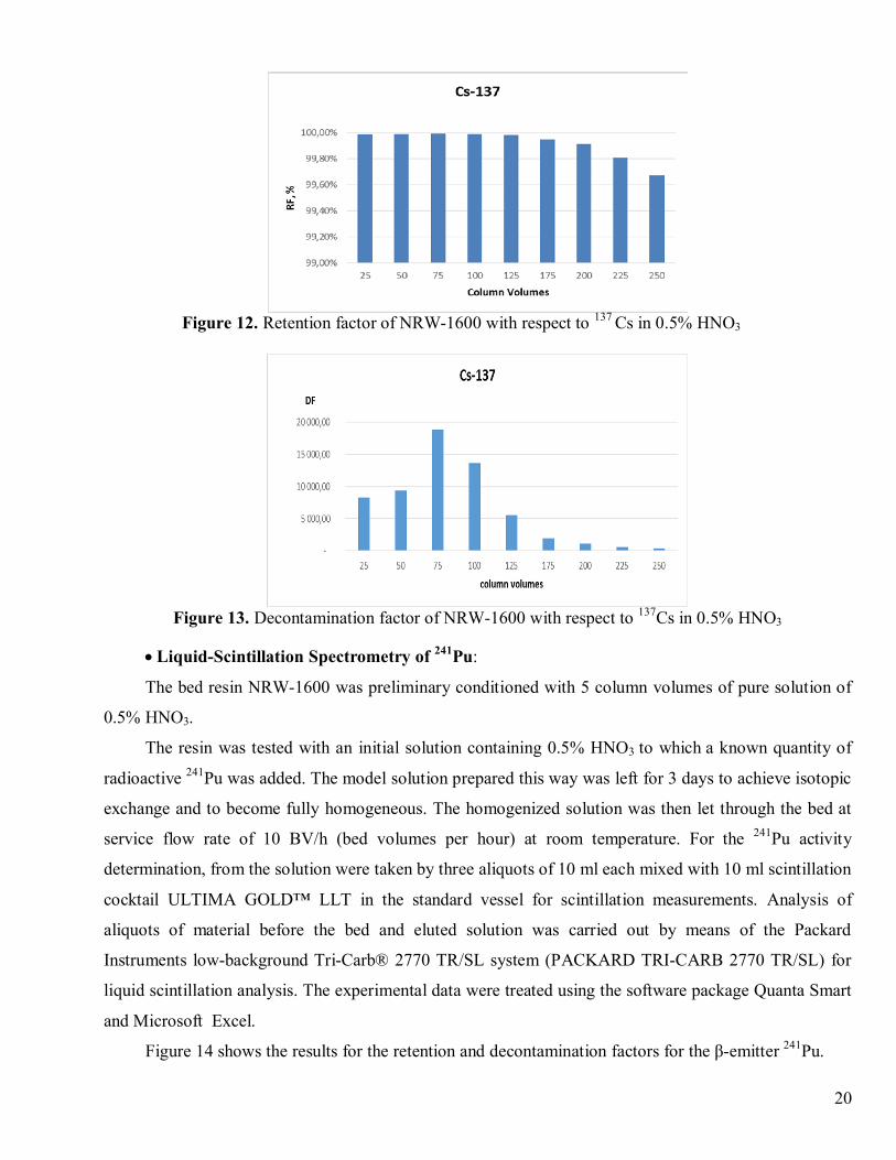
Figure 11. β – spectrum of 241Pu in a solution with matrix 10% H2C2O4
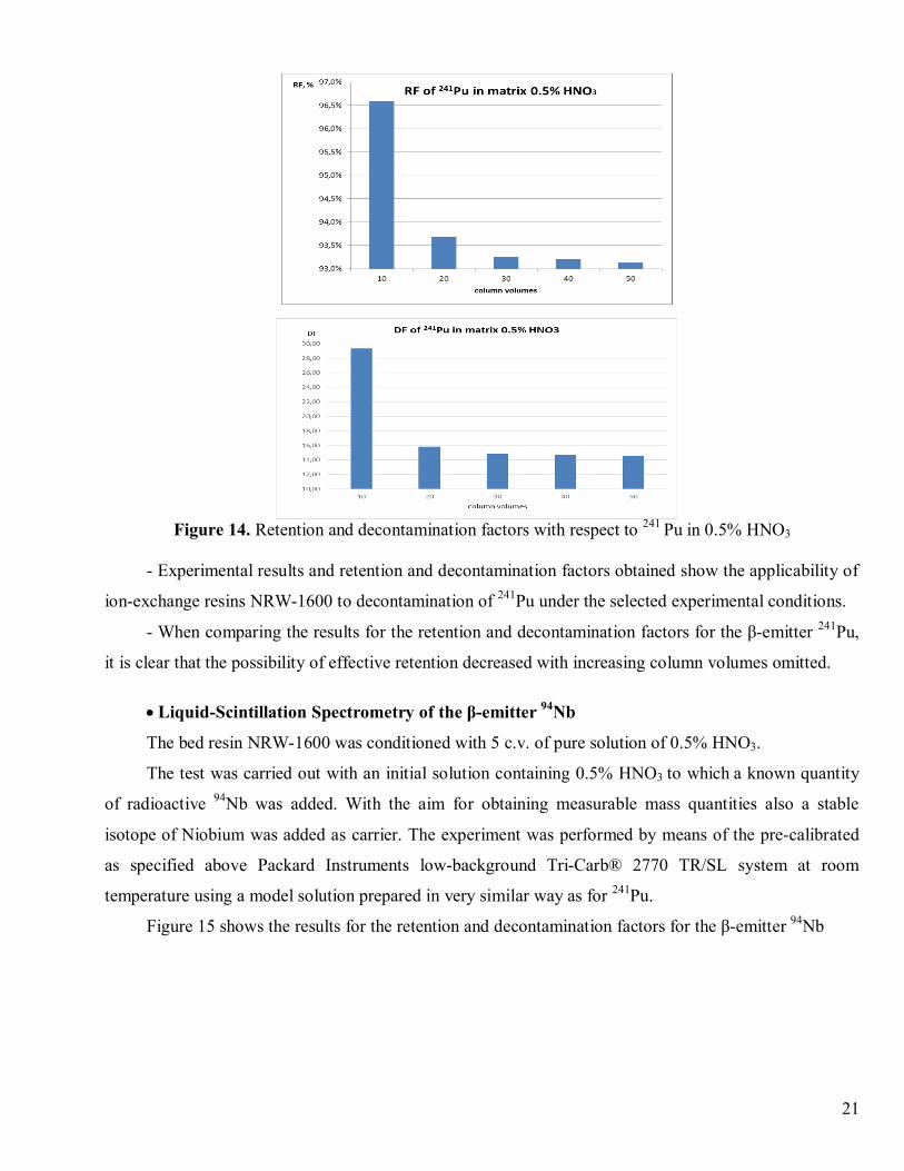
· Gamma spectrometry of 137Cs:
The resin NRW-1600 was preliminary conditioned with 5 column volumes of pure solution of 0.5%
HNO3 (used for decontamination of surfaces).
The test solution contained 0.5% HNO3 to which a known quantity of radioactive 137Cs was added.
With the aim for obtaining measurable mass quantities also a stable isotope of Cesium was added as
carrier. The model solution prepared this way was left for 10 days to achieve isotopic exchange and to
become fully homogeneous. The homogenised solution was then let passing through the bed at a service
flow rate of 10 BV/h (bed volumes per hour) at room temperature.
Figures 12 and 13 show the results obtained by gamma spectrometry of the initial solution and the
eluate after the column.
20
Figure 12. Retention factor of NRW-1600 with respect to 137 Cs in 0.5% HNO3
Figure 13. Decontamination factor of NRW-1600 with respect to 137Cs in 0.5% HNO3
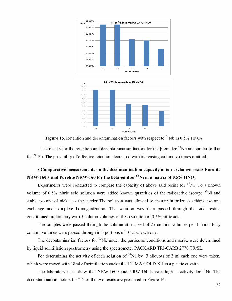
· Liquid-Scintillation Spectrometry of 241Pu:
The bed resin NRW-1600 was preliminary conditioned with 5 column volumes of pure solution of
0.5% HNO3.
The resin was tested with an initial solution containing 0.5% HNO3 to which a known quantity of
radioactive 241Pu was added. The model solution prepared this way was left for 3 days to achieve isotopic
exchange and to become fully homogeneous. The homogenized solution was then let through the bed at
service flow rate of 10 BV/h (bed volumes per hour) at room temperature. For the 241Pu activity
determination, from the solution were taken by three aliquots of 10 ml each mixed with 10 ml scintillation
cocktail ULTIMA GOLD™ LLT in the standard vessel for scintillation measurements. Analysis of
aliquots of material before the bed and eluted solution was carried out by means of the Packard
Instruments low-background Tri-Carb® 2770 TR/SL system (PACKARD TRI-CARB 2770 TR/SL) for
liquid scintillation analysis. The experimental data were treated using the software package Quanta Smart
and Microsoft Excel.
Figure 14 shows the results for the retention and decontamination factors for the β-emitter 241Pu.
21
Figure 14. Retention and decontamination factors with respect to 241 Pu in 0.5% HNO3
- Experimental results and retention and decontamination factors obtained show the applicability of
ion-exchange resins NRW-1600 to decontamination of 241Pu under the selected experimental conditions.
- When comparing the results for the retention and decontamination factors for the β-emitter 241Pu,
it is clear that the possibility of effective retention decreased with increasing column volumes omitted.
· Liquid-Scintillation Spectrometry of the β-emitter 94Nb
The bed resin NRW-1600 was conditioned with 5 c.v. of pure solution of 0.5% HNO3.
The test was carried out with an initial solution containing 0.5% HNO3 to which a known quantity
of radioactive 94Nb was added. With the aim for obtaining measurable mass quantities also a stable
isotope of Niobium was added as carrier. The experiment was performed by means of the pre-calibrated
as specified above Packard Instruments low-background Tri-Carb® 2770 TR/SL system at room
temperature using a model solution prepared in very similar way as for 241Pu.
Figure 15 shows the results for the retention and decontamination factors for the β-emitter 94Nb
22
Figure 15. Retention and decontamination factors with respect to 94Nb in 0.5% HNO3
The results for the retention and decontamination factors for the β-emitter 94Nb are similar to that
for 241Pu. The possibility of effective retention decreased with increasing column volumes omitted.
· Comparative measurements on the decontamination capacity of ion-exchange resins Purolite
NRW-1600 and Purolite NRW-160 for the beta-emitter 63Ni in a matrix of 0.5% HNO3
Experiments were conducted to compare the capacity of above said resins for 63Ni. To a known
volume of 0.5% nitric acid solution were added known quantities of the radioactive isotope 63Ni and
stable isotope of nickel as the carrier The solution was allowed to mature in order to achieve isotope
exchange and complete homogenization. The solution was then passed through the said resins,
conditioned preliminary with 5 column volumes of fresh solution of 0.5% nitric acid.
The samples were passed through the column at a speed of 25 column volumes per 1 hour. Fifty
column volumes were passed through in 5 portions of 10 c. v. each one.
The decontamination factors for 63Ni, under the particular conditions and matrix, were determined
by liquid scintillation spectrometry using the spectrometer PACKARD TRI-CARB 2770 TR/SL.
For determining the activity of each solution of 63Ni, by 3 aliquots of 2 ml each one were taken,
which were mixed with 18ml of scintillation cocktail ULTIMA GOLD XR in a plastic cuvette.
The laboratory tests show that NRW-1600 and NRW-160 have a high selectivity for 63Ni. The
decontamination factors for 63N of the two resins are presented in Figure 16.
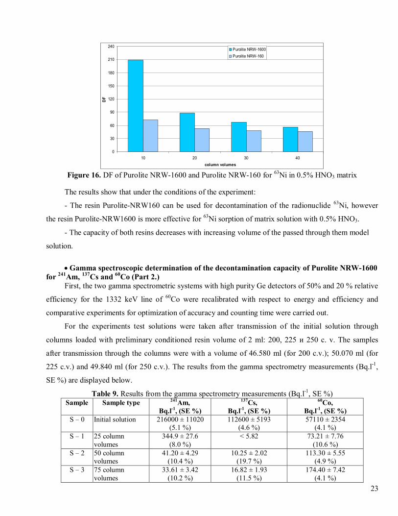
23
0
30
60
90
120
150
180
210
240
10 20 30 40column volumes
DF
Purolite NRW-1600Purolite NRW-160
Figure 16. DF of Purolite NRW-1600 and Purolite NRW-160 for 63Ni in 0.5% HNO3 matrix
The results show that under the conditions of the experiment:
- The resin Purolite-NRW160 can be used for decontamination of the radionuclide 63Ni, however
the resin Purolite-NRW1600 is more effective for 63Ni sorption of matrix solution with 0.5% HNO3.
- The capacity of both resins decreases with increasing volume of the passed through them model
solution.
· Gamma spectroscopic determination of the decontamination capacity of Purolite NRW-1600for 241Am, 137Cs and 60Co (Part 2.)
First, the two gamma spectrometric systems with high purity Ge detectors of 50% and 20 % relative
efficiency for the 1332 keV line of 60Co were recalibrated with respect to energy and efficiency and
comparative experiments for optimization of accuracy and counting time were carried out.
For the experiments test solutions were taken after transmission of the initial solution through
columns loaded with preliminary conditioned resin volume of 2 ml: 200, 225 и 250 c. v. The samples
after transmission through the columns were with a volume of 46.580 ml (for 200 c.v.); 50.070 ml (for
225 c.v.) and 49.840 ml (for 250 c.v.). The results from the gamma spectrometry measurements (Bq.l-1,
SE %) are displayed below.
Table 9. Results from the gamma spectrometry measurements (Bq.l-1, SE %)Sample Sample type 241Am,
Bq.l-1, (SE %)137Cs,
Bq.l-1, (SE %)60Co,
Bq.l-1, (SE %)S – 0 Initial solution 216000 ± 11020
(5.1 %)112600 ± 5193
(4.6 %)57110 ± 2354
(4.1 %)S – 1 25 column
volumes344.9 ± 27.6
(8.0 %)< 5.82 73.21 ± 7.76
(10.6 %)S – 2 50 column
volumes41.20 ± 4.29
(10.4 %)10.25 ± 2.02
(19.7 %)113.30 ± 5.55
(4.9 %)S – 3 75 column
volumes33.61 ± 3.42
(10.2 %)16.82 ± 1.93
(11.5 %)174.40 ± 7.42
(4.1 %)
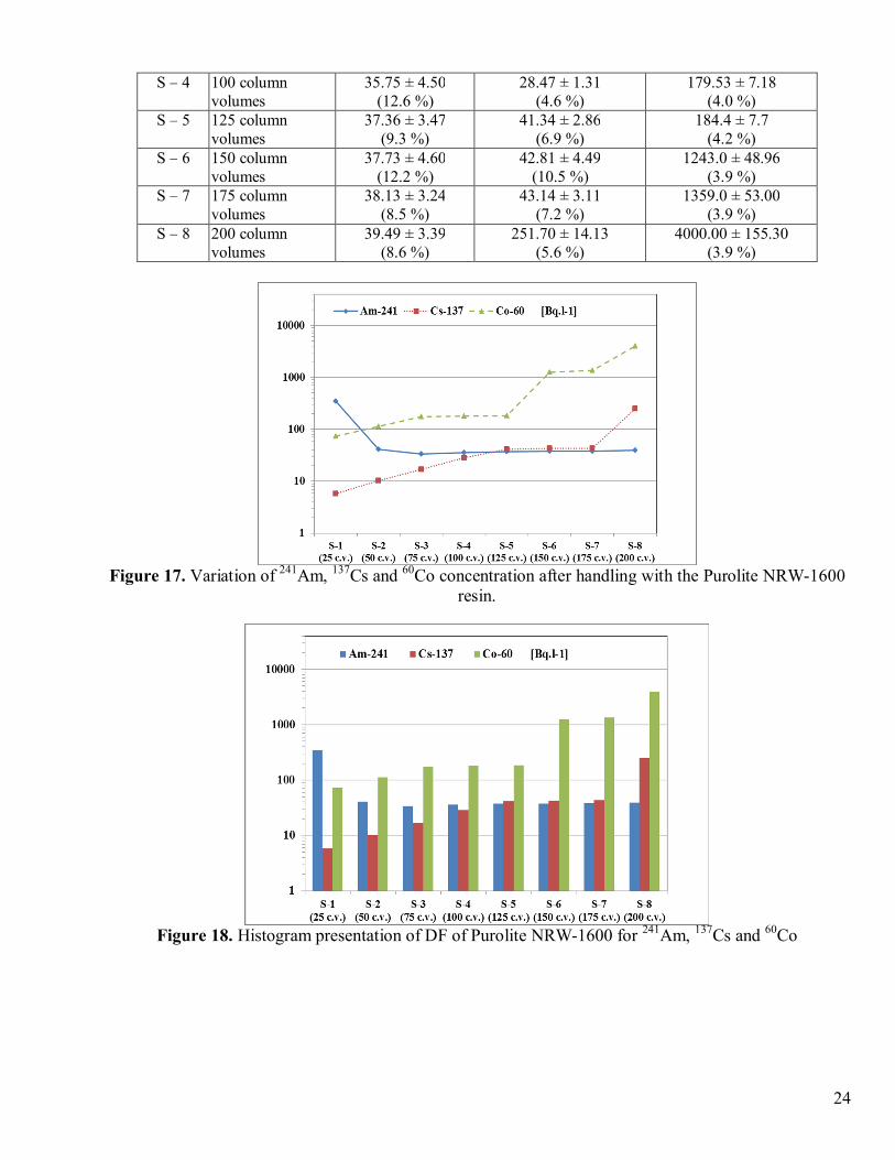
24
S – 4 100 columnvolumes
35.75 ± 4.50(12.6 %)
28.47 ± 1.31(4.6 %)
179.53 ± 7.18(4.0 %)
S – 5 125 columnvolumes
37.36 ± 3.47(9.3 %)
41.34 ± 2.86(6.9 %)
184.4 ± 7.7(4.2 %)
S – 6 150 columnvolumes
37.73 ± 4.60(12.2 %)
42.81 ± 4.49(10.5 %)
1243.0 ± 48.96(3.9 %)
S – 7 175 columnvolumes
38.13 ± 3.24(8.5 %)
43.14 ± 3.11(7.2 %)
1359.0 ± 53.00(3.9 %)
S – 8 200 columnvolumes
39.49 ± 3.39(8.6 %)
251.70 ± 14.13(5.6 %)
4000.00 ± 155.30(3.9 %)
Figure 17. Variation of 241Am, 137Cs and 60Co concentration after handling with the Purolite NRW-1600resin.
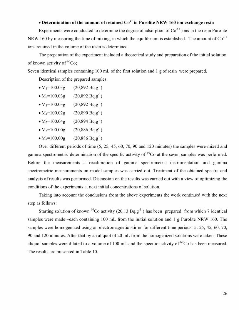
Figure 18. Histogram presentation of DF of Purolite NRW-1600 for 241Am, 137Cs and 60Co

25
Figure 19. Decontamination factors (DF) of ion-exchange resin Purolite NRW-1600 for radionuclides241Am, 137Cs and 60Co.
Figure 20. Histogram presentation of DF of Purolite NRW-1600 for 241Am, 137Cs and 60Co
The obtained removed activity data show high percentage of retention of analyzed radionuclides
(241Am, 137Cs, 60Co). This result is confirmed also by the for the decontamination factors (DF) data. For
decontamination of the radionuclide 63Ni the resin Purolite-NRW160 can also be used, however the resin
Purolite-NRW1600 is more effective for 63Ni sorption of matrix solution with 0.5% HNO3.
Therefore, it can be concluded that under the conditions of present experiments the resin Purolite
NRW-1600 is good cleaner for liquid radioactive wastes containing radionuclides such as 241Am, 137Cs,60Co and 63Ni.
26
· Determination of the amount of retained Co2+ in Purolite NRW 160 ion exchange resin
Experiments were conducted to determine the degree of adsorption of Co2 + ions in the resin Purolite
NRW 160 by measuring the time of mixing, in which the equilibrium is established. The amount of Co2 +
ions retained in the volume of the resin is determined.
The preparation of the experiment included a theoretical study and preparation of the initial solution
of known activity of 60Co;
Seven identical samples containing 100 mL of the first solution and 1 g of resin were prepared.
Description of the prepared samples:
· М1=100.03g (20,892 Bq.g-1)
· М2=100.03g (20,892 Bq.g-1)
· М3=100.03g (20,892 Bq.g-1)
· М4=100.02g (20,890 Bq.g-1)
· М5=100.04g (20,894 Bq.g-1)
· М6=100.00g (20,886 Bq.g-1)
· М7=100.00g (20,886 Bq.g-1)
Over different periods of time (5, 25, 45, 60, 70, 90 and 120 minutes) the samples were mixed and
gamma spectrometric determination of the specific activity of 60Co at the seven samples was performed.
Before the measurements a recalibration of gamma spectrometric instrumentation and gamma
spectrometric measurements on model samples was carried out. Treatment of the obtained spectra and
analysis of results was performed. Discussion on the results was carried out with a view of optimizing the
conditions of the experiments at next initial concentrations of solution.
Taking into account the conclusions from the above experiments the work continued with the next
step as follows:
Starting solution of known 60Co activity (20.13 Bq.g-1 ) has been prepared from which 7 identical
samples were made –each containing 100 mL from the initial solution and 1 g Purolite NRW 160. The
samples were homogenized using an electromagnetic stirrer for different time periods: 5, 25, 45, 60, 70,
90 and 120 minutes. After that by an aliquot of 20 mL from the homogenized solutions were taken. These
aliquot samples were diluted to a volume of 100 mL and the specific activity of 60Co has been measured.
The results are presented in Table 10.
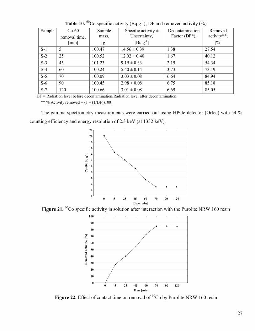
27
Table 10. 60Co specific activity (Bq.g-1), DF and removed activity (%)
DF = Radiation level before decontamination/Radiation level after decontamination.** % Activity removed = (1 – (1/DF))100
The gamma spectrometry measurements were carried out using HPGe detector (Ortec) with 54 %
counting efficiency and energy resolution of 2.3 keV (at 1332 keV).
0 5 25 45 60 70 90 120Time [min]
0
2
4
6
8
10
12
14
16
18
20
22
Co-
60 [B
q.g-1
]
Figure 21. 60Co specific activity in solution after interaction with the Purolite NRW 160 resin
0 5 25 45 60 70 90 120Time [min]
0
10
20
30
40
50
60
70
80
90
100
Rem
oved
act
ivity
, [%
]
Figure 22. Effect of contact time on removal of 60Co by Purolite NRW 160 resin
Sample Co-60removal time,
[min]
Samplemass,
[g]
Specific activity ±Uncertainty,
[Bq.g-1]
DecontaminationFactor (DF*),
Removedactivity**,
[%]S-1 5 100.47 14.56 ± 0.39 1.38 27.54S-2 25 100.52 12.02 ± 0.40 1.67 40.12S-3 45 101.23 9.19 ± 0.33 2.19 54.34S-4 60 100.24 5.40 ± 0.14 3.73 73.19S-5 70 100.09 3.03 ± 0.08 6.64 84.94S-6 90 100.45 2.98 ± 0.08 6.75 85.18S-7 120 100.66 3.01 ± 0.08 6.69 85.05
28
· Determination of the amount of retained Co2+ in Purolite NRW 160 ion exchange resin by
means of spectrophotometry
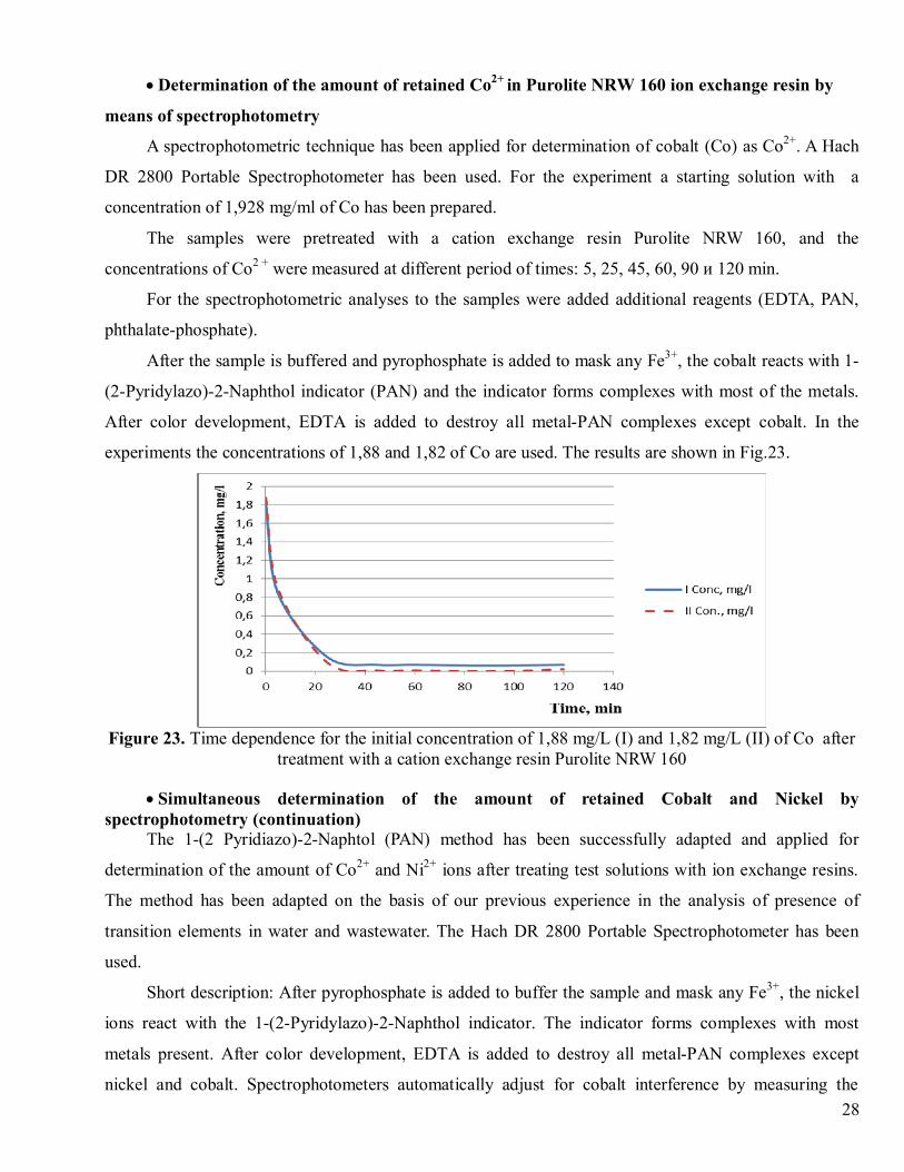
A spectrophotometric technique has been applied for determination of cobalt (Co) as Co2+. A Hach
DR 2800 Portable Spectrophotometer has been used. For the experiment a starting solution with a
concentration of 1,928 mg/ml of Co has been prepared.
The samples were pretreated with a cation exchange resin Purolite NRW 160, and the
concentrations of Co2 + were measured at different period of times: 5, 25, 45, 60, 90 и 120 min.
For the spectrophotometric analyses to the samples were added additional reagents (EDTA, PAN,
phthalate-phosphate).
After the sample is buffered and pyrophosphate is added to mask any Fe3+, the cobalt reacts with 1-
(2-Pyridylazo)-2-Naphthol indicator (PAN) and the indicator forms complexes with most of the metals.
After color development, EDTA is added to destroy all metal-PAN complexes except cobalt. In the
experiments the concentrations of 1,88 and 1,82 of Co are used. The results are shown in Fig.23.
Figure 23. Time dependence for the initial concentration of 1,88 mg/L (I) and 1,82 mg/L (II) of Co aftertreatment with a cation exchange resin Purolite NRW 160
· Simultaneous determination of the amount of retained Cobalt and Nickel byspectrophotometry (continuation)
The 1-(2 Pyridiazo)-2-Naphtol (PAN) method has been successfully adapted and applied for
determination of the amount of Co2+ and Ni2+ ions after treating test solutions with ion exchange resins.
The method has been adapted on the basis of our previous experience in the analysis of presence of
transition elements in water and wastewater. The Hach DR 2800 Portable Spectrophotometer has been
used.
Short description: After pyrophosphate is added to buffer the sample and mask any Fe3+, the nickel
ions react with the 1-(2-Pyridylazo)-2-Naphthol indicator. The indicator forms complexes with most
metals present. After color development, EDTA is added to destroy all metal-PAN complexes except
nickel and cobalt. Spectrophotometers automatically adjust for cobalt interference by measuring the
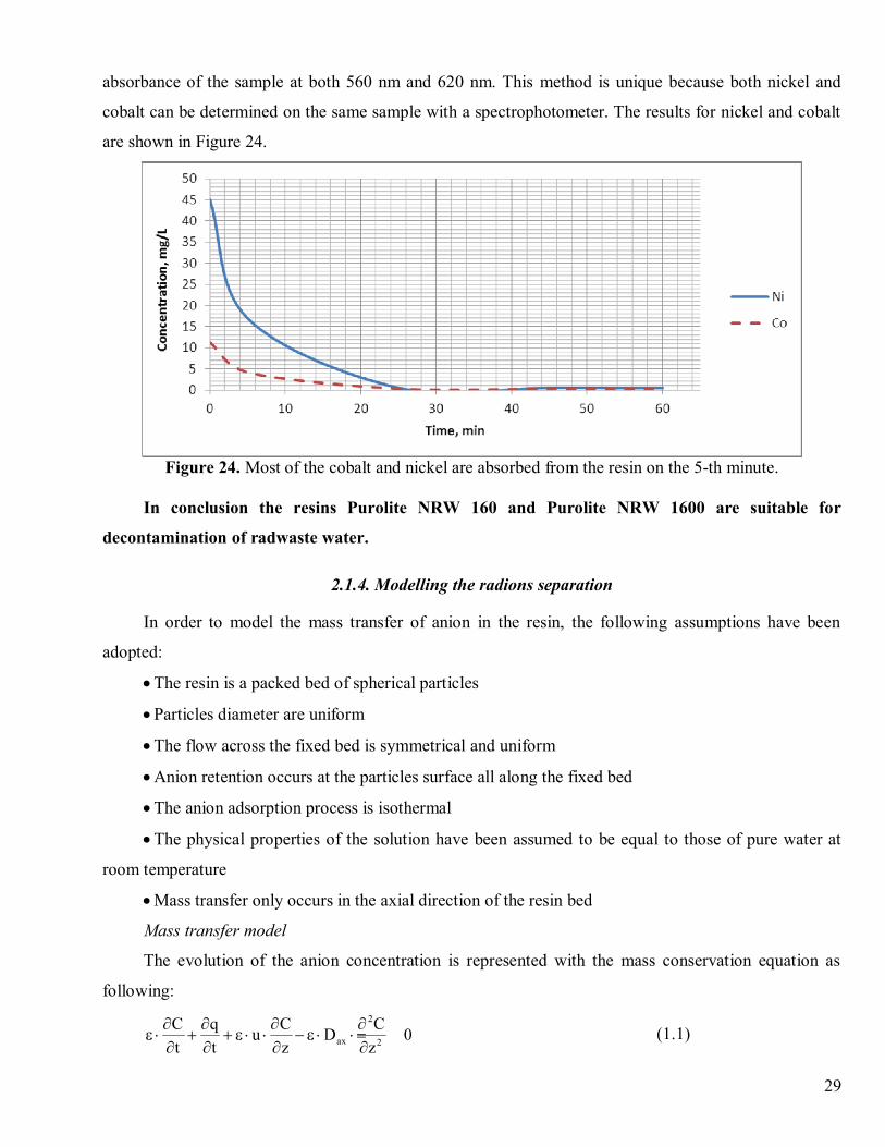
29
absorbance of the sample at both 560 nm and 620 nm. This method is unique because both nickel and
cobalt can be determined on the same sample with a spectrophotometer. The results for nickel and cobalt
are shown in Figure 24.
Figure 24. Most of the cobalt and nickel are absorbed from the resin on the 5-th minute.
In conclusion the resins Purolite NRW 160 and Purolite NRW 1600 are suitable for
decontamination of radwaste water.
2.1.4. Modelling the radions separation
In order to model the mass transfer of anion in the resin, the following assumptions have been
adopted:
· The resin is a packed bed of spherical particles
· Particles diameter are uniform
· The flow across the fixed bed is symmetrical and uniform
· Anion retention occurs at the particles surface all along the fixed bed
· The anion adsorption process is isothermal
· The physical properties of the solution have been assumed to be equal to those of pure water at
room temperature
· Mass transfer only occurs in the axial direction of the resin bed
Mass transfer model
The evolution of the anion concentration is represented with the mass conservation equation as
following:2
ax 2
C q C Cu D 0t t z z
¶ ¶ ¶ ¶e × + + e × × - e × × =
¶ ¶ ¶ ¶(1.1)

30
In this equation, the first two terms represent accumulation in the pores and at the particles surface
(due to adsorption), whereas the two last terms take into account convective and diffusional mass
transport in the bed axial direction.
The variation of the anion concentration C in the radial direction of the bed has been neglected
because mass transfer in this direction is faster than in the path of the length of the bed Lp given by:
Lp » tax×L (1.2)
Where tax, is the tortuosity in the axial direction set equal to 1.4 for a bed of spherical particles [7]
and L is the bed height.
This has been validated by calculating the time to cross the column diameter (dc/kc) and comparing
it with the time to cross the bed length (Lp/u) [8].
p c
c
L du k
> (1.3)
The local mass transfer coefficient kc has been evaluated with the relationship:31
axg
axc ScRe03.164
dDk ú
û
ùêë
é××÷
øö
çèæ
e+×= (1.4)
with:
h×e×r×
=ud
Re g (1.5)
and
axax D
Sc×rh
= (1.6)
The velocity of flow in the pores is given by:
2c
4 Fud×
=p × × e
(1.7)
where F is the feed volumetric flow rate, dc column diameter and e the bed porosity.
The concentration of the ion in the adsorbed phase is given by Langmuir equation:
am
a
K Cq q1 K C
×= ×
+ ×(1.8)
where Ka is the equilibrium constant and qm is the resin capacity.
The initial and boundary conditions have been set as below:
At t = 0, for z ≥ 0 , C = 0
At z = 0 for t > 0, F axCu C u C Dz
¶× = × - ×
31
At z = L for t > 0, C 0z
¶=
Mathematical resolution
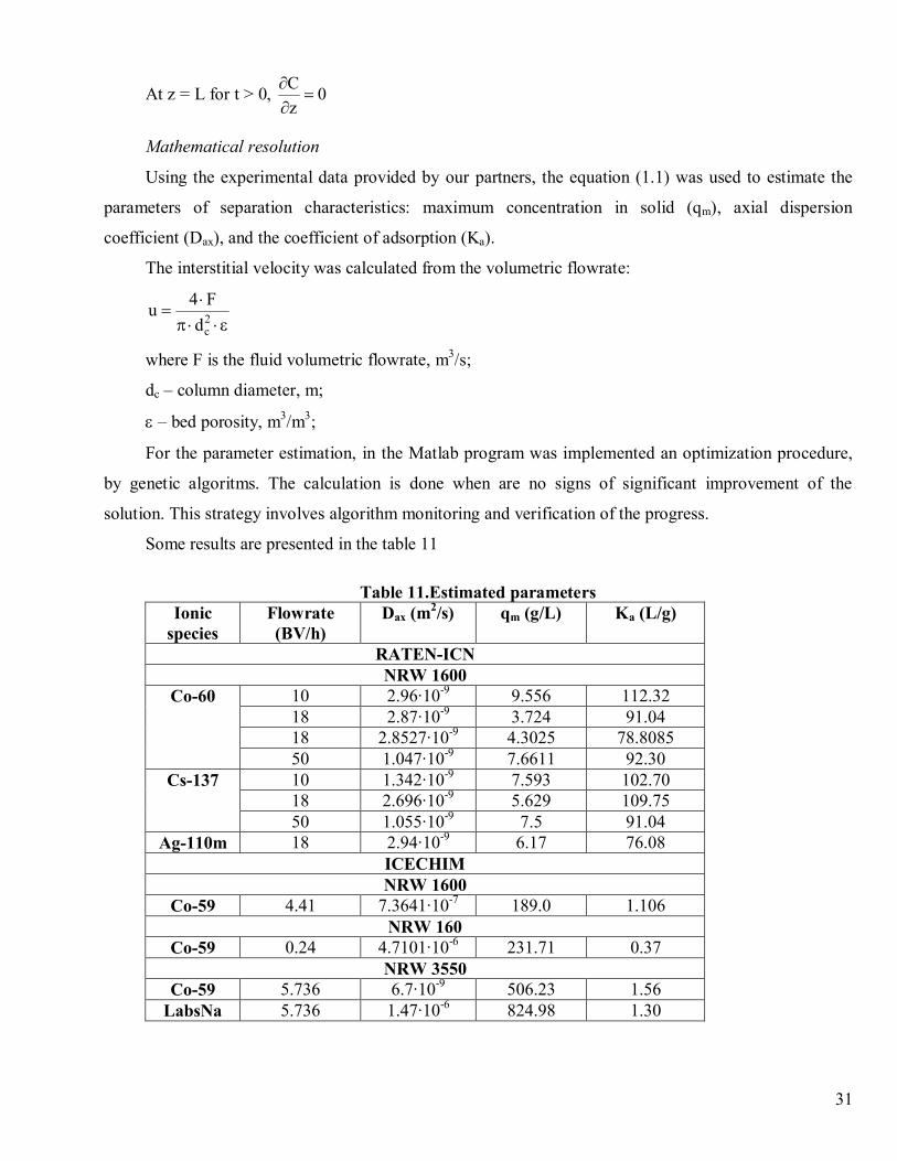
Using the experimental data provided by our partners, the equation (1.1) was used to estimate the
parameters of separation characteristics: maximum concentration in solid (qm), axial dispersion
coefficient (Dax), and the coefficient of adsorption (Ka).
The interstitial velocity was calculated from the volumetric flowrate:
2c
4 Fud×
=p × ×e
where F is the fluid volumetric flowrate, m3/s;
dc – column diameter, m;
e – bed porosity, m3/m3;
For the parameter estimation, in the Matlab program was implemented an optimization procedure,
by genetic algoritms. The calculation is done when are no signs of significant improvement of the
solution. This strategy involves algorithm monitoring and verification of the progress.
Some results are presented in the table 11
Table 11.Estimated parametersIonic
speciesFlowrate(BV/h)
Dax (m2/s) qm (g/L) Ka (L/g)
RATEN-ICNNRW 1600
Co-60 10 2.96·10-9 9.556 112.3218 2.87·10-9 3.724 91.0418 2.8527·10-9 4.3025 78.808550 1.047·10-9 7.6611 92.30
Cs-137 10 1.342·10-9 7.593 102.7018 2.696·10-9 5.629 109.7550 1.055·10-9 7.5 91.04
Ag-110m 18 2.94·10-9 6.17 76.08ICECHIMNRW 1600
Co-59 4.41 7.3641·10-7 189.0 1.106NRW 160
Co-59 0.24 4.7101·10-6 231.71 0.37NRW 3550
Co-59 5.736 6.7·10-9 506.23 1.56LabsNa 5.736 1.47·10-6 824.98 1.30
32
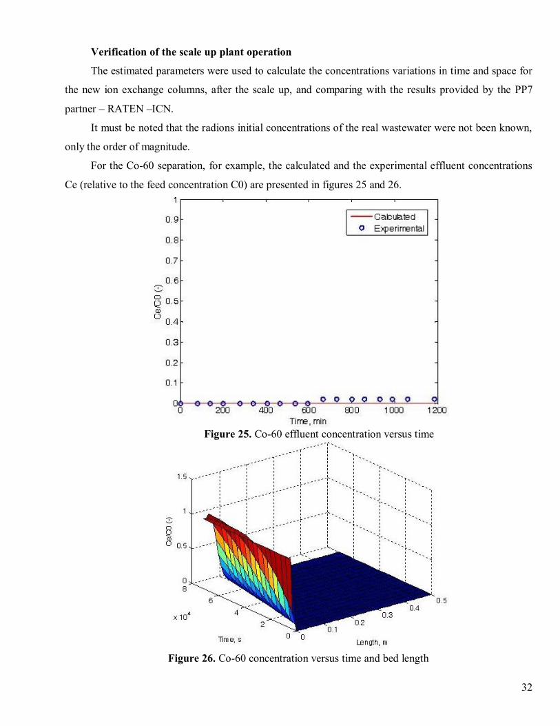
Verification of the scale up plant operation
The estimated parameters were used to calculate the concentrations variations in time and space for
the new ion exchange columns, after the scale up, and comparing with the results provided by the PP7
partner – RATEN –ICN.
It must be noted that the radions initial concentrations of the real wastewater were not been known,
only the order of magnitude.
For the Co-60 separation, for example, the calculated and the experimental effluent concentrations
Ce (relative to the feed concentration C0) are presented in figures 25 and 26.
Figure 25. Co-60 effluent concentration versus time
Figure 26. Co-60 concentration versus time and bed length
33
It can be concluded that for this specific radwaste sample the bed volume was overestimated, an
important length of the bed remaining unused after 1 day of operation and can be used for future
treatments of other radwaste quantities.
2.2 Pilot scale testing of the decontamination process of radioactive wastewater from Cernavoda
NPP
2.2.1 Ion exchange resins used within experiments
To determine the type of ion exchangers that can be used successfully to treat aqueous radioactive
waste from Cernavoda NPP were recommended the ion exchanger pairs Purolite NRW160 + Purolite
NRW5050 and PuroliteNRW1600 + Purolite NRW5050, and the mixed bed resin Purolite NRW3550.
For pilot scale tests has been selected pair Purolite NRW1600 + Purolite NRW5050, combination that led
to the best results both to the radioactive species retention, and to the retention of the surfactants present
in aqueous radioactive waste arising from the decontamination processes.
2.2.2.Aqueous radioactive waste processed
Pilot-scale experiments were performed using liquid radioactive waste from Cernavoda NPP.
The radioactivity of the liquid waste processed at pilot scale is governed mainly by 137Cs, 134Cs,60Co, 110mAg, 125Sb, 95Zr, 95Nb, 3H and to smaller extent by 54Mn, 144Ce, 113Sn, 106Ru, 46Sc and 51Cr. After
filtration of suspended solids, 60Co, 134,137Cs, 54Mn, 95Zr, 95Nb and 3H were detected into aqueous
radioactive waste and the global gamma activity level was ~103 Bq/l.
The H-3 is not removed by ion exchange.
2.2.3 Methods and apparatus
To evaluate the effectiveness of the treatment process were determined: radioactive composition,
conductivity, pH and total dissolved salts content (TDS). Analyses were performed for the initial waste
(influent) and for elute (effluent).
The radioactive composition of aqueous radioactive waste was performed by measurement of
gamma emitting radionuclides concentrations with a high resolution spectrometer composed of a HPGe
detector with 25% relative efficiency, a low background shielding and a Canberra spectrometric analyzer,
model InSpector. The analysis software was GENIE-2000 from Canberra. The spectrometer was energy
and efficiency calibrated in the range 60 keV – 1500 keV, by considering all counting geometries used in
the experiments. The nuclear properties values used for data reduction were gathered from the original
generic library of the software GENIE 2000 v. 1.2.
34
The pH, conductivity and TDS measurement was performed with a Mettler Toledo multiparameter
device.
Analyses were performed for the initial waste (influent) and for effluents which must be discharged.
2.2.4 Test description
Pilot-scale test has treated 1.2 m3 aqueous radioactive waste from Cernavoda NPP. After separation
of the organic phase, settling and filtering suspension, the wastewater is treated by ion exchange. The ion
exchange resins used were cationite Purolite NRW1600 and anionite Purolite NRW5050.
The effluent is collected in containers with a capacity of 130 liters. At intervals of 60 minutes they
were determined, on fractions of effluent, pH, conductivity, gamma emitting radionuclides concentration
and tritium concentration. Effluent monitoring results of chemically and radioactively will indicate when
the resin is spent.
At the end of the test, representative effluent samples were collected; their physico-chemical
parameters were analyzed and were determined concentrations of tritium and gamma emitting
radionuclides.
The experimental conditions of tests at pilot scale performed were:
- dynamic experiment (column)
- batch operation (8 h daily)
- descendent flow (gravitational)
- fixed bed
- ambient temperature (20±2°C).
The characteristics of cationit column (Purolite NRW1600) were:
- Di = 160 mm
- Hcoloana = 800 mm
- hlq.col. = 640 ± 10 mm
- hpat = 500 mm
- Vpat = 10 L.
The characteristics of anionit column (Purolite NRW5050) were:
- Di = 160 mm
- Hcoloana = 800 mm
- hlq.col. = 640 ± 10 mm
- hpat = 300 mm
- Vpat = 6 L.
35
The test was performed at 10 BV/h flow rate for anionit and 6 BV/h flow rate for cationit. The
influent characteristics were pH = 6.56; conductivity = 0.226 mS/cm; TDS = 0.108 g/l.
Effluent monitoring
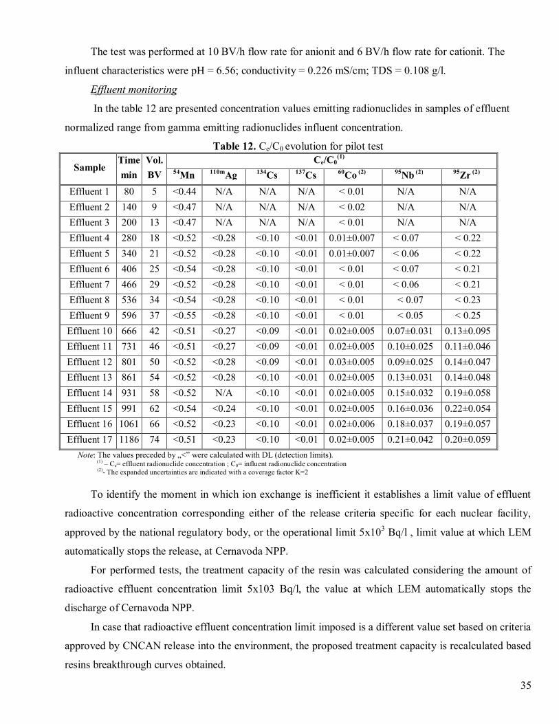
In the table 12 are presented concentration values emitting radionuclides in samples of effluent
normalized range from gamma emitting radionuclides influent concentration.
Table 12. Ce/C0 evolution for pilot test
SampleTimemin
Vol.BV
Ce/C0(1)
54Mn 110mAg 134Cs 137Cs 60Co (2) 95Nb (2) 95Zr (2)
Effluent 1 80 5 <0.44 N/A N/A N/A < 0.01 N/A N/AEffluent 2 140 9 <0.47 N/A N/A N/A < 0.02 N/A N/AEffluent 3 200 13 <0.47 N/A N/A N/A < 0.01 N/A N/AEffluent 4 280 18 <0.52 <0.28 <0.10 <0.01 0.01±0.007 < 0.07 < 0.22Effluent 5 340 21 <0.52 <0.28 <0.10 <0.01 0.01±0.007 < 0.06 < 0.22Effluent 6 406 25 <0.54 <0.28 <0.10 <0.01 < 0.01 < 0.07 < 0.21Effluent 7 466 29 <0.52 <0.28 <0.10 <0.01 < 0.01 < 0.06 < 0.21Effluent 8 536 34 <0.54 <0.28 <0.10 <0.01 < 0.01 < 0.07 < 0.23Effluent 9 596 37 <0.55 <0.28 <0.10 <0.01 < 0.01 < 0.05 < 0.25Effluent 10 666 42 <0.51 <0.27 <0.09 <0.01 0.02±0.005 0.07±0.031 0.13±0.095Effluent 11 731 46 <0.51 <0.27 <0.09 <0.01 0.02±0.005 0.10±0.025 0.11±0.046Effluent 12 801 50 <0.52 <0.28 <0.09 <0.01 0.03±0.005 0.09±0.025 0.14±0.047Effluent 13 861 54 <0.52 <0.28 <0.10 <0.01 0.02±0.005 0.13±0.031 0.14±0.048Effluent 14 931 58 <0.52 N/A <0.10 <0.01 0.02±0.005 0.15±0.032 0.19±0.058Effluent 15 991 62 <0.54 <0.24 <0.10 <0.01 0.02±0.005 0.16±0.036 0.22±0.054Effluent 16 1061 66 <0.52 <0.23 <0.10 <0.01 0.02±0.006 0.18±0.037 0.19±0.057Effluent 17 1186 74 <0.51 <0.23 <0.10 <0.01 0.02±0.005 0.21±0.042 0.20±0.059
Note: The values preceded by „<” were calculated with DL (detection limits).(1) – Ce= effluent radionuclide concentration ; C0= influent radionuclide concentration(2)- The expanded uncertainties are indicated with a coverage factor K=2
To identify the moment in which ion exchange is inefficient it establishes a limit value of effluent
radioactive concentration corresponding either of the release criteria specific for each nuclear facility,
approved by the national regulatory body, or the operational limit 5x10³ Bq/l , limit value at which LEM
automatically stops the release, at Cernavoda NPP.
For performed tests, the treatment capacity of the resin was calculated considering the amount of
radioactive effluent concentration limit 5x10³ Bq/l, the value at which LEM automatically stops the
discharge of Cernavoda NPP.
In case that radioactive effluent concentration limit imposed is a different value set based on criteria
approved by CNCAN release into the environment, the proposed treatment capacity is recalculated based
resins breakthrough curves obtained.
36
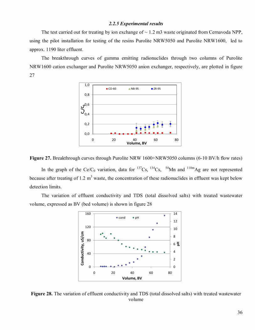
2.2.5 Experimental results
The test carried out for treating by ion exchange of ~ 1.2 m3 waste originated from Cernavoda NPP,
using the pilot installation for testing of the resins Purolite NRW5050 and Purolite NRW1600, led to
approx. 1190 liter effluent.
The breakthrough curves of gamma emitting radionuclides through two columns of Purolite
NRW1600 cation exchanger and Purolite NRW5050 anion exchanger, respectively, are plotted in figure
27
0,0
0,2
0,4
0,6
0,8
1,0
0 20 40 60 80
C e/C
0
Volume, BV
CO-60 NB-95 ZR-95
Figure 27. Breakthrough curves through Purolite NRW 1600+NRW5050 columns (6-10 BV/h flow rates)
In the graph of the Ce/C0 variation, data for 137Cs, 134Cs, 54Mn and 110mAg are not represented
because after treating of 1.2 m3 waste, the concentration of these radionuclides in effluent was kept below
detection limits.
The variation of effluent conductivity and TDS (total dissolved salts) with treated wastewater
volume, expressed as BV (bed volume) is shown in figure 28
0
2
4
6
8
10
12
14
0
40
80
120
160
0 20 40 60 80
pH
Cond
ucti
vity
, uS/
cm
Volume, BV
cond pH
Figure 28. The variation of effluent conductivity and TDS (total dissolved salts) with treated wastewatervolume
37
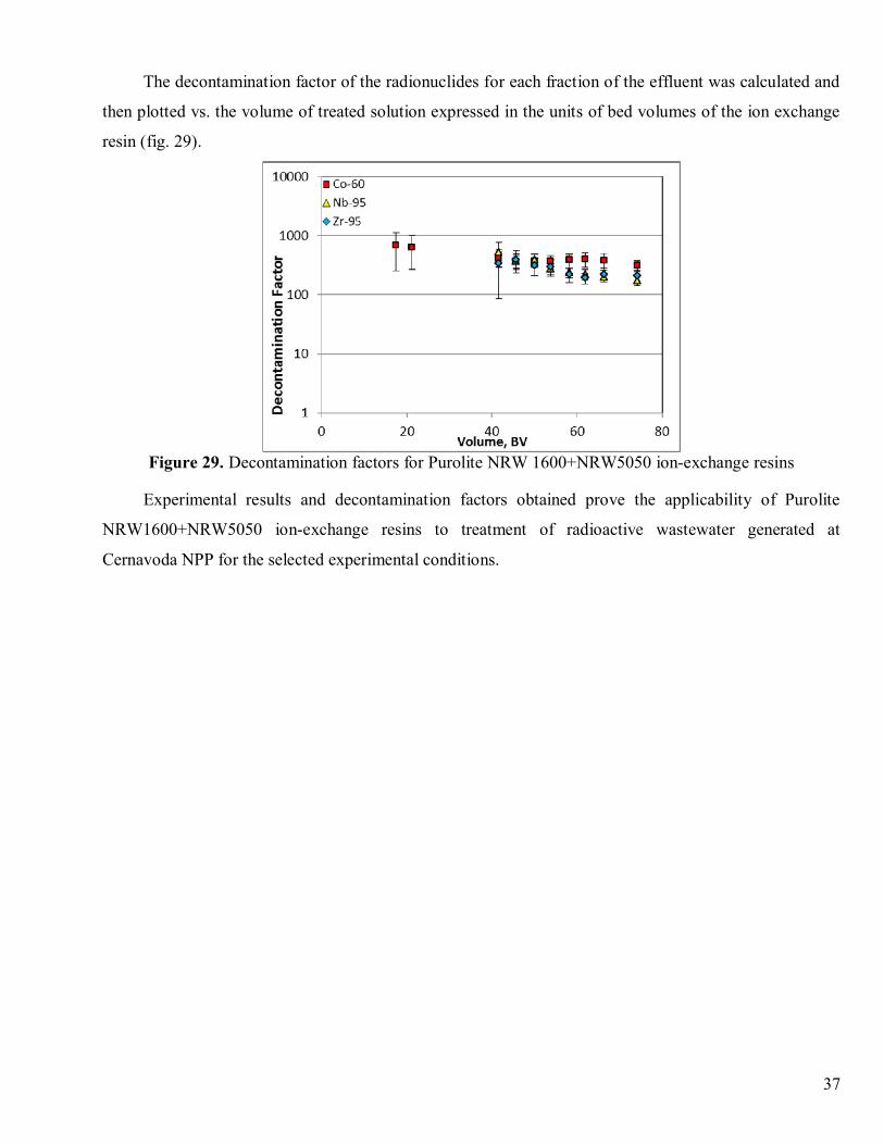
The decontamination factor of the radionuclides for each fraction of the effluent was calculated and
then plotted vs. the volume of treated solution expressed in the units of bed volumes of the ion exchange
resin (fig. 29).
Figure 29. Decontamination factors for Purolite NRW 1600+NRW5050 ion-exchange resins
Experimental results and decontamination factors obtained prove the applicability of Purolite
NRW1600+NRW5050 ion-exchange resins to treatment of radioactive wastewater generated at
Cernavoda NPP for the selected experimental conditions.
38
3. TECHNOLOGY FOR TREATMENT OF AQUEOUS RADIOACTIVE WASTE FROM
CERNAVODA NPP
The objectives proposed for the aqueous radioactive waste treatment technology elaborated were:
- maintaining the radioactive content of aqueous waste from Cernavoda NPP below the LEM
control limit or below DEL.
- an increased volume reduction factor
- a simple, secure and easy to operate installation
- an acceptable treatment cost.
The ion exchange process was selected for the treatment of aqueous radioactive waste from
Cernavoda NPP, taking in consideration the following:
P The treated liquid radioactive wastes are diluted aqueous solutions (£ 0.1%), reason for which
the ion exchange resins are spent slowly, and the spent ion exchange media volume is much less than the
treated waste volume.
P The effluents radioactivity is low enough to be discharged.
P The spent resins radioactivity doesn’t influence their stability.
P The treatment process was tested at pilot-scale, using aqueous radioactive waste from Cernavoda
NPP.
P The components of installation for treatment by ion exchange are simple and easy to operate.
3.1 Flow chart of technology for treatment of liquid radioactive waste from Cernavoda NPP
The mostly synthetic organic ion exchange resins are based on a copolymer of styrene and
divinylbenzene which are fixed functional groups, like –SO3H, -(SO3Na) for strong acidic cation
exchangers, - COOH for weak acidic cation exchangers and –NH3+ or –N2
+ functional groups for anion
exchangers.
The selectivity of ion exchange processes depends on the following factors:
P The ion exchanger type
P The ions valences, the ionic species present in waste and their concentrations
P The type of counter ions and their concentration
P Ion exchange parameters (temperature, pressure, flow rate, ion exchange capacity).
Ion exchange processes can be operated in batch or continuous modes. We chose the continuous
operation, when the media is contained in a vessel and the liquid is pumped through the media under
pressure. Separate vessels can be used for cation and anion exchange, or the media can be combined into
39
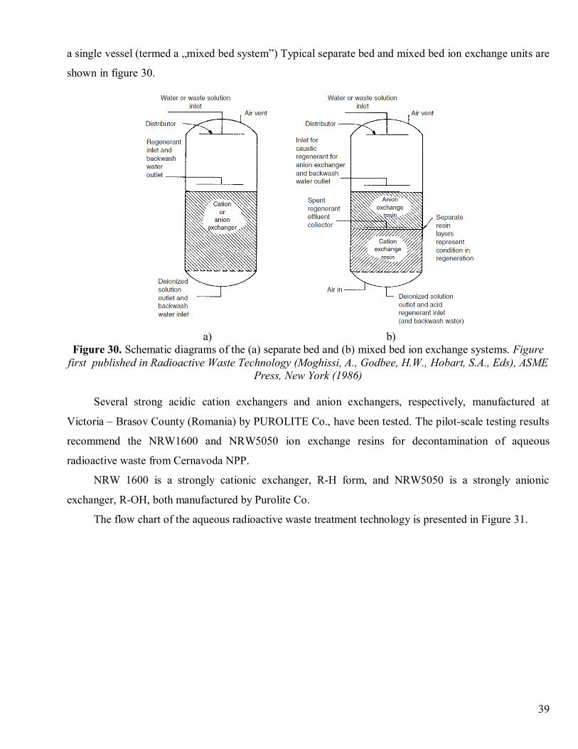
a single vessel (termed a „mixed bed system”) Typical separate bed and mixed bed ion exchange units are
shown in figure 30.
a) b)Figure 30. Schematic diagrams of the (a) separate bed and (b) mixed bed ion exchange systems. Figure
first published in Radioactive Waste Technology (Moghissi, A., Godbee, H.W., Hobart, S.A., Eds), ASMEPress, New York (1986)
Several strong acidic cation exchangers and anion exchangers, respectively, manufactured at
Victoria – Brasov County (Romania) by PUROLITE Co., have been tested. The pilot-scale testing results
recommend the NRW1600 and NRW5050 ion exchange resins for decontamination of aqueous
radioactive waste from Cernavoda NPP.
NRW 1600 is a strongly cationic exchanger, R-H form, and NRW5050 is a strongly anionic
exchanger, R-OH, both manufactured by Purolite Co.
The flow chart of the aqueous radioactive waste treatment technology is presented in Figure 31.
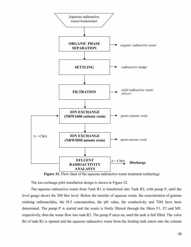
40
Figure 31. Flow chart of the aqueous radioactive waste treatment technology
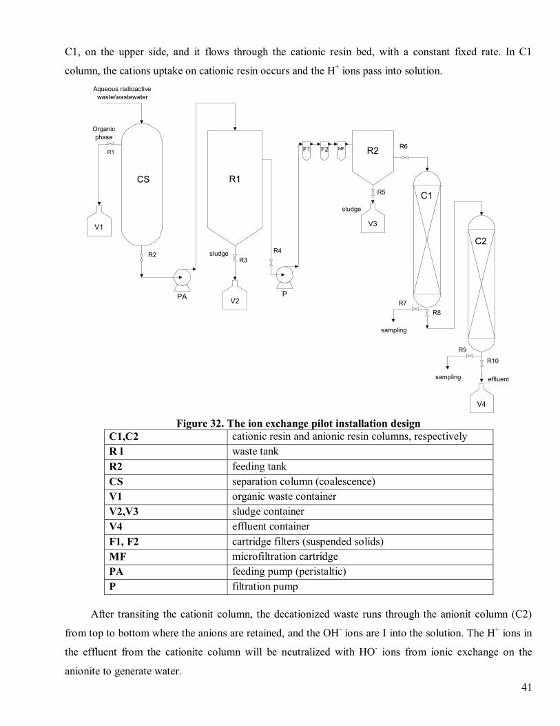
The ion exchange pilot installation design is shown in Figure 32.
The aqueous radioactive waste from Tank R1 is transferred into Tank R2, with pump P, until the
level gauge shows the 200 liter level. Before the transfer of aqueous waste, the concentration of gamma
emitting radionuclides, the H-3 concentration, the pH value, the conductivity and TDS have been
determined. The pump P is started and the waste is firstly filtered through the filters F1, F2 and MF,
respectively, then the waste flow into tank R2. The pump P stays on, until the tank is full filled. The valve
R6 of tank R2 is opened and the aqueous radioactive waste from the feeding tank enters into the column
Λ < CMA Discharge
Λ > CMA
organic radioactive waste
radioactive sludge
solid radioactive waste(filters)
spent cationic resin
spent anionic resin
EFLUENTRADIOACTIVITY
ANALASYS
ION EXCHANGE(NRW5050 anionic resin)
ION EXCHANGE(NRW1600 cationic resin)
FILTRATION
ORGANIC PHASESEPARATION
SETTLING
Aqueous radioactivewaste/wastewater
41
C1, on the upper side, and it flows through the cationic resin bed, with a constant fixed rate. In C1
column, the cations uptake on cationic resin occurs and the H+ ions pass into solution.
Figure 32. The ion exchange pilot installation designC1,C2 cationic resin and anionic resin columns, respectivelyR l waste tankR2 feeding tankCS separation column (coalescence)V1 organic waste containerV2,V3 sludge containerV4 effluent containerF1, F2 cartridge filters (suspended solids)MF microfiltration cartridgePA feeding pump (peristaltic)P filtration pump
After transiting the cationit column, the decationized waste runs through the anionit column (C2)
from top to bottom where the anions are retained, and the OH- ions are I into the solution. The H+ ions in
the effluent from the cationite column will be neutralized with HO- ions from ionic exchange on the
anionite to generate water.
R2
R1
V2
F1
PA P
F2 MF
V3
V4
V1
Aqueous radioactivewaste/wastewater
Organicphase
CS
C1
C2
sampling
sampling
sludge
sludge
effluent
R6R1
R2R3
R4
R5
R7R8
R9
R10
42
The conductivity of the final effluent is reduced due to ionic species retained on the resin and the
generation of the hard dissociable water. Because of this effluent conductivity measurement during the
process technology is needed to assess the degree of waste decontamination. Increasing the conductivity
of the effluent is produced by major ions leak from the waste, often caused by depletion of the resin, but
also by some operating incidents that can lead to leaks, to the creation of preferential channels in the resin
mass or involving the resin in the effluent.
Two cations columns and two anions columns successively linked are proposed to be used at the
industrial scale to extinguish these deficiencies.
After passing through the ions exchanger columns, the effluent is collected into a collecting
container (V4) and stored until it is determined the radioactivity concentration. If the radioactivity
concentration of the effluent is less than the maximum agreed level, the effluent is discharged, otherwise
the effluent is recirculated. The columns are gravity fed and establishing the flows and interrupting-
starting the process is done through valves mounted on the link pipes of the installation components. The
installation components are mounted on a rack and positioned in such a way that it ensures gravity
feeding of the columns.
3.2 Pilot installation design
The pilot installation has been manufactured at ICN Pitesti for testing the ion exchanger
materials performances used for aqueous radioactive waste decontamination. The pilot installation
consists of two series columns, each with 160 mm in diameter and 800 mm high. The resin beds were 500
mm and 300 mm deep, respectively. The apparent contact time was 10 min for cationit and 6 min for
anionit, i.e. a maximal flow rate of 20 bed volumes/h.
Lab-scale tests showed that the pilot installation could treat 700 bed volumes before a break-
through to occur. The highest decontamination factor achieved by the nuclear grade Purolite resins was
104.
The pilot installation used for ion exchange treatment of the aqueous radioactive waste from
Cernavoda NPP has the following main components:
- column for organic phase separation (figure 33a)
- two cartridge filters and one microfiltration cartridge for particulate material separation
- radioactive waste storage tank of 1 m3 capacity (figure 33b)
- cationite column feeding tank, with level gauge glass (figure 33c)
- two ions exchanger columns, each of them with level gauge glass (figure 33d)
- corrosion-proof pump for waste filtration/feeding of the pilot installation
- secondary waste collecting containers, effluents respectively.
43
a) b) c) d)Figure 33. Components of the ion exchange pilot installation
The pilot installation was used to set the optimal treatment parameters.
The technical specifications for the pilot installation are:
Radioactive waste storage tank is made from fiber glass reinforced polyester and has a volume of 1
m3. On the upper side, the tank has a central fitting (Dn=400mm) used for waste transfer pump and on the
bottom side there is a Dn=50mm fitting with a valve for sediment exhausting. On the lateral side, there is
a Dn=50mm fitting with a valve for waste filling to the feeding tank.
The radioactive waste storage tank is corrosive-proof, both to acid and alkaline agents.
The feeding tank has a 200L volume, it is a stainless steel cylinder having D=600mm, h=650mm
and a funnel-shaped bottom of h=160mm. A connecting pipe with valve for feeding the cationite column
is on the inferior side panel and a fitting for exhausting of the possible colloidal sludge sediments is
attached to the bottom of the feeding tank. The upper side of the tank is a detachable lid for cationite
feeding coupled with the exhausting hose from the microfilter.
The feeding tank has a level gauge glass on a height of 570mm. The tank is mounted on a frame to
ensure the height difference required for feeding.
Filtration/transfer pump of the waste from the storage tank to the feeding tank is a corrosion-proof
pump that ensures a pressure of 4 bars, maximum allowed for microfiltration.
Ions exchanger resin columns are made of stainless steel (D=160mm and h=800mm) with flanges
on the inferior side. The column lid has a connecting pipe to the waste feeding tank. The columns have a
tronconical shaped bottom, flange mounted and are equipped with glass level. The bottom flange of the
column secures a perforated plate, which supports the stainless steel sieve with mesh size up to 0.3 mm.
44
The sieve retains the resin pearls. On the bottom-side panel, the column has a closed connecting pipe with
a blind flange for exhausting of the spent resin. Also, on the bottom side, the column is provided with an
effluent exhausting fitting and a valve for sampling. The effluent exhausting fitting has a valve and it is
connected through the stainless steel pipe to the feeding fitting of the anionite column.
The two columns (cationite and anionite) are identical; the cationite column is positioned under the
feeding tank and the anionite column is placed in such a manner that there is a level difference fall
between the two columns. This position ensures the feeding of the columns through free fall. All the pipes
are detachable, stainless steel made.
Effluent container is a 130L tank, located near to the anionite column.
Cartridge filters
Two cartridge filters, Dual-Gradient Density (DGD) type, assembled into Big Blue® filter housings,
model #10 Big Blue® - ¾” (manufactured by Pentair Filtration Inc. – Pentek) were installed for the solid
suspension separation.
The installed filters use cartridges manufactured by Pentair Water Treatment – Pentek Filtration,
with the following performance data:
- filter media: polypropylene
- temperature range: 4.4 ÷ 62.8 °C
· filter model DGD-7525
-pre-filter micron rating (nominal): 75 µm
-post-filter micron rating (nominal): 25 µm
-flow rate = 38 l/min (initial ΔP<0.1 bar)
· filter model DGD-2501
-pre-filter micron rating (nominal): 25 µm
-post-filter micron rating (nominal): 1 µm
-flow rate = 38 l/min (initial ΔP<0.1 bar).
The physico-chemical properties of the liquid waste from Cernavoda NPP impose an additional
filtration step for the prevention of resin bed fouling. With this purpose, a microfiltration pleated cartridge
filter was installed within the pilot installation.
The microfiltration cartridge is used for the removal of particulate material from wastewater. The
separation is achieved by dead end filtration, when the particles accumulate on the filter surface.
The installed microfiltration cartridge uses Memtrex-NY filter, manufactured by GE –
Water&Process Technologies, with the following characteristics:
- filtration media: Hydrophilic Nylon66 Membrane
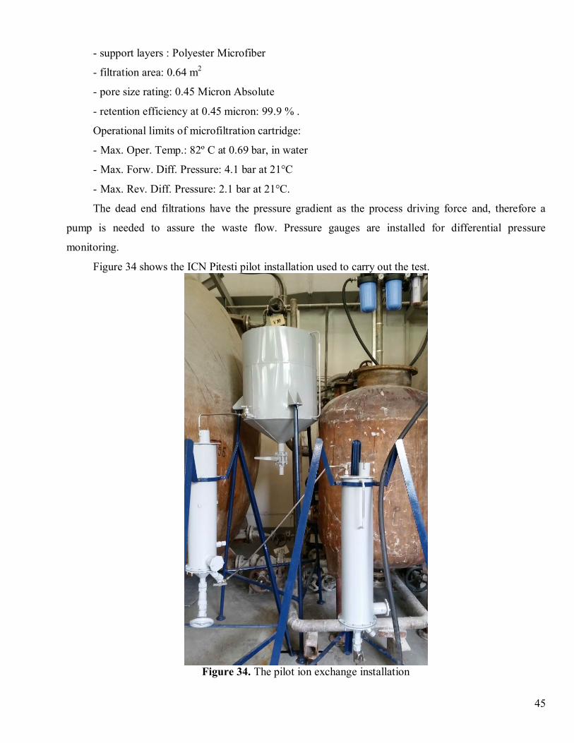
45
- support layers : Polyester Microfiber
- filtration area: 0.64 m2
- pore size rating: 0.45 Micron Absolute
- retention efficiency at 0.45 micron: 99.9 % .
Operational limits of microfiltration cartridge:
- Max. Oper. Temp.: 82º C at 0.69 bar, in water
- Max. Forw. Diff. Pressure: 4.1 bar at 21°C
- Max. Rev. Diff. Pressure: 2.1 bar at 21°C.
The dead end filtrations have the pressure gradient as the process driving force and, therefore a
pump is needed to assure the waste flow. Pressure gauges are installed for differential pressure
monitoring.
Figure 34 shows the ICN Pitesti pilot installation used to carry out the test.
Figure 34. The pilot ion exchange installation
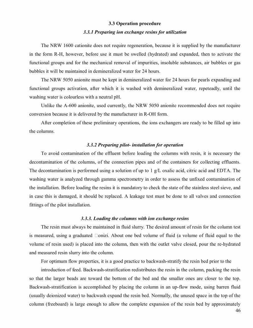
46
3.3 Operation procedure
3.3.1 Preparing ion exchange resins for utilization
The NRW 1600 cationite does not require regeneration, because it is supplied by the manufacturer
in the form R-H, however, before use it must be swelled (hydrated) and expanded, then to activate the
functional groups and for the mechanical removal of impurities, insoluble substances, air bubbles or gas
bubbles it will be maintained in demineralized water for 24 hours.
The NRW 5050 anionite must be kept in demineralized water for 24 hours for pearls expanding and
functional groups activation, after which it is washed with demineralized water, repeteadly, until the
washing water is colourless with a neutral pH.
Unlike the A-600 anionite, used currently, the NRW 5050 anionite recommended does not require
conversion because it is delivered by the manufacturer in R-OH form.
After completion of these preliminary operations, the ions exchangers are ready to be filled up into
the columns.
3.3.2 Preparing pilot- installation for operation
To avoid contamination of the effluent before loading the columns with resin, it is necessary the
decontamination of the columns, of the connection pipes and of the containers for collecting effluents.
The decontamination is performed using a solution of up to 1 g/L oxalic acid, citric acid and EDTA. The
washing water is analyzed through gamma spectrometry in order to assess the unfixed contamination of
the installation. Before loading the resins it is mandatory to check the state of the stainless steel sieve, and
in case this is damaged, it should be replaced. A leakage test must be done to all valves and connection
fittings of the pilot installation.
3.3.3. Loading the columns with ion exchange resins
The resin must always be maintained in fluid slurry. The desired amount of resin for the column test
is measured, using a graduated onizi. About one bed volume of fluid (a volume of fluid equal to the
volume of resin used) is placed into the column, then with the outlet valve closed, pour the re-hydrated
and measured resin slurry into the column.
For optimum flow properties, it is a good practice to backwash-stratify the resin bed prior to the
introduction of feed. Backwash-stratification redistributes the resin in the column, packing the resin
so that the larger beads are toward the bottom of the bed and the smaller ones are closer to the top.
Backwash-stratification is accomplished by placing the column in an up-flow mode, using barren fluid
(usually deionized water) to backwash expand the resin bed. Normally, the unused space in the top of the
column (freeboard) is large enough to allow the complete expansion of the resin bed by approximately
47
80-100%. After allowing the bed to expand for 15 – 20 minutes, gradually reduce the flow to zero,
allowing the bed to gravity settle. Do not force the bed to pack by draining the column through the outlet.
This can result in extremely poor flow characteristics, possibly rendering your data useless. Also, make
sure that the column is not allowed to „run dry”. This will cause cracking and channeling within the resin
bed. If air does happen to enter the bed, re-fluidize and re-pack the bed before continuing. Once the bed is
packed it is usually a good idea to pass several bed volumes (BVs) of de-ionized water through the bed to
rinse out any trace of accumulated degradation products, common in resins that are stored for long
periods of time prior to use [http://www.dow.com/liquidseps].
3.3.4. Settleable solids separation and organic phase separation
The liquid radioactive waste transport container is placed near the pilot installation. A corrosion-
proof pump is used to feed the waste to the treatment installation. The pump sorb is sunk in the
radioactive waste container and the pump discharge path is coupled either to the reservoir of the
installation, if the organic phase is missing, or to the organic phase separation column.
The aqueous phase is transferred in the radioactive waste storage tank of the pilot installation and
the organic phase is stored for treatment.
After the solid particles sedimentation, the slurry decantated in the storage tank is discharged by
opening the valve mounted at the bottom of the tank and is transferred to the cementation unit for
conditioning according to approved technology. This operation is carried out after treating several waste
batches and only if sediments are detected.
3.3.5. Aqueous radioactive waste clean-up
The connections between the individual components are done by verifying the tightness of the
connections. By starting pump P, the waste is transferred from storage tank in the feeding tank, through
feeding tanks-columns are opened and the flow is adjusted to the 1L/min.
The optimal flow rate was determined considering the resin bed height, the column section, and the
results obtained at laboratory level and the recommendations from the specific literature.
First, the waste will pass through the filter cartridges, where particles with dimensions >0.45µm are
retained, then through the column with cationit, where the decationisation occurs and then through anionit
where the anionit species are uptaken.
The normal operating conditions are:
· the liquid that will be treated must be clear, the admissible suspended particulate content being
10mg/l;
48
· the influent must be distributed uniformly on the bed of resin, this being achieved by maintaining
the level of the aqueous waste above the upper limit of the resin bed.
3.3.6. Effluent storage and discharge
The effluent resulted from the process is collected in the storage tanks. In order to discharge the
effluent, a representative sample is taken for determining the concentrations of the gamma emitting
radionuclides, H-3 and pH.
In case the activity does not exceed admissible activity and pH is the range of 6-8.5, the effluent is
discharged. In case the activity exceeds the maximum admissible levels, the effluent will be reintroduced
in the treatment process. If the activities allow the discharge, but the pH is out of recommended range, the
pH will be adjusted with a solution of HCl 6N or NaOH 6M, depending of the type of the effluent: basic
or acid.
The neutralization is made by adding, while stirring, NaOH or HCl solution. The solution volume
shall be established by laboratory tests.
3.3.7. Discharging spent ion exchange media
The resin exhaustion is highlighted by the determination of conductivity, pH and radioactivity. The
pH change, the increased activity and increased conductivity of effluent indicates that the resin is
exhausted. In this case, the feeding valve of the waste columns is closed and the liquid from the column is
let to drain. The connection valves are closed and the flanges on the side of the column are switched off.
The discharge is done using a water jet and the suspension is collected in a 60 l drum. After discharge, it
will be measured the dose rate at the wall of the drum, the unfixed contamination and the activity of the
resin. The spent resin will be stored as solid waste and conditioned using the spent ion exchange
conditioning plant, from ICN Pitesti, by applying a licensed technology.
3.4. Processing parameters for treatment by ion exchange of aqueous radioactive waste from
Cernavoda NPP
The analysis of the effluents resulted from experiments carried out on the pilot installation led to
values of the activity that allow their discharged in accordance with environmental legislation However,
the inadequate choice a some parameters of the process may lead either to obtaining some effluents with
activity greater than accepted values, either to decreasing the efficiency of treatment process, by getting a
volume reduction factor lower than expected.
The main parameters that influence the treatment process are:
49
-the composition and physico-chemicals characteristic of waste;
-the type of ion exchange resins and the form in which are used;
-the flow rate and velocity through the columns;
-the depth of the resin bed crossed by waste.
From the results obtained for pilot scale tests, the optimal values of process parameters have been
established for the ion exchange treatment technology of aqueous radioactive waste from Cernavoda
NPP.
3.4.1. Chemical and radiochemical characteristics of aqueous radioactive waste
The process efficiency and effluent quality are influenced by characteristics of aqueous radioactive
waste. The concentration of total solids in the wastewater should be as low as possible and, after filtration
less than 10 mg/l. The concentration of total dissolved salts (TDS) in wastewater should be very low to
achieve a maximum efficiency of ion exchange process. It was established the ion exchange process at an
agreed content of maximum 2.5 mg/l total dissolved salts, but TDS should be less than 1.5 g/l in order to
reach the optimum efficiency.
The pH value of wastewater influences the ion exchange by elution/leaching ions or by increasing
concentration of the ionic dissolved species. The pH range recommended for influent is 1 – 8.
The waste radioactivity can affect the process efficiency as ion exchangers have limited stability to
radiation, a high dose of radiation causing the degradation of the resin which has the effect of lowering
the exchange capacity.
In the specialty literature it was reported that at a dose of 109 R the exchange capacity of strong acid
cation decreases with 10% and of strong basic anions with 40%. In the experiments carried out at pilot
scale, it was found that the waste radioactivity did not produce significant changes in process efficiency
and did not create operational problems.
Since aqueous radioactive waste from Cernavoda have low activity, the resin transfer activity does
not lead to major changes in the structure and its exchange capacity.
The required characteristics of the aqueous waste that can be effectively treated by ion exchange
are:
- total dissolved salts(TDS): max. 2.5g/l;
- pH:1-8;
- suspended particulate (after filtration): 10mg/l;
- radioactivity conc.: 0.1Ci/m3.
50
3.4.2. Selected ion exchange resins – characteristics
For choosing the most efficient ion exchangers, there were tested both strongly acid cations but also
strong and weak basic anions. The experiments were carried out at laboratory level and the ion exchanger
resins were selected based on the results and then tested at pilot scale.
There were tested cations NRW160, NRW1600, C-100H type, the anions NRW5050, NRW5070,
A600, A-500, A-100 type and bed mixt NRW-3550.
Based on the results obtained at laboratory scale, there were selected the ion exchangers NRW 1600
and NRW5050 type to be tested at pilot scale.
The results obtained at pilot scale recommend using the couple of ion exchangers tested for
implementation within the treatment technology by ion exchange of liquid radioactive waste from
Cernavoda NPP. The major characteristics of these exchangers are shown in the Analysis Certificates
provided by the producer.
There were selected the strongly acid cationit and strongly basic anion because the exchange
capacity is kept to the maxim value regardless of the ion strength of the wated and in a wide range of the
pH.
3.4.3. Establishing parameters which control the ion exchange resins performances
The performances of ion exchangers are governed of the physico-chemical properties of the resin
and the operating conditions. The physico-chemical properties include the exchange capacity, the degree
of crosslinking and the size of beads, the selectivity, the process kinetics and the chemical and thermal
stability.
The operating conditions include the chemical form of the chemical species, the temperature, pH,
the influent flow rate, the dept of resin beds.
1. The size of resin beads affects the kinetics of the ion exchange in that the beads with small
diameters and big specific surface determine a higher velocity of exchange, so that a higher flow of
supply is allowed. The disadvantages using the resins with small granules (gel type) consist of the
significantly reducing of the flow rate, clogging the resin bed, difficulties in operating the installation and
the risk of contaminating the effluents by entrained the resins particles. Therefore in the nuclear field it is
preferred the ion exchangers of macroporous type, with beads of a diameter >0.4mm. The selected resins
for the technology elaborated are between 0.4 and 1.1 mm diameter.
2. The resin bed length imposes the velocity and the flow rate of the waste through the column, but
the bed geometry may favor the formation of preferential flow path in the resin bed, leading to changes in
the waste flow profile. In the design and operation stage of the resin beds, there must be a balance
between the the flow rate and the bed depth. The kinetics of the ion exchange process is controlled by
51
diffusion of ions in solution to the active groups and in the resin beads. A high value of the flow rate
reduces the residence time necessary for ions diffusion, which require deeper beds that induce the
formation of channels and changes in the flow profile. Following the laboratory-scale experiments, for the
pilot scale test it was chosen a 30 to 50 cm length of the resin bed.
3. The resin-waste contact time necessary to achieve the ionic exchange is a very important
parameter since, depending on the reaction rate, part of the process parameters are established. The time
required to obtain a maximum distribution coefficient, considered the optimum time for the waste passing
through the ion exchange columns, was determined at the laboratory scale on different types of
radioactive waste. The necessary time to reach sorption equilibrium ranges between 5-10 minutes. The
necessary liquid residence time on the resin layer, must be correlated with the flow rate and with the
appropriate depth of the resin bed to avoid the preferential path flow formation and liquid flow
perturbation. Following the pilot scale experiments, it was chosen a 30-50 cm depth for the resin bed and
a flow rate of ~1 L/h, corresponding to a flow velocity of 5 cm/min.
4. The waste processing temperature through ionic exchange is the room temperature; high
temperatures, although have the role to increase the process efficinency, cause the resin decay.
5. The resin volume used at pilot scale was of 10 L cationite and 6 L anionite. Depending on the
waste composition and on the available exchange capacity, the anionite/cationite (v/v) ratio varies up to
3/1.
3.4.4. Influent flow rate and flow velocity through ion exchange resin bed
The waste flow rate and flow velocity through the ion exchangers columns were calculated taking
into account the columns section, the minimum time necessary to achieve the ionic exchange and the
depth of the resin bed. From the experiments, for the pilot scale installation the optimum flow rate was
established at ~1 L/h, corresponding to a flow velocity of 5 cm/min.
52
4. RECOMMENDATIONS ON THE TYPE, DIMENSIONING OF SPECIFIC EQUIPMENT ANDCONSTRUCTION MATERIALS
Theoretical basis of the equipment necessary for application of the technologyExperimental work presented in previous reports doubled by the mathematical modeling work offer
important information concerning the equipment type recommended to be used in the industrial process,
the materials used and the scale-up procedure.
First of all, an overview about the wastewater treatment technology improvement implies a first
step with estimation of the strategy to be followed in the equipment designing. Two important ways could
be imagined: one linked to small storage capacities and low processing installations capacities (that way
imply low investment costs but probably high operating costs versus other way) and the second one
implying high storage capacities of the contaminated wastewater doubled by high processing installation
capacities. Obvious, since we talk about wastewater contaminated with some radionuclide it is preferable
to diminish to maximum possible the residence time of the radionuclide in the industrial plant (with
respect to the safety or specific laws for nuclear activity plants – linked with wastewater treatment). That
means a fast water treatment; the recovery of important species and the water recycle in the system. But
our recommendation is to take a decision about the wastewater treatment capacity in accordance with
available data concerning the wastewaters quantities in time available from the industrial plant. So not
only technical and safety reasons should be considered but also economical criterion should be taken into
account.
Applying the results given by the experimental and theoretical research means to follow two steps:
the scale-up laboratory devices and the detailed designing of all industrial devices needed in the
wastewater treatment plant.
A start-up point of scale-up activity it should be the conception of the technological scheme (at
industrial scale). Some devices (like storage vessels, pumps, pipes) are not present during the laboratory
experiments. So a first draft of a possible technological scheme (with possible options) will give a first
image of this issue. A secondary path of the installation, designated to the resin change in the system
obviously should be considerate and also the periodically clean-up of all devices and pipes.
The considered storage vessel capacity should be in accordance with the wastewater input
accounted and the installation treatment capacity. Also, another important point liked to this device
should be the mixing device of the storage tank. Since the experimental work at laboratory scale is done
at constant concentration of the radionuclide in the input wastewater, the same procedure should by apply
at industrial scale. Any sedimentation process that could occur during the storage time (between two
processing periods) must be eliminated. A simple mechanical stirring device or a recycle path of the
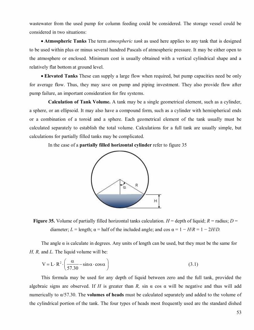
53
wastewater from the used pump for column feeding could be considered. The storage vessel could be
considered in two situations:
· Atmospheric Tanks The term atmospheric tank as used here applies to any tank that is designed
to be used within plus or minus several hundred Pascals of atmospheric pressure. It may be either open to
the atmosphere or enclosed. Minimum cost is usually obtained with a vertical cylindrical shape and a
relatively flat bottom at ground level.
· Elevated Tanks These can supply a large flow when required, but pump capacities need be only
for average flow. Thus, they may save on pump and piping investment. They also provide flow after
pump failure, an important consideration for fire systems.
Calculation of Tank Volume. A tank may be a single geometrical element, such as a cylinder,
a sphere, or an ellipsoid. It may also have a compound form, such as a cylinder with hemispherical ends
or a combination of a toroid and a sphere. Each geometrical element of the tank usually must be
calculated separately to establish the total volume. Calculations for a full tank are usually simple, but
calculations for partially filled tanks may be complicated.
In the case of a partially filled horizontal cylinder refer to figure 35
Figure 35. Volume of partially filled horizontal tanks calculation. H = depth of liquid; R = radius; D =
diameter; L = length; α = half of the included angle; and cos α = 1 − H/R = 1 − 2H/D.
The angle α is calculate in degrees. Any units of length can be used, but they must be the same for
H, R, and L. The liquid volume will be:
2V L R sin cos57.30
aæ ö= × × - a × aç ÷è ø
(3.1)
This formula may be used for any depth of liquid between zero and the full tank, provided the
algebraic signs are observed. If H is greater than R, sin α cos α will be negative and thus will add
numerically to α/57.30. The volumes of heads must be calculated separately and added to the volume of
the cylindrical portion of the tank. The four types of heads most frequently used are the standard dished
54
head, torispherical head, ellipsoidal head, and hemispherical head. A partially filled horizontal tank
requires the determination of the partial volume of the heads. A formula for partially filled heads is [3]:
( )2V 0.215 H 3 R H= × × × - (3.2)
where V = volume, R = radius, and H = depth of liquid. Some simplifying assumptions which affect
the volume given by the equation are made in literature, but the equation is satisfactory for determining
the volume as a fraction of the entire head.
Container Materials and Safety. As it is known, storage tanks are made of almost any structural
material. Steel and reinforced concrete are most widely used. Plastics and glass-reinforced plastics are
used for tanks up to about 230 m3. Resistance to corrosion, light weight, and lower cost are their
advantages. Plastic and glass coatings are also applied to steel tanks. Nonferrous metals are used only
when their special properties are required. When expensive metals such as tantalum are required, they
may be applied as tank linings or as clad metals. Small tanks containing nontoxic substances are not
particularly hazardous and can tolerate a reduced factor of safety. Tanks containing highly toxic
substances and very large tanks containing any substance can be hazardous. The designer must consider
the magnitude of the hazard. The possibility of brittle behavior of ferrous metal should be taken into
account in specifying materials. The container material chooses should respect all rules imposed by the
nuclear industry. Also if clean-up process during periodically revisions implies the use of strong acids or
basic solutions that should influence the container material choose.
Pump selection. Selecting pumps for any service imply the necessity a lot of data about the liquid
to be handled, the total dynamic head, the suction and discharge heads, and, in most cases, the
temperature, viscosity, vapor pressure, and specific gravity. The task of pump selection is frequently
further complicated by the presence of solids in the liquid and liquid corrosion characteristics requiring
special materials of construction. Solids may accelerate erosion and corrosion, have a tendency to
agglomerate, or require delicate handling to prevent undesirable degradation. Since radioactive liquids are
involved in transport procedure a solution in pump selection could be choose a kinetic special pump [3]
gas lift type to reduce the nuclear contamination of the device.
Range of operation. Because of the wide variety of pump types and the number of factors which
determine the selection of any one type for a specific installation, the designer must first eliminate all but
those types of reasonable possibility.
Pump Materials of Construction In the chemical industry, the selection of pump materials of
construction is dictated by considerations of corrosion, erosion, personnel safety, and liquid
contamination. The experience of pump manufacturers is often valuable in selecting materials.
55
Presence of solids. If a liquid containing suspended solids, must be transported there are unique
requirements which must be considered. Adequate clear-liquid hydraulic performance and the use of
carefully selected materials of construction may not be all that is required for satisfactory pump selection.
Dimensions of all internal passages are critical. Must be avoided pockets and dead spots, areas where
solids can accumulate. Close internal clearances are undesirable because of abrasion. Flushing
connections for continuous or intermittent use should be provided. Chemical pump installations that
require annual maintenance costing 2 or 3 times the original investment are not uncommon. In most cases
this expense is the result of improper selection [7,9].
Concerning the ion exchange column, data about the ion exchange recommended resin were above
mentioned. Some theoretical considerations are useful for the scale-up activity.
Ion exchangers classification. Ion exchangers are classified according to (1) their functionality and
(2) the physical properties of the support matrix. Cation and anion exchangers are classified in terms of
their ability to exchange positively or negatively charged species. Strongly acidic and strongly basic ion
exchangers are ionized and thus are effective at nearly all pH values (pH 0–14). Weakly acidic
exchangers are typically effective in the range of pH 5–14. Weakly basic resins are effective in the range
of pH 0–9. Weakly acidic and weakly basic exchangers are often easier to regenerate, but leakage due to
incomplete exchange may occur [9].
Except in very small-scale applications, ion-exchangers are used generally in cyclic operations
involving sorption and desorption steps. A typical ion-exchange cycle for water-treatment applications
involves (a) backwash—used to remove accumulated solids obtained by an upflow of water to expand
(50–80 percent expansion is typical) and fluidize the exchanger bed; (b) regeneration—a regenerant is
passed slowly through the used to restore the original ionic form of the exchanger; (c) rinse—water is
passed through the bed to remove regenerant from the void volume and, in the case of porous exchangers,
from the resin pores; (d) loading—the fresh solution to be treated is passed through the bed until leakage
begins to occur.
A complete deionization with ion-exchange columns is the classical method of producing ultrapure
water for boiler feed, in electronics manufacture, and for other general uses in the chemical and allied
industries. For deionization will be necessary two exchangers with opposite functionality to remove both
cations and anions. These can be in separate columns, packed in adjacent layers in the same column, or,
more frequently, in a mixed bed. In the mixed bed case, the two exchangers are intimately mixed during
the loading step. For regeneration, backwashing separates the usually lighter anion exchanger from the
usually denser cation exchanger. The column typically has a screened distributor at the interface between
the two exchangers, so that they may be separately regenerated without removing them from the column.
56
Differences in selectivity for different species can be used to carry out separations during the
displacement [4] Multibed cycles are also used to facilitate integration with other chemical process
operations.
General Design of the ion exchange devices
A typical fixed-bed ion exchanger consists of a vertical cylindrical vessel of lined steel or stainless
steel. Linings are usually of natural or synthetic rubber. Spargers are provided at the top and bottom, and
frequently a separate distributor is used for the regenerant solution (if case). The resin bed, consisting of a
meter or more of ion-exchange particles, is supported by the screen of the bottom distributor.
Externally, the unit is provided with a valve manifold to permit downflow loading, upflow
backwash, regeneration, and rinsing. For deionization, a two exchanger assembly comprising a cation and
an anion exchanger, is a common configuration. Characteristic design calculations are presented and
illustrated by Applebaum [9]. Large amounts of data are available in published literature and in bulletins
of manufacturers of ion exchangers. In general, however, laboratory testing and pilot-plant work is
advisable to determine usable exchanger capacities, regenerant quantities, exchanger life, and quality of
product for any application not already thoroughly proven in other plants for similar conditions [9]. For
larger-scale applications, a number of continuous or semi continuous ion-exchange units are also
available. The Higgins contactor was originally developed to recover uranium from leach slurries at the
Oak Ridge National Laboratory [9]. More recently, it has been adapted to a wide variety of applications,
including large-volume water softening. The Asahi process [9] is used principally for high-volume water
treatment.
Another continuous ion-exchange system is described by Himsley and Farkas [9]. Such a system is
used to treat 1590 m3/h of uranium-bearing copper leach liquor using fiberglass- construction columns 3.7
m in diameter. The adsorption column is divided vertically into stages. Continuous transfer of batches of
resin occurs from stage to stage without any interruption of flow. This is accomplished by pumping
solution from one stage (A) to the stage (B) immediately above by means of external pumping in such a
manner that the net flow through stage B is downward, carrying with it all of the resin in that stage B.
When transfer of the ion exchanger is complete, the resin in stage C above is transferred downward in a
similar manner. The process continues until the last stage (F) is empty.
General considerations about column scale-up. Sometimes passing from laboratory scale to
industrial scale is a difficult step. The scale-up procedure should take into account various aspects
concerning the process and corresponding devices. The main recommendation about this are presented
further.
There are many different aspects related to scale-up, some of them technical and others not.
57
Economical aspect
Financially seen it looks more attractive to build one big apparatus rather than several parallel ones.
The investment costs (Inv) go up with the production capacity (Cap) and for this it holds roughly the 0.6-
rule for process equipment:
Inv~Cap 0.6
This can be simply seen by onizing that Inv~A (surface area of equipment)~L2
and Cap~V
(volume of equipment)~L3. From these two it follows Inv~Cap
2/3.
The exponent 2/3 is called the degression coefficient and changes from case to case. As long as the
degression coefficient is smaller than unity there is an economic incentive to increase the size of
equipment rather than to multiply the equipment. The degression coefficient depends, of course, on the
type of equipment. Also the effect of ‘standard’ sizes is important here. If, for example, a valve is made in
different standard sizes than it could be cheaper to buy two smaller ones than to have a large one
especially made.
General aspects of scale-up. The main aspects involved in scale-up activity are:
• Economical aspects (as it was already mentioned):
I ~ C0.6
I ~ A (area)
C ~ V (volume)
• Energy, raw materials, and environment
• Vulnerability of the production to:
- Maintenance
- Sabotage
• Logistics:
- Transportation of parts
- Supply of raw materials
- Discharge of products
• Social aspects:
- Employability, labor conditions
• Mechanical and other technical restrictions
• Start-up, management, maintenance of a plant
• Safety
58
Scale-up considerations. The scale-up of the installation could be made in two ways: multiplying
the number of pilot scale installation (by number) or by devices size enlargement (by size enlargement).
The advantages and disadvantages of each option are briefly presented as follows:
by number:
•fast design procedure: gain of time
•limited chance on practical constraints
•easier construction: small mechanical problems
•good possibility of sub-maximal production
•easier repair/cleaning; cheaper spare parts
•logistical problems in terms of distribution
•extra risk problems due to interference
by size enlargement:
•slower design procedure: loss of time
•equipment limitations due to practical constraints
•construction problems: mechanical constraints
•limited possibility for sub-optimal production
•difficult repair; limitation in spare parts
•logistical problems in terms of large quantities
•risk problems due to bulk quantities
Similarity. In the process industry all kinds of physical and chemical processes take place which in
principle can be described mathematically by means of momentum, heat, and mass balances. The
resulting description is usually too complex to allow general analytical solutions. Although these coupled
partial differential equations can be solved numerically after some computer time, the obtained solutions
are very specific and hardly suitable for generalization and analysis. In such cases it might be useful to
replace the straightforward process description by a comparative method in which the processes at two
different scales (sizes) of the process equipment are compared. From the conditions for process similarity,
scale-up criteria with respect to that equipment can then be derived. So scale-up is actually designing
using “foreknowledge”; this foreknowledge can be the result of laboratory experiments or experience
with a similar industrial process, possibly at a different scale.
Two kinds of similarity are distinguished:
· apparatus similarity, in which the dimensions of the apparatus are being scaled-up with a common
scale-up factor; afterwards it is analyzed what effect scale-up has on the processes in the apparatus.
59
· process similarity, in which a certain process variable (production, energy consumption) is being
scaled-up out of process considerations. Process requirements (such as product quality) result at process
similarity in demands for the dimensions of the apparatus. So now scale-up of the dimensions is
secondary.
Process equipment companies that produce relatively simple equipment often prefer apparatus
similarity for production reasons. Also, a series of similar apparatuses (such as pumps) ‘looks’ better.
However, often only the original design of such a series of apparatuses may be optimal and some (much)
of that quality has been sacrificed in case of the ‘derived’ apparatuses. This is (one of) the reason(s) why
the scale-up factor is never chosen far from unity and is seldom bridging one decade. With more complex
equipment and for whole production processes (factories) apparatus similarity is never considered and
only process similarity is used. Therefore, from now on, the word similarity will be used in the meaning
of ‘process similarity’. It should be mentioned that similarity between model and prototype means that the
deformation, flow, temperature and concentration profiles of model and prototype are congruent in
dimensionless form.
There exist more levels of process similarity. Moreover, there is also a certain hierarchy; each
underlying form of similarity assumes the presence of the one above. We distinguish them as: geometric
similarity (shape), mechanical similarity s: static (mechanical) deformation profiles or d: dynamic
(mechanical) similarity velocity profiles, t: thermal similarity temperature profiles, c: chemical similarity
concentration profiles. To derive the conditions for the different levels of process similarity it should be
used momentum, heat, and mass balances; these balances will be formulated such that the analogy
between these three types of transport is maximal.
General conclusions about similarity are:
• At each level of process similarity it is possible to indicate the conditions: equal dimensionless
numbers at M- and P-scale
• Soon the number of conditions is that large that these conditions can only be satisfied with a scale-
up factor equal to one
• Fortunately not all dimensionless numbers are important at all scales
• A method is needed to determine which dimensionless groups are really important and which are
allowed to vary (hopefully at a modest scale). Regime analysis provides such a method.
Finally: only seldom full process similarity is possible (or desirable). If full similarity is not possible
then partial process similarity must be accepted. The dimensionless groups, which have to be kept
constant at both scales, form together the scale-up criterion.
60
Regime analysis and scale-up criteria
Attempts to scale a process fully similar often fail due to the large number of dimensionless groups
that have to be kept constant. Reasons to partly give up full process similarity can be of :
(1) mathematical,
(2) technological or
(3) economical nature.
In the first case the conditions, which constrain the system by keeping the dimensionless groups
constant, are mathematically contradictory.
In the second case certain technological boundaries are exceeded (gas velocities near the speed of
sound, vibrations near the characteristic frequencies, etc.).
In the third case the design is becoming too expensive (special design, extreme costs of
transportation, high costs for foundations or safety).
In all cases it should give up full process similarity and have to be satisfied with partial similarity:
not all dimensionless groups required for full similarity will show in the scale-up criterion, but some will
and some do not. Clearly it is a problem of choice, entering the field of regime analysis.
Hydraulic considerations [10,11]
In literature there are some correlations for the evaluation of particle Peclet number Pep and liquid
holdup %h (as a percentage of the total bed volume) for materials that are frequently used in adsorption
and ion exchange systems
Rep
npPe N= ×
Where
N is 0.52 for upflow and 0.05 for downflow
n is –0.65 for upflow and 0.48 for downflow
Rep is particle Reynolds number p sp
d uRe
× ×r=
h
where h is the dynamic viscosity of the liquid phase,
r – liquid density;
dp – particle diameter;
us – superficial velocity.0.28% 21 99.72 sh u= + ×
Liquid holdup equation holds for particle size of 1.2-1.3 mm. Then, the bed Peclet number can be
evaluated using the following equation [12]
61
L pp
LPe Ped
= ×
The dynamic liquid holdup can be evaluated for other particle diameters following the equation:
( )( )
1 2
12
%
%
mp p
pp
h d ddh d
æ ö@ ç ÷ç ÷
è ø
Where the exponent m is 0.72 [13,14]
The constant part in liquid holdup correlation (equal to 21) is the static liquid holdup. This part is
between (0.11/ε) and (0.072/ε) for particle size between 0.2 and 2 mm, where ε is the bed voidage In the
typical case of ε=0.4-0.5 static holdup is between 14 and 27% [11].
Several authors [15-17] precise that certain geometrical analogies should be kept within the
following limits in order to avoid large-scale mal distribution of the flow
5LD
³
12 30p
Dd
³ -
50 150p
Ld
³ -
where L is the bed length, D the bed diameter and dp is the particle diameter.
Also, Ruthven [16] precises that a maximum linear velocity should not be exceeded in order to
avoid extended friction between the packing materials in both down and upflow operations. This velocity
is 0.8 times the minimum fluidization velocity for upflow operation and 1.8 times the same velocity for
downflow operation. Using this maximum working velocity and the contact time during pretreatment
(which is generally higher than the treatment one) the maximum bed high could be determined as follows:
FS FSF a V= ×
where FS stands for “full scale”
F is the volumetric flow rate and V is the bed volume
The number a is the number of bed volume per hour.
,maxFS FS
FS FSFS FS
F a Vu uA A
×= = £
A is the bed cross sectional area
umax is the maximum allowable linear velocity
Considering that VFS= AFS·LFS, it result that
,maxFSFS
uL
a£
62
Could be used a bed with a length which represent 85 % off this value.
Those considerations did not take into account the possible compression of the particles at the
bottom of the bed, under the bed weight and under the hydrostatic pressure of the fluid
But Inglezakis [13] showed that the beds of 1.4 – 1.7 mm particle size can be very high (50 m).
Also, in Inglezakis et al. [11] is developed the following relation to estimate the full scale flow rate:
( )2104
FSFS LS
a LF D × p ×£ × ×
where LS stands for laboratory scale
The bed porosity should be the same. It is a function of D/dp, but for dp/D values (lower than 0.1) it
is practically constant.
Maintaining fluid flow in piping systems
The primary purpose of any piping system is to maintain free and smooth flow of fluids through the
system. Another purpose is to ensure that the fluids being conveyed are kept in good condition (i.e., free
of contamination). Piping systems are purposely designed to ensure free and smooth flow of fluids
throughout the system, but additional system components are often included to ensure that fluid quality is
maintained. Piping system filters are one example, and strainers and traps are two others. It is extremely
important to maintain free and smooth flow and fluid quality in piping systems, especially those that feed
vital pieces of equipment and machinery. Consider the internal combustion engine, for example.
Impurities such as dirt and metal particles can damage internal components and cause excessive wear and
eventual breakdown.
To help prevent such wear, the oil is run continuously through a filter designed to trap and filter out
the impurities. Other piping systems need the same type of protection that the internal combustion engine
does, which is why most piping systems include filters, strainers, and traps. These filtering components
may prevent damage to valves, fittings, the pipe, and to downstream equipment/machinery. Chemicals,
various types of waste products, paint, and pressurized steam are good examples of potentially damaging
fluids. Filters and strainers play an important role in piping systems, protecting both the piping system
and the equipment that the piping system serves.
Scaling
Since sodium and calcium hypochlorite are widely used in water and wastewater treatment
operations, problems common in piping systems feeding this chemical are of special concern.
Maintaining the chlorine in solution (used primarily as a disinfectant), sodium hydroxide (caustic) is used
to raise the pH of the hypochlorite; the excess caustic raises the shelf life. A high pH caustic solution
raises the pH of the dilution water to over pH 9.0 after it is diluted. The calcium in the dilution water
reacts with dissolved CO2 and forms calcium carbonate. Experience has shown that 2-in. pipes have

63
turned into ¾-in. pipes due to scale buildup. The scale deposition is greatest in areas of turbulence such as
pumps, valves, rotameters, backpressure devices, etc. If lime (calcium oxide) is added (for alkalinity),
plant water used as dilution water will have higher calcium levels and generates more scale. While it is
true that softened water will not generate scale, it is also true that it is expensive in large quantities. Many
facilities use softened water on hypochlorite mist odor scrubbers only. Scaling also often occurs in
solution rotameters, making flow readings impossible and freezing the flow indicator in place. Various
valves can freeze up and pressure sustaining valves freeze and become plugged. Various small diffuser
holes fill with scale. To slow the rate of scaling, many facilities purchase water from local suppliers to
dilute hypochlorite for the return activated sludge (RAS) and miscellaneous uses. Some facilities have
experimented with the system by not adding lime to it. When they did this, manganese dioxide (black
deposits) developed on the rotameter’s glass, making viewing the float impossible. In many instances,
moving the point of hypochlorite addition to downstream of the rotameter seemed to solve the problem. If
remedial steps are not taken, scaling from hypochlorite solutions can cause problems. For example, scale
buildup can reduce the inside diameter of pipe so much that the actual supply of hypochlorite solution
required to properly disinfect water or wastewater was reduced. Because of the scale buildup, the
treatment system itself will not function as designed and could result in a hazardous situation in which the
reduced pipe size increases the pressure level to the point of catastrophic failure. Scaling, corrosion, or
other clogging problems in certain piping systems, are far from an ideal situation [18-20] Reducing
substances deposition in the pipe system will reduce the cost of major revisions of the installation.
64
5. RECOMMENDATIONS ICN ON THE WORK SAFETY MEASURES
ALARA (As Low As Reasonably Achievable) is a radiation safety principle for minimizing
radiation doses and releases of radioactive materials by employing all reasonable methods.
The ALARA principle includes the proper use of shielding and dosimetry combined with
contamination control techniques. All employees bear a responsibility for their own personal safety in
such work areas as:
- Awareness of potential radiation hazards, exposure levels and safety controls in their work areas.
- Awareness of operating and emergency procedures.
- Awareness of practices that do not seem to follow the ALARA philosophy.
- Compliance with reporting incidents and possibly unsafe working conditions to their supervisors.
- Compliance with wearing personnel dosimetry and ensuring it’s return at the proper exchange
frequency.
- Compliance with providing bioassay samples as needed.
The three major principles to assist with maintaining doses ALARA are:
a) Time – minimizing the time of exposure directly reduces radiation dose.
b) Distance – doubling the distance between your body and the radiation source will divide the
radiation exposure by a factor of 4.
c) Shielding – using absorber materials such as Plexiglas for beta particles and lead for X-rays and
gamma rays is an effective way to reduce radiation exposures.
The following practices are effective for reducing potential internal exposures :
a) Good hygiene techniques that prohibit the consumption of food and drinks in the contaminated
area.
b) Control contamination with absorbent paper and spill trays, properly labeled waste containers,
equipment, etc. And prompt decontamination of any detected contamination.
c) Use fume hoods for materials which could become airborne (e.g., vapors, dust, aerosols, etc.)
and present an inhalation hazard to workers.
d) Use proper protective equipment (PPE) such as disposable gloves, safety glasses, lab coats, etc.
To reduce the possibility of ingestion or absorption of radioactive materials.
The following practices are effective for reducing potential risk at ion exchange resins handling:
· Wear protective eyeglasses or chemical safety goggles.
· Wear gloves impervious to this material to prevent skin contact. Gloves should be removed and
replaced immediately if there is any indication of degradation or chemical breakthrough.
· Good general ventilation should be sufficient. No respiratory protection should be needed.

65
· Never eat, drink, or smoke in work areas. Practice good personal hygiene after using this material,
especially before eating, drinking, smoking, using the toilet, or applying cosmetics.
· Avoid contact with strong oxidizing agents, particularly concentrated nitric acid. Before using
strong oxidizing agents, consult sources knowledgeable in handling such materials.
Do not pack column with dry ion exchange resins. Dry beads expand when wet. This expansion can
cause a glass column to shat.

66
6. RECOMMENDATIONS ON THE WORK SAFETY MEASURES AT INRNE
· Minimizing the buildup of radioactive material to reduce the activity of chemical and radioactive
waste and to reduce the activity of any planned discharges to the environment.
· Rational organization of the work processes and measures for radiation protection of the personnel
under normal operating conditions in the laboratory.
· Assessment of the nature and degree of the radiation risk
· Specialized training, instructions and control of the observation of the rules for safe work with
sources of onizing radiation
· Use of protective barriers against the spread of radioactive substances, protective screens, devices
for remote manipulation of sources of ionizing radiation, as well as limiting the time of work with sources
of ionizing radiation and optimization of the distance to the sources of ionizing radiation
· Use of means for personal radiation protection, organisation of radiation technological and
dosimetric control at the site
· For works of I or II class with unsealed sources of ionizing radiation the area per worker in a
given room shall be minimum 10 square meters.
· The technological equipment, protection devices and working facilities in the rooms at the site
shall be with smooth surface, of simple design and with coatings with low sorption, which facilitate the
removal of radioactive contamination and which can stand the effects of the working materials,
substances, solutions and chemical agents used.
· The floors and ceilings of the rooms for operations shall be coated with materials of low sorption,
which are durable to cleansing means. It is recommended to paint the rooms belonging to different classes
and areas of operations in different colours
· The edges of the floor coatings shall be glued to the walls, bent in advance at 10 cm height from
the floor. If special sewage system is available, the floors of the rooms shall slope down to the facilities
for draining of the water. The corners of the rooms shall be rounded and the doors and window frames
shall be of simplified design.
· In the case of activities with unsealed sources of ionising radiation of class I and II, the common
electrical distribution boards and the controls of the common systems for heating, ventilation, water
supply, gas supply and pressurised air shall be located outside the basic working rooms of the site.
· Operations with unsealed sources of ionising radiation of class I in chambers and boxes shall be
performed by remote controlled equipment or by gloves, airtight sealed to the front wall of the chambers
or boxes.
67
· Radioactive substances shall be moved from one room to another after performing of radiation
control
· The quantity of radioactive substances at the workplaces shall be the minimum required by the
particular activity. Radioactive substances with the minimum toxicity, solutions instead of powders, and
solutions with the least specific activity shall be selected.
· The number of operations, which may create a possibility for radioactive contamination of the
rooms and the environment (transferring of liquids from one container into another, sifting of powders,
etc.) shall be reduced to a minimum. Manual operations with radioactive solutions shall be performed
with the application of proper protective means.
· The air from the ventilated rooms boxes, chambers, sealed cabinets shall be cleaned from
radioactive contamination, before it is released in the atmosphere, and the activity of the released
radioactive substances shall be monitored.
· At worksites ventilation tubes (chimneys) for release of the air into the atmosphere shall be
constructed; their height shall ensure diminishing of the volume concentration of the released radioactive
substances at the point of reaching the ground to values, which, on a conservative estimation, shall not
exceed the established dose quotes for the population.
· A system for hot and cold water supply and sewage system shall be available at the laboratory.
· The water taps of the sinks shall be with hot-cold water mixing facility, which is pedal or elbow
controlled or by other methods, which do not require physical contact by the personnel. Hand dryers shall
be installed in the washing rooms for drying of the hands after washing.
· The surface radioactive contamination of rooms, means for individual protection and equipment at
work sites shall not exceed the established limits in accordance with the currently valid norms of radiation
protection.
· After completion of work the workplaces shall be cleansed and, in case of necessity, the external
surfaces of the used vessels, tools and equipment shall be deactivated to the respective limits. Specially
selected and trained personnel shall perform these operations.
· Persons working with unsealed sources of ionising radiation, or persons visiting sites, where work
is performed with unsealed sources of ionising radiation, shall be provided with means for individual
protection in accordance with the type and class of work with these unsealed sources of ionising radiation.
· At work sites, an emergency reserve of means for individual protection and individual dosimeters
shall be provided and maintained

68
· At sites, where sources of ionising radiation are operated, radiation monitoring shall be performed
of the basic characteristics of the working and surrounding environment for determination and assessment
of the exposure of the personnel and the population in the respective areas

69
7. SUMMARY OF THE RESULTS AND CONCLUSIONS
7.1 Technology efficiency
The physico-chemical and radiological properties of the aqueous radioactive waste transfered from
Cernavoda NPP led to the development of a selection scheme for appropriate tretament methods. For the
treatment of aqueos radioactive waste, the ion exchange method was selected using synthetic organic ion
exchangers.
The main benefits of radioactive waste treatment using organic ion exchangers are:
- High decontamination factors, on average 103
- High volume reduction factors for low salt content waste
- Acceptable cost price.
Organic ion exchange treatment methods limits are:
- Inefficiency of treatment for the waste with a high inactive salts content, as it leads to the rapid
saturation of the ion exchange resin.
- Relatively low stability to radiation and temperature action.
Proposed ion exchange material evaluation was preformed taking into account the following
criteria:
I. Efficiency (ion exchange capacity, selectivity, ion exchange kinetics, decontamination factor-FD,
chemical and radiological stability, hydromechanical strength )
II. Volume reduction for the secondary waste (volume reduction factor – FRV)
III. Implementing possibility (saturated material disposal possibility, ion exchanger availability).
The presented tests for aqueous radiaoctive waste treatment were performed with synthetic organic
ion exchangers, manufactured in Romania, by Purolite Company.
Considering that the aim of the decontamination process is compliance to the MEL (Monitor Liquid
Effluent Monitor) from Cernavoda NPP limit value of 5 kBq/l, the volume reduction factors obtained
from the experimental steps range from 150 to 820, and the maximum decontamination factor was
~3x10⁴ for NRW1600 resin, at a 10 BV/h flow rate in the column.
Based on the results obtained, it can be concluded:
1. The selectivity of the tested ion exchange resins for the radionuclides identified in the waste was:
Cs-137 > Ag-110m > Co-60.
2. The ionic exchange kinetics study for the tested cationic rasins, recommends the NRW1600
resin.
70
3. For the aqueous radioactive waste treatment, nuclear grade resins produced by Purolite can be
used, with very good results obtained: strong acid cationit NRW1600, in the R-H form and strong base
anionite NRW5050, in R-OH form.
4. In order to increase the efficiency of the ionic exchange process, it is necessary the filtration step
of the waste.
5. The process parameters established for the aqueous radioactive waste treatment are:
• Waste characteristics:
-total disolved salts (TDS): maximum 2.5g/l
-suspension material after filtration: max. 10 mg/l
-pH: 1-8
-maximum activity conc.: 0.1 Ci/l
• Resin type:
-strong acid cationit: NRW1600
-stong base anionit: NRW5050
-cationit/anionit ratio: 1/1 ÷ 1/3
• Operating parameters:
- flow rate : 10-20 BV/h
- flow velocity: 1-5 m/h (good mass transfer)
- column aspect ratio, H:W = 2:1 – 4:1
- resin-waste contacting time: 3-6 min
- Operating system: gravitational flow
- operating pressure: room presure
- operating temperature: room temperature
- Alloy type for plant components: stainless steel V4A
6. In order to establish the process performances and control, the following analysis are required to
be performed:
• conductivity (mS/cm)
• pH
• radioactivity (Bq/l)
• total dissolved salt content (mg/l)
7. The performances obtained were:
• volume reduction factor: 350 - 800
• decontamination factor: max. 104
71
8. The ionic mass specific consumption varies as a function of the dissolved substances content of
the radioactive waste. Thus, in the tests performed at laboratory scale, the specific cationit NRW1600
consumption was 0.001 liter/waste liter. At a concentration higher then 2.5 g/l dissolved substances, the
method becomes inefficient due to the high ion exchange consumption.
9. From the waste treatment process, it will result solid waste composed from spent ion exchangers,
spent filtration cartridges, settled slurry and eventually the organic phase. The secondary waste will be
conditioned for final disposal, using technologies available at ICN Pitesti for this type of waste.
10. The decontamination waste that uses concentrated solutions are imposible to treat efficiently at
an accessible cost price, through any method, due to the high content of complexing agents. Since these
methods are less and less used, and the generated waste volumes are small, it is recommended the
separate collection, oxidation of organic compounds, neutralization and possibly supernatant treatment
through ionic exchange and direct conditioning of the slurry.
The treatment plant for aqueous radioactive waste arising from CNE Cernavoda must be built from
stainless steel corrosive resistant media; it must be tight in order to eliminate the risk of some damages
that can compromise the security during the treatment process.
7.2 Cost consideration
Before selecting a particular ion exchange treatment process, a complete economic evaluation
should be conducted. The main cost components to be considered are:
- The cost of capital
- The initial cost of the ion exchange media
- The operating costs
- The costs associated with the treatment and disposal of the spent ion exchanger.
The aqueous radioactive waste treatment technology elaborated in the framework of WATER
Project recommends the installation a new ion exchange system in view of decreasing costs with meeting
the effluent quality requirements.
The total cost of operating process depends on the desired treatment rate and the decontamination
factor. But the cost alone is not always the most important factor in the selection process, and more
expensive options may be selected to meet other technical requirements, such as the availability of
materials or conformity with spent ion exchanger treatment systems existing on-site. So, we didn’t choose
high selective synthetic inorganic materials because the spent ion exchanger treatment and conditioning
systems available on-site are not proper for these materials. Ideally, the secondary radwaste should be
72
treated through existing on-site radioactive waste treatment systems. If new facilities are required, the
cost of providing such facilities must be taken into consideration.
Because the nuclear grade resins from these applications are disposed of as radwaste, high capacity
and long resin bed life are critical to minimizing radwaste disposal cost and volume. For most users,
radwaste disposal cost will often exceed resin purchase cost, so high resin capacity directly translates into
savings in these non-regenerable nuclear applications.
Furthermore, longer bed life means fewer bed change-outs, less work, less resin handling, and less
chance for radiation exposure.
RATEN ICN Pitesti applies the treatment of aqueous radioactive waste by ion exchange, for waste
generated in the decontamination processes. The technology used was licensed in 2000, being designed
for treatment of radioactive liquids from the decontamination centre of Cernavoda NPP. Nowadays, this
technology, based on the pair of ion exchangers (cationite and anionite): C100H Purolite/A600 Purolite,
is implemented in a mobile, compact treatment plant, for processing small volumes of waste with variable
composition, from Cernavoda NPP.
The treatment efficiency obtained with the pair of resins NRW1600/NRW5050 was compared with
the same parameter obtained for the pair C100H/A600. This leads to the conclusion that by using the
nuclear grade resins recommended by us, the volume reduction factor can be increased with about 40%.
The analysis of the economic efficiency shown that by changing the ion exchangers with nuclear grade
types, despite of the increased price of the last one, an overall reduction of costs might be achieved due to
the reduction of the secondary waste production which will lead to a decrease of the disposal costs.
Changing the aqueous waste treatment technology existent at RATEN ICN Pitesti, in accordance
with the new technology, elaborated under WATER Project, leads to a 200% increase in the price of the
resin. In spite of this, generally speaking, the technology developed is technically-economically more
efficient, due to the fact that the costs associated with the treatment and disposal of the spent ion
exchanger decrease with 40%, costs that at this moment are approximately eight times the resin
acquisition cost. Thus, an approximate calculation of the integrated process cost for aqueous radioactive
waste treatment, spent resins treatment by using on-site radioactive waste treatment systems and their
disposal show that this cost will be reduced by approximately 16% through the application of the
technology developed under WATER Project, maintaining the effluent quality and reducing the final
volume for the final disposal step.
ACKNOWLEDGEMENTS
The authors gratefully acknowledge the financial support provided by Europe Union, Romania-Bulgaria
Cross Border Cooperation Programme, in the form of the research project.

73
REFERENCES[1] Order 156/2005 of CNCAN President for approval of regulation on the classification of radioactive
waste.
[2] Combined radioactive liquid waste treatment processes involving inorganic sorbents and
micro/ultrafiltration, M. Dulama, N. Deneanu, M. Pavelescu, L. Pasăre, , Rom. Journ. Phys., Vol. 54,
Nos. 9–10, P. 851–859, Bucharest, 2009
[3] Radioactive waste management at Cernavoda NPP after 5 years of experience, Daniela Răducea, CNE
PROD Cernavoda Romania, International Conference Nuclear Energy for New Europe 2002, Kranjska
Gora, Slovenia, September 9-12, 2002.
[4] Improvement of radioactive waste management at WWER NPP Kozloduy from IAEA TECDOC
1492-2006
[5]C.M. Arsene, D.Negoiu, The bituminization of ion exchangers contaminated with 14C in view of final
disposal, Conference “Nuclear 2001”, SCN Pitesti, 2001
[6] A.Piscureanu, I.Chican, D.Vărăşteanu, M. Dulamă, M. Ruse, Aspects concerning the selection of ion
exchange resin for low level radwaste waters decontamination, in print Revista de Chimie
[7] D.J. Gunn, Axial and Radial Dispersion in Fixed Beds, Chem. Eng. Sci., 42, 363-373, 1987
[8] S.-Y. Suen, M.R. Etzel, A mathematical analysis of affinity membrane bioseparation, Chem. Eng. Sci.
47, 1355-1364, 1992
[9] Perry's Chemical Engineers' Handbook McGraw-Hill, 7th Ed - 1999
[10] G. Carta, M.S. Saunders, J.P. De Carli, J.B. Vierow, Dynamics of Fixed-Bed Separation of Amino
Acids by Ion Exchange AIChE Symp. Ser., 84, 54–61, 1988
[11] V.J. Inglezakis, M.D.Loizidou, H.P.Grigoropoulou, Short-cut design of ion exchange and adsorption
fixed bed operations for wastewater treatment, 8th International Conference on Environmental Science
and Technology Lemnos Island, Greece, 8 – 10 September 2003
[12] O. Levenspiel, Chemical Reaction Engineering, 2nd Ed., Wiley Eastern Limited, 1972
[13] V. Specchia, G. Baldi Pressure drop and liquid holdup for two-phase concurrent flow in packed beds,
Chem. Eng. Sci., 32, 515-523, 1977
[14] A.J. Colombo, G. Baldi Solid-Liquid conntacting effectiveness in trickle bed reactors, Chem. Eng.
Sci., 31, 1101-1108, 1976
[15] R.P. Treybal Mass Transfer Operations, 3rd Edition, McGraw-Hill, 1980
[16] D.J. Gunn, Mixing in packed and fluidized beds The Chemical Engineer, 6, 153-172, 1968
[17] J.J. Carberry, Chemical and Catalytic Reaction Engineering, McGraw-Hill, 1976
[18] D.M. Ruthven, Principles of Adsorption and Adsorption Processes, John Wiley and Sons, 1984

74
[19] V.J. Inglezakis, Design of Ion Exchange Columns Using Natural Minerals as Packing Materials, PhD
Thesis, National Technical University of Athens, 2002
[20] F.R. Spellman, Handbook of Water and Wastewater Treatment Plant Operations, 2nd edition, CRC
Press, Taylor and Francis Group, London, 2009
