technologies*/67531/metadc706940/m2/1/high...accelerator for transmutation applications. ... table...
TRANSCRIPT

LA-UR-95- ? 5 0 S
TITLE:
AU THOR(S):
SUBMIlTED TO:
A VERSATILE, HIGH-POWER PROTON LINAC FOR ACCELERATOR-DRIVEN TRANSMUTATION
TECHNOLOGIES*
J. H. Billen S. Nath J. E. Stovall H. Takeda R. L. Wood L. M. Young
AOT-1 AOT-1 AOT- 1 AOT- 1 AOT-1 AOT-1
1995 Particle Accelerator Conference and International
May 1-5,1995 Dallas, Texas
Conference on High-Energy Accelerators
DISCLAIMER
This report was prepared as an account of work sponsored by an agency of the United States Government. Neither the United States Government nor any agency thereof, nor any of their employees, makes any warranty, express or implied, or assumes any legal liability or responsi- bility for the accuracy, completeness, or usefulness of any information, apparatus, product, or process disclosed, or represents that its use would not infringe privately owned rights. Refer- ence herein to any specific commercial product, process, or service by trade name, trademark, manufacturer, or otherwise does not necessarily constitute or imply its endorsement, recom- mendation, or favoring by the United States Government or any agency thereof. The views and opinions of authors expressed herein do not necessarily state or reflect those of the
N A T I O N A L L A B O R A T O R Y
Los Alamos National Laboratory, an affirmative action/equal opportunity employer, is operated by the University of California for the U.S. Department of Energy under contract W-7405-ENG-36. By acceptance of this article, the publisher recognizes that the U.S. Government retains a nonexclusive, royalty-free license to publish or reproduce the published form of this contribution, or to allow others to do so, for US. Government purposes. The Los AIamos National Laboratory requests that the publisher identify this article as work performed under the auspices of the U.S. Department of Energy.
Form No 836R5 ST2629 1U91 MASTER D ~ ~ ~ ~ U T ~ ~ ~ OF lHIS DOCUMENT IS UNUMlED

DISCLAIMER
Portions of this document may be illegible in electronic image products. Images are produced from the best available original document.

I
A VERSATILE, HIGH-POWER PROTON LINAC FOR ACCELERATOR DRIVEN TRANSMUTATION TECHNOLOGIES*
J. H. Billen, S. Nath, J. E. Stovall, H. Takeda, R. L. Wood, and L. M. Young Los Alamos National Laboratory, Los Alamos, NM 87545 USA
We are applying the new coupled-cavity drift-tube linac (CCDTL) to a conceptual design of a high-current, CW accelerator for transmutation applications. A 350-MHi RFQ followed by 700-MHz structures accelerates a 100-mA proton beam to 1 GeV. Several advantages stem from four key features: 1) a uniform focusing lattice from the start of the CCDTL at about 7 MeV to the end of the linac, 2) external location and separate mechanical support of the electromagnetic quadrupole magnets, 3 ) very flexible modular physics design and mechanical implementation, and 4) compact, high-frequency structures. These features help to reduce beam loss and, hence, also reduce potential radioactivation of the structure. They result in easy alignment, fast serviceability, and high beam availability. Beam funneling, if necessary, is possible at any energy after the RFQ.
Table 1. Design Summary
RFQ Parameters Frequency 350 MHz Injection/Final Energy 0.07516.8 MeV
Peak Surface Electric Field 4 . 8 Kilpatrick Total Length 8.1 m Total RF Power 1.82 MW
Output Current 100 mA
CCDTL and CCL Parameters Frequency 700 MHZ InjectionIFinal Energy 6.811000 MeV Average Structure Gradient 1.5 MVlm Energy Gain (real estate average) Quadrupole Focusing Lattice FODO
Total Length 1 km Radial Aperture Peak Surface Electric Field Shunt Impedance (real estate average) Structure Power 40 MW
Number of RF Modules 27 Kivstrons/Moduie (unfunneledlfimneled) 7/10
1 .O MeVlm
Transverse Focusing Period 8
0.6 to 2.5 cm 4 . 5 Kilpatrick 25 m / m
Beam Power (unfunneledlfunneled) 100/200 Mw
The RFQ/CCDTL/CCL Design Our design uses room-temperature copper accelerating
structures. The accelerator consists of a 350-MHz, 7-MeV radio-frequency quadrupole (RFQ)’ followed by a 700-MHi CCDTL2 and coupledcavity linac (CCL). We do not discuss details of the RFQ design in this paper. For information about
*Work supported by the US Department of Energy.
the RFQ see Ref. 1 and a papep on the low-power modeling of the structure. We have not yet completed the design process, but we have done enough calculations and low-power model measurements of the rf cavities to demonstrate their feasibility. Table 1 lists many of the design parameters. The design has several mechanical, rf, and beamdynamics advantages and includes the following features: 0
0
0
0
0
0
No transitions in the transverse focusing lattice after the RFQ, with a constant period of 8ph at 700 MHz, Quahpole magnets mounted and aligned independently from the rf structures, Furnacebrazed rf modules that eliminate almost all mechanical rf and vacuum joints typically found in DTLs, RF modules of up to 300 cavities driven by multiple, redundant klystrons for high reliability and beam availability, High ratio of active structure length to total length, No separate matching section between RFQ and CCDTL, No bridge couplers, unless diagnostics need more room, No beam-line flanges in the magnet spaces except at the ends of rf modules, Four cavity types (RFQ, two-drift-tube CCDTL, one&- tube CCDTL. and CCL), Two coupling-cavity orientations in the CCDTL and CCL.
RF Structure and Focusing Lattice
Figure 1 shows a short section of the lowest-energy CCDTL structure that starts at 7 MeV. A transverse focusing period consists of pairs of individual twodrift-tube CCDTL accelerating cavities separated by a drift space of length 3 pU2 between cavities. Electromagnetic quadrupole (EMQ) singlets and diagnostic elements occupy this drift space. The magnets are as far downstream as possible in the 3pW2 space to maximize room for diagnostic elements, isolation valves, or other items. The overall length of a twodrift-tube CCDTL accelerating cavity is 5pW2. A focusing period includes two cavities and two 3pW2 drift spaces. Thus, a FODO lattice has a period of Sph at 700 MHz.
Shunt impedance considerations dictate the energy for changing the rf structure. At about 16 MeV, we change to pairs of one-drift-tube CCDTL cavities as shown in Fig. 2. In this section, the drift space between pairs of cavities is $1 in length. The focusing period length is also 8ph (at 700 MHZ) and the lattice remains FODO. At about 100 MeV, the two CCDTL cavities are replaced with groups of seven CCL cavities with a drift space of length pW2 as shown in Fig. 3. Some diagnostic elements might require more length than PA12 in the low-energy part of the CCL section. Omitting one
Coupling cavity
Accelerating cavity
Quadrupole magnet
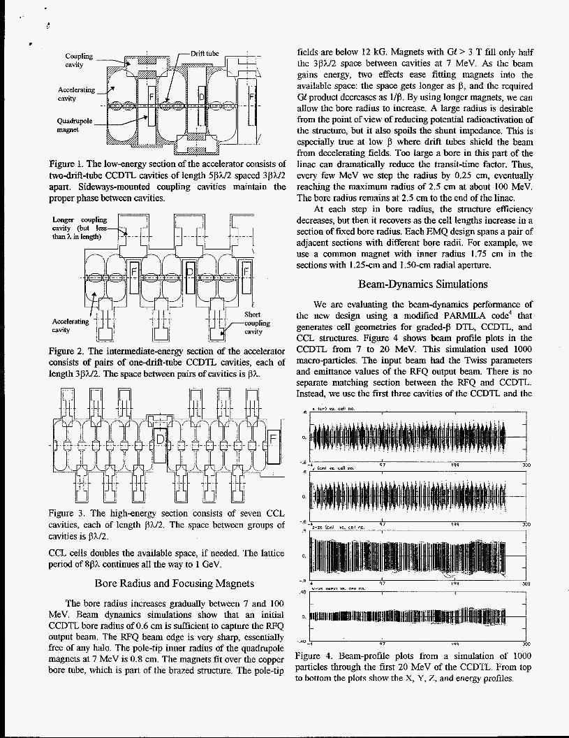
Figure 1. The low-energy section of the accelerator consists of twodrift-tube CCDTL cavities of length 5pW2 spaced 3pW2 apart. Sideways-mounted coupling cavities maintain the proper phase between cavities.
Longer coupling
Figure 2. The intermediate-energy section of the accelerator consists of pairs of onedrift-tube CCDTL cavities, each of length 3pW2. The space between pairs of cavities is J3h.
Figure 3. The high-energy section consists of seven CCL cavities, each of length p3LI2. The space between groups of cavities is pX12.
CCL cells doubles the available space, if needed. The lattice period of 8ph continues all the way to 1 GeV.
Bore Radius and Focusing Magnets
The bore radius increases gradually between 7 and 100 MeV. Beam dynamics simulations show that an initial CCDTL. bore radius of 0.6 cm is sufficient to capture the RFQ output beam. The RFQ beam edge is very sharp, essentially free of any halo. The pole-tip inner radius of the quadrupole magnets at 7 MeV is 0.8 cm. The magnets fit over the copper bore tube, which is part of the brazed structure. The pole-tip
fields are below 12 kG. Magnets with Gf > 3 T fill only half the 3PU2 space between cavities at 7 MeV. As the beam gains energy, two effects ease fitting magnets into the available space: the space gets longer as p, and the required Gf product decreases as Up. By using longer magnets, we can allow the bore radius to increase. A large radius is desirable from the point of view of reducing potential radioactivation of the structure, but it also spoils the shunt impedance. This is especially true at low p where drift tubes shield the beam from decelerating fields. Too large a bore in this part of the linac can dramatically reduce the transit-time factor. Thus, every few MeV we step the radius by 0.25 cm, eventually reaching the maximum radius of 2.5 cm at about 100 MeV. The bore radius remains at 2.5 cm to the end of the linac.
At each step in bore radius, the structure efficiency decreases, but then it recovers as the cell lengths increase in a section of fixed bore radius. Each EMQ design spans a pair of adjacent sections with different bore radii. For example, we use a common magnet with inner radius 1.75 cm in the sections with 1.25-cm and 1.50-cm radial aperture.
Beam-Dynamics Simulations
We are evaluating the beamdynamics performance of the new design using a modified PARMILA code4 that generates cell geometries for graded+ DTL, CCDTL, and CCL structures. Figure 4 shows beam profile plots in the CCDTL from 7 to 20 MeV. This simulation used 1000 macro-particles. The input beam had the Twiss parameters and emittance values of the RFQ output beam. There is no separate matching section between the RFQ and CCDTL. Instead, we use the first three cavities of the CCDTL and the
I[ (cn) *9 cell no I 1 1
0.
I I I I
97 199 300 -.e !.+ y k") C4. sdl no.
3
I I I 4 9 300
I I I
._. . .
--__- 0 7 19'1
Figure 4. Beam-profile plots from a simulation of 1000 particles through the first 20 MeV of the CCDTL. From top to bottom the plots show the X, Y, Z, and energy profiles.

* first few quadrupole magnets to match the beam to the new structure. Both the phase and the accelerating field vary gradually as the beam energy increases from 6.8 to 12 MeV. The synchronous phase ramps from - 6 O O to -30”, and the average accelerating gradient ramps from 0.62 MV/m to 1.5 MV/m. Results show that within statistical error, there is no growth in either transverse or longitudinal emittance.
Redundant Klystrons, RF Module Lengths, and Funneling Options
The rf modules each contain up to 300 total cavities, including the coupling cells. With 300 or fewer cavities and 5 to 6% coupling between cavities, the mode density near the d 2 operating mode remains low enough for easy tuning of the structures. A module is driven by multiple klystrons such that the machine can operate at the design field level with one fewer than the full compliment of klystrons. Conservatively estimating the “real-estate” effective shunt impedance at 25 hrlwm, the structure power is 40 kW/m. For an average energy gain of 1.0 MeVIm, the total power is 140 kW/m for a 100-mA unfunneled system. A typical module uses seven 1- MW klystrons driving about 37 m of structure. The first few rf modules use fewer klystrons because a seven-klystron unit would contain more than 300 cavities. In the unfunneled system, some rf irises are blanked off. A 200-mA funneled system has ten I-MW klystrons driving the same 37-m-long structure. When a klystron fails, a waveguide switch at the appropriate distance from the now unused drive iris prevents loss of rf power from the accelerator into the unused drive line. The machine can continue to operate while the Mystron is repaired or replaced. We have experimentally verified the waveguide-switch technique in a low-power cavity. We are also planning for a high-power test.
The modular design gives flexibility in the choice of energy for funneling, if needed. A single rf module contains several brazed sections joined by flanges. The size of the brazing furnace limits sections to about 2 m in length. An opportunity to break the system for a funnel exists at each flanged section, or roughly every 1 to 2 MeV. Since the field gradient ramps at the low-energy end of the linac, 2 meters corresponds to less than 2.0 MeV at first. The optimum energy for funneling appears to be near 20 MeV. Each leg of CCDTL between 7 and 20 MeV would require oniy three klystrons, including redundancy.
Space for Diagnostics
We provide space for diagnostics in two ways. First, the magnets are as far downstream as possible in the space between accelerating cavities. In some parts of the linac, this by itself provides enough space for diagnostic elements. Second, we can provide additional space, if necessary, by eliminating a cavity at the end of a module. The missing cavity has no effect on the transverse focusing lattice. To mitigate the effect on the longitudinal dynamics, we adjust the coupling between cells before and after the missing cavity
€or a higher end-cell fields to maintain a constant average field gradient. These adjustments eliminate discontinuities in the average “real-estate” longitudinal focusing strength.
Coupling-Cavity Orientation
The accelerator has two coupling-cavity orientations because some sections use half-integral lengths of PA between cavities instead of the more traditional nph spacing, where n is an integer. Figures 1 through 3 show both schemes. This flexibility offers two important advantages. First, it allows changes in the rf cavity type (needed for efficiency) without changing the focusing period. Second, it allows a large ratio of active to total accelerator length. We are testing a sideways mounted coupling cavity on a half-scale, 1400-MHz CCDTL low-power model.
Conclusion
We have outlined a new design for a high-current CW proton linac that has significant mechanical, rf, and beam- dynamics advantages over more conventional designs. The new design has no transitions in the focusing lattice af3er the 7-MeV RFQ. Magnets are not susceptible to drift-tube vibrations because they mount outside the rf structure where they remain accessible and serviceable. Furnace-brazed accelerator modules eliminate the rf and vacuum joints needed in a DTL providing higher reliability for a CW machine. Multiple-klystron rf modules increase reliability and availability. Work continues to refine the design.
References
D. Schrage, L. Young, J. Browman, J. Merson, and A. Naranjo, “Conceptual Design of a 7-MeV RFQ Linac for the Accelerator Production of Tritium,” Los AIamos National Laboratory report LA-TJR-93-1790 (May, 1993).
’5. H. Billen, F. L. Krawczyk, R L. Wood, and L. M. Young, “A New RF Structure for Intermediate-Velocity Particles,” Proceedings of the 1994 International Linac Conference, Vol. 1, p. 341 (August 21-26, 1994).
%. M. Young, “An 8-Meter-Long Coupled Cavity RFQ Linac,” Proceedings of the 1994 International Linac Conference, Vol. 1, p. 341 (August 21-26, 1994).
4H. Takeda and J. E. Stovall, “Modified PARMILA Code for New Accelerating Structures,” this conference.
I