technical terms presentation - orion...
TRANSCRIPT
Technical Terms Presentation July 2013
Airflow/CFM
CFM (Cubic Feet per Minute) indicates the volume of air that a fan will move in one minute at zero static pressure. It is important to note that CFM specifications are stated at zero static pressure because this is the point at which airflow is highest.
Using the CFM specifications of a particular fan you can estimate how many times the air will be "turned over" in your application in 1 minute assuming zero static pressure.
In a home entertainment center with the standard array of equipment you may need to simply "keep the air moving" (1 or 2 times per minute) and can use a smaller, quieter fan. In a cramped server room you may need to turn the air over 10 or 12 times per minute or more. Every application is a little different and only a thermometer placed in the application’s hotspot will tell you whether you need more or less cooling.
Side note: As static pressure increases airflow decreases. CFM is sometimes stated as "m3" (cubic meters per minute) or as "liters per second". Both of these alternate airflow expressions can be translated into CFM.
Airflow/CFM
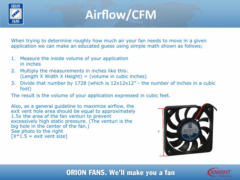
When trying to determine roughly how much air your fan needs to move in a given application we can make an educated guess using simple math shown as follows; 1. Measure the inside volume of your application
in inches 2. Multiply the measurements in inches like this:
(Length X Width X Height) = (volume in cubic inches) 3. Divide that number by 1728 (which is 12x12x12” - the number of inches in a cubic
foot) The result is the volume of your application expressed in cubic feet.
Also, as a general guideline to maximize airflow, the exit vent hole area should be equal to approximately 1.5x the area of the fan venturi to prevent excessively high static pressure. (The venturi is the big hole in the center of the fan.) See photo to the right [X*1.5 = exit vent size]
Speed(RPM)
RPM (Revolutions per Minute) tells the user how many rotations the impeller blade makes in one minute. RPM is not a measure of fan performance by itself as it does not describe any particular performance criteria. Fans cannot be compared effectively against each other using RPM data as equivalent fans can all have the same CFM but different RPM. Side note: Differences in aerodynamic designs have a profound impact on air performance. ORION has improved CFM specifications and Static Pressure measurements on several fan models simply by changing the impeller designs - in one case by as much as 20% - without changing any other specifications, including RPM.
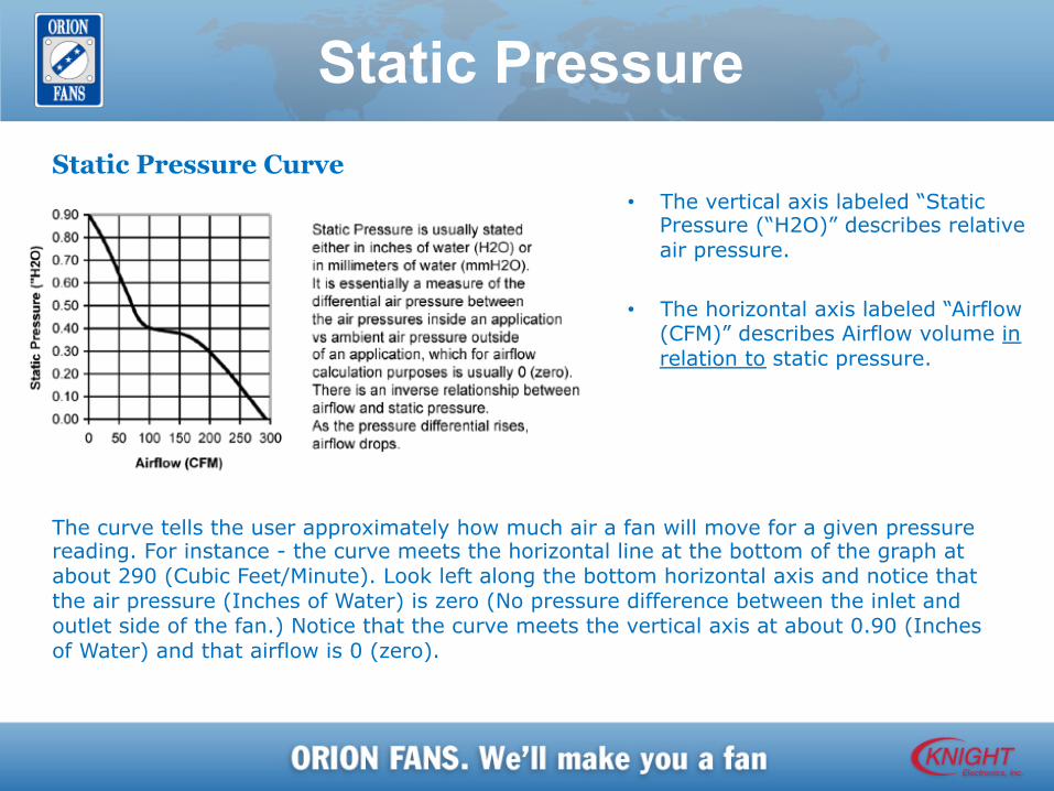
Static Pressure
• The vertical axis labeled “Static Pressure (“H2O)” describes relative air pressure.
• The horizontal axis labeled “Airflow (CFM)” describes Airflow volume in relation to static pressure.
Static Pressure Curve
The curve tells the user approximately how much air a fan will move for a given pressure reading. For instance - the curve meets the horizontal line at the bottom of the graph at about 290 (Cubic Feet/Minute). Look left along the bottom horizontal axis and notice that the air pressure (Inches of Water) is zero (No pressure difference between the inlet and outlet side of the fan.) Notice that the curve meets the vertical axis at about 0.90 (Inches of Water) and that airflow is 0 (zero).
Noise The human ear's response to sound level is roughly logarithmic (based on powers of 10), and the dB scale reflects that fact. An increase of 3dB doubles the sound intensity but a 10dB increase is required before a sound is perceived to be twice as loud by the human ear. Therefore a small increase in decibels represents a large increase in intensity. For example - 10dB is 10 times more intense than 1dB, while 20dB is 100 times more intense than 1dB. The sound intensity multiplies by 10 with every 10dB increase. Following is a list of dB readings from various sources to act as a non-scientific point of reference: 130dB - Jack Hammer (at 5ft) 120dB - Rock Concert /Pain threshold 110dB - Riveter or a Heavy Truck at 50ft 90dB - Heavy Traffic (at 5ft) 85dB – OSHA safety requires hearing protection if exposed to for 8 hour period* 70dB - Department Store or a Noisy Office 50dB - Light Traffic 30dB - Quiet Auditorium 20dB - Faint Whisper (at 5ft) 10dB - Soundproof room/anechoic chamber *OSHA Website https://www.osha.gov/pls/oshaweb/owadisp.show_document?p_table=standards&p_id=9735
Noise (cont.) There are a number of factors that can contribute to the relative noise level of a fan. In terms of raw numbers our fans are tested in free air (zero static pressure) with the noise sensor positioned one meter from the outlet side of the fan in an anechoic chamber. There are several factors that could affect the noise characteristics of your fan and make it seem louder than it is... or needs to be: 1. Inadequate venting: The efficiency of the fan is degraded by having to overcome a pressure differential. It decreases the effectiveness of the impeller, causes noise (dB) to increase and causes Airflow (CFM) to drop. Increasing the vent area to 1.5x the fan venturi should alleviate the noise if this is the problem. 2. Airflow obstructions: If there is an obstacle such as a PC board or light ballast within an inch or two of the fan inlet or outlet and directly in the airstream this can cause a localized increase (between the impeller and the obstruction) in static pressure. The effect is the same as if there was inadequate venting generally and can cause an increase in noise. 3. Vibration: Often this is due to loose mounting screws. Other times it is caused by the fan being mounted on a thin metal, laminate or wooden surface. The fan will vibrate against the surface and the surface can act like a sound board, amplifying otherwise soft noise. This problem can often be solved by adding plastic or rubber grommets between the fan and mounting surface and which are commonly available at most home improvement stores. 4. Balance or bearing issues: Rattles, hums, squeals or clicking are usually balance or bearing issues. If your fan is a few years old and has been run more or less continuously, then the bearings may simply be worn out.
Ball Bearings
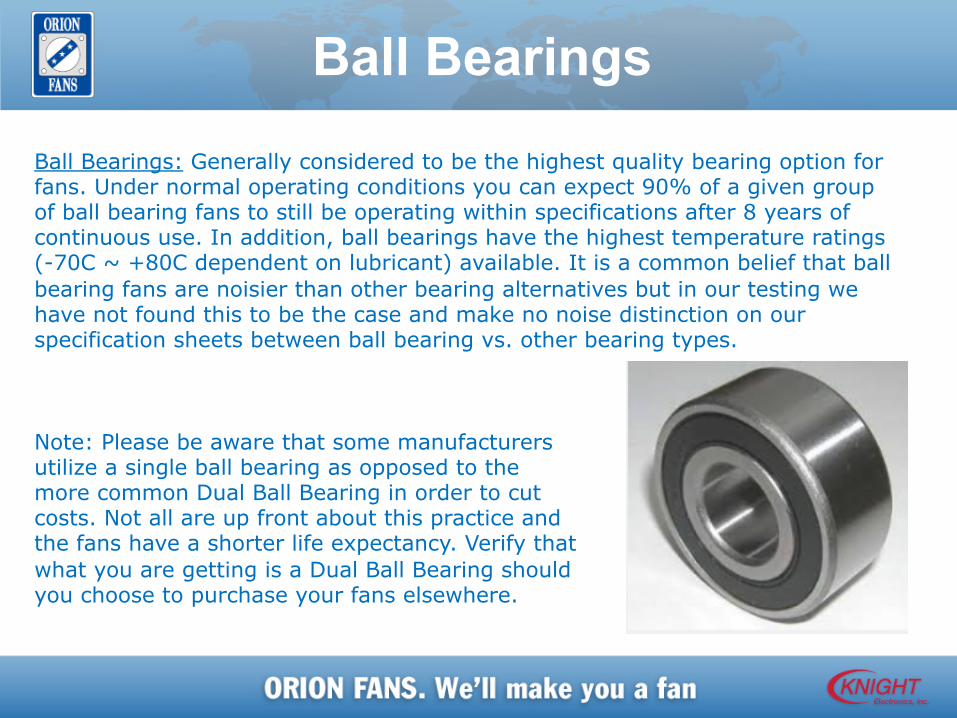
Ball Bearings: Generally considered to be the highest quality bearing option for fans. Under normal operating conditions you can expect 90% of a given group of ball bearing fans to still be operating within specifications after 8 years of continuous use. In addition, ball bearings have the highest temperature ratings (-70C ~ +80C dependent on lubricant) available. It is a common belief that ball bearing fans are noisier than other bearing alternatives but in our testing we have not found this to be the case and make no noise distinction on our specification sheets between ball bearing vs. other bearing types. Note: Please be aware that some manufacturers utilize a single ball bearing as opposed to the more common Dual Ball Bearing in order to cut costs. Not all are up front about this practice and the fans have a shorter life expectancy. Verify that what you are getting is a Dual Ball Bearing should you choose to purchase your fans elsewhere.
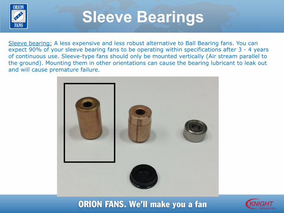
Sleeve Bearings Sleeve bearing: A less expensive and less robust alternative to Ball Bearing fans. You can expect 90% of your sleeve bearing fans to be operating within specifications after 3 - 4 years of continuous use. Sleeve-type fans should only be mounted vertically (Air stream parallel to the ground). Mounting them in other orientations can cause the bearing lubricant to leak out and will cause premature failure.

Sealed Sleeve Bearings Sealed Sleeve Bearing: Several manufacturers including ORION FANS have added this type to their list of bearing options. Essentially this is a standard Sleeve Bearing with an oil collection cup that catches the lubricant as it exits the bearing and recirculates it back into the fan thereby extending the fan life. It is slightly more expensive than a standard sleeve and slightly less expensive than a ball bearing and has a life expectancy somewhere between the two.
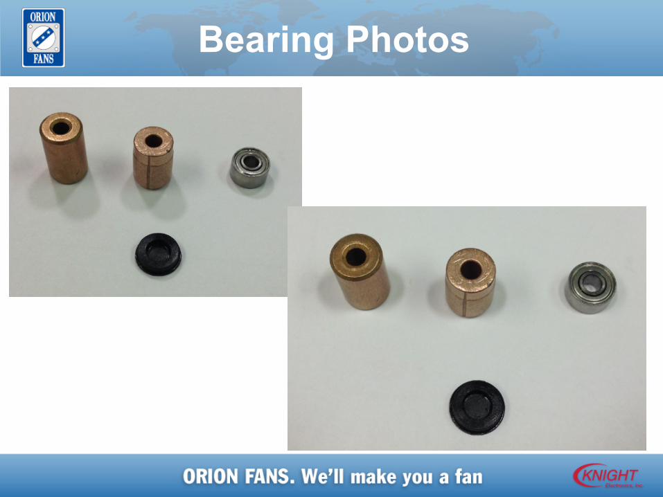
Bearing Photos
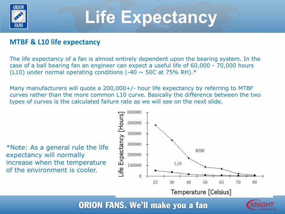
Life Expectancy MTBF&L10lifeexpectancy The life expectancy of a fan is almost entirely dependent upon the bearing system. In the case of a ball bearing fan an engineer can expect a useful life of 60,000 - 70,000 hours (L10) under normal operating conditions (-40 ~ 50C at 75% RH).* Many manufacturers will quote a 200,000+/- hour life expectancy by referring to MTBF curves rather than the more common L10 curve. Basically the difference between the two types of curves is the calculated failure rate as we will see on the next slide.
*Note: As a general rule the life expectancy will normally increase when the temperature of the environment is cooler.
Life Expectancy(cont.)
MTBF&L10lifeexpectancy L10: Specifically refers to the amount of time it takes for 10% of a group of fans to fail during testing. Stated another way: at the end of the specified life expectancy, 90% of a given fan population will still be operating within stated specifications. MTBF: (Mean Time Before Failure) as it relates to the fan industry refers to a 50% failure rate. MTBF calculations as provided by most fan manufacturers are actually "L50" calculations. That is to say that at the end of the stated life expectancy at least one half of a given population of fans will have failed.
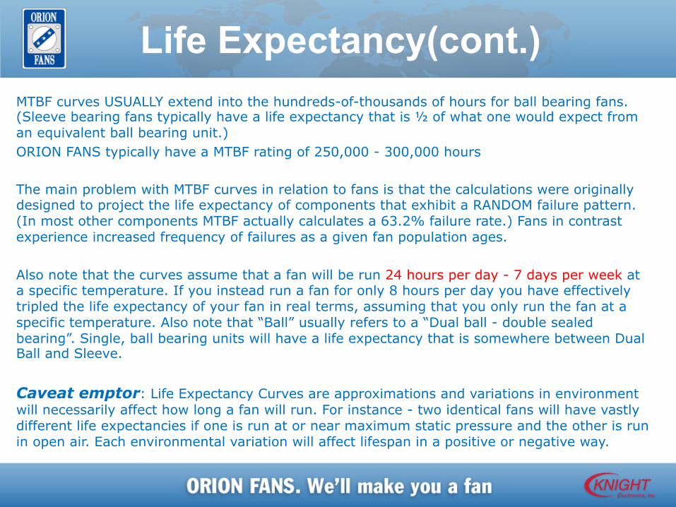
Life Expectancy(cont.) MTBF curves USUALLY extend into the hundreds-of-thousands of hours for ball bearing fans. (Sleeve bearing fans typically have a life expectancy that is ½ of what one would expect from an equivalent ball bearing unit.) ORION FANS typically have a MTBF rating of 250,000 - 300,000 hours The main problem with MTBF curves in relation to fans is that the calculations were originally designed to project the life expectancy of components that exhibit a RANDOM failure pattern. (In most other components MTBF actually calculates a 63.2% failure rate.) Fans in contrast experience increased frequency of failures as a given fan population ages. Also note that the curves assume that a fan will be run 24 hours per day - 7 days per week at a specific temperature. If you instead run a fan for only 8 hours per day you have effectively tripled the life expectancy of your fan in real terms, assuming that you only run the fan at a specific temperature. Also note that “Ball” usually refers to a “Dual ball - double sealed bearing”. Single, ball bearing units will have a life expectancy that is somewhere between Dual Ball and Sleeve. Caveat emptor: Life Expectancy Curves are approximations and variations in environment will necessarily affect how long a fan will run. For instance - two identical fans will have vastly different life expectancies if one is run at or near maximum static pressure and the other is run in open air. Each environmental variation will affect lifespan in a positive or negative way.
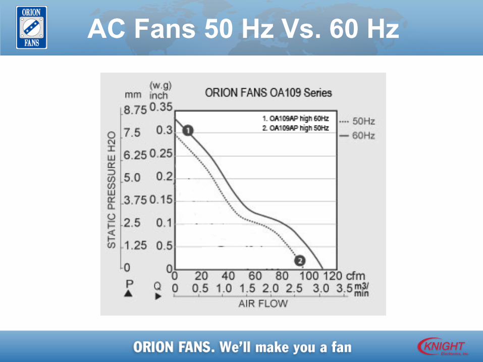
AC Fans 50 Hz Vs. 60 Hz
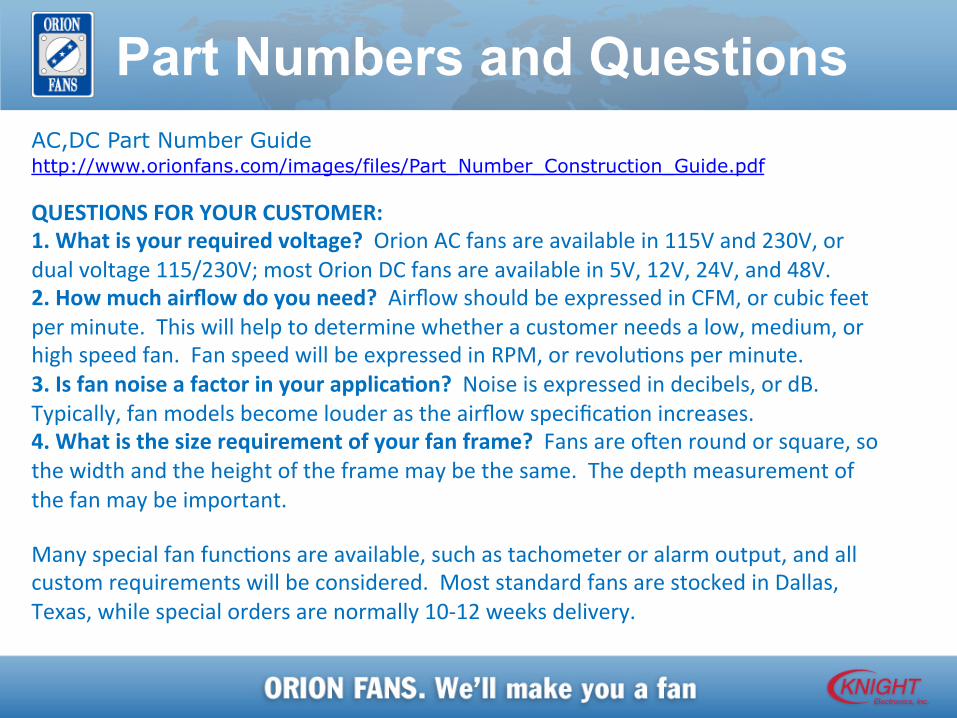
Part Numbers and Questions AC,DC Part Number Guide http://www.orionfans.com/images/files/Part_Number_Construction_Guide.pdf QUESTIONSFORYOURCUSTOMER:1.Whatisyourrequiredvoltage?OrionACfansareavailablein115Vand230V,ordualvoltage115/230V;mostOrionDCfansareavailablein5V,12V,24V,and48V.2.Howmuchairflowdoyouneed?AirflowshouldbeexpressedinCFM,orcubicfeetperminute.Thiswillhelptodeterminewhetheracustomerneedsalow,medium,orhighspeedfan.FanspeedwillbeexpressedinRPM,orrevoluMonsperminute.3.IsfannoiseafactorinyourapplicaTon?Noiseisexpressedindecibels,ordB.Typically,fanmodelsbecomelouderastheairflowspecificaMonincreases.4.Whatisthesizerequirementofyourfanframe?FansareoRenroundorsquare,sothewidthandtheheightoftheframemaybethesame.Thedepthmeasurementofthefanmaybeimportant.
ManyspecialfanfuncMonsareavailable,suchastachometeroralarmoutput,andallcustomrequirementswillbeconsidered.MoststandardfansarestockedinDallas,Texas,whilespecialordersarenormally10-12weeksdelivery.
Headquarters

Fans, Fan Trays, Accessories, Blowers
Thank you for letting us
make you a fan
KnightElectronics10557MetricDrive www.orionfans.comDallas,TX75243800.323.0265