technical summary for aspen pumps - hvacquick - · pdf filetechnical summary for aspen pumps...
TRANSCRIPT
20
Technical Summary for Aspen pumps
Minipumps are not designed to run dry as they are both cooled and lubricated by the water flowing through them. They require a float switch to detect the presence of water in the drain pan and activate the pump only when water is present.
Minipumps always consists of two elements:1. Pump body - Includes an electronic PCB and the pump motor.2. Reservoir - Contains the filter and the switching mechanism to activate the pump. This must alwaysbe kept level and clean for proper operation of the float switch. The filter must be cleaned regularly.
Minipumps are available in two styles:1. Split type - (Orange or Aqua series) are designed with separate pump and reservoir. The 2 elements are connected together with a length of 1/4” id vinyl tube and a communication cable, both of which are usually around 6 feet long. On our orange series pumps, this may be extended if required. 2. Monobloc type - (Lime or White series) are designed with both the pump and reservoir as one integral unit, sharing a common body. No connecting tubes or wires are needed.
Minipumps have two cable connections: 1. Power supply cable - color coded for different voltages. Conductors for 115 volt pumps are white, black and green, and conductors for 230 volt and univolt pumps are red, black and green, and these colors are standard for all models which operate on line voltage.2. Overflow switch cable - designed to break the communication wire between the condenser and the evaporator in case the water level in the reservoir rises to an unacceptable level. This cable has 3 conductors, gray (common), purple (normally closed) and orange (normally open, generally not used). This color coding is identical for all pump models except the Mini White which has gray and purple only. During overflow condi-tion, pump will continue to operate.Connection of the overflow switch is mandatory.
NOTE: The overflow switch uses dry contacts rated 5 amperes @ 230vac. Communication circuits are usually well below this rating. If a higher rating is desired, an external relay may be added. The pump must remain powered for the overflow switch to operate when required. Factory approved wiring diagrams for most minisplts are available at www.airtecproducts.com
Some minisplits have communication wires which are sensitive. They utilize proprietary operating protocols and may need to be wired differently. In these cases, the overflow switch must be wired according to a specific wiring diagram dedicated to that particular manufacturer and/or model series
Peristaltic pumps offer three major benefits for minisplit applications.1. The ability to run both wet and dry, enables intermittent operation with a reservoir and float switch or continuous with the evaporator. 2. The capability to pump contaminates washed from the evaporator coil during condensate production.3. A High level of suction enables remote mounting up to 40 feet away from the evaporator.
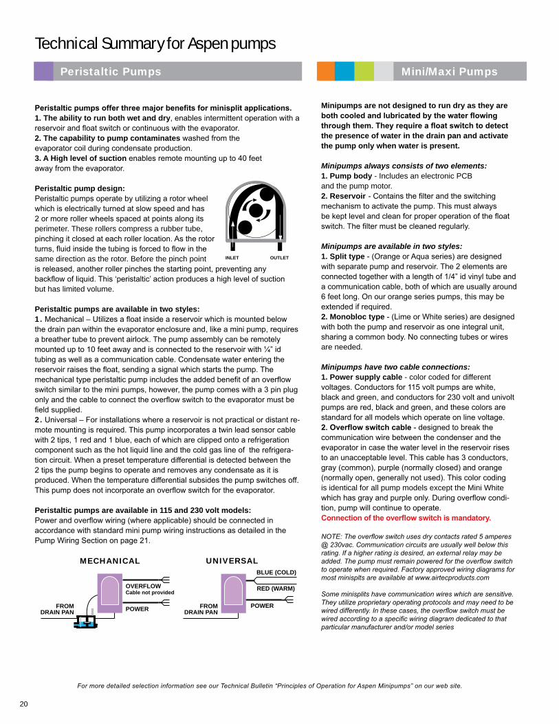
Peristaltic pump design:Peristaltic pumps operate by utilizing a rotor wheel which is electrically turned at slow speed and has 2 or more roller wheels spaced at points along its perimeter. These rollers compress a rubber tube, pinching it closed at each roller location. As the rotor turns, fluid inside the tubing is forced to flow in the same direction as the rotor. Before the pinch point is released, another roller pinches the starting point, preventing any backflow of liquid. This ‘peristaltic’ action produces a high level of suction but has limited volume.
Peristaltic pumps are available in two styles:1. Mechanical – Utilizes a float inside a reservoir which is mounted below the drain pan within the evaporator enclosure and, like a mini pump, requires a breather tube to prevent airlock. The pump assembly can be remotely mounted up to 10 feet away and is connected to the reservoir with ¼” id tubing as well as a communication cable. Condensate water entering the reservoir raises the float, sending a signal which starts the pump. The mechanical type peristaltic pump includes the added benefit of an overflow switch similar to the mini pumps, however, the pump comes with a 3 pin plug only and the cable to connect the overflow switch to the evaporator must be field supplied.2. Universal – For installations where a reservoir is not practical or distant re-mote mounting is required. This pump incorporates a twin lead sensor cable with 2 tips, 1 red and 1 blue, each of which are clipped onto a refrigeration component such as the hot liquid line and the cold gas line of the refrigera-tion circuit. When a preset temperature differential is detected between the 2 tips the pump begins to operate and removes any condensate as it is produced. When the temperature differential subsides the pump switches off. This pump does not incorporate an overflow switch for the evaporator.
Peristaltic pumps are available in 115 and 230 volt models:Power and overflow wiring (where applicable) should be connected in accordance with standard mini pump wiring instructions as detailed in the Pump Wiring Section on page 21.
Mini/Maxi PumpsPeristaltic Pumps
INLET OUTLET
POWER
BLUE (COLD)
UNIVERSAL
RED (WARM)
FROMDRAIN PAN
FROMDRAIN PAN
MECHANICAL
POWER
OVERFLOWCable not provided
For more detailed selection information see our Technical Bulletin “Principles of Operation for Aspen Minipumps” on our web site.
21
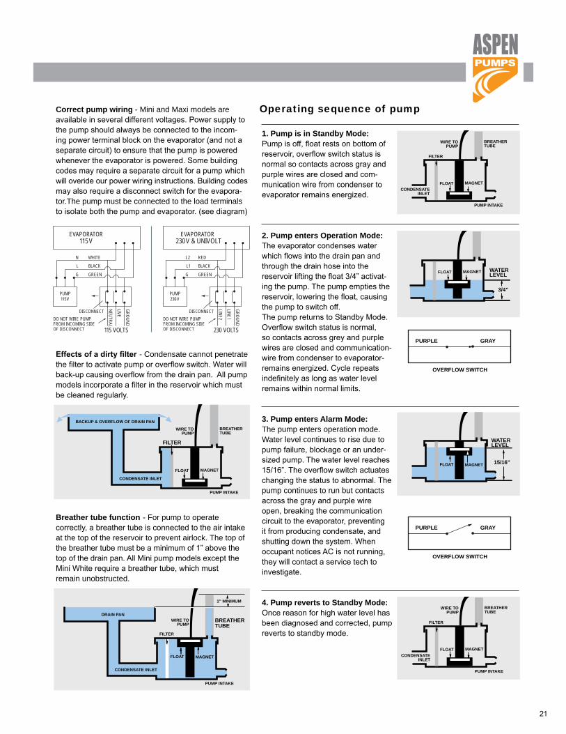
Correct pump wiring - Mini and Maxi models are available in several different voltages. Power supply to the pump should always be connected to the incom-ing power terminal block on the evaporator (and not a separate circuit) to ensure that the pump is powered whenever the evaporator is powered. Some building codes may require a separate circuit for a pump which will overide our power wiring instructions. Building codes may also require a disconnect switch for the evapora-tor.The pump must be connected to the load terminals to isolate both the pump and evaporator. (see diagram)
Effects of a dirty filter - Condensate cannot penetrate the filter to activate pump or overflow switch. Water will back-up causing overflow from the drain pan. All pump models incorporate a filter in the reservoir which must be cleaned regularly.
Breather tube function - For pump to operate correctly, a breather tube is connected to the air intake at the top of the reservoir to prevent airlock. The top of the breather tube must be a minimum of 1” above the top of the drain pan. All Mini pump models except the Mini White require a breather tube, which must remain unobstructed.
1. Pump is in Standby Mode:Pump is off, float rests on bottom of reservoir, overflow switch status is normal so contacts across gray and purple wires are closed and com-munication wire from condenser to evaporator remains energized.
2. Pump enters Operation Mode:The evaporator condenses water which flows into the drain pan and through the drain hose into thereservoir lifting the float 3/4” activat-ing the pump. The pump empties the reservoir, lowering the float, causing the pump to switch off. The pump returns to Standby Mode.Overflow switch status is normal, so contacts across grey and purple wires are closed and communication-wire from condenser to evaporator-remains energized. Cycle repeats indefinitely as long as water level remains within normal limits.
3. Pump enters Alarm Mode:The pump enters operation mode.Water level continues to rise due to pump failure, blockage or an under-sized pump. The water level reaches 15/16”. The overflow switch actuates changing the status to abnormal. The pump continues to run but contacts across the gray and purple wire open, breaking the communication circuit to the evaporator, preventing it from producing condensate, and shutting down the system. When occupant notices AC is not running, they will contact a service tech to investigate.
4. Pump reverts to Standby Mode:Once reason for high water level has been diagnosed and corrected, pump reverts to standby mode.
Operating sequence of pump
FLOAT MAGNET WATERLEVEL
3/4”
FLOAT MAGNET
WATERLEVEL
15/16”
WIRE TOPUMP
FILTER
FLOAT MAGNET
PUMP INTAKE
CONDENSATEINLET
CONDENSATEINLET
BREATHERTUBE
WIRE TOPUMP
FILTER
FLOAT MAGNET
PUMP INTAKE
BREATHERTUBE
1
2
3
4
FLOAT MAGNET WATERLEVEL
3/4”
FLOAT MAGNET
WATERLEVEL
15/16”
WIRE TOPUMP
FILTER
FLOAT MAGNET
PUMP INTAKE
CONDENSATEINLET
CONDENSATEINLET
BREATHERTUBE
WIRE TOPUMP
FILTER
FLOAT MAGNET
PUMP INTAKE
BREATHERTUBE
1
2
3
4
FLOAT MAGNET WATERLEVEL
3/4”
FLOAT MAGNET
WATERLEVEL
15/16”
WIRE TOPUMP
FILTER
FLOAT MAGNET
PUMP INTAKE
CONDENSATEINLET
CONDENSATEINLET
BREATHERTUBE
WIRE TOPUMP
FILTER
FLOAT MAGNET
PUMP INTAKE
BREATHERTUBE
1
2
3
4
FLOAT MAGNET WATERLEVEL
3/4”
FLOAT MAGNET
WATERLEVEL
15/16”
WIRE TOPUMP
FILTER
FLOAT MAGNET
PUMP INTAKE
CONDENSATEINLET
CONDENSATEINLET
BREATHERTUBE
WIRE TOPUMP
FILTER
FLOAT MAGNET
PUMP INTAKE
BREATHERTUBE
1
2
3
4
WIRE TOPUMP
FLOAT MAGNET
PUMP INTAKE
CONDENSATE INLET
BREATHERTUBE
BACKUP & OVERFLOW OF DRAIN PAN
WIRE TOPUMP
PUMP INTAKE
CONDENSATE INLET
BREATHERTUBE
1” MINIMUM
DRAIN PAN
FLOAT MAGNET
FILTER
FILTER
WIRE TOPUMP
FLOAT MAGNET
PUMP INTAKE
CONDENSATE INLET
BREATHERTUBE
BACKUP & OVERFLOW OF DRAIN PAN
WIRE TOPUMP
PUMP INTAKE
CONDENSATE INLET
BREATHERTUBE
1” MINIMUM
DRAIN PAN
FLOAT MAGNET
FILTER
FILTER
PUMP115V
115 VOLTS
EVAPORATOR115V
GREEN
DISCONNECTDO NOT WIRE PUMPFROM INCOMING SIDEOF DISCONNECT
BLACK
WHITE
G
L
N
NEUTRAL
LIVE
GROUND
PUMP230V
230 VOLTS
EVAPORATOR230V & UNIVOLT
GREEN
DISCONNECTDO NOT WIRE PUMPFROM INCOMING SIDEOF DISCONNECT
BLACK
RED
G
L1
L2
LINE2
LINE1
GROUND
PURPLE GRAY
OVERFLOW SWITCH
PURPLE GRAY
OVERFLOW SWITCH
PURPLE GRAY
OVERFLOW SWITCH
PURPLE GRAY
OVERFLOW SWITCH