technical specification maintainence ... - benson...
TRANSCRIPT

1
TECHNICAL SPECIFICATION MAINTAINENCE , ASSEMBLY
USER INSTRUCTIONS Modular Air Conditioning Appliances with Scroll
compressor and R407C refrigeration gas
External Unit B-CF
BENSON HEATING LUDLOW ROAD KNIGHTON
POWYS. LD7 1LP
UK Benson Heating is a Division of Benson Climate Systems Ltd
2
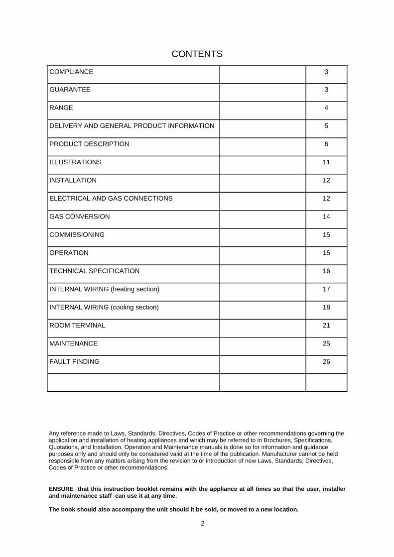
COMPLIANCE 3
GUARANTEE 3
RANGE 4
DELIVERY AND GENERAL PRODUCT INFORMATION 5
PRODUCT DESCRIPTION 6
ILLUSTRATIONS 11
INSTALLATION 12
ELECTRICAL AND GAS CONNECTIONS 12
GAS CONVERSION 14
COMMISSIONING 15
OPERATION 15
TECHNICAL SPECIFICATION 16
INTERNAL WIRING (heating section) 17
INTERNAL WIRING (cooling section) 18
ROOM TERMINAL 21
MAINTENANCE 25
FAULT FINDING 26
CONTENTS
Any reference made to Laws, Standards, Directives, Codes of Practice or other recommendations governing the application and installation of heating appliances and which may be referred to in Brochures, Specifications, Quotations, and Installation, Operation and Maintenance manuals is done so for information and guidance purposes only and should only be considered valid at the time of the publication. Manufacturer cannot be held responsible from any matters arising from the revision to or introduction of new Laws, Standards, Directives, Codes of Practice or other recommendations. ENSURE that this instruction booklet remains with the appliance at all times so that the user, installer and maintenance staff can use it at any time. The book should also accompany the unit should it be sold, or moved to a new location.

3
Compliance The Benson B-CF range of conditioning units detailed herewith are manufactured for Benson Heating within the parameters of ISO 9002. The Benson B-CF range has been independently tested and assessed, and has been found to meet the Essential Requirement of the following European Directives: Gas appliance Directive (90/396/EEC) Machinery Directive (89/392/EEC) 91368/EEC 93/44/EEC 93/65/EEC Low Voltage Directive (73/23/EEC Electromagnetic Compatibility Directive (98/336/EEC and 91/31/EEC) Product Liability Directive (65/374/EEC) The manufacturer has taken reasonable and practical steps to ensure that Benson B-CF range is safe and without risk when properly used. These units should therefore only be used in the manner and purpose for which they were intended, and in accordance with the recommendations detailed herewith. The units have been designed manufactured, assembled, inspected, and tested, with safety and quality in mind, there are certain basic precautions which the installer and user should be aware of, and they are strongly advised to read the appropriate sections of the information pack accompanying the unit, prior to installation or use. Benson Heating supports all new products being supplied to their customers with a comprehensive information pack; this clearly defines mandatory instructions for the safe installation, use, and maintenance, of the appliance(s). Where proprietary items are incorporated into Benson Heating products, detailed information and instructions are also provided as part of the information pack. It is the responsibility of the installer, owner, user, or hirer, of such products supplied by Benson Heating, to ensure that they are familiar with the appropriate information/manuals, supplied by the manufacturer, and that they are suitably aware of the purpose of the manuals and the safety instructions. In addition, operators must be suitably trained in the use of the appliance so as to ensure its continued safe and efficient use. Benson Heating has a commitment to continuous improvement, and therefore reserves the right to amend or change the specification of the B-CF range subject to agreement from The Notified Body. Contained within the text of the manual, the words 'Caution' and 'Warning' are used to highlight certain points. Caution is used when failure to follow or implement the instruction(s) can lead to premature failure or damage to the heater or its component parts.
Warning is used when failure to heed or implement the instruction(s) can lead to not only component damage, but also to a hazardous situation being created where there is a risk of personal injury. Guarantee The B-CF is supplied with a 2 year warranty on all parts. In addition to this there is also a 10 year time related warranty on the combustion chamber. The warranty commences from the date of despatch from the manufacturer, and is subject to the terms detailed within the manufacturer 'conditions of business'. The warranty may be invalidated if: a) The warranty registration/commissioning card has not been completed and returned to the manufacturer b) The installation is not in accordance with the general requirements of this manual c) The flue arrangement and air supply for the units are not in accordance with the manufacturers recommendations, codes of practice, or similar standards d) Air flow through the units is not in accordance with the manufacturers technical specifications e) Internal wiring on the units has been tampered with or unauthorised service/repairs undertaken f) The main electrical supply input to the units has been interrupted during the operating mode g) The unit has been subject to and affected by the ingress of water in any form h) The unit is not operated at the rating(s) laid down in the manufacturers technical specifications i) The unit has not been operated or used within the normal scope of its intended application j) The manufacturer's recommended minimum service requirements have not been complied with All warranty claims must contain the following information to enable processing to take place; (1) Unit model (2) Unit serial number (3) Order reference/date of order, together with full installation details (name and address) (4) Details or symptoms of fault (5) Installers name and address. Faulty parts must be returned to the manufacturer Spares Department, the address of which is provided on the rear cover of this manual. Any such parts will undergo inspection to verify the claim. Replacement parts supplied prior to this may be charged, and a credit supplied upon subsequent validation of the warranty claim. Consumable items are specifically not included within the scope of the warranty. Notification is required immediately a fault is suspected. The manufacturer will not accept responsibility for any additional damage that has been caused, expense incurred, or consequential loss resulting from any failure of the units). Ensure that the unit is able to operate within the parameters shown on the data plate and the technical data within the manual. Incorrect gas settings may lead to condensation within the combustion if to low, and overheating if to high both will cause damage to the heat exchanger.

4
IMPORTANT NOTICE TO INSTALLERS
Installers should satisfy themselves that the gas pipework installation is carried out in accordance with all current legislation, Codes of Practice and recommendations . Additionally it may be necessary to protect the gas valves which form part of the heater or burner assembly from potential pipe contamination particularly, but not exclusively , where copper gas pipework is used. In instances where copper pipework is to be used for all or part of a gas pipework installation, including short length final connections then we advise that installers consult with gas supplier or provider and satisfy themselves what additional precautions may be necessary

5
Delivery and pre-installation checks. The Unit is supplied wrapped in heavy-duty protective polythene. On receipt of the heater, the following checks should be carried out; a) The model is as per order b) That it is undamaged c) That it is suitable for the gas supply d) That it is suitable for the electrical supply Warning Unauthorised modifications to the appliance, or departure from the manufacturers guidance on intended use, or, installation contrary to the manufacturers recommendations may constitute a hazard. Note To ignore the warning and caution notices, and to ignore the advice from the manufacturer on installation, commissioning, servicing, or use, will jeopardise any applicable warranty, moreover, such a situation could also compromise the safe and efficient running of the appliance itself, and thereby constitute a hazard. The manufacturer has taken reasonable and practical steps to ensure that Benson B-CF units are safe and without risk when properly used. These units should therefore only be used in the manner and purpose for which they were intended, and in accordance with the recommendations detailed herewith. These appliances have been produced for room air conditioning and/or heating and should only be used for this purpose Should a leak of refrigeration liquid occur , Switch the system to “OFF” and Isolate the Gas supply . The appliance contains refrigerating gas; care should be taken not to damage the gas circuit and condenser. A suitable room temperature should be maintained at all times for the economic operation of the unit, avoid temperature fluctuation. Do not leave rooms closed for long periods. Periodic opening of windows or doors to refresh the air is recommended. Isolate the appliance if it is not to be used for long periods of time, The installation of the appliance must meet all the relevant European, national, and local criteria. Prior to installation the following points should be considered; a) The position of the unit for the optimum efficient distribution and circulation of air b) The position of the unit relative to the route of the flue if extension is required
c) The position of the unit relative to the supply of gas d) The position of the unit relative to the electrical services, and if appropriate, any additional controls. e) The position of the unit relative to the supply of fresh air f) The position of the unit relative to service and maintenance requirements Caution Ensure that the gas service to the appliance carries the correct gas type and that the supply pressure is in accordance with the supply type and pressure stated on the data plate. The unit must not be installed within an area where the conditions are unsuitable, e.g. where the atmosphere is highly corrosive, has a high degree of salinity, or where high wind velocities may affect burner operation. Suitable protection should be provided for the appliance when it is located in a position where it may be susceptible to external mechanical damage The appliance should only be operated by suitably qualified personnel only. Before carrying out any maintenance operation, the appliance must be ISOLATED from the mains supply and the main switch set to “OFF” Safety and control devices must not be modified in any way without the authorisation of the manufacturer of the appliance. Care should be taken with electrical cables on the appliance, ensure the wiring cannot make contact with surfaces liable to be subject to high temperatures avoid do not pull electrical cables even if disconnected from the mains supply. Do not remove access panels on the appliance, without having first set the mains switch to “OFF”. General product information Over recent years, plant monitoring costs have soared due to an increase in labour and financial costs. In the air conditioning sector in particular, traditional systems still require remarkable volumes, resources and manufacturing times. In response Air Conditioners like the External Unit, a modular unit for positioning outside or on roofs making the most of our great experience in both sectors of air conditioning. External Units are able to produce cold air for air conditioning, using R407C as refrigerating fluid, which guarantees particular advantages from an ecological point of view: in fact it does not contains no chlorine, it has a very low HGWP value and a zero ODP.

6
The heating section of the unit has been manufactured with multigas atmospheric burners, combined with patented, stainless steel heat exchangers with a large surface area ,which ensure high heating performances, above 90%. The External Units, for single zone air conditioning and heating, are supplied completely assembled (air, heating, refrigerating, electrical systems), tested prior to despatch. The units are fitted with provision for forklift handling . which can also be used as practical lifting eyes, for ease of handling on site. The appliance is made of suitable weather proof material to allow for external operation . Inside, they use a scroll compressor assembled onto anti-vibrating supports and placed in a special compartment, the fans used in the condensation compartments, can have, as an option, an electronically controlled variable speed, so as to ensure minimum noise disturbance when in operation. The appliances are equipped with safety devices, pressure gauges, and sensors for protection of the main controls. Microprocessor electronic equipment controls and regulates the unit when in operation . The range of units are suitable for operation on small, medium and large systems, for heating residential, commercial and industrial environments. As the appliance does both heating and air conditioning it eliminates the need for separate appliances for each operation there by reducing the costs . All appliances undergo a rigorous test programme prior to being despatched, whilst such a programme does involve pre-commissioning and setting up the unit to operate efficiently and well within its designed operational limits, this does not mean that on site commissioning is less important than might otherwise be the case. Note It is strongly recommended that equipment used for the sampling and analysis of flue gases is accurate to within +/- 0.1% and maintained so that it is regularly calibrated. External Units leave the factory completely assembled, pre filled with R407C refrigerating gas, tested and approved by an ISO 9002 Company System Quality certificate. Large and efficient condenser coils permit low condensation temperatures and low compression ratio with subsequent low absorption of electrical energy. A sub-cooling circuit is inserted into each coil for increasing the refrigerating power, without additional use of electrical energy for the compressor. The wide sections for the passage of conditioned air mean low resistance and therefore lower electrical energy employed by the fan motor. The appliance is designed for carrying out, air conditioning in the summer period, and also has a fan only option for blowing fresh air by adjusting the external air vents for ventilation only for the areas in use. The controls include automatic compensation of the
room set-point on the variation of external temperatures and proportional + integral regulation algorithms enabling best environmental management and comfort. As the unit has independent operation of the heating and cooling systems when the room set-point is reached, the unit will operate more economically, this is done by gradually reducing the number of pre set start-ups, and thus maintaining a better environmental temperature. The Unit is specially designed with a heating section, and is able to heat air in the environment using the heat energy produced by combustion process. Heat is produced by blowing the ambient air over a heat exchanger with a centrifugal fan. Once the heat exchange has taken place the products of combustion are expelled to the outside by a flue venter fan which enables the appliance to operate without it even having to be connected up to a chimney. This system permits significant savings in terms of the cost of the system and ensures economic running, making it particularly suitable for buildings where an intermittent and occasional use is foreseen. Since the combustion air intake is on the outside, the combustion circuit of the air heater becomes watertight and this enables these appliances to be used for the heating of varied environments (churches, gyms, shops etc.). The whole unit is completely and carefully insulated on the inside to limit energy waste. The wiring (and safety in general) is in compliance with C.E. I. EN 60335-2-40 standard, the electrical control board is big and has a large access, ensuring ease of maintenance. Microprocessor logic, safety thermostat, fuses on the electrical circuits and a phase rotation device , protect the unit against any abnormal operating conditions. Microprocessor logic are characterised by a remote room terminal which electronically communicates with the output board, simplifying check and maintenance procedures. Three-phase fuses on the fan and compressor motors and an isolation switch complete the protection against short circuits, loss of a phase and fan lockout conditions. Each electrical component is identified with a label and conductors are coded with colours and numbers. The double compressor units enable service on one circuit whilst the other is in operation. All functional and safety controls are concentrated in one place. Low air speed on the air filters, due to their large surface area , enable long intervals between changes under normal . The large access doors on each side have hinges and a simple opening system. The fans have self-lubricating ball bearings, suitable for over 200,000 hours.

7
Construction The casing is constructed from galvanised sheet iron and varnished with a cataphoresis treatment in order to ensure complete resistance against the weather. Special guides for the forks facilitate delivery and handling on site; they also act as practical lifting eyes for cables and chains and can be used for keeping the unit secure during transportation. The internal insulation, comprises of glass wool panels covered with aluminium film for the radiating surfaces, and with foamed polyurethane covered with a washable film for the surfaces which are in contact with the treated air, The panelling is designed to be watertight . REFRIGERATION Condensing section The compressors are reliable, scroll type, with a three-phase motor, protected against wrong rotation direction by means of a phase rotation detector. A protection for overload and loss of phase for the electric motor is incorporated into single rated power models up to 10 hp, and it is the electronic type in larger appliances. Special hard rubber buffers are supplied, to minimise vibration transmission to the work place. Each compressor is supplied with complete microprocessor logic controls and independent fridge circuit, which includes flow/humidity light, filter/drier and high and low pressure gauge. The coils are of the 2 or 3 rank type, with a large frontal surface, in order to permit working at low condensation temperatures and so as to limit the use of electrical energy. For extra system efficiency, each condenser includes a pre-cooling circuit. The fan of each fridge circuit operates independently from the other, enabling reliability, as well as containing of partial load absorption: an optional continuous and reliable condensation temperature control is available. The helicoidal fans are of vertical discharge type, to minimise noise transmission towards the building. The IP66 fan motors are internally protected against overload and loss of a phase. The compressor compartment and related components and pipes are easily accessible.
Evaporating section The front section is wide enough to enable a large variation in air delivery, without condensation water carry over and it has a low internal static pressure drop. The double compressor units have heat exchangers with circuits designed in such a way that they use the whole front surface, and the whole depth of the finned pack, in order to maximise dehumidifying and to eliminate air stratifications at partial load as well. The condensation collecting tank is sealed with sealant to minimise the risks of leaks. The whole section is thermally and acoustically insulated with washable panels.

8
Legend
Compressor High Limit Sensor (140°C) High pressure gauge (26,9 bar) Low pressure gauge (2 bar) Filter Indicator Thermostatic expansion valve Evaporator Condenser
SCHEMATIC Refrigeration Section

9
HEATING The choice of positioning this section on the fan delivery enables both the safeguarding of the motor as well as residual noise abatement before the pressing mouth of the unit, especially in those applications which require greater working static pressure. The exchanger is patented and made of stainless steel, it is single-step on the smoke side, cross flow on the air one. It is suitable for gas and is characterised by its high efficiency and virtually non-existing maintenance. It is built with welded steel plate, its sealing qualities being tested as per the UNI CIG 9462 standards, easy to inspect for normal cleaning and maintenance operations and is made up of: Combustion chamber Made of AISI 430 stainless steel, featured by low thermal load, appropriate shape and volume. Patented modular exchange elements, with large surfaces, made of AISI 430 stainless steel with trapezoidal section and with spiral impressions for obtaining high levels of heating performance – above 90%. The exchange element set is characterised by the total lack of welded joints anywhere near the flame of the burners, to avoid critical points which may alter the integrity of the exchanger. Flue gas top plate made of top quality steel plate, including a special internal conveyor to ensure the efficient flow of the combustion products. The top plate also has a large inspection cover . The cleaning of the air side is simplified as it does not require the removal of seals or refractory material. The construction has eliminated thermal expansion strain, as the smoke channels are free to expand. In the double exchanger unit, the choice is motivated both by the advantages of the power modulation, as well as by the limiting of corrosion problems following large quantities of condensation, especially when functioning with a high percentage of external air, in places with very low temperatures is envisaged. The burner is of the suction type and has its controls and valve located in a compartment, protected against the weather events should it be opened for maintenance. The supervision logic of the flame is usual and the gas train meets the strictest standards (AFNOR), with certification from (Gastec).
• Flue venter Comprises of a single-phase centrifugal fan, activated by an electric motor with self-cooling rotor. Its is run automatically by the flame control equipment and is constantly “monitored” by the differential pressure switch
• Fame control and protec on unit This is of the electronic type with ionisation flame detecting circuits and spark ignition. The appliance controls all the functions of the warm air heater : · it checks the contact of the differential pressure switch is in rest position, to enable the ignition of the burner only if the flue venter is working; · determines the pre-purge times of the combustion chamber; · controls the gas solenoid valve unit; · determines the ignition of the burner; · should there be any malfunction in the controls it shuts down, interrupting the supply of gas and all functions. · The unit can only be reset manually, by pressing the remote switch or the red light on the appliance once .
• Gas solenoid valve set This is made up of : · Safety solenoid valve · Regulation solenoid valve; · Pressure regulation; · Gas filter.
• Mul ‐gas atmospheric burner
• Comprises of:
• Burner plate with sight glass for visual control of the electrodes and flame, insulated with rigid ceramic fibre panel;
• Ceramic covered ignition and detecting electrodes, easy to inspect, positioned on staggered pipes;
• Galvanised sheet steel gas manifold , with three nozzles and a pressure test point;
• Three stainless steel pipes with a Venturi tube for the air/gas mix; Note: Models with double exchanger are equipped with two independent manifolds, each having ignition and control equipment
• Safety thermostats Each unit has two thermostats, fitted and electrically connected: · The “MAX REGULATION” thermostat, with automatic resetting, liquid expansion type, temporarily interrupts the operation of the burner when the temperature of the air reaches the pre-set value (standard 70°C). · The “LIMIT” thermostat, with manual resetting, liquid expansion type, with positive safety, interrupts the operation of the burner should there be any restriction to either the air inlet or discharge resulting in the chamber going to overheat. · In the case of “LIMIT” intervention, you must manually reset using the special switch, after having
10
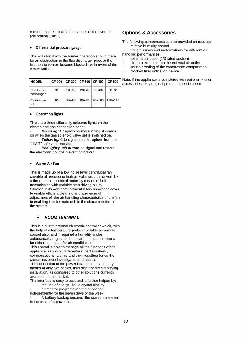
checked and eliminated the causes of the overheat (calibration 100°C).
• Differen al pressure gauge This will shut down the burner operation should there be an obstruction in the flue discharge pipe, or the inlet to the venter become blocked , or in event of the venter failing .
• Opera on lights There are three differently coloured lights on the electric and gas connection panel: · Green light, Signals normal running; it comes on when the gas solenoid valve set is switched on. · Yellow light, to signal an interruption from the “LIMIT” safety thermostat. · Red light push button, to signal and restore the electronic control in event of lockout .
• Warm Air Fan This is made up of a low noise level centrifugal fan capable of producing high air volumes , it is driven by a three phase electrical motor by means of belt transmission with variable step driving pulley. Situated in its own compartment it has an access cover to enable efficient cleaning and also ease of adjustment of the air handling characteristics of the fan to enabling it to be matched to the characteristics of the system.
• ROOM TERMINAL This is a multifunctional electronic controller which, with the help of a temperature probe (available as remote control also, and if required a humidity probe automatically regulates the environmental conditions for either heating or for air conditioning. This control is able to manage all the functions of the appliance: set-point, differentials, partialisations, compensations, alarms and their resetting (once the cause has been investigated and reset ). The connection to the power board comes about by means of only two cables, thus significantly simplifying installation, as compared to other solutions currently available on the market. The interface is easy to use, and is further helped by: · the use of a large liquid crystal display; · a timer for programming the appliance independently for the seven days of the week. · A battery backup ensures the correct time even in the case of a power cut.
Options & Accessories The following components can be provided on request: · relative humidity control · transmissions and motorizations for different air handling performances · external air outlet (1/3 rated section) · bird protection net on the external air outlet · sound-proofing of the compressor compartment · blocked filter indication device Note: if the appliance is completed with optional, kits or accessories, only original products must be used.
MODEL CF 100 CF 200 CF 300 CF 400 CF 500
Combined exchanger
30 20+30 20+40 30+60 60+60
Calibration Pa
90 85+90 85+85 90+195 195+195
11
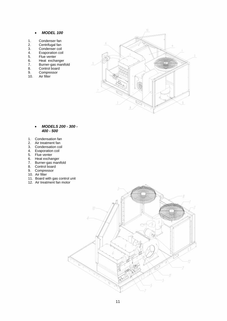
• MODEL 100 1. Condenser fan 2. Centrifugal fan 3. Condenser coil 4. Evaporation coil 5. Flue venter 6. Heat exchanger 7. Burner-gas manifold 8. Control board 9. Compressor 10. Air filter
• MODELS 200 - 300 - 400 - 500
1. Condensation fan 2. Air treatment fan 3. Condensation coil 4. Evaporation coil 5. Flue venter 6. Heat exchanger 7. Burner-gas manifold 8. Control board 9. Compressor 10. Air filter 11. Board with gas control unit 12. Air treatment fan motor

12
Installation , Commissioning and Servicing must only be carried out by suitably qualified personnel .
• GAS CONNECTION It is recommended that reference is made to the wiring diagrams contained within this manual prior to installation or connection to the supply. The electrical supply must be as specified and suitable for the unit, and must be run within conduit to a point adjacent to the unit and be terminated to provide an isolation point that will prevent remote or inadvertent activation. Cables, conduit, and fittings that are used to make the connection between the isolator and the unit must conform to the appropriate IEE regulations. Final connections for any additional external controls must be completed on site, and must be carried out according to IEE regulations. Warning Always isolate from mains electrical supply before commencing work on the appliance. Always ensure that the appropriate personal protective equipment is used.
1 Appliance male threaded union
1/2” gas CF100. 3/4” gas CF200 – CF300 – CF400 – CF500
2 Pressure stabiliser *
ensuring the correct fuel gas supply pressure • H methane gas (G20) 20 mbar • Propane gas (G31) 37 mbar 3 Filter *
For avoiding any impurities that may be present in the gas line reaching the inside of the appliance should be fitted for ease of inspection and maintenance.
4 Isolating Cock *
Should be of the 900 turn type and should be clearly marked OPEN/CLOSED it should be installed so as to fall to the closed position
5 Gas pipe * • not included customer supply .
IMPORTANT NOTICE TO INSTALLERS Installers should satisfy themselves that the gas pipework installation is carried out in accordance with all current legislation, Codes of Practice and recommendations . Additionally it may be necessary to protect the gas valves which form part of the heater or burner assembly from potential pipe contamination particularly, but not exclusively , where copper gas pipework is used. In instances where copper pipework is to be used for all or part of a gas pipework installation, including short length final connections then we advise that installers consult with gas supplier or provider and satisfy themselves what additional precautions may be necessary Notes for connection to liquid gas: For LPG supply, the installation of an initial pressure reducer near the liquid gas tank is recommended, to reduce the pressure to 1.5 bar and a second reducer near the unit to bring the pressure from 1.5 bar to 40 mbar max. A third reducer mounted near the appliance will ensure the correct supply pressure. To prevent any problems that may arise (soot or ignition failure), due to low pressure in the tank we recommend the mounting of a minimum pressure gauge.
• ELECTRICAL CONNECTION External Units are supplied fused and pre-wired, all must be earthed. The installer should carry out the following: Wire up the control complete with the room thermostat to the terminal board. Position the room thermostat in a central zone, about 1.5 m from the floor away from draughts or sources of heat or cold. Furthermore, the unit has options for the connection of the following auxiliary functions: luminous push button for control unit signalling and reset; · alarm signalling (optional); · humidifier control (optional). WARNING! INCORRECT ELECTRICAL CONNECTION CAN CAUSE SERIOUS DAMAGE TO THE CONTROL EQUIPMENT
13
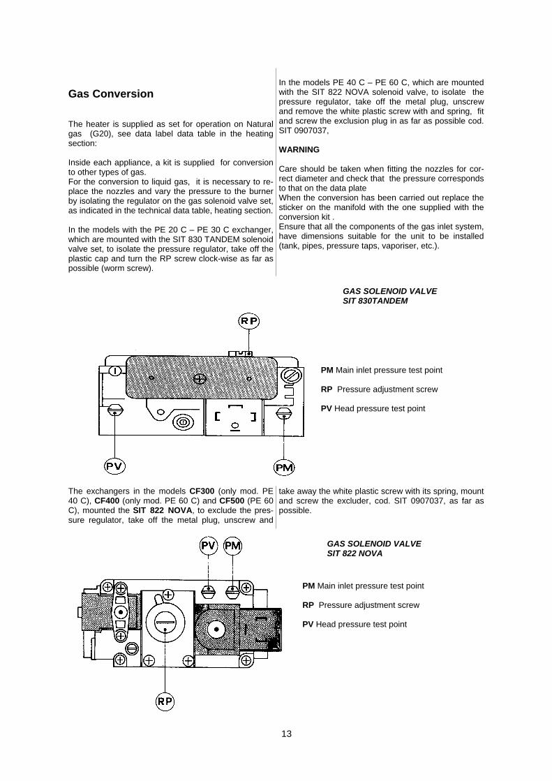
Gas Conversion The heater is supplied as set for operation on Natural gas (G20), see data label data table in the heating section: Inside each appliance, a kit is supplied for conversion to other types of gas. For the conversion to liquid gas, it is necessary to re-place the nozzles and vary the pressure to the burner by isolating the regulator on the gas solenoid valve set, as indicated in the technical data table, heating section. In the models with the PE 20 C – PE 30 C exchanger, which are mounted with the SIT 830 TANDEM solenoid valve set, to isolate the pressure regulator, take off the plastic cap and turn the RP screw clock-wise as far as possible (worm screw).
In the models PE 40 C – PE 60 C, which are mounted with the SIT 822 NOVA solenoid valve, to isolate the pressure regulator, take off the metal plug, unscrew and remove the white plastic screw with and spring, fit and screw the exclusion plug in as far as possible cod. SIT 0907037, WARNING Care should be taken when fitting the nozzles for cor-rect diameter and check that the pressure corresponds to that on the data plate When the conversion has been carried out replace the sticker on the manifold with the one supplied with the conversion kit . Ensure that all the components of the gas inlet system, have dimensions suitable for the unit to be installed (tank, pipes, pressure taps, vaporiser, etc.).
GAS SOLENOID VALVE SIT 830TANDEM
PM Main inlet pressure test point RP Pressure adjustment screw PV Head pressure test point
The exchangers in the models CF300 (only mod. PE 40 C), CF400 (only mod. PE 60 C) and CF500 (PE 60 C), mounted the SIT 822 NOVA, to exclude the pres-sure regulator, take off the metal plug, unscrew and
take away the white plastic screw with its spring, mount and screw the excluder, cod. SIT 0907037, as far as possible.
PM Main inlet pressure test point RP Pressure adjustment screw PV Head pressure test point
GAS SOLENOID VALVE SIT 822 NOVA

14
The exchanger mounted into the B-CF100 (PE 30 C) and the 2nd exchanger of the B-CF500 (PE 60 C) use a two stage SIT 843 SIGMA gas solenoid valve.
Control and adjustment of the maximum pressure (maximum heat rate): Connect a pressure gauge to the pressure take-off fitting PV to measure the injector working pressure. Set up the air heater for operation at the maximum heat rate. Check that the injector working pressure corresponds to the Number plate data. To adjust the maximum pressure and if necessary, to ex-clude adjustment: Remove the transparent plug “E” that protects the pressure regulator of the gas solenoid valve. Use a 10mm spanner to adjust the regulator nut “C”. Turning clockwise, the outlet pressure increases; Turning anticlockwise, the pressure decreases. Refit the transparent cover “E” and seal with red paint.
PM Main inlet pressure test point RP Pressure adjustment screw PV Head pressure test point
Gas Conversion WARNING Check the diameter of the nozzles are suitable for the gas supply and that the gas pressure to the burner, corresponds to the values on the label. Once the conversion has been completed, replace the adhesive label on the burner bar with the one provided in the conversion kit Ensure that all the components of the gas inlet system, have dimensions suitable for the unit to be installed (tank, pipes, pressure taps, etc.). To operate or shutdown the appliance, only the ROOM TERMINAL, which comes with the appliance and is positioned inside the building must be used Installation, commissioning, and servicing must only be carried out by appropriately qualified and competent persons. When installation is complete and before initial start up, it is essential to: ·Ensure the fan operates in the correct rotation and adjust the air delivery , if necessary, to the rated value. The appliances are all designed with the transmission ratio regulated in such a way that the rated air delivery may be obtained in the majority of installation cases. It is however necessary to check that the motor absorption does not go beyond that set on the label, the fan revs can be varied to achieve this result. To check the motor’s electrical absorption, proceed as follows: Insert the ampere-hour meter onto one of the phases of the mains supply line. Set the appliance to function in summer ventilation (FAN), so it excludes any other equipment. Read the absorption value on the ampere-hour meter and compare it with the data on the label of the motor itself.
CF 100 CF 200 CF 300 CF 400 CF 500
W 750 1500 2200 2200 3000
A 2.0 3.6 5.1 5.1 6.5
Slacken belt by unscrewing screw 2 Remove belt 1 Using an allen key 5 slacken grub screws 4 on the pulley 3 Turn pulley until required pitch diameter is reached Lock grub screws 4 on the shaft Replace belts and tighten Caution do not over tighten the belt , deflection should be approximately 20 / 30 mm
15
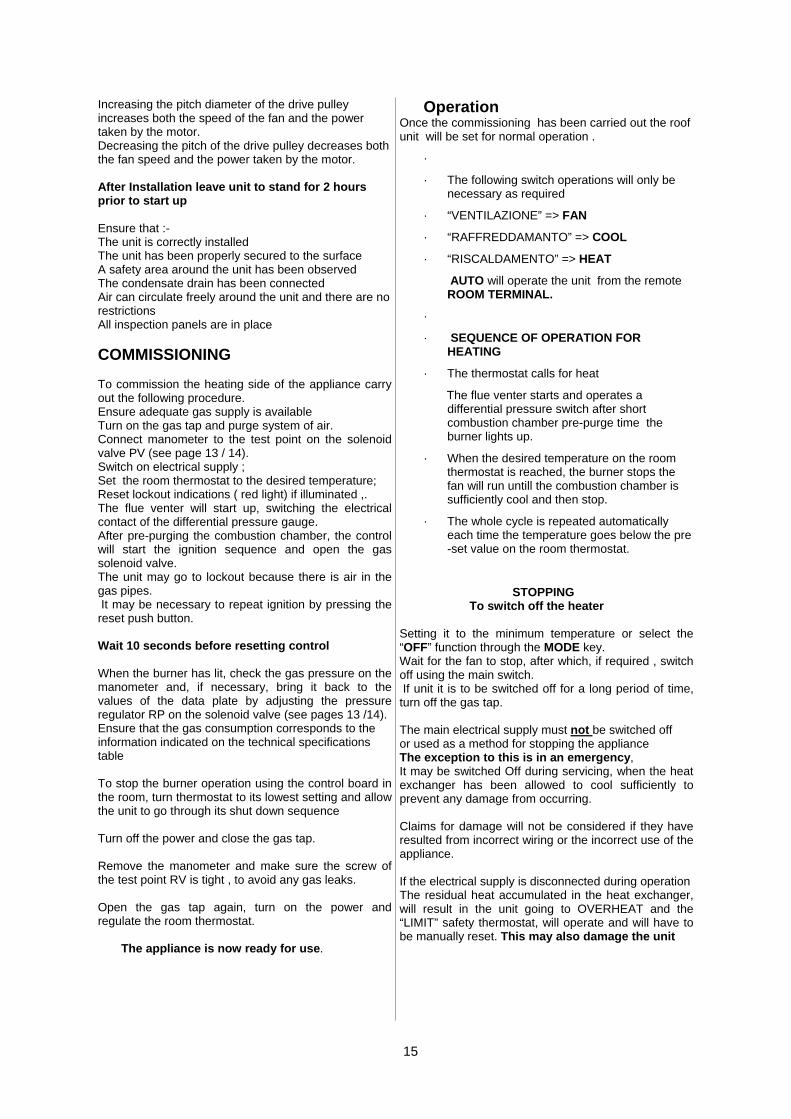
Increasing the pitch diameter of the drive pulley increases both the speed of the fan and the power taken by the motor. Decreasing the pitch of the drive pulley decreases both the fan speed and the power taken by the motor. After Installation leave unit to stand for 2 hours prior to start up Ensure that :- The unit is correctly installed The unit has been properly secured to the surface A safety area around the unit has been observed The condensate drain has been connected Air can circulate freely around the unit and there are no restrictions All inspection panels are in place COMMISSIONING To commission the heating side of the appliance carry out the following procedure. Ensure adequate gas supply is available Turn on the gas tap and purge system of air. Connect manometer to the test point on the solenoid valve PV (see page 13 / 14). Switch on electrical supply ; Set the room thermostat to the desired temperature; Reset lockout indications ( red light) if illuminated ,. The flue venter will start up, switching the electrical contact of the differential pressure gauge. After pre-purging the combustion chamber, the control will start the ignition sequence and open the gas solenoid valve. The unit may go to lockout because there is air in the gas pipes. It may be necessary to repeat ignition by pressing the reset push button. Wait 10 seconds before resetting control When the burner has lit, check the gas pressure on the manometer and, if necessary, bring it back to the values of the data plate by adjusting the pressure regulator RP on the solenoid valve (see pages 13 /14). Ensure that the gas consumption corresponds to the information indicated on the technical specifications table To stop the burner operation using the control board in the room, turn thermostat to its lowest setting and allow the unit to go through its shut down sequence Turn off the power and close the gas tap. Remove the manometer and make sure the screw of the test point RV is tight , to avoid any gas leaks. Open the gas tap again, turn on the power and regulate the room thermostat. The appliance is now ready for use.
Operation Once the commissioning has been carried out the roof unit will be set for normal operation .
·
· The following switch operations will only be necessary as required
· “VENTILAZIONE” => FAN
· “RAFFREDDAMANTO” => COOL
· “RISCALDAMENTO” => HEAT
AUTO will operate the unit from the remote ROOM TERMINAL.
·
· SEQUENCE OF OPERATION FOR HEATING
· The thermostat calls for heat
The flue venter starts and operates a differential pressure switch after short combustion chamber pre-purge time the burner lights up.
· When the desired temperature on the room thermostat is reached, the burner stops the fan will run untill the combustion chamber is sufficiently cool and then stop.
· The whole cycle is repeated automatically each time the temperature goes below the pre-set value on the room thermostat.
STOPPING To switch off the heater Setting it to the minimum temperature or select the “OFF” function through the MODE key. Wait for the fan to stop, after which, if required , switch off using the main switch. If unit it is to be switched off for a long period of time, turn off the gas tap. The main electrical supply must not be switched off or used as a method for stopping the appliance The exception to this is in an emergency, It may be switched Off during servicing, when the heat exchanger has been allowed to cool sufficiently to prevent any damage from occurring. Claims for damage will not be considered if they have resulted from incorrect wiring or the incorrect use of the appliance. If the electrical supply is disconnected during operation The residual heat accumulated in the heat exchanger, will result in the unit going to OVERHEAT and the “LIMIT” safety thermostat, will operate and will have to be manually reset. This may also damage the unit

16
DESCRIPTION B-CF GAS MODEL
100 200 300 400 500
Total cooling capacity (1) kW 23.8 35.5 47.6 64.5 92.2
Partial cooling capacity (1) kW 17.7 23.8 32.2 46.1
Sensible cooling capacity (1) kW 15.9 23.8 31.9 43.2 61.7
Power absorbed by compressor (1) kW 5.6 8.5 11.2 15.6 22.1
Heating range kW 33.8 59.2 71.7 98.8 130.0
Thermal efficiency % 90.2 90.4 90.2 90.2 90.2
Heating capacity kW 30.5 53.5 64.7 89.1 117.2
Medium heating capacity kW 30.5 41.7 58.6 58.6
Minimum heating capacity kW 21.1 23.0 23.0 30.5 40.5
Category 112H3+
Air delivery m3/h 3500 5800 7400 9700 12600
Static working pressure (STD) Pa 250 250 250 250 250
Fan motor kW 0.75 1.5 2.2 2.2 3.0
Heat exchanger type RSUH 105 80 + 105 80 + 140 105 + 200 200 + 200
Natural Gas G20 ( 20 m/bar) No of nozzles Head pressure Gas consumption (2)
mm/100 N
m/bar N m3/h
280 3
13 (7) 3.39
255 + 280 3 + 3
11 + 13 5.37
255 + 340 3 + 3
11 + 11 7.2
280 + 330 3 + 4
13 + 12.5 9.91
330 + 330 4 + 4
12.5 + 12.5 13.05
Propane Gas G31 ( 37m/bar) No of nozzles Head pressure Gas consumption (2)
Mm / 100 N
m/bar kg/h
170 3
35.9(19) 2.63
150 + 170 3 + 3
29.2+29 4.22
150 + 200 3 + 3
29.2+28.8 5.65
170 + 200 3 + 4
29 + 28 7.79
200 + 200 4 + 4
28+28(17) 10.25
Electrical supply
Operating temperatures -20 / +45
Electrical protection IP54
Sound level @ 6M Db(A) 51.0 43.8 54.0 46.5 54.4
QUANTITY- R407C GAS Kg 2.6 2 X 2.4 2 X 2.9 2 X 4.5 2 X 5.8
Weight Kg 570 770 890 980 1140
400 / 3N / 50
(1) Refers to entering treated air 26,7°C b.s. – 19,4° b.u., external air 35°C. (2) The data refers to gas in the following environmental conditions : 15°C; 1013 mbar.
Model Voltage supply V/50Hz
(1) Max power absorbed in
cooling kW
(1) Max current absorbed
A
(2) Main switch A
(3) Line con-ductor section
mm2
(3) Earth con-ductor section
mm2
B-CF 100 400V 3N∼ 9.38 19.5 25 4 4
B-CF 200 400V 3N∼ 13.88 26.3 32 6 6
B-CF 300 400V 3N∼ 19.46 40.1 50 6 6
B-CF 400 400V 3N∼ 25.76 44.6 63 10 10
B-CF 500 400V 3N∼ 35.36 60.4 80 16 16
(1) Refers to entering treated air 26,7°C b.s. – 19,4° b.u., external air 45°C. (2) Included in the machine supply. (3) The section of the power supply lead ensures drop below 5% for a length of 30 metres.

17
Wiring diagram (HEATING SECTION)
Legend PD Differential pressure gauge PSL Light push button for appliance reset EA Ignition Electrode EI Flame detecting Electrode FA Fan thermostat LM LIMIT thermostat TR Regulation thermostat
LF Indication running light LL LIMIT intervention signaller EF Flue venter EV1 Gas solenoid valve TEST Safety test bridge AP Electronic equipment MD 2nd stage solenoid valve (only B-CF 100 and 500)

18
B-CF 100 Control box terminal board
Q Main switch + block TABASE5000 Microprocessor board
S1 Supply phases rotation direction relay ARIA Room terminal
C1 Compressor A1 High pressure gauge
M1 Fan motor B1 Low pressure gauge
V1 Condensation fan PSL Reset switch
CV Break condenser L Lockout indication light
F1 Compressor protection fuses LL LIMIT indication light
F3 Electric fan protection fuse LF Operating light
F4 Auxiliary protection fuse K1 Compressor contactor
F5 Board protection fuse K2 Delivery fan motor contactor
T1 Delivery fan motor thermal switch K3 Electric fan contactor
TRA Transformer TM Minimum fan thermostat
SR1 Heating section MD 2nd stage solenoid valve
SV Fan derivation box

19
MODELS 200 - 300 - 400 - 500 Control box terminal board
Q Main switch + block A1 Circuit 1 high pressure gauge
S1 Phase cyclic direction detector B1 Circuit 1 low pressure gauge
T1 Delivery fan motor thermal switch A2 Circuit 2 high pressure gauge
C1 Circuit 1 compressor B2 Circuit 2 low pressure gauge
C2 Circuit 2 compressor SR1 Heating section 1
M1 Fan delivery motor SR2 Heating section 2
V1 Circuit 1 condensation electric fan PSL1 Circuit 1 reset switch (illuminated)
V2 Circuit 1 condensation electric fan PSL2 Circuit 2 reset switch (illuminated)
F1 Compressor 1 protection fuses L Lockout indication light
F2 Compressor 2 protection fuses LL LIMIT intervention light
F4 Electric fan protection fuse LF Running light
F5 Auxiliary protection fuse TM Minimum fan thermostat
F6 Board protection fuse R1 SR1 auxiliary relay (only CF200-300-400)
K1 Compressor 1 contactor R2 SR2 auxiliary relay (only CF200-300-400)
K2 Compressor 2 contactor MD 2nd stage solenoid valve (only CF 100 and 500)
K3 Delivery fan motor contactor PC1 Compressor 1 protection (only CF 24-35-36)
K4 Circuit 1 electric fan contactor PC2 Compressor 2 protection (only CF 24-35-36)
K5 Circuit 2 electric fan contactor CV1 Fan condenser 1 (only on CF 23-24)
TRA Transformer CV2 Fan condenser 2 (only on CF 23-24)
ARIA Room terminal SV Fan derivation box
Power section Condens. fan section CF200-300
Condens. fan section CF400-500

20
Control section CF 200-300-400
Control section 500
21
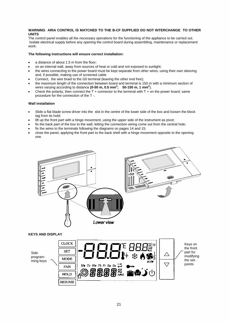
WARNING ARIA CONTROL IS MATCHED TO THE B-CF SUPPLIED DO NOT INTERCHANGE TO OTHER UNITS The control panel enables all the necessary operations for the functioning of the appliance to be carried out. Isolate electrical supply before any opening the control board during assembling, maintenance or replacement work. The following instructions will ensure correct installation: • a distance of about 1.5 m from the floor; • on an internal wall, away from sources of heat or cold and not exposed to sunlight; • the wires connecting to the power board must be kept separate from other wires, using their own sleeving
and, if possible, making use of screened cable • Connect, the wire braid to the G0 terminal (leaving the other end free); • the maximum length of the connection between board and terminal is 150 m with a minimum section of
wires varying according to distance (0-50 m, 0.5 mm2; 50-150 m, 1 mm2); • Check the polarity, then connect the T + connector to the terminal with T + on the power board; same
procedure for the connection of the T -. Wall installation • Slide a flat blade screw driver into the slot in the centre of the lower side of the box and loosen the block
tag from its hold; • lift up the front part with a hinge movement, using the upper side of the instrument as pivot; • fix the back part of the box to the wall, letting the connection wiring come out from the central hole; • fix the wires to the terminals following the diagrams on pages 14 and 15; • close the panel, applying the front part to the back shell with a hinge movement opposite to the opening
one.
Keys on the front part for modifying the set-points
Side program-ming keys
KEYS AND DISPLAY

22
MODE (FUNCTIONING SELECTION) This enables the setting of the running mode of the appliance: • OFF: the thermostat does not effect regulation: it prevents the temperature from passing below the low
safety limit; • COOL: the thermostat controls cooling only; • HEAT: the thermostat controls heating only; • AUTO: (automatic) control of cooling and heating. The system passes automatically from one function to
the other, on the basis of the environmental temperature and the set-point; • FAN: fan only. On pressing the key in the function time period mode, you have the visualisation for 5 seconds of the current function mode (indicated by the corresponding writing flashing in place of the clock). In the manual function mode instead, the function mode is always indicated. By continuously pressing, you can alternate the function modes possible for the selected model of machine.
• SET (SETTING THE TEMPERATURE AND HUMIDITY SET-POINTS) It is possible to set three different categories of temperature set-points, indicated with appropriate symbols, as well as the limit category for machine off: • Comfort : There are people in the room and so a certain level of comfort is required; • Nightime : The room is occupied but a lower level of comfort is required, obtainable by adjusting the
intervention of cooling and heating as compared with the comfort set-point; Room not in constant use : This mode can be selected when there are no people in the room. The variation of temperature which is accepted as compared with the comfort set-point is even greater than the nightime function, given that heating and cooling occur with temperature values which are even further from the set-points. By pressing the SET key in manual mode (HOLD), the set-point category used can be changed for regulation. In a timer function, instead, it is set automatically by the programme, previously memorised. If you press [^] or [v] within 5 seconds of pressing SET (the relative symbols flash), the values of the selected mode can be modified. The temperature values for the various set modes are the following: Holding down the SET key for three seconds, you can modify the setting of the humidity set-point. The modification is effectively recognised after 5 seconds. Example of setting a SET-POINT: Let’s consider you wish to set the following temperature values for the various modes:
:
Categories Set (°C)
21
± 2
± 4
Categories Temperature C)
21
± 2
± 4

23
Pressing the SET key you will see the writing HEAT come up on the display, bottom left, and at the same time the symbol flashes With the [^] and [v ] keys, within 5 seconds of pressing the SET key, set the SET-POINT value to 22°C (shown top right on display). Pressing the SET key again, the symbol bottom right, flashes. With the [^] and [v] keys, set the value of the SET-POINT displayed at the top on the right, to 5°C (22°C-5°C=17°C). Pressing the SET key again, the symbol at the bottom, on the right, flashes. With the [^] and [v] set the value of the SET-POINT, displayed at the top, on the right, to 8°C (22°C-8°C=14°C). Pressing the RESUME key or after 5 seconds of no activity, you return to normal mode and the modifications set are memorised. Clock (clock and time periods) Programming the clock: By repeatedly pressing the CLOCK key, the value (day, hour, minute) to be set is selected. It can be modified with [^] and [v] and pressing again confirms it. Pressing RESUME or after 60 seconds of no activity, you return to normal mode, losing the modifications made. Time periods: The time periods are time intervals where a 24-hour day is subdivided, and in each time period you can decide the function mode of the unit, choosing from the different options:
It is possible to have 6 different time periods for
each of the 7 days of the week. When programming, the time periods are indicated
on the small top right-hand display as follows: t1-t2-t3-t4-t5-t6. If you select one of the comfort, nightime, absence symbols for a time period, the unit functions respecting the value of the set temperature, for the space of time in question.
If you select the symbol Stand by for a time period, the unit is switched off during the interval of time in question. Then if you have selected one of the set-point symbols (comfort, nightime, away) in the subsequent time period, the unit automatically switches itself back on again. When a Stand by time period has been activated, if the unit has not already been switched off by the Mode key, the Stand by symbol flashes.
Setting the time periods: To set a programme, after having pressed the CLOCK key for more than three seconds, you must proceed as follows: set the programming day; set the hour and minutes of the start of the first time period; set the temperature required for that period;
at the end of programming the time period the continue symbol (O) and end (+) symbols light up, together with the words: CONT and END; with continue, you move cyclically to the following time periods, setting the hours and minutes for the start of the second time period and so on (the current time period ends when the one after begins); with end, you terminate the programming for that day (reducing if necessary, the number of time periods if you do not wish to use them all). after end or after having programmed the last time period for the current day, the programmed day of the week flashes on and then the word COPY. With [^] and [v] the other days are added on to each other, with lights flashing and with the CLOCK key you confirm, thus extending the programming to the other days selected too. The continue (flashing) and end symbols come on and the corresponding words CONT and MEMO; with memo, you come out of the programming mode and activate the time period function. If there are some days left out from setting, these will keep the previous programme. If instead you press RESUME, or after 1 minute of no activity, all modifications carried out are lost; with continue, you pick up the programming of the remaining days. The time interval identified by the current time period is visualised on the display with the symbol of a segmented clock having a resolution of 1 hour For example, the time period from 3 to 7 is indicated like this: . The time periods only refer to the temperature control and not to the humidity one which always functions on the same set-point.
• HOLD This permits you to exit from any phase of the programming whatsoever, whilst saving the modifications done. It carries out the passage from time period function to manual function; the word HOLD lights up and the comfort set-point is restored, no matter what the previous function set-point was.
• RESUME This enables you to exit the programme you are running without saving any of the modifications; It takes you out of the manual function (HOLD) and goes back to the time period management. By pressing it for more than three seconds, it restores all alarms present, with the deactivation of the display message and alarm relay, if the alarm conditions have effectively ceased.
• FAN This selects the functioning logic of the fan: turned on in continuous mode; the delivery fan follows the functioning of the actuators
.
24
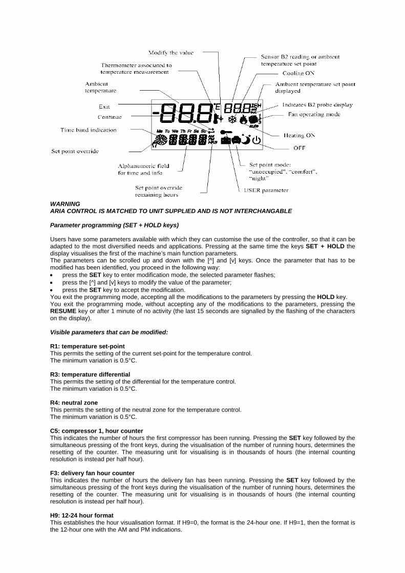
WARNING ARIA CONTROL IS MATCHED TO UNIT SUPPLIED AND IS NOT INTERCHANGABLE Parameter programming (SET + HOLD keys) Users have some parameters available with which they can customise the use of the controller, so that it can be adapted to the most diversified needs and applications. Pressing at the same time the keys SET + HOLD the display visualises the first of the machine’s main function parameters. The parameters can be scrolled up and down with the [^] and [v] keys. Once the parameter that has to be modified has been identified, you proceed in the following way: • press the SET key to enter modification mode, the selected parameter flashes; • press the [^] and [v] keys to modify the value of the parameter; • press the SET key to accept the modification. You exit the programming mode, accepting all the modifications to the parameters by pressing the HOLD key. You exit the programming mode, without accepting any of the modifications to the parameters, pressing the RESUME key or after 1 minute of no activity (the last 15 seconds are signalled by the flashing of the characters on the display). Visible parameters that can be modified: R1: temperature set-point This permits the setting of the current set-point for the temperature control. The minimum variation is 0.5°C. R3: temperature differential This permits the setting of the differential for the temperature control. The minimum variation is 0.5°C. R4: neutral zone This permits the setting of the neutral zone for the temperature control. The minimum variation is 0.5°C. C5: compressor 1, hour counter This indicates the number of hours the first compressor has been running. Pressing the SET key followed by the simultaneous pressing of the front keys, during the visualisation of the number of running hours, determines the resetting of the counter. The measuring unit for visualising is in thousands of hours (the internal counting resolution is instead per half hour). F3: delivery fan hour counter This indicates the number of hours the delivery fan has been running. Pressing the SET key followed by the simultaneous pressing of the front keys during the visualisation of the number of running hours, determines the resetting of the counter. The measuring unit for visualising is in thousands of hours (the internal counting resolution is instead per half hour). H9: 12-24 hour format This establishes the hour visualisation format. If H9=0, the format is the 24-hour one. If H9=1, then the format is the 12-hour one with the AM and PM indications.

25
• Servicing must be carried out on a regular basis, the maximum interval between services being 1 year Some appliances may require more frequent servicing only manufacturers recommended spare parts may be used .
• It is a requirement that only suitably qualified and competent persons are allowed to undertake servicing.
• Before any maintenance or servicing work is carried out the heater must be shut down and allowed to cool, and have the gas and electric supplies to it turned off at the gas cock and isolator respectively.
• External panels should be cleaned with a damp, soapy cloth.
• Difficult stains, can be removed with various cleaning products available on the market
• Dry all surfaces carefully.
• Do not use abrasive products or powder detergents.
•
• Always Isolate appliance before cleaning .
•
• WARNING
• For appliances installed near the sea, it is recommended the intervals between maintenance be halved.
•
• COMBUSTION ANALYSIS Undertake flue gas analysis using approved and calibrated analysing equipment record data ie, CO, CO2, net and gross flue temperatures. . Place the analyser sensor at the end of the flue terminal. Analysis is done with the burner compartment flap completely closed.
• CLEANING OF THE HEAT EXCHANGER As follows: · Remove the burner from its compartment; · lift the upper panel of the appliance, remove the inspection flap on the flue section and remove internal components; · clean all the exchange elements with a steel brush; · Vacuum away any possible soot from the combustion chamber, which may have fallen from the exchange elements; · clean the external surfaces of the exchanger too; · replace, the seals of the inspection flap to ensure a good seal.
• BURNER PIPE CLEANING Remove any scaling there may be with a brass brush, use carefully so as to avoid damaging the pipes, and with an air line clear the any deposits from the slots. Any bent or damaged pipes must be replaced.
• EXAUST OUTLET AND AIR INLET Remove any obstructions and/or deposits that may have formed inside.
• CONTROL AND SAFETY EQUIPMENT Check efficiency and ensure correct operation .
• CENTRIFUGAL FAN Check the tension of the belt using the special stretcher and periodically replace filters.
• FLUE VENTER Ensure fan blades are kept clean
• GAS SUPPLY Ensure all pipes and joints are correctly sealed and the solenoid vale is set at the correct pressure .
• ASSISTANCE Assembling, starting up and maintenance of the appliance, must be carried out by qualified technical personnel.
• FAILURES Should there be a failure and/or appliance malfunction, do not attempt to repair; unplug from the mains and seek help from qualified personnel.
• GAS LEAKS IF A GAS LEAK IS SUSPECTED Isolate all electrical supply immediately Isolate gas supply . Contact service engineer Open doors and windows to air the room,
Maintenance

26
Alarm code Type of alarm Meaning Reset
Th F ID1 inlet alarm Delivery fan motor thermal switch. Phase rotation detector (two-phase inverter).
Manual
LO P ID2 inlet alarm Interruption from low pressure gauge Twice. Auto / Man
E ID ID3 inlet alarm Interruption from high pressure gauge, condensation fan thermal switch.
Manual
EE EPROM error The internal memory may have lost data. Take off and plug in again.
Manual
E SR Terminal error Terminal not receiving data from board. Automatic
E ST Output board error Output board not receiving data from terminal.
Automatic
E1 B1 probe error Temperature probe failure signal. Automatic
E2 B2 probe error Humidity probe failure signal. Automatic
Should the appliance have a operational failure the letters “AL” appear on the command panel display, together with an alarm code.
ALARMS, TROUBLESHOOTING AND FAULT FINDING
The detecting of an alarm also entails: · Activation of alarm buzzer · Blocking of outlets; · Activation of alarm relay To stop the buzzer ringing press the RESUME key. The manual resetting to restore alarms – if the causes have ceased – is obtained by pressing the RESUME key for more than three seconds.

27
The appliance does not start up. Electronic board connected incorrectly.
Check the wiring.
The appliance does not start up, “TH F” appears on display.
Interruption of power supply phase rotation direction detector..
Invert two of the phases .
The compressor does not start up.
Contactor coil failure. Internal fan motor contactor failure. Electronic board failure. Compressor failure. Compressor thermal overload protection activated .
Replace the component and/or remove the cause.
The compressor stops because of intervention from protection with “E ID” appearing on display.
Excessive delivery pressure Low voltage supply Poor Electrical connection Inlet air excessively hot Thermal protection interruption
Check the cause
The compressor stops because of intervention from protection with “LO P” appearing on display
Low pump pressure
Check the cause, look for refrigerating liquid leak
Insufficient performance
Poor air delivery Incorrect thermostat calibration Incorrect sizing of appliance
Check
Noisy compressor Liquid returning to compressor Fixing incorrect
Check
Noises and vibrations
Loose screws Weak foundations Contact with other objects
Tighten screws Restore Check
Outlet pressure high
High air temperature to condenser Excessive refrigerating liquid load High temperature outlet air (low delivery) Insufficient air to condenser Uncondensable air or gas in the freon circuit
Check Check fans Bleed
Outlet pressure low
Low temperature of condensation air Faulty fan operation Compressor outlet valves leak
Check Replace
High gas pressure High intake air temperature Thermostatic expansion valve failure or open
Check
Low gas pressure
Low humidity and/or intake air temperature Thermostatic expansion valve failure or obstructed Aspiration line blocked Clogged filter Clogged evaporator exchanger
Check
FAULT CAUSE SOLUTION
Should there be any fault , first of all check that: • The electricity supply; • There are not more than + 10%, - 15% voltage sudden changes; • There is gas supply (fuel); • There is sufficient gas pressure and gas delivery correspond to the values indicated in the technical
specifications. · FOR SUMMER OPERATION
FAULT FINDING
28
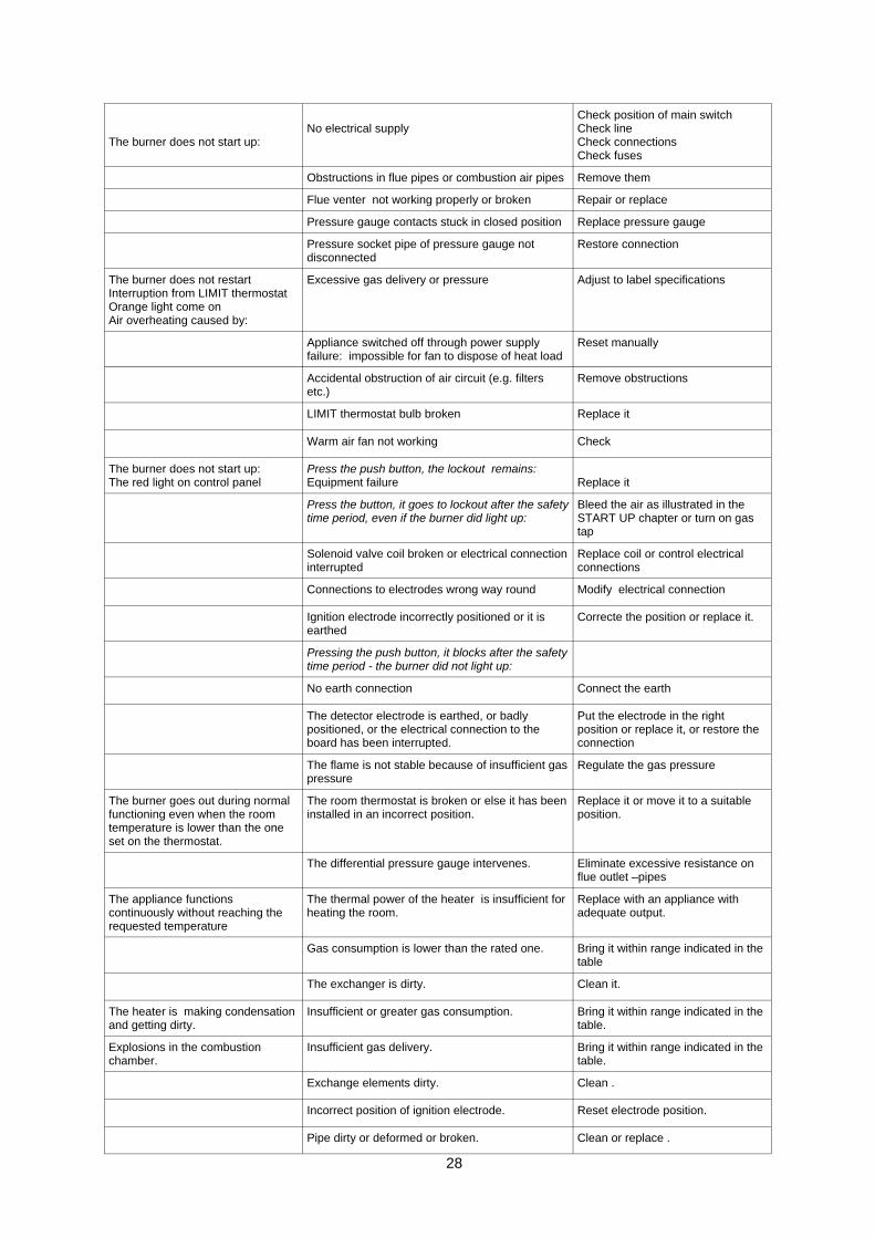
The burner does not start up:
No electrical supply
Check position of main switch Check line Check connections Check fuses
Obstructions in flue pipes or combustion air pipes Remove them
Flue venter not working properly or broken Repair or replace
Pressure gauge contacts stuck in closed position Replace pressure gauge
Pressure socket pipe of pressure gauge not disconnected
Restore connection
The burner does not restart Interruption from LIMIT thermostat Orange light come on Air overheating caused by:
Excessive gas delivery or pressure Adjust to label specifications
Appliance switched off through power supply failure: impossible for fan to dispose of heat load
Reset manually
Accidental obstruction of air circuit (e.g. filters etc.)
Remove obstructions
LIMIT thermostat bulb broken Replace it
Warm air fan not working Check
The burner does not start up: The red light on control panel
Press the push button, the lockout remains: Equipment failure
Replace it
Press the button, it goes to lockout after the safety time period, even if the burner did light up:
Bleed the air as illustrated in the START UP chapter or turn on gas tap
Solenoid valve coil broken or electrical connection interrupted
Replace coil or control electrical connections
Connections to electrodes wrong way round Modify electrical connection
Ignition electrode incorrectly positioned or it is earthed
Correcte the position or replace it.
Pressing the push button, it blocks after the safety time period - the burner did not light up:
No earth connection Connect the earth
The detector electrode is earthed, or badly positioned, or the electrical connection to the board has been interrupted.
Put the electrode in the right position or replace it, or restore the connection
The flame is not stable because of insufficient gas pressure
Regulate the gas pressure
The burner goes out during normal functioning even when the room temperature is lower than the one set on the thermostat.
The room thermostat is broken or else it has been installed in an incorrect position.
Replace it or move it to a suitable position.
The differential pressure gauge intervenes. Eliminate excessive resistance on flue outlet –pipes
The appliance functions continuously without reaching the requested temperature
The thermal power of the heater is insufficient for heating the room.
Replace with an appliance with adequate output.
Gas consumption is lower than the rated one. Bring it within range indicated in the table
The exchanger is dirty. Clean it.
The heater is making condensation and getting dirty.
Insufficient or greater gas consumption. Bring it within range indicated in the table.
Explosions in the combustion chamber.
Insufficient gas delivery. Bring it within range indicated in the table.
Exchange elements dirty. Clean .
Incorrect position of ignition electrode. Reset electrode position.
Pipe dirty or deformed or broken. Clean or replace .

29
BENSON HEATING LUDLOW ROAD KNIGHTON POWYS LD7 1LP Telephone +44 (0) 1547 528534 Facsimile +44 (0) 1547 520399 email [email protected] Web www.bensonheating.com Benson Heating is a division of BENSON CLIMATE SYSTEMS LTD