technical service guideapplianceservicesecretsmembership.com_manuals.s3...g ge consumer service...
TRANSCRIPT

gGE Consumer Service Training
TECHNICAL SERVICE GUIDE1999 SPECTRA™ SERIES - FREE-STANDING
ELECTRIC RANGES W/ TRUETEMPTM
g03/99
MODEL SERIES:JB960_BJB940_BJBP79_BJBP78_BJBP63_BJBP64_BJBP66_BJBP60_BJBP48_BJBP35_BJBP30_BJBP26_BJBP24_BJBP21_BJBP19_B

CAUTION To avoid personal injury while servicing this unit, disconnect power before servicing. If grounding wires, screws, straps, clips, nuts, or washers used to complete a path to ground are removed for service, they must be returned to their original position and properly fastened.
IMPORTANT SAFETY NOTICE The information in this service guide is intended for use by individuals possessing adequate backgrounds of electrical, electronic and mechanical experience. Any attempt to repair a major appliance may result in personal injury and property damage. The manufacturer or seller cannot be responsible for the interpretation of this information, nor can it assume any liability in connection with its use.
– 1 –
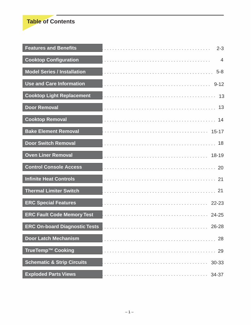
34-37
21
22-23
24-25
26-28
28
29
30-33
Features and Benefits
Cooktop Configuration
Model Series / Installation
Use and Care Information
Cooktop Light Replacement
Door Removal
Cooktop Removal
Bake Element Removal
Door Switch Removal
Oven Liner Removal
Control Console Access
Infinite Heat Controls
Thermal Limiter Switch
ERC Special Features
ERC Fault Code Memory Test
ERC On-board Diagnostic Tests
Door Latch Mechanism
TrueTemp™ Cooking
Schematic & Strip Circuits
Exploded Parts Views
2-3
4
5-8
9-12
13
13
Table of Contents
14
15-17
18
18-19
20
21
– 2 –
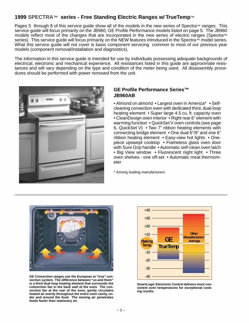
1999 SPECTRA™ series - Free Standing Electric Ranges w/ TrueTemp ™
Pages 5 through 8 of this service guide show all of the models in the new series of Spectra™ ranges. Thisservice guide will focus primarily on the JB960, GE Profile Performance models listed on page 5. The JB960models reflect most of the changes that are incorporated in the new series of electric ranges (Spectra™series). This service guide will focus primarily on the NEW features introduced in the Spectra™ model series.What this service guide will not cover is basic component servicing common to most of our previous yearmodels (component removal/installation and diagnostics).
The information in this service guide is intended for use by individuals possessing adequate backgrounds ofelectrical, electronic and mechanical experience. All resistances listed in this guide are approximate resis-tances and will vary depending on the type and condition of the meter being used. All disassembly proce-dures should be performed with power removed from the unit.
GE Profile Performance Series™JB960AB
• Almond on almond • Largest oven in America* • Self-cleaning convection oven with dedicated third, dual-loopheating element • Super large 4.5 cu. ft. capacity oven• CleanDesign oven interior • Right rear 6” element withwarming function • QuickSet V oven controls (see page6, QuickSet V) • Two 7” ribbon heating elements withconnecting bridge element • One dual 6”/9” and one 6”ribbon heating element • Easy-view hot lights • One-piece upswept cooktop • Frameless glass oven doorwith Sure Grip handle • Automatic self-clean oven latch• Big View window • Fluorescent night light • Threeoven shelves - one off-set • Automatic meat thermom-eter
* Among leading manufacturers
GETrueTemp
+40
+30
+20
+10
BakingTemp.
-10
-20
-30
-40
Other Manufacturers'
Average
GE Convection ranges use the European or “true” con-vection system. The difference between “us and them”is a third dual loop heating element that surrounds theconvection fan in the back wall of the oven. The con-vection fan at the rear of the oven, gently circulatesheated air evenly throughout the entire oven cavity, un-der and around the food. The moving air penetratesfoods faster than stationary air.
SmartLogic Electronic Control delivers more con-sistent oven temperatures for exceptional cook-ing results.

– 3 –
➊
➋
➌
➍
➎ ➏
➐
➑ ➒
➓
Ten exclusives make it super versatile,super accurate and easy-to-clean
1.1.1.1.1. Seamless backguard Design 5.5.5.5.5. 5.0 cu. ft. oven capacity 9.9.9.9.9. CleanDesign Interior2.2.2.2.2. Bridge element 6.6.6.6.6. Largest usable capacity 10.10.10.10.10. Largest broiler pan3.3.3.3.3. Frameless glass oven door 7.7.7.7.7. Six rack design4.4.4.4.4. TrueTemp™ 8.8.8.8.8. Six-Pass bake element
With the largest, most accurate oven in america and a variety of cooktop elements, theGE Spectra™ Range lets you cook exactly what you want to cook. And with CleanDesign,cleanup has never been easier or faster!
Exclusive CleanDesignAs for cleanability, the CleanDesign oven interior* con-ceals the lower oven element under a porcelain-coatedsteel surface. All you see and clean is a flat, smooth ovensurface.
* on select models
Convenient New Warming OptionKeeps soups, sauces, breads and pancakes warm, ormelts butter and chocolate. Or use this new burner asyou would any other element.

– 4 –
OFF
FRONTREAR
HOTCOOKTOP
LARGEBURNERSMALL
BURNEROFF
OFF
FRONT REARProfile Performance
HOTCOOKTOP
BRIDGEBURNERFRONT
BURNER
OFFTrueTemp
Convection
1CLEAROFF
PROBE
SELFCLEAN
COOKINGTIME
KITCHENTIMER
OVENLIGHT
DELAYSTART
CLOCK
TOPLIGHT
BAKE
BAKECONVECTION
ON OFF ROASTCONVECTION
BROIL
START
2 3 4 5 6 7 8 9 0
OVENTIME CONTROLS
H S
2
DUALELEMENT
1000 W
2500 W
H S
4
2
SINGLEELEMENT
1500 W
WM
REAR
HI88
HI
6
64
2
LOLO 2
4
SMALLBURNER
LARGEBURNER
OFF
WM
FRONT
BRIDGE SURFACEELEMENT ASSY.
1800 W
1800 W
LR
LF
BRIDGE
2600 W
RR
RFSMALL
RFLARGE
(Inner & Outer)
RF SMALL 1000 W
RF LARGE 2500 W(BOTH ELEMENTS)
RR 1500 W
LF SINGLE 1800 W
LF BRIDGE 2600 W(LF + CENTER)
LR 1800 W
LOCATION WATTAGE
CO
OK
TOP
CO
NF
IGU
RAT
ION
HI88
HI
664
2LO LO 2
4
BRIDGEBURNER
OFF
FRONTBURNER
FRONT REAR
TrueTemp
Convection
OVEN
BAKEPROBE
SELFCLEAN
CLEAROFF
BAKE
1 2 3 4 5 6 7 8
CONVECTIONROAST
CONVECTION
BROIL
CLOCK
START
HI LO
KITCHENTIMER OVEN
LIGHT
TOPLIGHT
COOKINGTIME
DELAYSTART
TIME CONTROLS
ON OFF
9 0CONTROL LOCKOUT
= LF Element Only
= LF Element + Center Bridge Element
= RF Inner & Outer Element
= RF Inner Element Only
H1
P
H2
L2L1
CURRENTSENSITIVECONTROL
5 N
2 3
L1 H1
TOP
4P
L2
H2
GRND
VOLTAGESENSITIVECONTROL (DUAL)
5 N
2 3
L1 H1
TOP
4P
L2
H2
GRND
VOLTAGESENSITIVECONTROL (DUAL)
VOLTAGESENSITIVECONTROL
H1
P
H2
L1 L2
TOP
ERC V (QUICKSET V) - WITH CAPACITANCE TOUCH CONTROLS
– 5 –
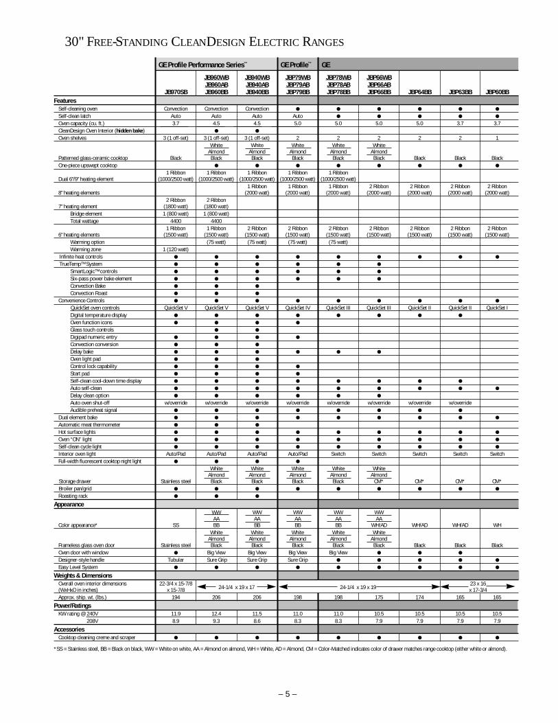
JB960WB JB940WB JBP79WB JBP78WB JBP66WBJB960AB JB940AB JBP79AB JBP78AB JBP66AB
JB970SB JB960BB JB940BB JBP79BB JBP78BB JBP66BB JBP64BB JBP63BB JBP60BBFeatures
Self-cleaning oven Convection Convection Convection
Self-clean latch Auto Auto Auto Auto
Oven capacity (cu. ft.) 3.7 4.5 4.5 5.0 5.0 5.0 5.0 3.7 3.7CleanDesign Oven Interior (hidden bake)
Oven shelves 3 (1 off-set) 3 (1 off-set) 3 (1 off-set) 2 2 2 2 2 1White White White White White
Almond Almond Almond Almond AlmondPatterned glass-ceramic cooktop Black Black Black Black Black Black Black Black BlackOne-piece upswept cooktop
1 Ribbon 1 Ribbon 1 Ribbon 1 Ribbon 1 RibbonDual 6"/9" heating element (1000/2500 watt) (1000/2500 watt) (1000/2500 watt) (1000/2500 watt) (1000/2500 watt)
1 Ribbon 1 Ribbon 1 Ribbon 2 Ribbon 2 Ribbon 2 Ribbon 2 Ribbon8" heating elements (2000 watt) (2000 watt) (2000 watt) (2000 watt) (2000 watt) (2000 watt) (2000 watt)
2 Ribbon 2 Ribbon 7" heating element (1800 watt) (1800 watt)
Bridge element 1 (800 watt) 1 (800 watt)Total wattage 4400 4400
1 Ribbon 1 Ribbon 2 Ribbon 2 Ribbon 2 Ribbon 2 Ribbon 2 Ribbon 2 Ribbon 2 Ribbon6" heating elements (1500 watt) (1500 watt) (1500 watt) (1500 watt) (1500 watt) (1500 watt) (1500 watt) (1500 watt) (1500 watt)
Warming option (75 watt) (75 watt) (75 watt) (75 watt)Warming zone 1 (120 watt)
Infinite heat controls
TrueTemp™ System
SmartLogic™ controls
Six-pass power bake element
Convection Bake
Convection Roast
Convenience Controls
QuickSet oven controls QuickSet V QuickSet V QuickSet V QuickSet IV QuickSet III QuickSet III QuickSet II QuickSet II QuickSet IDigital temperature display
Oven function icons
Glass touch controls
Digipad numeric entry
Convection conversion
Delay bake
Oven light pad
Control lock capability
Start pad
Self-clean cool-down time display
Auto self-clean
Delay clean option
Auto oven shut-off w/override w/override w/override w/override w/override w/override w/override w/overrideAudible preheat signal
Dual element bake
Automatic meat thermometer
Hot surface lights
Oven “ON” light
Self-clean cycle light
Interior oven light Auto/Pad Auto/Pad Auto/Pad Auto/Pad Switch Switch Switch Switch SwitchFull-width fluorescent cooktop night light
White White White White WhiteAlmond Almond Almond Almond Almond
Storage drawer Stainless steel Black Black Black Black CM* CM* CM* CM*Broiler pan/grid
Roasting rack
AppearanceWW WW WW WW WWAA AA AA AA AA
Color appearance* SS BB BB BB BB WH/AD WH/AD WH/AD WHWhite White White White White
Almond Almond Almond Almond AlmondFrameless glass oven door Stainless steel Black Black Black Black Black Black Black BlackOven door with window Big View Big View Big View Big View
Designer-style handle Tubular Sure Grip Sure Grip Sure Grip
Easy Level System
Weights & DimensionsOverall oven interior dimensions 22-3/4 x 15-7/8
24-1/4 x 19 x 17 24-1/4 x 19 x 1923 x 16
(WxHxD in inches) x 15-7/8 x 17-3/4Approx. ship. wt. (lbs.) 194 206 206 198 198 175 174 165 165
Power/RatingsKW rating @ 240V 11.9 12.4 11.5 11.0 11.0 10.5 10.5 10.5 10.5
208V 8.9 9.3 8.6 8.3 8.3 7.9 7.9 7.9 7.9
AccessoriesCooktop cleaning creme and scraper
*SS = Stainless steel, BB = Black on black, WW = White on white, AA = Almond on almond, WH = White, AD = Almond, CM = Color-Matched indicates color of drawer matches range cooktop (either white or almond).
30" FREE-STANDING CLEANDESIGN ELECTRIC RANGES
GE Profile Performance Series™ GE Profile™ GE

– 6 –
Warranty InformationFull one-year warranty (parts and labor at no additional charge)applies to the entire range. Additional limited four-year warrantyon glass-ceramic cooktop (parts only). See written warranty forcomplete details.
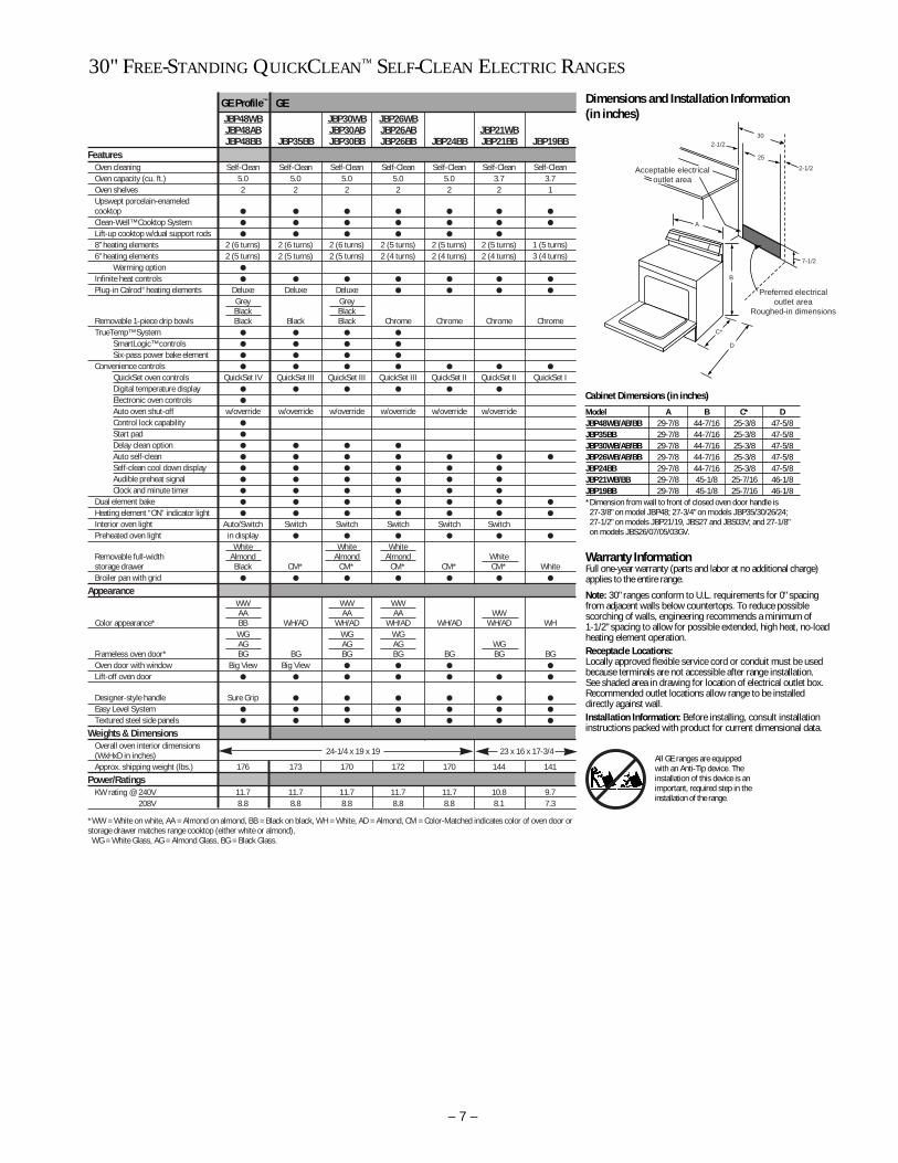
Dimensions and Installation Information (in inches)
Receptacle Locations: For 30” Free-Standing Ranges locally approvedflexible service cord or conduit must be used because terminals are notaccessible after range installation. See shaded area drawing for locationof electrical outlet box. Recommended outlet locations allow range tobe installed directly against wall.
Note: Conforms to U.L. requirements for 0” spacing for adjacent wallsbelow countertops. To reduce possibility of scorching of walls, it is recommended a minimum of 1-1/2” spacing be allowed from adjacentside walls to allow for possible extended, high-heat, no-load heatingelement operation.Installation Information: Before installing, consult installation instructions packed with range for current dimensional data.
All GE ranges are equippedwith an Anti-Tip device. Theinstallation of this device is animportant, required step in the installation of the range.
Model A B C* DJB970SB 30 48-1/4 26-5/8 45-1/8JB960WB/AB/BB 29-7/8 46-1/2 25-3/8 47-5/8JB940WB/AB/BB 29-7/8 46-1/2 25-3/8 47-5/8JBP79WB/AB/BB 29-7/8 46-1/2 25-3/8 47-5/8JBP78WB/AB/BB 29-7/8 44-7/16 25-3/8 47-5/8JBP66WB/AB/BB 29-7/8 44-7/16 25-3/8 47-5/8JBP64BB 29-7/8 44-7/16 25-3/8 47-5/8JBP63BB 29-7/8 44-1/2 25-7/16 46-1/8JBP60BB 29-7/8 44-1/2 25-7/16 46-1/8*Dimension from wall to front of closed oven door handle is 28-7/8" on model JB970; 27-3/8" on models JB960/940, JBP79;27-3/4" on models JBP78/66/64; and 27-1/2" on model JBP63/60.
Cabinet Dimensions (in inches)
INSTALLATION/SPECIFICATIONS FOR 30" FREE-STANDING CLEANDESIGN ELECTRIC RANGES
30
25
2-1/2
7-1/2
A
C*
D
B
2-1/2
Acceptable electricaloutlet area
Preferred electricaloutlet area
Roughed-in dimensions
QUICKSET I• Auto self-clean • 2-step self-clean • Preheated oven light • Dual element bake • Quick turn oven control • Platinum-tipped electronic oven sensor
QUICKSET IISame as QuickSet I, plus:• Digital temperature display with recall • Electronic digital clock • Electronic reminder timer, up to 12 hours • Audible Preheat signal • 12 hour automatic oven shut-off • Self-clean countdown digital display, includes cook down
QUICKSET IIISame as QuickSet II, plus:• Automatic oven control • Delay Bake • Delay Self-Clean • Adjustable self-clean cycle time
QUICKSET IVSame as QuickSet III, plus:• Automatic self-clean • All touchpad control • Large digital temperature display • Variable broil
QUICKSET VSame as QuickSet IV, plus:• Convection bake/roast • Temperature probe • Extra-large graphics and extra-large touchpads • Digital glass capacitance touch control (0-9) entry • Oven function icons
– 7 –
30" FREE-STANDING QUICKCLEAN™ SELF-CLEAN ELECTRIC RANGES
Note: 30" ranges conform to U.L. requirements for 0" spacingfrom adjacent walls below countertops. To reduce possiblescorching of walls, engineering recommends a minimum of 1-1/2" spacing to allow for possible extended, high heat, no-loadheating element operation.Receptacle Locations:Locally approved flexible service cord or conduit must be usedbecause terminals are not accessible after range installation. See shaded area in drawing for location of electrical outlet box.Recommended outlet locations allow range to be installeddirectly against wall.Installation Information: Before installing, consult installationinstructions packed with product for current dimensional data.
Warranty InformationFull one-year warranty (parts and labor at no additional charge)applies to the entire range.
Model A B C* DJBP48WB/AB/BB 29-7/8 44-7/16 25-3/8 47-5/8JBP35BB 29-7/8 44-7/16 25-3/8 47-5/8JBP30WB/AB/BB 29-7/8 44-7/16 25-3/8 47-5/8JBP26WB/AB/BB 29-7/8 44-7/16 25-3/8 47-5/8JBP24BB 29-7/8 44-7/16 25-3/8 47-5/8JBP21WB/BB 29-7/8 45-1/8 25-7/16 46-1/8JBP19BB 29-7/8 45-1/8 25-7/16 46-1/8*Dimension from wall to front of closed oven door handle is 27-3/8" on model JBP48; 27-3/4" on models JBP35/30/26/24;27-1/2" on models JBP21/19, JBS27 and JBS03V; and 27-1/8"on models JBS26/07/05/03GV.
Cabinet Dimensions (in inches)
Dimensions and Installation Information (in inches)
All GE ranges are equippedwith an Anti-Tip device. Theinstallation of this device is animportant, required step in theinstallation of the range.
GE Profile™ GE JBP48WB JBP30WB JBP26WBJBP48AB JBP30AB JBP26AB JBP21WBJBP48BB JBP35BB JBP30BB JBP26BB JBP24BB JBP21BB JBP19BB
FeaturesOven cleaning Self-Clean Self-Clean Self-Clean Self-Clean Self-Clean Self-Clean Self-CleanOven capacity (cu. ft.) 5.0 5.0 5.0 5.0 5.0 3.7 3.7Oven shelves 2 2 2 2 2 2 1Upswept porcelain-enameled cooktop
Clean-Well™ Cooktop System
Lift-up cooktop w/dual support rods
8" heating elements 2 (6 turns) 2 (6 turns) 2 (6 turns) 2 (5 turns) 2 (5 turns) 2 (5 turns) 1 (5 turns)6" heating elements 2 (5 turns) 2 (5 turns) 2 (5 turns) 2 (4 turns) 2 (4 turns) 2 (4 turns) 3 (4 turns)
Warming option
Infinite heat controls
Plug-in Calrod® heating elements Deluxe Deluxe Deluxe
Grey GreyBlack Black
Removable 1-piece drip bowls Black Black Black Chrome Chrome Chrome ChromeTrueTemp™ System
SmartLogic™ controls
Six-pass power bake element
Convenience controls
QuickSet oven controls QuickSet IV QuickSet III QuickSet III QuickSet III QuickSet II QuickSet II QuickSet IDigital temperature display
Electronic oven controls
Auto oven shut-off w/override w/override w/override w/override w/override w/overrideControl lock capability
Start pad
Delay clean option
Auto self-clean
Self-clean cool down display
Audible preheat signal
Clock and minute timer
Dual element bake
Heating element “ON” indicator light
Interior oven light Auto/Switch Switch Switch Switch Switch SwitchPreheated oven light in display
White White WhiteRemovable full-width Almond Almond Almond Whitestorage drawer Black CM* CM* CM* CM* CM* WhiteBroiler pan with grid
AppearanceWW WW WWAA AA AA WW
Color appearance* BB WH/AD WH/AD WH/AD WH/AD WH/AD WHWG WG WGAG AG AG WG
Frameless oven door* BG BG BG BG BG BG BGOven door with window Big View Big View
Lift-off oven door
Designer-style handle Sure Grip
Easy Level System
Textured steel side panels
Weights & DimensionsOverall oven interior dimensions (WxHxD in inches) 24-1/4 x 19 x 19 23 x 16 x 17-3/4
Approx. shipping weight (lbs.) 176 173 170 172 170 144 141
Power/RatingsKW rating @ 240V 11.7 11.7 11.7 11.7 11.7 10.8 9.7
208V 8.8 8.8 8.8 8.8 8.8 8.1 7.3
*WW = White on white, AA = Almond on almond, BB = Black on black, WH = White, AD = Almond, CM = Color-Matched indicates color of oven door orstorage drawer matches range cooktop (either white or almond),WG = White Glass, AG = Almond Glass, BG = Black Glass.
30
25
2-1/2
7-1/2
A
C*
D
B
2-1/2
Acceptable electricaloutlet area
Preferred electricaloutlet area
Roughed-in dimensions
– 8 –
40" ELECTRIC RANGES
40" Range Dimensions and Installation Information (in inches)
*Dimension from wall to front of closed oven door handle.**Includes required 4" door swing allowance for side-hinged
oven or storage compartment door.
Receptacle Locations: For all 40" Free-StandingRanges locally approved flexible service cord orconduit must be used because terminals are notaccessible after range installation. See shadedarea in drawing for location of electrical outletbox. Recommended outlet locations allow rangeto be installed directly against rear wall.
Warranty InformationFull one-year warranty (parts and labor at no additional charge) applies tothe entire range. See written warranty for complete details.JCP67Y JCS57Y
FeaturesMaster Oven—Self-Clean
Oven cleaning Companion Oven—Standard Standard Master Oven—2
Oven shelves Companion Oven—1 Master Oven—28" heating elements 2 26" heating elements 2 2Removable drip bowls One-Piece Chrome One-Piece ChromeClock and minute timer Electronic ElectronicAutomatic oven timer MasterHeating element “ON” indicator light
Interior oven light
Full-width fluorescent cooktop night light
Oven cycling light 2
Storage drawer
Master Oven—1Broiler pan with grid Companion Oven—1 Master Oven—1
AppearanceColor appearance* WW WWOven door with window Master Oven
Lift-off oven door Master
Weights & DimensionsMaster Oven—
22-5/8 x 15-7/8 x 18-1/8Overall oven interior dimensions Companion Oven—(WxHxD in inches) 9-9/16 x 16 x 19-1/2 22-5/8 x 15-7/8 x 18-1/8Approx. shipping weight (lbs.) 224 197
Power/RatingsKW rating @ 240V 14.2 12.6
208V 10.7 9.5*WW = White on white.
GE
30" FREE-STANDING QUICKCLEAN™ STANDARD CLEAN ELECTRIC RANGES
GE JBS27WYJBS27AY JBS03GVJBS27BY JBS26W JBS23BB JBS07V JBS05Y JBS03V JBS02BB
FeaturesOven cleaning Standard Standard Standard Standard Standard Standard StandardOven capacity (cu. ft.) 3.7 3.7 3.7 3.5 3.7 3.7 3.7Oven shelves 2 2 2 2 2 2 1Upswept porcelain-enameled cooktop
Clean-Well™ Cooktop System
Lift-up cooktop w/dual support rods
8" heating elements 2 (6 turns) 1 (6 turns) 2 (6 turns) 1 (6 turns) 1 (6 turns) 1 (6 turns) 1 (6 turns)6" heating elements 2 (5 turns) 3 (5 turns) 2 (5 turns) 3 (5 turns) 3 (5 turns) 3 (5 turns) 3 (5 turns)Infinite heat controls
Plug-in Calrod® heating elements
Removable 1-piece drip bowls Chrome Chrome Chrome Chrome Chrome Chrome ChromeClock and minute timer
Dual element bake
Heating element “ON” indicator light
Interior oven light Switch Switch Switch Switch Auto/SwitchWhite
Removable full-width Almondstorage drawer CM* CM* CM* White CM* CM* CM*Broiler pan with grid
AppearanceWWAA
Color appearance* WH/AD WH/AD WH/AD WW WH/AD WH/AD WHWGAG BG
Frameless oven door* BG CM BG White CM CM BGOven door with window
Lift-off oven door
Designer-style handle Visor Visor Visor Visor Visor VisorEasy Level System
Textured steel side panels
Weights & DimensionsOverall oven interior dimensions 23 x 16 x 23 x 16 x 22-3/4 x 23 x 16 x 23 x 16 x(WxHxD in inches) 23 x 16 x 17-7/8 17-3/4 17-7/8 15-3/4 x 17 17-7/8 17-3/4
141Approx. shipping weight (lbs.) 141 144 146 141 153 139 141
Power/RatingsKW rating @ 240V 10.9 9.8 10.4 9.8 9.3 9.8 9.8
208V 8.4 7.4 8.4 7.4 6.9 7.4 7.6*WW = White on white, AA = Almond on almond, BB = Black on black, WH = White, AD = Almond, CM = Color-Matched indicates color of oven door orstorage drawer matches range cooktop (either white or almond),WG = White Glass, AG = Almond Glass, BG = Black Glass.
Model A B C* DJBS27WY/AY/BY 29-7/8 45-1/8 25-7/16 46-1/8JBS26W 29-7/8 45-1/8 25-5/16 46-3/8JBS23BBJBS07V 29-7/8 45-1/8 25-5/16 46-3/8JBS05Y 29-7/8 44-5/8 25-5/16 45-1/2JBS03GV 29-7/8 45-1/8 25-5/16 46-1/8JBS03V 29-7/8 45-1/8 25-5/16 46-3/8JBS02BB*Dimension from wall to front of closed oven door handle is 27-3/8" on model JBP48; 27-3/4" on models JBP35/30/26/24;27-1/2" on models JBP21/19, JBS27 and JBS03V; and 27-1/8"on models JBS26/07/05/03GV.
Cabinet Dimensions (in inches)
Dimensions and Installation Information (in inches)
30
25
2-1/2
7-1/2
A
C*
D
B
2-1/2
Acceptable electricaloutlet area
Preferred electricaloutlet area
Roughed-in dimensions
CL
7" MAX.
10
10Wall
of range
Locate outletin shaded area.Wall mount only.
Floor
20
40-1/8
4
Top View44-1/8**
40-1/8
47-1/4
27-3/8*
18-1/2
All GE ranges are equippedwith an Anti-Tip device. Theinstallation of this device is animportant, required step in theinstallation of the range.
– 9 –
Using the convection oven.The convection oven fan shuts off when the oven door is opened. DO NOT leave the door open for long periods of time while using convectioncooking or you may shorten the life of the convection heating element.
To help you understand the difference betweenconvection bake and roast and traditional bake androast, here are some general guidelines.
Convection Bake Ideal for evenly browned baked foods cooked on all 3 shelves. Good for large quantities of baked foods. Good results with cookies, biscuits, muffins, brownies, cupcakes,
cream puffs, sweet rolls, angel food cake and bread.Heat comes from the heating element in the rear of theoven. The convection fan circulates the heated airevenly, over and around the food. Preheating is notnecessary with foods having a bake time of over 15minutes.
Convection Roast Good for large tender cuts of meat, uncovered.Heat comes from the top heating element. Theconvection fan circulates the heated air evenly over andaround the food. Meat and poultry are browned on allsides as if they were cooked on a rotisserie. Using theroasting rack provided, heated air will be circulatedover, under and around the food being roasted. Theheated air seals in juices quickly for a moist and tenderproduct while, at the same time, creating a rich goldenbrown exterior.
Roasts or poultry should be cooked on the lowest shelf position (A) on a shelf.
When you are convection roasting it is important thatyou use the broiler pan and grid and the special roastingrack for best convection roasting results. The pan is usedto catch grease spills and the grid is used to preventgrease spatters. Place the meat on the special roastingrack. The rack holds the meat. The rack allows theheated air to circulate under the meat and increasebrowning on the underside of the meat or poultry.
Place the shelf in the lowest shelf position (A).
Place the grid on the broiler pan and put the roastingrack over them making sure the posts on the roastingrack fit into the holes in the broiler pan.
In a convection oven, a fan circulateshot air over, under and around thefood. This circulating hot air is evenlydistributed throughout the oven cavity.As a result, foods are evenly cookedand browned—often in less time withconvection heat.
You can use your favorite recipes in the convection oven. Recipeconversion is as easy as 1, 2, 3.
When baking, reduce baking temperature by 25˚ F.
No need to preheat when cooking longer than 15 minutes.
For more information on adapting recipes, see the Convection Cookbook.
Use pan size recommended.
Some package instructions for frozen casseroles or main dishes have been developed using commercial convection ovens. For best results in this oven, preheat the oven and use the temperature on the package.
21
Adapting Recipes…
Before using your convection oven, check to see if your cookwareleaves room for air circulation in the oven. If you are baking withseveral pans, leave space between them. Also, be sure the pans donot touch each other or the walls of the oven.
Paper and Plastic
Heat-resistant paper and plastic containers that are recommendedfor use in regular ovens can be used in convection ovens. Plastic cookware that is heat-resistant to temperatures of 400˚ F. can also be used.
Metal and Glass
Any type of cookware will work in your convection oven. However, metal pans heat the fastest and are recommended for convection baking.
Darkened or matte-finished pans will bake faster than shiny pans.
Glass or ceramic pans cook more slowly.
When baking cookies, you will get the best results if you use a flatcookie sheet instead of a pan with low sides.
For recipes like oven-baked chicken, use a pan with low sides. Hotair cannot circulate well around food in a pan with high sides.
Cookware for Convection Cooking

– 10 –
Using the convection oven.How to Set the Oven for Convection Baking or Roasting
Press the CONVECTION BAKE or CONVECTIONROAST pad.
Press the number pads to set the desired oven temperature.
Press the START pad.
To change the oven temperature, press the CONVECTION BAKE or CONVECTION ROAST pad and then the number pads to set the new temperature.
When the oven starts to heat the changing temperature,starting at 100 F., will be displayed. When the ovenreaches the temperature you set, 3 beeps will sound.
Press the CLEAR/OFF pad when finished.
NOTE: You will hear a fan while cooking with convection. The fan will
stop when the door is opened but the heat will not turn off. You may hear the oven clicking during baking. This is normal.
4
3
2
1
Multi-Shelf Baking
How to Set the Oven for Convection Roastingwhen Using the ProbeDo not lock the oven door with the latch during convection roasting.The latch is used for self-cleaning only.
The display will flash PROBE and the oven control will signal if the probe is inserted into the outlet, and youhave not set a probe temperature and pressed the START pad.
Place the shelf in the lowest position (A). Insert theprobe into the meat.Plug the probe into the outlet on the oven wall. Makesure it is pushed all the way in. Close the oven door.Touch the CONVECTION ROAST pad.
Touch the number pads to set the desired internalprobe temperature.Touch the PROBE pad.
Touch the number pads to set the desired internalfood temperature.Touch the START pad.
When the oven starts to heat, the word LO will showin the display. After the internal temperature of the food reaches 100˚ F., the changing internal temp-erature will show in the display.
When the internal temperature of the food reachesthe number you have set, the probe and the oventurn off and the oven control signals. To stop thesignal, press the CLEAR/OFF pad. Use hot pads to remove the probe from the food. Do not use tongsto pull on it—they might damage it.
CAUTION: To prevent possible burns, do not unplug the probe fromthe oven outlet until the oven has cooled. Do not store probe in oven
NOTE: If the probe is removed from the food before the final
temperature is reached, a tone will sound and the display will flash until the probe is removed from the oven.
You will hear a fan while cooking with this feature. The fan willstop when the door is opened but the heat will not turn off.
You can use the timer even though you cannot use timed oven operations while using the probe.
8
7654321
For best results when roasting largeturkeys and roasts, we recommendusing the probe included in theconvection oven.
To change the oven temperatureduring the Convection Roast cycle,press the CONVECTION ROAST padand then press the number pads to set the new desired temperature.
START
CLEAROFF
Because heated air is circulated evenly through out the oven, foods can be baked with excellent results using multiple shelves.
Multi-shelf baking may increase cook times slightly for some foods but the overall result is time saved. Cookies, muffins, biscuits, and other quick breads give very good results with multi-shelf baking.
When baking on 3 shelves, place one shelf in the bottom (B), one on the 4th (D) position and the offset shelf in the 6th (F) position.
When convection baking with only 1 shelf, follow the shelf positionsrecommended in the Using the oven section.
START
CLEAROFF
– 11 –
Convection roasting guide.
*
†
Using Convection ConversionBy using the Convection Conversion feature you can automaticallyconvert the oven temperature from regular baking to ConvectionBake temperatures.
To convert the oven temperature for convection baking,follow the steps below.
Press and hold the CONVECTION BAKE pad for 4 to 5 seconds.
Using the number pads enter the temperaturerecommended in the recipe.
Press the START pad.
The display shows the converted (reduced)temperature. For example, if you entered a recipetemperature of 350˚ F., the display will show 325˚ F.when it is converted.
Press the CLEAR/OFF pad when baking is finished.
NOTE: Conversion must be set each time you want to use it. It isnot held in memory.
4
3
2
1
Stuffed birds generally require 30-45 minutes additional roasting time. Shield legs and breast with foil to prevent over-browning and drying of skin.
The U.S. Department of Agriculture says "Rare beef is popular, but you should know that cooking it to 140˚ F. means some food poisoning organisms may survive." (Source: Safe Food Book. Your Kitchen Guide. USDA Rev. June 1985.)
START
CLEAROFF
Convection Roasting Guide
Meats Minutes/Lb. Oven Temp. Internal Temp.Beef Rib (3 to 5 lbs.) Rare† 20–24 325˚F. 140˚F.
Medium 24–28 325˚F. 160˚F.Well 28–32 325˚F. 170˚F.
Boneless Rib, Top Sirloin Rare† 20–24 325˚F. 140˚F.Medium 24–28 325˚F. 160˚F.
Well 28–32 325˚F. 170˚F.Beef Tenderloin Rare† 10–14 325˚F. 140˚F.
Medium 14–18 325˚F. 160˚F.Pot Roast (2½ to 3 lbs.) chuck, rump 35–45 300˚F. 170˚F.
Pork Bone-in (3 to 5 lbs.) 23–27 325˚F. 170˚F.Boneless (3 to 5 lbs.) 23–27 325˚F. 170˚F.Pork Chops (1/2 to 1″ thick) 2 chops 30–35 total 325˚F. 170˚F.
4 chops 35–40 total 325˚F. 170˚F.6 chops 40–45 total 325˚F. 170˚F.
Ham Canned (3 lbs. fully cooked) 14–18 325˚F. 140˚F.Butt (5 lbs. fully cooked) 14–18 325˚F. 140˚F.Shank (5 lbs. fully cooked) 14–18 325˚F. 140˚F.
Lamb Bone-in (3 to 5 lbs.) Medium 17–20 325˚F. 160˚F.Well 20–24 325˚F. 170˚F.
Boneless (3 to 5 lbs.) Medium 17–20 325˚F. 160˚F.Well 20–24 325˚F. 170˚F.
Seafood Fish, whole (3 to 5 lbs.) 30–40 total 400˚F.
Lobster Tails (6 to 8 oz. each) 20–25 total 350˚F.Poultry Whole Chicken (2½ to 3½ lbs.) 24–26 350˚F. 180˚–185˚F.
Cornish Hens Unstuffed (1 to 1½ lbs.) 50–55 total 350˚F. 180˚–185˚F.Cornish Hens Stuffed (1 to 1½ lbs.) 55–60 total 350˚F. 180˚–185˚F.
Duckling (4 to 5 lbs.) 24–26 325˚F. 180˚–185˚F.
Turkey, whole*Unstuffed (10 to 16 lbs.) 8–11 325˚F. 180˚–185˚F.Unstuffed (18 to 24 lbs.) 7–10 325˚F. 180˚–185˚F.
Turkey Breast (4 to 6 lbs.) 16–19 325˚F. 170˚F.

– 12 –
Cleaning the glass cooktop.Clean the glass surface with cleaning cream before you use the cooktop for the first time. Also, clean the glass surface after each use. This helps protect the top and makes clean-up easier.
To clean the cooktop seal around the edge of the glass, let a wet cloth rest on it for a few minutes, then wipe clean.Use a mild detergent if needed.
Do not use a knife or any sharp object on the seal because it will cut or damage it.
Normal CleaningUse only a recommended cleaning cream,such as Cerama Brite or another cooktopcleaning cream, on the glass cooktop.
To maintain and protect the surface ofyour new glass cooktop follow these steps.
Before you use the cooktop for thefirst time, clean it with cleaningcream. This helps protect the topand makes clean-up easier.
Clean the surface with the cleaningcream after each use.
Rub a few drops (less is better) of thecleaning cream onto soiled areausing a damp paper towel. Buff witha dry paper towel until all soil andcream are removed.
For Heavy, Burned-On Soil…Allow the cooktop to cool.
Apply a few drops of the cleaningcream to the (cool) soiled area.
Using a damp paper towel, rub thecream into the burned-on area. Aswith any burned-on spill, this mayrequire some effort.
Carefully scrape soil with razorscraper. Hold scraper at a 30˚ angleagainst the glass cooktop.
Be sure to use a new sharp razor scraper. Do notuse a dull or nicked blade.
If any soil remains, repeat the stepslisted above. For additionalprotection, after all soil has beenremoved, polish the entire surfacewith the cleaning cream.
Buff with a dry paper towel.
To order more cream and/or scrapers forcleaning your glass cooktop, please callour toll-free number:
National Parts Center . . . . . . . . .800-626-2002
Cleaner . . . . . . . . . . . . . . . . . . . . . .# WX10X300Scraper . . . . . . . . . . . . . . . . . . . . .# WX5X1614Cream & scraper kit . . . . . . . . .# WB64X5027
Special CareBe sure to use a new sharp razor scraper. Do notuse a dull or nicked blade.
Sugary spillovers (such as jellies, fudge,candy syrups) or melted plastics cancause pitting of the surface of yourcooktop (not covered by the warranty)unless the spill is removed while still hot.Special care should be taken whenremoving hot substances.
Turn off all surface units affected bythe spillover. Remove hot pans.
Wearing an oven mitt, hold the razorscraper at a 30˚ angle to the cooktop.Scrape the hot spill to a cool areaoutside the surface unit.
With the spill in a cool area, use a drypaper towel to remove any excess.Any spillover remaining should beleft until the surface of the cooktophas cooled. Do not continue to usethe soiled surface unit until all of thespillover has been removed. Followthe steps under Heavy Burned-On Soilto continue the cleaning process.
NOTE: If pots with a thin overlay of aluminum,copper or enamel are allowed to boil dry, theoverlay may bond with the glass cooktop andleave a black discoloration. This should beremoved immediately before heating again or the discoloration may be permanent.
Using a razor scraper will notdamage the surface if the 30˚ angleis maintained.
Using the self-cleaning oven.The oven door must be closed and all controls set correctly for the cycle to work properly.
Before a Clean CycleWe recommend venting your kitchenwith an open window or using aventilation fan or hood during the firstself-clean cycle.
Remove the shelves, broiler pan, broilergrid, probe, all cookware and anyaluminum foil from the oven.
The oven shelves and convection roastingrack can be self-cleaned, but they willdarken, lose their luster and becomehard to slide.
Soil on the front frame of the range andoutside the gasket on the door will needto be cleaned by hand. Clean these areaswith hot water, soap-filled steel-wool padsor cleansers such a Soft Scrub®. Rinse wellwith clean water and dry.
Do not clean the gasket. The fiberglassmaterial of the oven door gasket cannotwithstand abrasion. It is essential for thegasket to remain intact. If you notice itbecoming worn or frayed, replace it.
Wipe up any heavy spillovers on the ovenbottom.
Make sure the oven light bulb cover is inplace and the oven light is off.
IMPORTANT: The health of some birds isextremely sensitive to the fumes given offduring the self-cleaning cycle of anyrange. Move birds to another wellventilated room.
Wipe up heavy soil on the ovenbottom.
How to Set the Oven for CleaningTouch the SELF CLEAN pad.
Using the number pads, enter thedesired clean time, if a time otherthan 4 hours, 30 minutes is needed.
Clean cycle time is normally 4 hours, 30minutes. You can change the clean timeto any time between 3 hours and 5 hours,depending on how dirty your oven is.
Touch the START pad.
The door locks automatically. The displaywill show the clean time remaining. It willnot be possible to open the oven door until the temperature drops below the lock temperature and the LOCKED DOORlight goes off.
When the LOCKED DOOR light is off, openthe door.
The oven shuts off automatically whenthe clean cycle is complete.
The words LOCK DOOR will flash andthe oven control will signal if you set the clean cycle and forget to close theoven door.
To stop a clean cycle, touch theCLEAR/OFF pad. When the LOCKEDDOOR light goes off indicating the oven has cooled below the lockingtemperature, open the door.

– 13 –
COOKTOP LIGHT REPLACEMENT
To Remove The Old Bulb:1. Remove power to the unit.2. Pull the range away from the wall.3. Remove the two screws from the top edge
on the back of the range (A).4. Pull up on the hand grips on the back of
the range (B) until the tabs at the bottomof the cooktop light housing separate fromthe back of the range.
5. Pull out the cooktop light housing as far aspossible - approx. 2 inches (C).
6. Remove the light bulb by unplugging it fromboth sockets with one motion.
To Install The New Bulb:1. Install the new light bulb by plugging it into
both sockets with one motion.2. Using the hand grips on the cooktop light
housing (D), lift up and push the housingback into the rear wall of the range. Thenlower the housing until the bottom tabs areinserted back into the range.
3. Reinstall the two screws along the top edgeon the back of the range.
OVEN DOOR REMOVAL
The oven door is locked to the range cabinetwith hinge locks, located on top of both doorhinges.
To Remove The Oven Door:1. Fully open the oven door.2. Push the hinge locks down toward the door
frame, to the unlocked position.3. Raise the door to the broil position.4. Firmly grasp both sided of the door about
center ways down the door and lift upwardsto disengage the hinge arm from the hingeslot. At the same time, pull the door to-wards you while lifting it away from therange.
To Reinstall Oven Door:1. Firmly grasp both sides of the door and
insert the hinge arms into the door hingeslots, while holding the door angle in thebroil position.
2. Lower the hinge arms downward, aligningthe hinge arm indentation to the lower por-tion of the hinge slot.
3. Fully open the door.4. Push the hinge locks up against the front
frame of the oven cavity, to the locked po-sition.
SCREWS
A
2"HANDGRIPS
COOKTOPLIGHT
HOUSING
B
LIGHT BULB
SOCKET
C
COOKTOPLIGHT
HOUSING
HANDGRIPSD
HINGE LOCK(UNLOCKED POSITION)
HINGE LOCK(LOCKED POSITION)
SLOT
HINGE ARM SEATED HINGEARM
LOWER HINGE ARMINTO HINGE SLOT

– 14 –
COOKTOP REMOVAL
The ceramic glass cooktop is sealed into theporcelain cooktop frame and is not replaceableas a separate part. The cooktop comes as acomplete assembly (porcelain frame and ce-ramic glass).
To remove the cooktop:1. Remove power to the unit.2. Remove the two screws which secure the
cooktop to the front frame.3. Lift the front of the cooktop upward (no
more than 45°). NOTE: lifting the front ofthe cooktop too high, can break the glass.
4. Unplug the two electrical connector plugsand remove the ground wire from thecooktop (located at the rear of thecooktop).
5. While grasping both sides of the cooktop,lift the front of the cooktop upward approxi-mately 30 to 40° (see illustration A, lowerright).
6. While holding the front of the cooktop up-ward, lower the rear of the cooktop in or-der to disengage the cooktop hinges fromthe hinge pins (see illustration B, lowerright).
7. Once the cooktop hinges are disengagedfrom the hinge pins, lift the rear of thecooktop upward and over the hinge pinswhile pulling the cooktop forward to remove(see illustration C, lower right).
Once the cooktop is removed, the oven venttube, and latch motor assembly are accessible.
Important note: prior to reinstalling the cooktop,study the hinge mechanism for a few moments,noting the location of the hinge pins and thedesign of the hinges. Doing so will allow for amuch easier reinstallation.
COOKTOP REMOVAL
HINGE
HINGEPIN
A
B
C
LIFT UPWARDSON FRONT OF
COOKTOP TO A45˚ ANGLE
LOWER THE REAROF THE COOKTOP
TO DISENGAGETHE HINGES FROM
THE HINGE PINS
LIFT THE COOKTOPUPWARDS AND
OVER THE HINGEPINS

– 15 –
A
B
C
HIDDEN BAKE ELEMENT
The bake element is located underneath theoven liner (hidden bake), where it is protectedfrom spillage and oven cleaning agents whichcan shorten the life of the element.
The bake element is accessible from the left side(facing the unit) of the range. To access the bakeelement, carefully remove the range from its in-stallation taking care to protect the customer’sfloor.
Bake Element Removal:
1. Remove power to the unit.2. Remove the cooktop following the instruc-
tions outlined on page 14.3. Remove the seven screws shown in the
illustration to the right.4. At the front corner of the panel, near the
leveling leg, is a hidden screw . Access tothis screw is obtained by removing the stor-age drawer. From inside the storagedrawer area, located just above the leftfront leveling leg (as you face the unit), aretwo 1 inch holes. If you shine a light intothe top hole you will be able to see the ¼inch hex screw that will need to be re-moved, in order to remove the side panel.
5. Facing side of the panel, grasp the frontand rear portion of the panel. Pull the rearof the panel towards you (A) approximately2-3 inches, while lifting upwards on the frontof the panel (B) approximately 1 inch. No-tice in the illustration to the right that thepanel is held to the range frame with 2 ny-lon grommets (top and center of panel),which fit into holes in the side panel. Bylifting upwards on the front panel (B), whileat the same time pulling the panel towardsyou (C), you are able to disengage thepanel from the rubber grommets.
HIDDEN BAKE
PH
ILLI
PS
#10
TOR
X
¼ H
EX
¼ HEX
¼ HEX
¼ HEX
¼ HEX
– 16 –
Bake Element Removal (cont.)
6. Disconnect the electrical terminals from thebake element and remove the bake ele-ment wires from the retaining clip on themetal cover plate (remember to reinstall thewires back into the retainer clip during re-installation to prevent pinched wires). Re-move the four ¼ inch hex screws whichsecure the metal insulation cover plate tothe frame. Remove the metal plate.
Note: that one of the screws holding themetal plate to the frame, also secures aground wire to the cabinet. Also notice thatthe frame has two locator tabs which alignthe plate to the frame during reinstallation.
7. Using rubber gloves to protect your hands,carefully grasp the insulation which cov-ers the side of the range and roll it upwardsto the top of the range. Tuck the end of itunder the brace which runs from the frontof the oven to the back of the oven. Thiswill hold the insulation in place while youservice the bake element.
8. Remove the two screws which mount andsecure the bake element to the frame.Note: remember the screw on the left isthe one which secures the ground wire.Don’t forget to reattach this wire when re-installing the bake element (this is the otherend of the ground wire referred to in step5).
9. Grasp the retaining channel on the left sideand swing it outwards and to the left. No-tice that the channel is hinged on the rightside (fits into a slot in the frame). You arenow able to see into the area which housesthe bake element.
LOCATORTABS
GROUNDWIRE
BAKE ELEMENTWIRES
BAKE ELEMENTWIRE RETAINER
CLIP
INSULATION
GROUNDWIRE
RETAINING CHANNEL

– 17 –
Bake Element Removal (cont.)
10. Grasp the bake element on both sides andgently pull it towards you as you removeit from its housing. IMPORTANT: noticethat the opposite end of the bake elementhas two alignment tabs which must fit intoslots on the other side of the housing.When reinstalling the element, be surethat the tabs are engaged into the locatorslots on the opposite end. If you fail to dothis, the bake element will not fit flushagainst the frame and will protrudeenough that you will not be able to re-mount it to the frame.
Tip: The bottom area of the bake ele-ment housing bows slightly upward in thecenter - this is due to insulation under-neath it which forces it slightly upward.Using a long bladed screw driver, gentlypush downward on the bake elementhousing while pushing the element for-ward. This is also helpful in forcing thebackside of the element downwardenough so that it can align with the loca-tor slots on the opposite side.
NOTE: TWO LOCATOR TAB SLOTS
REFLECTORPAN
BAKEELEMENT
INSULATION
ALIGNMENTCHANNELS
LOCATORSLOT
LOCATORTAB

– 18 –
DOOR SWITCH REMOVAL
The door switch can be accessed through twomethods. If you have small hands you can ac-cess the switch from the top of the range. If youhave large hands, you will need to remove theleft side of the range to access the switch.
If You Have Small Hands:1. Remove the cooktop.2. Remove the bracket across the top/front
of the range. This bracket is held in placewith 6 torx screws. Once the bracket isremoved, you can access the switch.
3. To remove the switch, depress inward onthe locking tabs while pulling outward onthe switch body.
If you Have Large Hands:1. Remove the cooktop.2. Remove the left side panel of the range.3. To remove the switch, depress inward on
the locking tabs while pulling outward onthe switch body.
OVEN LINER REMOVAL
Should it ever become necessary to replace theoven liner (customer damage), you can do so,following the steps listed below:
1. Remove the cooktop.2. Remove both side panels and metal cov-
ers (metal insulation covers).3. Remove the bake element.4. Remove two ¼ inch screws in the back of
the cabinet (A) which secure the liner tothe rear wall of the range.
5. From the back of the range disengage thetwo metal hooks of the liner, which engageinto the back wall of the range (B). Do thisby pushing upward on the hooks with ametal object (screwdriver blade) whilepushing forward at the same time
6. From the back of the range, disengage theoven lamp clip which secures the lamp tothe rear wall of range (C).
7. From the back of the range, remove thefollowing.
a. Convection fan wiring (caution: term- inal connections are tight & fragile).b. Oven lamp wiringc. Sensor wiring (disconnect plug)d. Broil element wiringe. Convection element wiring
DEPRESS SWITCHLOCKING TABSTO RELEASE
A AB B
C
BACK OF RANGE WITH ELECTRICALSHIELD AND LAMP SOCKET COVER
REMOVED

– 19 –
Oven Liner Removal (cont).
8. Remove 7 screws from inside the ovencavity (see illustration to right), which se-cure the oven liner to the frame/cabinet (1on each front side of the liner, 2 on lowerback wall of liner and 3 across the top frontof the liner).
9. From inside the oven cavity, remove thesmoke eliminator chimney (2 screws).
10. Remove the oven vent chimney - if this isnot removed the oven liner can catch on itduring reinstallation.
11. Remove the meat probe recepticle frominside the oven cavity top (2 screws).
12. Remove the two front screws which se-cure the front edge of the broil elementbracket to the top of the oven liner (do notremove the screws which mount the broilelement to the back wall).
13. Gently pull the liner forward, making sureto keep the liner evenly spaced on eachside as you pull it forward. Note: you willbe removing the oven liner with the broilelement, convection fan assembly, andoven lamp assembly still mounted to theliner.
OVEN LINER REINSTALLATION
1. After transfering the convenction fan as-sembly, lamp assembly, sensor, and broilelement to the new liner; slide the new linerback into the cabinet frame.
2. Install the two screws from the back of therange which secure the oven liner to theoven frame, taking care to ensure that the2 liner hooks catch into the slots in the backwall of the oven.
3. Install the two screws which mount theoven liner to the bake element housing pan(2 screw holes located inside oven liner,lower back wall). You will need to move/adjust the bake element housing pan inorder to line up the holes in the liner withthose in the pan.
4. Reinstall the oven vent and smoke elimi-nator chimney, taking care to properlymate the chimney to the oven vent locateddirectly above it (secured with 2 screws).
5. Reinstall the meat probe receptical, andall remaining interior oven liner hardware.
6. Reinstall the bake element and cooktop,taking care to reconnect all ground strapsand ensure that all wiring is relocated backinto its original holding restraints.

– 20 –
CONTROL PANELThe electronic touch controls, located on the frontof the control console, are capacitance touchdesign. The crystal keypanel assembly has thecapacitance touch circuit board bonded to itssurface on the rear side.
Keypanel Removal
1. Remove power to the unit.2. Remove all four control knobs.3. Remove the four nylon retainer nuts which
secure the crystal keypanel assembly tothe control console. Important note:when reinstalling the nylon retainer nuts,tighten only hand tight. Be sure that eachnylon retainer nut is flush with the glasskeypanel (the shoulder of the nylon re-tainer nut is seated into the glasskeypanel). Over tightening can damagecrystal keypanel assembly.
4. With all four nuts removed, the keypanelassembly can now be pulled away fromthe control console to gain access to theconnector plug. This plug connects thekeypanel to the ERC (Electronic RangeControl).
Control Panel Access
1. Remove power to the unit.2. Lay a protective cloth on the cooktop sur-
face.3. To obtain access to the control panel com-
ponents, remove the four screws whichsecure it to the range frame (see illustra-tion to the right). Gently pull forward fromthe bottom the control panel while liftingupward.
4. Lay the control panel on the protectedcooktop surface (components facing up-ward).
Infinate Heat Switch Removal
1. Remove power to the unit.2. Remove the crystal keypanel assembly
following the steps listed above.3. Remove the crystal mounting plate which
secures the infinate heat switch to the con-trol console (2 small phillips head screws).
CONTROL PANELACCESS
CONTROLKNOB
NYLONRETAINER
NUT
CRYSTALMOUNTING
PLATE

– 21 –
THERMAL LIMITERSWITCH
THERMAL LIMITERSCHEMATIC
L2
Therm.Limit Sw.
Hot Light
SURFACEELEMENT
REAR
HI8
8HI
FRONTBURNER
BRIDGEBURNER
664
2LO LO 2
4
OFF
FRONT HOT
HOT LIGHT LOCATIONS
INFINITE HEAT CONTROLS
Infinite heat controls are used to regulate thewattage of the surface units. The infinite heatcontrol is essentially a timing device, and its on-off time is not related to any temperature sens-ing element at the surface unit (such as the sen-sor head of an automatic surface unit).
The controls have two detent positions - OFFand HIGH. Between the these two positions isan infinite range of heat selections. At the highdetent setting, the surface unit is energized con-tinuously.
There are two basic types of infinite heat con-trols used on the new Spectra™ series of ranges.One is a Voltage Sensitive control and the otheris a Current Sensitive control.
Internally both controls (voltage sensitive andcurrent sensitive) contain a bi-metal control whichregulates the switch ON-OFF time. The bi-metalhas a heater wrapped around it which suppliesheat to the bi-metal, opening and closing thecontrol cycling contacts. As you will note fromthe illustrations to the right, the heater is onlyenergized when the cycling contacts areclosed.
THERMAL LIMITER SWITCH
Attached to each surface element is a thermallimit switch. This switch serves two purposes.
1. Controls cooktop surface “HOT” light op-eration.
2. Removes power to the surface element, inthe event that the cooktop glass directlyabove the element exceeds 1031° F.
When the temperature of the cooktop glass,above the heating element, reaches 150° F., aset of contacts in the thermal switch will closeand provide power to the HOT light. The hotlight will remain on until the glass surface abovethe element cools below 150° F. The HOT lightis mounted to the control panel and is locatedjust below each control knob (see Illustration tothe right).
The second set of contacts in the thermal limitswitch remove power to the element in the eventthe cooktop glass above the element exceeds1031° F. If this condition should ever occur thecontacts in the thermal limit switch will open andremove power to the element. Once the cooktopglass cools below 1031° F., the contacts in thethermal limit switch will close and the elementwill resume operation.
H1
P
H2
L2L1
CURRENTSENSITIVE
L2L2
N
PILOT
P
H1
H2
L1L1
RRSURFACE
UNIT
< 1 Ω
L2
5 N
2 3
L1L1
H1
TOP
4P
L2
H2N
4
32
GRND
5P
H2
H1GRND
CYCLINGCONTACT
10.45 KΩ
VOLTAGESENSITIVE
LF S
URFA
CE E
LEM
ENT
BRID
GE E
LEM
ENT
VOLTAGE SENSITIVE
H1
P
H2
L1 L2
TOP
L1
P
N
PILOT
L2 H2
H1
LRSURFACE
UNIT15.59K Ω

– 22 –
12 HOUR SHUT-OFFWith this feature, should you forget and leave the oven on, the control will automatically turn off the oven after 12 hours, during baking functions, or after 3 hours during a broil function. If you wish to turn off this feature, follow the steps below:
Press the BAKE and BROIL HI/LO pads at the same time for 2 seconds until the display shows "SF".Press the DELAY START or START TIME pad. The display will show "12 Shdn" (12 hour shut-off). Press the DELAY START or START TIME pad again and the display will show "no Shdn" (no shut-off).Press the START pad to activate the no shut-off and leave the control set in this special features mode.
ERC V SPECIAL FEATURES
COOKING/SELF-CLEAN LOCKOUTThe ERC control will allow you to lock out the COOKING and SELF CLEAN pads so that they cannot be activated when touched.
Press the BAKE and BROIL HI/LO pads at the same time for 3 seconds until the display shows "SF".Press the SELF CLEAN pad. The display will show "Loc OFF." If this is your choice, press START.Press the SELF CLEAN pad again. The display will show "Loc On." If this is your choice, press START.When this feature is on and the touch pads are pressed the control will beep and the display will show "LOC."NOTE: The control lockout mode will not affect the clock, kitchen timer on/off and oven light touch pads
12 HOUR, 24 HOUR OR CLOCK BLACK-OUTThe ERC control is set to use a 12 hour clock. If the customer prefers to have a 24 hour military time clock or black-out the clock display, follow the steps below.
Press the BAKE and BROIL HI/LO pads at the same time for 2 seconds until the display shows "SF".Press the CLOCK pad once. The display will show "12 hr."Press the CLOCK pad again to change to the 24 hour military time clock. The display will show "24 hr." If this is your choice, press START.Press the CLOCK pad again to black-out the clock display. The display will show "OFF." If this is your choice, press START.If the clock is in the black-out mode and you want to restore it to the display, repeat steps 1 and 2.NOTE: If the clock is in the black-out mode you will not be able to use the DELAY START function.
TO ADJUST THE THERMOSTAT (MODELS WITH NUMBER PADS)
Press the BAKE and BROIL HI/LO pads at the same time for 2 seconds until the display shows "SF".Press the BAKE pad. A two digit number shows in the display. Press the BAKE pad once to increase (+) the oven temp. or twice to decrease (-).The oven temp. can be adjusted up to (+) 35˚F. hotter or (-) 35˚F. cooler. Press the number pads the same way you read them. For example, to change the over temperature 15˚F., press 1 and 5.When you have made the adjustment, press the START pad to go back to the time of day display.NOTE: Adjustments will not affect the broiling or self-cleaning temperatures. It will be retained in memory after a power failure.
The "SPECIAL FEATURE" modes can only be activated while the display is showing the time of day clock. These special features remain in the ERC's memory until you or the consumer change them. When the display shows your choice press the START pad. The special feature you selected will remain in memory even after a power failure.
ERC V
TrueTemp
Convection
OVEN
BAKEPROBE
SELFCLEAN
CLEAROFF
BAKE
1 2 3 4 5 6 7 8
CONVECTIONROAST
CONVECTION
BROIL
CLOCK
START
HI LO
KITCHENTIMER OVEN
LIGHT
TOPLIGHT
COOKINGTIME
DELAYSTART
TIME CONTROLS
ON OFF
9 0CONTROL LOCKOUT
START
START
START
SELFCLEAN
START
SELFCLEAN

– 23 –
TONES AT THE END OF A TIMED CYCLEAt the end of a timed cycle, 3 short beeps will sound followed by one beep every 6 seconds, until the CLEAR/OFF pad is pressed. This continuous 6 second beep may be canceled.To cancel the 6 second beep:
Press the BAKE and BROIL HI/LO pads at the same time for 2 seconds until the display shows "SF".Press the KITCHEN TIMER ON/OFF pad. The display shows "Con bEEP" (continuous beep). Press the KITCHEN TIMER ON/OFF pad again. The display shows "bEEP." This cancels the one beep every 6 seconds.Press the START pad.
COOK AND HOLDThe cook and hold feature keeps cooked foods warm for up to 3 hours after the cooking function is finished. To activate this feature, follow the steps below:
Press the BAKE and BROIL HI/LO pads at the same time for 2 seconds until the display shows "SF".Press the COOKING TIME pad. The display will show "HLd OFF." Press the COOKING TIME pad again to activate the feature. The display will show "HLd On." Press the START pad to activate the cook and hold feature and leave the control set in this special features mode.
ERC V SPECIAL FEATURES
FAHRENHEIT OR CENTIGRADE TEMPERATUREThe ERC control is set to use the Fahrenheit temperature selections, but you may change this to use the Centigrade selections.
Press the BAKE and BROIL HI/LO pads at the same time for 3 seconds until the display shows "SF".Press the BROIL HI/LO pad. The display will show "F" (Fahrenheit). If this is your choice, press START.Press the BROIL HI/LO pad again. The display will show "C" (Centigrade). If this is your choice, press START.
SALES MODEDisplay continuously scrolls through cooking functions, display icons, and numbers.
To activate this feature: Press the BAKE and BROIL HI/LO pads at the same time for 2 seconds, until the display shows "SF". Press and hold both the CLOCK and KITCHEN TIMER pads until the display starts scrolling.
HELPFUL USE AND CARE INFORMATION
CLOCK - The clock must be set before the control for the oven will work. the time of day clock cannot be changed during DELAY START. It can be changed during a regular bake or broil operation.
KITCHEN TIMER - Does not control oven operation. You may program the timer for activities up to 9 hours and 59 minutes. When the timer reaches " :00," the control will beep 3 times followed by one beep every 6 seconds until the KITCHEN TIMER ON/OFF pad is pressed. To cancel the timer, press and hold the KITCHEN TIMER ON/OFF until the word "TIMER" disappears from the display.
POWER FAILURE - If a flashing time is in the display, you have experienced a power failure. Reset the clock.
PREHEAT NOTIFICATION TONE - When you set an oven temperature the oven automatically starts to heat. When the temperature inside the oven reaches your set temperature a tone will sound to let you know to place the food in the oven.
CONTROL LOCKOUT FUNCTION - press and hold the 9 + 0 key pads for approximately 4 seconds. The control will beep twice and display "Loc".
SELF CLEANING - We recommend venting with an open window or using a ventilation fan or hood during the first self-clean cycle.Do not use commercial oven cleaners or oven protectors in or near the self-cleaning oven. A combination of any of these products plus the high clean cycle temperatures may damage the porcelain finish of the oven.The oven front frame and the oven door outside the gasket do not get cleaned by the self-clean cycle. On these areas use detergent and hot water or a soap-filled steel wool pad. Rinse well with a vinegar and water solution. This will help prevent a brown residue from forming when the oven is heated. Buff these areas with a dry cloth. Do not clean the gasket.
START
START
9 0CONTROL LOCKOUT
– 24 –
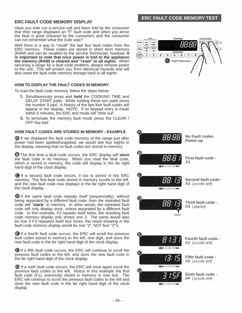
ERC FAULT CODE MEMORY TESTERC FAULT CODE MEMORY DISPLAYHave you ever run a service call and been told by the consumer that their range displayed an "F" fault code and when you arrive the fault is gone (cleared by the consumer) and the consumer can not remember what the code was?Well there is a way to "recall" the last four fault codes from the ERC memory. These codes are stored in short term memory (RAM) and can be recalled by the service Technician; however, it is important to note that once power is lost to the appliance the memory (RAM) is cleared and "reset" to all eights . When servicing a range for a fault code problem, always remove power to the unit. This will protect you from electrical hazards and will also reset the fault code memory storage back to all eights.
HOW TO DISPLAY THE FAULT CODES IN MEMORY
To read the fault code memory, follow the steps below:
If we displayed the fault code memory of the range just after power had been applied/reapplied, we would see four eights in the display, meaning that no fault codes are stored in memory.
The first time a fault code occurs, the ERC display will store the fault code in its memory. When you read the fault code, which is stored in memory, the code will display in the far right hand digit of the clock display.
If a second fault code occurs, it too is stored in the ERC memory. The first fault code stored in memory scrolls to the left, and the new fault code now displays in the far right hand digit of the clock display.
If the same fault code repeats itself (sequencially), without being separated by a different fault code, then the repeated fault code will "stack " in memory. In other words, the repeated fault code will only display once, unless separated by a different fault code. In this example, F3 repeats itself twice, the resulting fault code memory display only shows one 3. The same would also be true if F3 repeated itself four times, the result showing in the fault code memory display would be one "3", NOT four "3"'s.
If a fourth fault code occurs, the ERC will scroll the previous fault codes stored in memory to the left, one digit, and store the new fault code in the far right hand digit of the clock display.
If a fifth fault code occurs, the ERC will continue to scroll the previous fault codes to the left, and store the new fault code in the far right hand digit of the clock display.
If a sixth fault code occurs, the ERC will once again scroll the previous fault codes to the left. Notice in this example the first fault code (F1), previously stored in memory is now lost. The ERC will continue to scroll the previous fault codes to the left and store the new fault code in the far right hand digit of the clock display.
Simultaneously press and hold the COOKING TIME and DELAY START pads. While holding these two pads press the number 9 pad. A history of the last four fault codes will appear in the display. NOTE: If no keypad entry is made within 5 minutes, the ERC test mode will "time out".To terminate the memory fault mode press the CLEAR / OFF key pad
1.
2.
No Fault codesPower-up
First fault code -F1
Second fault code -F3 (scrolls left)
Third fault code - F3 (stacks)
Fourth fault code - F1 (scrolls left)
Fifth fault code - F5 (scrolls left)
Sixth fault code - FF (scrolls left)
A
B
C
D
G
F
E
scrolls left
HOW FAULT CODES ARE STORED IN MEMORY - EXAMPLE A
B
scrolls left
C
D
Stacks
scrolls left
E
scrolls left
F
scrolls left
G
TrueTemp
Convection
OVEN
BAKEPROBE
SELFCLEAN
CLEAROFF
BAKE
1 2 3 4 5 6 7 8 9 0
CONVECTIONROAST
CONVECTION
BROIL
CLOCK
START
HI LO
KITCHENTIMER OVEN
LIGHT
TOPLIGHT
COOKINGTIME
DELAYSTART
TIME CONTROLS
ON OFF

– 25 –
ERC FAILURE CODES
• Measure each sensor lead from connector block to ground. If shorted, look for pinched or cut wire insensor circuit.
• Check connector terminals - Look for deformed or corrosion on terminals. Repair or replace.• Check connector at sensor (remove sensor and carefully pull leads with connector into oven)• If all above is ok replace control.
FAILURE MEANING CORRECTIONCODE-F0--F1--F7-
Stuck key pad or transistorfailure. May mean relay isturned on.
If code cannot be cancelled, replacecontrol.
-F2-Also see
fanthermalswitches
Indicates that oven is overtemperature in one of the followingmodes within either a cooking orclean mode of operation.• Control senses oven
temperature above 630°F with
• Look for welded relay contacts. (Heatingelements on in off mode).
• Look for high resistance in the sensorcircuit due to high contact resistance(poor terminal crimp, deformed terminals,loose connection inside sensor tube) orintermittent solder joint.
• Electrical noise interference in the sensorcircuit (Ham radio, cordless phone etc.).
the door circuit in the unlock mode.• Control senses oven temperature above
930°F with the door in the door locked mode.
-F3--F4-
Open sensor (circuit) (over 2700ohms) Shorted sensor (circuit)(under 950 ohms)
Could be result of contamination onterminals, pinched harness lead, or coldsolder joint on control.
• Disconnect power to range.• Disconnect sensor connector at control.
Measure sensor resistance at controlconnector (take care not to damageterminals in block) - Should read 1100Ω atroom ambient (approx. 72°F).
-FC- Check wiring and test operation of switches.Perform resistance check.
Problem with door lock circuit suchas pinched wires between controland door lock switches.
-FF- Door motor safety switch transistorfailure
Replace control.
-F5- Loss of relay drive circuit • Press Clear/Off and reprogram control.If -F5- code reappears, replace control.
• Check sensor circuit.• Check lock circuit.
If all above check OK the F5 code can be a result of a momentary loss of power (DONOT REPLACE CONTROL AND LOCK.) Check lock circuit.
NOTE:Connections can be intermittent due to a corrosive buildup between theconnection to the terminals, or by being bent by the insertion of a probe, etc.

– 26 –
ERC ON BOARD DIAGNOSTIC TESTS
This test allows the Technician to energize various bake, broil, and convection circuits. This test will also allow you to energize the oven light and top panel light, and test key panel responses.
How To Enter And Exit The Diagnostic ModeTo perform the ERC diagnostic tests, follow the steps below:
How To Perform The TestsThe following tests allow you to quickly verify various ERC and keypad functions. Listed below are the diagnostic tests that can be performed directly from the ERC.NOTE: If anyone of the keypads is pressed and held too long the ERC may terminate the test mode, beep continuously, or display F7.
➊ CONVECTION FAN MOTOR TEST - To perform this test, press and hold the CONVECTION ROAST pad (for the fan to energize the door must be closed ). Quickly open the door an listen for the convection fan motor. As soon as you release the CONVECTON ROAST pad the fan motor will deenergize. If the fan motor did not energize, check the following: reconfirm that you have entered the test mode correctly, check power and wiring connections to the ERC, check for a bad fan motor, door switch or ERC.
➋ ENERGIZE BAKE CIRCUIT - To perform this test, press BAKE then START and listen for the bake relay to energize. CAUTION: If you hold the start pad in, you are energizing the bake element. As soon as you release the START pad the relay will deenergize. If the relay does not energize, check the following: reconfirm that you have entered the test mode correctly, check power and wiring connections to the ERC, check for an open bake element and lastly, suspect a faulty ERC.
➌ ENERGIZE BROIL CIRCUIT - To perform this test, press BROIL then START and listen for the broil relay to energize. CAUTION: if you hold the start pad in, you are energizing the broil element. As soon as you release the START pad the relay will deenergize. If the relay does not energize, check the following: reconfirm that you have entered the test mode corrrectly, check power and wiring connections to the ERC, check for an open broil element, and lastly, suspect a faulty ERC.
To initiate the ERC test mode, first remove power to the appliance for approx. 8 seconds and then reapply power.Simultaneously press and hold the COOKING TIME and DELAY START pads. While holding these two pads press the number 8 pad. The word "tESt" will appear in the ERC display. NOTE: If no keypad entry is made within 5 minutes, the ERC test mode will "time out".To terminate the ERC test mode, press the CLEAR / OFF key pad.
1.
2.
3.
ConvectionFan Motor
Test
1
TrueTemp
Convection
OVEN
BAKEPROBE
SELFCLEAN
CLEAROFF
BAKE
1 2 3 4 5 6 7 8 9 0
CONVECTIONROAST
CONVECTION
BROIL
CLOCK
START
HI LO
KITCHENTIMER OVEN
LIGHT
TOPLIGHT
COOKINGTIME
DELAYSTART
TIME CONTROLS
ON OFF
2
3
Disregard these numbers asthey have no relevance on thebroil circuit test
BakeCircuit
Test
BroilCircuit
Test

– 27 –
➍ ENERGIZE CONVECTION BAKE CIRCUIT - To perform this test press CONVECTION BAKE then START and listen for the convection bake relay to energize. CAUTION: If you hold the start pad in, you are energizing the convection element. As soon as you release the START pad the relay will de-energize. If the relay does not energize, check the following: Reconfirm that you have entered the test mode correctly, check power and wiring connections to the ERC, check for an open convection element, and lastly suspect a faulty ERC.
➎ NUMERIC KEY PADS TEST - To perform proper numeric key panel responses, press any numbered key pad and hold it in for approximately 5 seconds; the number you are pressing will show in the ERC display. If it does not, reconfirm that you have entered the test mode correctly, check wiring connections to the ERC and keypad ribbon.
➏ ENERGIZE OVEN LIGHT CIRCUIT - To perform this test press OVEN LIGHT then START and listen for the oven light relay to energize. Look through the front window of the oven door to see the light come on. As soon as you release the OVEN LIGHT pad the oven light relay will de-energize. If the relay does not energize, check the following: reconfirm that you have entered the test mode correctly, check power and wiring connections to the ERC, check for an open light bulb, and lastly, suspect a faulty ERC.
➐ ENERGIZE TOP PANEL LIGHT CIRCUIT - To perform this test, press the TOP LIGHT key pad, and watch the top fluorescent light energize. As soon as you release the TOP LIGHT pad the fluorescent light will deenergize. If the light does not energize, check the following: reconfirm that you have entered the test mode correctly, check power and wiring connections to the ERC, check for a defective bulb, starter or ballast and lastly suspect a faulty ERC.
4
5
Conv. BakeCircuit
Test
6Oven Light
CircuitTest
NumericKey pad
Test
EXAMPLE: Number 5 keypad pressed
7Top Panel
Light CircuitTest

– 28 –
COM
COM
FRONT -UNLOCK SWITCH
REAR -LOCK SWITCH
1100 Ω at Room Temp.2850 Ω at Clean Temp.
Latch circuit shown in UNLOCKED mode
DOOR LATCH MECHANISM
The latch mechanism is thermally controlled. When the SELF CLEAN cycle is selected the ERC supplies power to the lock motor, driving the motor towards the LATCHED position. When the lock motor reaches the LATCHED position, the micro-switches on the lock mechanism signal the control board to stop the motor, leaving it in the LATCHED position. When the oven temperature reaches 560˚ to 650˚ F., the ERC prevents the lock motor from being energized (DOOR LOCKED ).
When the oven sensor senses a temperature of approximately 300˚F. the ERC once again supplies power to the lock motor, driving it towards the UNLOCKED position. When the UNLOCKED position is reached, the micro-switches on the lock mechanism signal the control board to stop the motor, leaving it in the UNLOCKED position.
Rear
Front
Rear
Front
Rear
Front
Rear
Front
UNLOCKED position Moving toward LATCHEDposition
LATCHED position Moving toward UNLOCKEDposition
LOCK MOTOR CYCLE
A B
C D
ContactsClosed
ContactsOpen
ContactsOpen
ContactsOpen
➑ LOCK MOTOR CYCLE TEST - This test allows you to run the lock motor through one complete cycle of operation; testing lock motor operation, and front and rear latch switch contacts. To perform this test push and hold the SELF CLEAN key pad - make sure that the oven door is closed (light switch depressed). While depressing the SELF CLEAN pad, the lock motor will run through a complete cycle. Watch the ERC display closely as it will change based on the location of the motor and logic switch contact positions (open or closed).
Illustrations 8a, 8b, 8c, 8d, & 8e show the sequence of events that will occur during the complete lock motor cycle. Notice the numbers shown in the left side of each display represent the position of the lock motor as well as the logic switch contact positions (open or closed). While performing the lock motor cycle test, the words LOCKED DOOR will flash in the ERC display during 8b and 8d.
UNLOCKED POSITIONRear switch contacts openFront switch contacts closed
Moving toward LATCHEDPOSITIONRear switch contacts openFront switch contacts open
LATCHED POSITIONRear switch contacts closedFront switch contacts open
Moving toward UNLOCKEDPOSITIONRear switch contacts openFront switch contacts open
Return to UNLOCKEDPOSITIONRear switch contacts openFront contacts closed
ContactsOpen
ContactsOpen
ContactsOpen
ContactsClosed
8
8
a
b
8c
8d
8e
MEAT PROBE
W
12345678
W Y OBU
OVEN TEMPSENSOR
L
COM MDL
LOCKMOTOR DOOR
SWITCH
N
NC
CNO
ERCK1 Relay
Lock motor circuit shown inRUN MODE

– 29 –
VISIONTM RANGE W/ERC V TRUETEMP
TM
375˚ 380˚ 395˚ 365˚ 370˚ 390˚ 360˚ 385˚ 355˚
PREVIOUS MODELS
THERMOSTATSETTING
THERMOSTAT CYCLINGTemperatures shown in degrees F.
GE TRUETEMP™, THE MOST ACCURATE OVEN IN AMERICA!The guesswork is gone. The temperamental oven is a thing of the past. GE's exclusive TrueTemp™ system manages and maintains the oven temperature you select. It's more accurate than any other leading brand. The SmartLogic™ electronic control, with a platinum sensor, constantly monitors the oven's performance to ensure more precise temperature management. Even if you open the door when the oven is on, SmartLogic™ senses variations in temperature and responds to regain the selected setting.
* Among leading manufactures' brands
True
Tem
p™
XL44™ RANGES w/ERC V TRUE TEMP
PREVIOUS MODELS
ERC V TrueTemp™, with on board SmartLogic™, man-ages and maintains the oven temperature you select. ERC controls with TrueTemp™, SmartLogic™ can be identi-fied by the words TrueTemp, located just above the ERC display, on the front of the control panel.
SmartLogic™ Electronic Control
with Platinum Oven Sensor
Monitors and maintains oven temperature. Senses sudden, significant heat loss and respondswith extra power.
The Most AccurateOven In America!*
*Among leading brands
xceptional cooking
performance does not come about by chance. It requires advanced technology and innovative design. GE proudly introduces the TrueTemp™ System, which delivers consistently even oven temperature for exceptional cooking results -- making it the industry leader.
E
400 395 390 385 380 375 370 365 360 355
TE
MP
ER
ATU
RE
- D
EG
RE
ES
F.
THERMOSTAT CYCLINGERC V w/ TRUETEMP™ VS PREVIOUS GE MODELS
TIMEBurner ON Burner ONBurner OFF Burner OFF Burner ON
TrueTemp™Oven Cycling

– 30 –
SURF IND LIGHT
SURF IND LIGHT
MEAT PROBE
OVEN TEMP1100 ROOM TEMP2850 CLEAN TEMP
W W Y OBU
12345678
SURF ELEMH2H1
PLI
2 5
3
4
L2
N
HOT IND LIGHTS
RELAYCONTACT
MADEBAKE
BROIL
CLEAN
CONV BAKE
CONV ROAST
K1
WATTAGE RESISTANCE1500W RR
1800W LR
38.4 2500W RF
(BOTH ELEM)1000W RF
(INNER ELEM)2600W LF
(BOTH ELEM)800W LF
(INNER ELEM)
23.0
57.6
22.2
72.0
32.0
SURFACE ELEMENTS
Q2 K2 - BRERC
K4 - CV K3 - BA
RR-BR•TR
RF-GY
LF-GY•TR
LR-O•TR
02
Q1
K2K3K4
COM NDL CONV BA BR LI LIGND
N
N
NBAL LAST
FLO LIGHT
OV LIGHT
DOOR JAMB SW
LOCK MOTOR
BROIL ELEM
BAKE ELEM
CONV ELEM
N
STARTER
CFOVENLIGHT
CONVFANM
M
SURFLIGHT
K1
SURF ELEM
SURF ELEM
PROTECTOR
PROTECTOR DUAL ELEM CONT
DUAL ELEM CONT
LOCK SW #2
LOCK SW #1
UNLOCK
LOCK
BU
SURF CONTRR-BR & LR-O
RF-BU•TR & LF-Y•TR
PR
“LI” BLACK “L2” RED
SURF CONT
*** **
**
****
**
*** ***
JB960WBJB960ABJB960BB
LF (BRIDGE) & RF (OUTER)
SCHEMATIC
ERC

– 31 –
STARTER
FLO LIGHTSURFLIGHT
ERC BOARD
L1 N
L1
FLOURECENT LIGHT CIRCUIT
L2
BRBROIL
ELEMENT
ERC BOARD
L1
Relay Energized
L-1
BROIL CIRCUIT
K2 RELAY
L2
BABAKE
ELEMENT
ERC BOARD
L1
Relay Energized
L-1
BAKE CIRCUIT
K3 RELAY
L2
BRBROIL
ELEMENT
ERC BOARD
L1
Relay Energized
L-1
CONV ROAST CIRCUIT
K2 RELAY
COM
COM
FRONT -UNLOCK SWITCH
REAR -LOCK SWITCH
1100Ω at Room Temp.2850Ω at Clean Temp.
Latch circuit shown in UNLOCKED mode
MEAT PROBE
W
12345678
W Y OBU
OVEN TEMPSENSOR
L
COM MDL
LOCKMOTOR DOOR
SWITCH
N
NC
CNO
ERCK1 Relay
Lock motor circuit shown inRUN MODE
BAL LAST
Q1
OVEN LIGHT
ERC BOARD
L1 N
L1
OVEN LIGHTERC TOUCH PAD
OVENLIGHT
OVEN LIGHT
L1 NOVEN LIGHTDOOR OPEN
DOORSWITCH
CONV FANMOTORCFL1
Q2
M
DOORSWITCH
19.3 Ω
15.0 Ω
15.0 Ω
15.0 Ω
L2
CONVCONVECTION
ELEMENT
ERC BOARD
L1
Relay Energized
L-1
CONV BAKE CIRCUIT
K4 RELAY
CONV FANMOTORCFL1
Q2
M
DOORSWITCH
15.0 Ω
23.0 Ω
23.5 Ω
STRIP CIRCUITSJB960WBJB960ABJB960BB

– 32 –
SURF IND LIGHT
LF SURF ELEM
SURF CONT
LI L2
SURF CONT
N
THERMALLIMITER SW.
52
HI88
HI
664
2LO LO 2
4
BRIDGEBURNER
OFF
FRONTBURNER
FRONT
LEFT FRONT SURFACEUNIT ONLY
3
4BRIDGE ELEM
L2
5 N
2 3
L1L1
H1
TOP
4P
L2
H2
N
4
32
GRND
5P
H2
H1 GRND
CYCLINGCONTACT
10.45 KΩ
VOLTAGE SENSITIVE
LF S
URFA
CE E
LEM
ENT
BRID
GE E
LEM
ENT
SURFACE ELEMENT STRIP CIRCUITS
MODELS:JB960WBJB960ABJB960BB
31.0 Ω
70.0 Ω
SURF IND LIGHT
LF SURF ELEM
LI L2
SURF CONTTHERMAL
LIMITER SW.
52
L2
5 N
2 3
L1L1
H1
TOP
4P
L2
H2
N
4
32
GRND
5P
H2
H1 GRND
CYCLINGCONTACT
10.45 KΩ
VOLTAGE SENSITIVE
HI88
HI
FRONTBURNER
BRIDGEBURNER
664
2LO LO 2
4
OFF
FRONT
LEFT FRONT SURFACEUNIT + BRIDGE
3
4BRIDGE ELEM
LF S
URFA
CE E
LEM
ENT
BRID
GE E
LEM
ENT
SURF CONTN
31.0 Ω
70.0 Ω
SURF IND LIGHT
LR SURF ELEM
SURF CONT
LI L2
SURF CONT
H2 L2
THERMALLIMITER SW.
H1
PLI
VOLTAGE SENSITIVE
H1
P
H2
L1 L2
TOP
REAR
LEFT REARSURFACE UNIT
1800 W32.0 Ω
L1
P
N
PILOT
L2 H2
H1
LRSURFACE
UNIT15.59 KΩ

– 33 –
SURFACE ELEMENT STRIP CIRCUITS
SURF IND LIGHT
RR SURF ELEM
SURF CONT
LI L2
SURF CONT
H2 L2
THERMALLIMITER SW.
H1
PLI
WM
REAR
RIGHT REARSURFACE UNIT
H1
P
H2
L2L1
CURRENTSENSITIVE
L2L2
N
PILOT
P
H1
H2
L1L1
RRSURFACE
UNIT
< 1 Ω
1500 W38.4 Ω
HI88
HI
6
64
2
LOLO 2
4
SMALLBURNER
LARGEBURNER
OFF
WM
SURF IND LIGHT
INNER ELEM
SURF CONT
LI L2
SURF CONT
N
THERMALLIMITER SW.
52
L2
5 N
2 3
L1L1
H1
TOP
4P
L2
H2
N
4
32
GRND
5P
H2
H1 GRND
CYCLINGCONTACT
10.45 KΩ
VOLTAGE SENSITIVE
RF INNER SURFACEUNIT ONLY
3
4OUTER ELEM
INNE
R EL
EMEN
T
OUTE
R EL
EMEN
T
FRONT
37.0 Ω
55.0 Ω
SURF IND LIGHT
INNER ELEM
LI L2
SURF CONTTHERMAL
LIMITER SW.
52
L2
5 N
2 3
L1L1
H1
TOP
4P
L2
H2
N
4
32
GRND
5P
H2
H1 GRND
CYCLINGCONTACT
10.45 KΩ
VOLTAGE SENSITIVE
RF INNER & OUTERSURFACE UNITS
3
4OUTER ELEM
INNE
R EL
EMEN
T
OUTE
R EL
EMEN
T
HI88
HI
6
64
2
LOLO 2
4
SMALLBURNER
LARGEBURNER
OFF
WM
FRONT
SURF CONTN
37.0 Ω
55.0 Ω
MODELS:JB960WBJB960ABJB960BB
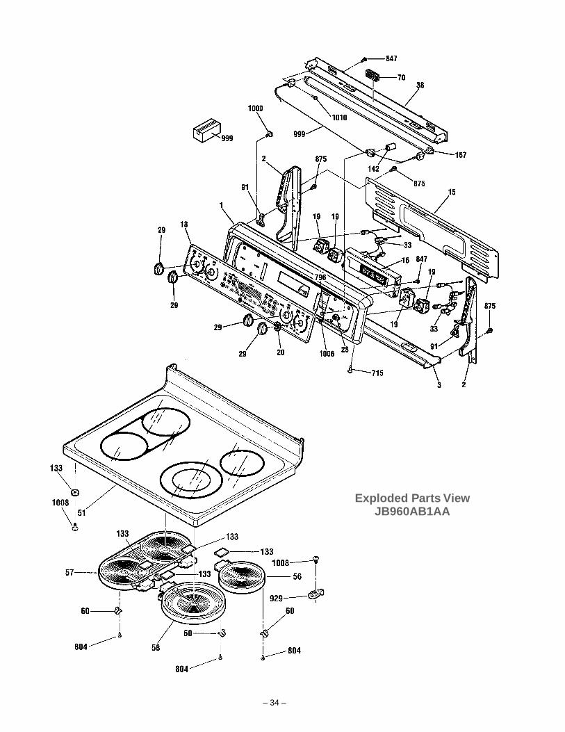
– 34 –
Exploded Parts ViewJB960AB1AA

– 35 –
Exploded Parts ViewJB960AB1AA
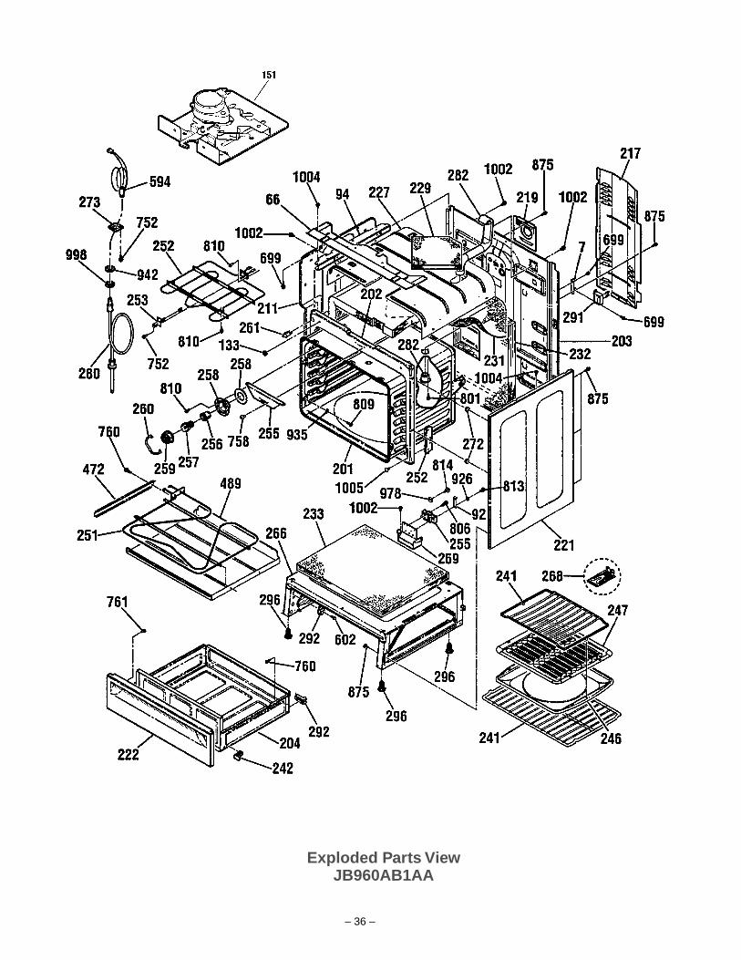
– 36 –
Exploded Parts ViewJB960AB1AA
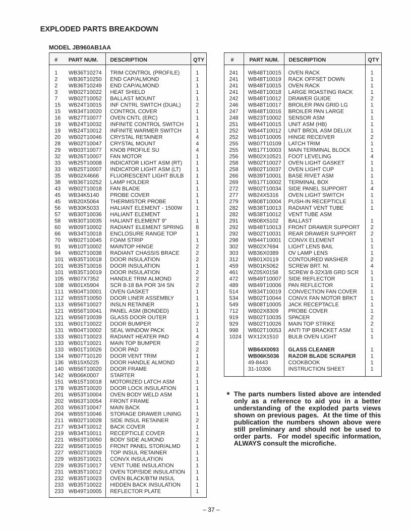
– 37 –
# PART NUM. DESCRIPTION QTY
1 WB36T10274 TRIM CONTROL (PROFILE) 12 WB36T10250 END CAP/ALMOND 12 WB36T10249 END CAP/ALMOND 13 WB02T10022 HEAT SHIELD 17 WB02T10052 BALLAST MOUNT 115 WB24T10015 INF CNTRL SWITCH (DUAL) 215 WB34T10020 CONTROL COVER 116 WB27T10077 OVEN CNTL (ERC) 119 WB24T10032 INFINITE CONTROL SWITCH 119 WB24T10012 INFINITE WARMER SWITCH 120 WB02T10046 CRYSTAL RETAINER 428 WB02T10047 CRYSTAL MOUNT 429 WB03T10077 KNOB PROFILE SU 432 WB26T10007 FAN MOTOR 133 WB25T10008 INDICATOR LIGHT ASM (RT) 133 WB25T10007 INDICATOR LIGHT ASM (LT) 135 WB02X4666 FLUORESCENT LIGHT BULB 138 WB36T10252 LAMP HOLDER 143 WB02T10018 FAN BLADE 145 WB34K5140 PROBE COVER 145 WB20X5064 THERMISTOR PROBE 156 WB30K5033 HALIANT ELEMENT - 1500W 157 WB30T10036 HALIANT ELEMENT 158 WB30T10035 HALIANT ELEMENT 9" 160 WB09T10002 RADIANT ELEMENT SPRING 866 WB34T10018 ENCLOSURE RANGE TOP 170 WB02T10045 FOAM STRIP 191 WB10T10002 MAINTOP HINGE 294 WB02T10038 RADIANT CHASSIS BRACE 2101 WB35T10018 DOOR INSULATION 2101 WB35T10016 DOOR INSULATION 1101 WB35T10019 DOOR INSULATION 2105 WB07X7352 HANDLE TRIM ALMOND 2108 WB01X5904 SCR 8-18 BA POR 3/4 SN 2111 WB04T10001 OVEN GASKET 1112 WB55T10050 DOOR LINER ASSEMBLY 1113 WB56T10027 INSLN RETAINER 1121 WB56T10041 PANEL ASM (BONDED) 1121 WB56T10039 GLASS DOOR OUTER 1131 WB01T10022 DOOR BUMPER 2131 WB04T10002 SEAL WINDOW PACK 1133 WB01T10023 RADIANT HEATER PAD 4133 WB01T10021 MAIN TOP BUMPER 2133 WB01T10026 DOOR PAD 2134 WB07T10120 DOOR VENT TRIM 1136 WB15X5225 DOOR HANDLE ALMOND 1140 WB56T10020 DOOR FRAME 2142 WB06K0007 STARTER 1151 WB15T10018 MOTORIZED LATCH ASM 1178 WB35T10020 DOOR LOCK INSULATION 1201 WB53T10004 OVEN BODY WELD ASM 1202 WB63T10054 FRONT FRAME 1203 WB63T10047 MAIN BACK 1204 WB55T10046 STORAGE DRAWER LINING 1211 WB02T10028 SIDE INSUL RETAINER 2217 WB34T10012 BACK COVER 1219 WB34T10011 RECEPTICLE COVER 1221 WB63T10050 BODY SIDE ALMOND 2222 WB56T10015 FRONT PANEL STOR/ALMD 1227 WB02T10029 TOP INSUL RETAINER 1229 WB35T10021 CONVX INSULATION 1229 WB35T10017 VENT TUBE INSULATION 1231 WB35T10012 OVEN TOP/SIDE INSULATION 1232 WB35T10023 OVEN BLACK/BTM INSUL 1233 WB35T10022 HIDDEN BACK INSULATION 1233 WB49T10005 REFLECTOR PLATE 1
# PART NUM. DESCRIPTION QTY
241 WB48T10015 OVEN RACK 1241 WB48T10019 RACK OFFSET DOWN 1241 WB48T10015 OVEN RACK 1241 WB48T10018 LARGE ROASTING RACK 1242 WB48T10012 DRAWER GUIDE 2246 WB48T10017 BROILER PAN GRID LG 1247 WB48T10016 BROILER PAN LARGE 1248 WB23T10002 SENSOR ASM 1251 WB44T10015 UNIT ASM (HB) 1252 WB44T10012 UNIT BROIL ASM DELUX 1252 WB10T10005 HINGE RECEIVER 2255 WB07T10109 LATCH TRIM 1255 WB17T10003 MAIN TERMINAL BLOCK 1256 WB02X10521 FOOT LEVELING 4258 WB02T10027 OVEN LIGHT GASKET 1258 WB02T10037 OVEN LIGHT CUP 1266 WB39T10001 BASE RIVET ASM 1269 WB17T10002 TERMINAL BOX 1272 WB02T10034 SIDE PANEL SUPPORT 4277 WB24X5316 OVEN LIGHT SWITCH 1279 WB08T10004 PUSH-IN RECEPTICLE 1282 WB38T10013 RADIANT VENT TUBE 1282 WB38T10012 VENT TUBE ASM291 WB08X5102 BALLAST 1292 WB48T10013 FRONT DRAWER SUPPORT 2292 WB02T10031 REAR DRAWER SUPPORT 2298 WB44T10001 CONVX ELEMENT 1302 WB02X7694 LIGHT LENS BAIL 1303 WB36X0389 OV LAMP LENS 1312 WB01X0119 CONTOURED WASHER 2459 WB01K5062 SCREW BRT. NI. 4461 WZ05X0158 SCREW 8-32X3/8 GRD SCR 1472 WB49T10007 SIDE REFLECTOR 1489 WB49T10006 PAN REFLECTOR 1514 WB34T10019 CONVECTION FAN COVER 1534 WB02T10044 CONVX FAN MOTOR BRKT 1549 WB08T10005 JACK RECEPTACLE 1712 WB02X8309 PROBE COVER 1919 WB02T10035 SPACER 2929 WB02T10026 MAIN TOP STRIKE 2998 WB02T10053 ANTI TIP BRACKET ASM 11024 WX12X1510 BULB OVEN LIGHT 1
WB64X0093 GLASS CLEANER 1WB06K5036 RAZOR BLADE SCRAPER 149-8443 COOKBOOK 131-10306 INSTRUCTION SHEET 1
MODEL JB960AB1AA
EXPLODED PARTS BREAKDOWN
The parts numbers listed above are intended only as a reference to aid you in a better understanding of the exploded parts views shown on previous pages. At the time of this publication the numbers shown above were still preliminary and should not be used to order parts. For model specific information, ALWAYS consult the microfiche.
*