technical project presentation template
TRANSCRIPT
Hydrogen Power System for Remote Applications
Curt RobbinsDesert Research Institute
UNLV Energy SymposiumLas Vegas, NV
August 16th, 2007
2
Overview
• Project description and objectives• System description• Field site testing• Results to date• Current Work
3
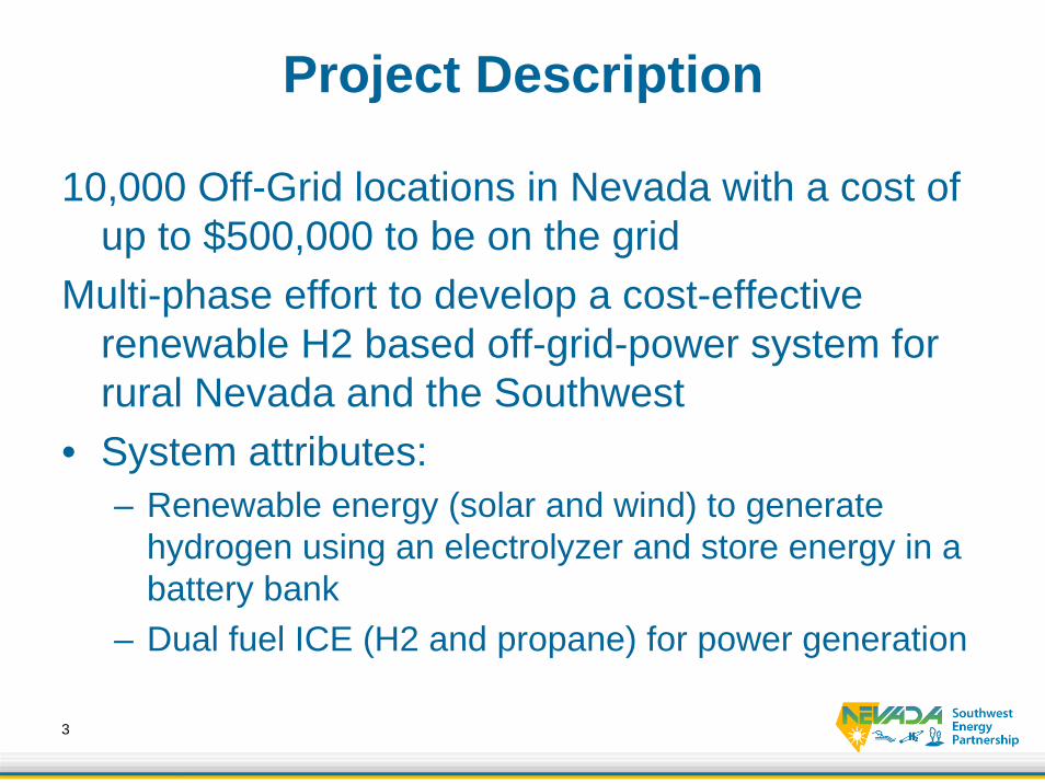
Project Description
10,000 Off-Grid locations in Nevada with a cost of up to $500,000 to be on the grid
Multi-phase effort to develop a cost-effective renewable H2 based off-grid-power system for rural Nevada and the Southwest
• System attributes: – Renewable energy (solar and wind) to generate
hydrogen using an electrolyzer and store energy in a battery bank
– Dual fuel ICE (H2 and propane) for power generation
4
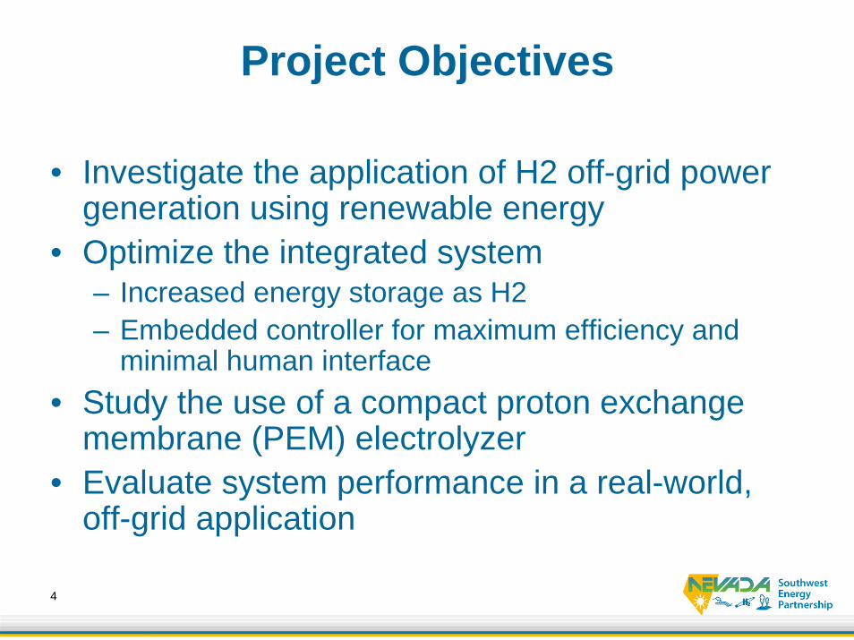
Project Objectives
• Investigate the application of H2 off-grid power generation using renewable energy
• Optimize the integrated system– Increased energy storage as H2– Embedded controller for maximum efficiency and
minimal human interface• Study the use of a compact proton exchange
membrane (PEM) electrolyzer• Evaluate system performance in a real-world,
off-grid application
5
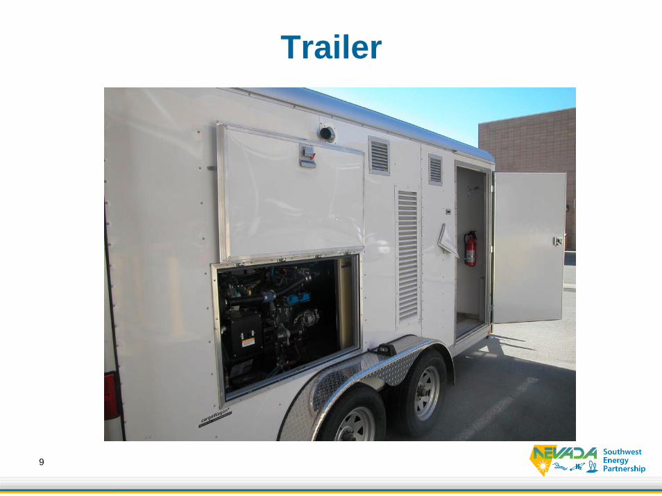
Trailer Components
• 12 Foot Wells Cargo enclosed trailer• Outback Power Systems 48 VDC/120VAC dual
inverter unit• Twelve 12VDC Gelled Electrolyte Batteries
providing 1.3 kWhr of stored energy• 600 cc/min 200 PSI PEM Electrolyzer• 4 110 ft^3 storage tanks holding .2 kg of
Hydrogen• Converted Lister Petter 2 cylinder, 4 stroke
engine and 1800 rpm 3 kWe generator
6
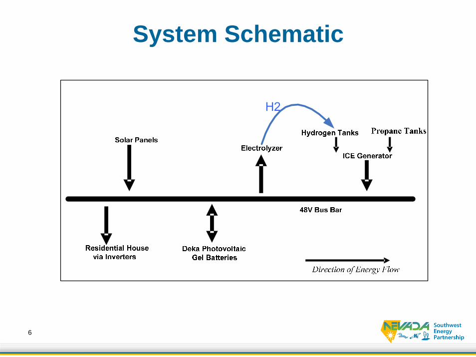
System Schematic
7
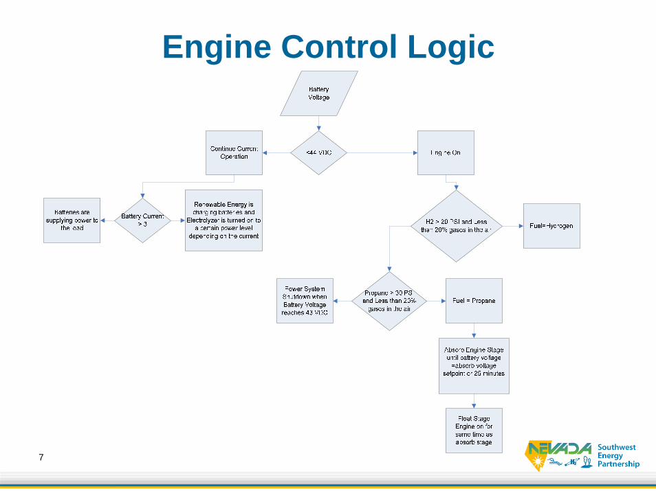
Engine Control Logic
8
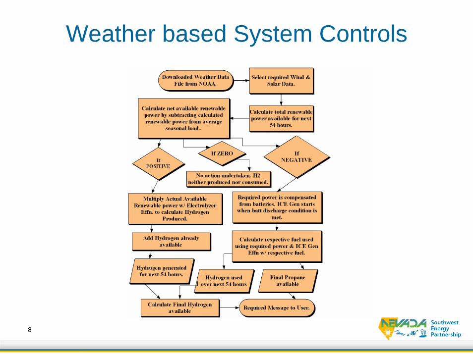
Weather based System Controls
9
Trailer
10
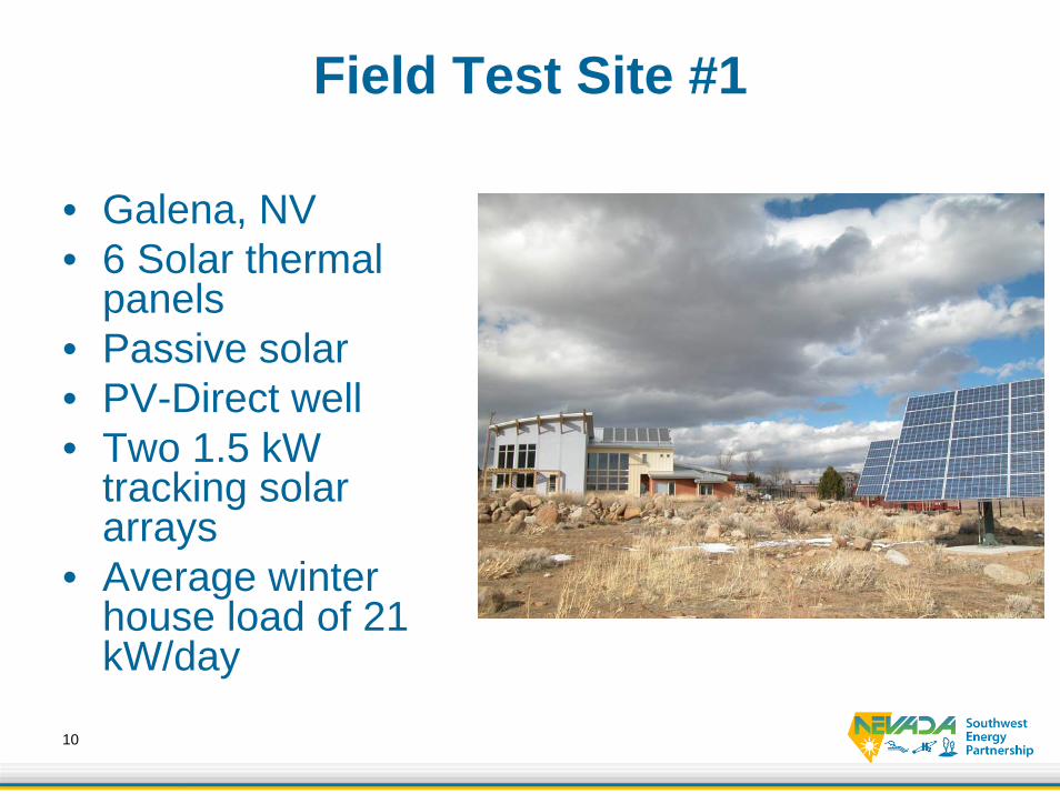
Field Test Site #1
• Galena, NV• 6 Solar thermal
panels• Passive solar• PV-Direct well• Two 1.5 kW
tracking solar arrays
• Average winter house load of 21 kW/day
11
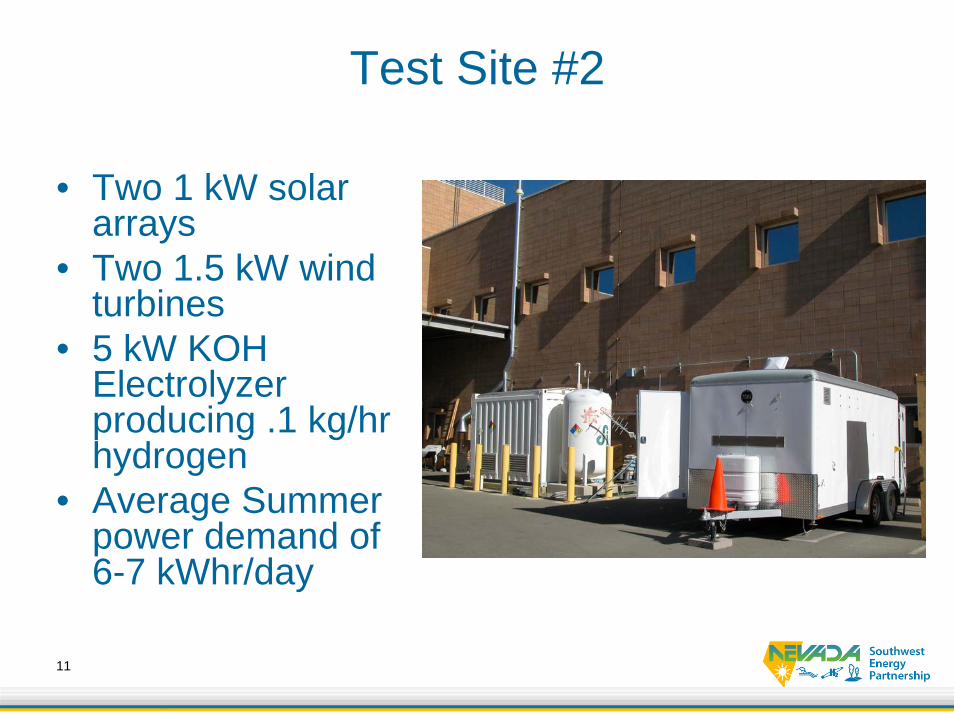
Test Site #2
• Two 1 kW solar arrays
• Two 1.5 kW wind turbines
• 5 kW KOH Electrolyzer producing .1 kg/hr hydrogen
• Average Summer power demand of 6-7 kWhr/day
12
Test Site #1 Operation
• Over 30 days of operation at test site from February into March
• One 1.5 kW solar array available for power system
• Limited electrolyzer capacity
13
Test Site #1 Results
• 1.5 kWe rated solar array observed up to 1.3 kWe
• 6 engine cycles per day to meet the winter load demand
• 40-90 minute engine cycles• 2-2.5 kg of Hydrogen necessary• Sufficient data for system evaluation
14
Upgrades for test site #2
• Engine– Retuned
• Including spark timing maps– Removed turbocharger
• Better H2 production control• Convert DRI Renewable to 48 VDC• Appropriate Load Profile• Simplified Software program
15
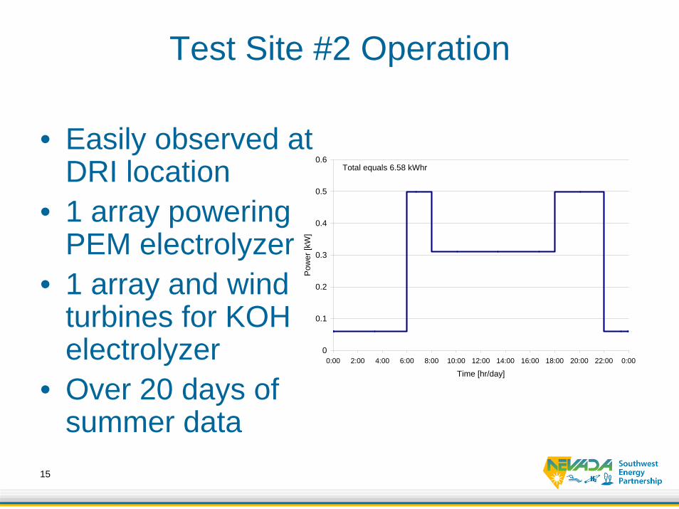
Test Site #2 Operation
• Easily observed at DRI location
• 1 array powering PEM electrolyzer
• 1 array and wind turbines for KOH electrolyzer
• Over 20 days of summer data
0
0.1
0.2
0.3
0.4
0.5
0.6
0:00 2:00 4:00 6:00 8:00 10:00 12:00 14:00 16:00 18:00 20:00 22:00 0:00
Time [hr/day]
Pow
er [k
W]
Total equals 6.58 kWhr
16
Test Site #2 Results
• PV array producing over 700 Watts continuously
• 2 Engine cycles per day at 50 minutes and .32 kg per cycle
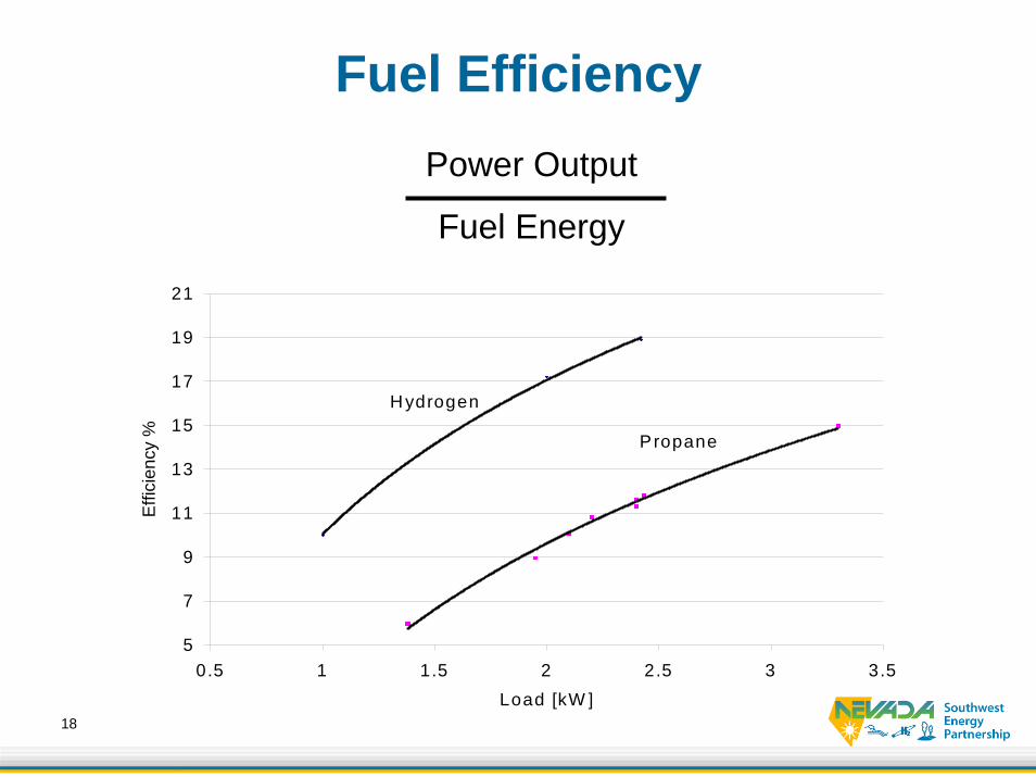
• Engine efficiency normal for engine size– 11-18% on hydrogen
• PEM electrolyzer produced up to 560 cc/min drawing 500 W
17
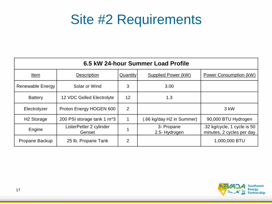
Site #2 Requirements
Item Description Quantity Supplied Power (kW) Power Consumption (kW)
Renewable Energy Solar or Wind 3 3.00
Battery 12 VDC Gelled Electrolyte 12 1.3
Electrolyzer Proton Energy HOGEN 600 2 3 kW
H2 Storage 200 PSI storage tank 1 m^3 1 (.66 kg/day H2 in Summer) 90,000 BTU Hydrogen
Engine ListerPetter 2 cylinder Genset 1 3- Propane
2.5- Hydrogen.32 kg/cycle, 1 cycle is 50 minutes, 2 cycles per day
Propane Backup 25 lb. Propane Tank 2 1,000,000 BTU
6.5 kW 24-hour Summer Load Profile
18
Fuel EfficiencyPower Output
Fuel Energy
5
7
9
11
13
15
17
19
21
0.5 1 1.5 2 2.5 3 3.5Load [kW ]
Effi
cien
cy %
H ydrogen
Propane
19
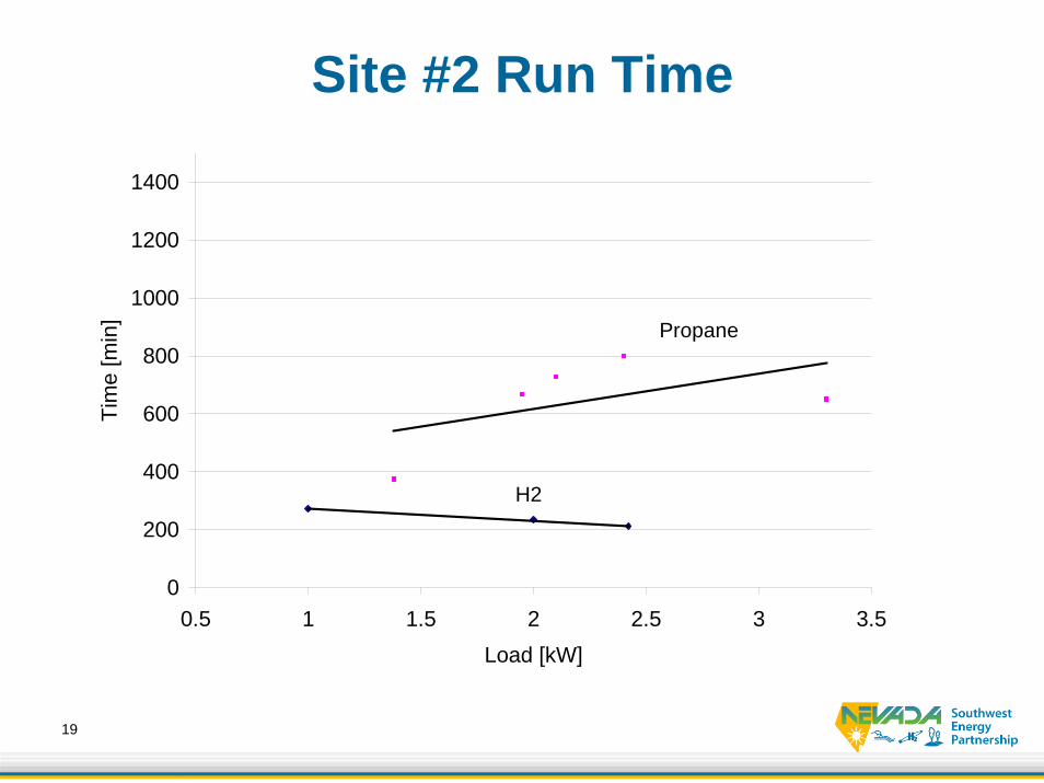
Site #2 Run Time
0
200
400
600
800
1000
1200
1400
0.5 1 1.5 2 2.5 3 3.5Load [kW]
Tim
e [m
in]
H2
Propane
20
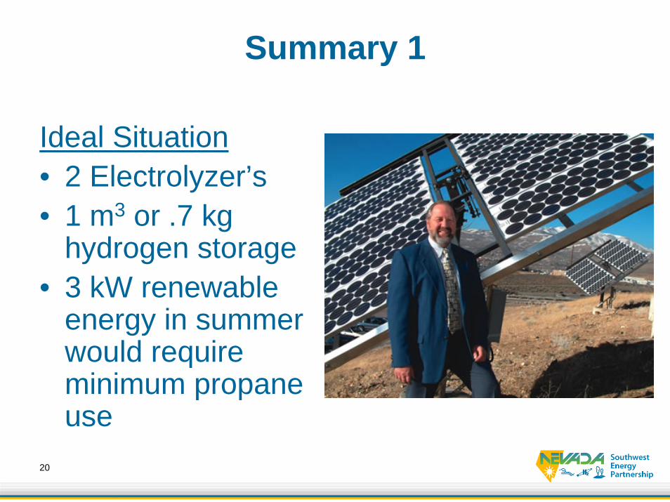
Summary 1
Ideal Situation• 2 Electrolyzer’s• 1 m3 or .7 kg
hydrogen storage• 3 kW renewable
energy in summer would require minimum propane use
21
Summary 2
• Developed and tested mobile renewable energy power system
• Unique aspects include hydrogen production, dual fuel ICE, mobile unit
• Limitations of electrolyzer and engine design• Current work includes more control over
different fuels in ICE, Maximizing engine performance, more efficient system control, ultra capacitors, and hydrogen production/storage options

22
Questions