technical note how to setup mvi56-pdpmv1
TRANSCRIPT
Where Automation Connects.
ProSoft Technology www.prosoft-technology.com
Worldwide Sales and Technical Support network
Locations in North America, Latin America, Europe / Middle-East / Africa, Asia / Pacific
Author: Jerome Prat Date: Feb-09
Technical Note
TN2009-01D-A4-2.0
How to Setup MVI56-PDPMV1
Using Add-On Instruction and CIPconnectTM
Introduction
The goal of this technical note is to allow any user to successfully achieve the complete
MVI56-PDPMV1 setup.
When the user will have followed the procedure, the module will be up and running.
Page 2 of 44 TN2009-01D-A4-2.0
Technical Note
How to Setup MVI56-PDPMV1Using Add-On Instruction and CIPconnectTM
Author: Jerome Prat Date: Feb-09
Table of contents
Introduction .............................................................................. 1
Architecture .............................................................................. 3
Procedure ................................................................................. 4
A. Setup of the MVI56-PDPMV1 ............................................................... 4
A.1. Step 1: Using RSLogix 5000 V16 .................................................. 4
A.1.1. Creating new project ........................................................................................................... 5
A.1.2. Inserting MVI56-PDPMV1 in I/O configuration ................................................................ 7
A.1.3. Inserting the MVI56-PDPMV1 program ........................................................................... 10
A.1.4. Adapting the ladder logic to the application ................................................................... 13
A.1.5. Verifying and downloading ladder logic .......................................................................... 14
A.2. Step 2: Using ProSoft Configuration Builder ................................. 17
A.2.1. General module configuration .......................................................................................... 18
A.2.2. PROFIBUS configuration .................................................................................................... 21
A.2.3. Download the configuration to the module .................................................................... 26
A.3. Step 3: Verifying communication ................................................ 29
A.3.1. On PROFIBUS using the ProSoft Configuration Builder ................................................ 29
A.3.2. Starting MVI56-PDPMV1 communication ........................................................................ 32
B. APPENDIX ....................................................................................... 35
B.1. Appendix A – Importing GSD files ............................................... 35
B.2. Appendix B – Changing PROFIBUS slave address .......................... 38
B.3. Appendix C – Configuring RSLinx ................................................ 40
Page 3 of 44 TN2009-01D-A4-2.0
Technical Note
How to Setup MVI56-PDPMV1Using Add-On Instruction and CIPconnectTM
Author: Jerome Prat Date: Feb-09
Architecture
The following material was used to prepare this technical note:
1. Rockwell Automation:
• 1756-A4
• 1756-PA72 • 1756-1756-L61 V16
• 1756-ENBT 2. ProSoft Technology:
• MVI56-PDPMV1 V1.28
The following software were used to prepare this technical note: 1. Rockwell Automation:
• RSLogix V16 • RSLinx Classic V2.54
2. ProSoft Technology:
• ProSoft Configuration Builder V2.1.1.9
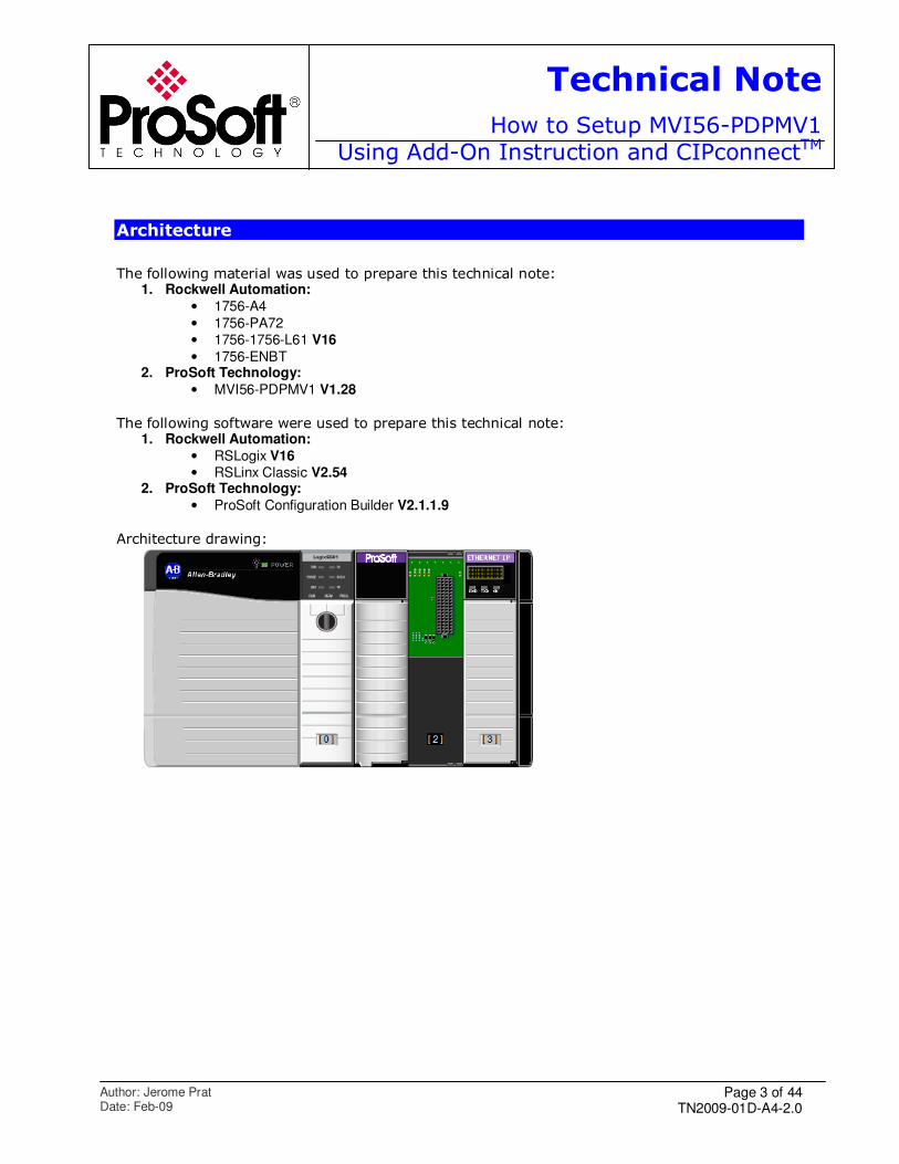
Architecture drawing:
Page 4 of 44 TN2009-01D-A4-2.0
Technical Note
How to Setup MVI56-PDPMV1Using Add-On Instruction and CIPconnectTM
Author: Jerome Prat Date: Feb-09
Procedure
Below is the step by step procedure to establish communication between a ControlLogix and a
PROFIBUS network:
A. Setup of the MVI56-PDPMV1
A.1. Step 1: Using RSLogix 5000 V16
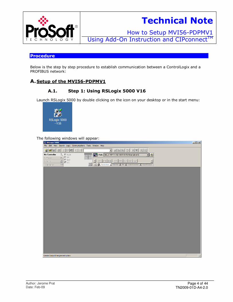
Launch RSLogix 5000 by double clicking on the icon on your desktop or in the start menu:
The following windows will appear:
Page 5 of 44 TN2009-01D-A4-2.0
Technical Note
How to Setup MVI56-PDPMV1Using Add-On Instruction and CIPconnectTM
Author: Jerome Prat Date: Feb-09
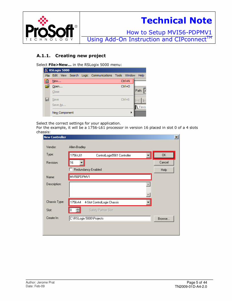
A.1.1. Creating new project
Select File>New... in the RSLogix 5000 menu:
Select the correct settings for your application. For the example, it will be a 1756-L61 processor in version 16 placed in slot 0 of a 4 slots
chassis:
Page 6 of 44 TN2009-01D-A4-2.0
Technical Note
How to Setup MVI56-PDPMV1Using Add-On Instruction and CIPconnectTM
Author: Jerome Prat Date: Feb-09
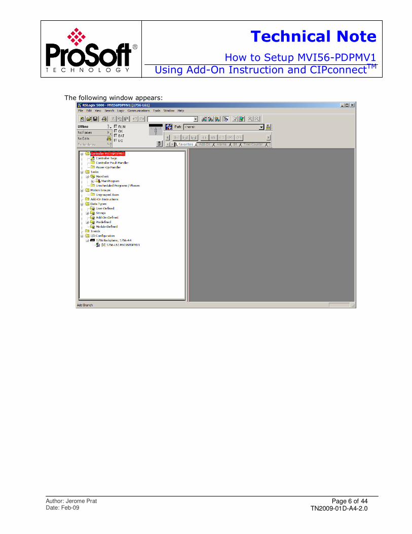
The following window appears:
Page 7 of 44 TN2009-01D-A4-2.0
Technical Note
How to Setup MVI56-PDPMV1Using Add-On Instruction and CIPconnectTM
Author: Jerome Prat Date: Feb-09
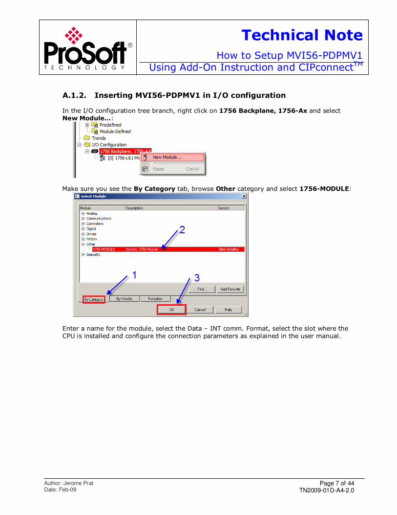
A.1.2. Inserting MVI56-PDPMV1 in I/O configuration
In the I/O configuration tree branch, right click on 1756 Backplane, 1756-Ax and select
New Module...:
Make sure you see the By Category tab, browse Other category and select 1756-MODULE:
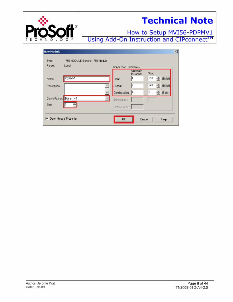
Enter a name for the module, select the Data – INT comm. Format, select the slot where the
CPU is installed and configure the connection parameters as explained in the user manual.
Page 8 of 44 TN2009-01D-A4-2.0
Technical Note
How to Setup MVI56-PDPMV1Using Add-On Instruction and CIPconnectTM
Author: Jerome Prat Date: Feb-09
Page 9 of 44 TN2009-01D-A4-2.0
Technical Note
How to Setup MVI56-PDPMV1Using Add-On Instruction and CIPconnectTM
Author: Jerome Prat Date: Feb-09
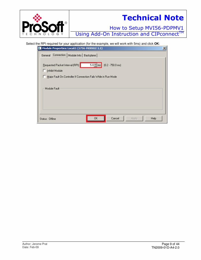
Select the RPI required for your application (for the example, we will work with 5ms) and click OK:
Page 10 of 44 TN2009-01D-A4-2.0
Technical Note
How to Setup MVI56-PDPMV1Using Add-On Instruction and CIPconnectTM
Author: Jerome Prat Date: Feb-09
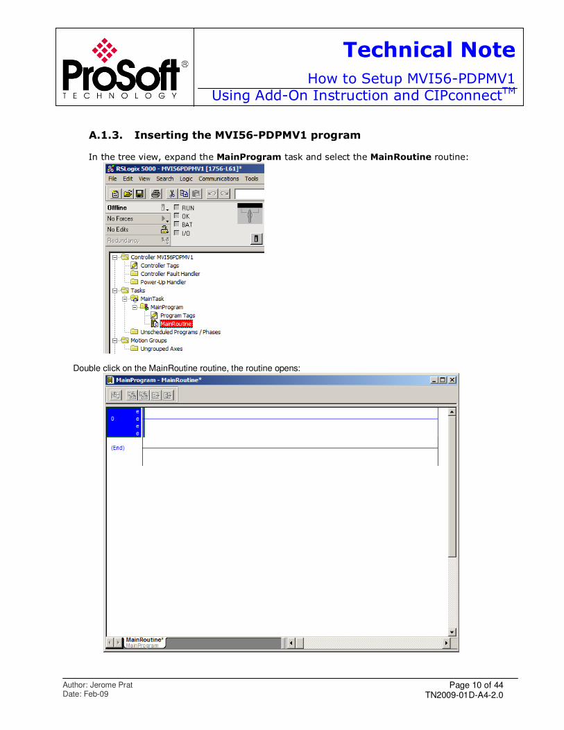
A.1.3. Inserting the MVI56-PDPMV1 program
In the tree view, expand the MainProgram task and select the MainRoutine routine:
Double click on the MainRoutine routine, the routine opens:
Page 11 of 44 TN2009-01D-A4-2.0
Technical Note
How to Setup MVI56-PDPMV1Using Add-On Instruction and CIPconnectTM
Author: Jerome Prat Date: Feb-09
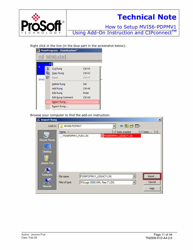
Right click in the line (in the blue part in the screenshot below):
Browse your computer to find the add-on instruction:
Page 12 of 44 TN2009-01D-A4-2.0
Technical Note
How to Setup MVI56-PDPMV1Using Add-On Instruction and CIPconnectTM
Author: Jerome Prat Date: Feb-09
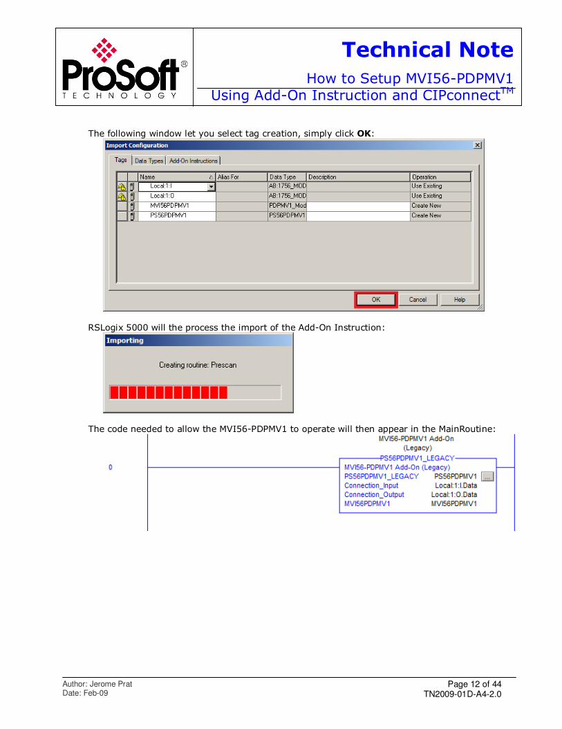
The following window let you select tag creation, simply click OK:
RSLogix 5000 will the process the import of the Add-On Instruction:
The code needed to allow the MVI56-PDPMV1 to operate will then appear in the MainRoutine:
Page 13 of 44 TN2009-01D-A4-2.0
Technical Note
How to Setup MVI56-PDPMV1Using Add-On Instruction and CIPconnectTM
Author: Jerome Prat Date: Feb-09
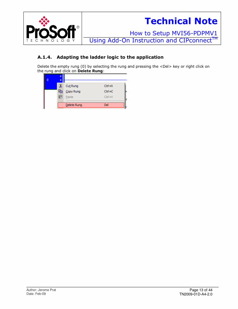
A.1.4. Adapting the ladder logic to the application
Delete the empty rung (0) by selecting the rung and pressing the <Del> key or right click on
the rung and click on Delete Rung:
Page 14 of 44 TN2009-01D-A4-2.0
Technical Note
How to Setup MVI56-PDPMV1Using Add-On Instruction and CIPconnectTM
Author: Jerome Prat Date: Feb-09
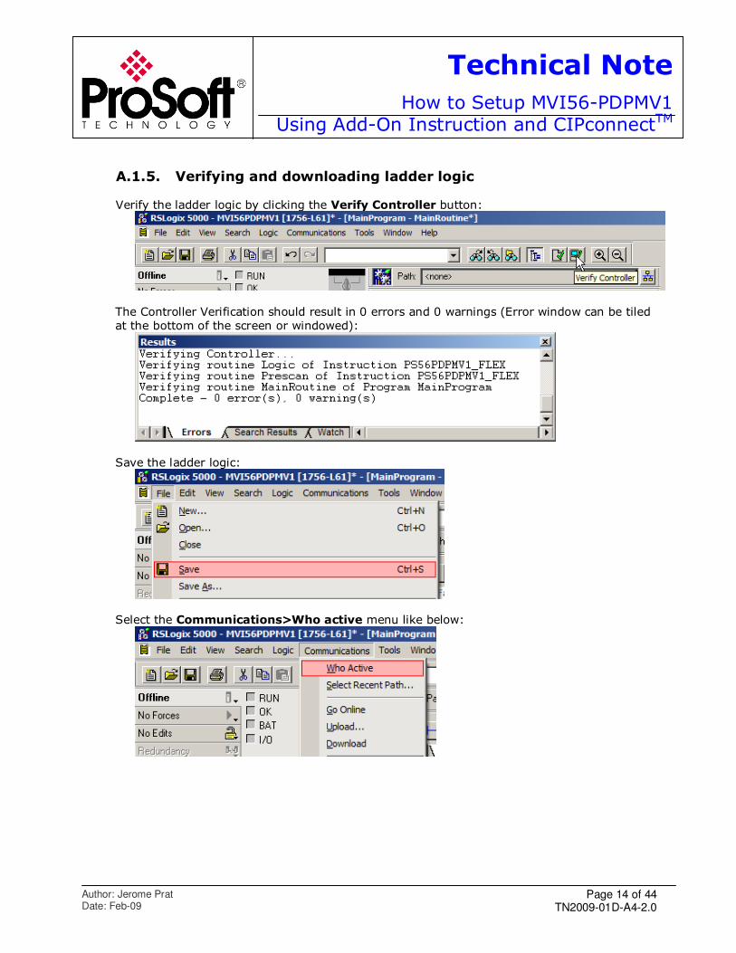
A.1.5. Verifying and downloading ladder logic
Verify the ladder logic by clicking the Verify Controller button:
The Controller Verification should result in 0 errors and 0 warnings (Error window can be tiled
at the bottom of the screen or windowed):
Save the ladder logic:
Select the Communications>Who active menu like below:
Page 15 of 44 TN2009-01D-A4-2.0
Technical Note
How to Setup MVI56-PDPMV1Using Add-On Instruction and CIPconnectTM
Author: Jerome Prat Date: Feb-09
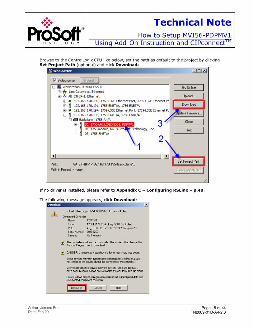
Browse to the ControlLogix CPU like below, set the path as default to the project by clicking Set Project Path (optional) and click Download:
If no driver is installed, please refer to Appendix C – Configuring RSLinx – p.40.
The following message appears, click Download:
Page 16 of 44 TN2009-01D-A4-2.0
Technical Note
How to Setup MVI56-PDPMV1Using Add-On Instruction and CIPconnectTM
Author: Jerome Prat Date: Feb-09
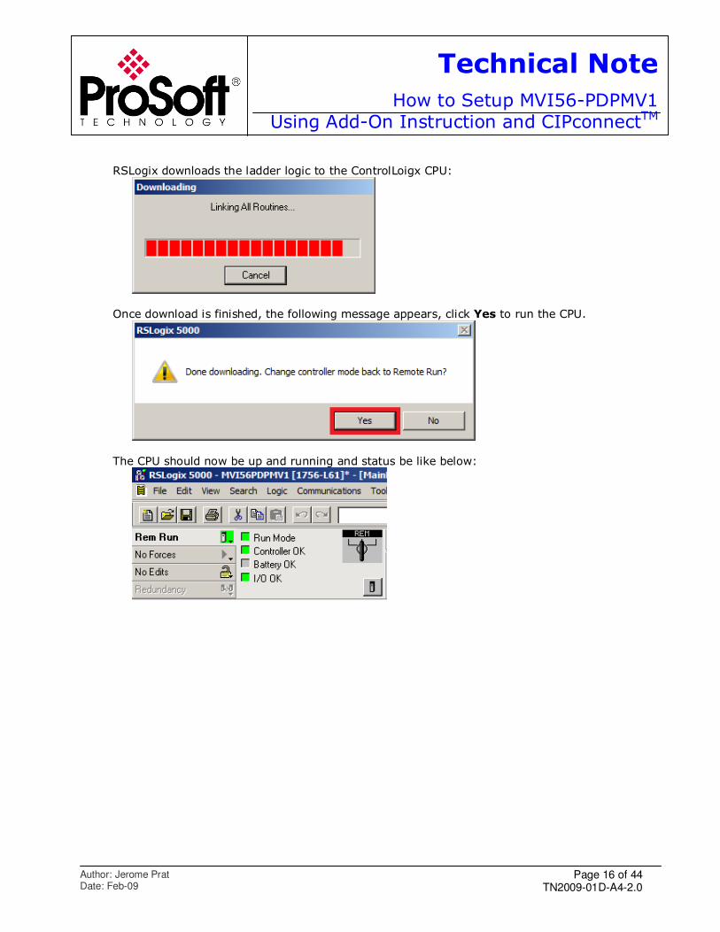
RSLogix downloads the ladder logic to the ControlLoigx CPU:
Once download is finished, the following message appears, click Yes to run the CPU.
The CPU should now be up and running and status be like below:
Page 17 of 44 TN2009-01D-A4-2.0
Technical Note
How to Setup MVI56-PDPMV1Using Add-On Instruction and CIPconnectTM
Author: Jerome Prat Date: Feb-09
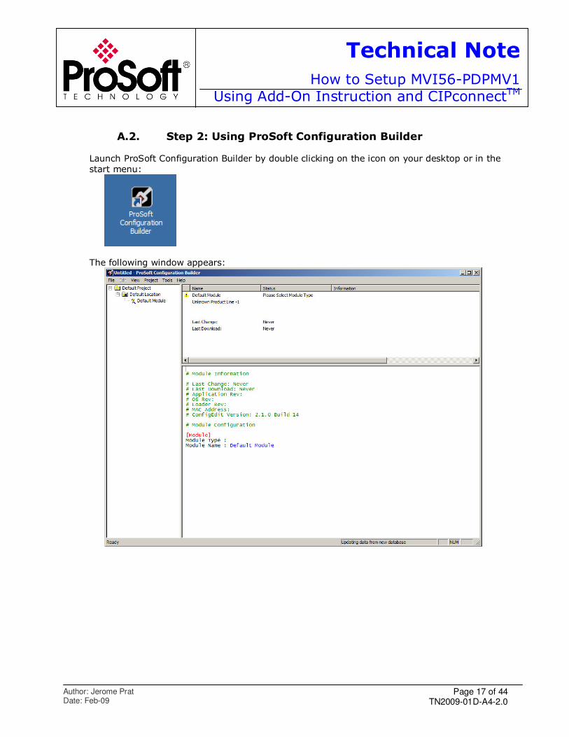
A.2. Step 2: Using ProSoft Configuration Builder
Launch ProSoft Configuration Builder by double clicking on the icon on your desktop or in the
start menu:
The following window appears:
Page 18 of 44 TN2009-01D-A4-2.0
Technical Note
How to Setup MVI56-PDPMV1Using Add-On Instruction and CIPconnectTM
Author: Jerome Prat Date: Feb-09
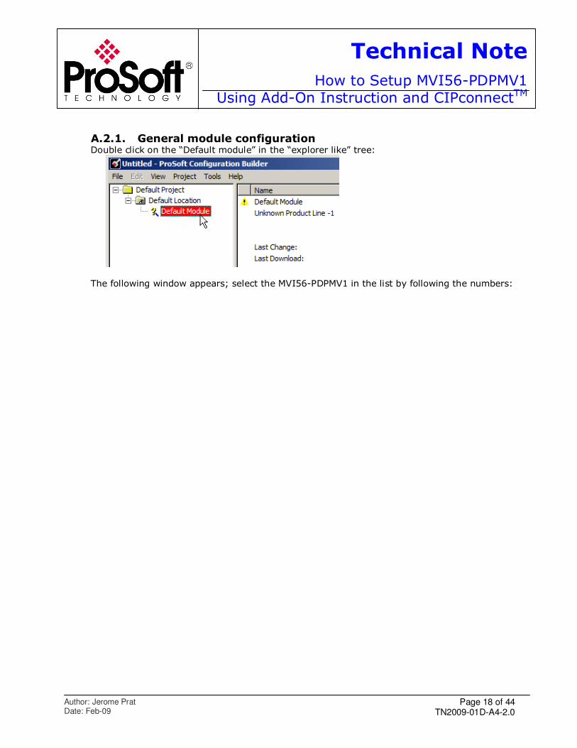
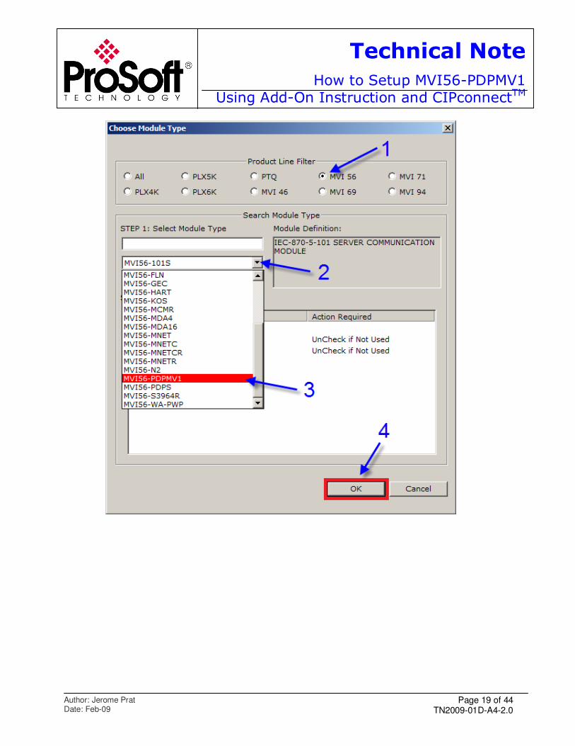
A.2.1. General module configuration Double click on the “Default module” in the “explorer like” tree:
The following window appears; select the MVI56-PDPMV1 in the list by following the numbers:
Page 19 of 44 TN2009-01D-A4-2.0
Technical Note
How to Setup MVI56-PDPMV1Using Add-On Instruction and CIPconnectTM
Author: Jerome Prat Date: Feb-09
Page 20 of 44 TN2009-01D-A4-2.0
Technical Note
How to Setup MVI56-PDPMV1Using Add-On Instruction and CIPconnectTM
Author: Jerome Prat Date: Feb-09
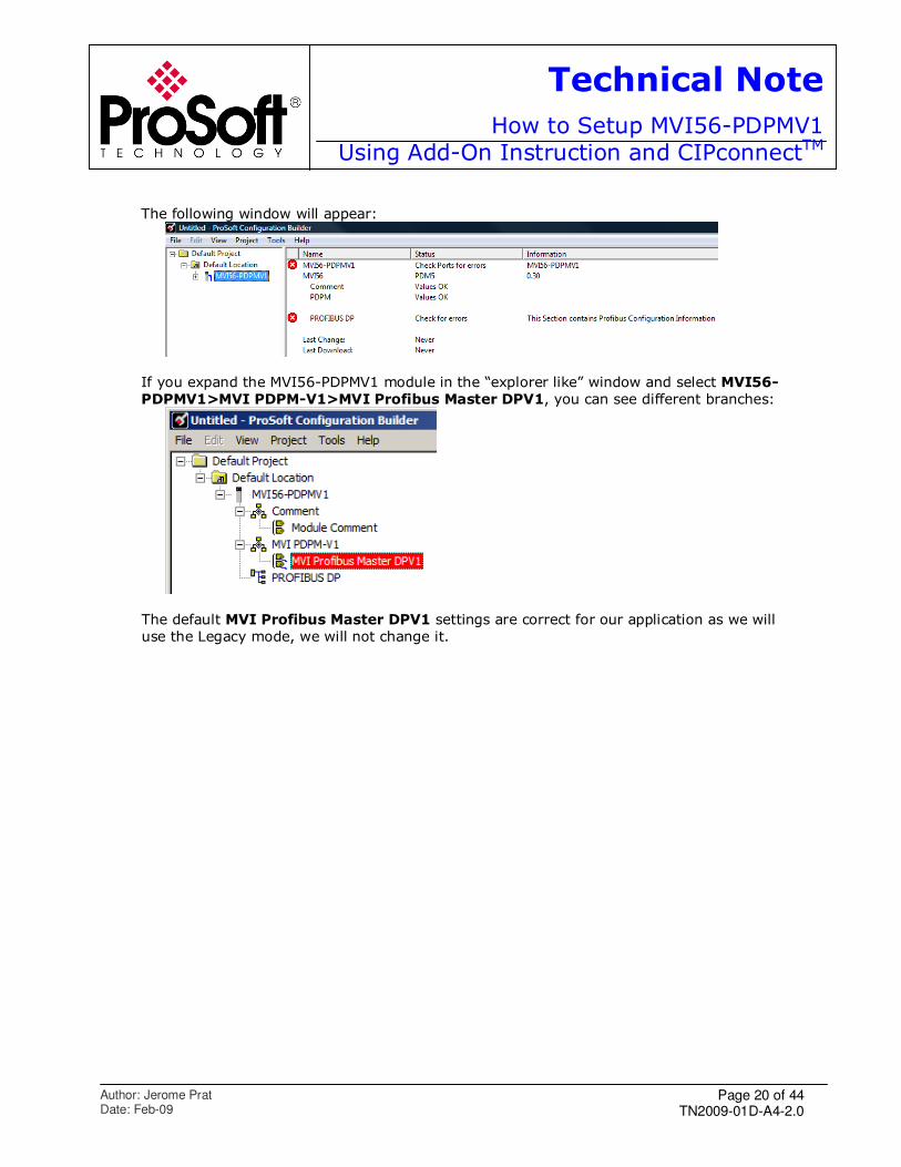
The following window will appear:
If you expand the MVI56-PDPMV1 module in the “explorer like” window and select MVI56-
PDPMV1>MVI PDPM-V1>MVI Profibus Master DPV1, you can see different branches:
The default MVI Profibus Master DPV1 settings are correct for our application as we will
use the Legacy mode, we will not change it.
Page 21 of 44 TN2009-01D-A4-2.0
Technical Note
How to Setup MVI56-PDPMV1Using Add-On Instruction and CIPconnectTM
Author: Jerome Prat Date: Feb-09
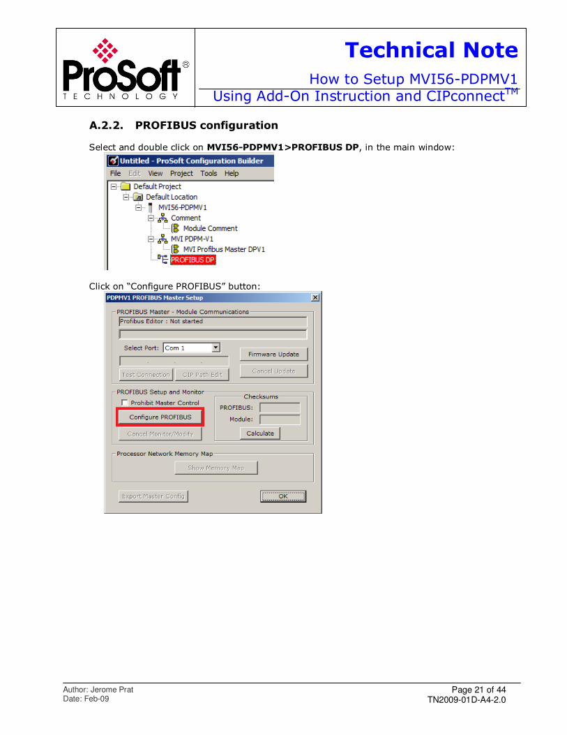
A.2.2. PROFIBUS configuration Select and double click on MVI56-PDPMV1>PROFIBUS DP, in the main window:
Click on “Configure PROFIBUS” button:
Page 22 of 44 TN2009-01D-A4-2.0
Technical Note
How to Setup MVI56-PDPMV1Using Add-On Instruction and CIPconnectTM
Author: Jerome Prat Date: Feb-09
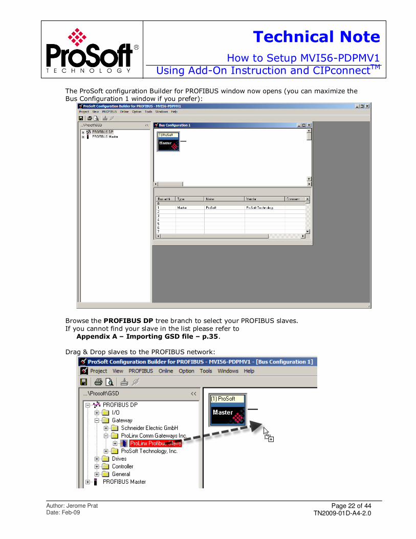
The ProSoft configuration Builder for PROFIBUS window now opens (you can maximize the Bus Configuration 1 window if you prefer):
Browse the PROFIBUS DP tree branch to select your PROFIBUS slaves.
If you cannot find your slave in the list please refer to
Appendix A – Importing GSD file – p.35.
Drag & Drop slaves to the PROFIBUS network:
Page 23 of 44 TN2009-01D-A4-2.0
Technical Note
How to Setup MVI56-PDPMV1Using Add-On Instruction and CIPconnectTM
Author: Jerome Prat Date: Feb-09
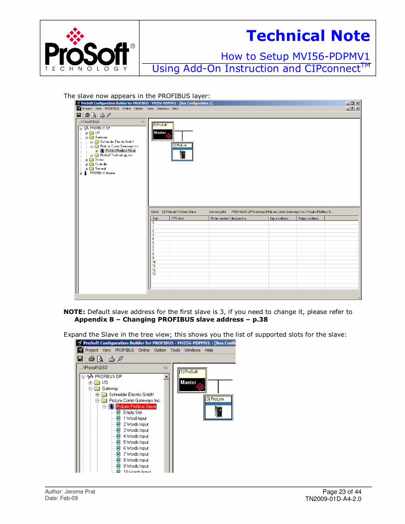
The slave now appears in the PROFIBUS layer:
NOTE: Default slave address for the first slave is 3, if you need to change it, please refer to
Appendix B – Changing PROFIBUS slave address – p.38
Expand the Slave in the tree view; this shows you the list of supported slots for the slave:
Page 24 of 44 TN2009-01D-A4-2.0
Technical Note
How to Setup MVI56-PDPMV1Using Add-On Instruction and CIPconnectTM
Author: Jerome Prat Date: Feb-09
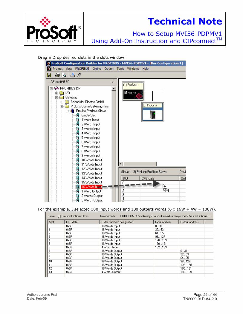
Drag & Drop desired slots in the slots window:
For the example, I selected 100 input words and 100 outputs words (6 x 16W + 4W = 100W).
Page 25 of 44 TN2009-01D-A4-2.0
Technical Note
How to Setup MVI56-PDPMV1Using Add-On Instruction and CIPconnectTM
Author: Jerome Prat Date: Feb-09
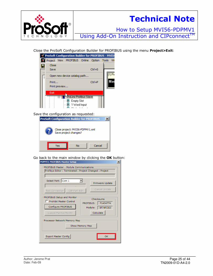
Close the ProSoft Configuration Builder for PROFIBUS using the menu Project>Exit:
Save the configuration as requested:
Go back to the main window by clicking the OK button:
Page 26 of 44 TN2009-01D-A4-2.0
Technical Note
How to Setup MVI56-PDPMV1Using Add-On Instruction and CIPconnectTM
Author: Jerome Prat Date: Feb-09
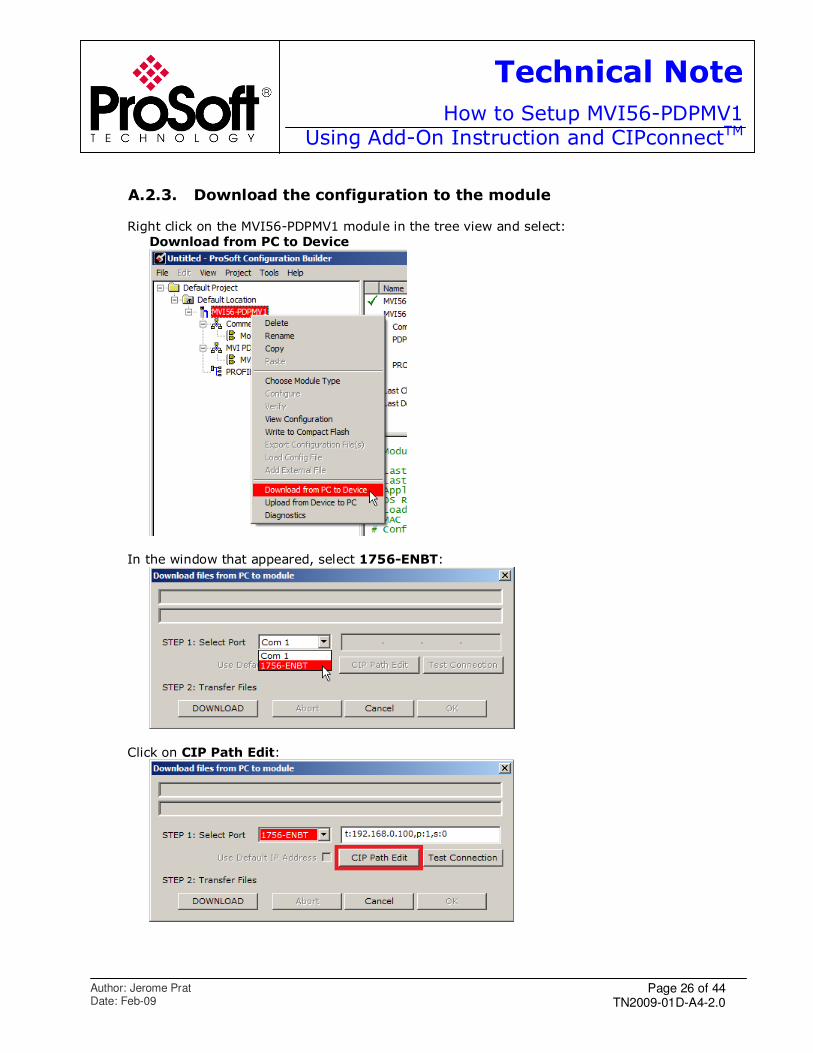
A.2.3. Download the configuration to the module
Right click on the MVI56-PDPMV1 module in the tree view and select:
Download from PC to Device
In the window that appeared, select 1756-ENBT:
Click on CIP Path Edit:
Page 27 of 44 TN2009-01D-A4-2.0
Technical Note
How to Setup MVI56-PDPMV1Using Add-On Instruction and CIPconnectTM
Author: Jerome Prat Date: Feb-09
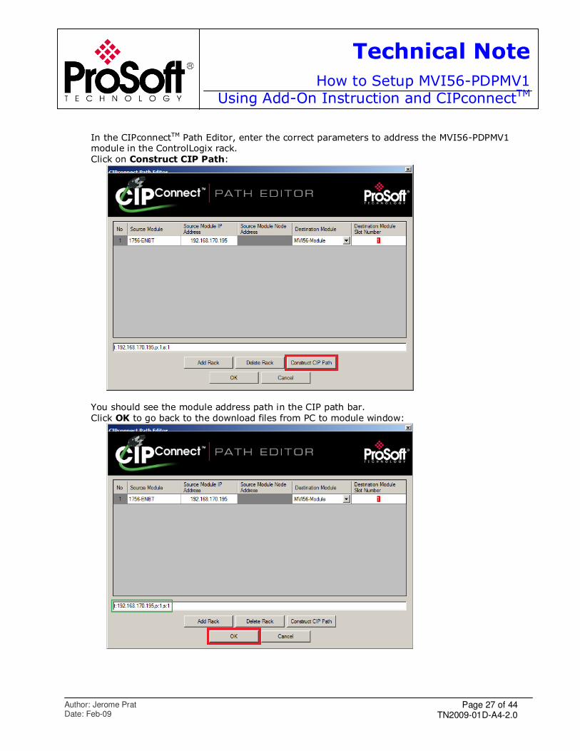
In the CIPconnectTM Path Editor, enter the correct parameters to address the MVI56-PDPMV1 module in the ControlLogix rack.
Click on Construct CIP Path:
You should see the module address path in the CIP path bar.
Click OK to go back to the download files from PC to module window:
Page 28 of 44 TN2009-01D-A4-2.0
Technical Note
How to Setup MVI56-PDPMV1Using Add-On Instruction and CIPconnectTM
Author: Jerome Prat Date: Feb-09
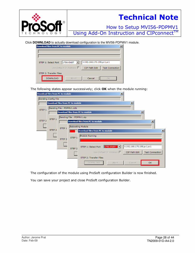
Click DOWNLOAD to actually download configuration to the MVI56-PDPMV1 module.
The following states appear successively; click OK when the module running:
The configuration of the module using ProSoft configuration Builder is now finished.
You can save your project and close ProSoft configuration Builder.
Page 29 of 44 TN2009-01D-A4-2.0
Technical Note
How to Setup MVI56-PDPMV1Using Add-On Instruction and CIPconnectTM
Author: Jerome Prat Date: Feb-09
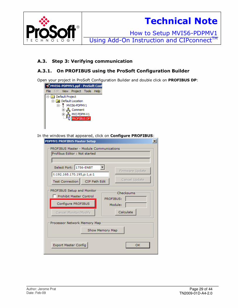
A.3. Step 3: Verifying communication
A.3.1. On PROFIBUS using the ProSoft Configuration Builder Open your project in ProSoft Configuration Builder and double click on PROFIBUS DP:
In the windows that appeared, click on Configure PROFIBUS:
Page 30 of 44 TN2009-01D-A4-2.0
Technical Note
How to Setup MVI56-PDPMV1Using Add-On Instruction and CIPconnectTM
Author: Jerome Prat Date: Feb-09
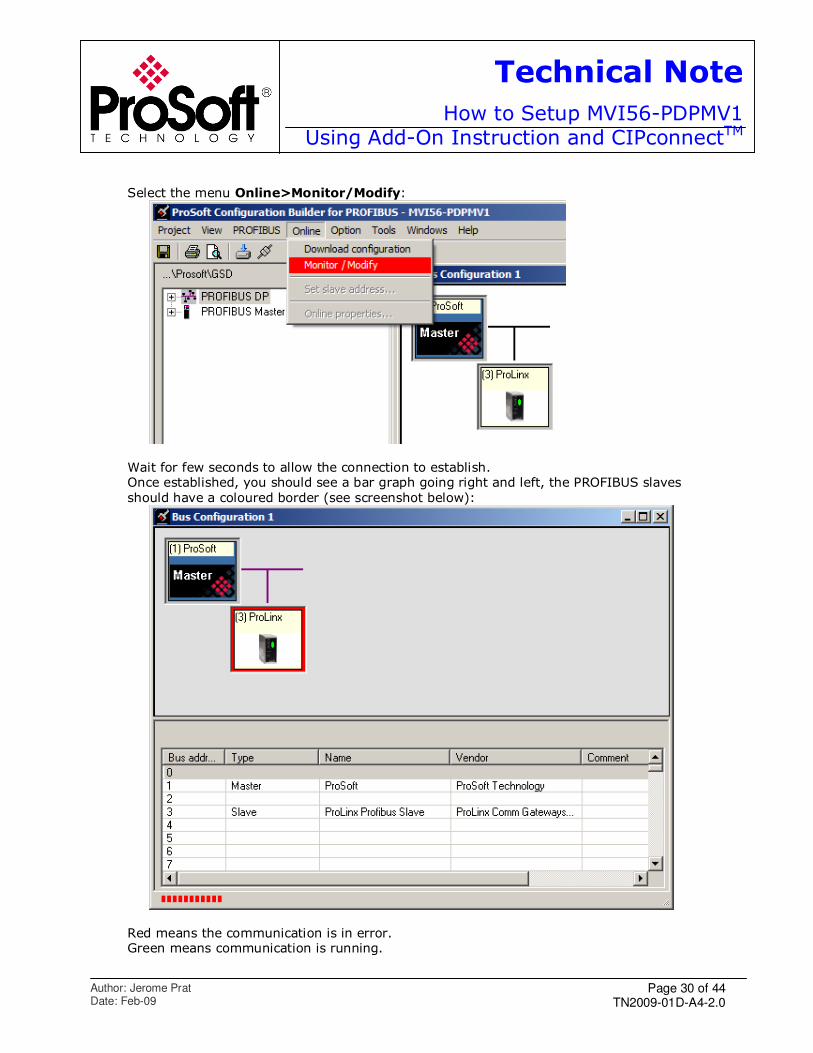
Select the menu Online>Monitor/Modify:
Wait for few seconds to allow the connection to establish. Once established, you should see a bar graph going right and left, the PROFIBUS slaves
should have a coloured border (see screenshot below):
Red means the communication is in error. Green means communication is running.
Page 31 of 44 TN2009-01D-A4-2.0
Technical Note
How to Setup MVI56-PDPMV1Using Add-On Instruction and CIPconnectTM
Author: Jerome Prat Date: Feb-09
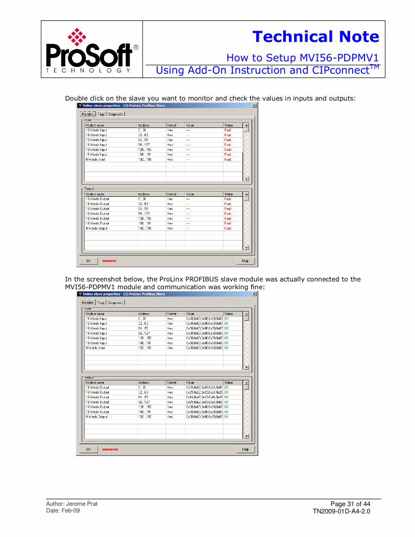
Double click on the slave you want to monitor and check the values in inputs and outputs:
In the screenshot below, the ProLinx PROFIBUS slave module was actually connected to the
MVI56-PDPMV1 module and communication was working fine:
Page 32 of 44 TN2009-01D-A4-2.0
Technical Note
How to Setup MVI56-PDPMV1Using Add-On Instruction and CIPconnectTM
Author: Jerome Prat Date: Feb-09
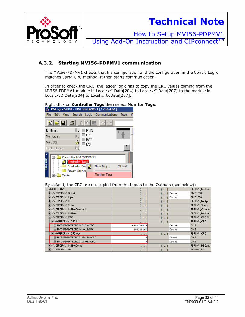
A.3.2. Starting MVI56-PDPMV1 communication
The MVI56-PDPMV1 checks that his configuration and the configuration in the ControlLogix
matches using CRC method, it then starts communication.
In order to check the CRC, the ladder logic has to copy the CRC values coming from the
MVI56-PDPMV1 module in Local:x:I.Data[204] to Local:x:I.Data[207] to the module in Local:x:O.Data[204] to Local:x:O.Data[207].
Right click on Controller Tags then select Monitor Tags:
By default, the CRC are not copied from the Inputs to the Outputs (see below):
Page 33 of 44 TN2009-01D-A4-2.0
Technical Note
How to Setup MVI56-PDPMV1Using Add-On Instruction and CIPconnectTM
Author: Jerome Prat Date: Feb-09
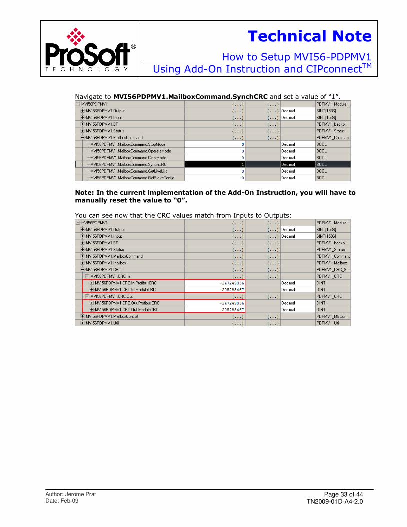
Navigate to MVI56PDPMV1.MailboxCommand.SynchCRC and set a value of “1”.
Note: In the current implementation of the Add-On Instruction, you will have to
manually reset the value to “0”.
You can see now that the CRC values match from Inputs to Outputs:

Page 34 of 44 TN2009-01D-A4-2.0
Technical Note
How to Setup MVI56-PDPMV1Using Add-On Instruction and CIPconnectTM
Author: Jerome Prat Date: Feb-09
Page 35 of 44 TN2009-01D-A4-2.0
Technical Note
How to Setup MVI56-PDPMV1Using Add-On Instruction and CIPconnectTM
Author: Jerome Prat Date: Feb-09
B. APPENDIX
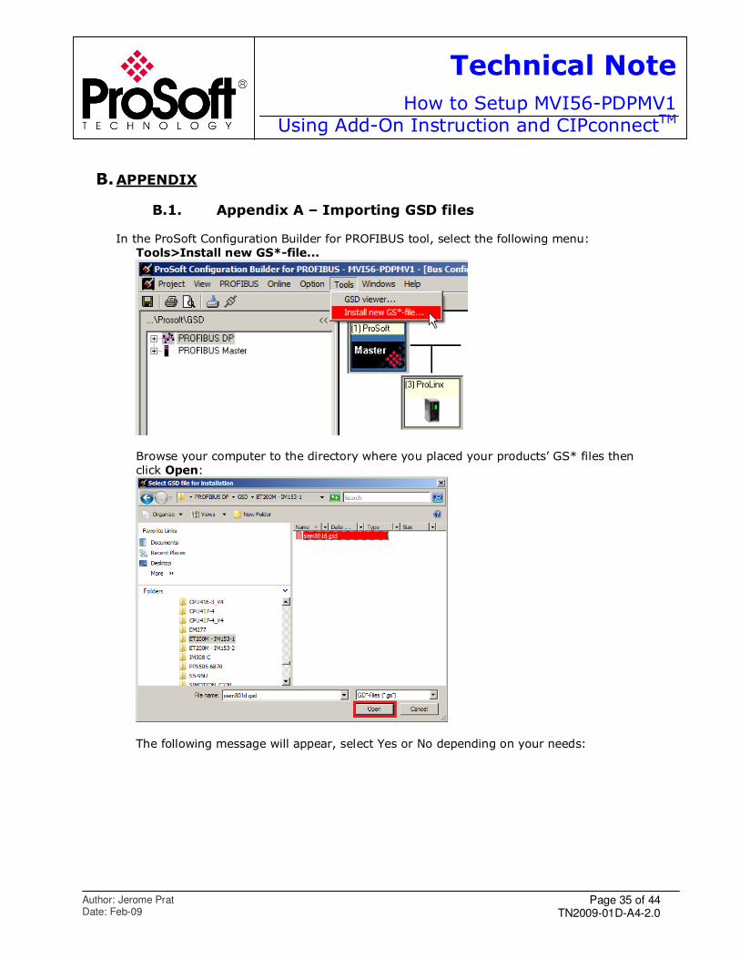
B.1. Appendix A – Importing GSD files In the ProSoft Configuration Builder for PROFIBUS tool, select the following menu:
Tools>Install new GS*-file...
Browse your computer to the directory where you placed your products’ GS* files then
click Open:
The following message will appear, select Yes or No depending on your needs:

Page 36 of 44 TN2009-01D-A4-2.0
Technical Note
How to Setup MVI56-PDPMV1Using Add-On Instruction and CIPconnectTM
Author: Jerome Prat Date: Feb-09
Page 37 of 44 TN2009-01D-A4-2.0
Technical Note
How to Setup MVI56-PDPMV1Using Add-On Instruction and CIPconnectTM
Author: Jerome Prat Date: Feb-09
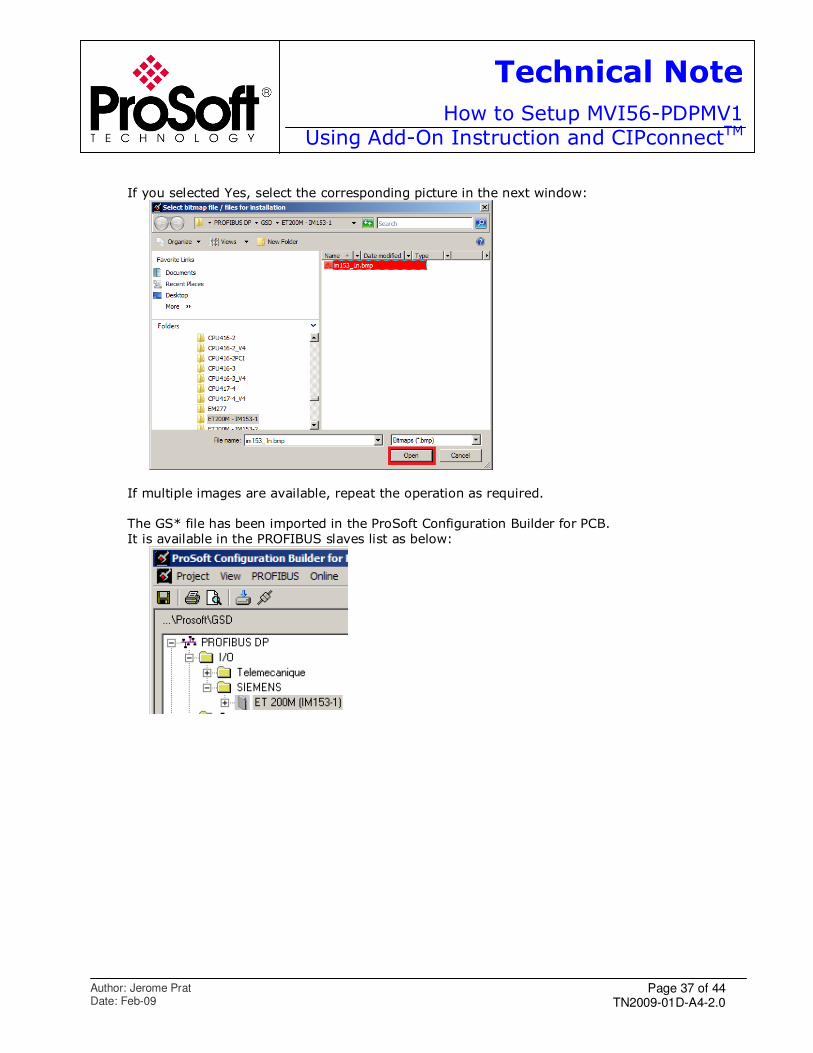
If you selected Yes, select the corresponding picture in the next window:
If multiple images are available, repeat the operation as required.
The GS* file has been imported in the ProSoft Configuration Builder for PCB.
It is available in the PROFIBUS slaves list as below:
Page 38 of 44 TN2009-01D-A4-2.0
Technical Note
How to Setup MVI56-PDPMV1Using Add-On Instruction and CIPconnectTM
Author: Jerome Prat Date: Feb-09
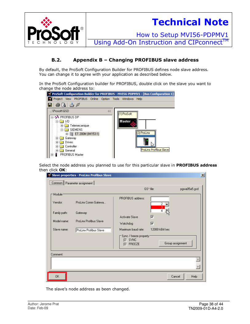
B.2. Appendix B – Changing PROFIBUS slave address
By default, the ProSoft Configuration Builder for PROFIBUS defines node slave address.
You can change it to agree with your application as described below.
In the ProSoft Configuration builder for PROFIBUS, double click on the slave you want to
change the node address to:
Select the node address you planned to use for this particular slave in PROFIBUS address
then click OK:
The slave’s node address as been changed.

Page 39 of 44 TN2009-01D-A4-2.0
Technical Note
How to Setup MVI56-PDPMV1Using Add-On Instruction and CIPconnectTM
Author: Jerome Prat Date: Feb-09
You have to download the configuration to the module.
Page 40 of 44 TN2009-01D-A4-2.0
Technical Note
How to Setup MVI56-PDPMV1Using Add-On Instruction and CIPconnectTM
Author: Jerome Prat Date: Feb-09
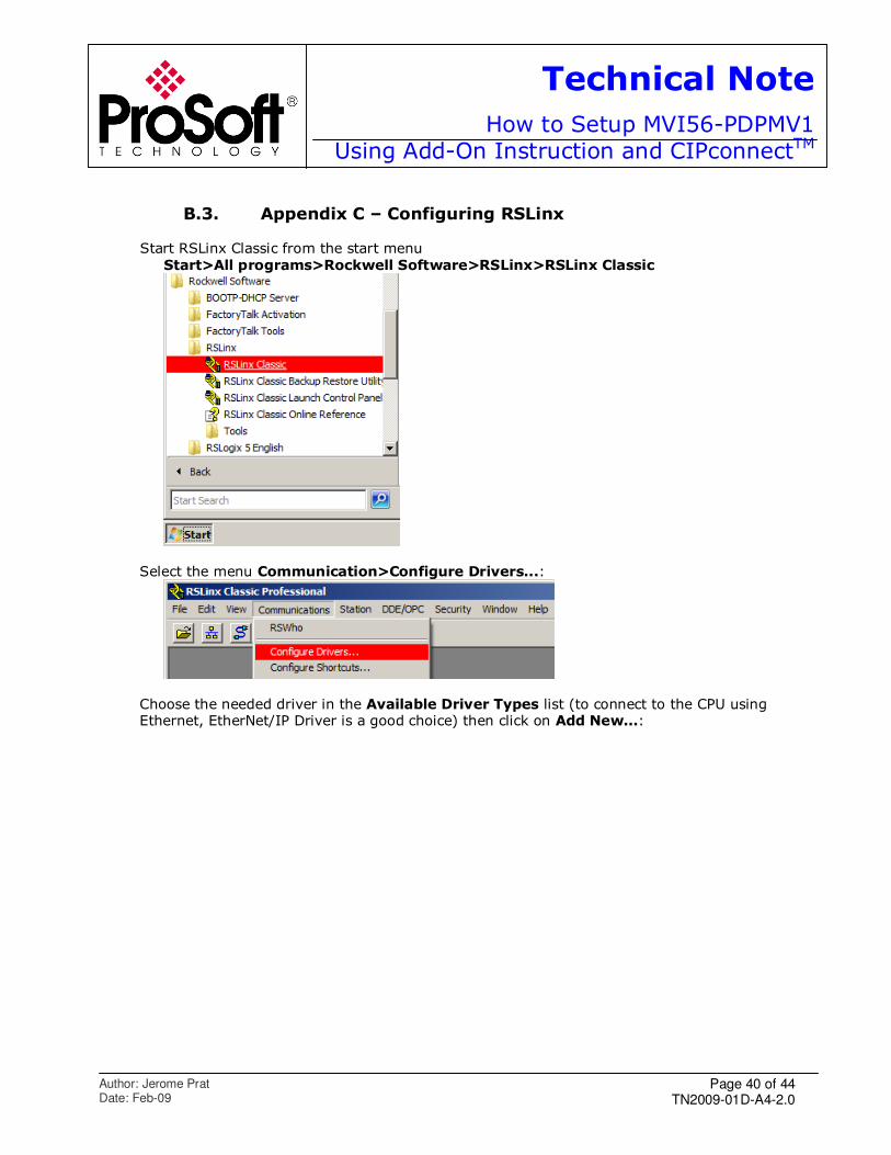
B.3. Appendix C – Configuring RSLinx
Start RSLinx Classic from the start menu
Start>All programs>Rockwell Software>RSLinx>RSLinx Classic
Select the menu Communication>Configure Drivers...:
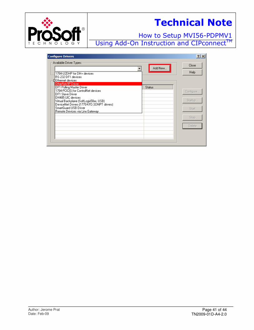
Choose the needed driver in the Available Driver Types list (to connect to the CPU using Ethernet, EtherNet/IP Driver is a good choice) then click on Add New...:
Page 41 of 44 TN2009-01D-A4-2.0
Technical Note
How to Setup MVI56-PDPMV1Using Add-On Instruction and CIPconnectTM
Author: Jerome Prat Date: Feb-09
Page 42 of 44 TN2009-01D-A4-2.0
Technical Note
How to Setup MVI56-PDPMV1Using Add-On Instruction and CIPconnectTM
Author: Jerome Prat Date: Feb-09
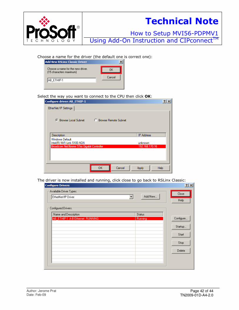
Choose a name for the driver (the default one is correct one):
Select the way you want to connect to the CPU then click OK:
The driver is now installed and running, click close to go back to RSLinx Classic:

Page 43 of 44 TN2009-01D-A4-2.0
Technical Note
How to Setup MVI56-PDPMV1Using Add-On Instruction and CIPconnectTM
Author: Jerome Prat Date: Feb-09
Exit RSLinx and go back to RSLogix, your driver would be available and you should be able to connect to the CPU.

TN2009-01D-A4-2.0 Feb-09
www.prosoft-technology.com
Technical Note
For further information feel free to contact ProSoft Technology Technical Support at
one of the following addresses:
Europe & Africa: ProSoft Technology Blagnac (Toulouse), France
+33 (0)5.3436.8720 Phone +33 (0)5.6178.4052 Fax [email protected]
Middle East: ProSoft Technology Dubai, United Arab Emirates +971 (0)4.214.6911 Phone
+971 (0)4.214.6912 Fax
North America: ProSoft Technology
Bakersfield, California USA
+1 (661) 716.5100 Phone +1 (661) 716.5110 Fax
Latin America: ProSoft Technology The Woodlands (Houston), Texas USA
+1 (281) 298.9109 Phone
+1 (281) 298.9336 Fax [email protected]
Asia & Pacific: ProSoft Technology
Salangor (Kuala Lumpur), Malaysia +603 7724.2080 Phone +603 7724.2090 Fax