technical manual - hennypenny.com · safety alert symbol is used with danger, warning, or caution...
TRANSCRIPT
TECHNICAL MANUAL
Henny PennyEvolution Elite®
Reduced Oil Capacity Open Fryers (Split Vat & Full Vat– Electric)
Wendy’sModel EEE-153Model EEE-154


Model EEE-153, 154
i
TABLE OF CONTENTS
Section Page
Section 1. TROUBLESHOOTING ................................................................................... 1-1 1-1 Introduction .......................................................................................... 1-1 1-2 Safety .................................................................................................... 1-1 1-3 Troubleshooting .................................................................................... 1-2 1-4 Error Code Table .................................................................................. 1-7
Section 2. INFO & FILTER BUTTON STATS ................................................................. 2-1 2-1 INFO Button Stats ................................................................................ 2-1 2-2 FILTER Button Stats ............................................................................ 2-1
Section 3. INFORMATION MODE .................................................................................. 3-1 3-1 Information Mode Details .................................................................... 3-1 Section 4. Product Program Mode .................................................................................... 4-1 4-1 Modifying Product Settings .................................................................. 4-1 Section 5. LEVEL 2 PROGRAMMING ........................................................................... 5-1 5-1 Special Program Mode ......................................................................... 5-1 5-2 Do Not Disburb .................................................................................... 5-10 5-3 Clock Set .............................................................................................. 5-11 5-4 Data Logging, Heat Control, Tech, Stat & Filter Control Modes ........ 5-11 5-5 Tech Mode ............................................................................................ 5-12 5-6 Stats Mode ............................................................................................ 5-18
Section 6. MAINTENANCE SECTION ........................................................................... 6-1 6-1 Intoduction ............................................................................................ 6-1 6-2 Maintenance Hints ................................................................................ 6-1 6-3 Preventive Maintenance ...................................................................... 6-1 6-4 Control Panel and Menu Card Replacement ........................................ 6-2 6-5 High Temperature Limit Control .......................................................... 6-3 6-6 Breakers ................................................................................................ 6-7 6-7 Main Power switch ............................................................................... 6-8
FM06-046 Revised 1-22-16
Sept. 2011
Model EEE-153, 154
ii
Section 6. MAINTENANCE SECTION (Continued) 6-8 Temperature Probe Replacement .......................................................... 6-8 6-9 Oil Channel Clean-Out ......................................................................... 6-10 6-10 Element Safety Switch ......................................................................... 6-11 6-11 Contactors ............................................................................................. 6-12 6-12 Solenoid Valves .................................................................................... 6-14 6-13 Filter Pump & Motor ............................................................................ 6-16 6-14 JIB Pump .............................................................................................. 6-19 6-15 Express Filter PC Board ....................................................................... 6-19 6-16 Transformers ......................................................................................... 6-20 6-17 Filter Motor Relay ................................................................................ 6-21 6-18 Drain Pan Switch .................................................................................. 6-22 6-19 Filter Beacon® ....................................................................................... 6-23 6-20 Oil Level Probes ................................................................................... 6-24 6-21 Drain Rod Switch ................................................................................. 6-26 6-22 Time-Delay-Relays ............................................................................... 6-27 Wiring Diagrams - 208/240V .................................................................................. 6-29
Section 7. PARTS SECTION 7-1 Introduction .......................................................................................... 7-1 7-2 Genuine Parts ....................................................................................... 7-1 7-3 How To Order ....................................................................................... 7-1 7-4 Prices .................................................................................................... 7-1 7-5 Delivery ................................................................................................ 7-1 7-6 Warranty ............................................................................................... 7-1 Spare Parts Lists
TABLE OF CONTENTS
Section Page
Sept. 2011
Model EEE-153, 154
1-1
1-1. INTRODUCTION This section provides troubleshooting information in the form of an easy to read table.
Ifaproblemoccursduringthefirstoperationofanewfryer, recheck the installation per the Installation Section of this manual. Before troubleshooting, always recheck the operation pro- cedures per Section 3 of this manual.
SECTION 1. TROUBLESHOOTING
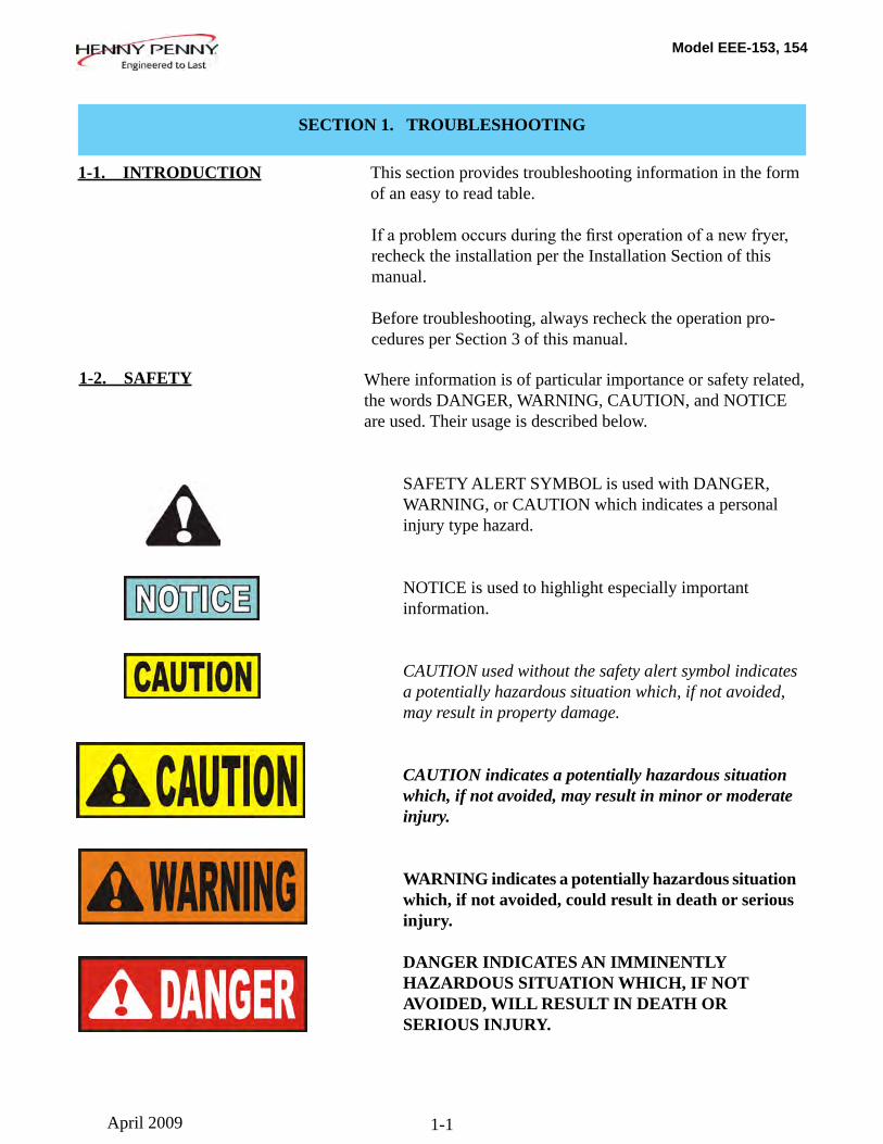
Where information is of particular importance or safety related, the words DANGER, WARNING, CAUTION, and NOTICE are used. Their usage is described below.
SAFETY ALERT SYMBOL is used with DANGER, WARNING, or CAUTION which indicates a personal injury type hazard.
NOTICE is used to highlight especially important information.
CAUTION used without the safety alert symbol indicates a potentially hazardous situation which, if not avoided, may result in property damage.
CAUTION indicates a potentially hazardous situation which, if not avoided, may result in minor or moderate injury.
WARNING indicates a potentially hazardous situation which, if not avoided, could result in death or serious injury.
DANGER INDICATES AN IMMINENTLY HAZARDOUS SITUATION WHICH, IF NOT AVOIDED, WILL RESULT IN DEATH OR SERIOUS INJURY.
1-2. SAFETY
April 2009
Model EEE-153, 154
1-2
1-3. TROUBLESHOOTING To isolate a malfunction, proceed as follows:
1. Clearlydefinetheproblem(orsymptom)andwhenit occurs.
2. Locate the problem in the Troubleshooting table.
3. Review all possible causes. Then, one-at-a-time work through the list of corrections until the problem is solved.
4. Refer to the maintenance procedures in the Maintenance Section to safely and properly make the checkout and repair needed.
If maintenance procedures are not followed correctly, injuries and/or property damage could result.
April 2009
Model EEE-153, 154
1-3
Problem Cause Correction POWER SECTION
With power switch in • Open circuit • Check to see that unit is plugged in ON position, the fryer is completely inoperative • Check the breaker or fuse at supply box (NO POWER) • Check voltage at wall receptacle • Check MAIN POWER switch; replace if defective • Check cord and plug
• Check circuit breakers in fryer
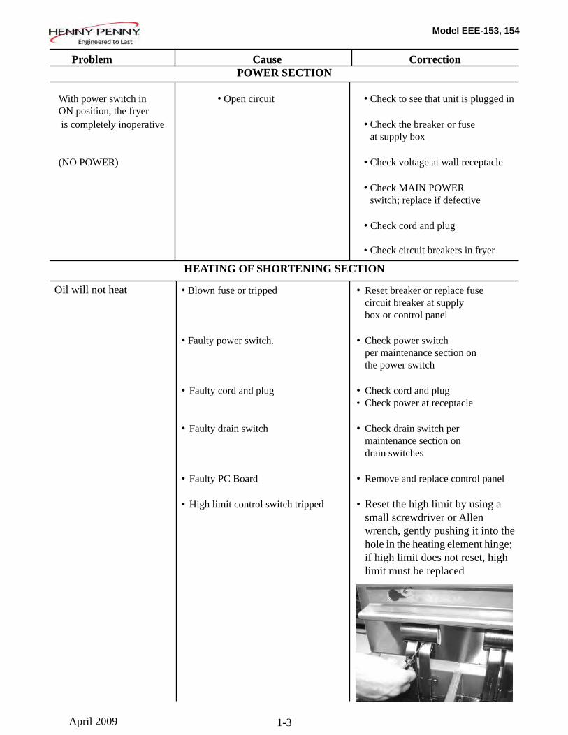
• Blown fuse or tripped • Reset breaker or replace fuse circuit breaker at supply box or control panel • Faulty power switch. • Check power switch per maintenance section on the power switch • Faulty cord and plug • Check cord and plug • Check power at receptacle • Faulty drain switch • Check drain switch per maintenance section on drain switches • Faulty PC Board • Remove and replace control panel • High limit control switch tripped • Reset the high limit by using a small screwdriver or Allen wrench, gently pushing it into the hole in the heating element hinge; if high limit does not reset, high limit must be replaced
HEATING OF SHORTENING SECTION
Oil will not heat
April 2009
Model EEE-153, 154
1-4
Problem Cause Correction
HEATING OF SHORTENING SECTION (Continued)
• Drain valve open • Close drain valve (Continued) • Possible faulty temperature probe • Replace temperature probe
• Faulty contactor • Check contactor per maintenance section on contactors
• Breaker on fryer tripped • Check breakers on fryer per maintenance section on breakers
Oil heating too slow • Low or improper voltage • Use a meter and check the receptacle against data plate
• Weak or burnt out element(s) • Check heating element(s) per Element Replacement Section
• Points in contactor bad • Check contactor per Contactor Replacement Section
• Wire(s) loose • Tighten
• Burnt or charred wire • Replace wire and clean connection connectors
Oil • Programming wrong • Check temperature setting overheating in the program mode • Faulty PC board • Replace control board if heat indicator stays on past ready temperature • Faulty temperature probe • Check probe calibration and replace if temperature is off + 5 degress
• Check contactor for not • Check faulty contactor per opening Contactor Replacement Section
Oil will not heat
April 2009
Model EEE-153, 154
1-5
Problem Cause Correction
OIL LEVEL SECTION
Oil foaming or boiling over vat • Water in oil • At end of a Cook Cycle,drain vat and clean vat; add fresh oil • Improper or bad oil • Use recommended oil •Improperfiltering •Refertotheprocedure coveringfilteringtheoil • Bottom of vat full of crumbs • Filter oil • Improper rinsing after • Rinse the vat thoroughly to remove cleaning the fryer any cleaning agent in the vat Oil will not drain from vat • Drain valve clogged with • Open valve, force cleaning brush crumbs through drain
• Oil channel clogged • Access the clean-out plug on the sides of the unit (see Oil Channel Clean-out Section)
Oil leaking • Obstruction in drain • Remove obstruction through drain valve • Faulty drain valve • Replace drain valve
Vatisunder-filled • JIBisloworempty •FilltheJIB • JIB oil line is clogged or • Check JIB line collapsed
•Filterpanneedscleaned •Cleanfilterpanandchangepad
Bubblesinoilduring •Filterpannotcompletely •Makesurefilterpanreturnlineisentirefilteringprocess engaged pushedcompletelyintothereceiver on the fryer • Filter pan clogged • Clean pan and change pad
•Damagedo-ringonfilter •ChangeO-ring line tube on fryer
April 2009
Model EEE-153, 154
1-6
Problem Cause Correction
FILTER MOTOR SECTION Filter motor runs but pumps oil slowly
Filter motor will not run
“ISPOTFILLED”filtererror prompt
“CHECK PAN” prompt
“FILTER PAN MISSING” prompt appears
“CHANGE FILTER PAD” prompt appears
• Filter line connections loose
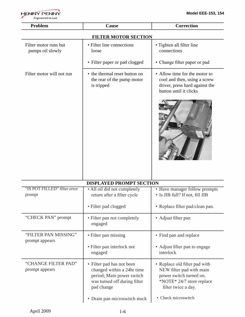
• Filter paper or pad clogged • the thermal reset button on the rear of the pump motor is tripped
• All oil did not completely returnafterafiltercycle
• Filter pad clogged
• Filter pan not completely engaged
• Filter pan missing
• Filter pan interlock not engaged
• Filter pad has not been changed within a 24hr time period; Main power switch wasturnedoffduringfilter pad change
• Drain pan microswitch stuck
•Tightenallfilterline connections
• Changefilterpaperorpad
• Allow time for the motor to cool and then, using a screw driver, press hard against the button until it clicks
• Have manager follow prompts• IsJIBfull?Ifnot,fillJIB
•Replacefilterpad/cleanpan.
•Adjustfilterpan
• Find pan and replace
•Adjustfilterpantoengage interlock
•Replaceoldfilterpadwith NEWfilterpadwithmain power switch turned on. *NOTE* 24/7 store replace filtertwiceaday.
• Check microswitch
DISPLAYED PROMPT SECTION
April 2009
Model EEE-153, 154
1-7
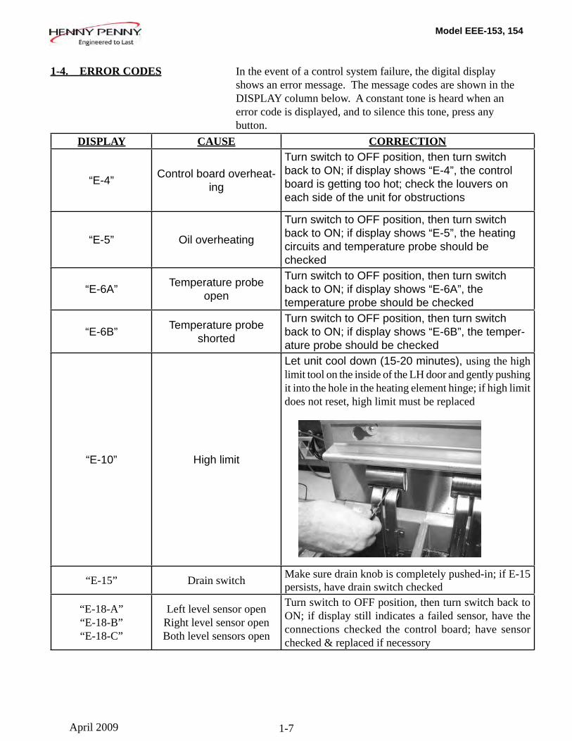
1-4. ERROR CODES In the event of a control system failure, the digital display shows an error message. The message codes are shown in the DISPLAY column below. A constant tone is heard when an error code is displayed, and to silence this tone, press any button.
April 2009
DISPLAY CAUSE CORRECTION
“E-4” Control board overheat-ing
Turn switch to OFF position, then turn switch back to ON; if display shows “E-4”, the control board is getting too hot; check the louvers on each side of the unit for obstructions
“E-5” Oil overheating
Turn switch to OFF position, then turn switch back to ON; if display shows “E-5”, the heating circuits and temperature probe should be checked
“E-6A” Temperature probe open
Turn switch to OFF position, then turn switch back to ON; if display shows “E-6A”, the temperature probe should be checked
“E-6B” Temperature probe shorted
Turn switch to OFF position, then turn switch back to ON; if display shows “E-6B”, the temper-ature probe should be checked
“E-10” High limit
Let unit cool down (15-20 minutes), using the high limit tool on the inside of the LH door and gently pushing it into the hole in the heating element hinge; if high limit does not reset, high limit must be replaced
“E-15” Drain switch Make sure drain knob is completely pushed-in; if E-15 persists, have drain switch checked
“E-18-A”“E-18-B”“E-18-C”
Left level sensor openRight level sensor openBoth level sensors open
Turn switch to OFF position, then turn switch back to ON; if display still indicates a failed sensor, have the connections checked the control board; have sensor checked & replaced if necessory
Model EEE-153, 154
1-8
1-4. ERROR CODES (Continued)
July 2014
“E-21” Slow heat recovery
Haveacertifiedservicetechniciancheckthefryerforcorrect voltage to the unit; have heat circuit checked; have unit checked for loose or burnt wire
“E-22” “NO HEAT”
“CHECKPWR CORD AND
BREAKER”
Elements not
Have power cord and heat circuit checked heating
“E-31” Elements are up Lower elements completely back into the vat
“E-41”, “E-46” Programming
Press power button to vat off and back on again, if anyfailure of the error codes, have the controls reinitialized; if error code persists, have the control board replaced
“E-47” Analog converter chip or 12 volt supply failure
Press power button to vat off and back on again, if “E-47” persists, have the I/O board, or the PC board replaced; if speaker tones are quiet, probably I/O board failure; have the I/O board replaced
“E-48” Input system error Have PC board replaced
“E-54C” Temperature inputTurn switch to OFF, then back to ON; have con-trol PC error board replaced if “E-54C” persists
“E-60”AIF PC board not
communicating with control PC board
Press power button to turn vat off, wait 15 seconds, and turn back on again. If “E-60” persists, have connector between the PC boards checked; replace AIF PC board or control PC board, if necessary
“E-93-A” “24 VDC SUPPLY
TRIPPED”
Autolift motor malfunction or failure
• If AutoLift feature is not operating, have each of the Autolift motors checked
• Check the 24V Circuts
DISPLAY CAUSE CORRECTION
Model EEE-153, 154
2-1
SECTION 2. INFO & FILTER BUTTON STATS
2-1. INFO BUTTON STATS
Actual Oil Temperature1. Press and the actual oil temperature shows in the display, for each vat.
Set-point Temperature2. Press twice and SP shows in the display, along with the set-point (preset) temperature of each vat.
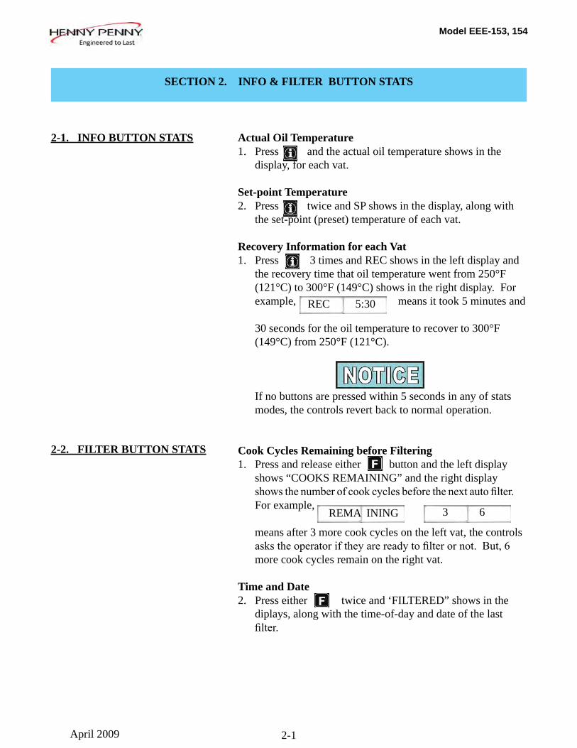
Recovery Information for each Vat1. Press 3 times and REC shows in the left display and the recovery time that oil temperature went from 250°F (121°C) to 300°F (149°C) shows in the right display. For example, means it took 5 minutes and
30 seconds for the oil temperature to recover to 300°F (149°C) from 250°F (121°C).
If no buttons are pressed within 5 seconds in any of stats modes, the controls revert back to normal operation.
Cook Cycles Remaining before Filtering1. Press and release either button and the left display shows “COOKS REMAINING” and the right display showsthenumberofcookcyclesbeforethenextautofilter. For example,
means after 3 more cook cycles on the left vat, the controls askstheoperatoriftheyarereadytofilterornot.But,6 more cook cycles remain on the right vat.
Time and Date2. Press either twice and ‘FILTERED” shows in the diplays, along with the time-of-day and date of the last filter.
REC 5:30
2-2. FILTER BUTTON STATS
REMA INING 3 6
April 2009
Model EEE-153, 154
3-1
SECTION 3. INFORMATION MODE
This historic information can be recorded and used for opera-tional and technical help and allows you to view the following:
• 1. E-LOG• 2. LAST LOAD• 3. DAILY STATS• 4. OIL STATS• 5. REVIEW USAGE• 6. INPUTS• 7. OUTPUTS• 8. OIL TEMP
Not all Information Mode functions are discussed in this section. To ensure proper operation of fryer, please consult Henny Penny Corp. before changing any of these settings. For more information on these functions, contact Technical Support at 1-800-417- 8405, or 1-937-456-8405.
1. E-LOG (error code log)Press and buttons at the same time and “*INFO
MODE*” shows in the display, followed by “1. E-LOG”.
Press and to exit Information Mode at any time.
Press and “A. (date & time) *NOW* show in displays. This is the present date and time.
Press and if a error was recorded, “B. (date, time, and error code information)” shows in display. This is the latest error code that the controls recorded.
Press and the next latest error code information can be seen.
Up to 10 error codes (B to K) can be stored in the E-LOG section.
• 9. CPU TEMP• 10. COMMUNICATION INFO• 11. ANALOG INFO• 12. ACTIVITY LOG• 13. OIL LEVELS• 14. PUMP VALVE INFO• 15. AIF INFO
3-1. INFORMATION MODE DETAILS
April 2009
Model EEE-153, 154
3-2
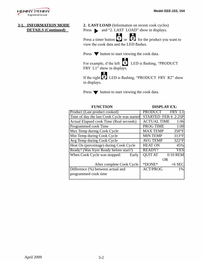
2. LAST LOAD (Information on recent cook cycles)Press and “2. LAST LOAD” show in displays.
Press a timer button or for the product you want to viewthecookdataandtheLEDflashes.
Press button to start viewing the cook data.
Forexample,iftheleft LEDisflashing,“PRODUCTFRY L1” show in displays.
Iftheright LEDisflashing,“PRODUCTFRYR2”showin displays.
Press button to start viewing the cook data.
3-1. INFORMATION MODE DETAILS (Continued)
FUNCTION DISPLAY EX:Product (Last product cooked) PRODUCT FRY L1Time of day the last Cook Cycle was started STARTED FEB 4 2:25PActual Elapsed cook Time (Real seconds) ACTUAL TIME 1:06Programmed cook Time PROG TIME 1:00Max Temp during Cook Cycle MAX TEMP 350°FMin Temp during Cook Cycle MIN TEMP 313°FAvg Temp during Cook Cycle AVG TEMP 322°FHeat On (percentage) during Cook Cycle HEAT ON 45%Ready? (Was fryer Ready before start?) READY? YESWhen Cook Cycle was stopped: Early QUIT AT 0:10 REM OR After complete Cook Cycle *DONE* +6 SEC Difference (%) between actual and ACT/PROG 1%programmed cook time
April 2009
Model EEE-153, 154
3-3
3-1. INFORMATION MODE DETAILS (Continued)
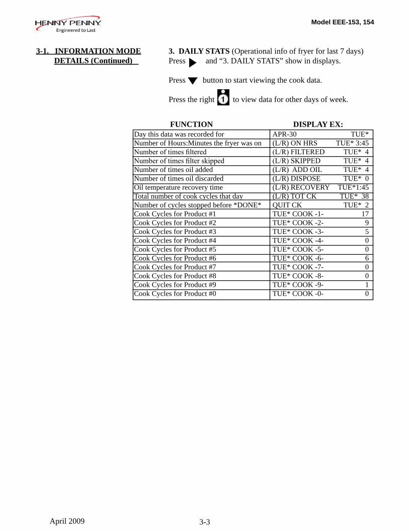
3. DAILY STATS (Operational info of fryer for last 7 days)Press and “3. DAILY STATS” show in displays.
Press button to start viewing the cook data.
Press the right to view data for other days of week.
Day this data was recorded for APR-30 TUE* Number of Hours:Minutes the fryer was on (L/R) ON HRS TUE* 3:45Numberoftimesfiltered (L/R)FILTERED TUE*4Numberoftimesfilterskipped (L/R)SKIPPED TUE*4Number of times oil added (L/R) ADD OIL TUE* 4Number of times oil discarded (L/R) DISPOSE TUE* 0Oil temperature recovery time (L/R) RECOVERY TUE*1:45Total number of cook cycles that day (L/R) TOT CK TUE* 38Number of cycles stopped before *DONE* QUIT CK TUE* 2Cook Cycles for Product #1 TUE* COOK -1- 17Cook Cycles for Product #2 TUE* COOK -2- 9Cook Cycles for Product #3 TUE* COOK -3- 5Cook Cycles for Product #4 TUE* COOK -4- 0 Cook Cycles for Product #5 TUE* COOK -5- 0Cook Cycles for Product #6 TUE* COOK -6- 6Cook Cycles for Product #7 TUE* COOK -7- 0Cook Cycles for Product #8 TUE* COOK -8- 0Cook Cycles for Product #9 TUE* COOK -9- 1Cook Cycles for Product #0 TUE* COOK -0- 0
FUNCTION DISPLAY EX:
April 2009
Model EEE-153, 154
3-4
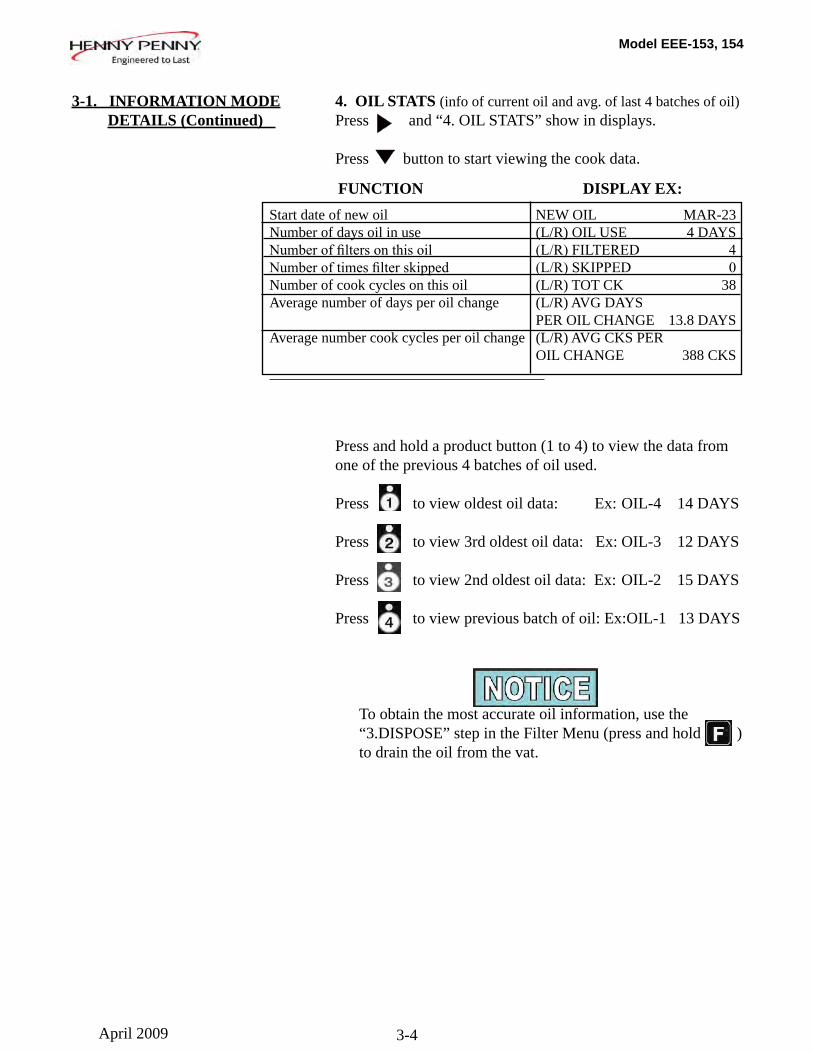
4. OIL STATS (info of current oil and avg. of last 4 batches of oil)Press and “4. OIL STATS” show in displays.
Press button to start viewing the cook data.
Press and hold a product button (1 to 4) to view the data from one of the previous 4 batches of oil used.
Press to view oldest oil data: Ex: OIL-4 14 DAYS
Press to view 3rd oldest oil data: Ex: OIL-3 12 DAYS
Press to view 2nd oldest oil data: Ex: OIL-2 15 DAYS
Press to view previous batch of oil: Ex:OIL-1 13 DAYS
To obtain the most accurate oil information, use the “3.DISPOSE” step in the Filter Menu (press and hold ) to drain the oil from the vat.
3-1. INFORMATION MODE DETAILS (Continued)
Start date of new oil NEW OIL MAR-23 Number of days oil in use (L/R) OIL USE 4 DAYSNumberoffiltersonthisoil (L/R)FILTERED 4Numberoftimesfilterskipped (L/R)SKIPPED 0Number of cook cycles on this oil (L/R) TOT CK 38Average number of days per oil change (L/R) AVG DAYS PER OIL CHANGE 13.8 DAYSAverage number cook cycles per oil change (L/R) AVG CKS PER OIL CHANGE 388 CKS
FUNCTION DISPLAY EX:
April 2009
Model EEE-153, 154
3-5
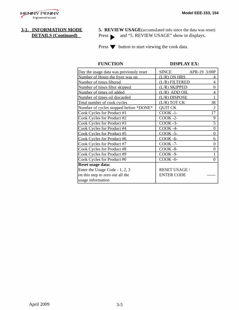
Day the usage data was previously reset SINCE APR-19 3:00PNumber of Hours the fryer was on (L/R) ON HRS 4Numberoftimesfiltered (L/R)FILTERED 4Numberoftimesfilterskipped (L/R)SKIPPED 0Number of times oil added (L/R) ADD OIL 4Number of times oil discarded (L/R) DISPOSE 1Total number of cook cycles (L/R) TOT CK 38Number of cycles stopped before *DONE* QUIT CK 2Cook Cycles for Product #1 COOK -1- 17Cook Cycles for Product #2 COOK -2- 9Cook Cycles for Product #3 COOK -3- 5Cook Cycles for Product #4 COOK -4- 0 Cook Cycles for Product #5 COOK -5- 0Cook Cycles for Product #6 COOK -6- 6Cook Cycles for Product #7 COOK -7- 0Cook Cycles for Product #8 COOK -8- 0Cook Cycles for Product #9 COOK -9- 1Cook Cycles for Product #0 COOK -0- 0Reset usage data: Enter the Usage Code - 1, 2, 3 RESET USAGE / on this step to zero out all the ENTER CODE ------usage information
5. REVIEW USAGE(accumulated info since the data was reset)Press and “5. REVIEW USAGE” show in displays.
Press button to start viewing the cook data.
FUNCTION DISPLAY EX:
3-1. INFORMATION MODE DETAILS (Continued)
April 2009
Model EEE-153, 154
3-6
6. INPUTSPress and “6. INPTS” and “HDE” show in displays.
H = HIGH LIMIT - If “H” is present, the high limit is good. If “-” shows then the high limit is tripped out (overheated) or discon- nected. D = DRAIN SWITCH - If “D” is present, the drain handle (when applicable) is closed. If “-” shows then the drain is open or the switch is faulty. E = ELEMENT SWITCH - If “E” is present, the element switch is good. If “-” shows in the display, the element is in the upright position, or the switch is faulty.
Press button and an underscore (“_”) indicates the input is not presently detected. A Checkmark (“√” ) indicates the signal is detecting a normal input. A blinking (“X”) indicates the signal is presently detected, but is detected as a half-wave (partially failed) input.
TheH,D,Esignalsabovearewiredinseries.Thefirstsignalmiss-ing out of this sequence l generally causes all signals to the right of it to be missing as well.
7. OUTPUTSPress and “7. OUPTS” and “S-H-” show in displays.
S = SAFETY CONTACTOR - Press to turn off and on the safety (primary) contactor H = HEAT CONTACTOR - Press to turn off and on the heat contactor.( turns off and on the safety (primary) contactor for the left vat of a split vat fryer, and turns off and on the heat contactor.)
8. OIL TEMPERATUREPress and “8.OIL TMP” shows in the left display and the oil temperature shows in the right display.
9. CPU TEMPERATUREPress and “9.CPU TMP” shows in the left display and the current PC board temperature shows in the right display.
3-1. INFORMATION MODE DETAILS (Continued)
April 2009

Model EEE-153, 154
4-1
This mode allows you to program the following:
1. Press and hold button until “PROG” shows in the display, followed by “ENTER CODE”.
2. Entercode1,2,3(first3productbuttons).“PRODUCT” and “PROGRAM” show in the displays, followed by “SELECT PRODUCT’ and “-P 1-” (ex: NUG).
Change Product Names3. Use the and buttons to scroll through the 40 products, or press the desired product button.
4. Press button and “NAME” shows in the left display and the product (ex: NUGGETS) shows in the right display.
5. Press √buttonandthefirstletterinthenameflashes.Press aproductbuttonandtheflashingletterchangestothefirst letter under the product button that was pressed. For exam- ple,if ispressed,theflashingletterchangestoan“A”.
Pressthesamebuttonagainandtheflashingletterchanges toa“B”.Pressitagainandtheflashingletterchangesto a “C”. Once the desired letter shows in the display, press button to continue to the next letter and repeat the procedure.
Press and hold the right X button to exit Program Mode, or press button to continue on to “COOK TIME”.
Assign Button6. Press button until “ASSIGN BTN” shows in the
display, along with the product (ex: NUGGETS). If this product already has a product button assigned to it, that LED will be lit. To assign other product buttons to that product, press and hold the product button for 3 seconds and that LED stays lit. To remove a product from a button, press and hold the product button with a lit LED and the LED goes out.
SECTION 4. PRODUCT PROGRAM MODE
4-1. MODIFYING PRODUCT SETTINGS
• Include in Filter Count (Global)• Filter at X no. of loads (Mixed)• Load Compensation • Load Compensation Reference• Full Heat• PC Factor
• Change Product Name• Assign Button• Change Times & Temp• Change Cook ID• Alarms• Quality Timers
April 2009
Model EEE-153, 154
4-2
To Change Times and Temperatures7. Press button until “COOK TIME” shows in the display, and then use the product buttons, or the and buttons, to change the time in minutes and seconds, to a maximum of 59:59.
8. Press button and “TEMP” shows in the display, along with the preset temperature on the right side of the display.
Press the product buttons, or the and buttons, to change the temperature. The temperature range is 190°F (88°C) to 375°F (191°C).
Cook ID Change9. Press button until “COOK ID” shows in the display
along with the product ID. For example, NUG would be the ID for nuggets. Use the product buttons, or the and buttons, to change the ID.
Alarms (1 & 2)11. Press button until “ALRM 1” shows in the left display, and an alarm time in the right display. Press the product buttons, or the and buttons, to set an alarm. Ex., If a Cook Cycle was set at 3 minutes, and an alarm was to go off after 30 seconds into the Cook Cycle, “2:30” would be set in the display at this time. When the timer counts down to 2:30 the alarm sounds.
After the alarm time is set, press button and “ALRM 2” shows in the display, and a second alarm can be programmed.
Quality Timer (hold time)12. Press button until “QUAL TMR” shows in the display
along with the preset holding time. Press the product buttons, or the and buttons,to adjust holding
time, up to 59:59.
Global Filter TrackingInclude in Filter Count 13a.Pressbuttonuntil“INCLINFLTRCNT”flashesin
the display along with “YES” or “NO”. Using and buttons, change the display to “YES” if that product’s Cook Cyclesaretobecountedaspartoftherecommendedfilterprocess. Set to “NO” if it is not to be included.
4-1. MODIFYING PRODUCT SETTINGS (Continued)
April 2009
Model EEE-153, 154
4-3
Mixed Filter TrackingFilter After X Number of Loads 13b.Pressbuttonuntil“FILTERAFTER...”flashes
in the left display along, and the number of cook cycles betweenfiltersshowsintherightdisplay.Presstheproductbuttons, or the and buttons, to change this value of 0 to 99 loads. This needs set for each product.
>Load Compensation, Load Compensation Reference, Full Heat, PC Factor< 14. Press button until “LD COMP” shows in the display,
along with the load compensation value. This automatical-ly adjusts the time to account for the size and temperature of the cooking load.
Press the product buttons, or the and buttons, to change this value of 0 to 20.
15. Press button until “LCMP REF” shows in the display along with the load compensation average temperature. (if load compensation is set to “OFF”, then “_ _ _” shows in display and setting cannot be programmed) This is the average cooking temperature for each product. The timer speeds up at temperatures above this setting and slows down at temperatures below this setting. Press the product button, or the and buttons, to change this value.
16. Press button until “FULL HT” shows in the display along with the full heat value in seconds, which means the heat is on as soon as a timer button is pressed, for the pro-grammed length of time. Press the product buttons, or the
and buttons, to change this value of 0 to 90 seconds.
17. Press button until “PC FACTR” shows in the display along with the proportional temperature, which helps to keep the oil from over-shooting the setpoint temperature. Press the product buttons, or the and buttons, to change this value of 0 to 50 degrees.
• Use button to go back to previous menu items. • Pressbuttonwhenfinishedwiththecurrentproduct,to return to the “SELECT PRODUCT” step. • Press and hold button to exit PRODUCT PROGRAM Mode.
4-1. MODIFYING PRODUCT SETTINGS (Continued)
April 2009
Model EEE-153, 154
5-1
SECTION 5. LEVEL 2 PROGRAMMING
The Special Program Mode is used to set more detailed programming, such as: SP-1 • Degrees Fahrenheit or CelsiusSP-2 • Language: English, Russian, Swedish (SVENSKT), German (DEUTSCHE), Portuguese, Spanish (ESPANOL) and French (FRANCAIS) SP-3 • System Initialization (Factory Presets)SP-4 • Audio VolumeSP-5 • Audio ToneSP-6 • Melt Cycle Select - 1.LIQUID; 2.SOLIDSP-7 • Idle Mode Enabled - YES or NOSP-7A • Use “0” for IDLESP-7B • Auto Idle MinutesSP-7C • Idle Set-point TemperatureSP-8 • Filter Tracking Mode - 1.MIXED or 2.GLOBALSP-8A • Suggest Filter At... - 75% to 100% (MIXED) SP-8B • Filter Lockout Enabled? - YES or NO (MIXED) SP-8A • Left Vat Filter Cycles - 0 to 99 (GLOBAL) SP-8B • Right Vat Filter Cycles - 0 to 99 (GLOBAL) SP-8C • Filter Lockout Enabled? - YES or NO (GLOBAL)SP-9 • Polish Duration - X:XX M:SSSP-10 • Change Pad Reminder Time - XX HRSSP-11 • Clean-Out Time - XX MINSP-12 • Clean-Out Temperature - XXX oF or oCSP-13 • Cooking User IO - After Cook Cycle, display shows revious menu item or “----”SP-14 • Number of Baskets - 2-BASKETS or 4 BASKETSSP-15 • Show Cooking Indicator - YES or NOSP-16 • 2nd Language: English, Russian, Swedish (SVENSKT), German (DEUTSCHE), Portuguese, Spanish (ESPANOL) and French (FRANCAIS) SP-17 • 2nd AudioVolumeSP-18 • Energy Save Enabled? - YES or NOSP-19 • Fryer Type - GAS or ELECTRICSP-20 • Vat Type - SPLIT or FULLSP-21 • Autolift Enabled? - NO LIFT or YES LIFTSP-22 • Bulk Oil Supply? - YES or NOSP-23 • Bulk Oil Dispose? - YES or NOSP-24 • Serial No. of FryerSP-25 • Change Mgr. Code- 1 = YESSP-26 • Change Usage Code - 1 = YESSP-27 • Dispose Requires Code ? - YES or NOSP-28 • Longer Fill Time Enabled - YES or NOSP-29 • Let User Exit Fill? - YES or NOSP-30 • Skip ‘SKIM’ Prompt? - YES or NOSP-31 • 2-Stage Wash Enabled? - YES or NO
5-1. SPECIAL PROGRAM MODE
Used to access the following: • Special Program Mode • Tech Mode • Clock Set • Stats • Data Communication • Filter Control • Heat Control
Nov. 2009
Model EEE-153, 154
5-2
Press and hold the button for 5 seconds until “LEVEL 2”followed by, “SP PROG” and “ENTER CODE” show in the display.
Enter code 1,2,3, and “SP-1”, “TEMP”, “FORMAT” show in the displays.
If a bad code is entered, a tone sounds and “BAD CODE” shows on the display. Wait a few seconds, the controls revert back to the cook mode, and repeat the above steps.
To exit from the Special Program Mode at any time, press and hold button for 2 seconds.
Degrees Fahrenheit or Celsius (SP-1) Theleftdisplayflashes“SP-1”and“TEMP”,“FORMAT”. Press the or buttons to choose ºF or ºC.
• Use button to go back to previous menu items
• PressbuttonwhenfinishedwiththecurrentLevel2 step
Language (SP-2) Press buttonand“SP-2”and“LANGUAGE”flashon the left display. Press the or buttons to select the desired language.
System Initialization (SP-3) Press button and “SP-3” and “DO SYSTEM INIT” flashinthedisplay,alongwith“INIT”ontherightdisplay. To reset the controls to factory default settings, press and hold √ button and control counts down “IN 3”, “IN2”, “IN 1”. Once display shows “-INIT-” & *DONE* the controls are reset to factory defaults.
Audio Volume (SP-4) Press buttonand“SP-4”and“VOLUME”flashinthe left display. Press the or , or use product buttons, to adjust the volume of the speaker, 10 being the maximum value and 1 the minimum.
5-1. SPECIAL PROGRAM MODE (Continued)
April 2009
Model EEE-153, 154
5-3
5-1. SPECIAL PROGRAM MODE (Continued)
Audio Tone (SP-5) Press buttonand“SP-5”and“TONE”flashinthe left display. Press the or , or use product buttons, to adjust the tone of the speaker, 2000 being the maximum value and 50 the minimum.
Liquid or Solid Cooking Oil Used (SP-6) Press button until “SP-6 MELT CYCLE SELECT” scrolls in the left display. Unless solid oil is being used in the vats the right display should show “1.LIQUID”.
If solid oil is used, the unit MUST BE equipped to handle solid oil. Use the and buttons to change the right display to “2.SOLID”
Idle Mode Enabled (SP-7)An Idle Mode allows the oil temperature to drop to a lower temperature when not in use. This savies on oil and utilities. Press button and “SP-7” and “IDLE MODE ENABLED?”flashintheleftdisplay.Presstheor buttons to choose YES” or “NO”.
With “YES” in the display, press button and “SP-7A” and“USE‘0’FORIDLE”flashontheleftdisplay.Press the or buttons to select “YES” or “NO”. If “YES” is selected, an Idle Mode can be programmed in product button .
Press button and “SP-7B” and “AUTOIDLE MINUTES”flashintheleftdisplay.Presstheor or use product buttons, to set the time (0 to 60 minutes) fryer stays idle before the auto-idle is enabled.
Ex.,“30” means, if product is not cooked in that vat for 30 minutes, the control automatically cools the oil down to the idle setpoint temperature
Press buttonand“SP-7C”and“IDLESETPT”flashin the left display. Press the or , or use product buttons, to set the idle temperature 200o to 375 oF (93 to 191 oC) .
April 2009
Model EEE-153, 154
5-4
Filter Tracking Mode (SP-8)FilterTrackingsignalstheoperatorwhentheoilneedsfilteringbycountingthenumberCookCyclesbetweenfilters. Press button and “SP-8” and “FILTER TRACKING MODE” show in the display. Use the and buttonstochooseeither“1.MIXED”filtertrackingor “2.GLOBAL”.
GLOBAL means all the products have the same number of cookcyclesbetweenfilters.
MIXED means each product may be set with different num- berofcookcyclesbetweenfilters.Thecontrolsaddsthe cycle counts (see example at left) and when the counts equal1orgreater,filteringissuggested.Ex:1loadoffish,2 loads of french fries, a load of chicken equals 1. 1/2 + 1/8 + 1/8 + 1/4 = 1.
MIXED If MIXED is selected, press button and “SP-8A” and “SUGGEST FILTER AT …” shows in the left display, and a value between 75% and 100% shows on the right display. Press the and buttons to change this value.
The lower the value, the sooner the control recommends to filter.Ex:Ifsetto75%,thecontrolsuggestfilteringafter 3/4 of the programmed cook cycles is met, whereas at 100%, all the cook cycles must be completed before the controlsuggestfiltering.
Press and “SP-8B” and “LOCKOUT ENABLED?” shows in the left display. Press the and buttons to choose YES or NO.
IfsettoYES,whenthecontrolssuggestfiltering,“FILTER LOCKOUT”/”YOU *MUST* FILTER NOW”, shows in the display, and it refuses further cook cycles until the vat is filtered.
Press and “SP-8C” and “LOCKOUT AT...” shows in the left display and a value between 100% and 250% shows on the right display. Press the and buttons to change this value. The lower the value, the sooner the “lockout” occurs.
Ex: If set at 100%, “lockout” occurs when the cycle counts reaches 1 or greater. Set at 200%, twice as many cycles are counted before “lockout” occurs. See example above.
5-1. SPECIAL PROGRAM MODE (Continued)
No. Cook CycleProduct Cycles CountFish 2 1/2French Fries 8 1/8Chicken 4 1/4
April 2009
Model EEE-153, 154
5-5
5-1. SPECIAL PROGRAM MODE (Continued)
Filter Tracking Mode (SP-8) (Continued) GLOBAL If GLOBAL is selected, press button.
Split Vat If unit is a split vat, “SP-8A” and “LEFT VAT FILTER CYCLES” shows in the left display, and the number of cook cyclesbetweenfiltersshowsontherightdisplay(0to99). Use and to change this number.
Press button and “SP-8B” and “RIGHT VAT FILTER CYCLES” shows in the left display, and the number of cook cyclesbetweenfiltersshowsontherightdisplay(0to99).
Press button and “SP-8C” and “LOCKOUT ENABLED? shows in the left display. Press the and buttons to choose YES or NO.
IfsettoYES,whenthecontrolssuggestfiltering,“FILTER LOCKOUT”/”YOU *MUST* FILTER NOW”, shows in the display, and it refuses further cook cycles until the vat is filtered.
Full Vat If unit is a full vat, “SP-8A” and “FULL VAT FILTER CYCLES” shows in the left display, and the number of cook cyclesbetweenfiltersshowsontherightdisplay(0to99). Use and to change this number.
Press button and “SP-8C” and “LOCKOUT ENABLED?” shows in the left display. Press the and buttons to choose YES or NO.
IfsettoYES,whenthecontrolssuggestfiltering,“FILTER LOCKOUT”/”YOU *MUST* FILTER NOW”, shows in the display, and it refuses further cook cycles until the vat is filtered.
April 2009
Model EEE-153, 154
5-6
5-1. SPECIAL PROGRAM MODE (Continued)
Polish Duration (SP-9) Press buttonand“SP-9POLISHTIME”flashesin the left display. Press the or , or use product buttons, to change polish time, from 0 to 10 minutes.
Change Filter Pad Reminder Time (SP-10) Press button and “SP-10 CHANGE PAD’ REMINDER” flashesintheleftdisplay.Presstheor,or use product buttons, to change the time from 0 to 100 hours.
Clean-Out Time (SP-11) Press buttonand“SP-11CLEAN-OUTTIME”flashes in left display. Press the or , or use product buttons, to change the time from 0 to 99 minutes.
Clean-Out Temperature (SP-12) Press buttonand“SP-12CLEAN-OUTTEMP”flashes in the left display. Press the or , or use product buttons, to change the temperature from 0 to 195o F (90o C).
Cooking User IO (SP-13) Press button and “SP-13 COOKING USER IO” flashesinthedisplay.Presstheor buttons to choose “SHOWPREV” or “SHOW----”.
Setting SP-13 to SHOWPREV means after a cook cycle the display shows the last menu item cooked. SHOW---- means after a cook cycle “----” shows in the display and a menu item needs selected before starting the next cook cycle.
Number of Baskets (SP-14) Press button and “SP-14 NUMBER OF BASKETS” flashesintheleftdisplay.Presstheorbuttonsto choose 2 or 4 baskets per well.
Cooking Indicator (SP-15) Press button and “SP-15 SHOW COOKING INDICATOR”flashesintheleftdisplay.Presstheor buttons to choose YES, and during a cook cycle, “*” shows which timer is counting-down. Choose NO and “*” will not show during a cook cycle.
Sept. 2011
Model EEE-153, 154
5-7
5-1. SPECIAL PROGRAM MODE (Continued)
2nd Language (SP-16) Press buttonand“SP-162NDLANGUAGE”flashes on the left display. Press the or buttons to select the desired 2nd language.
By setting a 2nd language in the controls, 2 languages can now be chosen by pressing button during normal operation.
One language shows in the left display and the second language shows in the right display. Pressing the ü button selects the language in the displays.
2nd Volume (SP-17) Press buttonand“SP-172NDVOLUME”flashes on the left display. Press the or buttons, or the product buttons to select the desired 2nd volume.
By setting a 2nd volume in the controls, 2 volumes can now be chosen by pressing button twice during normal operation.
One volume setting shows in the left display (NONE to 10; 10 being the loudest) and the second volume shows in the right display. To select the volume, press the ü button under the desired volume .
Engery Save Mode (SP-18) Press button and “SP-18 ENERGY SAVE EN- ABLED?”flashesintheleftdisplay.Presstheor buttons to choose “YES” or “NO”.
If set to YES, during times of non-use the fryer automati- cally starts an Energy Save Mode, which turns-off the blowers. Then once a product is selected to start a cook cycle, the blowers and heat come back on. If set to NO, the blowers are on constantly.
Fryer Type (SP-19) Press buttonand“SP-19FRYERTYPE”flashesin the left display. Press the or buttons to choose “GAS” or “ELEC”.
Vat Type (SP-20) Press buttonand“SP-20VATTYPE”flashesinthe left display. Press the or buttons to choose “SPLIT” or “FULL”.
Sept. 2011
Model EEE-153, 154
5-8
5-1. SPECIAL PROGRAM MODE (Continued)
Autolift Enabled (SP-21) Press button and “SP-21 AUTOLIFT ENABLED?” flashesintheleftdisplay.Presstheorbuttons to choose “YES LIFT” or “NO LIFT”.
Iffryerisfittedwiththeauto-liftoption,SP-21mustbeset to “YES LIFT”, otherwise, set SP-21 to “NO LIFT”.
Bulk Oil Supply (SP-22) Press button and “SP-22 BULK OIL SUPPLY?” flashesintheleftdisplay.Presstheorbuttons to choose “YES SUPL” or “NO SUPL”.
Set to YES if the oil is pumped into the vats from an outside oil reservoir. Otherwise, set SP-22 to NO.
Bulk Oil Disposal (SP-23) Press button and “SP-23 BULK OIL DISPOSE?” flashesintheleftdisplay.Presstheorbuttons to choose “YES DISP” or “NO DISP”.
Set to “YES DISP” if the oil is pumped from the vats to an outside oil reservoir when disarding the oil. Otherwise, set SP-23 to “NO DISP”.
Serial Number Log (SP-24) Press button and “SP-24 S/N üEDIT”flashesinthe displays, along with the serial number of the unit. THIS SERIAL NUMBER SHOULD MATCH THE SERIAL NUMBER ON THE DATA PLATE, ON THE DOORS. IF NOT, IT CAN BE RECORDED.
Program Code Change (SP-25)This allows the operator to change the program code (factory set at 1, 2, 3) used to access Product Programming and Level 2 Program Mode. Press button and “SP-25 CHANGE MGR CODE? 1=YES”flashinthedisplay.Press and“ENTER NEW CODE, P=DONE, I=QUIT show scrolls through the display. Press the product buttons for new code.
Ifsatisfiedwithcode,pressand“REPEATNEW CODE, P=DONE, I=QUIT, shows in display. Press same code buttons.
Sept. 2011
Model EEE-153, 154
5-9
5-1. SPECIAL PROGRAM MODE (Continued)
Program Code Change (SP-25) (Continued) Ifsatisfiedwithcode,pressand“*CODE CHANGED*” shows in display.
Ifnotsatisfiedwithcode,pressand“*CANCEL” shows in display, then reverts back to “SP-25” and “CHANGE, MGR CODE? 1=YES”. Now the above steps can be repeated.
Usage Code Change (SP-26)This allows the operator to change the reset usage code (factory set at 1, 2, 3) to reset the usage amounts of each product. See Review Usage step in Information Mode. Press button and “SP-26 CHANGE USAGE CODE?1=YES”flashesinthedisplay.Press and “ENTER NEW CODE, P=DONE, I=QUIT show scrolls through display. Press product buttons for new code.
Ifsatisfiedwithcode,pressand“REPEATNEW CODE, P=DONE, I=QUIT, shows in display. Press same code buttons.
Ifsatisfiedwithcode,press“*CODECHANGED*” shows in display.
Ifnotsatisfiedwithcode,pressand“*CANCEL” shows in display, then reverts back to “SP-26” and “CHANGE, USAGE CODE? 1=YES”. Now the above steps can be repeated.
Dispose Requires Code ? (SP-27) Press button and “SP-27 DISPOSE REQUIRES CODE?”flashesintheleftdisplay.Presstheor buttons to choose YES or NO. If set to YES, code 1, 2, 3 must be entered to discard the oil from the vat, using the Dispose Mode.
Longer Fill Time (SP-28) Press button and “SP-28 LONGER FILLTIME ENABLED?”flashesintheleftdisplay.Presstheor buttons to choose YES or NO.
Let User Exit Fill (SP-29) Press button and “SP-29 LET USER EXIT FILL” flashesintheleftdisplay.Presstheor buttons to choose YES or NO. If YES is chosen, the user can exit the Express FilterTM fill operation.
Sept. 2011
Model EEE-153, 154
5-10
5-1. SPECIAL PROGRAM MODE (Continued)
Skip ‘SKIM’ Prompt (SP-30) Press button and “SP-30 SKIP ‘SKIM’ PROMPT?” flashesintheleftdisplay.Presstheorbuttonsto choose YES or NO.
2-Stage Wash Enabled (SP-31) Press button; “SP-31 2-STAGE WASH ENABLED?” flashesintheleftdisplay.Presstheorbuttonsto choose YES or NO.
Time periods of peak operations during which the “FILTER NOW?” message will not appear, may be programmed into the fryer. There are three groupings of days - Monday thru Friday (M-F), Saturday (SAT), and Sunday (SUN). Within each day grouping, up to 4 time periods (M-F 1 thru M-F 4, SAT 1 thru SAT 4, and SUN 1 thru SUN 4) may be programmed. A time period may be anywhere from 1 to 180 minutes in length.
1. Press and hold the button for 5 seconds until “LEVEL 2”, followed by, “SP PROG” and “ENTER CODE” show in the display.
2. Press button once more and “DO NOT DISTURB” and“ENTERCODE”flashintheleftdisplay.
3. Entercode1,2,3(first3productbuttons). 4. “DONOTDISTURBENABLED?”flashesintheleft display and YES or NO appears in the right display. Press the or buttons to choose YES or NO..5. Press button and “M-F 1” shows in the left display andthetimeflashesintherightdisplay.Pressthe or , or use product buttons, to change the time.
6. Press button and “M-F 1” shows in the left display and“A”or“P”flashesintherightdisplay.Usethe or buttons to choose AM or PM.
7. Press button and “M-F 1” shows in left display and far rightcharacterdisplayflashes.Pressproductbuttonsto enter amount of time (up to 180 minutes) during which filteringwillbeinhibited,aftertimeenteredinstep5.
8. Press button to move to the next timer period, M-F 2.
9. Repeat steps 5, 6, 7, and 8 for other desired time periods.
5-2. DO NOT DISTURB
Sept. 2011
Model EEE-153, 154
5-11
5-3. CLOCK SET 1. Press and hold the button for 5 seconds until “LEVEL 2”, followed by, “SP PROG” and “ENTER CODE” show in the display.
2. Press the button again and “CLK SET” and “ENTER CODE”flashintheleftdisplay.
3. Entercode1,2,3(first3productbuttons). 4. “CS-1ENTERDATEMM-DD-YY”flashesintheleft display. Use the product buttons to set the date in the right display.
5. Pressbuttonand“CS-2ENTERTIME”flashesinthe leftdisplayandthetimeflashesintherightdisplay.Press the or , or use product buttons, to change the time.
6. Pressbuttonand“CS-2ENTERTIME”flashesinthe leftdisplayand“AM”or“PM”flashesintherightdisplay. Use the or buttons to choose AM or PM.
7. Pressbuttonand“CS-3TIMEFORMAT”flashesin the left display and “12-HR” or “24-HR” shows in the right display. Use the or buttons to choose a 12 hour time format or a 24 hour time format.
8. Press button and “CS-4 DAYLIGHT SAVING TIME” flashesintheleftdisplay.Usethe orbuttons to choose daylight saving time for your area: 1.OFF; 2.US (2007 & after); 3.EURO; or 4.FSA (US before 2007).
The Data Logging, Heat Control, Tech, Stat and Filter Control Modes are advanced diagnostic and program modes, mainly for Henny Penny use only. For more information on these modes, contact the Service Department at 1-800-417- 8405 or 1-937-456-8405.
5-4. DATA LOGGING, HEAT CONTROL, TECH, STAT, AND FILTER CONTROL MODES
Sept. 2011
Model EEE-153, 154
5-12
5-5. TECH MODE The TECH Mode has self-diagnostic information, which can be usedbycertifiedtechniciansfortroubleshootingpurposes,suchas:
T-1 • SoftwareT-2 • Fryer Type (Gas or Elec.) T-3 • Push Button TestT-4 • All On Display TestT-5 • Display Segment TestT-6 • Display Digits TestT-7 • Display Decimal Point TestT-8 • LED’s TestT-9 • Left Temp. Probe Calibration & OffsetT-10 • Left Level 1 Probe Calibration & OffsetT-11 • Left Level 2 Probe Calibration & OffsetT-12 • Right Temp. Probe Calibration & OffsetT-13 • Right Level 1 Probe Calibration & OffsetT-14 • Right Level 2 Probe Calibration & OffsetT-15 • CPU Control Temp. Calibration/Offset/HighestT-16 • View A - D ChannelT-17 • Digital Inputs T-18 • AIF InfoT-19 • Outputs TestT-20 • Pumps & Valves TestT-21 • Recovery Test LimitT-22 • Drain Light Stay On?T-23 • Heat Err Enabled?T-24 • Change Tech Code?T-25 • Total Initialization
Not all Tech Mode functions are discussed in this section. To ensure proper operation of fryer, please consult Henny Penny Corp. before changing any of these settings. For more information on these functions, contact the Service Department at 1-800-417- 8405, or 1-937-456-8405.
April 2009
Model EEE-153, 154
5-13
5-5. TECH MODE (Continued) 1. Press and hold the button for 5 seconds until “LEVEL 2”, followed by, “SP PROG” and “ENTER CODE” show in the display.
2. Press the button 4 times and “TECH” and “ENTER CODE”flashintheleftdisplay.
3. Entercode1,1,2,2,1,1,2,2(first2productbuttons). 4. “T-1SOFTWARE”flashesintheleftdisplayand “EV-ELITE” shows in the right display. Use the and buttons to select the steps.
If a bad code is entered, a tone sounds and “BAD CODE” shows on the display. Wait a few seconds, the controls revert back to the cook mode, and repeat the above steps.
Press and hold button at anytime to return to normal operation.
T-1 - SOFTWARE • Press to view HP Part No. of eprom
• Press to view software ID
• Press to view software version
T-2 - FRYER TYPE - GAS or ELEC
T-3 - PUSH-BUTTON TESTPress any of the control buttons to test operation. You should hear a beep, and the LED should light and/or a display.
T-4 - ALL ON DISPLAY TESTPress any of the product buttons and all the LEDs and display segments should light.
T-5 - SEGMENTS TESTPress button to view the different segments of the display
characters.
T-6 - DIGITS TESTPress button to view all segments of each digit across the
displays.
April 2009
Model EEE-153, 154
5-14
5-5. TECH MODE (Continued) T-7 - DECIMAL PTS TESTPress button to view all decimal points across the displays.
T-8 - LED’S TESTPress buttons to view each LED across the control panel.
T-17 - DIGITAL INPUTS - HDEH = HIGH LIMIT - If “H” is present, the high limit is good. If “-” shows then the high limit is tripped out (overheated) or discon- nected. D = DRAIN SWITCH - If “D” is present, the drain handle (when applicable) is closed. If “-” shows then the drain is open or the switch is faulty. E = ELEMENT SWITCH - If “E” is present, the element switch is good. If “-” shows in the display, the element is in the upright position, or the switch is faulty.
Press button and an underscore (“_”) indicates the input is not presently detected. A Checkmark (“ü” ) indicates the signal is detecting a normal input. A blinking (“X”) indicates the signal is presently detected, but is detected as a half-wave (partially failed) input.
TheH,D,Esignalsabovearewiredinseries.Thefirstsignalmiss-ing out of this sequence l generally causes all signals to the right of it to be missing as well.
T-18 - AIF INFO (AIF PCB communicating with control PCB?)An “AIF ü ” means normal communications between the AIF PCB and the control PCB. “AIF X” means a problem with the communications between the PCBs.
T-19 - OUTPUTSS = SAFETY CONTACTOR - Press to turn off and on the safety (primary) contactor H = HEAT CONTACTOR - Press to turn off and on the heat contactor.( turns off and on the safety (primary) contactor for the left vat of a split vat fryer, and turns off and on the heat contactor.)
April 2009
Model EEE-153, 154
5-15
5-5. TECH MODE (Continued) T-20 - PUMPS & VALVES Press button and “LIGHTS” “DLT_” shows in displays.
Press and left Filter Beacon® lights (split vats) and pressbutton and right Filter Beacon® lights (display shows “DLTo” when on)
Press button and “VALVES” “DcRc” shows in displays.
Press to open and close the return valve.
“DcRc” means valve is closed, “DcRo” means valve is open. (Driven by the control board)
Press button and “DISCARDc” and “JIBFILLc” shows in the displays. (Driven by the AIF board)
Press to open and close the RTI discard valve (display shows “DISCARDo” when open)
PresstoopenandclosetheRTIJIBfillvalve(displayshows “JIBFILLo” when open)
Press button and “PUMP FP_” and “JP_ NP_” shows in the displays. (Driven by the AIF board)
Presstoturnoffandonthefilterpump(displayshows“FP*” when on)
Press to turn off and on the JIB pump (display shows “JP*” when on)
Press to turn off and on the new oil pump (if available - display shows “NP*” when on)
April 2009
Model EEE-153, 154
5-16
5-5. TECH MODE (Continued) Press button and “AIF REQ” and “RQ=Y OK=Y” shows in the displays.
REQ=Y” means that this particular control is currently request-ing control of the AIF Board outputs.
“OK=Y” means that the AIF Board has granted this control the authority to control the AIF Board outputs.
Press button and “FILR IN” and “USE BY 1(ex)” shows in the displays. These displays shows which controls are using thefilteringsystem.
“USE = 0” = not in use“USE = 7” = used by AIF“USE = 1 to 5” = used by control PCB
Press button and “CPU POSN” and “1 OF 3(ex)” shows in the displays. These displays shows which controls are plugged into which port on the AIF board.
For example, the left control should be plugged into port 1, and on a 3 control fryer, shows “1 OF 3” on the display.
If the right control is unplugged, then the left control would show “1 OF 2” instead of “1 OF 3”.
Press button and “INP E_P_” and “JL_Rx DF_” shows in the displays.
AIF Board Inputs:E = Stop button Ex = E-Stop pressed.P = Drain Pan Px = drain pan is missing.JL = JIB Jx = JIB oil level is low.R = RTI Rx = RTI System NOT DetectedDT = Discard Tank DTx = tank full
April 2009
Model EEE-153, 154
5-17
5-5. TECH MODE (Continued) Press button and “OUT F_J_” and “N_DI_oJF_” shows in the displays.
AIF Board Outputs:Current outputs status from AIF board.F = Filter Pump. (Fx = Filter pump is on)J = JIB Pump. (Jx = JIB pump is on)N = New Oil Pump. (Nx = RTI new oil pump on)(if present)DI = Discard Valve. (DIo = Disc. valve open/DIc=closed)(if present)JF=JIBFillValve. (JFo=JIBfillvalveopen/JFc=closed)
Press button and “REQ F_J_” and “N_DI_JF_” shows in the displays.
AIF Board Outputs Requested by the Control Board:Current outputs status from AIF board.F = Filter Pump. (Fx = Filter pump is on)J = JIB Pump. (Jx = JIB pump is on)N = New Oil Pump. (Nx = New oil pump on)(if present)DI = Discard Valve. (DIo = Disc. valve open/DIc=closed)(if present)JF=JIBFillValve. (JFo=RTIJIBfillvalveopen/JFc=closed)
April 2009
Model EEE-153, 154
5-18
5-6. STATS MODE This mode allows a technician to view advanced information on the operation of the fryer and controls.
1. Press and hold the button for 5 seconds until “LEVEL 2”, followed by, “SP PROG” and “ENTER CODE” show in the display.
2. Press the button 5 times and “STATS” and “ENTER CODE”flashintheleftdisplay.
3. Entercode1,1,2,2,1,1,2,2(first2productbuttons). 4. “ST-1STATSLASTRESETON...”flashesintheleft display and the date shows in the right display. Use the and buttons to select the steps.
If a bad code is entered, a tone sounds and “BAD CODE” shows on the display. Wait a few seconds, the controls revert back to the cook mode, and repeat the above steps.
Press and hold button at anytime to return to normal operation.
ST-1 • Stats Last Reset DateST-2 • Fryer Total Running Hours ST-3 • Left Vat Melt Cycle HoursST-4 • Left Vat Cook Cycle HoursST-5 • Left Vat Idle HoursST-6 • Right Vat Melt Cycle HoursST-7 • Right Vat Cook Cycle HoursST-8 • Right Vat Idle HoursST-9 • Power-Ups CountST-10 • Error CountsST-11 • Left Vat Heat On HoursST-12 • Right Vat Heat On HoursST-13 • Highest Left Vat Oil TemperatureST-14 • Highest Right Vat Oil TemperatureST-15 • Highest CPU Temperature
ST-16 • System RAM Fade CountST-17 • Cook RAM Fade CountST-18 • Product RAM Fade CountST-19 • Stat RAM Fade CountST-20 • RAM Data Error CountST-21 • Data Total Loss CountST-22 • User Intialization CountST-23 • Automatic Initialization CountST-24 • Cooks Count per ProductST-25 • Cook Cycle Stop Counts -“A”=numberofstopsinfirst30seconds - “B” = 0 - “C” = 0 - “D” = complete cook cycles countedST-26 • Reset All Stats
April 2009
Model EEE-153, 154
6-1
This section provides checkout and replacement procedures, for various parts of the fryer. Before replacing any parts, refer totheTroubleshootingSectiontoaidyouinfindingthecauseof the malfunction.
1. A multimeter will help you to check the electric components.
2. When the manual refers to the circuit being closed, the multimeter should read zero unless otherwise noted.
3. When the manual refers to the circuit being open, the multimetershouldreadinfinity.
Donotmovethefryerwithhotoilinthevatorfilter pan. Severe burns can result from splashing hot oil.
To ensure a long life of the fryers and their components, regular maintenance should be performed. Refer to the chart below.Frequency Action Daily Filter the oil (See Daily Filtering Instructions Section in Operator’s Manual)
Daily Change Filter Pad (See Changing Filter Pad Section in Operator’s Manual)
Everyfilterpadchange Lubricatefilterpano-rings Quarterly Inspect/Change Filter Pan O-Rings (See Check/Replace Filter Drain Pan O-Ring Section)
When oil smokes, Change oilfoams-upviolently, or tastes bad
Every change of oil Clean Vat (See Clean-Out Mode Section in Operator’s Manual)
SECTION 6. MAINTENANCE
6-1. INTRODUCTION
6-2. MAINTENANCE HINTS
6-3. PREVENTIVE MAINTENANCE
April 2009
Model EEE-153, 154
6-2
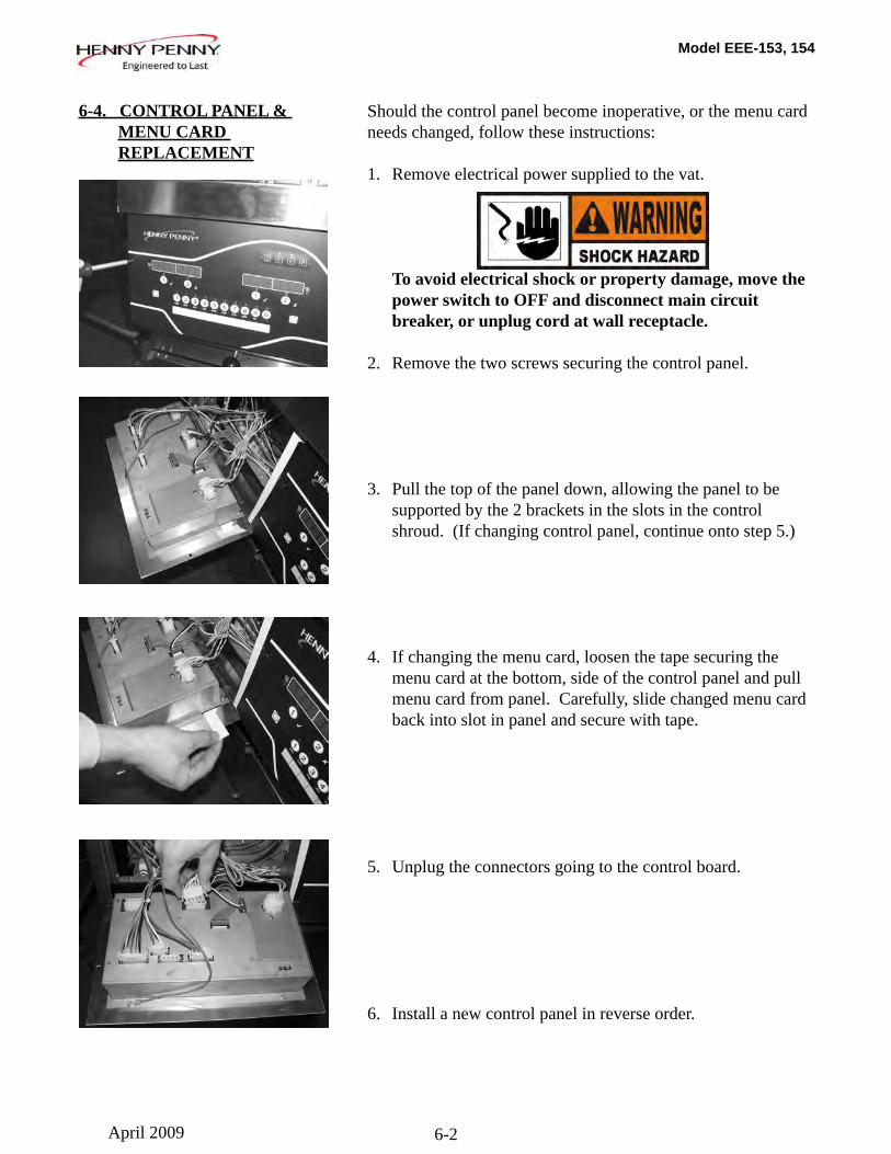
Should the control panel become inoperative, or the menu card needs changed, follow these instructions:
1. Remove electrical power supplied to the vat.
To avoid electrical shock or property damage, move the power switch to OFF and disconnect main circuit breaker, or unplug cord at wall receptacle. 2. Remove the two screws securing the control panel.
3. Pull the top of the panel down, allowing the panel to be supported by the 2 brackets in the slots in the control shroud. (If changing control panel, continue onto step 5.)
4. If changing the menu card, loosen the tape securing the menu card at the bottom, side of the control panel and pull menu card from panel. Carefully, slide changed menu card back into slot in panel and secure with tape.
5. Unplug the connectors going to the control board.
6. Install a new control panel in reverse order.
6-4. CONTROL PANEL & MENU CARD REPLACEMENT
April 2009
Model EEE-153, 154
6-3
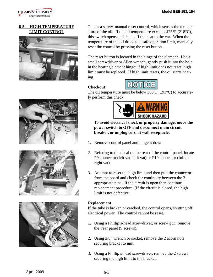
This is a safety, manual reset control, which senses the temper-ature of the oil. If the oil temperature exceeds 425°F (218°C), this switch opens and shuts off the heat to the vat. When the temperature of the oil drops to a safe operation limit, manually reset the control by pressing the reset button.
The reset button is located in the hinge of the element. Use a small screwdriver or Allen wrench, gently push it into the hole in the heating element hinge; if high limit does not reset, high limit must be replaced. If high limit resets, the oil starts heat-ing.
Checkout:The oil temperature must be below 380°F (193°C) to accurate-ly perform this check.
To avoid electrical shock or property damage, move the power switch to OFF and disconnect main circuit breaker, or unplug cord at wall receptacle.
1. Remove control panel and hinge it down.
2. Refering to the decal on the rear of the control panel, locate P9 connector (left vat-split vat) or P10 connector (full or right vat).
3. Attempt to reset the high limit and then pull the connector from the board and check for continuity between the 2 appropriate pins. If the circuit is open then continue replacement procedure. (If the circuit is closed, the high limit is not defective.
ReplacementIf the tube is broken or cracked, the control opens, shutting off electrical power. The control cannot be reset.
1. Using a Phillip’s-head screwdriver, or screw gun, remove the rear panel (9 screws).
2. Using 3/8” wrench or socket, remove the 2 acorn nuts securing bracket to unit.
3. Using a Phillip’s-head screwdriver, remove the 2 screws securing the high limit to the bracket.
6-5. HIGH TEMPERATURE LIMIT CONTROL
April 2009

Model EEE-153, 154
6-4
Replacement (continued)
4. Use the lift tool and lift the hinged element from the vat.
Avoid putting the lift tool in the center of the elements, at the same area as the high limit bulb, or damage to the high limit could result.
5. Pull the high limit from the bracket, pull back the cardboard protector, and remove the two electrical wires from the high limit control.
6. Pull-out on the drain valve knob and drain the oil from the vat.
7. While holding the top-side capillary bracket, use a Phillip’s-head screwdriver and remove the screws securing the capillary bulb to the lower element bracket. Remove both front and rear capillary brackets.
6-5. HIGH TEMPERATURE LIMIT CONTROL (Continued)
April 2009
Model EEE-153, 154
6-5
6-5. HIGH TEMPERATURE LIMIT CONTROL (Continued)
Replacement (continued)
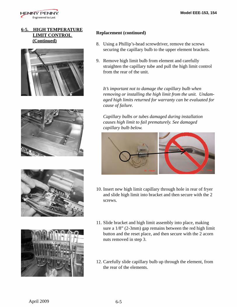
8. Using a Phillip’s-head screwdriver, remove the screws securing the capillary bulb to the upper element brackets.
9. Remove high limit bulb from element and carefully straighten the capillary tube and pull the high limit control from the rear of the unit.
It’s important not to damage the capillary bulb when removing or installing the high limit from the unit. Undam- aged high limits returned for warranty can be evaluated for cause of failure.
Capillary bulbs or tubes damaged during installation causes high limit to fail prematurely. See damaged capillary bulb below.
10. Insert new high limit capillary through hole in rear of fryer and slide high limit into bracket and then secure with the 2 screws.
11. Slide bracket and high limit assembly into place, making sure a 1/8” (2-3mm) gap remains between the red high limit button and the reset place, and then secure with the 2 acorn nuts removed in step 3.
12. Carefully slide capillary bulb up through the element, from the rear of the elements.
April 2009
Model EEE-153, 154
6-6
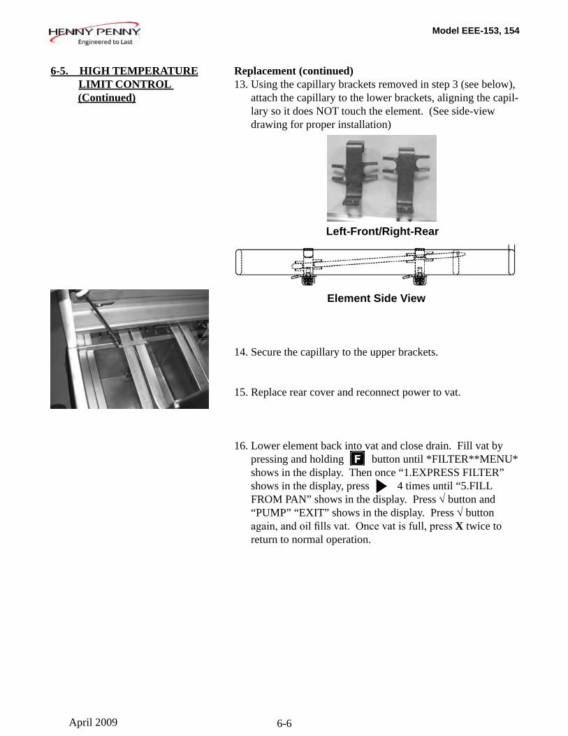
Replacement (continued)13. Using the capillary brackets removed in step 3 (see below), attach the capillary to the lower brackets, aligning the capil- lary so it does NOT touch the element. (See side-view drawing for proper installation)
Left-Front/Right-Rear
Element Side View
14. Secure the capillary to the upper brackets.
15. Replace rear cover and reconnect power to vat.
16. Lower element back into vat and close drain. Fill vat by pressing and holding button until *FILTER**MENU* shows in the display. Then once “1.EXPRESS FILTER” shows in the display, press 4 times until “5.FILL FROM PAN” shows in the display. Press √ button and “PUMP” “EXIT” shows in the display. Press √ button again,andoilfillsvat.Oncevatisfull,pressX twice to return to normal operation.
6-5. HIGH TEMPERATURE LIMIT CONTROL (Continued)
April 2009
Model EEE-153, 154
6-7
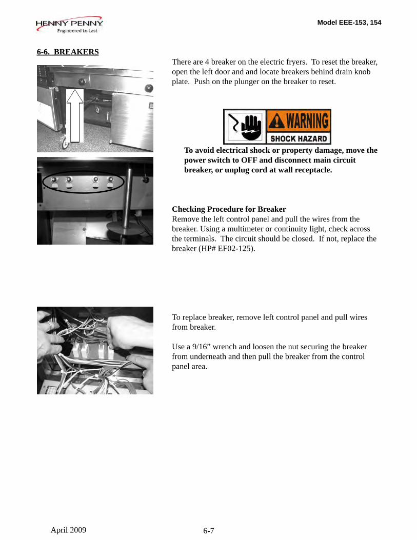
There are 4 breaker on the electric fryers. To reset the breaker, open the left door and and locate breakers behind drain knob plate. Push on the plunger on the breaker to reset.
To avoid electrical shock or property damage, move the power switch to OFF and disconnect main circuit breaker, or unplug cord at wall receptacle.
Checking Procedure for BreakerRemove the left control panel and pull the wires from the breaker. Using a multimeter or continuity light, check across the terminals. The circuit should be closed. If not, replace the breaker (HP# EF02-125).
To replace breaker, remove left control panel and pull wires from breaker.
Use a 9/16” wrench and loosen the nut securing the breaker from underneath and then pull the breaker from the control panel area.
6-6. BREAKERS
April 2009
Model EEE-153, 154
6-8
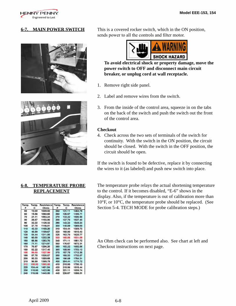
This is a covered rocker switch, which in the ON position, sendspowertoallthecontrolsandfiltermotor.
To avoid electrical shock or property damage, move the power switch to OFF and disconnect main circuit breaker, or unplug cord at wall receptacle. 1. Remove right side panel.
2. Label and remove wires from the switch.
3. From the inside of the control area, squeeze in on the tabs on the back of the switch and push the switch out the front of the control area.
Checkout4. Check across the two sets of terminals of the switch for continuity. With the switch in the ON position, the circuit should be closed. With the switch in the OFF position, the circuit should be open.
If the switch is found to be defective, replace it by connecting the wires to it (as labeled) and push new switch into place.
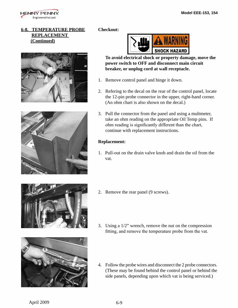
The temperature probe relays the actual shortening temperature to the control. If it becomes disabled, “E-6” shows in the display. Also, if the temperature is out of calibration more than 10°F, or 10°C, the temperature probe should be replaced. (See Section 5-4. TECH MODE for probe calibration steps.)
An Ohm check can be performed also. See chart at left and Checkout instructions on next page.
6-7. MAIN POWER SWITCH
6-8. TEMPERATURE PROBE REPLACEMENT
April 2009
Model EEE-153, 154
6-9
Checkout:
To avoid electrical shock or property damage, move the power switch to OFF and disconnect main circuit breaker, or unplug cord at wall receptacle.
1. Remove control panel and hinge it down.
2. Refering to the decal on the rear of the control panel, locate the 12-pin probe connector in the upper, right-hand corner. (An ohm chart is also shown on the decal.)
3. Pull the connector from the panel and using a multmeter, take an ohm reading on the appropriate Oil Temp pins. If ohmreadingissignificantlydifferentthanthechart, continue with replacement instructions.
Replacement:
1. Pull-out on the drain valve knob and drain the oil from the vat.
2. Remove the rear panel (9 screws).
3. Using a 1/2” wrench, remove the nut on the compression fitting,andremovethetemperatureprobefromthevat.
4. Follow the probe wires and disconnect the 2 probe connectors. (These may be found behind the control panel or behind the side panels, depending upon which vat is being serviced.)
6-8. TEMPERATURE PROBE REPLACEMENT (Continued)
April 2009
Model EEE-153, 154
6-10
6-9. OIL CHANNEL CLEAN-OUT
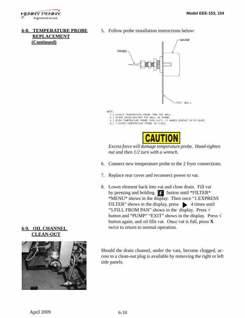
5. Follow probe installation instructions below:
Excess force will damage temperature probe. Hand-tighten nut and then 1/2 turn with a wrench.
6. Connect new temperature probe to the 2 fryer connections.
7. Replace rear cover and reconnect power to vat.
8. Lower element back into vat and close drain. Fill vat by pressing and holding button until *FILTER* *MENU* shows in the display. Then once “1.EXPRESS FILTER” shows in the display, press 4 times until “5.FILL FROM PAN” shows in the display. Press √ button and “PUMP” “EXIT” shows in the display. Press √ buttonagain,andoilfillsvat.Oncevatisfull,pressX twice to return to normal operation.
Should the drain channel, under the vats, become clogged, ac-cess to a clean-out plug is available by removing the right or left side panels.
6-8. TEMPERATURE PROBE REPLACEMENT (Continued)
April 2009
Model EEE-153, 154
6-11
This switch cuts power to the element when the element is raised.
If a constant “E-31” “HEATING ELEMENTS ARE UP”, is shown on the display, when the elements are lowered into the vat, check the element safety switch.
To avoid electrical shock or property damage, move the power switch to OFF and disconnect main circuit breaker, or unplug cord at wall receptacle.
Checkout:1. Remove control panel and hinge it down.
2. Refering to the decal on the rear of the control panel, locate P9 connector (left vat-split vat) or P10 connector (full or right vat).
3. Pull the connector from the panel and using a multmeter, check for continuity between the 2 appropriate pins (labeled HEAT SWITCH). With the plunger on the safety switch pushed in (element lowered), the circuit should be closed. With the element raised, the circuit is should be open. If the switch proves to be faulty, continue with replacement instructions.
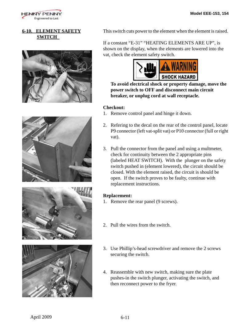
Replacement:1. Remove the rear panel (9 screws).
2. Pull the wires from the switch.
3. Use Phillip’s-head screwdriver and remove the 2 screws securing the switch.
4. Reassemble with new switch, making sure the plate pushes-in the switch plunger, activating the switch, and then reconnect power to the fryer.
6-10. ELEMENT SAFETY SWITCH
April 2009
Model EEE-153, 154
6-12
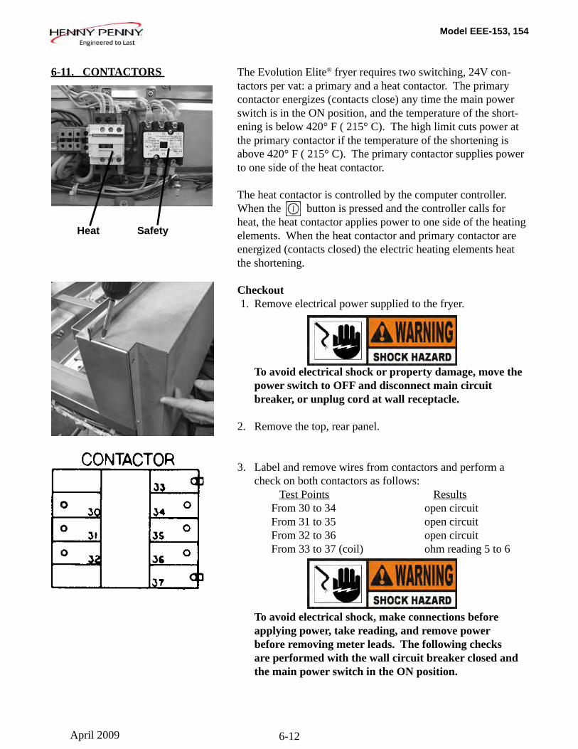
The Evolution Elite® fryer requires two switching, 24V con-tactors per vat: a primary and a heat contactor. The primary contactor energizes (contacts close) any time the main power switch is in the ON position, and the temperature of the short-ening is below 420° F ( 215° C). The high limit cuts power at the primary contactor if the temperature of the shortening is above 420° F ( 215° C). The primary contactor supplies power to one side of the heat contactor.
The heat contactor is controlled by the computer controller. When the button is pressed and the controller calls for heat, the heat contactor applies power to one side of the heating elements. When the heat contactor and primary contactor are energized (contacts closed) the electric heating elements heat the shortening.
Checkout 1. Remove electrical power supplied to the fryer.
To avoid electrical shock or property damage, move the power switch to OFF and disconnect main circuit breaker, or unplug cord at wall receptacle. 2. Remove the top, rear panel.
3. Label and remove wires from contactors and perform a check on both contactors as follows: Test Points Results From 30 to 34 open circuit From 31 to 35 open circuit
From 32 to 36 open circuitFrom 33 to 37 (coil) ohm reading 5 to 6
To avoid electrical shock, make connections before applying power, take reading, and remove power before removing meter leads. The following checks are performed with the wall circuit breaker closed and the main power switch in the ON position.
6-11. CONTACTORS
Heat Safety
April 2009
Model EEE-153, 154
6-13
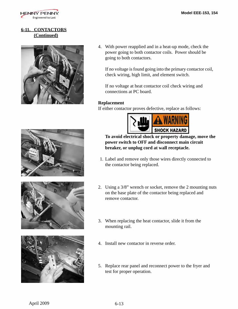
4. With power reapplied and in a heat-up mode, check the power going to both contactor coils. Power should be going to both contactors.
If no voltage is found going into the primary contactor coil, check wiring, high limit, and element switch.
If no voltage at heat contactor coil check wiring and connections at PC board.
ReplacementIf either contactor proves defective, replace as follows:
To avoid electrical shock or property damage, move the power switch to OFF and disconnect main circuit breaker, or unplug cord at wall receptacle.
1. Label and remove only those wires directly connected to the contactor being replaced.
2. Using a 3/8” wrench or socket, remove the 2 mounting nuts on the base plate of the contactor being replaced and remove contactor.
3. When replacing the heat contactor, slide it from the mounting rail.
4. Install new contactor in reverse order.
5. Replace rear panel and reconnect power to the fryer and test for proper operation.
6-11. CONTACTORS (Continued)
Heat contactor ohm check
April 2009
Model EEE-153, 154
6-14
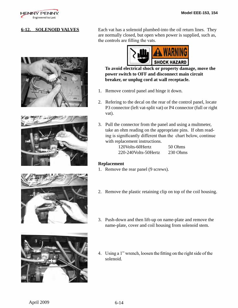
Each vat has a solenoid plumbed-into the oil return lines. They are normally closed, but open when power is supplied, such as, thecontrolsarefillingthevats.
To avoid electrical shock or property damage, move the power switch to OFF and disconnect main circuit breaker, or unplug cord at wall receptacle.
1. Remove control panel and hinge it down.
2. Refering to the decal on the rear of the control panel, locate P3 connector (left vat-split vat) or P4 connector (full or right vat).
3. Pull the connector from the panel and using a multmeter, take an ohm reading on the appropriate pins. If ohm read- ingissignificantlydifferentthanthechartbelow,continue with replacement instructions. 120Volts-60Hertz 50 Ohms 220-240Volts-50Hertz 230 Ohms
Replacement1. Remove the rear panel (9 screws).
2. Remove the plastic retaining clip on top of the coil housing.
3. Push-down and then lift-up on name-plate and remove the name-plate, cover and coil housing from solenoid stem.
4. Usinga1”wrench,loosenthefittingontherightsideofthe solenoid.
6-12. SOLENOID VALVES
April 2009
Model EEE-153, 154
6-15
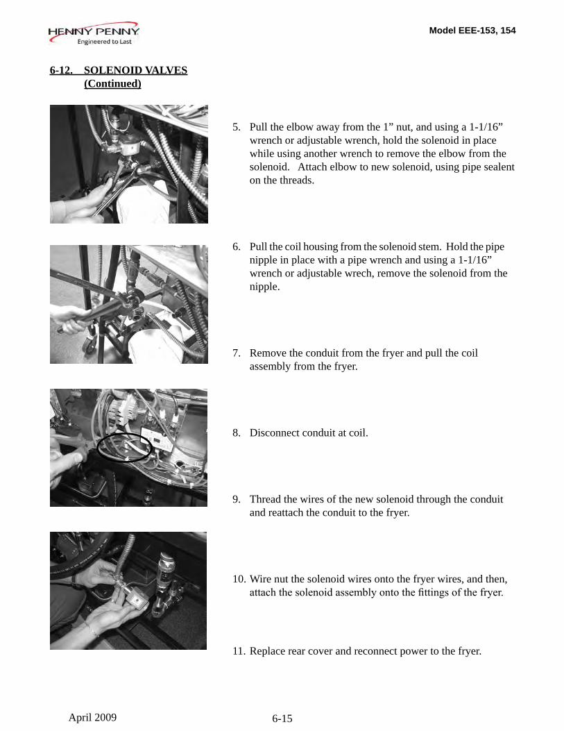
5. Pull the elbow away from the 1” nut, and using a 1-1/16” wrench or adjustable wrench, hold the solenoid in place while using another wrench to remove the elbow from the solenoid. Attach elbow to new solenoid, using pipe sealent on the threads.
6. Pull the coil housing from the solenoid stem. Hold the pipe nipple in place with a pipe wrench and using a 1-1/16” wrench or adjustable wrech, remove the solenoid from the nipple.
7. Remove the conduit from the fryer and pull the coil assembly from the fryer.
8. Disconnect conduit at coil.
9. Thread the wires of the new solenoid through the conduit and reattach the conduit to the fryer.
10. Wire nut the solenoid wires onto the fryer wires, and then, attachthesolenoidassemblyontothefittingsofthefryer.
11. Replace rear cover and reconnect power to the fryer.
6-12. SOLENOID VALVES (Continued)
April 2009
Model EEE-153, 154
6-16
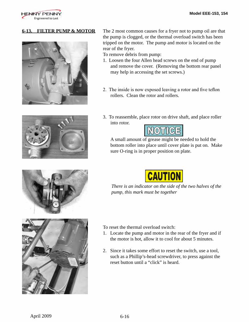
6-13. FILTER PUMP & MOTOR
The 2 most common causes for a fryer not to pump oil are that the pump is clogged, or the thermal overload switch has been tripped on the motor. The pump and motor is located on the rear of the fryer.To remove debris from pump:1. Loosen the four Allen head screws on the end of pump and remove the cover. (Removing the bottom rear panel may help in accessing the set screws.)
2.Theinsideisnowexposedleavingarotorandfiveteflon rollers. Clean the rotor and rollers.
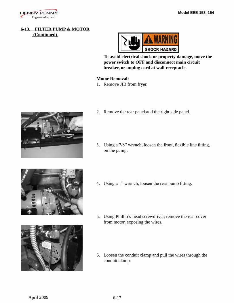
3. To reassemble, place rotor on drive shaft, and place roller into rotor.
A small amount of grease might be needed to hold the bottom roller into place until cover plate is put on. Make sure O-ring is in proper position on plate.
There is an indicator on the side of the two halves of the pump, this mark must be together
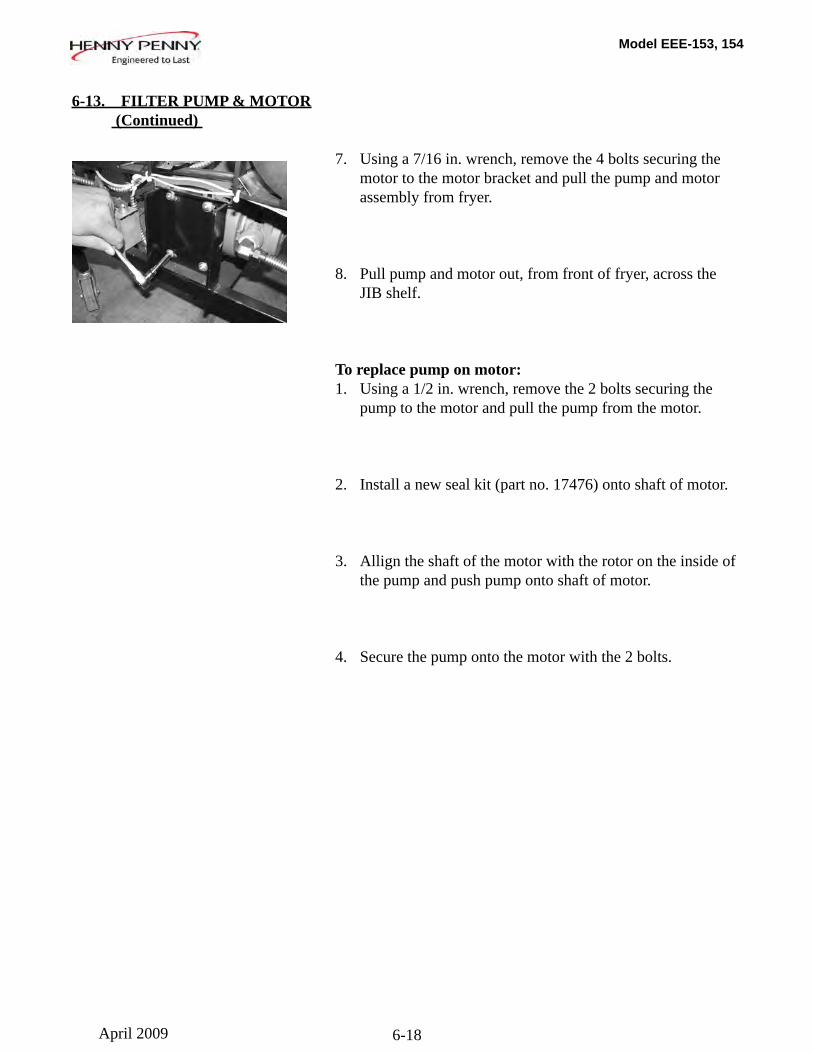
To reset the thermal overload switch:1. Locate the pump and motor in the rear of the fryer and if the motor is hot, allow it to cool for about 5 minutes.
2. Since it takes some effort to reset the switch, use a tool, such as a Phillip’s-head screwdriver, to press against the reset button until a “click” is heard.
April 2009
Model EEE-153, 154
6-17
To avoid electrical shock or property damage, move the power switch to OFF and disconnect main circuit breaker, or unplug cord at wall receptacle.
Motor Removal:1. Remove JIB from fryer.
2. Remove the rear panel and the right side panel.
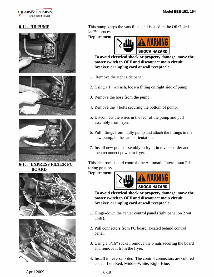
3. Usinga7/8”wrench,loosenthefront,flexiblelinefitting, on the pump.
4. Usinga1”wrench,loosentherearpumpfitting.
5. Using Phillip’s-head screwdriver, remove the rear cover from motor, exposing the wires.
6. Loosen the conduit clamp and pull the wires through the conduit clamp.
6-13. FILTER PUMP & MOTOR (Continued)
April 2009
Model EEE-153, 154
6-18
6-13. FILTER PUMP & MOTOR (Continued)
7. Using a 7/16 in. wrench, remove the 4 bolts securing the motor to the motor bracket and pull the pump and motor assembly from fryer.
8. Pull pump and motor out, from front of fryer, across the JIB shelf.
To replace pump on motor:1. Using a 1/2 in. wrench, remove the 2 bolts securing the pump to the motor and pull the pump from the motor.
2. Install a new seal kit (part no. 17476) onto shaft of motor.
3. Allign the shaft of the motor with the rotor on the inside of the pump and push pump onto shaft of motor.
4. Secure the pump onto the motor with the 2 bolts.
April 2009
Model EEE-153, 154
6-19
ThispumpkeepsthevatsfilledandisusedintheOilGuard-ian™ process.Replacement
To avoid electrical shock or property damage, move the power switch to OFF and disconnect main circuit breaker, or unplug cord at wall receptacle.
1. Remove the right side panel.
2.Usinga1”wrench,loosenfittingonrightsideofpump.
3. Remove the hose from the pump. 4. Remove the 4 bolts securing the bottom of pump.
5. Disconnect the wires in the rear of the pump and pull assembly from fryer.
6.Pullfittingsfromfaultypumpandattachthefittingstothe new pump, in the same orientation.
7. Install new pump assembly in fryer, in reverse order and then reconnect power to fryer.
This electronic board controls the Automatic Intermittant Fil-tering process.Replacement
To avoid electrical shock or property damage, move the power switch to OFF and disconnect main circuit breaker, or unplug cord at wall receptacle.
1. Hinge-down the center control panel (right panel on 2 vat units).
2. Pull connectors from PC board, located behind control panel.
3. Using a 5/16” socket, remove the 6 nuts securing the board and remove it from the fryer.
4. Install in reverse order. The control connectors are colored- coded; Left-Red; Middle-White; Right-Blue.
6-14. JIB PUMP
6-15. EXPRESS FILTER PC BOARD
April 2009
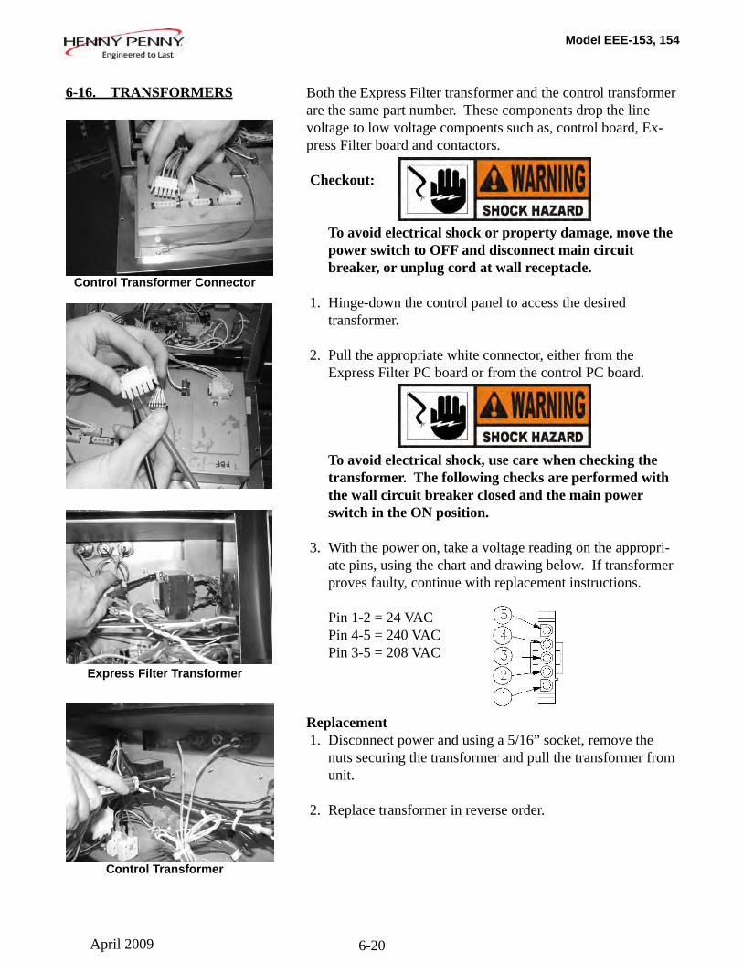
Model EEE-153, 154
6-20
Both the Express Filter transformer and the control transformer are the same part number. These components drop the line voltage to low voltage compoents such as, control board, Ex-press Filter board and contactors.
Checkout:
To avoid electrical shock or property damage, move the power switch to OFF and disconnect main circuit breaker, or unplug cord at wall receptacle. 1. Hinge-down the control panel to access the desired transformer.
2. Pull the appropriate white connector, either from the Express Filter PC board or from the control PC board.
To avoid electrical shock, use care when checking the transformer. The following checks are performed with the wall circuit breaker closed and the main power switch in the ON position.
3. With the power on, take a voltage reading on the appropri- ate pins, using the chart and drawing below. If transformer proves faulty, continue with replacement instructions.
Pin 1-2 = 24 VAC Pin 4-5 = 240 VAC Pin 3-5 = 208 VAC
Replacement 1. Disconnect power and using a 5/16” socket, remove the nuts securing the transformer and pull the transformer from unit.
2. Replace transformer in reverse order.
6-16. TRANSFORMERS
Express Filter Transformer
Control Transformer Connector
Control Transformer
April 2009
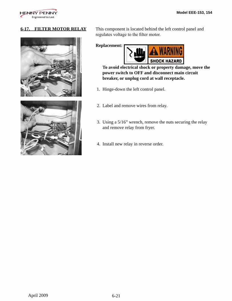
Model EEE-153, 154
6-21
This component is located behind the left control panel and regulatesvoltagetothefiltermotor.
Replacement:
To avoid electrical shock or property damage, move the power switch to OFF and disconnect main circuit breaker, or unplug cord at wall receptacle. 1. Hinge-down the left control panel.
2. Label and remove wires from relay.
3. Using a 5/16” wrench, remove the nuts securing the relay and remove relay from fryer.
4. Install new relay in reverse order.
6-17. FILTER MOTOR RELAY
April 2009
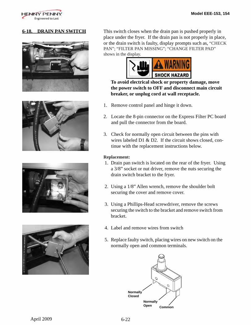
Model EEE-153, 154
6-22
6-18. DRAIN PAN SWITCH This switch closes when the drain pan is pushed properly in place under the fryer. If the drain pan is not properly in place, or the drain switch is faulty, display prompts such as, “CHECK PAN”; “FILTER PAN MISSING”; “CHANGE FILTER PAD” shows in the display.
To avoid electrical shock or property damage, move the power switch to OFF and disconnect main circuit breaker, or unplug cord at wall receptacle.
1. Remove control panel and hinge it down.
2. Locate the 8-pin connector on the Express Filter PC board and pull the connector from the board.
3. Check for normally open circuit between the pins with wires labeled D1 & D2. If the circuit shows closed, con- tinue with the replacement instructions below.
Replacement: 1. Drain pan switch is located on the rear of the fryer. Using a 3/8” socket or nut driver, remove the nuts securing the drain switch bracket to the fryer.
2. Using a 1/8” Allen wrench, remove the shoulder bolt securing the cover and remove cover.
3. Using a Phillips-Head screwdriver, remove the screws securing the switch to the bracket and remove switch from bracket.
4. Label and remove wires from switch
5. Replace faulty switch, placing wires on new switch on the normally open and common terminals.
Normally Closed
Normally Open Common
April 2009
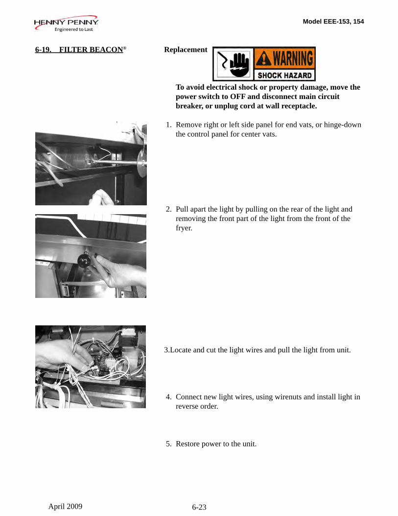
Model EEE-153, 154
6-23
6-19. FILTER BEACON® Replacement
To avoid electrical shock or property damage, move the power switch to OFF and disconnect main circuit breaker, or unplug cord at wall receptacle.
1. Remove right or left side panel for end vats, or hinge-down the control panel for center vats.
2. Pull apart the light by pulling on the rear of the light and removing the front part of the light from the front of the fryer.
3. Locate and cut the light wires and pull the light from unit.
4. Connect new light wires, using wirenuts and install light in reverse order.
5. Restore power to the unit.
April 2009
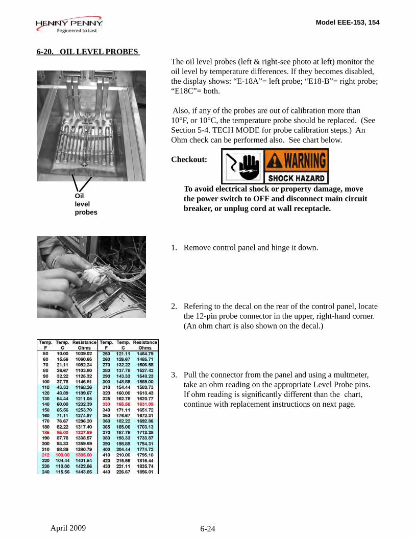
Model EEE-153, 154
6-24
The oil level probes (left & right-see photo at left) monitor the oil level by temperature differences. If they becomes disabled, the display shows: “E-18A”= left probe; “E18-B”= right probe; “E18C”= both.
Also, if any of the probes are out of calibration more than 10°F, or 10°C, the temperature probe should be replaced. (See Section 5-4. TECH MODE for probe calibration steps.) An Ohm check can be performed also. See chart below.
Checkout:
To avoid electrical shock or property damage, move the power switch to OFF and disconnect main circuit breaker, or unplug cord at wall receptacle.
1. Remove control panel and hinge it down.
2. Refering to the decal on the rear of the control panel, locate the 12-pin probe connector in the upper, right-hand corner. (An ohm chart is also shown on the decal.)
3. Pull the connector from the panel and using a multmeter, take an ohm reading on the appropriate Level Probe pins. Ifohmreadingissignificantlydifferentthanthechart, continue with replacement instructions on next page.
6-20. OIL LEVEL PROBES
Oillevelprobes
April 2009
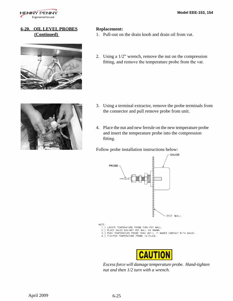
Model EEE-153, 154
6-25
Replacement:1. Pull-out on the drain knob and drain oil from vat.
2. Using a 1/2” wrench, remove the nut on the compression fitting,andremovethetemperatureprobefromthevat.
3. Using a terminal extractor, remove the probe terminals from the connector and pull remove probe from unit.
4. Place the nut and new ferrule on the new temperature probe and insert the temperature probe into the compression fitting.
Follow probe installation instructions below:
Excess force will damage temperature probe. Hand-tighten nut and then 1/2 turn with a wrench.
6-20. OIL LEVEL PROBES (Continued)
April 2009
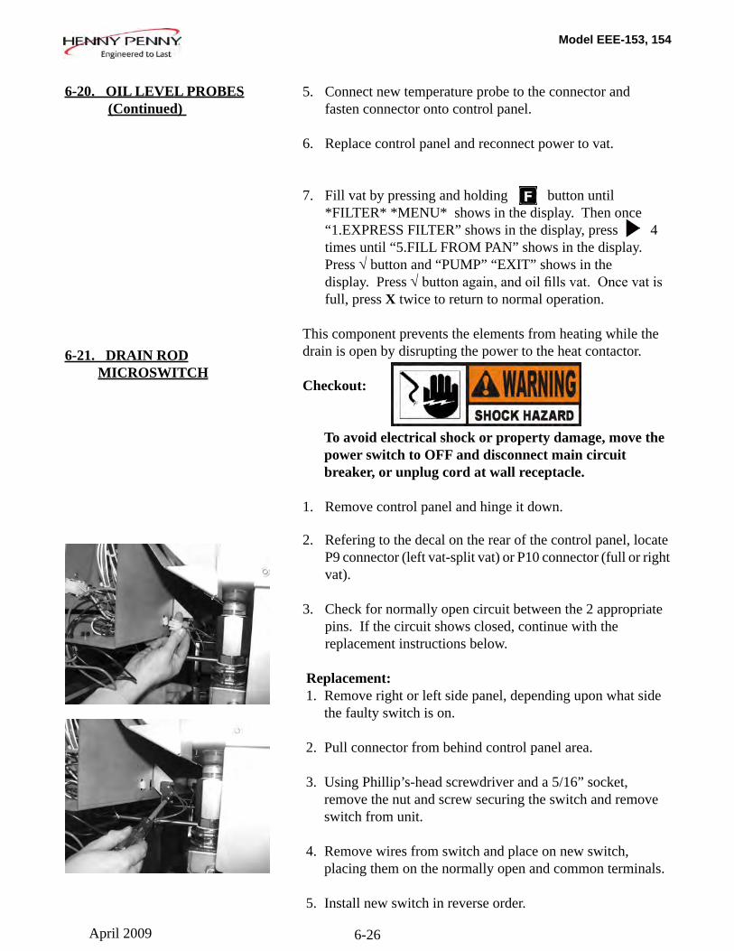
Model EEE-153, 154
6-26
5. Connect new temperature probe to the connector and fasten connector onto control panel.
6. Replace control panel and reconnect power to vat.
7. Fill vat by pressing and holding button until *FILTER* *MENU* shows in the display. Then once “1.EXPRESS FILTER” shows in the display, press 4 times until “5.FILL FROM PAN” shows in the display. Press √ button and “PUMP” “EXIT” shows in the display. Press √buttonagain,andoilfillsvat.Oncevatis full, press X twice to return to normal operation.
This component prevents the elements from heating while the drain is open by disrupting the power to the heat contactor.
Checkout:
To avoid electrical shock or property damage, move the power switch to OFF and disconnect main circuit breaker, or unplug cord at wall receptacle.
1. Remove control panel and hinge it down.
2. Refering to the decal on the rear of the control panel, locate P9 connector (left vat-split vat) or P10 connector (full or right vat).
3. Check for normally open circuit between the 2 appropriate pins. If the circuit shows closed, continue with the replacement instructions below.
Replacement: 1. Remove right or left side panel, depending upon what side the faulty switch is on.
2. Pull connector from behind control panel area.
3. Using Phillip’s-head screwdriver and a 5/16” socket, remove the nut and screw securing the switch and remove switch from unit.
4. Remove wires from switch and place on new switch, placing them on the normally open and common terminals. 5. Install new switch in reverse order.
6-20. OIL LEVEL PROBES (Continued)
6-21. DRAIN ROD MICROSWITCH
April 2009
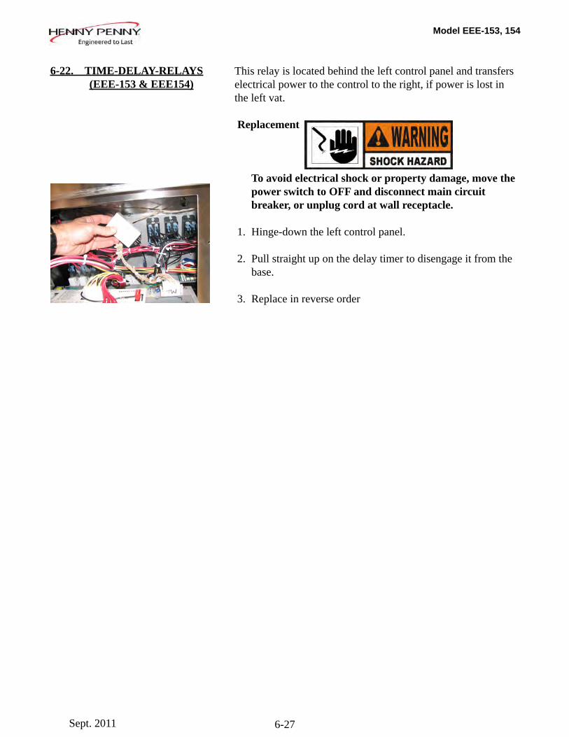
Model EEE-153, 154
6-27
This relay is located behind the left control panel and transfers electrical power to the control to the right, if power is lost in the left vat.
Replacement
To avoid electrical shock or property damage, move the power switch to OFF and disconnect main circuit breaker, or unplug cord at wall receptacle. 1. Hinge-down the left control panel.
2. Pull straight up on the delay timer to disengage it from the base.
3. Replace in reverse order
6-22. TIME-DELAY-RELAYS (EEE-153 & EEE154)
Sept. 2011
Model EEE-153, 154
6-28
208/240 VOLTWIRING
DIAGRAMS
The legend below helps in identifying the components of the wiring diagrams on the following wiring diagrams.
Sept. 2011
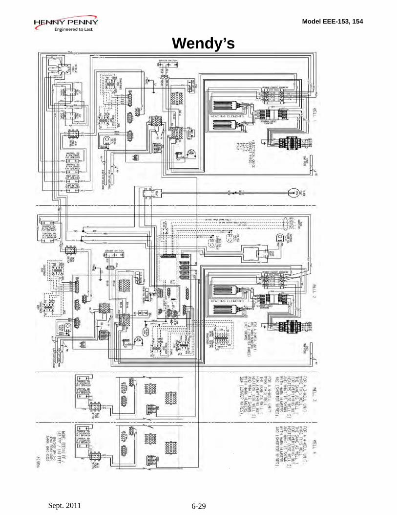
Model EEE-153, 154
6-29
Wendy’s
Sept. 2011

Model EEE-153, 154
7-1
SECTION 7. PARTS INFORMATION
7-1. INTRODUCTION This section lists the replaceable parts of the Henny Penny Evolution Elite® fryer.
7-2. GENUINE PARTS Use only genuine Henny Penny parts in your fryer. Using a part of lesser quality or substitute design may result in damage to the unit or personal injury.
7-3. WHEN ORDERING PARTS Once the parts that you want to order have been found in the parts list, write down the following information:
Item Number 2 Part Number 60241 Example: Description High Limit
From the data plate, list the following information:
Product Number 01100 Serial Number 0001 Example: Voltage 208
7-4. PRICES Your distributor has a price parts list and will be glad to inform you of the cost of your parts order.
7-5. DELIVERY Commonly replaced items are stocked by your distributor and will be sent out when your order is received. Other parts will be ordered, by your distributor, from Henny Penny Corpora- tion. Normally, these will be sent to your distributor within three working days.
7-6. WARRANTY All replacement parts (except lamps and fuses) are warranted for 90 days against manufacturing defects and workmanship. If damage occurs during shipping, notify the carrier at once so thataclaimmaybeproperlyfiled.Refertowarrantyinthe front of this manual for other rights and limitations.
Recommended replacement parts are indicated with A or B in the parts lists: A = parts to be stocked on service vans or trucks B = parts to be stocked at the distributor/KES location. Inventory on all other parts not identif ed, should be based upon usage in the territory. Please use care when ordering recommended parts, because all voltages and variations a marked. Distributors should order parts based upon comm voltages and equipment sold in their territory.
7-7. RECOMMENDED SPARE PARTS FORDISTRIBUTORS
Sept. 2011
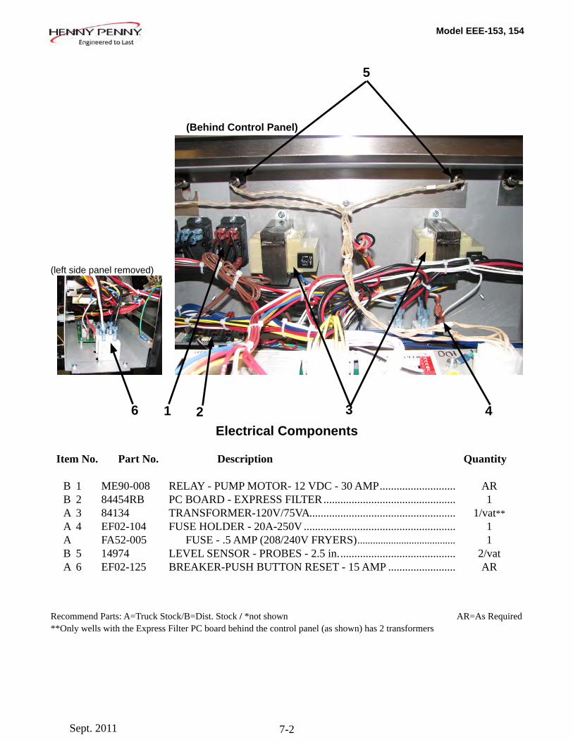
Model EEE-153, 154
7-2
(Behind Control Panel)
Item No. Part No. Description Quantity B 1 ME90-008 RELAY - PUMP MOTOR- 12 VDC - 30 AMP ........................... AR B 2 84454RB PC BOARD - EXPRESS FILTER ............................................... 1 A 3 84134 TRANSFORMER-120V/75VA .................................................... 1/vat** A 4 EF02-104 FUSE HOLDER - 20A-250V ...................................................... 1 A FA52-005 FUSE - .5 AMP (208/240V FRYERS) ...................................... 1 B 5 14974 LEVEL SENSOR - PROBES - 2.5 in. ......................................... 2/vat A 6 EF02-125 BREAKER-PUSH BUTTON RESET - 15 AMP ........................ AR
Recommend Parts: A=Truck Stock/B=Dist. Stock / *not shown AR=As Required**Only wells with the Express Filter PC board behind the control panel (as shown) has 2 transformers
(left side panel removed)
Electrical Components1 2 3 4
5
6
Sept. 2011
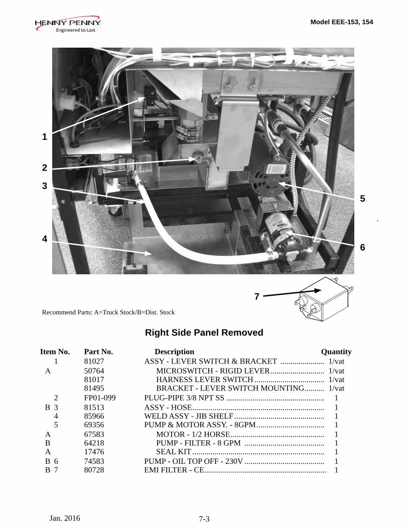
Model EEE-153, 154
7-3
Item No. Part No. Description Quantity 1 81027 ASSY - LEVER SWITCH & BRACKET ...................... 1/vat Α 50764 MICROSWITCH - RIGID LEVER ........................... 1/vat 81017 HARNESS LEVER SWITCH ................................... 1/vat 81495 BRACKET - LEVER SWITCH MOUNTING .......... 1/vat 2 FP01-099 PLUG-PIPE 3/8 NPT SS ................................................. 1 Β 3 81513 ASSY - HOSE .................................................................. 1 4 85966 WELD ASSY - JIB SHELF ............................................. 1 5 69356 PUMP & MOTOR ASSY. - 8GPM .................................. 1 Α 67583 MOTOR - 1/2 HORSE ............................................... 1 B 64218 PUMP - FILTER - 8 GPM ........................................ 1 A 17476 SEAL KIT .................................................................. 1 B 6 74583 PUMP - OIL TOP OFF - 230V ........................................ 1 B 7 80728 EMI FILTER - CE............................................................. 1
4
5
Recommend Parts: A=Truck Stock/B=Dist. Stock
1
2
3
6
Right Side Panel Removed
7
Jan. 2016
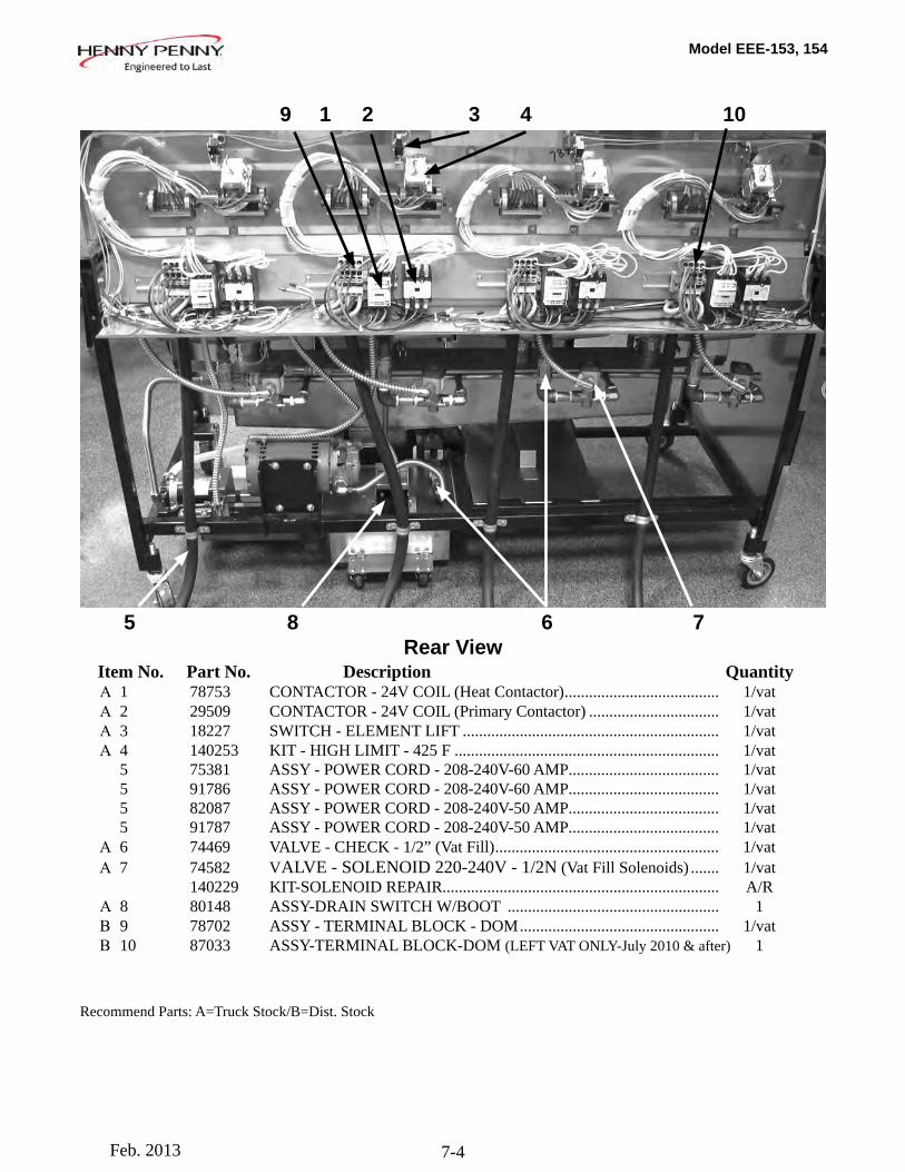
Model EEE-153, 154
7-4
Rear View Item No. Part No. Description Quantity Α 1 78753 CONTACTOR - 24V COIL (Heat Contactor) ...................................... 1/vat Α 2 29509 CONTACTOR - 24V COIL (Primary Contactor) ................................ 1/vat Α 3 18227 SWITCH - ELEMENT LIFT ............................................................... 1/vat Α 4 140253 KIT - HIGH LIMIT - 425 F ................................................................. 1/vat 5 75381 ASSY - POWER CORD - 208-240V-60 AMP ..................................... 1/vat 5 91786 ASSY - POWER CORD - 208-240V-60 AMP ..................................... 1/vat 5 82087 ASSY - POWER CORD - 208-240V-50 AMP ..................................... 1/vat 5 91787 ASSY - POWER CORD - 208-240V-50 AMP ..................................... 1/vat Α 6 74469 VALVE - CHECK - 1/2” (Vat Fill) ....................................................... 1/vat Α 7 74582 VALVE - SOLENOID 220-240V - 1/2N (Vat Fill Solenoids) ....... 1/vat 140229 KIT-SOLENOID REPAIR.................................................................... A/R Α 8 80148 ASSY-DRAIN SWITCH W/BOOT .................................................... 1 Β 9 78702 ASSY - TERMINAL BLOCK - DOM ................................................. 1/vat Β 10 87033 ASSY-TERMINAL BLOCK-DOM (LEFT VAT ONLY-July 2010 & after) 1
Recommend Parts: A=Truck Stock/B=Dist. Stock
1 2 3 4
5 6 78
9 10
Feb. 2013
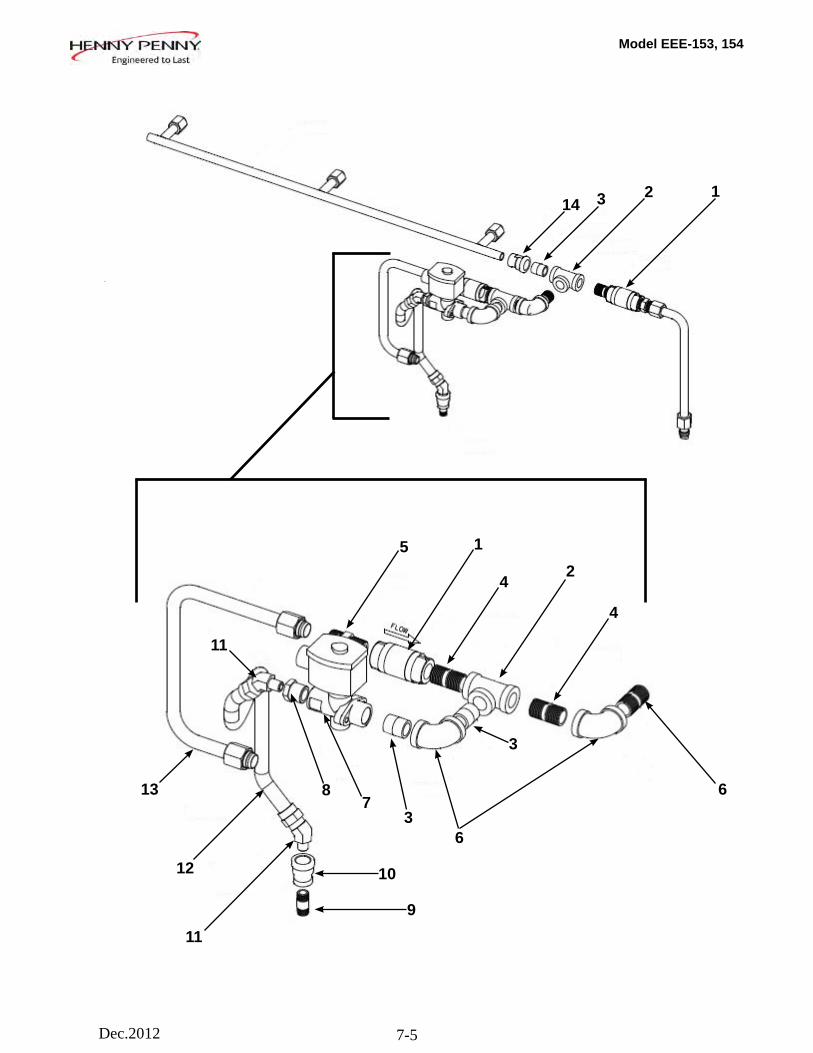
Model EEE-153, 154
7-5
12
2
3
6
3
3
4
4
15
6
78
9
10
11
11
12
13
14
Dec.2012
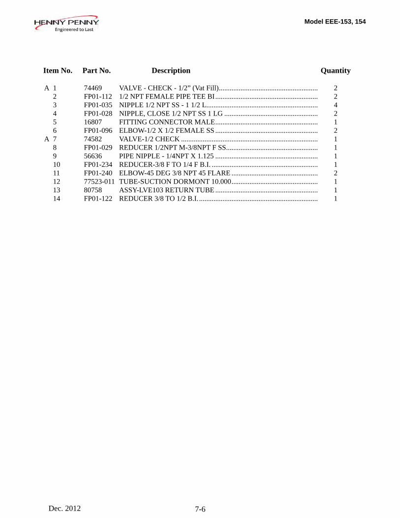
Model EEE-153, 154
7-6Dec. 2012
Item No. Part No. Description Quantity A 1 74469 VALVE - CHECK - 1/2” (Vat Fill) ....................................................... 2 2 FP01-112 1/2 NPT FEMALE PIPE TEE BI ......................................................... 2 3 FP01-035 NIPPLE 1/2 NPT SS - 1 1/2 L .............................................................. 4 4 FP01-028 NIPPLE, CLOSE 1/2 NPT SS 1 LG .................................................... 2 5 16807 FITTING CONNECTOR MALE ......................................................... 1 6 FP01-096 ELBOW-1/2 X 1/2 FEMALE SS ......................................................... 2 A 7 74582 VALVE-1/2 CHECK ............................................................................ 1 8 FP01-029 REDUCER 1/2NPT M-3/8NPT F SS ................................................... 1 9 56636 PIPE NIPPLE - 1/4NPT X 1.125 ......................................................... 1 10 FP01-234 REDUCER-3/8 F TO 1/4 F B.I. ........................................................... 1 11 FP01-240 ELBOW-45 DEG 3/8 NPT 45 FLARE ................................................ 2 12 77523-011 TUBE-SUCTION DORMONT 10.000 ................................................ 1 13 80758 ASSY-LVE103 RETURN TUBE ......................................................... 1 14 FP01-122 REDUCER 3/8 TO 1/2 B.I. .................................................................. 1
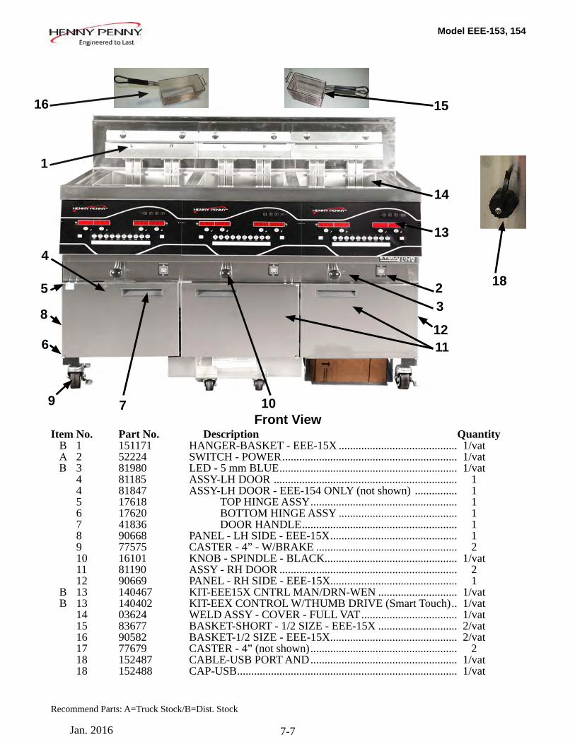
Model EEE-153, 154
7-7
Recommend Parts: A=Truck Stock/B=Dist. Stock
Item No. Part No. Description Quantity B 1 151171 HANGER-BASKET - EEE-15X .......................................... 1/vat Α 2 52224 SWITCH - POWER .............................................................. 1/vat Β 3 81980 LED - 5 mm BLUE ............................................................... 1/vat 4 81185 ASSY-LH DOOR ................................................................. 1 4 81847 ASSY-LH DOOR - EEE-154 ONLY (not shown) ............... 1 5 17618 TOP HINGE ASSY .................................................... 1 6 17620 BOTTOM HINGE ASSY .......................................... 1 7 41836 DOOR HANDLE ....................................................... 1 8 90668 PANEL - LH SIDE - EEE-15X ............................................. 1 9 77575 CASTER - 4” - W/BRAKE .................................................. 2 10 16101 KNOB - SPINDLE - BLACK............................................... 1/vat 11 81190 ASSY - RH DOOR ............................................................... 2 12 90669 PANEL - RH SIDE - EEE-15X............................................. 1 B 13 140467 KIT-EEE15X CNTRL MAN/DRN-WEN ............................ 1/vat B 13 140402 KIT-EEX CONTROL W/THUMB DRIVE (Smart Touch) .. 1/vat 14 03624 WELD ASSY - COVER - FULL VAT .................................. 1/vat 15 83677 BASKET-SHORT - 1/2 SIZE - EEE-15X ............................ 2/vat 16 90582 BASKET-1/2 SIZE - EEE-15X ............................................. 2/vat 17 77679 CASTER - 4” (not shown) .................................................... 2 18 152487 CABLE-USB PORT AND .................................................... 1/vat 18 152488 CAP-USB .............................................................................. 1/vat
1
23
4
13
6
8
5
9 7
11
18
12
10Front View
14
1516
Jan. 2016
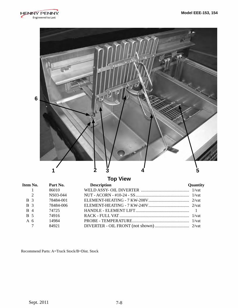
Model EEE-153, 154
7-8
1 2 3 4 5
Item No. Part No. Description Quantity 1 86010 WELD ASSY- OIL DIVERTER ............................................. 1/vat 2 NS03-044 NUT - ACORN - #10-24 - SS .................................................. 1/vat Β 3 78484-001 ELEMENT-HEATING - 7 KW-208V ...................................... 2/vat Β 3 78484-006 ELEMENT-HEATING - 7 KW-240V ...................................... 2/vat Β 4 74725 HANDLE - ELEMENT LIFT .................................................. 1 Β 5 74916 RACK - FULL VAT ................................................................. 1/vat Α 6 14984 PROBE - TEMPERATURE ..................................................... 1/vat 7 84921 DIVERTER - OIL FRONT (not shown) ................................ 2/vat
6
Recommend Parts: A=Truck Stock/B=Dist. Stock
Top View
Sept. 2011
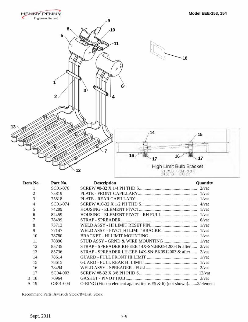
Model EEE-153, 154
7-9
Item No. Part No. Description Quantity 1 SC01-076 SCREW #8-32 X 1/4 PH THD S .................................................... 2/vat 2 75819 PLATE - FRONT CAPILLARY ..................................................... 1/vat 3 75818 PLATE - REAR CAPILLARY ....................................................... 1/vat 4 SC01-074 SCREW #10-32 X 1/2 PH THD S .................................................. 4/vat 5 74209 HOUSING - ELEMENT PIVOT .................................................... 1/vat 6 82459 HOUSING - ELEMENT PIVOT - RH FULL ................................ 1/vat 7 78499 STRAP - SPREADER .................................................................... 6/vat 8 73713 WELD ASSY - HI LIMIT RESET PIN .......................................... 1/vat 9 77147 WELD ASSY - PIVOT HI LIMIT BRACKET .............................. 1/vat 10 78780 BRACKET - HI LIMIT MOUNTING ........................................... 1/vat 11 78896 STUD ASSY - GRND & WIRE MOUNTING .............................. 1/vat 12 85735 STRAP - SPREADER RH-EEE 14X-SN:BK0912003 & after ..... 2/vat 13 85736 STRAP - SPREADER LH-EEE 14X-SN:BK0912003 & after ...... 2/vat 14 78614 GUARD - FULL FRONT HI LIMIT ............................................. 1/vat 15 78615 GUARD - FULL REAR HI LIMIT ................................................ 1/vat 16 78494 WELD ASSY - SPREADER - FULL ............................................. 2/vat 17 SC04-003 SCREW #8-32 X 3/8 PH PHD S .................................................... 12/vat B 18 76964 GASKET - PIVOT HUB ................................................................ 2/vat A 19 OR01-004 O-RING (Fits on element against items #5 & 6) (not shown)........ 2/element
Recommend Parts: A=Truck Stock/B=Dist. Stock
18
1
2
5
4
63
8
9
10
11
7
12
13
1716
14 15
16 17
Sept. 2011
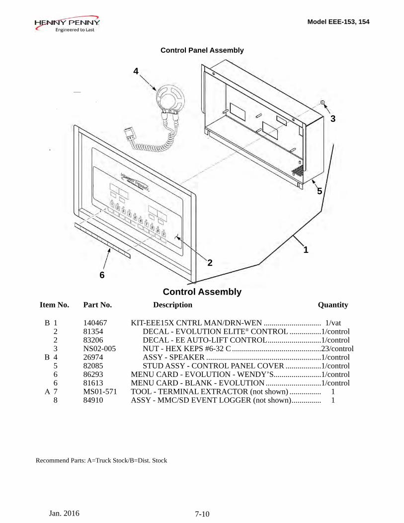
Model EEE-153, 154
7-10
Item No. Part No. Description Quantity
B 1 140467 KIT-EEE15X CNTRL MAN/DRN-WEN ............................. 1/vat 2 81354 DECAL - EVOLUTION ELITE® CONTROL ................ 1/control 2 83206 DECAL - EE AUTO-LIFT CONTROL ........................... 1/control 3 NS02-005 NUT - HEX KEPS #6-32 C ............................................. 23/control Β 4 26974 ASSY - SPEAKER .......................................................... 1/control 5 82085 STUD ASSY - CONTROL PANEL COVER .................. 1/control 6 86293 MENU CARD - EVOLUTION - WENDY’S........................ 1/control 6 81613 MENU CARD - BLANK - EVOLUTION ............................ 1/control Α 7 MS01-571 TOOL - TERMINAL EXTRACTOR (not shown) ................ 1 8 84910 ASSY - MMC/SD EVENT LOGGER (not shown) ............... 1
12
3
4
5
6
Control Panel Assembly
Recommend Parts: A=Truck Stock/B=Dist. Stock
Control Assembly
Jan. 2016
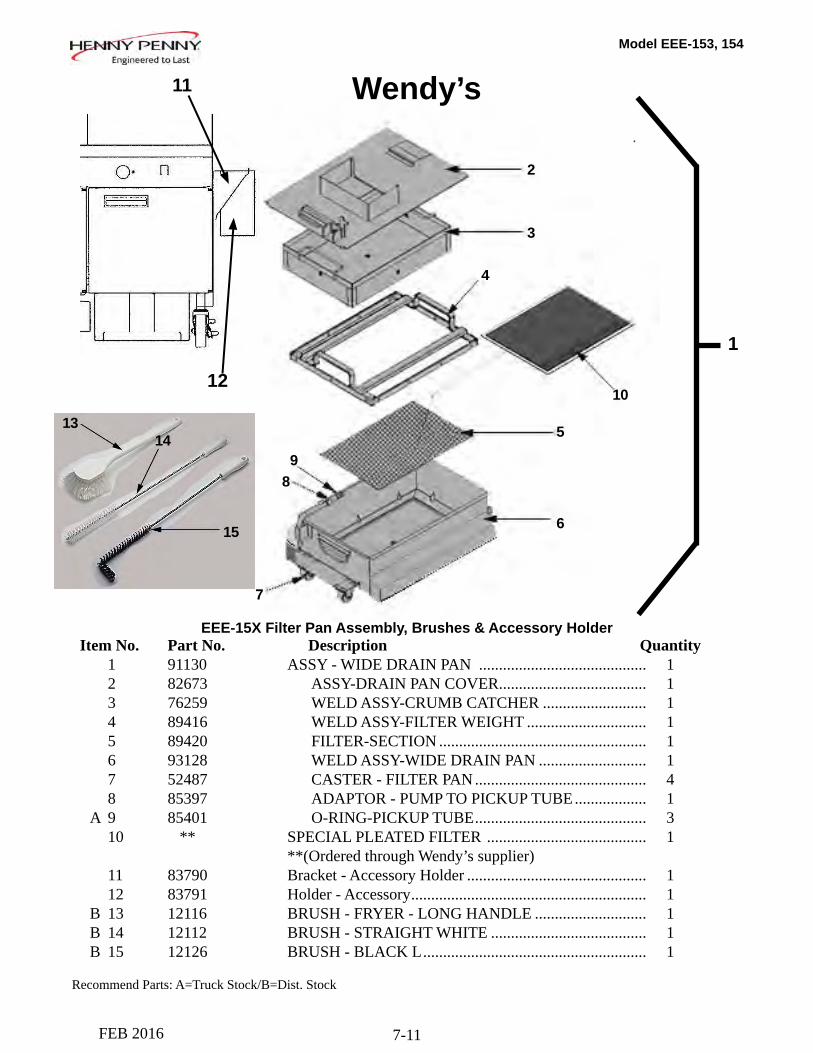
Model EEE-153, 154
7-11
1
2
3
4
5
6
7
8
10
9
Item No. Part No. Description Quantity 1 91130 ASSY - WIDE DRAIN PAN .......................................... 1 2 82673 ASSY-DRAIN PAN COVER ..................................... 1 3 76259 WELD ASSY-CRUMB CATCHER .......................... 1 4 89416 WELD ASSY-FILTER WEIGHT .............................. 1 5 89420 FILTER-SECTION .................................................... 1 6 93128 WELD ASSY-WIDE DRAIN PAN ........................... 1 7 52487 CASTER - FILTER PAN ........................................... 4 8 85397 ADAPTOR - PUMP TO PICKUP TUBE .................. 1 A 9 85401 O-RING-PICKUP TUBE ........................................... 3 10 ** SPECIAL PLEATED FILTER ........................................ 1 **(Ordered through Wendy’s supplier) 11 83790 Bracket - Accessory Holder ............................................. 1 12 83791 Holder - Accessory ........................................................... 1 B 13 12116 BRUSH - FRYER - LONG HANDLE ............................ 1 B 14 12112 BRUSH - STRAIGHT WHITE ....................................... 1 B 15 12126 BRUSH - BLACK L ........................................................ 1
EEE-15X Filter Pan Assembly, Brushes & Accessory Holder
Recommend Parts: A=Truck Stock/B=Dist. Stock
12
11
15
1413
Wendy’s
FEB 2016
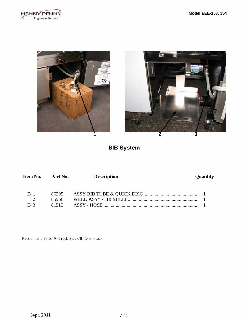
Model EEE-153, 154
7-12
Item No. Part No. Description Quantity
B 1 86295 ASSY-BIB TUBE & QUICK DISC ........................................... 1 2 85966 WELD ASSY - JIB SHELF ......................................................... 1 B 3 81513 ASSY - HOSE ............................................................................. 1
1 32
Recommend Parts: A=Truck Stock/B=Dist. Stock
BIB System
Sept. 2011
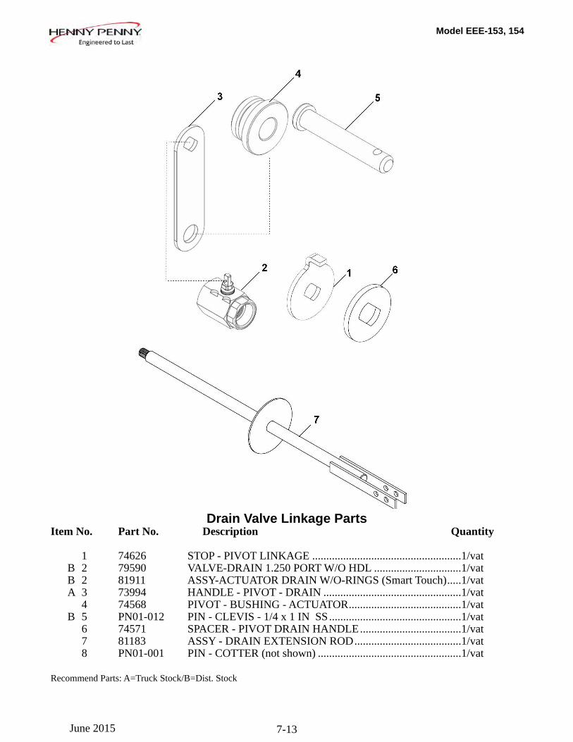
Model EEE-153, 154
7-13
Drain Valve Linkage Parts Item No. Part No. Description Quantity
1 74626 STOP - PIVOT LINKAGE .....................................................1/vat B 2 79590 VALVE-DRAIN 1.250 PORT W/O HDL ...............................1/vat B 2 81911 ASSY-ACTUATOR DRAIN W/O-RINGS (Smart Touch) .....1/vat A 3 73994 HANDLE - PIVOT - DRAIN .................................................1/vat 4 74568 PIVOT - BUSHING - ACTUATOR ........................................1/vat B 5 PN01-012 PIN - CLEVIS - 1/4 x 1 IN SS ...............................................1/vat 6 74571 SPACER - PIVOT DRAIN HANDLE ....................................1/vat 7 81183 ASSY - DRAIN EXTENSION ROD ......................................1/vat 8 PN01-001 PIN - COTTER (not shown) ...................................................1/vat
Recommend Parts: A=Truck Stock/B=Dist. Stock
June 2015
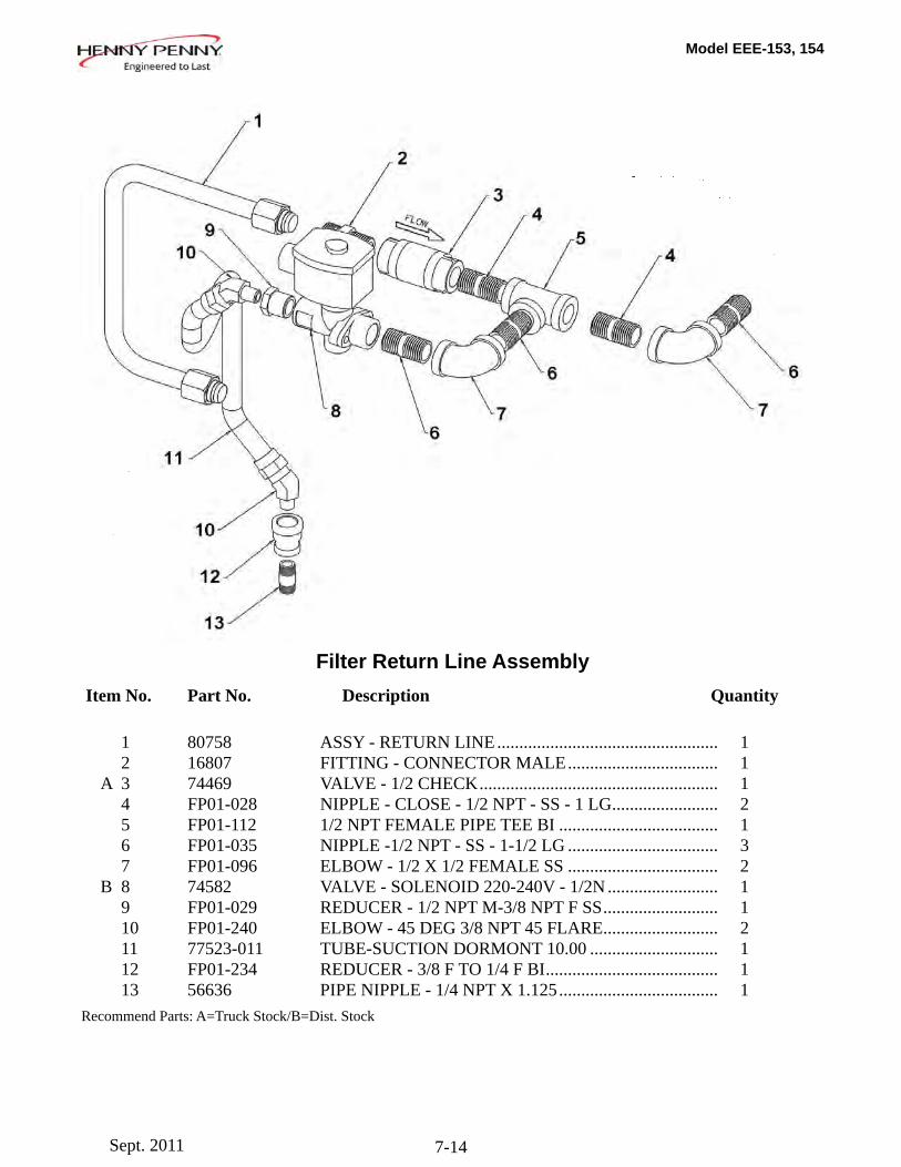
Model EEE-153, 154
7-14
Item No. Part No. Description Quantity
1 80758 ASSY - RETURN LINE .................................................. 1 2 16807 FITTING - CONNECTOR MALE .................................. 1 A 3 74469 VALVE - 1/2 CHECK ...................................................... 1 4 FP01-028 NIPPLE - CLOSE - 1/2 NPT - SS - 1 LG ........................ 2 5 FP01-112 1/2 NPT FEMALE PIPE TEE BI .................................... 1 6 FP01-035 NIPPLE -1/2 NPT - SS - 1-1/2 LG .................................. 3 7 FP01-096 ELBOW - 1/2 X 1/2 FEMALE SS .................................. 2 B 8 74582 VALVE - SOLENOID 220-240V - 1/2N ......................... 1 9 FP01-029 REDUCER - 1/2 NPT M-3/8 NPT F SS .......................... 1 10 FP01-240 ELBOW - 45 DEG 3/8 NPT 45 FLARE .......................... 2 11 77523-011 TUBE-SUCTION DORMONT 10.00 ............................. 1 12 FP01-234 REDUCER - 3/8 F TO 1/4 F BI ....................................... 1 13 56636 PIPE NIPPLE - 1/4 NPT X 1.125 .................................... 1Recommend Parts: A=Truck Stock/B=Dist. Stock
Filter Return Line Assembly
Sept. 2011
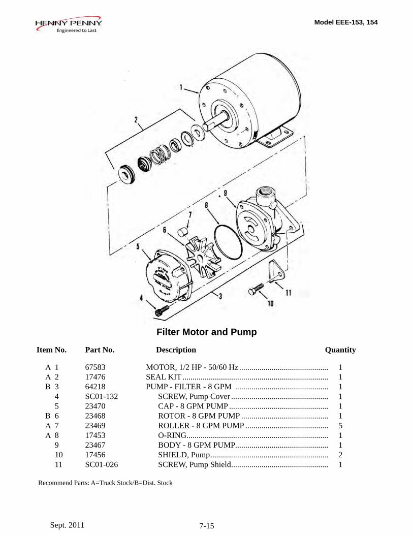
Model EEE-153, 154
7-15
Filter Motor and Pump
Item No. Part No. Description Quantity
Α 1 67583 MOTOR, 1/2 HP - 50/60 Hz ............................................ 1 Α 2 17476 SEAL KIT ........................................................................ 1 Β 3 64218 PUMP - FILTER - 8 GPM .............................................. 1 4 SC01-132 SCREW, Pump Cover ................................................ 1 5 23470 CAP - 8 GPM PUMP ................................................. 1 Β 6 23468 ROTOR - 8 GPM PUMP ........................................... 1 Α 7 23469 ROLLER - 8 GPM PUMP ......................................... 5 Α 8 17453 O-RING ...................................................................... 1 9 23467 BODY - 8 GPM PUMP .............................................. 1 10 17456 SHIELD, Pump .......................................................... 2 11 SC01-026 SCREW, Pump Shield ................................................ 1
Recommend Parts: A=Truck Stock/B=Dist. Stock
Sept. 2011
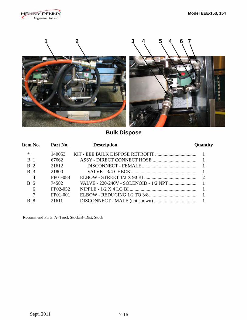
Model EEE-153, 154
7-16
Bulk Dispose
Item No. Part No. Description Quantity
* 140053 KIT - EEE BULK DISPOSE RETROFIT .................................. 1 Β 1 67662 ASSY - DIRECT CONNECT HOSE .................................... 1 Β 2 21612 DISCONNECT - FEMALE ............................................. 1 Β 3 21800 VALVE - 3/4 CHECK ...................................................... 1 4 FP01-088 ELBOW - STREET 1/2 X 90 BI ........................................... 2 Β 5 74582 VALVE - 220-240V - SOLENOID - 1/2 NPT ....................... 1 6 FP02-052 NIPPLE - 1/2 X 4 LG BI ....................................................... 1 7 FP01-001 ELBOW - REDUCING 1/2 TO 3/8 ....................................... 1 Β 8 21611 DISCONNECT - MALE (not shown) ................................... 1 Recommend Parts: A=Truck Stock/B=Dist. Stock
1 2 3 4 5 6 74
Sept. 2011
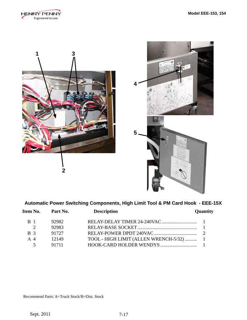
Model EEE-153, 154
7-17
Automatic Power Switching Components, High Limit Tool & PM Card Hook - EEE-15X Item No. Part No. Description Quantity
Β 1 92982 RELAY-DELAY TIMER 24-240VAC ............................. 1 2 92983 RELAY-BASE SOCKET ................................................. 1 Β 3 91727 RELAY-POWER DPDT 240VAC ................................... 2 Α 4 12149 TOOL - HIGH LIMIT (ALLEN WRENCH-5/32) .......... 1 5 91711 HOOK-CARD HOLDER WENDYS .............................. 1
Recommend Parts: A=Truck Stock/B=Dist. Stock
1 3
4
5
2
Sept. 2011

