technical manual line coupler scn lk - mdt · pdf filetechnical manual line coupler scn‐lk...
TRANSCRIPT

Technical Manual Line Coupler SCN‐LK
MDT technologies GmbH • 51766 Engelskirchen • Papiermühle 1 Tel.: +49-2263-880 • Fax: +49-2263-4588 • [email protected] • www.mdt.de
2
1 Content 1 Content ................................................................................................................................................. 2
2 Overview ............................................................................................................................................... 3
2.1 Usage ............................................................................................................................................. 3
2.1.1 Coupler ................................................................................................................................... 3
2.1.2 Repeater ................................................................................................................................. 3
2.2 Exemplary circuit diagram ............................................................................................................. 4
2.3 Structure & Handling ..................................................................................................................... 5
2.3.1 LED‐Display ............................................................................................................................. 6
2.3.2 Function button ...................................................................................................................... 7
3 ETS‐Parameters .................................................................................................................................... 8
3.1 Coupler .......................................................................................................................................... 8
3.1.1 Functions ................................................................................................................................ 8
3.1.2 General ................................................................................................................................... 9
3.1.3 Main Line .............................................................................................................................. 10
3.1.4 Sub Line ................................................................................................................................ 12
3.2 Repeater ...................................................................................................................................... 14
3.2.1 Functions .............................................................................................................................. 14
3.2.2 General ................................................................................................................................. 15
3.2.3 Main Line .............................................................................................................................. 15
3.2.4 Sub line ................................................................................................................................. 17
4 Settings at the ETS .............................................................................................................................. 18
4.1 Topology of the project ............................................................................................................... 18
4.2 Telegram Forwarding .................................................................................................................. 20
4.3 Generating Filter Table ................................................................................................................ 20
4.4 Preview Filter Table ..................................................................................................................... 21
4.5 Approach at startup .................................................................................................................... 22
5 Index ................................................................................................................................................... 23
5.1 Register of illustrations ................................................................................................................ 23
5.2 List of tables................................................................................................................................. 23
6 Attachment ......................................................................................................................................... 24
6.1 Statutory requirements ............................................................................................................... 24
6.2 Routine disposal .......................................................................................................................... 24
6.3 Assemblage .................................................................................................................................. 24
6.4 Datasheet .................................................................................................................................... 25

Technical Manual Line Coupler SCN‐LK
MDT technologies GmbH • 51766 Engelskirchen • Papiermühle 1 Tel.: +49-2263-880 • Fax: +49-2263-4588 • [email protected] • www.mdt.de
3
2Overview
2.1Usage The SCN‐LK can be used as well as Coupler or as Repeater.
2.1.1Coupler The basic functionality of SCN‐LK is coupling a KNX‐TP‐mainline with a KNX‐TP‐sub line. SCN‐LK provides galvanic isolation between the two connected lines. Due to the flexibility of SCN‐LK, the coupler can be used as a line coupler to connect a line to a main line or as a backbone coupler to connect a main line to a backbone line. The main task of SCN‐LK is filtering the traffic according the installation place in the hierarchy or according to the built in filter tables for group oriented communication. The SCN‐LK provides outstanding features compared to other similar products, for example support for long messages (up to 250 byte length) and a configurable one button activation of special functions. These are helpful during installation, during run time and for trouble shooting. The high informative 6 duo LED display shows accurate the bus status on each line. This helps identifying common communication problems due to bus load or retransmissions on both lines.
2.1.2Repeater The function SCN‐LK of as repeater has the target to link two lines for data transfer. SCN‐LK as repeater still provides galvanic isolation between the connected lines. Up to three line repeaters can be used behind a line coupler. As a result, up to four lines can form a complete line. Each line must be supplied by a dedicated KNX power supply.
Technical Manual Line Coupler SCN‐LK
MDT technologies GmbH • 51766 Engelskirchen • Papiermühle 1 Tel.: +49-2263-880 • Fax: +49-2263-4588 • [email protected] • www.mdt.de
4
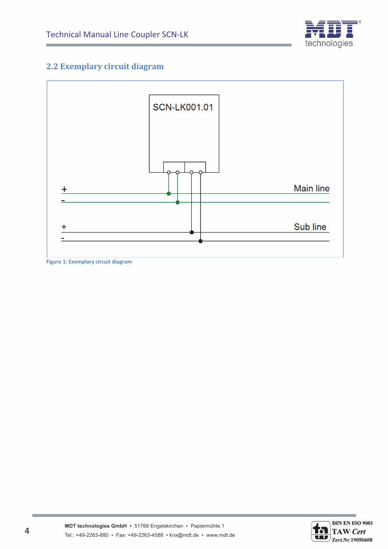
2.2Exemplarycircuitdiagram
Figure 1: Exemplary circuit diagram
Technical Manual Line Coupler SCN‐LK
MDT technologies GmbH • 51766 Engelskirchen • Papiermühle 1 Tel.: +49-2263-880 • Fax: +49-2263-4588 • [email protected] • www.mdt.de
5
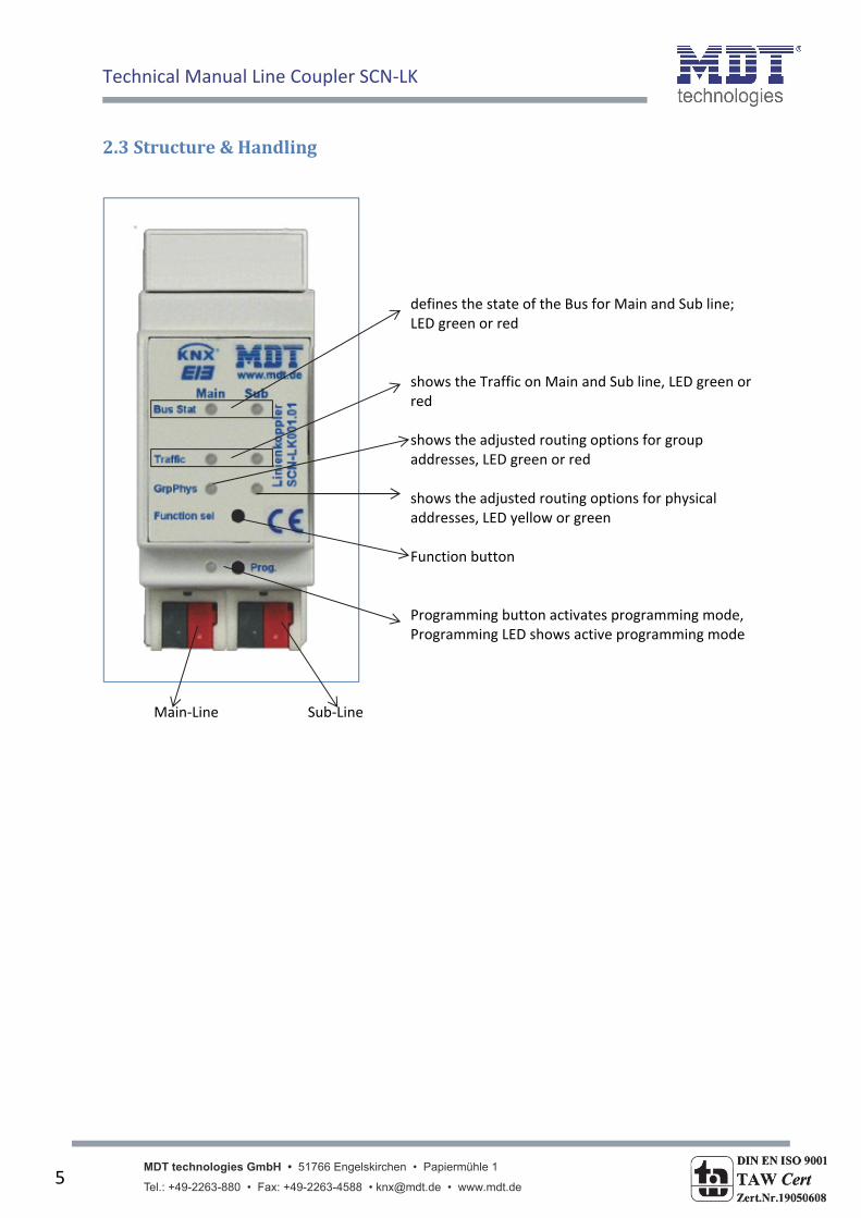
2.3Structure&Handling
defines the state of the Bus for Main and Sub line; LED green or red shows the Traffic on Main and Sub line, LED green or red shows the adjusted routing options for group addresses, LED green or red shows the adjusted routing options for physical addresses, LED yellow or green Function button Programming button activates programming mode, Programming LED shows active programming mode
Main‐Line Sub‐Line
Technical Manual Line Coupler SCN‐LK
MDT technologies GmbH • 51766 Engelskirchen • Papiermühle 1 Tel.: +49-2263-880 • Fax: +49-2263-4588 • [email protected] • www.mdt.de
6
2.3.1LED‐Display LED Bus Stat Main green
o Off: main line error o On: main line ok
LED Bus Stat Main red
o On: manual overwrite active
LED Bus Stat Sub green o Off: sub line error or not connected o On: sub line ok
LED Traffic Main green
o Blinking: bus traffic on main line o Off: no traffic on main line
LED Traffic Sub green
o Blinking: bus traffic on sub line o Off: no traffic on sub line
LED Traffic Main red
o Blinking: transmission error on main line
LED Traffic Sub red o Blinking: transmission error on sub line
LED Group Address
Routing of group telegrams o Off: main and sub different o Green: filter table active o Green + red: route all o Red: block
LED Physical Address
Routing of physical addressed telegrams o Off: main and sub different o Green: filter table active o Green + yellow: route all o Yellow: block
Technical Manual Line Coupler SCN‐LK
MDT technologies GmbH • 51766 Engelskirchen • Papiermühle 1 Tel.: +49-2263-880 • Fax: +49-2263-4588 • [email protected] • www.mdt.de
7
2.3.2Functionbutton
Long press (3 sec): Switch to manual overwrite, configuration is done via ETS. LED Bus Stat Main red
o On: switch on manual overwrite o Off: switch to configured routing
Very long press (15s): LEDs: Bus Stat Main, Bus Stat Sub, Group Address, Physical Address are on red
o Release button and press again for some sec: resets all the parameter to factory default (incl. physical address).
Technical Manual Line Coupler SCN‐LK
MDT technologies GmbH • 51766 Engelskirchen • Papiermühle 1 Tel.: +49-2263-880 • Fax: +49-2263-4588 • [email protected] • www.mdt.de
8
3ETS‐Parameters
3.1Coupler
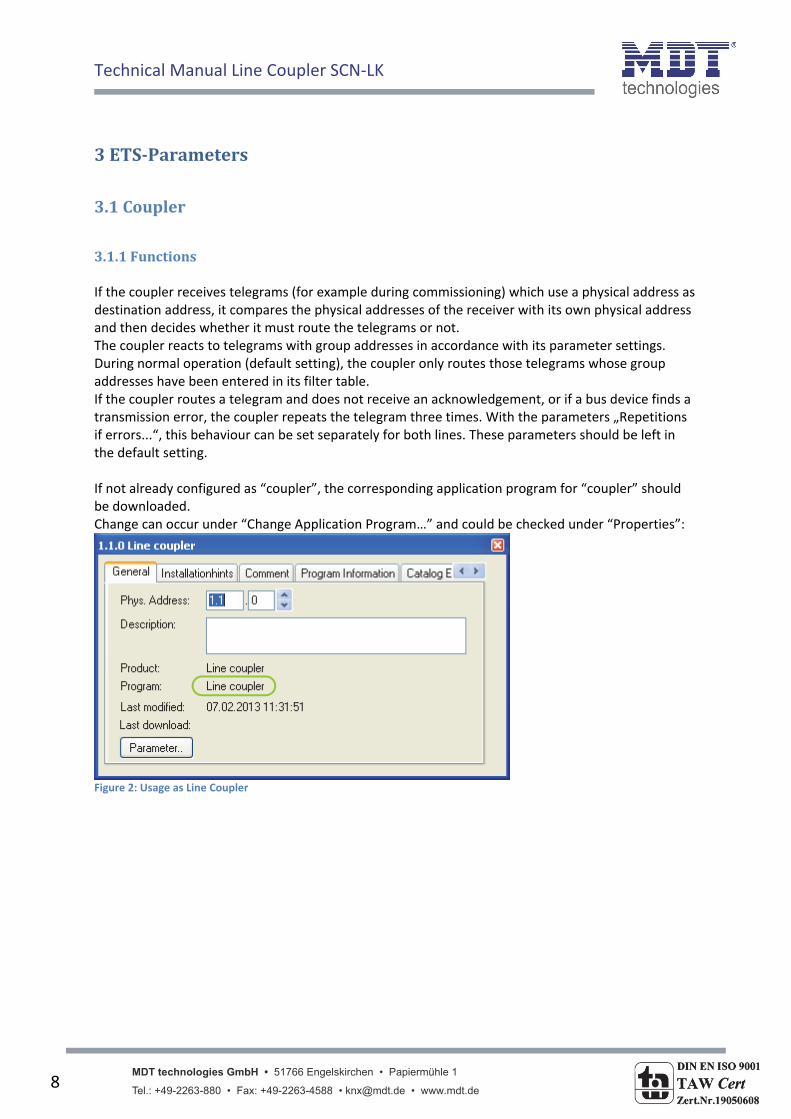
3.1.1Functions If the coupler receives telegrams (for example during commissioning) which use a physical address as destination address, it compares the physical addresses of the receiver with its own physical address and then decides whether it must route the telegrams or not. The coupler reacts to telegrams with group addresses in accordance with its parameter settings. During normal operation (default setting), the coupler only routes those telegrams whose group addresses have been entered in its filter table. If the coupler routes a telegram and does not receive an acknowledgement, or if a bus device finds a transmission error, the coupler repeats the telegram three times. With the parameters „Repetitions if errors...“, this behaviour can be set separately for both lines. These parameters should be left in the default setting. If not already configured as “coupler”, the corresponding application program for “coupler” should be downloaded. Change can occur under “Change Application Program…” and could be checked under “Properties”:
Figure 2: Usage as Line Coupler

Technical Manual Line Coupler SCN‐LK
MDT technologies GmbH • 51766 Engelskirchen • Papiermühle 1 Tel.: +49-2263-880 • Fax: +49-2263-4588 • [email protected] • www.mdt.de
9
3.1.2General
Figure 3: Line Coupler ‐ General settings
The following chart shows the available settings for the submenu “General”:
ETS‐text Dynamic range [default value]
comment
Fallback time for manual operation
10 min 1 hour 4 hours 8 hours
Time duration required to exit from “manual operation”
Manual function
Disabled Pass all telegrams Pass physical telegrams Pass group telegrams
Telegram routing configuration for the manual function.
Table 1: Line Coupler ‐ General settings
NOTE: Please note that the parameter “transmit all” for Group or Physical telegrams is intended only for testing purposes and it should not be set for normal operation.
Technical Manual Line Coupler SCN‐LK
MDT technologies GmbH • 51766 Engelskirchen • Papiermühle 1 Tel.: +49-2263-880 • Fax: +49-2263-4588 • [email protected] • www.mdt.de
10
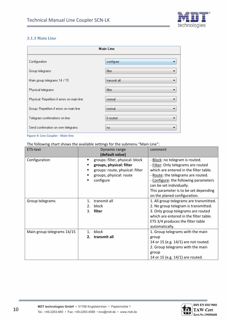
3.1.3MainLine
Figure 4: Line Coupler ‐ Main line
The following chart shows the available settings for the submenu “Main Line”:
ETS‐text Dynamic range [default value]
comment
Configuration
groups: filter, physical: block groups, physical: filter groups: route, physical: filter groups, physical: route configure
‐ Block: no telegram is routed. ‐ Filter: Only telegrams are routed which are entered in the filter table. ‐ Route: the telegrams are routed. ‐ Configure: the following parameters can be set individually. This parameter is to be set depending on the planed configuration.
Group telegrams 1. transmit all 2. block 3. filter
1. All group telegrams are transmitted.2. No group telegram is transmitted. 3. Only group telegrams are routed which are entered in the filter table. ETS 3/4 produces the filter table automatically.
Main group telegrams 14/15 1. block 2. transmit all
1. Group telegrams with the main group 14 or 15 (e.g. 14/1) are not routed. 2. Group telegrams with the main group 14 or 15 (e.g. 14/1) are routed.
Technical Manual Line Coupler SCN‐LK
MDT technologies GmbH • 51766 Engelskirchen • Papiermühle 1 Tel.: +49-2263-880 • Fax: +49-2263-4588 • [email protected] • www.mdt.de
11
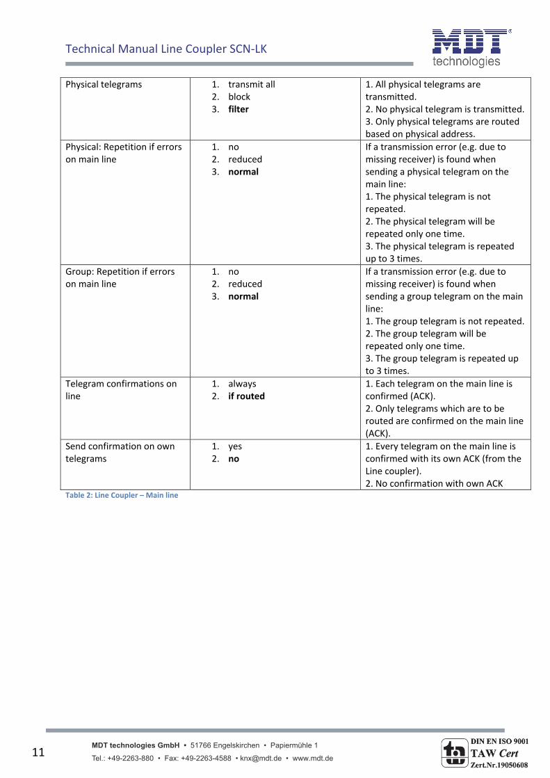
Physical telegrams 1. transmit all 2. block 3. filter
1. All physical telegrams are transmitted. 2. No physical telegram is transmitted. 3. Only physical telegrams are routed based on physical address.
Physical: Repetition if errors on main line
1. no 2. reduced 3. normal
If a transmission error (e.g. due to missing receiver) is found when sending a physical telegram on the main line: 1. The physical telegram is not repeated. 2. The physical telegram will be repeated only one time. 3. The physical telegram is repeated up to 3 times.
Group: Repetition if errors on main line
1. no 2. reduced 3. normal
If a transmission error (e.g. due to missing receiver) is found when sending a group telegram on the main line: 1. The group telegram is not repeated. 2. The group telegram will be repeated only one time. 3. The group telegram is repeated up to 3 times.
Telegram confirmations on line
1. always 2. if routed
1. Each telegram on the main line is confirmed (ACK). 2. Only telegrams which are to be routed are confirmed on the main line (ACK).
Send confirmation on own telegrams
1. yes 2. no
1. Every telegram on the main line is confirmed with its own ACK (from the Line coupler). 2. No confirmation with own ACK
Table 2: Line Coupler – Main line
Technical Manual Line Coupler SCN‐LK
MDT technologies GmbH • 51766 Engelskirchen • Papiermühle 1 Tel.: +49-2263-880 • Fax: +49-2263-4588 • [email protected] • www.mdt.de
12
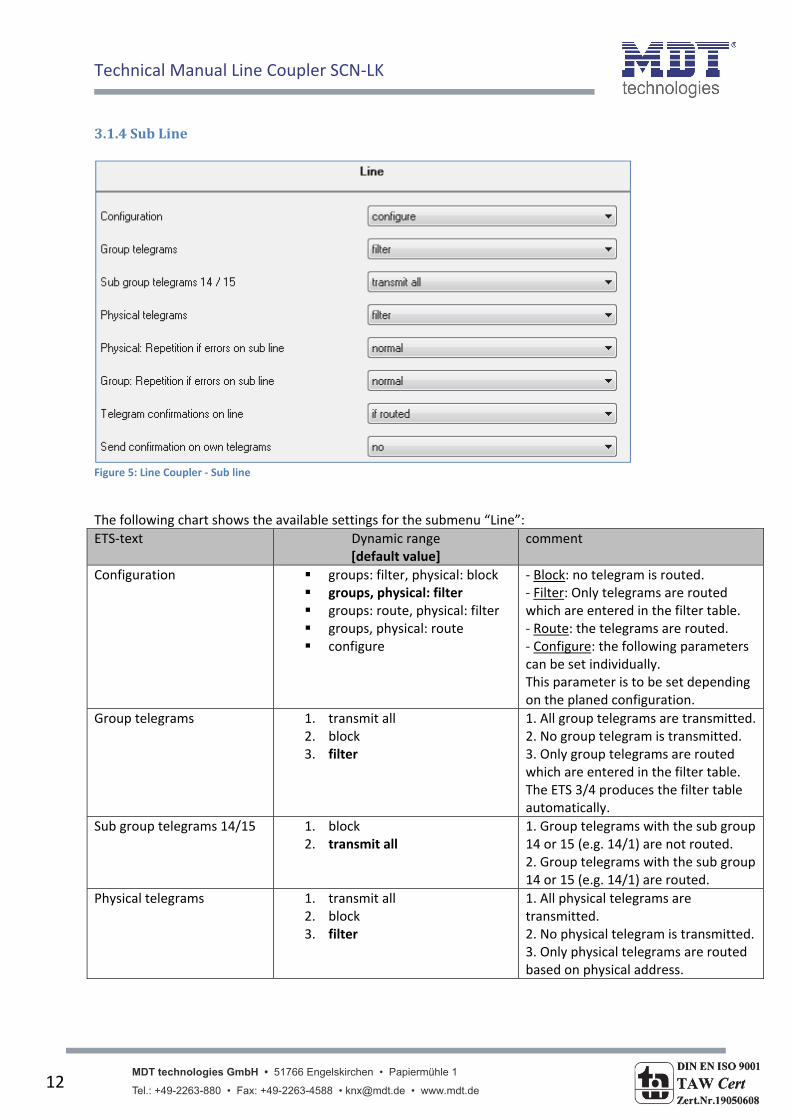
3.1.4SubLine
Figure 5: Line Coupler ‐ Sub line
The following chart shows the available settings for the submenu “Line”:
ETS‐text Dynamic range [default value]
comment
Configuration groups: filter, physical: block groups, physical: filter groups: route, physical: filter groups, physical: route configure
‐ Block: no telegram is routed. ‐ Filter: Only telegrams are routed which are entered in the filter table. ‐ Route: the telegrams are routed. ‐ Configure: the following parameters can be set individually. This parameter is to be set depending on the planed configuration.
Group telegrams 1. transmit all 2. block 3. filter
1. All group telegrams are transmitted.2. No group telegram is transmitted. 3. Only group telegrams are routed which are entered in the filter table. The ETS 3/4 produces the filter table automatically.
Sub group telegrams 14/15 1. block 2. transmit all
1. Group telegrams with the sub group14 or 15 (e.g. 14/1) are not routed. 2. Group telegrams with the sub group14 or 15 (e.g. 14/1) are routed.
Physical telegrams 1. transmit all 2. block 3. filter
1. All physical telegrams are transmitted. 2. No physical telegram is transmitted. 3. Only physical telegrams are routed based on physical address.
Technical Manual Line Coupler SCN‐LK
MDT technologies GmbH • 51766 Engelskirchen • Papiermühle 1 Tel.: +49-2263-880 • Fax: +49-2263-4588 • [email protected] • www.mdt.de
13
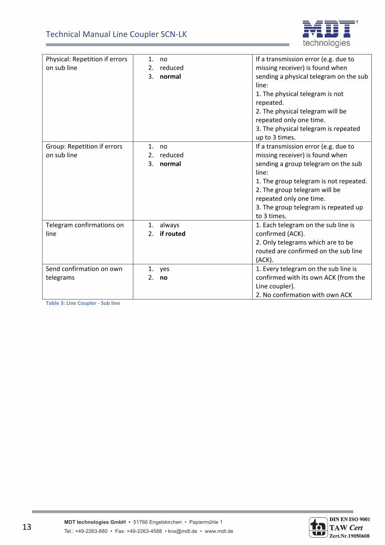
Physical: Repetition if errors on sub line
1. no 2. reduced 3. normal
If a transmission error (e.g. due to missing receiver) is found when sending a physical telegram on the sub line: 1. The physical telegram is not repeated. 2. The physical telegram will be repeated only one time. 3. The physical telegram is repeated up to 3 times.
Group: Repetition if errors on sub line
1. no 2. reduced 3. normal
If a transmission error (e.g. due to missing receiver) is found when sending a group telegram on the sub line: 1. The group telegram is not repeated. 2. The group telegram will be repeated only one time. 3. The group telegram is repeated up to 3 times.
Telegram confirmations on line
1. always 2. if routed
1. Each telegram on the sub line is confirmed (ACK). 2. Only telegrams which are to be routed are confirmed on the sub line (ACK).
Send confirmation on own telegrams
1. yes 2. no
1. Every telegram on the sub line is confirmed with its own ACK (from the Line coupler). 2. No confirmation with own ACK
Table 3: Line Coupler ‐ Sub line
Technical Manual Line Coupler SCN‐LK
MDT technologies GmbH • 51766 Engelskirchen • Papiermühle 1 Tel.: +49-2263-880 • Fax: +49-2263-4588 • [email protected] • www.mdt.de
14
3.2Repeater
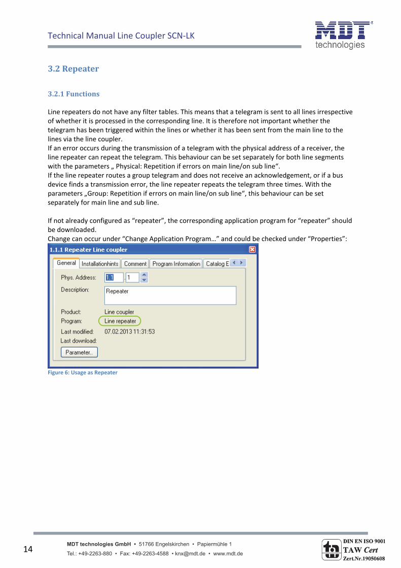
3.2.1Functions Line repeaters do not have any filter tables. This means that a telegram is sent to all lines irrespective of whether it is processed in the corresponding line. It is therefore not important whether the telegram has been triggered within the lines or whether it has been sent from the main line to the lines via the line coupler. If an error occurs during the transmission of a telegram with the physical address of a receiver, the line repeater can repeat the telegram. This behaviour can be set separately for both line segments with the parameters „ Physical: Repetition if errors on main line/on sub line“. If the line repeater routes a group telegram and does not receive an acknowledgement, or if a bus device finds a transmission error, the line repeater repeats the telegram three times. With the parameters „Group: Repetition if errors on main line/on sub line“, this behaviour can be set separately for main line and sub line. If not already configured as “repeater”, the corresponding application program for “repeater” should be downloaded. Change can occur under “Change Application Program…” and could be checked under “Properties”:
Figure 6: Usage as Repeater

Technical Manual Line Coupler SCN‐LK
MDT technologies GmbH • 51766 Engelskirchen • Papiermühle 1 Tel.: +49-2263-880 • Fax: +49-2263-4588 • [email protected] • www.mdt.de
15
3.2.2General
Figure 7: Repeater ‐ General settings
ETS‐Text
Dynamic Range [Default value]
Comment
Fallback time for manual operation
10 min, 1 hour, 4 hours, 8 hours [1 hour]
Time duration required to exit from “manual operation”
Manual function
Disabled Pass all telegrams Pass physical telegrams Pass group telegrams [pass all telegrams]
Telegram routing configuration for the manual function.
Table 4: Repeater ‐ General settings
3.2.3MainLine
Figure 8: Repeater – Main line

Technical Manual Line Coupler SCN‐LK
MDT technologies GmbH • 51766 Engelskirchen • Papiermühle 1 Tel.: +49-2263-880 • Fax: +49-2263-4588 • [email protected] • www.mdt.de
16
ETS‐Text
Dynamic Range [Default value]
Comment
Configuration groups, physical: route configure [groups, physical: route]
‐ Route: the telegrams are routed. ‐ Configure: the following parameters can be set individually. This parameter is to be set depending on the planed configuration.
Physical telegrams 1. transmit all 2. block [transmit all]
1. All physical telegrams are transmitted. 2. No physical telegram is transmitted.
Physical: Repetition if errors on main line
1. no 2. normal 3. reduced [reduced]
If a transmission error (e.g. due to missing receiver) is found when sending a physical telegram on the main line: 1. The physical telegram is not repeated. 2. The physical telegram is repeated up to 3 times. 3. The physical telegram will be repeated only one time.
Group: Repetition if errors on main line
1. no 2. normal 3. reduced [reduced]
If a transmission error (e.g. due to missing receiver) is found when sending a group telegram on the main line: 1. The group telegram is not repeated. 2. The group telegram is repeated up to 3 times. 3. The group telegram will be repeated only one time.
Telegram confirmations on line
1. if routed 2. always [always]
1. Only telegrams which are to be routed are confirmed on the main line (ACK). 2. Each telegram on the main line is confirmed (ACK).
Send confirmation on own telegrams
1. yes 2. no [yes]
1. Every telegram on the main line is confirmed with its own ACK (from the Line coupler). 2. No confirmation with own ACK
Table 5: Repeater ‐ Main line

Technical Manual Line Coupler SCN‐LK
MDT technologies GmbH • 51766 Engelskirchen • Papiermühle 1 Tel.: +49-2263-880 • Fax: +49-2263-4588 • [email protected] • www.mdt.de
17
3.2.4Subline
Figure 9: Repeater ‐ Sub line
ETS‐Text
Dynamic Range [Default value]
Comment
Configuration groups, physical: route configure [groups, physical: route]
‐ Route: the telegrams are routed. ‐ Configure: the following parameters can be set individually. This parameter is to be set depending on the planed configuration.
Physical telegrams 1. transmit all 2. block [transmit all]
1. All physical telegrams are transmitted. 2. No physical telegram is transmitted.
Physical: Repetition if errors on sub line
1. no 2. normal 3. reduced [reduced]
If a transmission error (e.g. due to missing receiver) is found when sending a physical telegram on the sub line: 1. The physical telegram is not repeated. 2. The physical telegram is repeated up to 3 times. 3. The physical telegram will be repeated only one time.
Group: Repetition if errors on sub line
1. no 2. normal 3. reduced [reduced]
If a transmission error (e.g. due to missing receiver) is found when sending a group telegram on the sub line: 1. The group telegram is not repeated. 2. The group telegram is repeated up to 3 times. 3. The group telegram will be repeated only one time.
Telegram confirmations on line
1. if routed 2. always [always]
1. Only telegrams which are to be routed are confirmed on the sub line (ACK). 2. Each telegram on the sub line is confirmed (ACK).
Send confirmation on own telegrams
1. yes 2. no [yes]
1. Every telegram on the sub line is confirmed with its own ACK (from the Line coupler). 2. No confirmation with own ACK
Table 6: Repeater ‐ Sub line
Technical Manual Line Coupler SCN‐LK
MDT technologies GmbH • 51766 Engelskirchen • Papiermühle 1 Tel.: +49-2263-880 • Fax: +49-2263-4588 • [email protected] • www.mdt.de
18
4SettingsattheETS
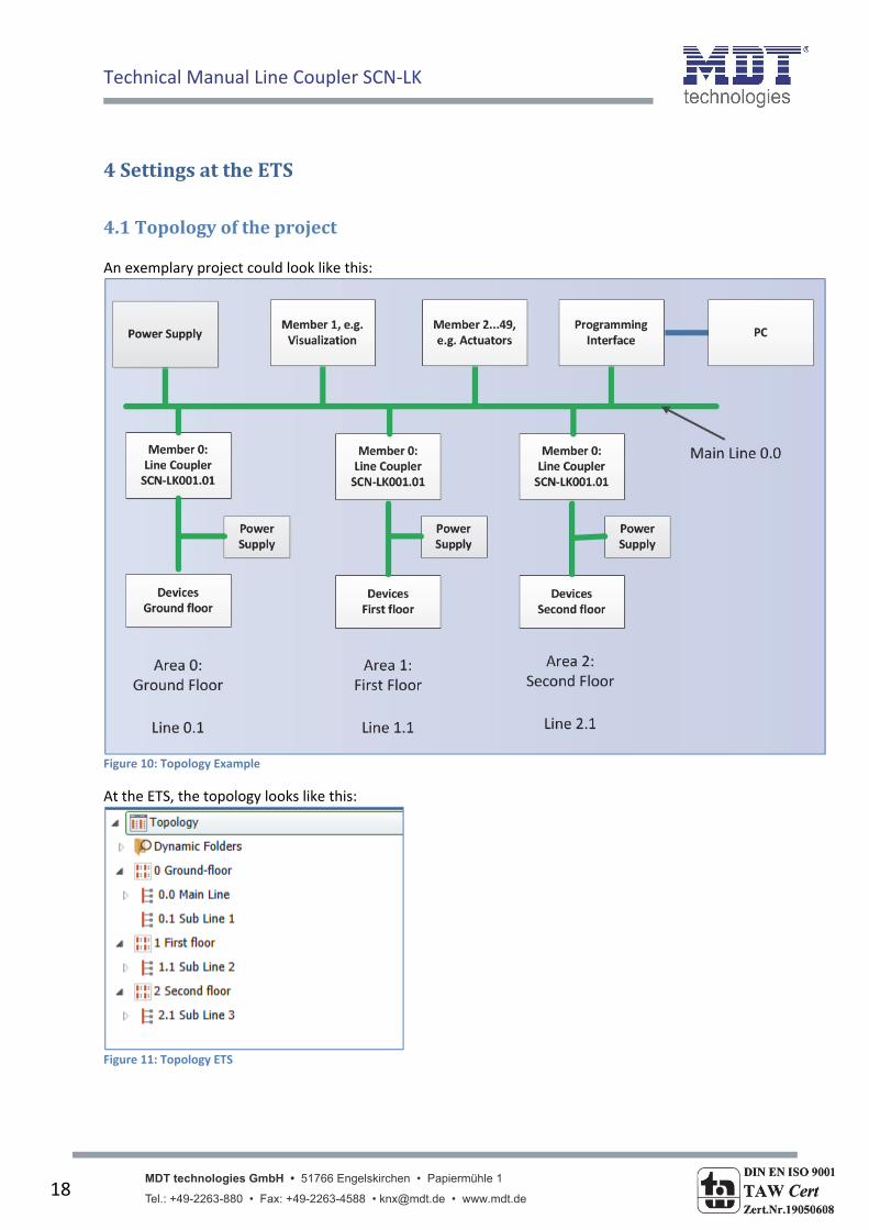
4.1Topologyoftheproject An exemplary project could look like this:
Figure 10: Topology Example
At the ETS, the topology looks like this:
Figure 11: Topology ETS
Technical Manual Line Coupler SCN‐LK
MDT technologies GmbH • 51766 Engelskirchen • Papiermühle 1 Tel.: +49-2263-880 • Fax: +49-2263-4588 • [email protected] • www.mdt.de
19
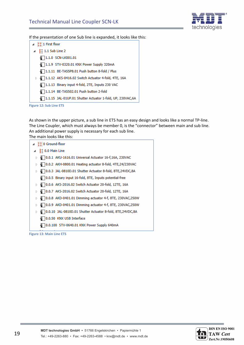
If the presentation of one Sub line is expanded, it looks like this:
Figure 12: Sub Line ETS
As shown in the upper picture, a sub line in ETS has an easy design and looks like a normal TP‐line. The Line Coupler, which must always be member 0, is the “connector” between main and sub line. An additional power supply is necessary for each sub line. The main looks like this:
Figure 13: Main Line ETS
Technical Manual Line Coupler SCN‐LK
MDT technologies GmbH • 51766 Engelskirchen • Papiermühle 1 Tel.: +49-2263-880 • Fax: +49-2263-4588 • [email protected] • www.mdt.de
20
4.2TelegramForwarding Two ways of telegram forwarding are differentiated:
1. Telegrams with physical addressing 2. Telegrams with group addressing
The addressing with physical addresses is, for example, used at the programming of the devices, whereas the addressing by group addresses is used at the “normal” bus communication. The behavior of the Line Coupler at telegrams with physical addressing is easy. If the physical target address is in the line of the Line Coupler, the telegram is forwarded else not. The behavior of the Line Coupler at group telegrams is defined by filter tables. For that matter, the filter tables indicate the group addresses, which are forwarded from main to sub line and vice versa. For doing this, the Line Coupler listens at the main line and at the sub line to all group telegrams and compares the target address with group addresses in the filter table. If the target address is in the filter table, the telegram will be forwarded to the other line else not.
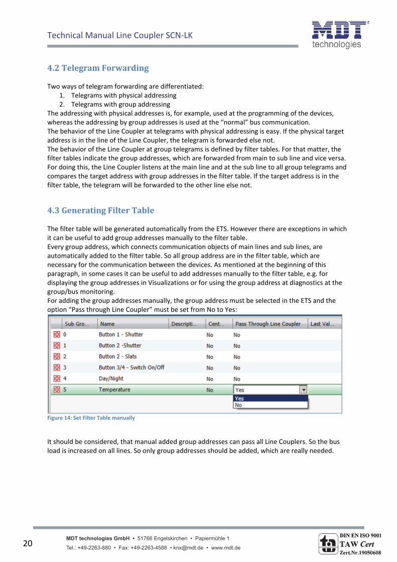
4.3GeneratingFilterTable The filter table will be generated automatically from the ETS. However there are exceptions in which it can be useful to add group addresses manually to the filter table. Every group address, which connects communication objects of main lines and sub lines, are automatically added to the filter table. So all group address are in the filter table, which are necessary for the communication between the devices. As mentioned at the beginning of this paragraph, in some cases it can be useful to add addresses manually to the filter table, e.g. for displaying the group addresses in Visualizations or for using the group address at diagnostics at the group/bus monitoring. For adding the group addresses manually, the group address must be selected in the ETS and the option “Pass through Line Coupler” must be set from No to Yes:
Figure 14: Set Filter Table manually
It should be considered, that manual added group addresses can pass all Line Couplers. So the bus load is increased on all lines. So only group addresses should be added, which are really needed.
Technical Manual Line Coupler SCN‐LK
MDT technologies GmbH • 51766 Engelskirchen • Papiermühle 1 Tel.: +49-2263-880 • Fax: +49-2263-4588 • [email protected] • www.mdt.de
21
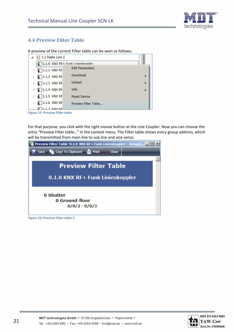
4.4PreviewFilterTable A preview of the current Filter table can be seen as follows:
Figure 15: Preview Filter table
For that purpose, you click with the right mouse button at the Line Coupler. Now you can choose the entry “Preview Filter table…” in the context menu. The Filter table shows every group address, which will be transmitted from main line to sub line and vice versa:
Figure 16: Preview Filter table 2
Technical Manual Line Coupler SCN‐LK
MDT technologies GmbH • 51766 Engelskirchen • Papiermühle 1 Tel.: +49-2263-880 • Fax: +49-2263-4588 • [email protected] • www.mdt.de
22
4.5Approachatstartup After all devices are integrated in the project, appropriate the right topology like described in4.1 Topology of the project, the devices can be parameterized according to the own wishes. It is recommended to use the SCN‐LK001.01 with the default settings. The right course of action at the startup is very important, because otherwise the exchange of data between main line and sub line cannot be guaranteed.
1. Programming the Line Coupler By programming the Line Coupler, the current settings are load into the Line Coupler. Furthermore the current Filter table is loaded into the Line Coupler.
2. Programming of the devices of the sub line By programming the devices of the sub line just the parameter settings are load in the memory of the devices.
Important: At every change of the project, the Line Coupler must be load again(Download Application). Afterwards every device, which is changed, must be programmed again. If Changes at the topology of the project are made, at first the Line Coupler must be downloaded and afterwards every device, which is involved of the change of the topology, must be downloaded again.
Technical Manual Line Coupler SCN‐LK
MDT technologies GmbH • 51766 Engelskirchen • Papiermühle 1 Tel.: +49-2263-880 • Fax: +49-2263-4588 • [email protected] • www.mdt.de
23
5Index
5.1Registerofillustrations Figure 1: Exemplary circuit diagram ........................................................................................................ 4 Figure 2: Usage as Line Coupler .............................................................................................................. 8 Figure 3: Line Coupler ‐ General settings ................................................................................................ 9 Figure 4: Line Coupler ‐ Main line ......................................................................................................... 10 Figure 5: Line Coupler ‐ Sub line ............................................................................................................ 12 Figure 6: Usage as Repeater .................................................................................................................. 14 Figure 7: Repeater ‐ General settings .................................................................................................... 15 Figure 8: Repeater – Main line .............................................................................................................. 15 Figure 9: Repeater ‐ Sub line ................................................................................................................. 17 Figure 10: Topology Example ................................................................................................................ 18 Figure 11: Topology ETS ........................................................................................................................ 18 Figure 12: Sub Line ETS .......................................................................................................................... 19 Figure 13: Main Line ETS ....................................................................................................................... 19 Figure 14: Set Filter Table manually ...................................................................................................... 20 Figure 15: Preview Filter table .............................................................................................................. 21 Figure 16: Preview Filter table 2 ............................................................................................................ 21
5.2Listoftables Table 1: Line Coupler ‐ General settings ................................................................................................. 9 Table 2: Line Coupler – Main line .......................................................................................................... 11 Table 3: Line Coupler ‐ Sub line ............................................................................................................. 13 Table 4: Repeater ‐ General settings ..................................................................................................... 15 Table 5: Repeater ‐ Main line ................................................................................................................ 16 Table 6: Repeater ‐ Sub line .................................................................................................................. 17
Technical Manual Line Coupler SCN‐LK
MDT technologies GmbH • 51766 Engelskirchen • Papiermühle 1 Tel.: +49-2263-880 • Fax: +49-2263-4588 • [email protected] • www.mdt.de
24
6 Attachment
6.1 Statutory requirements
The above‐described devices must not be used with devices, which serve directly or indirectly the
purpose of human, health‐ or lifesaving. Further the devices must not be used if their usage can
occur danger for humans, animals or material assets.
Do not let the packaging lying around careless, plastic foil/ ‐bags etc. can be a dangerous toy for kids.
6.2 Routine disposal
Do not throw the waste equipment in the household rubbish. The device contains electrical devices,
which must be disposed as electronic scrap. The casing contains of recyclable synthetic material.
6.3 Assemblage
Risk for life of electrical power!
All activities on the device should only be done by an electrical specialist. The county specific
regulations and the applicable EIB‐directives have to be observed.
MDT USB/IP Interface
SCN-USBR.01 SCN-LK001.01
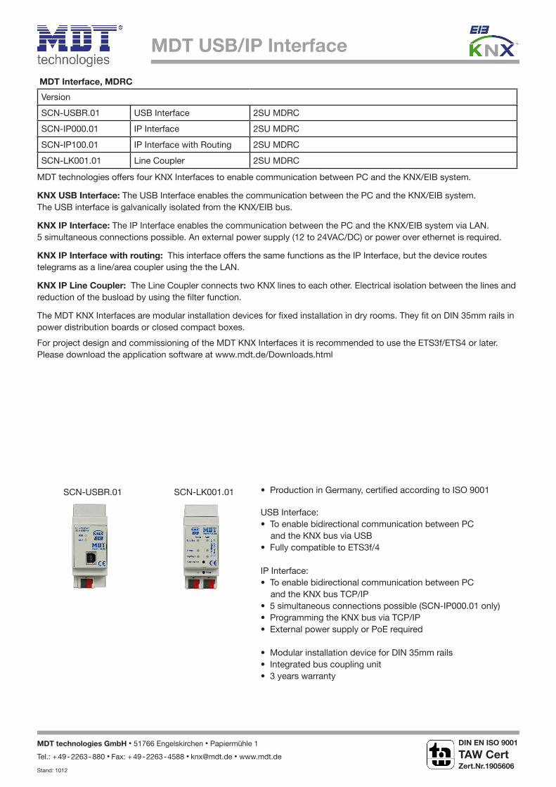
MDT Interface, MDRC
Version
SCN-USBR.01 USB Interface 2SU MDRC
SCN-IP000.01 IP Interface 2SU MDRC
SCN-IP100.01 IP Interface with Routing 2SU MDRC
SCN-LK001.01 Line Coupler 2SU MDRC
MDT technologies offers four KNX Interfaces to enable communication between PC and the KNX/EIB system.
KNX USB Interface: The USB Interface enables the communication between the PC and the KNX/EIB system. The USB interface is galvanically isolated from the KNX/EIB bus.
KNX IP Interface: The IP Interface enables the communication between the PC and the KNX/EIB system via LAN. 5 simultaneous connections possible. An external power supply (12 to 24VAC/DC) or power over ethernet is required.
KNX IP Interface with routing: This interface offers the same functions as the IP Interface, but the device routes telegrams as a line/area coupler using the the LAN.
KNX IP Line Coupler: The Line Coupler connects two KNX lines to each other. Electrical isolation between the lines and reduction of the busload by using the filter function.
The MDT KNX Interfaces are modular installation devices for fixed installation in dry rooms. They fit on DIN 35mm rails in power distribution boards or closed compact boxes.
For project design and commissioning of the MDT KNX Interfaces it is recommended to use the ETS3f/ETS4 or later. Please download the application software at www.mdt.de/Downloads.html
USB Interface:• To enable bidirectional communication between PC and the KNX bus via USB• Fully compatible to ETS3f/4
IP Interface:• To enable bidirectional communication between PC and the KNX bus TCP/IP• 5 simultaneous connections possible (SCN-IP000.01 only)• Programming the KNX bus via TCP/IP• External power supply or PoE required
• Modular installation device for DIN 35mm rails• Integrated bus coupling unit • 3 years warranty
• Production in Germany, certified according to ISO 9001
MDT technologies GmbH • 51766 Engelskirchen • Papiermühle 1
Tel.: + 49 - 2263 - 880 • Fax: + 49 - 2263 - 4588 • [email protected] • www.mdt.de
Stand: 1012
DIN EN ISO 9001
TAW Cert Zert.Nr.1905606
N
MDT USB/IP Interface
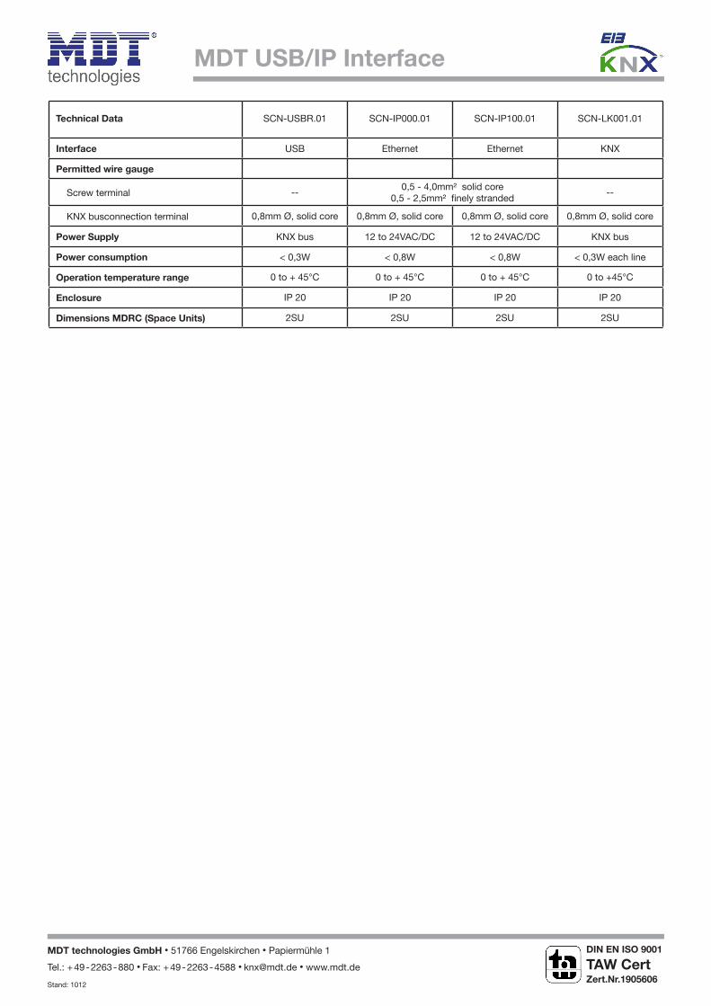
Technical Data SCN-USBR.01 SCN-IP000.01 SCN-IP100.01 SCN-LK001.01
Interface USB Ethernet Ethernet KNX
Permitted wire gauge
Screw terminal --0,5 - 4,0mm² solid core
0,5 - 2,5mm² finely stranded--
KNX busconnection terminal 0,8mm Ø, solid core 0,8mm Ø, solid core 0,8mm Ø, solid core 0,8mm Ø, solid core
Power Supply KNX bus 12 to 24VAC/DC 12 to 24VAC/DC KNX bus
Power consumption < 0,3W < 0,8W < 0,8W < 0,3W each line
Operation temperature range 0 to + 45°C 0 to + 45°C 0 to + 45°C 0 to +45°C
Enclosure IP 20 IP 20 IP 20 IP 20
Dimensions MDRC (Space Units) 2SU 2SU 2SU 2SU
MDT technologies GmbH • 51766 Engelskirchen • Papiermühle 1
Tel.: + 49 - 2263 - 880 • Fax: + 49 - 2263 - 4588 • [email protected] • www.mdt.de
Stand: 1012
DIN EN ISO 9001
TAW Cert Zert.Nr.1905606
N