technical design calculation report clt_en.pdf · en 14080 timber structures - glued laminated...
TRANSCRIPT

TECHNICAL DESIGN CALCULATION REPORT
Design Of Timber Structures
Project: Residential building
Location: Villazzano City: Trento
Address: Via della Villa , 22/A Province: Trento
Client: TimberTech s.r.l.
Building company: TimberTech s.r.l.
Structural designer: TimberTech s.r.l.
Date: Thursday, July 2, 2015

Technical Design Calculation Report TimberTech s.r.l.
www.timbertech.it
Technical Design Calculation Report TimberTech s.r.l.
www.timbertech.it
Design codes and standards 1. EN 1993-1-1 – Eurocode 3
Design of steel structures - Part 1-1: General rules and rules for buildings
2. EN 1993-1-8 – Eurocode 3
Design of steel structures - Part 1-8: Design of joints
3. EN 1995-1-1 – Eurocode 5
Design of timber structures - Part 1-1: General - Common rules and rules for buildings
4. EN 338
Structural timber - Strength classes
5. EN 1194
Timber structures - Glued laminated timber - Strength classes and determination of characteristic values
6. EN 14080
Timber structures - Glued laminated timber and glued solid timber - Requirements


Technical Design Calculation Report TimberTech s.r.l.
www.timbertech.it
General description of the building
Location Region: Trentino-alto Adige
Province: Trento
City: Trento
Place: Villazzano
Address: Via della Villa, 22/A
Latitude: 46.06°
Longitude: 11.11°
Elevation mamsl: 193 m
Description Number of storeys: 2
Building length: 12.92 m
Building width: 17.3 m
Building height: 7.7 m

Technical Design Calculation Report TimberTech s.r.l.
www.timbertech.it
Three-dimensional view Southeast
Technical Design Calculation Report TimberTech s.r.l.
www.timbertech.it
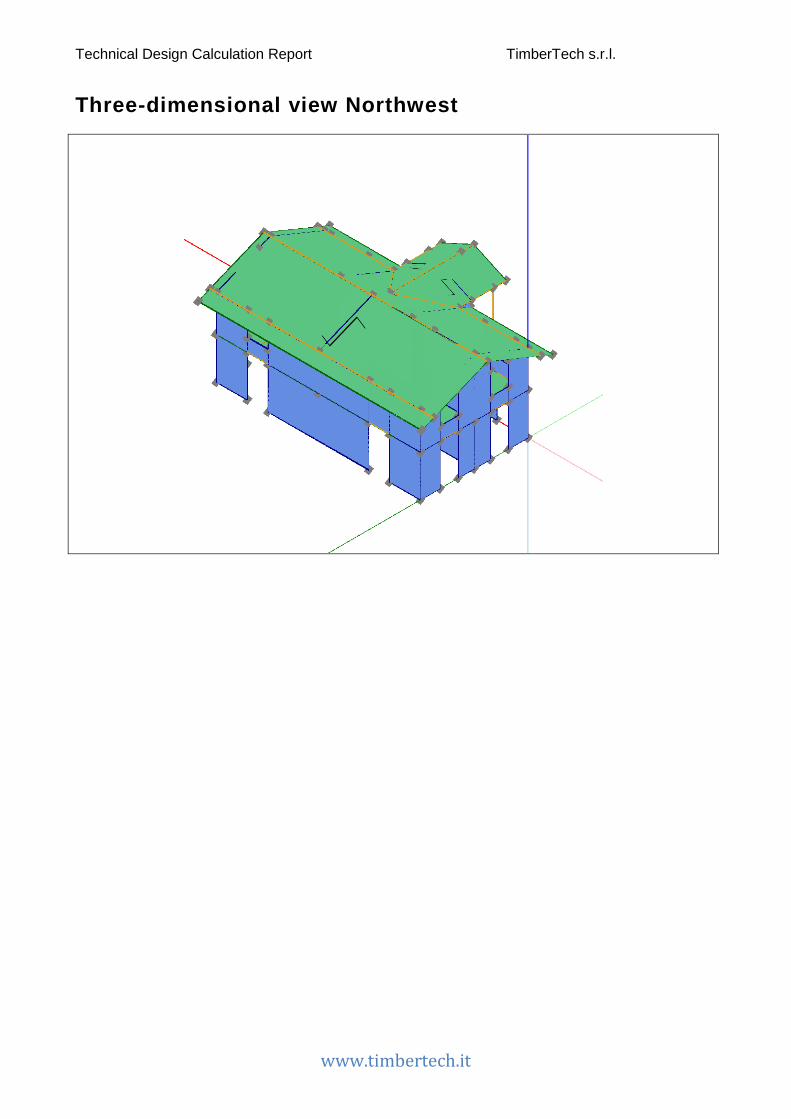
Three-dimensional view Northwest

Technical Design Calculation Report TimberTech s.r.l.
www.timbertech.it
Three-dimensional view South West

Technical Design Calculation Report TimberTech s.r.l.
www.timbertech.it
Three-dimensional view North East


Technical Design Calculation Report TimberTech s.r.l.
www.timbertech.it
Calculation software used
Calculation software features The software used is TimberTech Buildings, developed by Timber Tech s.r.l., start-up of the University of Trento (Italy).
Technical specifications
Name: TimberTech Buildings
Version: 2.20150622.1646R
Software Producer: Timber Tech s.r.l.
Via della Villa, 22/A
I-38123 – Villazzano – Trento (TN) – Italy
www.timbertech.it
License registered to Timber Tech s.r.l.


Technical Design Calculation Report TimberTech s.r.l.
www.timbertech.it
Materials
Wooden materials The materials used in the project are listed in the following tables.
Descr. Description
𝑓𝑓𝑚𝑚,𝑘𝑘 Characteristic bending strength
𝑓𝑓𝑡𝑡,0,𝑘𝑘 Characteristic tensile strength along the grain
𝑓𝑓𝑡𝑡,90,𝑘𝑘 Characteristic tensile strength perpendicular to the grain
𝑓𝑓𝑐𝑐,0,𝑘𝑘 Characteristic compressive strength along the grain
𝑓𝑓𝑐𝑐,90,𝑘𝑘 Characteristic compressive strength perpendicular to the grain
𝑓𝑓𝑣𝑣,𝑘𝑘 Characteristic shear strength
𝐸𝐸0,𝑚𝑚𝑚𝑚𝑚𝑚𝑚𝑚 Mean value of modulus of elasticity along the grain
𝐸𝐸0,05 Fifth percentile value of modulus of elasticity along the grain
𝐸𝐸90,𝑚𝑚𝑚𝑚𝑚𝑚𝑚𝑚 Mean value of modulus of elasticity perpendicular to the grain
𝐺𝐺𝑚𝑚𝑚𝑚𝑚𝑚𝑚𝑚 Mean value of shear modulus
𝜌𝜌𝑘𝑘 Characteristic density
𝑓𝑓𝑣𝑣,𝑘𝑘,𝑖𝑖𝑚𝑚𝑖𝑖𝑖𝑖𝑚𝑚𝑚𝑚𝑚𝑚 Characteristic in-plane shear strength of CLT panel
𝑓𝑓𝑅𝑅,𝑘𝑘 Characteristic rolling shear strength
𝑓𝑓𝑇𝑇,𝑘𝑘 Torsional resistance of the glued interfaces
𝐺𝐺𝑅𝑅,𝑚𝑚𝑚𝑚𝑚𝑚𝑚𝑚 Mean value of rolling shear modulus
Homogeneous glued-laminated timber
Descr. 𝐟𝐟𝐦𝐦,𝐤𝐤 [MPa]
𝒇𝒇𝒕𝒕,𝟎𝟎,𝒌𝒌 [MPa]
𝒇𝒇𝒕𝒕,𝟗𝟗𝟎𝟎,𝒌𝒌 [MPa]
𝒇𝒇𝒄𝒄,𝟎𝟎,𝒌𝒌 [MPa]
𝒇𝒇𝒄𝒄,𝟗𝟗𝟎𝟎,𝒌𝒌 [MPa]
𝒇𝒇𝒗𝒗,𝒌𝒌 [MPa]
𝑬𝑬𝟎𝟎,𝒎𝒎𝒎𝒎𝒎𝒎𝒎𝒎 [MPa]
𝑬𝑬𝟎𝟎,𝟎𝟎𝟎𝟎 [MPa]
𝑬𝑬𝟗𝟗𝟎𝟎,𝒎𝒎𝒎𝒎𝒎𝒎𝒎𝒎 [MPa]
𝑮𝑮𝒎𝒎𝒎𝒎𝒎𝒎𝒎𝒎 [MPa]
𝝆𝝆𝒌𝒌 [kg/m3]
GL 24h 24 19.2 0.5 24 2.5 3.5 11500 9600 300 650 385

Technical Design Calculation Report TimberTech s.r.l.
www.timbertech.it
CLT
Descr 𝒇𝒇𝒎𝒎,𝒌𝒌 [MPa]
𝒇𝒇𝒕𝒕,𝟎𝟎,𝒌𝒌 [MPa]
𝒇𝒇𝒕𝒕,𝟗𝟗𝟎𝟎,𝒌𝒌 [MPa]
𝒇𝒇𝒄𝒄,𝟎𝟎,𝒌𝒌 [MPa]
𝒇𝒇𝒄𝒄,𝟗𝟗𝟎𝟎,𝒌𝒌 [MPa]
𝒇𝒇𝒗𝒗,𝒌𝒌,𝒑𝒑𝒑𝒑𝒎𝒎𝒑𝒑𝒕𝒕 [MPa]
𝒇𝒇𝑹𝑹,𝒌𝒌
[MPa]
𝒇𝒇𝒗𝒗,𝒌𝒌,𝒍𝒍𝒎𝒎𝒑𝒑𝒕𝒕𝒍𝒍 [MPa]
𝒇𝒇𝑻𝑻,𝒌𝒌
[MPa]
𝑬𝑬𝟎𝟎,𝒎𝒎𝒎𝒎𝒎𝒎𝒎𝒎 [MPa]
𝑬𝑬𝟎𝟎,𝟎𝟎𝟎𝟎 [MPa]
𝑬𝑬𝟗𝟗𝟎𝟎,𝒎𝒎𝒎𝒎𝒎𝒎𝒎𝒎 [MPa]
𝑮𝑮𝒎𝒎𝒎𝒎𝒎𝒎𝒎𝒎 [MPa]
𝑮𝑮𝑹𝑹,𝒎𝒎𝒎𝒎𝒎𝒎𝒎𝒎 [MPa]
𝝆𝝆𝒌𝒌 [kg/m3]
C 24 XLAM 24 14 0.4 21 2.5 4 0.8 4 2.5 11000 7400 370 690 50 350
C 24 XLAM 24 14 0.4 21 2.5 4 0.8 4 2.5 11000 7400 370 690 50 350
Screws
Manufacturer Code Descr. Type l [mm]
d1 [mm]
d2 [mm]
𝒇𝒇𝒖𝒖𝒌𝒌 [MPa]
HBS 10 x 120 HBS10120 HBS 10 x 120 0 120 10 6.4 1000

Technical Design Calculation Report TimberTech s.r.l.
www.timbertech.it
Calculation method and numerical model
Model Description Hypothesis adopted for the elements
The timber walls are constrained at the base by means of connection systems capable of transmitting both in-plane and out-of-plane actions.
The floors are schematized simply supported by the walls or by the beams and the columns are modelled with hinged ends.
The horizontal elements are considered infinitely rigid in their plane and with three degrees of freedom: two translational and one rotational.
In the analysis, in presence of horizontal loads, some elements may be defined as “secondary”: this mean that their strength and stiffness are neglected in the calculation of the response of the building. In the model these elements are represented in terms of mass and they are designed only for vertical loads.
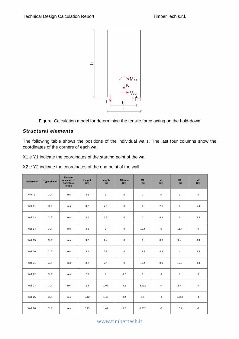
Rigid body rocking – Forces on hold-down / tie-down
The hold-down or tie-down systems are used to prevent the rotation of the wall caused by the overturning moment of the horizontal force. The hold-down, placed on the in-tension edge of the wall, is loaded by a force equal to
𝑇𝑇 = � �𝑀𝑀3−3
𝑏𝑏−𝑁𝑁2� ⋅
1𝑛𝑛𝑚𝑚𝑚𝑚𝑐𝑐
𝑓𝑓𝑓𝑓𝑓𝑓 𝑎𝑎𝑎𝑎𝑎𝑎𝑎𝑎𝑎𝑎𝑎𝑎 ℎ𝑓𝑓𝑜𝑜𝑜𝑜 − 𝑜𝑜𝑓𝑓𝑑𝑑𝑛𝑛
0 𝑓𝑓𝑓𝑓𝑓𝑓 𝑎𝑎𝑛𝑛𝑎𝑎𝑎𝑎𝑎𝑎𝑎𝑎𝑎𝑎𝑎𝑎 ℎ𝑓𝑓𝑜𝑜𝑜𝑜 − 𝑜𝑜𝑓𝑓𝑑𝑑𝑛𝑛
where:
𝑏𝑏 is the lever arm for the internal couple, assumed equal to 0.9 ⋅ 𝑜𝑜, where 𝑜𝑜 is the length of the wall
𝑁𝑁 is the axial vertical load acting on the wall
𝑀𝑀3−3 is the moment acting in the plane of the wall
𝑛𝑛𝑚𝑚𝑚𝑚𝑐𝑐 is the number of connections present at each corner of the wall
Technical Design Calculation Report TimberTech s.r.l.
www.timbertech.it
Figure: Calculation model for determining the tensile force acting on the hold-down
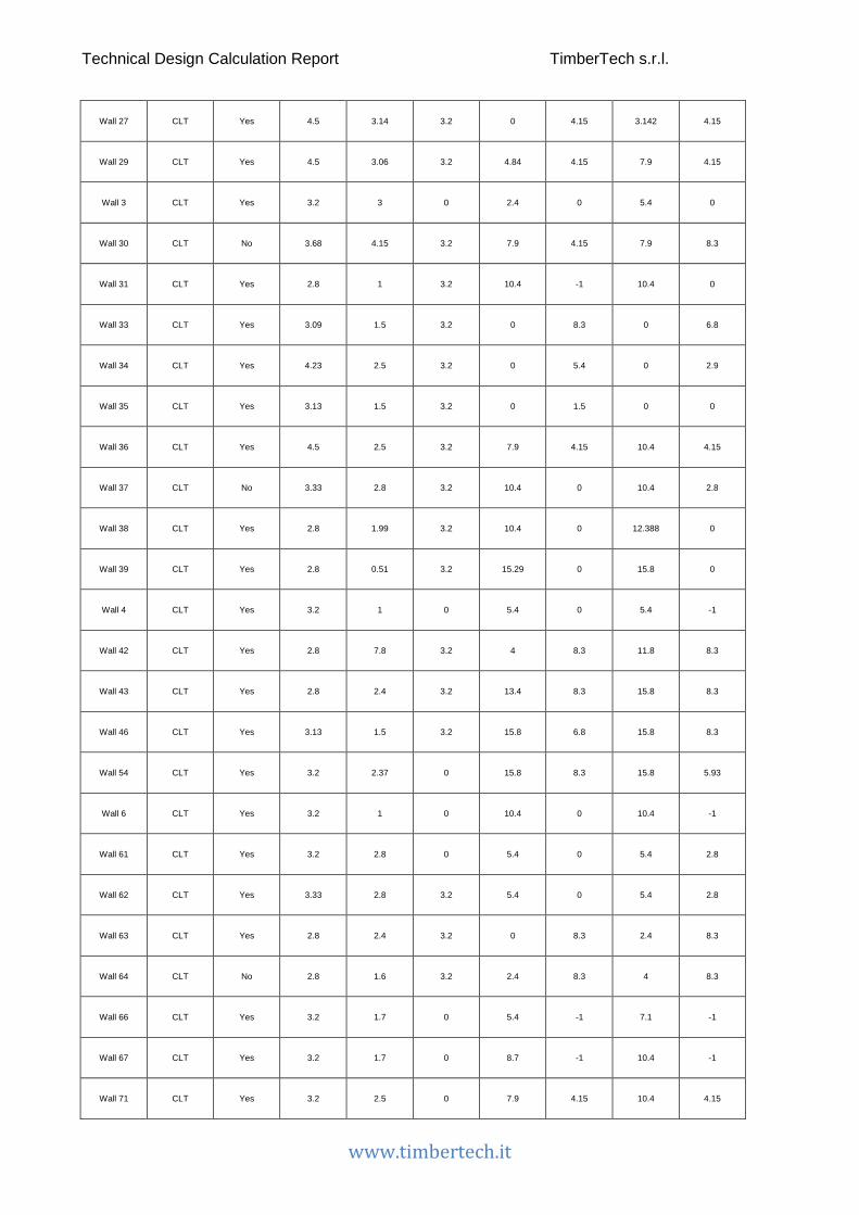
Structural elements
The following table shows the positions of the individual walls. The last four columns show the coordinates of the corners of each wall.
X1 e Y1 indicate the coordinates of the starting point of the wall
X2 e Y2 indicate the coordinates of the end point of the wall
Wall name Type of wall Element
resistant to horizontal
loads
Height [m]
Length [m]
Altitude [m]
X1 [m]
Y1 [m]
X2 [m]
Y2 [m]
Wall 1 CLT Yes 3.2 1 0 0 0 1 0
Wall 11 CLT Yes 3.2 2.5 0 0 2.9 0 5.4
Wall 13 CLT Yes 3.2 1.5 0 0 6.8 0 8.3
Wall 14 CLT Yes 3.2 3 0 10.4 0 13.4 0
Wall 15 CLT Yes 3.2 2.4 0 0 8.3 2.4 8.3
Wall 20 CLT Yes 3.2 7.8 0 11.8 8.3 4 8.3
Wall 21 CLT Yes 3.2 2.4 0 13.4 8.3 15.8 8.3
Wall 22 CLT Yes 2.8 1 3.2 0 0 1 0
Wall 23 CLT Yes 2.8 1.99 3.2 3.412 0 5.4 0
Wall 25 CLT Yes 3.12 1.47 3.2 5.4 -1 6.868 -1
Wall 26 CLT Yes 3.15 1.47 3.2 8.932 -1 10.4 -1
Technical Design Calculation Report TimberTech s.r.l.
www.timbertech.it
Wall 27 CLT Yes 4.5 3.14 3.2 0 4.15 3.142 4.15
Wall 29 CLT Yes 4.5 3.06 3.2 4.84 4.15 7.9 4.15
Wall 3 CLT Yes 3.2 3 0 2.4 0 5.4 0
Wall 30 CLT No 3.68 4.15 3.2 7.9 4.15 7.9 8.3
Wall 31 CLT Yes 2.8 1 3.2 10.4 -1 10.4 0
Wall 33 CLT Yes 3.09 1.5 3.2 0 8.3 0 6.8
Wall 34 CLT Yes 4.23 2.5 3.2 0 5.4 0 2.9
Wall 35 CLT Yes 3.13 1.5 3.2 0 1.5 0 0
Wall 36 CLT Yes 4.5 2.5 3.2 7.9 4.15 10.4 4.15
Wall 37 CLT No 3.33 2.8 3.2 10.4 0 10.4 2.8
Wall 38 CLT Yes 2.8 1.99 3.2 10.4 0 12.388 0
Wall 39 CLT Yes 2.8 0.51 3.2 15.29 0 15.8 0
Wall 4 CLT Yes 3.2 1 0 5.4 0 5.4 -1
Wall 42 CLT Yes 2.8 7.8 3.2 4 8.3 11.8 8.3
Wall 43 CLT Yes 2.8 2.4 3.2 13.4 8.3 15.8 8.3
Wall 46 CLT Yes 3.13 1.5 3.2 15.8 6.8 15.8 8.3
Wall 54 CLT Yes 3.2 2.37 0 15.8 8.3 15.8 5.93
Wall 6 CLT Yes 3.2 1 0 10.4 0 10.4 -1
Wall 61 CLT Yes 3.2 2.8 0 5.4 0 5.4 2.8
Wall 62 CLT Yes 3.33 2.8 3.2 5.4 0 5.4 2.8
Wall 63 CLT Yes 2.8 2.4 3.2 0 8.3 2.4 8.3
Wall 64 CLT No 2.8 1.6 3.2 2.4 8.3 4 8.3
Wall 66 CLT Yes 3.2 1.7 0 5.4 -1 7.1 -1
Wall 67 CLT Yes 3.2 1.7 0 8.7 -1 10.4 -1
Wall 71 CLT Yes 3.2 2.5 0 7.9 4.15 10.4 4.15

Technical Design Calculation Report TimberTech s.r.l.
www.timbertech.it
Wall 72 CLT Yes 3.2 3.06 0 4.84 4.15 7.9 4.15
Wall 72 CLT Yes 3.2 3.14 0 0 4.15 3.142 4.15
Wall 73 CLT Yes 2.8 1 3.2 5.4 0 5.4 -1
Wall 74 CLT No 1.0 2.41 3.2 1 0 3.412 0
Wall 75 CLT No 1.0 1.4 3.2 0 6.8 0 5.4
Wall 76 CLT No 1.0 1.4 3.2 0 2.9 0 1.5
Wall 77 CLT No 1.0 1.6 3.2 13.4 8.3 11.8 8.3
Wall 78 CLT No 1.0 1.73 3.2 15.8 6.8 15.8 5.074
Wall 8 CLT Yes 3.2 0.6 0 15.2 0 15.8 0
Wall 9 CLT Yes 3.2 1.5 0 0 0 0 1.5
Wall2 CLT No 3.77 5.07 3.2 15.8 0 15.8 5.074
Wall3 CLT Yes 3.2 2.8 0 15.8 0 15.8 2.8
The following table shows the positions of the columns.
X e Y are the coordinates of the point where the column is located
Column name
Height [m]
Altitude [m]
X [m]
Y [m]
Column 1 3.2 0 5.4 -2.7
Column 10 3.95 3.2 7.9 -2.7
Column 11 3.2 0 13.4 4.15
Column 12 3.95 3.2 7.9 2.8
Column 2 3.2 0 7.9 -2.7
Column 3 3.2 0 10.4 -2.7
Column 6 4.5 3.2 15.8 4.15
Column 7 2.8 3.2 5.4 -2.7
Column 9 2.8 3.2 10.4 -2.7

Technical Design Calculation Report TimberTech s.r.l.
www.timbertech.it
Wall horizontal stiffness The wall stiffness can be estimated considering the contributions of all the components, as shown below.
CLT walls
The overall stiffness of CLTwalls is calculated taking into account the contribution of the following components:
• CLT panel (kXLAM)
• shear connections – angle brackets (ka)
• hold-down or tie-down (kh)
Figure: Mechanical model for determining the CLT walls overall stiffness
The following table indicates the positions of the walls and their equivalent shear stiffness.
Wall name Type of wall Element
resistant to horizontal
loads
Height [m]
Length [m]
Equivalent shear
stiffness [kN/m]
Wall 1 CLT Yes 3.2 1 1049
Wall 11 CLT Yes 3.2 2.5 5663
Wall 13 CLT Yes 3.2 1.5 3194
Technical Design Calculation Report TimberTech s.r.l.
www.timbertech.it
Wall 14 CLT Yes 3.2 3 5237
Wall 15 CLT Yes 3.2 2.4 4176
Wall 20 CLT Yes 3.2 7.8 18323
Wall 21 CLT Yes 3.2 2.4 4176
Wall 22 CLT Yes 2.8 1 1110
Wall 23 CLT Yes 2.8 1.99 3867
Wall 25 CLT Yes 3.12 1.47 1827
Wall 26 CLT Yes 3.15 1.47 1795
Wall 27 CLT Yes 4.5 3.14 3968
Wall 29 CLT Yes 4.5 3.06 3785
Wall 3 CLT Yes 3.2 3 5237
Wall 30 CLT No 3.68 4.15 0
Wall 31 CLT Yes 2.8 1 1110
Wall 33 CLT Yes 3.09 1.5 1990
Wall 34 CLT Yes 4.23 2.5 2909
Wall 35 CLT Yes 3.13 1.5 1943
Wall 36 CLT Yes 4.5 2.5 2604
Wall 37 CLT No 3.33 2.8 0
Wall 38 CLT Yes 2.8 1.99 3867

Technical Design Calculation Report TimberTech s.r.l.
www.timbertech.it
Wall 39 CLT Yes 2.8 0.51 294
Wall 4 CLT Yes 3.2 1 2784
Wall 42 CLT Yes 2.8 7.8 39023
Wall 43 CLT Yes 2.8 2.4 4717
Wall 46 CLT Yes 3.13 1.5 1943
Wall 54 CLT Yes 3.2 2.37 5460
Wall 6 CLT Yes 3.2 1 1651
Wall 61 CLT Yes 3.2 2.8 7528
Wall 62 CLT Yes 3.33 2.8 5406
Wall 63 CLT Yes 2.8 2.4 5464
Wall 64 CLT No 2.8 1.6 0
Wall 66 CLT Yes 3.2 1.7 2978
Wall 67 CLT Yes 3.2 1.7 2978
Wall 71 CLT Yes 3.2 2.5 3723
Wall 72 CLT Yes 3.2 3.06 5429
Wall 72 CLT Yes 3.2 3.14 5695
Wall 73 CLT Yes 2.8 1 1110
Wall 74 CLT No 1.0 2.41 0
Wall 75 CLT No 1.0 1.4 0
Technical Design Calculation Report TimberTech s.r.l.
www.timbertech.it
Wall 76 CLT No 1.0 1.4 0
Wall 77 CLT No 1.0 1.6 0
Wall 78 CLT No 1.0 1.73 0
Wall 8 CLT Yes 3.2 0.6 389
Wall 9 CLT Yes 3.2 1.5 3194
Wall2 CLT No 3.77 5.07 0
Wall3 CLT Yes 3.2 2.8 5749
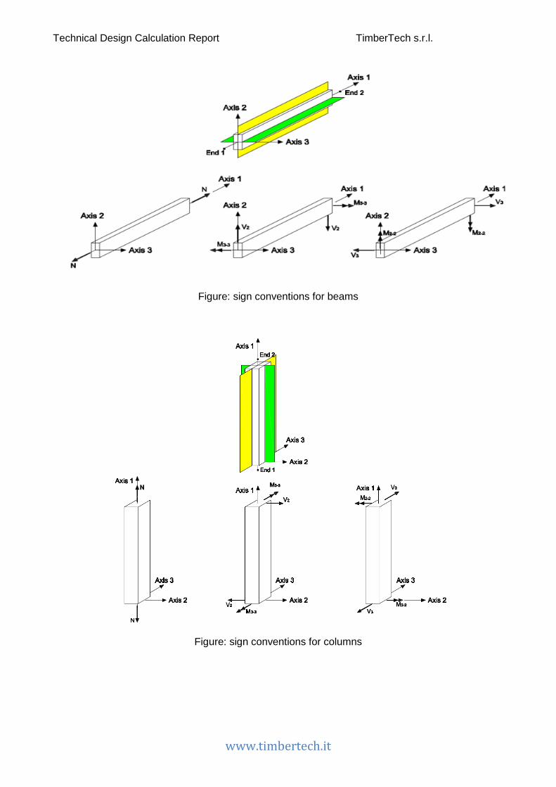
Types of structural elements and sign conventions Linear elements
The linear elements are used to model beams and columns. They have a local reference system with respect to which stress/force components are shown. The sign convention adopted is shown in the figure below.
Force Description Unit of measure N Axial force kN
M3-3 Bending moment about local axis 3 kN m V2 Shear along local axis 2 kN
M2-2 Bending moment about local axis 2 kN m V3 Shear along local axis 3 kN
Technical Design Calculation Report TimberTech s.r.l.
www.timbertech.it
Figure: sign conventions for beams
Figure: sign conventions for columns

Technical Design Calculation Report TimberTech s.r.l.
www.timbertech.it
Wall elements
The walls, regardless of type, have the following sign conventions.
Stress Description Unit of measure
In-plane stresses n Axial stress (per unit length) kN/m
m3-3 Bending moment about local axis 3 (per unit length) kNm/m v2 Shear along local axis 2 (per unit length) kN/m
Out-of-plane stresses (plate)
m2-2 Bending moment about local axis 2 (per unit length) kNm/m v3 Shear along local axis 3 (per unit length) kN/m
Force Description Unit of measure
In-plane stresses N Total axial force kN
M3-3 Bending moment about local axis 3 kNm V2 Shear along local axis 2 kN
Out-of-plane stresses (plate)
M2-2 Bending moment about local axis 3 kNm V3 Shear along local axis 2 kN
Figure: sign conventions for walls

Technical Design Calculation Report TimberTech s.r.l.
www.timbertech.it
Actions and design loads
Self-weight of structural materials The weights of the structural materials are shown in the table below.
Description Specific weight ɣ [kN/m3]
GL 24h 6 C 24 XLAM 6
Snow loads The snow load is evaluated in accordance with the Italian Standard (3.4 - NTC ‘08).
Snow load on the roof can be evaluated using expression 3.3.7 NTC ‘08
𝑞𝑞𝑠𝑠 = 𝜇𝜇𝑖𝑖 ⋅ 𝑞𝑞𝑠𝑠𝑘𝑘 ⋅ 𝐶𝐶𝐸𝐸 ⋅ 𝐶𝐶𝑡𝑡
where
𝑞𝑞𝑠𝑠 is the value of the snow load on the roof
𝜇𝜇𝑖𝑖 is the shape coefficient
𝑞𝑞𝑠𝑠𝑘𝑘 is the characteristic ground snow load
𝐶𝐶𝐸𝐸 is the exposure coefficient
𝐶𝐶𝑡𝑡 is the thermal coefficient
Characteristic ground snow load at the site
Province: Trento
Elevation mamsl: 193 m
Snow load zone: Zone I - Alpine
Characteristic ground snow load: 1.50 kN/m2
Topographic category: Normal topography :
Exposure coefficient: 1
Thermal coefficient: 1
Snow is not prevented from sliding off: No

Technical Design Calculation Report TimberTech s.r.l.
www.timbertech.it
Snow load on the roof
The value of the snow load acting on each roof is shown in the following table.
Roof name Snow load [kN/m2]
Floor 3 1.20 Floor 14 1.20
Wind actions The wind load is evaluated in accordance with the Italian standard (section 3.3 of NTC ’08). The wind action is represented by a simplified set of pressures or forces whose effects are equivalent to the extreme effects of the turbulent wind. For the usual structures the wind action are considered as equivalent static actions evaluated as described in § 3.3.3 NTC ‘08.
Project data
Province: Trento
Elevation mamsl: 193 m
Wind load zone: Zone 1
Terrain roughness class: Class A
Distance from the coast: Hinterland
Exposure category: V
Reference mean (basic) velocity
The fundamental value of the basic wind velocity, vb, is the characteristic 10 minutes mean wind velocity, irrespective of wind direction and time of year, at 10 m above ground level in terrain with exposure category II (Tab. 3.3.II) and referring to a return period of 50 years.
The value of the basic wind velocity 𝑎𝑎𝑏𝑏 is given by the expression:
𝑎𝑎𝑏𝑏 = 𝑎𝑎𝑏𝑏,0 for as ≤ a0
𝑎𝑎𝑏𝑏 = 𝑎𝑎𝑏𝑏,0 + 𝑘𝑘𝑚𝑚 ⋅ (𝑎𝑎𝑠𝑠 − 𝑎𝑎0) for a0 < as ≤ 1500 m
where:
𝑎𝑎𝑏𝑏,0, 𝑎𝑎0, 𝑘𝑘𝑚𝑚 are factors which are dependent on the site where the building is located (Fig. 3.3.1.)
𝑎𝑎𝑠𝑠 is the altitude above sea level (in m) of the site where the building is located.
𝑎𝑎𝑏𝑏,0 25 m/s
𝑎𝑎0 1000 m

Technical Design Calculation Report TimberTech s.r.l.
www.timbertech.it
𝑘𝑘𝑚𝑚 0.010 1/s
Reference velocity: 25.00 m/s
Reference velocity pressure
The reference velocity pressure qb (in N/m²) is given by the expression:
𝑞𝑞𝑏𝑏 =12⋅ 𝜌𝜌 ⋅ 𝑎𝑎𝑏𝑏2
where
𝑎𝑎𝑏𝑏 is the reference velocity of the wind (in m/s);
𝜌𝜌 is the air density conventionally assumed constant and equal to 1,25 kg/m3.
So
𝑞𝑞𝑏𝑏 390.63 N/m2
Wind pressure acting on the building surfaces
The wind pressure acting on the building surfaces is given by the following expression
𝑝𝑝 = 𝑞𝑞𝑏𝑏 ⋅ 𝑎𝑎𝑚𝑚 ⋅ 𝑎𝑎𝑖𝑖 ⋅ 𝑎𝑎𝑑𝑑
where
𝑞𝑞𝑏𝑏 is reference velocity pressure
𝑎𝑎𝑚𝑚 is the exposure factor depending on the height z on the ground; it can be calculated with the following expression:
𝑎𝑎𝑚𝑚(𝑧𝑧) = 𝑘𝑘𝑟𝑟2 ⋅ 𝑎𝑎𝑡𝑡 ⋅ ln � 𝑧𝑧𝑧𝑧0� ⋅ �7 + 𝑎𝑎𝑡𝑡 ⋅ ln � 𝑧𝑧
𝑧𝑧0�� for z ≥ zmin
𝑎𝑎𝑚𝑚(𝑧𝑧) = 𝑎𝑎𝑚𝑚(𝑧𝑧min) for z<zmin
where
𝑎𝑎𝑡𝑡 is the topography factor
𝑎𝑎𝑖𝑖 is the pressure coefficient
𝑎𝑎𝑑𝑑 is the dynamic factor which takes into account the increasing effect from vibrations due to turbulence
The values assumed in the calculations for the coefficients mentioned above are reported in the following tables.
Description Value
Dynamic factor 1

Technical Design Calculation Report TimberTech s.r.l.
www.timbertech.it
Figure: Values of the coefficient cpe depending on the inclination of the surface.
Below are the values of cpe e cpi. The internal pressure coefficient, which gives the effect of the wind on the internal surfaces of buildings, is equal to zero if the building is airtight, conversely it is equal to ±0.2 if the building has openings. Internal and external pressures are considered to act at the same time. The worst combination of external and internal pressures are considered for every combination of possible openings.
Building element Inclined at an angle [°] cpe Windward wall 90 0.8 Leeward wall 90 -0.4
Leeward roof pitch - -0.4 Windward pitch 22° 22 -0.33
Type of construction cpi Airtight 0

Technical Design Calculation Report TimberTech s.r.l.
www.timbertech.it
Loads acting on the walls The following table shows the loads acting on the walls.
Load name: Load ID
Position: Position of the wall: internal or external
g1,k: Permanent action: self-weight
g2,k: Permanent action
q,wind,k: Variable actions: wind load
Wall name Position Load name g1,k [kN/m2]
g2,k [kN/m2]
q,wind,k downwind
[kN/m2]
q,wind,k windward
[kN/m2]
Wall 1 External External wall load 0.6 0.6 -0.23 0.46
Wall 3 External External wall load 0.6 0.6 -0.23 0.46
Wall 4 External External wall load 0.6 0.6 -0.23 0.46
Wall 6 External External wall load 0.6 0.6 -0.23 0.46
Wall 8 External External wall load 0.6 0.6 -0.23 0.46
Wall 9 External External wall load 0.6 0.6 -0.23 0.46
Wall 11 External External wall load 0.6 0.6 -0.23 0.46
Wall 13 External External wall load 0.6 0.6 -0.23 0.46
Wall 14 External External wall load 0.6 0.6 -0.23 0.46
Wall 15 External External wall load 0.6 0.6 -0.23 0.46
Wall 20 External External wall load 0.6 0.6 -0.23 0.46
Wall 21 External External wall load 0.6 0.6 -0.23 0.46
Wall 22 External External wall load 0.6 0.6 -0.23 0.46
Wall 23 External External wall load 0.6 0.6 -0.23 0.46
Wall 25 External External wall load 0.6 0.6 -0.23 0.46
Wall 26 External External wall load 0.6 0.6 -0.23 0.46
Wall 27 External External wall load 0.6 0.6 -0.23 0.46

Technical Design Calculation Report TimberTech s.r.l.
www.timbertech.it
Wall 29 External External wall load 0.6 0.6 -0.23 0.46
Wall 30 External External wall load 0.6 0.6 -0.23 0.46
Wall 31 External External wall load 0.6 0.6 -0.23 0.46
Wall 33 External External wall load 0.6 0.6 -0.23 0.46
Wall 34 External External wall load 0.6 0.6 -0.23 0.46
Wall 35 External External wall load 0.6 0.6 -0.23 0.46
Wall 36 External External wall load 0.6 0.6 -0.23 0.46
Wall 37 External External wall load 0.6 0.6 -0.23 0.46
Wall 38 External External wall load 0.6 0.6 -0.23 0.46
Wall 39 External External wall load 0.6 0.6 -0.23 0.46
Wall 42 External External wall load 0.6 0.6 -0.23 0.46
Wall 43 External External wall load 0.6 0.6 -0.23 0.46
Wall 46 External External wall load 0.6 0.6 -0.23 0.46
Wall 54 External External wall load 0.6 0.6 -0.23 0.46
Wall 61 External External wall load 0.6 0.6 -0.23 0.46
Wall 62 External External wall load 0.6 0.6 -0.23 0.46
Wall 63 External External wall load 0.6 0.6 -0.23 0.46
Wall 64 External External wall load 0.6 0.6 -0.23 0.46
Wall 66 External External wall load 0.6 0.6 -0.23 0.46
Wall 67 External External wall load 0.6 0.6 -0.23 0.46
Wall 71 External External wall load 0.6 0.6 -0.23 0.46
Wall 72 External External wall load 0.6 0.6 -0.23 0.46
Wall 72 External External wall load 0.6 0.6 -0.23 0.46
Wall 73 External External wall load 0.6 0.6 -0.23 0.46
Wall 74 External External wall load 0.6 0.6 -0.23 0.46
Wall 75 External External wall load 0.6 0.6 -0.23 0.46

Technical Design Calculation Report TimberTech s.r.l.
www.timbertech.it
Wall 76 External External wall load 0.6 0.6 -0.23 0.46
Wall 77 External External wall load 0.6 0.6 -0.23 0.46
Wall 78 External External wall load 0.6 0.6 -0.23 0.46
Wall2 External External wall load 0.6 0.6 -0.23 0.46
Wall3 External External wall load 0.6 0.6 -0.23 0.46
Loads acting on the floors The following table shows the characteristic values of the loads acting on the decks.
Load name: Load ID
Position: Position of the floor: internal or external
Environment: Load category
α: Roof pitch angle
g1,k: Permanent action: self-weight
g2,k: Permanent action
q,k: Variable actions
q,snow,k: Variable actions: snow load
q,wind,k: Variable actions: wind load
Floor name Position α [°] Load name Environment g1,k
[kN/m2] g2,k
[kN/m2] q,k
[kN/m2] q,snow,k [kN/m2]
q,wind,k leeward [kN/m2]
q,wind,k windward
[kN/m2]
Floor 1 Internal floor 0 Residential
environment load
Live loads cat. A - Residential rooms and related services, hotels
0.7 2 2 0 0 0
Floor 3 Roof 22 Roof load
Live loads cat. H1 - Roofs accessible only for maintenance and
repair
0.38 2 0.5 1.2 -0.23 -0.19
Floor 12 Internal floor 25 Residential
environment load
Live loads cat. A - Residential rooms and related services, hotels
0.38 2 2 0 0 0
Floor 13 Internal floor 25 Residential
environment load
Live loads cat. A - Residential rooms and related services, hotels
0.38 2 2 0 0 0
Floor 14 Roof 22 Roof load
Live loads cat. H1 - Roofs accessible only for maintenance and
repair
0.38 2 0.5 1.2 -0.23 -0.19
Floor 15 Internal floor 0 Residential
environment load
Live loads cat. A - Residential rooms and related services, hotels
0.7 2 2 0 0 0
Technical Design Calculation Report TimberTech s.r.l.
www.timbertech.it
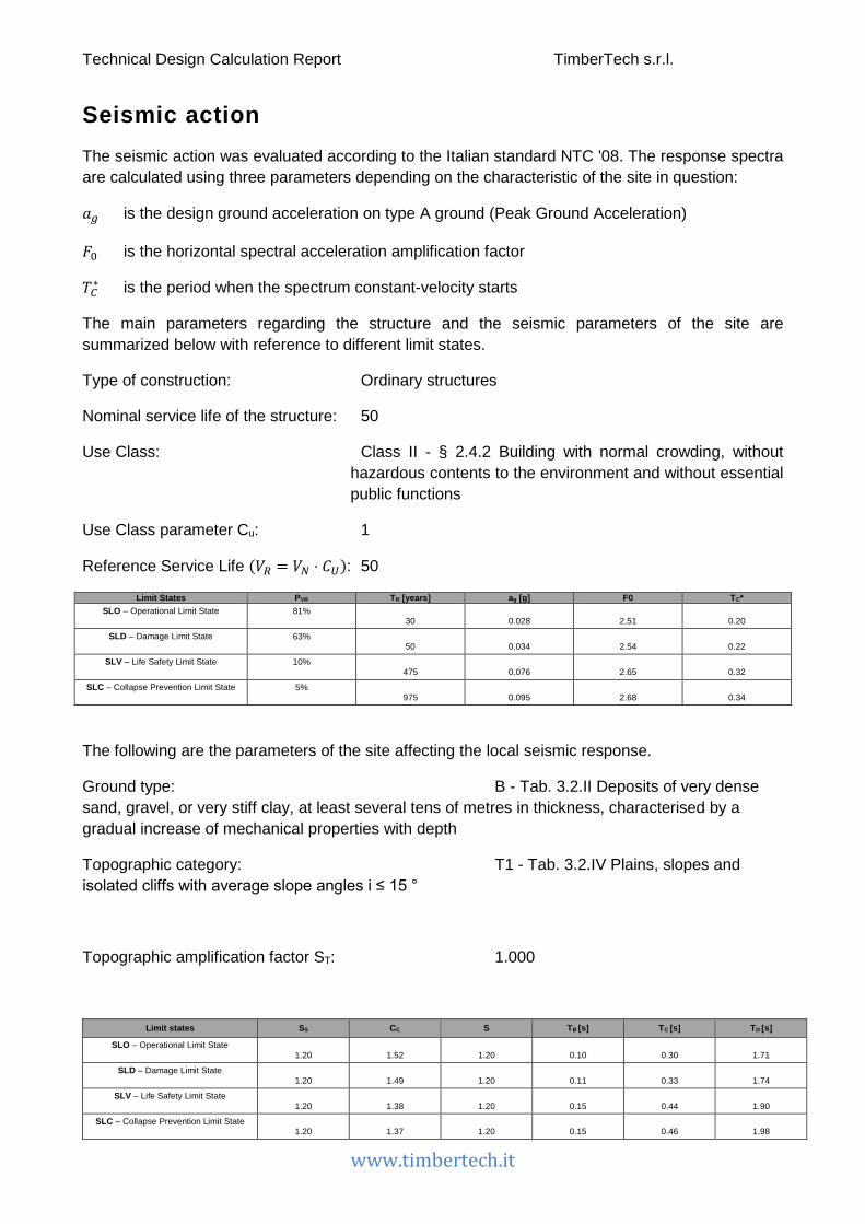
Seismic action The seismic action was evaluated according to the Italian standard NTC '08. The response spectra are calculated using three parameters depending on the characteristic of the site in question:
𝑎𝑎𝑔𝑔 is the design ground acceleration on type A ground (Peak Ground Acceleration)
𝐹𝐹0 is the horizontal spectral acceleration amplification factor
𝑇𝑇𝐶𝐶∗ is the period when the spectrum constant-velocity starts
The main parameters regarding the structure and the seismic parameters of the site are summarized below with reference to different limit states.
Type of construction: Ordinary structures
Nominal service life of the structure: 50
Use Class: Class II - § 2.4.2 Building with normal crowding, without hazardous contents to the environment and without essential public functions
Use Class parameter Cu: 1
Reference Service Life (𝑉𝑉𝑅𝑅 = 𝑉𝑉𝑁𝑁 ⋅ 𝐶𝐶𝑈𝑈): 50
Limit States PVR TR [years] ag [g] F0 TC* SLO – Operational Limit State
81%
30
0.028
2.51
0.20
SLD – Damage Limit State
63%
50
0.034
2.54
0.22
SLV – Life Safety Limit State
10%
475
0.076
2.65
0.32
SLC – Collapse Prevention Limit State
5%
975
0.095
2.68
0.34
The following are the parameters of the site affecting the local seismic response.
Ground type: B - Tab. 3.2.II Deposits of very dense sand, gravel, or very stiff clay, at least several tens of metres in thickness, characterised by a gradual increase of mechanical properties with depth
Topographic category: T1 - Tab. 3.2.IV Plains, slopes and isolated cliffs with average slope angles i ≤ 15 °
Topographic amplification factor ST: 1.000
Limit states SS CC S TB [s] TC [s] TD [s]
SLO – Operational Limit State
1.20
1.52
1.20
0.10
0.30
1.71
SLD – Damage Limit State
1.20
1.49
1.20
0.11
0.33
1.74
SLV – Life Safety Limit State
1.20
1.38
1.20
0.15
0.44
1.90
SLC – Collapse Prevention Limit State
1.20
1.37
1.20
0.15
0.46
1.98
Technical Design Calculation Report TimberTech s.r.l.
www.timbertech.it
where
S is the Soil Factor
Ss stratigraphic amplification factor
CC a coefficient depending on the category of subsoil
TB is the period when the plateau at constant acceleration of the spectrum starts
TC is the period when this plateau ends
TD is the value defining the beginning of the constant displacement response range
of the spectrum
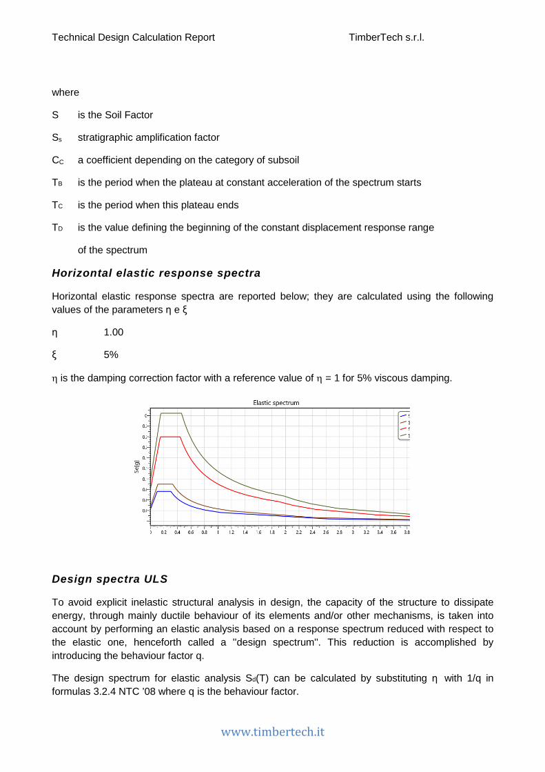
Horizontal elastic response spectra
Horizontal elastic response spectra are reported below; they are calculated using the following values of the parameters η e ξ
η 1.00
ξ 5%
η is the damping correction factor with a reference value of η = 1 for 5% viscous damping.
Design spectra ULS
To avoid explicit inelastic structural analysis in design, the capacity of the structure to dissipate energy, through mainly ductile behaviour of its elements and/or other mechanisms, is taken into account by performing an elastic analysis based on a response spectrum reduced with respect to the elastic one, henceforth called a ''design spectrum''. This reduction is accomplished by introducing the behaviour factor q.
The design spectrum for elastic analysis Sd(T) can be calculated by substituting η with 1/q in formulas 3.2.4 NTC ’08 where q is the behaviour factor.

Technical Design Calculation Report TimberTech s.r.l.
www.timbertech.it
𝑞𝑞 = 𝑞𝑞0 ⋅ 𝐾𝐾𝑅𝑅
KR is a reduction factor of the value of the behaviour factor q for buildings non-regular in elevation
Below are the parameters relating to the characteristics of the building:
Elevation Regularity: Yes
KR: 1.0
Ductility class: Ductility class "B"
Structural typology: Glued wall panels - Tab. 7.7.I Glued wall panels with glued diaphragms, connected with nails and bolts
Base value of the behavior factor q0: 2.00
Behaviour factor q: 2.00
The horizontal elastic response spectra and the horizontal design spectrum (Life Safety Limit State) are shown below.

Technical Design Calculation Report TimberTech s.r.l.
www.timbertech.it
Sections of the structural elements
CLT walls The following table shows the CLT walls characteristics.
Section name Manufacturer Panel name Material Layers
number Thickness
[mm] Layers Orientation of
the outer layers
CLT 120 mm - 5 layers -
vertical joints Predefinito 100 5s T C 24 XLAM 5 100 20 - 20 - 20 -
20 - 20 Vertical
CLT 100 mm - 3 layers Predefinito 100 3s T C 24 XLAM 3 100 30 - 40 - 30 Vertical
The characteristics of the walls with vertical joints between the CLT panels are summarized below.
Section name Type of joint between the
panels
Length of the single panel
bp [mm] Metal
fastener Spacing of
the fasteners sc [mm]
CLT 120 mm - 5 layers -
vertical joints
Inclined screws 1250 HBS 10 x 120 250
Figure: Vertical wall panels joint – joint with inclined screws

Technical Design Calculation Report TimberTech s.r.l.
www.timbertech.it
Floors with timber joists Elements geometric characteristics
hb: Cross section height
bb: Cross section width
ib: Joists spacing
The following table sets out the details concerning the floor with joists. Section name Material Cross section height hb [mm] Cross section width bb [mm] Joists spacing ib [mm]
Joist floor 160x240 GL 24h 240 160 600
CLT floors Floor geometric characteristic
hb: CLT panel thickness
The following table sets out the details concerning the CLT floors.
Section name Manufacturer CLT panel name Material Number of
layers Thickness
hb[mm] Layers External layers
orientation
CLT floor Predefinito 140 5s L C 24 XLAM 5 140 40 - 20 - 20 - 20 - 40
Parallel to the calculation direction
Figure: geometric characteristics of the floor
Figure: CLT floor geometric characteristics

Technical Design Calculation Report TimberTech s.r.l.
www.timbertech.it
Cross section of timber linear elements The following table sets out the details concerning the cross section of every linear element.
Section name Material Width b [mm] Height h [mm] Area A [mm2] Jy-y [mm4] Jz-z [mm4] Section 200x240 GL
24h GL 24h 200 240 48000 2.30E8 1.60E8
Section 200x440 GL 24h GL 24h 200 440 88000 1.42E9 2.93E8
Section 200x520 GL 24h GL 24h 200 520 104000 2.34E9 3.47E8
Figure: Geometric size of every timber cross section
Connections Hold Down
Figure: graphical representation of a hold-down in a base connection (timber wall – foundation connection)
Technical Design Calculation Report TimberTech s.r.l.
www.timbertech.it
Connection name
Connection position
Manufacturer Description Fasteners
number Fastener typology Anchor Type of
anchor Anchorage
depth [mm]
Number of hold-down at
each wall end
Ground connection - hold down - shear angle
bracket
Ground connection Rotho Blass WHT 440 20 Chiodi Anker
4,0 X 40 M16 5.8 Resina
vinilestere ETA-09/0078
160 1
Ground connection - hold down - shear angle
bracket 3
Ground connection Rotho Blass WHT 540 42 Chiodi Anker
4,0 X 60 M16 5.8 Resina
vinilestere ETA-09/0078
160 2
Ground connection - hold down - shear angle
bracket 2
Ground connection Rotho Blass WHT 540 42 Chiodi Anker
4,0 X 60 M16 5.8 Resina
vinilestere ETA-09/0078
160 1
Ground connection - hold down - shear angle
bracket 4
Ground connection Rotho Blass WHT 620 52 Chiodi Anker
4,0 X 60 M20 5.8 Resina
vinilestere ETA-09/0078
200 2
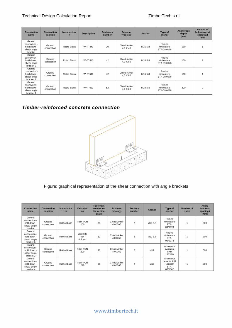
Timber-reinforced concrete connection
Figure: graphical representation of the shear connection with angle brackets
Connection name
Connection position
Manufacturer
Description
Fasteners number on the vertical
plate
Fastener typology
Anchors number Anchor Type of
anchor Number of
sides
Angle brackets spacing i
[mm] Ground
connection - hold down - shear angle
bracket
Ground connection Rotho Blaas Titan TCN
200 30 Chiodi Anker 4,0 X 60 2 M12 5.8
Resina vinilestere
ETA-09/0078
1 500
Ground connection - hold down - shear angle
bracket 3
Ground connection Rotho Blaas
WBR100 con
rinforzo 12 Chiodi Anker
4,0 X 60 2 M10 5.8
Resina vinilestere
ETA-09/0078
1 300
Ground connection - hold down - shear angle
bracket 2
Ground connection Rotho Blaas Titan TCN
200 30 Chiodi Anker 4,0 X 60 2 M12
Ancorante avvitabile
SKR 12X120
1 500
Ground connection - hold down - shear angle
bracket 4
Ground connection Rotho Blaas Titan TCN
240 36 Chiodi Anker 4,0 X 60 2 M16
Ancorante pesante AB7
16X150 ETA-
07/0067
1 500

Technical Design Calculation Report TimberTech s.r.l.
www.timbertech.it
Double Hold Down
Figure: graphical representation of the hold-down connection at the upper floors
Connection name Connection position Manufacturer Description Fasteners
number Fastener typology Bolt
Number of connections at each wall end
Upper level - 2 hold down - shear
angle bracket Upper level Rotho Blass WHT 540 42 Chiodi Anker 4,0 X
60 M16 5.8 1
Upper level - User connection Upper level Rotho Blass WHT 540 42 Chiodi Anker 4,0 X
60 M16 5.8 1
Angle bracket - Timber to timber connection
Figure: graphical representation of the timber to timber shear connection with angle brackets

Technical Design Calculation Report TimberTech s.r.l.
www.timbertech.it
Connection name
Connection position Manufacturer Description
Number of fasteners on the vertical
plate
Number of fasteners on
the horizontal
plate
Fasteners typology
vertical plate
Fasteners typology
horizontal plate
SIdes number
Angle brackets spacing i
[mm]
Upper level - 2 hold down - shear angle
bracket
Upper level Rotho Blaas Titan TTN 240 36 36 Chiodi Anker 4,0 X 60
Chiodi Anker 4,0 X 60 1 500
Upper level - User
connection Upper level Definito da
utente Definito da
utente 1 1 Utente Utente 1 500

Technical Design Calculation Report TimberTech s.r.l.
www.timbertech.it
Combinations of actions For each critical load case, the design values of the effects of actions shall be determined by combining the values of actions that are considered to occur simultaneously.
Combination of actions for persistent or transient design situations (fundamental combination - ULS):
𝛾𝛾𝐺𝐺1 ⋅ 𝐺𝐺1 + 𝛾𝛾𝐺𝐺2 ⋅ 𝐺𝐺2 + 𝛾𝛾𝑃𝑃 ⋅ 𝑃𝑃 + 𝛾𝛾𝑄𝑄 ⋅ 𝑄𝑄𝑘𝑘1 + 𝛾𝛾𝑄𝑄2 ⋅ 𝜓𝜓02 ⋅ 𝑄𝑄𝑘𝑘2 + 𝛾𝛾𝑄𝑄3 ⋅ 𝜓𝜓03 ⋅ 𝑄𝑄𝑘𝑘3 + ⋯
Combination of actions for seismic design situations E:
𝐸𝐸 + 𝐺𝐺1 + 𝐺𝐺2 + 𝑃𝑃 +𝜓𝜓21 ⋅ 𝑄𝑄𝑘𝑘1 +𝜓𝜓22 ⋅ 𝑄𝑄𝑘𝑘2 + ⋯
being
G1 permanent action: self weight
G2 permanent actions
Q1 characteristic value of the main variable action
Qki characteristic value of the i-th variable action
𝛾𝛾𝐺𝐺1 is the partial factor for the self-weight action
𝛾𝛾𝐺𝐺2 is the partial factor for the permanent actions action
The following are the values of the combination coefficients used.
Snow/wind loads
Load name Description Load-duration ψ0 ψ1 ψ2
Wind Wind pressure Instantaneous 0,6 0,2 0
Snow Snow load (altitude ≤ 1000 mamsl) Short-term 0,5 0,2 0
Snow Snow load (altitude> 1000 mamsl) Medium-term 0,7 0,5 0,2
Variable actions
Recommended values of ψ factors for buildings
Category name Description Load-duration ψ0 ψ1 ψ2
Live load cat.A Live load cat.A: domestic, residential areas Medium-term 0,7 0,5 0,3
Live load cat.B Live load cat.B: office areas Medium-term 0,7 0,5 0,3
Live load cat.C Live load cat.C: shopping areas Medium-term 0,7 0,7 0,6

Technical Design Calculation Report TimberTech s.r.l.
www.timbertech.it
Live load cat.D Live load cat.D: storage areas Medium-term 0,7 0,7 0,6
Live load cat.E Live load cat.E: Libraries, archives, warehouses and industrial areas Long-term 1,0 0,9 0,8
Live load cat.F Live load cat.F: traffic area, vehicle weight ≤ 30kN Long-term 0,7 0,7 0,6
Live load cat.G Live load cat.G: traffic area, vehicle weight > 30 kN Long-term 0,7 0,5 0,3
Live load cat.H Live load cat.H: roofs accessible only for maintenance Medium-term 0 0 0
Live load cat.H2-A Live load cat.H2-A: Practicable roofs of category A areas Medium-term 0 0 0
Live load cat.H2-B Live load cat.H2-B: Practicable roofs of category B areas Medium-term 0 0 0
Live load cat.H2-C Live load cat.H2-C: Practicable roofs of category C areas Medium-term 0 0 0
Live load cat.H2-D Live load cat.H2-D: Practicable roofs of category D areas Medium-term 0 0 0
Live load cat.H2-E Live load cat.H2-E: Practicable roofs of category E areas Medium-term 0 0 0
Technical Design Calculation Report TimberTech s.r.l.
www.timbertech.it
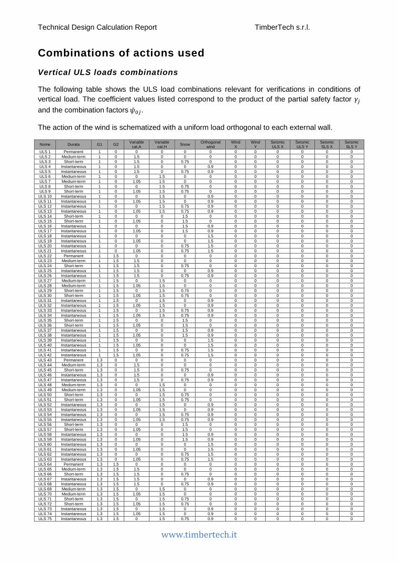
Combinations of actions used Vertical ULS loads combinations
The following table shows the ULS load combinations relevant for verifications in conditions of vertical load. The coefficient values listed correspond to the product of the partial safety factor 𝛾𝛾𝑗𝑗 and the combination factors 𝜓𝜓0𝑗𝑗.
The action of the wind is schematized with a uniform load orthogonal to each external wall.
Nome Durata G1 G2 Variable cat.A
Variable cat.H Snow Orthogonal
wind Wind
X Wind
Y Seismic ULS X
Seismic ULS Y
Seismic SLS X
Seismic SLS Y
ULS 1 Permanent 1 0 0 0 0 0 0 0 0 0 0 0 ULS 2 Medium-term 1 0 1.5 0 0 0 0 0 0 0 0 0 ULS 3 Short-term 1 0 1.5 0 0.75 0 0 0 0 0 0 0 ULS 4 Instantaneous 1 0 1.5 0 0 0.9 0 0 0 0 0 0 ULS 5 Instantaneous 1 0 1.5 0 0.75 0.9 0 0 0 0 0 0 ULS 6 Medium-term 1 0 0 1.5 0 0 0 0 0 0 0 0 ULS 7 Medium-term 1 0 1.05 1.5 0 0 0 0 0 0 0 0 ULS 8 Short-term 1 0 0 1.5 0.75 0 0 0 0 0 0 0 ULS 9 Short-term 1 0 1.05 1.5 0.75 0 0 0 0 0 0 0
ULS 10 Instantaneous 1 0 0 1.5 0 0.9 0 0 0 0 0 0 ULS 11 Instantaneous 1 0 1.05 1.5 0 0.9 0 0 0 0 0 0 ULS 12 Instantaneous 1 0 0 1.5 0.75 0.9 0 0 0 0 0 0 ULS 13 Instantaneous 1 0 1.05 1.5 0.75 0.9 0 0 0 0 0 0 ULS 14 Short-term 1 0 0 0 1.5 0 0 0 0 0 0 0 ULS 15 Short-term 1 0 1.05 0 1.5 0 0 0 0 0 0 0 ULS 16 Instantaneous 1 0 0 0 1.5 0.9 0 0 0 0 0 0 ULS 17 Instantaneous 1 0 1.05 0 1.5 0.9 0 0 0 0 0 0 ULS 18 Instantaneous 1 0 0 0 0 1.5 0 0 0 0 0 0 ULS 19 Instantaneous 1 0 1.05 0 0 1.5 0 0 0 0 0 0 ULS 20 Instantaneous 1 0 0 0 0.75 1.5 0 0 0 0 0 0 ULS 21 Instantaneous 1 0 1.05 0 0.75 1.5 0 0 0 0 0 0 ULS 22 Permanent 1 1.5 0 0 0 0 0 0 0 0 0 0 ULS 23 Medium-term 1 1.5 1.5 0 0 0 0 0 0 0 0 0 ULS 24 Short-term 1 1.5 1.5 0 0.75 0 0 0 0 0 0 0 ULS 25 Instantaneous 1 1.5 1.5 0 0 0.9 0 0 0 0 0 0 ULS 26 Instantaneous 1 1.5 1.5 0 0.75 0.9 0 0 0 0 0 0 ULS 27 Medium-term 1 1.5 0 1.5 0 0 0 0 0 0 0 0 ULS 28 Medium-term 1 1.5 1.05 1.5 0 0 0 0 0 0 0 0 ULS 29 Short-term 1 1.5 0 1.5 0.75 0 0 0 0 0 0 0 ULS 30 Short-term 1 1.5 1.05 1.5 0.75 0 0 0 0 0 0 0 ULS 31 Instantaneous 1 1.5 0 1.5 0 0.9 0 0 0 0 0 0 ULS 32 Instantaneous 1 1.5 1.05 1.5 0 0.9 0 0 0 0 0 0 ULS 33 Instantaneous 1 1.5 0 1.5 0.75 0.9 0 0 0 0 0 0 ULS 34 Instantaneous 1 1.5 1.05 1.5 0.75 0.9 0 0 0 0 0 0 ULS 35 Short-term 1 1.5 0 0 1.5 0 0 0 0 0 0 0 ULS 36 Short-term 1 1.5 1.05 0 1.5 0 0 0 0 0 0 0 ULS 37 Instantaneous 1 1.5 0 0 1.5 0.9 0 0 0 0 0 0 ULS 38 Instantaneous 1 1.5 1.05 0 1.5 0.9 0 0 0 0 0 0 ULS 39 Instantaneous 1 1.5 0 0 0 1.5 0 0 0 0 0 0 ULS 40 Instantaneous 1 1.5 1.05 0 0 1.5 0 0 0 0 0 0 ULS 41 Instantaneous 1 1.5 0 0 0.75 1.5 0 0 0 0 0 0 ULS 42 Instantaneous 1 1.5 1.05 0 0.75 1.5 0 0 0 0 0 0 ULS 43 Permanent 1.3 0 0 0 0 0 0 0 0 0 0 0 ULS 44 Medium-term 1.3 0 1.5 0 0 0 0 0 0 0 0 0 ULS 45 Short-term 1.3 0 1.5 0 0.75 0 0 0 0 0 0 0 ULS 46 Instantaneous 1.3 0 1.5 0 0 0.9 0 0 0 0 0 0 ULS 47 Instantaneous 1.3 0 1.5 0 0.75 0.9 0 0 0 0 0 0 ULS 48 Medium-term 1.3 0 0 1.5 0 0 0 0 0 0 0 0 ULS 49 Medium-term 1.3 0 1.05 1.5 0 0 0 0 0 0 0 0 ULS 50 Short-term 1.3 0 0 1.5 0.75 0 0 0 0 0 0 0 ULS 51 Short-term 1.3 0 1.05 1.5 0.75 0 0 0 0 0 0 0 ULS 52 Instantaneous 1.3 0 0 1.5 0 0.9 0 0 0 0 0 0 ULS 53 Instantaneous 1.3 0 1.05 1.5 0 0.9 0 0 0 0 0 0 ULS 54 Instantaneous 1.3 0 0 1.5 0.75 0.9 0 0 0 0 0 0 ULS 55 Instantaneous 1.3 0 1.05 1.5 0.75 0.9 0 0 0 0 0 0 ULS 56 Short-term 1.3 0 0 0 1.5 0 0 0 0 0 0 0 ULS 57 Short-term 1.3 0 1.05 0 1.5 0 0 0 0 0 0 0 ULS 58 Instantaneous 1.3 0 0 0 1.5 0.9 0 0 0 0 0 0 ULS 59 Instantaneous 1.3 0 1.05 0 1.5 0.9 0 0 0 0 0 0 ULS 60 Instantaneous 1.3 0 0 0 0 1.5 0 0 0 0 0 0 ULS 61 Instantaneous 1.3 0 1.05 0 0 1.5 0 0 0 0 0 0 ULS 62 Instantaneous 1.3 0 0 0 0.75 1.5 0 0 0 0 0 0 ULS 63 Instantaneous 1.3 0 1.05 0 0.75 1.5 0 0 0 0 0 0 ULS 64 Permanent 1.3 1.5 0 0 0 0 0 0 0 0 0 0 ULS 65 Medium-term 1.3 1.5 1.5 0 0 0 0 0 0 0 0 0 ULS 66 Short-term 1.3 1.5 1.5 0 0.75 0 0 0 0 0 0 0 ULS 67 Instantaneous 1.3 1.5 1.5 0 0 0.9 0 0 0 0 0 0 ULS 68 Instantaneous 1.3 1.5 1.5 0 0.75 0.9 0 0 0 0 0 0 ULS 69 Medium-term 1.3 1.5 0 1.5 0 0 0 0 0 0 0 0 ULS 70 Medium-term 1.3 1.5 1.05 1.5 0 0 0 0 0 0 0 0 ULS 71 Short-term 1.3 1.5 0 1.5 0.75 0 0 0 0 0 0 0 ULS 72 Short-term 1.3 1.5 1.05 1.5 0.75 0 0 0 0 0 0 0 ULS 73 Instantaneous 1.3 1.5 0 1.5 0 0.9 0 0 0 0 0 0 ULS 74 Instantaneous 1.3 1.5 1.05 1.5 0 0.9 0 0 0 0 0 0 ULS 75 Instantaneous 1.3 1.5 0 1.5 0.75 0.9 0 0 0 0 0 0
Technical Design Calculation Report TimberTech s.r.l.
www.timbertech.it
ULS 76 Instantaneous 1.3 1.5 1.05 1.5 0.75 0.9 0 0 0 0 0 0 ULS 77 Short-term 1.3 1.5 0 0 1.5 0 0 0 0 0 0 0 ULS 78 Short-term 1.3 1.5 1.05 0 1.5 0 0 0 0 0 0 0 ULS 79 Instantaneous 1.3 1.5 0 0 1.5 0.9 0 0 0 0 0 0 ULS 80 Instantaneous 1.3 1.5 1.05 0 1.5 0.9 0 0 0 0 0 0 ULS 81 Instantaneous 1.3 1.5 0 0 0 1.5 0 0 0 0 0 0 ULS 82 Instantaneous 1.3 1.5 1.05 0 0 1.5 0 0 0 0 0 0 ULS 83 Instantaneous 1.3 1.5 0 0 0.75 1.5 0 0 0 0 0 0 ULS 84 Instantaneous 1.3 1.5 1.05 0 0.75 1.5 0 0 0 0 0 0
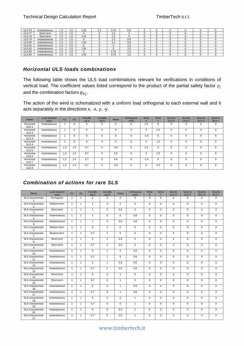
Horizontal ULS loads combinations
The following table shows the ULS load combinations relevant for verifications in conditions of vertical load. The coefficient values listed correspond to the product of the partial safety factor 𝛾𝛾𝑗𝑗 and the combination factors 𝜓𝜓0𝑗𝑗.
The action of the wind is schematized with a uniform load orthogonal to each external wall and it acts separately in the directions x, -x, y, -y.
Name Load-duration class G1 G2 Variable
cat.A Variable
cat.H Snow Orthogonal wind
Wind X
Wind Y
Seismic ULS X
Seismic ULS Y
Seismic SLS X
Seismic SLS Y
Horizontal ULS 1
Instantaneous 1 0 0 0 0 0 1.5 0 0 0 0 0
Horizontal ULS 2
Instantaneous 1 0 0 0 0 0 0 1.5 0 0 0 0
Horizontal ULS 3
Instantaneous 1 0 0 0 0 0 -1.5 0 0 0 0 0
Horizontal ULS 4
Instantaneous 1 0 0 0 0 0 0 -1.5 0 0 0 0
Horizontal ULS 5
Instantaneous 1.3 1.5 0.7 0 0.5 0 1.5 0 0 0 0 0
Horizontal ULS 6
Instantaneous 1.3 1.5 0.7 0 0.5 0 0 1.5 0 0 0 0
Horizontal ULS 7
Instantaneous 1.3 1.5 0.7 0 0.5 0 -1.5 0 0 0 0 0
Horizontal ULS 8
Instantaneous 1.3 1.5 0.7 0 0.5 0 0 -1.5 0 0 0 0
Combination of actions for rare SLS
Name Load-duration class G1 G2 Variable
cat.A Variable
cat.H Snow Orthogonal wind
Wind X
Wind Y
Seismic ULS X
Seismic ULS Y
Seismic SLS X
Seismic SLS Y
SLS characteristic 1
Permanent 1 1 0 0 0 0 0 0 0 0 0 0
SLS characteristic 2
Medium-term 1 1 1 0 0 0 0 0 0 0 0 0
SLS characteristic 3
Short-term 1 1 1 0 0.5 0 0 0 0 0 0 0
SLS characteristic 4
Instantaneous 1 1 1 0 0 0.6 0 0 0 0 0 0
SLS characteristic 5
Instantaneous 1 1 1 0 0.5 0.6 0 0 0 0 0 0
SLS characteristic 6
Medium-term 1 1 0 1 0 0 0 0 0 0 0 0
SLS characteristic 7
Medium-term 1 1 0.7 1 0 0 0 0 0 0 0 0
SLS characteristic 8
Short-term 1 1 0 1 0.5 0 0 0 0 0 0 0
SLS characteristic 9
Short-term 1 1 0.7 1 0.5 0 0 0 0 0 0 0
SLS characteristic 10
Instantaneous 1 1 0 1 0 0.6 0 0 0 0 0 0
SLS characteristic 11
Instantaneous 1 1 0.7 1 0 0.6 0 0 0 0 0 0
SLS characteristic 12
Instantaneous 1 1 0 1 0.5 0.6 0 0 0 0 0 0
SLS characteristic 13
Instantaneous 1 1 0.7 1 0.5 0.6 0 0 0 0 0 0
SLS characteristic 14
Short-term 1 1 0 0 1 0 0 0 0 0 0 0
SLS characteristic 15
Short-term 1 1 0.7 0 1 0 0 0 0 0 0 0
SLS characteristic 16
Instantaneous 1 1 0 0 1 0.6 0 0 0 0 0 0
SLS characteristic 17
Instantaneous 1 1 0.7 0 1 0.6 0 0 0 0 0 0
SLS characteristic 18
Instantaneous 1 1 0 0 0 1 0 0 0 0 0 0
SLS characteristic 19
Instantaneous 1 1 0.7 0 0 1 0 0 0 0 0 0
SLS characteristic 20
Instantaneous 1 1 0 0 0.5 1 0 0 0 0 0 0
SLS characteristic 21
Instantaneous 1 1 0.7 0 0.5 1 0 0 0 0 0 0

Technical Design Calculation Report TimberTech s.r.l.
www.timbertech.it
Technical Design Calculation Report TimberTech s.r.l.
www.timbertech.it
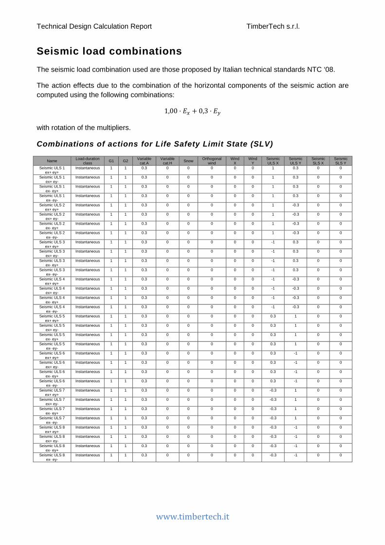
Seismic load combinations The seismic load combination used are those proposed by Italian technical standards NTC ‘08.
The action effects due to the combination of the horizontal components of the seismic action are computed using the following combinations:
1,00 ⋅ 𝐸𝐸𝑥𝑥 + 0,3 ⋅ 𝐸𝐸𝑦𝑦
with rotation of the multipliers.
Combinations of actions for Life Safety Limit State (SLV)
Name Load-duration class G1 G2 Variable
cat.A Variable
cat.H Snow Orthogonal wind
Wind X
Wind Y
Seismic ULS X
Seismic ULS Y
Seismic SLS X
Seismic SLS Y
Seismic ULS 1 ex+ ey+
Instantaneous 1 1 0.3 0 0 0 0 0 1 0.3 0 0
Seismic ULS 1 ex+ ey-
Instantaneous 1 1 0.3 0 0 0 0 0 1 0.3 0 0
Seismic ULS 1 ex- ey+
Instantaneous 1 1 0.3 0 0 0 0 0 1 0.3 0 0
Seismic ULS 1 ex- ey-
Instantaneous 1 1 0.3 0 0 0 0 0 1 0.3 0 0
Seismic ULS 2 ex+ ey+
Instantaneous 1 1 0.3 0 0 0 0 0 1 -0.3 0 0
Seismic ULS 2 ex+ ey-
Instantaneous 1 1 0.3 0 0 0 0 0 1 -0.3 0 0
Seismic ULS 2 ex- ey+
Instantaneous 1 1 0.3 0 0 0 0 0 1 -0.3 0 0
Seismic ULS 2 ex- ey-
Instantaneous 1 1 0.3 0 0 0 0 0 1 -0.3 0 0
Seismic ULS 3 ex+ ey+
Instantaneous 1 1 0.3 0 0 0 0 0 -1 0.3 0 0
Seismic ULS 3 ex+ ey-
Instantaneous 1 1 0.3 0 0 0 0 0 -1 0.3 0 0
Seismic ULS 3 ex- ey+
Instantaneous 1 1 0.3 0 0 0 0 0 -1 0.3 0 0
Seismic ULS 3 ex- ey-
Instantaneous 1 1 0.3 0 0 0 0 0 -1 0.3 0 0
Seismic ULS 4 ex+ ey+
Instantaneous 1 1 0.3 0 0 0 0 0 -1 -0.3 0 0
Seismic ULS 4 ex+ ey-
Instantaneous 1 1 0.3 0 0 0 0 0 -1 -0.3 0 0
Seismic ULS 4 ex- ey+
Instantaneous 1 1 0.3 0 0 0 0 0 -1 -0.3 0 0
Seismic ULS 4 ex- ey-
Instantaneous 1 1 0.3 0 0 0 0 0 -1 -0.3 0 0
Seismic ULS 5 ex+ ey+
Instantaneous 1 1 0.3 0 0 0 0 0 0.3 1 0 0
Seismic ULS 5 ex+ ey-
Instantaneous 1 1 0.3 0 0 0 0 0 0.3 1 0 0
Seismic ULS 5 ex- ey+
Instantaneous 1 1 0.3 0 0 0 0 0 0.3 1 0 0
Seismic ULS 5 ex- ey-
Instantaneous 1 1 0.3 0 0 0 0 0 0.3 1 0 0
Seismic ULS 6 ex+ ey+
Instantaneous 1 1 0.3 0 0 0 0 0 0.3 -1 0 0
Seismic ULS 6 ex+ ey-
Instantaneous 1 1 0.3 0 0 0 0 0 0.3 -1 0 0
Seismic ULS 6 ex- ey+
Instantaneous 1 1 0.3 0 0 0 0 0 0.3 -1 0 0
Seismic ULS 6 ex- ey-
Instantaneous 1 1 0.3 0 0 0 0 0 0.3 -1 0 0
Seismic ULS 7 ex+ ey+
Instantaneous 1 1 0.3 0 0 0 0 0 -0.3 1 0 0
Seismic ULS 7 ex+ ey-
Instantaneous 1 1 0.3 0 0 0 0 0 -0.3 1 0 0
Seismic ULS 7 ex- ey+
Instantaneous 1 1 0.3 0 0 0 0 0 -0.3 1 0 0
Seismic ULS 7 ex- ey-
Instantaneous 1 1 0.3 0 0 0 0 0 -0.3 1 0 0
Seismic ULS 8 ex+ ey+
Instantaneous 1 1 0.3 0 0 0 0 0 -0.3 -1 0 0
Seismic ULS 8 ex+ ey-
Instantaneous 1 1 0.3 0 0 0 0 0 -0.3 -1 0 0
Seismic ULS 8 ex- ey+
Instantaneous 1 1 0.3 0 0 0 0 0 -0.3 -1 0 0
Seismic ULS 8 ex- ey-
Instantaneous 1 1 0.3 0 0 0 0 0 -0.3 -1 0 0
Technical Design Calculation Report TimberTech s.r.l.
www.timbertech.it
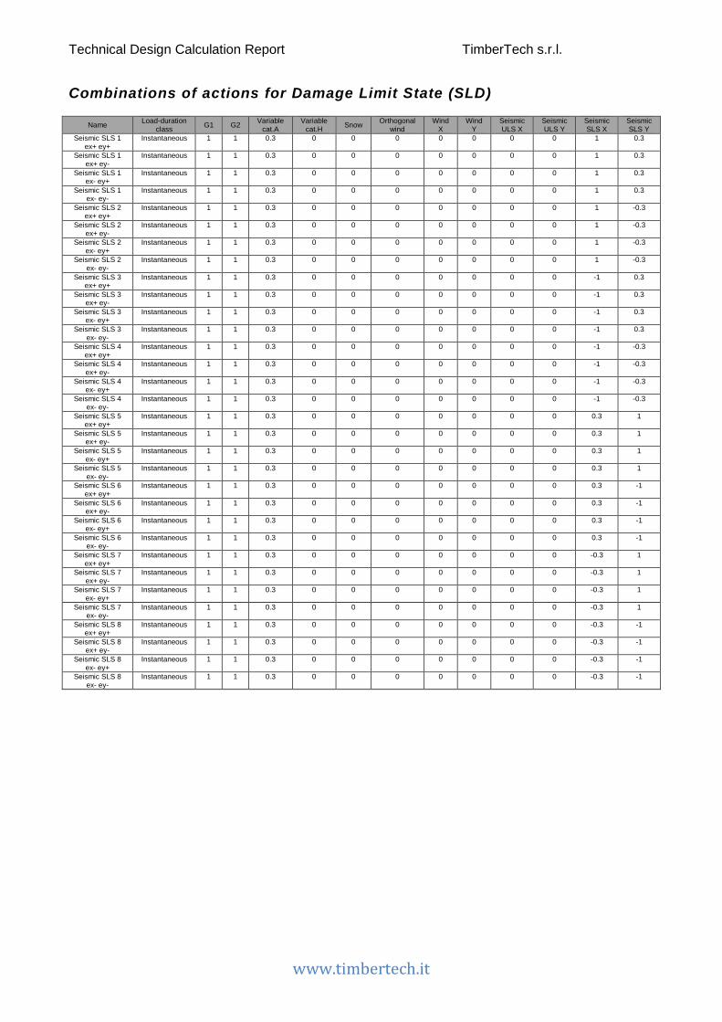
Combinations of actions for Damage Limit State (SLD)
Name Load-duration class G1 G2 Variable
cat.A Variable
cat.H Snow Orthogonal wind
Wind X
Wind Y
Seismic ULS X
Seismic ULS Y
Seismic SLS X
Seismic SLS Y
Seismic SLS 1 ex+ ey+
Instantaneous 1 1 0.3 0 0 0 0 0 0 0 1 0.3
Seismic SLS 1 ex+ ey-
Instantaneous 1 1 0.3 0 0 0 0 0 0 0 1 0.3
Seismic SLS 1 ex- ey+
Instantaneous 1 1 0.3 0 0 0 0 0 0 0 1 0.3
Seismic SLS 1 ex- ey-
Instantaneous 1 1 0.3 0 0 0 0 0 0 0 1 0.3
Seismic SLS 2 ex+ ey+
Instantaneous 1 1 0.3 0 0 0 0 0 0 0 1 -0.3
Seismic SLS 2 ex+ ey-
Instantaneous 1 1 0.3 0 0 0 0 0 0 0 1 -0.3
Seismic SLS 2 ex- ey+
Instantaneous 1 1 0.3 0 0 0 0 0 0 0 1 -0.3
Seismic SLS 2 ex- ey-
Instantaneous 1 1 0.3 0 0 0 0 0 0 0 1 -0.3
Seismic SLS 3 ex+ ey+
Instantaneous 1 1 0.3 0 0 0 0 0 0 0 -1 0.3
Seismic SLS 3 ex+ ey-
Instantaneous 1 1 0.3 0 0 0 0 0 0 0 -1 0.3
Seismic SLS 3 ex- ey+
Instantaneous 1 1 0.3 0 0 0 0 0 0 0 -1 0.3
Seismic SLS 3 ex- ey-
Instantaneous 1 1 0.3 0 0 0 0 0 0 0 -1 0.3
Seismic SLS 4 ex+ ey+
Instantaneous 1 1 0.3 0 0 0 0 0 0 0 -1 -0.3
Seismic SLS 4 ex+ ey-
Instantaneous 1 1 0.3 0 0 0 0 0 0 0 -1 -0.3
Seismic SLS 4 ex- ey+
Instantaneous 1 1 0.3 0 0 0 0 0 0 0 -1 -0.3
Seismic SLS 4 ex- ey-
Instantaneous 1 1 0.3 0 0 0 0 0 0 0 -1 -0.3
Seismic SLS 5 ex+ ey+
Instantaneous 1 1 0.3 0 0 0 0 0 0 0 0.3 1
Seismic SLS 5 ex+ ey-
Instantaneous 1 1 0.3 0 0 0 0 0 0 0 0.3 1
Seismic SLS 5 ex- ey+
Instantaneous 1 1 0.3 0 0 0 0 0 0 0 0.3 1
Seismic SLS 5 ex- ey-
Instantaneous 1 1 0.3 0 0 0 0 0 0 0 0.3 1
Seismic SLS 6 ex+ ey+
Instantaneous 1 1 0.3 0 0 0 0 0 0 0 0.3 -1
Seismic SLS 6 ex+ ey-
Instantaneous 1 1 0.3 0 0 0 0 0 0 0 0.3 -1
Seismic SLS 6 ex- ey+
Instantaneous 1 1 0.3 0 0 0 0 0 0 0 0.3 -1
Seismic SLS 6 ex- ey-
Instantaneous 1 1 0.3 0 0 0 0 0 0 0 0.3 -1
Seismic SLS 7 ex+ ey+
Instantaneous 1 1 0.3 0 0 0 0 0 0 0 -0.3 1
Seismic SLS 7 ex+ ey-
Instantaneous 1 1 0.3 0 0 0 0 0 0 0 -0.3 1
Seismic SLS 7 ex- ey+
Instantaneous 1 1 0.3 0 0 0 0 0 0 0 -0.3 1
Seismic SLS 7 ex- ey-
Instantaneous 1 1 0.3 0 0 0 0 0 0 0 -0.3 1
Seismic SLS 8 ex+ ey+
Instantaneous 1 1 0.3 0 0 0 0 0 0 0 -0.3 -1
Seismic SLS 8 ex+ ey-
Instantaneous 1 1 0.3 0 0 0 0 0 0 0 -0.3 -1
Seismic SLS 8 ex- ey+
Instantaneous 1 1 0.3 0 0 0 0 0 0 0 -0.3 -1
Seismic SLS 8 ex- ey-
Instantaneous 1 1 0.3 0 0 0 0 0 0 0 -0.3 -1

Technical Design Calculation Report TimberTech s.r.l.
www.timbertech.it
Horizontal actions
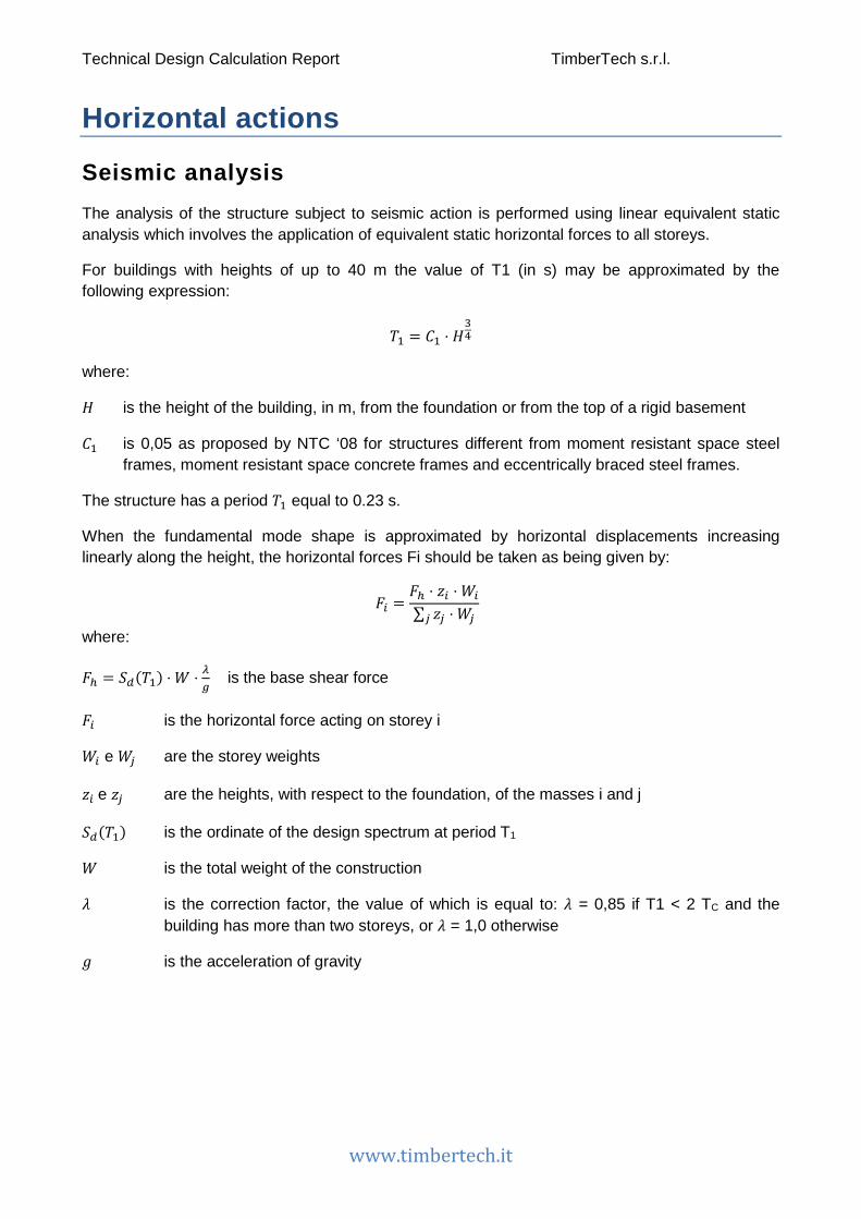
Seismic analysis The analysis of the structure subject to seismic action is performed using linear equivalent static analysis which involves the application of equivalent static horizontal forces to all storeys.
For buildings with heights of up to 40 m the value of T1 (in s) may be approximated by the following expression:
𝑇𝑇1 = 𝐶𝐶1 ⋅ 𝐻𝐻34
where:
𝐻𝐻 is the height of the building, in m, from the foundation or from the top of a rigid basement
𝐶𝐶1 is 0,05 as proposed by NTC ‘08 for structures different from moment resistant space steel frames, moment resistant space concrete frames and eccentrically braced steel frames.
The structure has a period 𝑇𝑇1 equal to 0.23 s.
When the fundamental mode shape is approximated by horizontal displacements increasing linearly along the height, the horizontal forces Fi should be taken as being given by:
𝐹𝐹𝑖𝑖 =𝐹𝐹ℎ ⋅ 𝑧𝑧𝑖𝑖 ⋅ 𝑊𝑊𝑖𝑖∑ 𝑧𝑧𝑗𝑗 ⋅ 𝑊𝑊𝑗𝑗𝑗𝑗
where:
𝐹𝐹ℎ = 𝑆𝑆𝑑𝑑(𝑇𝑇1) ⋅ 𝑊𝑊 ⋅ 𝜆𝜆𝑔𝑔 is the base shear force
𝐹𝐹𝑖𝑖 is the horizontal force acting on storey i
𝑊𝑊𝑖𝑖 e 𝑊𝑊𝑗𝑗 are the storey weights
𝑧𝑧𝑖𝑖 e 𝑧𝑧𝑗𝑗 are the heights, with respect to the foundation, of the masses i and j
𝑆𝑆𝑑𝑑(𝑇𝑇1) is the ordinate of the design spectrum at period T1
𝑊𝑊 is the total weight of the construction
𝜆𝜆 is the correction factor, the value of which is equal to: 𝜆𝜆 = 0,85 if T1 < 2 TC and the building has more than two storeys, or 𝜆𝜆 = 1,0 otherwise
𝑔𝑔 is the acceleration of gravity

Technical Design Calculation Report TimberTech s.r.l.
www.timbertech.it
The inertial effects of the design seismic action shall be evaluated by taking into account the presence of the masses associated with all gravity loads appearing in the following combination of actions:
G1 + G2 + �ψ2jj
⋅ Qkj
The base shear forces for SLD and SLV and the respective acceleration values are given below.
Ordinate of the design spectrum SLV Sd (T1): 0.12 g
Total base shear force Fh SLV: 156.35 kN
Ordinate of the spectrum SLD Sd (T1): 0.11 g
Total base shear force Fh SLD: 137.05 kN
The table below illustrates the horizontal forces acting on the storeys due to the seismic action and the coordinates of their respective application points.
Storey Height above foundation zi
[m] xG [m]
yG [m]
Mass i [kg]
Fi,SLV [kN]
Fi,SLD [kN]
1 3.2 7.71 3.75 68621 51.91 45.50
2 7.15 7.62 3.62 61793 104.44 91.55
Wind The table below illustrates the horizontal forces acting on the storeys due to the wind action and the coordinates of their respective application points.
Storey Height above foundation [m]
xG,wind [m]
yG,wind [m]
Fx [kN]
Fy [kN]
1 3.2 7.76 2.78 27.83 38.45 2 7.15 7.65 2.76 15.63 20.92

Technical Design Calculation Report TimberTech s.r.l.
www.timbertech.it
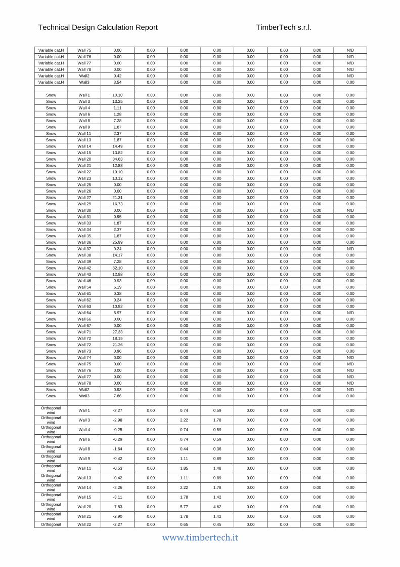
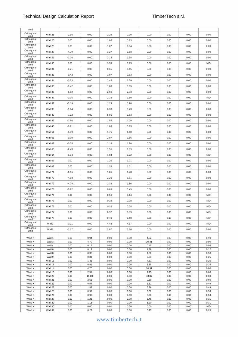
The action effects In this chapter are reported the internal stresses present in the structural elements and their connections caused by the different loads.
Walls
Wall name: Wall ID
N: Total axial force
V2: Shear force (in-plane)
V3: Shear force (out-of-plane)
M2-2: Bending moment (out-of-plane)
M3-3: Bending moment (in-plane)
Va: Shear force on the single connection
Ta: Tensile force on the single anchor
dr: Interstory drift
Load Wall name N [kN]
V2 [kN]
V3 [kN]
M2-2 [kNm]
M3-3 [kNm]
Va [kN]
Ta [kN]
dr [mm]
G1 Wall 1 10.41 0.00 0.00 0.00 0.00 0.00 0.00 0.00 G1 Wall 3 22.99 0.00 0.00 0.00 0.00 0.00 0.00 0.00 G1 Wall 4 8.33 0.00 0.00 0.00 0.00 0.00 0.00 0.00 G1 Wall 6 11.94 0.00 0.00 0.00 0.00 0.00 0.00 0.00 G1 Wall 8 5.32 0.00 0.00 0.00 0.00 0.00 0.00 0.00 G1 Wall 9 7.09 0.00 0.00 0.00 0.00 0.00 0.00 0.00 G1 Wall 11 13.49 0.00 0.00 0.00 0.00 0.00 0.00 0.00 G1 Wall 13 7.09 0.00 0.00 0.00 0.00 0.00 0.00 0.00 G1 Wall 14 27.74 0.00 0.00 0.00 0.00 0.00 0.00 0.00 G1 Wall 15 19.64 0.00 0.00 0.00 0.00 0.00 0.00 0.00 G1 Wall 20 59.43 0.00 0.00 0.00 0.00 0.00 0.00 0.00 G1 Wall 21 18.04 0.00 0.00 0.00 0.00 0.00 0.00 0.00 G1 Wall 22 5.95 0.00 0.00 0.00 0.00 0.00 0.00 0.00 G1 Wall 23 9.46 0.00 0.00 0.00 0.00 0.00 0.00 0.00 G1 Wall 25 3.08 0.00 0.00 0.00 0.00 0.00 0.00 0.00 G1 Wall 26 3.08 0.00 0.00 0.00 0.00 0.00 0.00 0.00 G1 Wall 27 18.25 0.00 0.00 0.00 0.00 0.00 0.00 0.00 G1 Wall 29 16.11 0.00 0.00 0.00 0.00 0.00 0.00 0.00 G1 Wall 30 9.09 0.00 0.00 0.00 0.00 0.00 0.00 N/D G1 Wall 31 3.82 0.00 0.00 0.00 0.00 0.00 0.00 0.00 G1 Wall 33 3.58 0.00 0.00 0.00 0.00 0.00 0.00 0.00 G1 Wall 34 7.45 0.00 0.00 0.00 0.00 0.00 0.00 0.00 G1 Wall 35 3.59 0.00 0.00 0.00 0.00 0.00 0.00 0.00 G1 Wall 36 18.78 0.00 0.00 0.00 0.00 0.00 0.00 0.00 G1 Wall 37 6.11 0.00 0.00 0.00 0.00 0.00 0.00 N/D G1 Wall 38 9.96 0.00 0.00 0.00 0.00 0.00 0.00 0.00 G1 Wall 39 3.94 0.00 0.00 0.00 0.00 0.00 0.00 0.00 G1 Wall 42 26.68 0.00 0.00 0.00 0.00 0.00 0.00 0.00 G1 Wall 43 9.48 0.00 0.00 0.00 0.00 0.00 0.00 0.00 G1 Wall 46 3.19 0.00 0.00 0.00 0.00 0.00 0.00 0.00 G1 Wall 54 17.94 0.00 0.00 0.00 0.00 0.00 0.00 0.00 G1 Wall 61 14.07 0.00 0.00 0.00 0.00 0.00 0.00 0.00 G1 Wall 62 6.11 0.00 0.00 0.00 0.00 0.00 0.00 0.00 G1 Wall 63 8.61 0.00 0.00 0.00 0.00 0.00 0.00 0.00 G1 Wall 64 5.21 0.00 0.00 0.00 0.00 0.00 0.00 N/D G1 Wall 66 7.82 0.00 0.00 0.00 0.00 0.00 0.00 0.00 G1 Wall 67 7.82 0.00 0.00 0.00 0.00 0.00 0.00 0.00 G1 Wall 71 48.36 0.00 0.00 0.00 0.00 0.00 0.00 0.00 G1 Wall 72 43.38 0.00 0.00 0.00 0.00 0.00 0.00 0.00
Technical Design Calculation Report TimberTech s.r.l.
www.timbertech.it
G1 Wall 72 38.88 0.00 0.00 0.00 0.00 0.00 0.00 0.00 G1 Wall 73 3.82 0.00 0.00 0.00 0.00 0.00 0.00 0.00 G1 Wall 74 1.45 0.00 0.00 0.00 0.00 0.00 0.00 N/D G1 Wall 75 0.84 0.00 0.00 0.00 0.00 0.00 0.00 N/D G1 Wall 76 0.84 0.00 0.00 0.00 0.00 0.00 0.00 N/D G1 Wall 77 0.96 0.00 0.00 0.00 0.00 0.00 0.00 N/D G1 Wall 78 1.04 0.00 0.00 0.00 0.00 0.00 0.00 N/D G1 Wall2 11.88 0.00 0.00 0.00 0.00 0.00 0.00 N/D G1 Wall3 23.62 0.00 0.00 0.00 0.00 0.00 0.00 0.00
G2 Wall 1 27.68 0.00 0.00 0.00 0.00 0.00 0.00 0.00 G2 Wall 3 51.69 0.00 0.00 0.00 0.00 0.00 0.00 0.00 G2 Wall 4 15.69 0.00 0.00 0.00 0.00 0.00 0.00 0.00 G2 Wall 6 20.63 0.00 0.00 0.00 0.00 0.00 0.00 0.00 G2 Wall 8 15.13 0.00 0.00 0.00 0.00 0.00 0.00 0.00 G2 Wall 9 9.46 0.00 0.00 0.00 0.00 0.00 0.00 0.00 G2 Wall 11 16.28 0.00 0.00 0.00 0.00 0.00 0.00 0.00 G2 Wall 13 9.46 0.00 0.00 0.00 0.00 0.00 0.00 0.00 G2 Wall 14 59.46 0.00 0.00 0.00 0.00 0.00 0.00 0.00 G2 Wall 15 45.11 0.00 0.00 0.00 0.00 0.00 0.00 0.00 G2 Wall 20 124.85 0.00 0.00 0.00 0.00 0.00 0.00 0.00 G2 Wall 21 38.80 0.00 0.00 0.00 0.00 0.00 0.00 0.00 G2 Wall 22 19.87 0.00 0.00 0.00 0.00 0.00 0.00 0.00 G2 Wall 23 28.03 0.00 0.00 0.00 0.00 0.00 0.00 0.00 G2 Wall 25 3.82 0.00 0.00 0.00 0.00 0.00 0.00 0.00 G2 Wall 26 3.83 0.00 0.00 0.00 0.00 0.00 0.00 0.00 G2 Wall 27 46.89 0.00 0.00 0.00 0.00 0.00 0.00 0.00 G2 Wall 29 38.40 0.00 0.00 0.00 0.00 0.00 0.00 0.00 G2 Wall 30 9.09 0.00 0.00 0.00 0.00 0.00 0.00 N/D G2 Wall 31 8.19 0.00 0.00 0.00 0.00 0.00 0.00 0.00 G2 Wall 33 6.16 0.00 0.00 0.00 0.00 0.00 0.00 0.00 G2 Wall 34 10.64 0.00 0.00 0.00 0.00 0.00 0.00 0.00 G2 Wall 35 6.16 0.00 0.00 0.00 0.00 0.00 0.00 0.00 G2 Wall 36 53.38 0.00 0.00 0.00 0.00 0.00 0.00 0.00 G2 Wall 37 6.41 0.00 0.00 0.00 0.00 0.00 0.00 N/D G2 Wall 38 30.11 0.00 0.00 0.00 0.00 0.00 0.00 0.00 G2 Wall 39 13.98 0.00 0.00 0.00 0.00 0.00 0.00 0.00 G2 Wall 42 70.92 0.00 0.00 0.00 0.00 0.00 0.00 0.00 G2 Wall 43 27.22 0.00 0.00 0.00 0.00 0.00 0.00 0.00 G2 Wall 46 4.48 0.00 0.00 0.00 0.00 0.00 0.00 0.00 G2 Wall 54 31.06 0.00 0.00 0.00 0.00 0.00 0.00 0.00 G2 Wall 61 17.35 0.00 0.00 0.00 0.00 0.00 0.00 0.00 G2 Wall 62 6.41 0.00 0.00 0.00 0.00 0.00 0.00 0.00 G2 Wall 63 23.53 0.00 0.00 0.00 0.00 0.00 0.00 0.00 G2 Wall 64 13.44 0.00 0.00 0.00 0.00 0.00 0.00 N/D G2 Wall 66 10.65 0.00 0.00 0.00 0.00 0.00 0.00 0.00 G2 Wall 67 10.65 0.00 0.00 0.00 0.00 0.00 0.00 0.00 G2 Wall 71 110.55 0.00 0.00 0.00 0.00 0.00 0.00 0.00 G2 Wall 72 94.01 0.00 0.00 0.00 0.00 0.00 0.00 0.00 G2 Wall 72 93.94 0.00 0.00 0.00 0.00 0.00 0.00 0.00 G2 Wall 73 8.19 0.00 0.00 0.00 0.00 0.00 0.00 0.00 G2 Wall 74 1.45 0.00 0.00 0.00 0.00 0.00 0.00 N/D G2 Wall 75 0.84 0.00 0.00 0.00 0.00 0.00 0.00 N/D G2 Wall 76 0.84 0.00 0.00 0.00 0.00 0.00 0.00 N/D G2 Wall 77 0.96 0.00 0.00 0.00 0.00 0.00 0.00 N/D G2 Wall 78 1.04 0.00 0.00 0.00 0.00 0.00 0.00 N/D G2 Wall2 13.17 0.00 0.00 0.00 0.00 0.00 0.00 N/D G2 Wall3 39.54 0.00 0.00 0.00 0.00 0.00 0.00 0.00
Variable cat.A Wall 1 5.47 0.00 0.00 0.00 0.00 0.00 0.00 0.00 Variable cat.A Wall 3 17.79 0.00 0.00 0.00 0.00 0.00 0.00 0.00 Variable cat.A Wall 4 10.19 0.00 0.00 0.00 0.00 0.00 0.00 0.00 Variable cat.A Wall 6 13.04 0.00 0.00 0.00 0.00 0.00 0.00 0.00 Variable cat.A Wall 8 0.00 0.00 0.00 0.00 0.00 0.00 0.00 0.00 Variable cat.A Wall 9 0.00 0.00 0.00 0.00 0.00 0.00 0.00 0.00 Variable cat.A Wall 11 0.00 0.00 0.00 0.00 0.00 0.00 0.00 0.00 Variable cat.A Wall 13 0.00 0.00 0.00 0.00 0.00 0.00 0.00 0.00 Variable cat.A Wall 14 22.57 0.00 0.00 0.00 0.00 0.00 0.00 0.00 Variable cat.A Wall 15 10.24 0.00 0.00 0.00 0.00 0.00 0.00 0.00 Variable cat.A Wall 20 28.58 0.00 0.00 0.00 0.00 0.00 0.00 0.00 Variable cat.A Wall 21 6.49 0.00 0.00 0.00 0.00 0.00 0.00 0.00 Variable cat.A Wall 22 0.00 0.00 0.00 0.00 0.00 0.00 0.00 0.00 Variable cat.A Wall 23 1.05 0.00 0.00 0.00 0.00 0.00 0.00 0.00 Variable cat.A Wall 25 1.06 0.00 0.00 0.00 0.00 0.00 0.00 0.00 Variable cat.A Wall 26 1.06 0.00 0.00 0.00 0.00 0.00 0.00 0.00

Technical Design Calculation Report TimberTech s.r.l.
www.timbertech.it
Variable cat.A Wall 27 0.00 0.00 0.00 0.00 0.00 0.00 0.00 0.00 Variable cat.A Wall 29 0.00 0.00 0.00 0.00 0.00 0.00 0.00 0.00 Variable cat.A Wall 30 0.00 0.00 0.00 0.00 0.00 0.00 0.00 N/D Variable cat.A Wall 31 4.79 0.00 0.00 0.00 0.00 0.00 0.00 0.00 Variable cat.A Wall 33 0.00 0.00 0.00 0.00 0.00 0.00 0.00 0.00 Variable cat.A Wall 34 0.00 0.00 0.00 0.00 0.00 0.00 0.00 0.00 Variable cat.A Wall 35 0.00 0.00 0.00 0.00 0.00 0.00 0.00 0.00 Variable cat.A Wall 36 0.00 0.00 0.00 0.00 0.00 0.00 0.00 0.00 Variable cat.A Wall 37 0.31 0.00 0.00 0.00 0.00 0.00 0.00 N/D Variable cat.A Wall 38 1.25 0.00 0.00 0.00 0.00 0.00 0.00 0.00 Variable cat.A Wall 39 0.00 0.00 0.00 0.00 0.00 0.00 0.00 0.00 Variable cat.A Wall 42 0.00 0.00 0.00 0.00 0.00 0.00 0.00 0.00 Variable cat.A Wall 43 0.00 0.00 0.00 0.00 0.00 0.00 0.00 0.00 Variable cat.A Wall 46 0.00 0.00 0.00 0.00 0.00 0.00 0.00 0.00 Variable cat.A Wall 54 9.47 0.00 0.00 0.00 0.00 0.00 0.00 0.00 Variable cat.A Wall 61 5.71 0.00 0.00 0.00 0.00 0.00 0.00 0.00 Variable cat.A Wall 62 0.31 0.00 0.00 0.00 0.00 0.00 0.00 0.00 Variable cat.A Wall 63 0.00 0.00 0.00 0.00 0.00 0.00 0.00 0.00 Variable cat.A Wall 64 0.00 0.00 0.00 0.00 0.00 0.00 0.00 N/D Variable cat.A Wall 66 4.62 0.00 0.00 0.00 0.00 0.00 0.00 0.00 Variable cat.A Wall 67 4.62 0.00 0.00 0.00 0.00 0.00 0.00 0.00 Variable cat.A Wall 71 44.75 0.00 0.00 0.00 0.00 0.00 0.00 0.00 Variable cat.A Wall 72 44.16 0.00 0.00 0.00 0.00 0.00 0.00 0.00 Variable cat.A Wall 72 41.12 0.00 0.00 0.00 0.00 0.00 0.00 0.00 Variable cat.A Wall 73 4.79 0.00 0.00 0.00 0.00 0.00 0.00 0.00 Variable cat.A Wall 74 0.00 0.00 0.00 0.00 0.00 0.00 0.00 N/D Variable cat.A Wall 75 0.00 0.00 0.00 0.00 0.00 0.00 0.00 N/D Variable cat.A Wall 76 0.00 0.00 0.00 0.00 0.00 0.00 0.00 N/D Variable cat.A Wall 77 0.00 0.00 0.00 0.00 0.00 0.00 0.00 N/D Variable cat.A Wall 78 0.00 0.00 0.00 0.00 0.00 0.00 0.00 N/D Variable cat.A Wall2 0.00 0.00 0.00 0.00 0.00 0.00 0.00 N/D Variable cat.A Wall3 10.59 0.00 0.00 0.00 0.00 0.00 0.00 0.00
Variable cat.H Wall 1 4.55 0.00 0.00 0.00 0.00 0.00 0.00 0.00 Variable cat.H Wall 3 5.97 0.00 0.00 0.00 0.00 0.00 0.00 0.00 Variable cat.H Wall 4 0.50 0.00 0.00 0.00 0.00 0.00 0.00 0.00 Variable cat.H Wall 6 0.58 0.00 0.00 0.00 0.00 0.00 0.00 0.00 Variable cat.H Wall 8 3.28 0.00 0.00 0.00 0.00 0.00 0.00 0.00 Variable cat.H Wall 9 0.84 0.00 0.00 0.00 0.00 0.00 0.00 0.00 Variable cat.H Wall 11 1.07 0.00 0.00 0.00 0.00 0.00 0.00 0.00 Variable cat.H Wall 13 0.84 0.00 0.00 0.00 0.00 0.00 0.00 0.00 Variable cat.H Wall 14 6.53 0.00 0.00 0.00 0.00 0.00 0.00 0.00 Variable cat.H Wall 15 6.22 0.00 0.00 0.00 0.00 0.00 0.00 0.00 Variable cat.H Wall 20 15.68 0.00 0.00 0.00 0.00 0.00 0.00 0.00 Variable cat.H Wall 21 5.80 0.00 0.00 0.00 0.00 0.00 0.00 0.00 Variable cat.H Wall 22 4.55 0.00 0.00 0.00 0.00 0.00 0.00 0.00 Variable cat.H Wall 23 5.91 0.00 0.00 0.00 0.00 0.00 0.00 0.00 Variable cat.H Wall 25 0.00 0.00 0.00 0.00 0.00 0.00 0.00 0.00 Variable cat.H Wall 26 0.00 0.00 0.00 0.00 0.00 0.00 0.00 0.00 Variable cat.H Wall 27 9.60 0.00 0.00 0.00 0.00 0.00 0.00 0.00 Variable cat.H Wall 29 7.53 0.00 0.00 0.00 0.00 0.00 0.00 0.00 Variable cat.H Wall 30 0.00 0.00 0.00 0.00 0.00 0.00 0.00 N/D Variable cat.H Wall 31 0.43 0.00 0.00 0.00 0.00 0.00 0.00 0.00 Variable cat.H Wall 33 0.84 0.00 0.00 0.00 0.00 0.00 0.00 0.00 Variable cat.H Wall 34 1.07 0.00 0.00 0.00 0.00 0.00 0.00 0.00 Variable cat.H Wall 35 0.84 0.00 0.00 0.00 0.00 0.00 0.00 0.00 Variable cat.H Wall 36 11.66 0.00 0.00 0.00 0.00 0.00 0.00 0.00 Variable cat.H Wall 37 0.11 0.00 0.00 0.00 0.00 0.00 0.00 N/D Variable cat.H Wall 38 6.38 0.00 0.00 0.00 0.00 0.00 0.00 0.00 Variable cat.H Wall 39 3.28 0.00 0.00 0.00 0.00 0.00 0.00 0.00 Variable cat.H Wall 42 14.45 0.00 0.00 0.00 0.00 0.00 0.00 0.00 Variable cat.H Wall 43 5.80 0.00 0.00 0.00 0.00 0.00 0.00 0.00 Variable cat.H Wall 46 0.42 0.00 0.00 0.00 0.00 0.00 0.00 0.00 Variable cat.H Wall 54 2.79 0.00 0.00 0.00 0.00 0.00 0.00 0.00 Variable cat.H Wall 61 0.17 0.00 0.00 0.00 0.00 0.00 0.00 0.00 Variable cat.H Wall 62 0.11 0.00 0.00 0.00 0.00 0.00 0.00 0.00 Variable cat.H Wall 63 4.87 0.00 0.00 0.00 0.00 0.00 0.00 0.00 Variable cat.H Wall 64 2.69 0.00 0.00 0.00 0.00 0.00 0.00 N/D Variable cat.H Wall 66 0.00 0.00 0.00 0.00 0.00 0.00 0.00 0.00 Variable cat.H Wall 67 0.00 0.00 0.00 0.00 0.00 0.00 0.00 0.00 Variable cat.H Wall 71 12.30 0.00 0.00 0.00 0.00 0.00 0.00 0.00 Variable cat.H Wall 72 8.17 0.00 0.00 0.00 0.00 0.00 0.00 0.00 Variable cat.H Wall 72 9.57 0.00 0.00 0.00 0.00 0.00 0.00 0.00 Variable cat.H Wall 73 0.43 0.00 0.00 0.00 0.00 0.00 0.00 0.00 Variable cat.H Wall 74 0.00 0.00 0.00 0.00 0.00 0.00 0.00 N/D
Technical Design Calculation Report TimberTech s.r.l.
www.timbertech.it
Variable cat.H Wall 75 0.00 0.00 0.00 0.00 0.00 0.00 0.00 N/D Variable cat.H Wall 76 0.00 0.00 0.00 0.00 0.00 0.00 0.00 N/D Variable cat.H Wall 77 0.00 0.00 0.00 0.00 0.00 0.00 0.00 N/D Variable cat.H Wall 78 0.00 0.00 0.00 0.00 0.00 0.00 0.00 N/D Variable cat.H Wall2 0.42 0.00 0.00 0.00 0.00 0.00 0.00 N/D Variable cat.H Wall3 3.54 0.00 0.00 0.00 0.00 0.00 0.00 0.00
Snow Wall 1 10.10 0.00 0.00 0.00 0.00 0.00 0.00 0.00 Snow Wall 3 13.25 0.00 0.00 0.00 0.00 0.00 0.00 0.00 Snow Wall 4 1.11 0.00 0.00 0.00 0.00 0.00 0.00 0.00 Snow Wall 6 1.28 0.00 0.00 0.00 0.00 0.00 0.00 0.00 Snow Wall 8 7.28 0.00 0.00 0.00 0.00 0.00 0.00 0.00 Snow Wall 9 1.87 0.00 0.00 0.00 0.00 0.00 0.00 0.00 Snow Wall 11 2.37 0.00 0.00 0.00 0.00 0.00 0.00 0.00 Snow Wall 13 1.87 0.00 0.00 0.00 0.00 0.00 0.00 0.00 Snow Wall 14 14.49 0.00 0.00 0.00 0.00 0.00 0.00 0.00 Snow Wall 15 13.82 0.00 0.00 0.00 0.00 0.00 0.00 0.00 Snow Wall 20 34.83 0.00 0.00 0.00 0.00 0.00 0.00 0.00 Snow Wall 21 12.88 0.00 0.00 0.00 0.00 0.00 0.00 0.00 Snow Wall 22 10.10 0.00 0.00 0.00 0.00 0.00 0.00 0.00 Snow Wall 23 13.12 0.00 0.00 0.00 0.00 0.00 0.00 0.00 Snow Wall 25 0.00 0.00 0.00 0.00 0.00 0.00 0.00 0.00 Snow Wall 26 0.00 0.00 0.00 0.00 0.00 0.00 0.00 0.00 Snow Wall 27 21.31 0.00 0.00 0.00 0.00 0.00 0.00 0.00 Snow Wall 29 16.73 0.00 0.00 0.00 0.00 0.00 0.00 0.00 Snow Wall 30 0.00 0.00 0.00 0.00 0.00 0.00 0.00 N/D Snow Wall 31 0.95 0.00 0.00 0.00 0.00 0.00 0.00 0.00 Snow Wall 33 1.87 0.00 0.00 0.00 0.00 0.00 0.00 0.00 Snow Wall 34 2.37 0.00 0.00 0.00 0.00 0.00 0.00 0.00 Snow Wall 35 1.87 0.00 0.00 0.00 0.00 0.00 0.00 0.00 Snow Wall 36 25.89 0.00 0.00 0.00 0.00 0.00 0.00 0.00 Snow Wall 37 0.24 0.00 0.00 0.00 0.00 0.00 0.00 N/D Snow Wall 38 14.17 0.00 0.00 0.00 0.00 0.00 0.00 0.00 Snow Wall 39 7.28 0.00 0.00 0.00 0.00 0.00 0.00 0.00 Snow Wall 42 32.10 0.00 0.00 0.00 0.00 0.00 0.00 0.00 Snow Wall 43 12.88 0.00 0.00 0.00 0.00 0.00 0.00 0.00 Snow Wall 46 0.93 0.00 0.00 0.00 0.00 0.00 0.00 0.00 Snow Wall 54 6.19 0.00 0.00 0.00 0.00 0.00 0.00 0.00 Snow Wall 61 0.38 0.00 0.00 0.00 0.00 0.00 0.00 0.00 Snow Wall 62 0.24 0.00 0.00 0.00 0.00 0.00 0.00 0.00 Snow Wall 63 10.82 0.00 0.00 0.00 0.00 0.00 0.00 0.00 Snow Wall 64 5.97 0.00 0.00 0.00 0.00 0.00 0.00 N/D Snow Wall 66 0.00 0.00 0.00 0.00 0.00 0.00 0.00 0.00 Snow Wall 67 0.00 0.00 0.00 0.00 0.00 0.00 0.00 0.00 Snow Wall 71 27.33 0.00 0.00 0.00 0.00 0.00 0.00 0.00 Snow Wall 72 18.15 0.00 0.00 0.00 0.00 0.00 0.00 0.00 Snow Wall 72 21.26 0.00 0.00 0.00 0.00 0.00 0.00 0.00 Snow Wall 73 0.96 0.00 0.00 0.00 0.00 0.00 0.00 0.00 Snow Wall 74 0.00 0.00 0.00 0.00 0.00 0.00 0.00 N/D Snow Wall 75 0.00 0.00 0.00 0.00 0.00 0.00 0.00 N/D Snow Wall 76 0.00 0.00 0.00 0.00 0.00 0.00 0.00 N/D Snow Wall 77 0.00 0.00 0.00 0.00 0.00 0.00 0.00 N/D Snow Wall 78 0.00 0.00 0.00 0.00 0.00 0.00 0.00 N/D Snow Wall2 0.93 0.00 0.00 0.00 0.00 0.00 0.00 N/D Snow Wall3 7.86 0.00 0.00 0.00 0.00 0.00 0.00 0.00
Orthogonal
wind Wall 1 -2.27 0.00 0.74 0.59 0.00 0.00 0.00 0.00
Orthogonal wind Wall 3 -2.98 0.00 2.22 1.78 0.00 0.00 0.00 0.00
Orthogonal wind Wall 4 -0.25 0.00 0.74 0.59 0.00 0.00 0.00 0.00
Orthogonal wind Wall 6 -0.29 0.00 0.74 0.59 0.00 0.00 0.00 0.00
Orthogonal wind Wall 8 -1.64 0.00 0.44 0.36 0.00 0.00 0.00 0.00
Orthogonal wind Wall 9 -0.42 0.00 1.11 0.89 0.00 0.00 0.00 0.00
Orthogonal wind Wall 11 -0.53 0.00 1.85 1.48 0.00 0.00 0.00 0.00
Orthogonal wind Wall 13 -0.42 0.00 1.11 0.89 0.00 0.00 0.00 0.00
Orthogonal wind Wall 14 -3.26 0.00 2.22 1.78 0.00 0.00 0.00 0.00
Orthogonal wind Wall 15 -3.11 0.00 1.78 1.42 0.00 0.00 0.00 0.00
Orthogonal wind Wall 20 -7.83 0.00 5.77 4.62 0.00 0.00 0.00 0.00
Orthogonal wind Wall 21 -2.90 0.00 1.78 1.42 0.00 0.00 0.00 0.00
Orthogonal Wall 22 -2.27 0.00 0.65 0.45 0.00 0.00 0.00 0.00
Technical Design Calculation Report TimberTech s.r.l.
www.timbertech.it
wind Orthogonal
wind Wall 23 -2.95 0.00 1.29 0.90 0.00 0.00 0.00 0.00
Orthogonal wind Wall 25 0.00 0.00 1.06 0.83 0.00 0.00 0.00 0.00
Orthogonal wind Wall 26 0.00 0.00 1.07 0.84 0.00 0.00 0.00 0.00
Orthogonal wind Wall 27 -4.79 0.00 3.27 3.68 0.00 0.00 0.00 0.00
Orthogonal wind Wall 29 -3.76 0.00 3.18 3.58 0.00 0.00 0.00 0.00
Orthogonal wind Wall 30 0.00 0.00 3.53 3.25 0.00 0.00 0.00 N/D
Orthogonal wind Wall 31 -0.21 0.00 0.65 0.45 0.00 0.00 0.00 0.00
Orthogonal wind Wall 33 -0.42 0.00 1.07 0.83 0.00 0.00 0.00 0.00
Orthogonal wind Wall 34 -0.53 0.00 2.45 2.59 0.00 0.00 0.00 0.00
Orthogonal wind Wall 35 -0.42 0.00 1.08 0.85 0.00 0.00 0.00 0.00
Orthogonal wind Wall 36 -5.82 0.00 2.60 2.93 0.00 0.00 0.00 0.00
Orthogonal wind Wall 37 -0.05 0.00 2.16 1.80 0.00 0.00 0.00 N/D
Orthogonal wind Wall 38 -3.19 0.00 1.29 0.90 0.00 0.00 0.00 0.00
Orthogonal wind Wall 39 -1.64 0.00 0.33 0.23 0.00 0.00 0.00 0.00
Orthogonal wind Wall 42 -7.22 0.00 5.05 3.53 0.00 0.00 0.00 0.00
Orthogonal wind Wall 43 -2.90 0.00 1.55 1.09 0.00 0.00 0.00 0.00
Orthogonal wind Wall 46 -0.21 0.00 1.08 0.85 0.00 0.00 0.00 0.00
Orthogonal wind Wall 54 -1.39 0.00 1.75 1.40 0.00 0.00 0.00 0.00
Orthogonal wind Wall 61 -0.09 0.00 2.07 1.66 0.00 0.00 0.00 0.00
Orthogonal wind Wall 62 -0.05 0.00 2.16 1.80 0.00 0.00 0.00 0.00
Orthogonal wind Wall 63 -2.43 0.00 1.55 1.09 0.00 0.00 0.00 0.00
Orthogonal wind Wall 64 -1.34 0.00 1.04 0.72 0.00 0.00 0.00 N/D
Orthogonal wind Wall 66 0.00 0.00 1.26 1.01 0.00 0.00 0.00 0.00
Orthogonal wind Wall 67 0.00 0.00 1.26 1.01 0.00 0.00 0.00 0.00
Orthogonal wind Wall 71 -6.15 0.00 1.85 1.48 0.00 0.00 0.00 0.00
Orthogonal wind Wall 72 -4.08 0.00 2.26 1.81 0.00 0.00 0.00 0.00
Orthogonal wind Wall 72 -4.78 0.00 2.32 1.86 0.00 0.00 0.00 0.00
Orthogonal wind Wall 73 -0.22 0.00 0.65 0.45 0.00 0.00 0.00 0.00
Orthogonal wind Wall 74 0.00 0.00 0.56 0.14 0.00 0.00 0.00 N/D
Orthogonal wind Wall 75 0.00 0.00 0.32 0.08 0.00 0.00 0.00 N/D
Orthogonal wind Wall 76 0.00 0.00 0.32 0.08 0.00 0.00 0.00 N/D
Orthogonal wind Wall 77 0.00 0.00 0.37 0.09 0.00 0.00 0.00 N/D
Orthogonal wind Wall 78 0.00 0.00 0.40 0.10 0.00 0.00 0.00 N/D
Orthogonal wind Wall2 -0.21 0.00 4.42 4.17 0.00 0.00 0.00 N/D
Orthogonal wind Wall3 -1.77 0.00 2.07 1.66 0.00 0.00 0.00 0.00
Wind X Wall 1 0.00 0.94 0.00 0.00 4.52 0.00 0.00 0.90 Wind X Wall 3 0.00 4.70 0.00 0.00 20.31 0.00 0.00 0.90 Wind X Wall 4 0.00 0.17 0.00 0.00 0.45 0.00 0.00 0.06 Wind X Wall 6 0.00 0.19 0.00 0.00 1.39 0.00 0.00 0.12 Wind X Wall 8 0.00 0.35 0.00 0.00 1.52 0.00 0.00 0.90 Wind X Wall 9 0.00 0.81 0.00 0.00 3.83 0.00 0.00 0.25 Wind X Wall 11 0.00 1.43 0.00 0.00 7.11 0.00 0.00 0.25 Wind X Wall 13 0.00 0.81 0.00 0.00 3.85 0.00 0.00 0.25 Wind X Wall 14 0.00 4.70 0.00 0.00 20.31 0.00 0.00 0.90 Wind X Wall 15 0.00 2.51 0.00 0.00 9.95 0.00 0.00 0.60 Wind X Wall 20 0.00 11.03 0.00 0.00 48.87 0.00 0.00 0.60 Wind X Wall 21 0.00 2.51 0.00 0.00 9.69 0.00 0.00 0.60 Wind X Wall 22 0.00 0.54 0.00 0.00 1.51 0.00 0.00 0.49 Wind X Wall 23 0.00 1.88 0.00 0.00 5.26 0.00 0.00 0.49 Wind X Wall 25 0.00 0.97 0.00 0.00 3.02 0.00 0.00 0.53 Wind X Wall 26 0.00 0.95 0.00 0.00 3.00 0.00 0.00 0.53 Wind X Wall 27 0.00 1.21 0.00 0.00 5.45 0.00 0.00 0.31 Wind X Wall 29 0.00 1.15 0.00 0.00 5.20 0.00 0.00 0.31 Wind X Wall 30 0.00 0.00 0.00 0.00 0.00 0.00 0.00 N/D Wind X Wall 31 0.00 0.27 0.00 0.00 0.77 0.00 0.00 0.25

Technical Design Calculation Report TimberTech s.r.l.
www.timbertech.it
Wind X Wall 33 0.00 0.41 0.00 0.00 1.26 0.00 0.00 0.21 Wind X Wall 34 0.00 0.60 0.00 0.00 2.53 0.00 0.00 0.21 Wind X Wall 35 0.00 0.40 0.00 0.00 1.25 0.00 0.00 0.21 Wind X Wall 36 0.00 0.79 0.00 0.00 3.57 0.00 0.00 0.31 Wind X Wall 37 0.00 0.00 0.00 0.00 0.00 0.00 0.00 N/D Wind X Wall 38 0.00 1.88 0.00 0.00 5.26 0.00 0.00 0.49 Wind X Wall 39 0.00 0.14 0.00 0.00 0.40 0.00 0.00 0.49 Wind X Wall 42 0.00 4.84 0.00 0.00 13.56 0.00 0.00 0.12 Wind X Wall 43 0.00 0.59 0.00 0.00 1.64 0.00 0.00 0.12 Wind X Wall 46 0.00 0.94 0.00 0.00 2.94 0.00 0.00 0.48 Wind X Wall 54 0.00 1.69 0.00 0.00 8.35 0.00 0.00 0.31 Wind X Wall 61 0.00 0.45 0.00 0.00 0.92 0.00 0.00 0.06 Wind X Wall 62 0.00 0.16 0.00 0.00 0.54 0.00 0.00 0.03 Wind X Wall 63 0.00 0.68 0.00 0.00 1.90 0.00 0.00 0.12 Wind X Wall 64 0.00 0.00 0.00 0.00 0.00 0.00 0.00 N/D Wind X Wall 66 0.00 2.78 0.00 0.00 11.92 0.00 0.00 0.93 Wind X Wall 67 0.00 2.78 0.00 0.00 11.89 0.00 0.00 0.93 Wind X Wall 71 0.00 2.79 0.00 0.00 12.51 0.00 0.00 0.75 Wind X Wall 72 0.00 4.07 0.00 0.00 18.23 0.00 0.00 0.75 Wind X Wall 72 0.00 4.27 0.00 0.00 19.12 0.00 0.00 0.75 Wind X Wall 73 0.00 0.03 0.00 0.00 0.09 0.00 0.00 0.03 Wind X Wall 74 0.00 0.00 0.00 0.00 0.00 0.00 0.00 N/D Wind X Wall 75 0.00 0.00 0.00 0.00 0.00 0.00 0.00 N/D Wind X Wall 76 0.00 0.00 0.00 0.00 0.00 0.00 0.00 N/D Wind X Wall 77 0.00 0.00 0.00 0.00 0.00 0.00 0.00 N/D Wind X Wall 78 0.00 0.00 0.00 0.00 0.00 0.00 0.00 N/D Wind X Wall2 0.00 0.00 0.00 0.00 0.00 0.00 0.00 N/D Wind X Wall3 0.00 1.78 0.00 0.00 5.70 0.00 0.00 0.31
Wind Y Wall 1 0.00 0.08 0.00 0.00 1.21 0.00 0.00 0.08 Wind Y Wall 3 0.00 0.39 0.00 0.00 4.61 0.00 0.00 0.08 Wind Y Wall 4 0.00 4.62 0.00 0.00 18.84 0.00 0.00 1.66 Wind Y Wall 6 0.00 2.87 0.00 0.00 14.03 0.00 0.00 1.74 Wind Y Wall 8 0.00 0.03 0.00 0.00 0.35 0.00 0.00 0.08 Wind Y Wall 9 0.00 5.02 0.00 0.00 22.38 0.00 0.00 1.57 Wind Y Wall 11 0.00 8.90 0.00 0.00 41.27 0.00 0.00 1.57 Wind Y Wall 13 0.00 5.02 0.00 0.00 22.44 0.00 0.00 1.57 Wind Y Wall 14 0.00 0.39 0.00 0.00 4.61 0.00 0.00 0.08 Wind Y Wall 15 0.00 0.24 0.00 0.00 2.39 0.00 0.00 0.06 Wind Y Wall 20 0.00 1.07 0.00 0.00 14.93 0.00 0.00 0.06 Wind Y Wall 21 0.00 0.24 0.00 0.00 2.17 0.00 0.00 0.06 Wind Y Wall 22 0.00 0.34 0.00 0.00 0.96 0.00 0.00 0.31 Wind Y Wall 23 0.00 1.19 0.00 0.00 3.34 0.00 0.00 0.31 Wind Y Wall 25 0.00 0.66 0.00 0.00 2.05 0.00 0.00 0.36 Wind Y Wall 26 0.00 0.64 0.00 0.00 2.03 0.00 0.00 0.36 Wind Y Wall 27 0.00 0.40 0.00 0.00 1.82 0.00 0.00 0.10 Wind Y Wall 29 0.00 0.39 0.00 0.00 1.73 0.00 0.00 0.10 Wind Y Wall 30 0.00 0.00 0.00 0.00 0.00 0.00 0.00 N/D Wind Y Wall 31 0.00 1.73 0.00 0.00 4.84 0.00 0.00 1.56 Wind Y Wall 33 0.00 2.07 0.00 0.00 6.39 0.00 0.00 1.04 Wind Y Wall 34 0.00 3.02 0.00 0.00 12.80 0.00 0.00 1.04 Wind Y Wall 35 0.00 2.02 0.00 0.00 6.32 0.00 0.00 1.04 Wind Y Wall 36 0.00 0.27 0.00 0.00 1.19 0.00 0.00 0.10 Wind Y Wall 37 0.00 0.00 0.00 0.00 0.00 0.00 0.00 N/D Wind Y Wall 38 0.00 1.19 0.00 0.00 3.34 0.00 0.00 0.31 Wind Y Wall 39 0.00 0.09 0.00 0.00 0.25 0.00 0.00 0.31 Wind Y Wall 42 0.00 4.11 0.00 0.00 11.50 0.00 0.00 0.11 Wind Y Wall 43 0.00 0.50 0.00 0.00 1.39 0.00 0.00 0.11 Wind Y Wall 46 0.00 3.55 0.00 0.00 11.11 0.00 0.00 1.83 Wind Y Wall 54 0.00 9.97 0.00 0.00 43.01 0.00 0.00 1.83 Wind Y Wall 61 0.00 12.48 0.00 0.00 63.53 0.00 0.00 1.66 Wind Y Wall 62 0.00 7.08 0.00 0.00 23.58 0.00 0.00 1.31 Wind Y Wall 63 0.00 0.57 0.00 0.00 1.61 0.00 0.00 0.11 Wind Y Wall 64 0.00 0.00 0.00 0.00 0.00 0.00 0.00 N/D Wind Y Wall 66 0.00 0.27 0.00 0.00 2.92 0.00 0.00 0.09 Wind Y Wall 67 0.00 0.27 0.00 0.00 2.90 0.00 0.00 0.09 Wind Y Wall 71 0.00 0.03 0.00 0.00 1.29 0.00 0.00 0.01 Wind Y Wall 72 0.00 0.05 0.00 0.00 1.88 0.00 0.00 0.01 Wind Y Wall 72 0.00 0.05 0.00 0.00 1.97 0.00 0.00 0.01 Wind Y Wall 73 0.00 1.45 0.00 0.00 4.07 0.00 0.00 1.31 Wind Y Wall 74 0.00 0.00 0.00 0.00 0.00 0.00 0.00 N/D Wind Y Wall 75 0.00 0.00 0.00 0.00 0.00 0.00 0.00 N/D Wind Y Wall 76 0.00 0.00 0.00 0.00 0.00 0.00 0.00 N/D Wind Y Wall 77 0.00 0.00 0.00 0.00 0.00 0.00 0.00 N/D Wind Y Wall 78 0.00 0.00 0.00 0.00 0.00 0.00 0.00 N/D

Technical Design Calculation Report TimberTech s.r.l.
www.timbertech.it
Wind Y Wall2 0.00 0.00 0.00 0.00 0.00 0.00 0.00 N/D Wind Y Wall3 0.00 10.50 0.00 0.00 33.59 0.00 0.00 1.83
Seismic ULS
X Wall 1 0.00 3.10 0.00 0.00 18.60 0.00 0.00 2.95
Seismic ULS X Wall 3 0.00 15.45 0.00 0.00 79.74 0.00 0.00 2.95
Seismic ULS X Wall 4 0.00 0.32 0.00 0.00 0.57 0.00 0.00 0.12
Seismic ULS X Wall 6 0.00 0.37 0.00 0.00 5.05 0.00 0.00 0.22
Seismic ULS X Wall 8 0.00 1.15 0.00 0.00 5.98 0.00 0.00 2.95
Seismic ULS X Wall 9 0.00 1.54 0.00 0.00 11.21 0.00 0.00 0.48
Seismic ULS X Wall 11 0.00 2.74 0.00 0.00 21.47 0.00 0.00 0.48
Seismic ULS X Wall 13 0.00 1.54 0.00 0.00 11.28 0.00 0.00 0.48
Seismic ULS X Wall 14 0.00 15.45 0.00 0.00 79.74 0.00 0.00 2.95
Seismic ULS X Wall 15 0.00 9.96 0.00 0.00 46.91 0.00 0.00 2.39
Seismic ULS X Wall 20 0.00 43.70 0.00 0.00 247.23 0.00 0.00 2.39
Seismic ULS X Wall 21 0.00 9.96 0.00 0.00 44.85 0.00 0.00 2.39
Seismic ULS X Wall 22 0.00 3.11 0.00 0.00 8.70 0.00 0.00 2.80
Seismic ULS X Wall 23 0.00 10.82 0.00 0.00 30.30 0.00 0.00 2.80
Seismic ULS X Wall 25 0.00 5.51 0.00 0.00 17.21 0.00 0.00 3.02
Seismic ULS X Wall 26 0.00 5.42 0.00 0.00 17.08 0.00 0.00 3.02
Seismic ULS X Wall 27 0.00 7.50 0.00 0.00 33.76 0.00 0.00 1.89
Seismic ULS X Wall 29 0.00 7.16 0.00 0.00 32.21 0.00 0.00 1.89
Seismic ULS X Wall 30 0.00 0.00 0.00 0.00 0.00 0.00 0.00 N/D
Seismic ULS X Wall 31 0.00 1.38 0.00 0.00 3.86 0.00 0.00 1.24
Seismic ULS X Wall 33 0.00 2.05 0.00 0.00 6.34 0.00 0.00 1.03
Seismic ULS X Wall 34 0.00 3.00 0.00 0.00 12.71 0.00 0.00 1.03
Seismic ULS X Wall 35 0.00 2.01 0.00 0.00 6.27 0.00 0.00 1.03
Seismic ULS X Wall 36 0.00 4.92 0.00 0.00 22.16 0.00 0.00 1.89
Seismic ULS X Wall 37 0.00 0.00 0.00 0.00 0.00 0.00 0.00 N/D
Seismic ULS X Wall 38 0.00 10.82 0.00 0.00 30.30 0.00 0.00 2.80
Seismic ULS X Wall 39 0.00 0.82 0.00 0.00 2.30 0.00 0.00 2.80
Seismic ULS X Wall 42 0.00 38.35 0.00 0.00 107.38 0.00 0.00 0.98
Seismic ULS X Wall 43 0.00 4.64 0.00 0.00 12.98 0.00 0.00 0.98
Seismic ULS X Wall 46 0.00 4.71 0.00 0.00 14.74 0.00 0.00 2.42
Seismic ULS X Wall 54 0.00 3.23 0.00 0.00 25.09 0.00 0.00 0.59
Seismic ULS X Wall 61 0.00 0.87 0.00 0.00 0.09 0.00 0.00 0.12
Seismic ULS X Wall 62 0.00 0.81 0.00 0.00 2.69 0.00 0.00 0.15
Seismic ULS X Wall 63 0.00 5.37 0.00 0.00 15.04 0.00 0.00 0.98
Seismic ULS X Wall 64 0.00 0.00 0.00 0.00 0.00 0.00 0.00 N/D
Seismic ULS X Wall 66 0.00 8.99 0.00 0.00 45.97 0.00 0.00 3.02
Seismic ULS X Wall 67 0.00 8.99 0.00 0.00 45.84 0.00 0.00 3.02
Seismic ULS X Wall 71 0.00 9.93 0.00 0.00 53.93 0.00 0.00 2.67
Seismic ULS X Wall 72 0.00 14.48 0.00 0.00 78.55 0.00 0.00 2.67
Seismic ULS X Wall 72 0.00 15.19 0.00 0.00 82.38 0.00 0.00 2.67
Seismic ULS X Wall 73 0.00 0.17 0.00 0.00 0.46 0.00 0.00 0.15
Seismic ULS X Wall 74 0.00 0.00 0.00 0.00 0.00 0.00 0.00 N/D
Seismic ULS X Wall 75 0.00 0.00 0.00 0.00 0.00 0.00 0.00 N/D
Seismic ULS X Wall 76 0.00 0.00 0.00 0.00 0.00 0.00 0.00 N/D
Seismic ULS X Wall 77 0.00 0.00 0.00 0.00 0.00 0.00 0.00 N/D
Seismic ULS X Wall 78 0.00 0.00 0.00 0.00 0.00 0.00 0.00 N/D
Seismic ULS X Wall2 0.00 0.00 0.00 0.00 0.00 0.00 0.00 N/D
Seismic ULS Wall3 0.00 3.41 0.00 0.00 10.90 0.00 0.00 0.59

Technical Design Calculation Report TimberTech s.r.l.
www.timbertech.it
X
Seismic ULS
Y Wall 1 0.00 0.18 0.00 0.00 5.34 0.00 0.00 0.18
Seismic ULS Y Wall 3 0.00 0.92 0.00 0.00 19.48 0.00 0.00 0.18
Seismic ULS Y Wall 4 0.00 12.18 0.00 0.00 59.27 0.00 0.00 4.38
Seismic ULS Y Wall 6 0.00 7.53 0.00 0.00 48.24 0.00 0.00 4.56
Seismic ULS Y Wall 8 0.00 0.07 0.00 0.00 1.48 0.00 0.00 0.18
Seismic ULS Y Wall 9 0.00 13.33 0.00 0.00 74.25 0.00 0.00 4.17
Seismic ULS Y Wall 11 0.00 23.63 0.00 0.00 139.64 0.00 0.00 4.17
Seismic ULS Y Wall 13 0.00 13.33 0.00 0.00 74.59 0.00 0.00 4.17
Seismic ULS Y Wall 14 0.00 0.92 0.00 0.00 19.48 0.00 0.00 0.18
Seismic ULS Y Wall 15 0.00 0.57 0.00 0.00 9.79 0.00 0.00 0.14
Seismic ULS Y Wall 20 0.00 2.50 0.00 0.00 64.88 0.00 0.00 0.14
Seismic ULS Y Wall 21 0.00 0.57 0.00 0.00 8.70 0.00 0.00 0.14
Seismic ULS Y Wall 22 0.00 1.70 0.00 0.00 4.75 0.00 0.00 1.53
Seismic ULS Y Wall 23 0.00 5.91 0.00 0.00 16.55 0.00 0.00 1.53
Seismic ULS Y Wall 25 0.00 3.24 0.00 0.00 10.13 0.00 0.00 1.78
Seismic ULS Y Wall 26 0.00 3.19 0.00 0.00 10.05 0.00 0.00 1.78
Seismic ULS Y Wall 27 0.00 2.00 0.00 0.00 9.00 0.00 0.00 0.50
Seismic ULS Y Wall 29 0.00 1.91 0.00 0.00 8.58 0.00 0.00 0.50
Seismic ULS Y Wall 30 0.00 0.00 0.00 0.00 0.00 0.00 0.00 N/D
Seismic ULS Y Wall 31 0.00 8.62 0.00 0.00 24.13 0.00 0.00 7.77
Seismic ULS Y Wall 33 0.00 10.35 0.00 0.00 31.94 0.00 0.00 5.20
Seismic ULS Y Wall 34 0.00 15.13 0.00 0.00 64.04 0.00 0.00 5.20
Seismic ULS Y Wall 35 0.00 10.10 0.00 0.00 31.60 0.00 0.00 5.20
Seismic ULS Y Wall 36 0.00 1.31 0.00 0.00 5.90 0.00 0.00 0.50
Seismic ULS Y Wall 37 0.00 0.00 0.00 0.00 0.00 0.00 0.00 N/D
Seismic ULS Y Wall 38 0.00 5.91 0.00 0.00 16.55 0.00 0.00 1.53
Seismic ULS Y Wall 39 0.00 0.45 0.00 0.00 1.26 0.00 0.00 1.53
Seismic ULS Y Wall 42 0.00 20.31 0.00 0.00 56.88 0.00 0.00 0.52
Seismic ULS Y Wall 43 0.00 2.46 0.00 0.00 6.87 0.00 0.00 0.52
Seismic ULS Y Wall 46 0.00 17.68 0.00 0.00 55.31 0.00 0.00 9.10
Seismic ULS Y Wall 54 0.00 26.02 0.00 0.00 138.58 0.00 0.00 4.77
Seismic ULS Y Wall 61 0.00 32.93 0.00 0.00 223.09 0.00 0.00 4.38
Seismic ULS Y Wall 62 0.00 35.32 0.00 0.00 117.69 0.00 0.00 6.53
Seismic ULS Y Wall 63 0.00 2.84 0.00 0.00 7.96 0.00 0.00 0.52
Seismic ULS Y Wall 64 0.00 0.00 0.00 0.00 0.00 0.00 0.00 N/D
Seismic ULS Y Wall 66 0.00 0.63 0.00 0.00 12.15 0.00 0.00 0.21
Seismic ULS Y Wall 67 0.00 0.63 0.00 0.00 12.08 0.00 0.00 0.21
Seismic ULS Y Wall 71 0.00 0.07 0.00 0.00 6.14 0.00 0.00 0.02
Seismic ULS Y Wall 72 0.00 0.11 0.00 0.00 8.92 0.00 0.00 0.02
Seismic ULS Y Wall 72 0.00 0.11 0.00 0.00 9.35 0.00 0.00 0.02
Seismic ULS Y Wall 73 0.00 7.25 0.00 0.00 20.29 0.00 0.00 6.53
Seismic ULS Y Wall 74 0.00 0.00 0.00 0.00 0.00 0.00 0.00 N/D
Seismic ULS Y Wall 75 0.00 0.00 0.00 0.00 0.00 0.00 0.00 N/D
Seismic ULS Y Wall 76 0.00 0.00 0.00 0.00 0.00 0.00 0.00 N/D
Seismic ULS Y Wall 77 0.00 0.00 0.00 0.00 0.00 0.00 0.00 N/D
Seismic ULS Y Wall 78 0.00 0.00 0.00 0.00 0.00 0.00 0.00 N/D
Seismic ULS Y Wall2 0.00 0.00 0.00 0.00 0.00 0.00 0.00 N/D
Seismic ULS Y Wall3 0.00 27.40 0.00 0.00 87.67 0.00 0.00 4.77
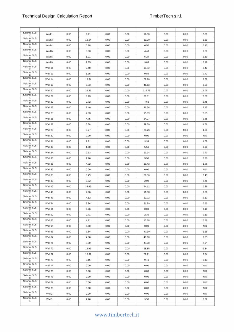
Technical Design Calculation Report TimberTech s.r.l.
www.timbertech.it
Seismic SLS
X Wall 1 0.00 2.71 0.00 0.00 16.30 0.00 0.00 2.59
Seismic SLS X Wall 3 0.00 13.54 0.00 0.00 69.90 0.00 0.00 2.59
Seismic SLS X Wall 4 0.00 0.28 0.00 0.00 0.50 0.00 0.00 0.10
Seismic SLS X Wall 6 0.00 0.33 0.00 0.00 4.43 0.00 0.00 0.20
Seismic SLS X Wall 8 0.00 1.01 0.00 0.00 5.24 0.00 0.00 2.59
Seismic SLS X Wall 9 0.00 1.35 0.00 0.00 9.83 0.00 0.00 0.42
Seismic SLS X Wall 11 0.00 2.40 0.00 0.00 18.82 0.00 0.00 0.42
Seismic SLS X Wall 13 0.00 1.35 0.00 0.00 9.89 0.00 0.00 0.42
Seismic SLS X Wall 14 0.00 13.54 0.00 0.00 69.90 0.00 0.00 2.59
Seismic SLS X Wall 15 0.00 8.73 0.00 0.00 41.12 0.00 0.00 2.09
Seismic SLS X Wall 20 0.00 38.31 0.00 0.00 216.71 0.00 0.00 2.09
Seismic SLS X Wall 21 0.00 8.73 0.00 0.00 39.31 0.00 0.00 2.09
Seismic SLS X Wall 22 0.00 2.72 0.00 0.00 7.62 0.00 0.00 2.45
Seismic SLS X Wall 23 0.00 9.49 0.00 0.00 26.56 0.00 0.00 2.45
Seismic SLS X Wall 25 0.00 4.83 0.00 0.00 15.09 0.00 0.00 2.65
Seismic SLS X Wall 26 0.00 4.75 0.00 0.00 14.97 0.00 0.00 2.65
Seismic SLS X Wall 27 0.00 6.58 0.00 0.00 29.59 0.00 0.00 1.66
Seismic SLS X Wall 29 0.00 6.27 0.00 0.00 28.23 0.00 0.00 1.66
Seismic SLS X Wall 30 0.00 0.00 0.00 0.00 0.00 0.00 0.00 N/D
Seismic SLS X Wall 31 0.00 1.21 0.00 0.00 3.39 0.00 0.00 1.09
Seismic SLS X Wall 33 0.00 1.80 0.00 0.00 5.56 0.00 0.00 0.90
Seismic SLS X Wall 34 0.00 2.63 0.00 0.00 11.14 0.00 0.00 0.90
Seismic SLS X Wall 35 0.00 1.76 0.00 0.00 5.50 0.00 0.00 0.90
Seismic SLS X Wall 36 0.00 4.32 0.00 0.00 19.42 0.00 0.00 1.66
Seismic SLS X Wall 37 0.00 0.00 0.00 0.00 0.00 0.00 0.00 N/D
Seismic SLS X Wall 38 0.00 9.49 0.00 0.00 26.56 0.00 0.00 2.45
Seismic SLS X Wall 39 0.00 0.72 0.00 0.00 2.02 0.00 0.00 2.45
Seismic SLS X Wall 42 0.00 33.62 0.00 0.00 94.12 0.00 0.00 0.86
Seismic SLS X Wall 43 0.00 4.06 0.00 0.00 11.38 0.00 0.00 0.86
Seismic SLS X Wall 46 0.00 4.13 0.00 0.00 12.92 0.00 0.00 2.13
Seismic SLS X Wall 54 0.00 2.84 0.00 0.00 21.99 0.00 0.00 0.52
Seismic SLS X Wall 61 0.00 0.76 0.00 0.00 0.08 0.00 0.00 0.10
Seismic SLS X Wall 62 0.00 0.71 0.00 0.00 2.36 0.00 0.00 0.13
Seismic SLS X Wall 63 0.00 4.71 0.00 0.00 13.18 0.00 0.00 0.86
Seismic SLS X Wall 64 0.00 0.00 0.00 0.00 0.00 0.00 0.00 N/D
Seismic SLS X Wall 66 0.00 7.88 0.00 0.00 40.30 0.00 0.00 2.65
Seismic SLS X Wall 67 0.00 7.88 0.00 0.00 40.18 0.00 0.00 2.65
Seismic SLS X Wall 71 0.00 8.70 0.00 0.00 47.28 0.00 0.00 2.34
Seismic SLS X Wall 72 0.00 12.69 0.00 0.00 68.85 0.00 0.00 2.34
Seismic SLS X Wall 72 0.00 13.32 0.00 0.00 72.21 0.00 0.00 2.34
Seismic SLS X Wall 73 0.00 0.15 0.00 0.00 0.41 0.00 0.00 0.13
Seismic SLS X Wall 74 0.00 0.00 0.00 0.00 0.00 0.00 0.00 N/D
Seismic SLS X Wall 75 0.00 0.00 0.00 0.00 0.00 0.00 0.00 N/D
Seismic SLS X Wall 76 0.00 0.00 0.00 0.00 0.00 0.00 0.00 N/D
Seismic SLS X Wall 77 0.00 0.00 0.00 0.00 0.00 0.00 0.00 N/D
Seismic SLS X Wall 78 0.00 0.00 0.00 0.00 0.00 0.00 0.00 N/D
Seismic SLS X Wall2 0.00 0.00 0.00 0.00 0.00 0.00 0.00 N/D
Seismic SLS X Wall3 0.00 2.98 0.00 0.00 9.55 0.00 0.00 0.52

Technical Design Calculation Report TimberTech s.r.l.
www.timbertech.it
Seismic SLS Y Wall 1 0.00 0.16 0.00 0.00 4.68 0.00 0.00 0.15
Seismic SLS Y Wall 3 0.00 0.80 0.00 0.00 17.08 0.00 0.00 0.15
Seismic SLS Y Wall 4 0.00 10.68 0.00 0.00 51.96 0.00 0.00 3.84
Seismic SLS Y Wall 6 0.00 6.60 0.00 0.00 42.28 0.00 0.00 4.00
Seismic SLS Y Wall 8 0.00 0.06 0.00 0.00 1.29 0.00 0.00 0.15
Seismic SLS Y Wall 9 0.00 11.68 0.00 0.00 65.08 0.00 0.00 3.66
Seismic SLS Y Wall 11 0.00 20.71 0.00 0.00 122.40 0.00 0.00 3.66
Seismic SLS Y Wall 13 0.00 11.68 0.00 0.00 65.38 0.00 0.00 3.66
Seismic SLS Y Wall 14 0.00 0.80 0.00 0.00 17.08 0.00 0.00 0.15
Seismic SLS Y Wall 15 0.00 0.50 0.00 0.00 8.58 0.00 0.00 0.12
Seismic SLS Y Wall 20 0.00 2.19 0.00 0.00 56.88 0.00 0.00 0.12
Seismic SLS Y Wall 21 0.00 0.50 0.00 0.00 7.63 0.00 0.00 0.12
Seismic SLS Y Wall 22 0.00 1.49 0.00 0.00 4.16 0.00 0.00 1.34
Seismic SLS Y Wall 23 0.00 5.18 0.00 0.00 14.50 0.00 0.00 1.34
Seismic SLS Y Wall 25 0.00 2.84 0.00 0.00 8.88 0.00 0.00 1.56
Seismic SLS Y Wall 26 0.00 2.79 0.00 0.00 8.81 0.00 0.00 1.56
Seismic SLS Y Wall 27 0.00 1.75 0.00 0.00 7.89 0.00 0.00 0.44
Seismic SLS Y Wall 29 0.00 1.67 0.00 0.00 7.52 0.00 0.00 0.44
Seismic SLS Y Wall 30 0.00 0.00 0.00 0.00 0.00 0.00 0.00 N/D
Seismic SLS Y Wall 31 0.00 7.55 0.00 0.00 21.15 0.00 0.00 6.81
Seismic SLS Y Wall 33 0.00 9.07 0.00 0.00 28.00 0.00 0.00 4.56
Seismic SLS Y Wall 34 0.00 13.26 0.00 0.00 56.13 0.00 0.00 4.56
Seismic SLS Y Wall 35 0.00 8.86 0.00 0.00 27.70 0.00 0.00 4.56
Seismic SLS Y Wall 36 0.00 1.15 0.00 0.00 5.18 0.00 0.00 0.44
Seismic SLS Y Wall 37 0.00 0.00 0.00 0.00 0.00 0.00 0.00 N/D
Seismic SLS Y Wall 38 0.00 5.18 0.00 0.00 14.50 0.00 0.00 1.34
Seismic SLS Y Wall 39 0.00 0.39 0.00 0.00 1.10 0.00 0.00 1.34
Seismic SLS Y Wall 42 0.00 17.81 0.00 0.00 49.86 0.00 0.00 0.46
Seismic SLS Y Wall 43 0.00 2.15 0.00 0.00 6.03 0.00 0.00 0.46
Seismic SLS Y Wall 46 0.00 15.50 0.00 0.00 48.48 0.00 0.00 7.98
Seismic SLS Y Wall 54 0.00 22.81 0.00 0.00 121.47 0.00 0.00 4.18
Seismic SLS Y Wall 61 0.00 28.87 0.00 0.00 195.55 0.00 0.00 3.84
Seismic SLS Y Wall 62 0.00 30.96 0.00 0.00 103.17 0.00 0.00 5.73
Seismic SLS Y Wall 63 0.00 2.49 0.00 0.00 6.98 0.00 0.00 0.46
Seismic SLS Y Wall 64 0.00 0.00 0.00 0.00 0.00 0.00 0.00 N/D
Seismic SLS Y Wall 66 0.00 0.56 0.00 0.00 10.65 0.00 0.00 0.19
Seismic SLS Y Wall 67 0.00 0.56 0.00 0.00 10.59 0.00 0.00 0.19
Seismic SLS Y Wall 71 0.00 0.06 0.00 0.00 5.38 0.00 0.00 0.02
Seismic SLS Y Wall 72 0.00 0.09 0.00 0.00 7.82 0.00 0.00 0.02
Seismic SLS Y Wall 72 0.00 0.10 0.00 0.00 8.20 0.00 0.00 0.02
Seismic SLS Y Wall 73 0.00 6.35 0.00 0.00 17.79 0.00 0.00 5.73
Seismic SLS Y Wall 74 0.00 0.00 0.00 0.00 0.00 0.00 0.00 N/D
Seismic SLS Y Wall 75 0.00 0.00 0.00 0.00 0.00 0.00 0.00 N/D
Seismic SLS Y Wall 76 0.00 0.00 0.00 0.00 0.00 0.00 0.00 N/D
Seismic SLS Y Wall 77 0.00 0.00 0.00 0.00 0.00 0.00 0.00 N/D
Seismic SLS Y Wall 78 0.00 0.00 0.00 0.00 0.00 0.00 0.00 N/D
Seismic SLS Y Wall2 0.00 0.00 0.00 0.00 0.00 0.00 0.00 N/D
Seismic SLS Y Wall3 0.00 24.02 0.00 0.00 76.85 0.00 0.00 4.18

Technical Design Calculation Report TimberTech s.r.l.
www.timbertech.it
Columns
Column name: Column ID
N: Total axial force
Load Column name N [kN]
G1 Column 1 4.11 G1 Column 2 14.12 G1 Column 3 4.13 G1 Column 6 6.87 G1 Column 7 2.39 G1 Column 9 2.40 G1 Column 10 6.99 G1 Column 12 6.95 G1 Column 11 17.92
G2 Column 1 6.86 G2 Column 2 35.02 G2 Column 3 6.91 G2 Column 6 21.95 G2 Column 7 5.35 G2 Column 9 5.37 G2 Column 10 19.91 G2 Column 12 17.08 G2 Column 11 35.88
Variable cat.A Column 1 6.86 Variable cat.A Column 2 35.02 Variable cat.A Column 3 6.91 Variable cat.A Column 6 0.00 Variable cat.A Column 7 5.35 Variable cat.A Column 9 5.37 Variable cat.A Column 10 19.91 Variable cat.A Column 12 10.85 Variable cat.A Column 11 35.87
Variable cat.H Column 1 0.00 Variable cat.H Column 2 0.00 Variable cat.H Column 3 0.00 Variable cat.H Column 6 5.49 Variable cat.H Column 7 0.00 Variable cat.H Column 9 0.00 Variable cat.H Column 10 0.00 Variable cat.H Column 12 1.56 Variable cat.H Column 11 0.00
Snow Column 1 0.00 Snow Column 2 0.00 Snow Column 3 0.00 Snow Column 6 12.19 Snow Column 7 0.00 Snow Column 9 0.00 Snow Column 10 0.00 Snow Column 12 3.46 Snow Column 11 0.00
Orthogonal wind Column 1 0.00 Orthogonal wind Column 2 0.00 Orthogonal wind Column 3 0.00 Orthogonal wind Column 6 -2.74 Orthogonal wind Column 7 0.00 Orthogonal wind Column 9 0.00 Orthogonal wind Column 10 0.00 Orthogonal wind Column 12 -0.78 Orthogonal wind Column 11 0.00
Wind X Column 1 0.00 Wind X Column 2 0.00 Wind X Column 3 0.00 Wind X Column 6 0.00 Wind X Column 7 0.00 Wind X Column 9 0.00 Wind X Column 10 0.00 Wind X Column 12 0.00

Technical Design Calculation Report TimberTech s.r.l.
www.timbertech.it
Wind X Column 11 0.00
Wind Y Column 1 0.00 Wind Y Column 2 0.00 Wind Y Column 3 0.00 Wind Y Column 6 0.00 Wind Y Column 7 0.00 Wind Y Column 9 0.00 Wind Y Column 10 0.00 Wind Y Column 12 0.00 Wind Y Column 11 0.00
Seismic ULS X Column 1 0.00 Seismic ULS X Column 2 0.00 Seismic ULS X Column 3 0.00 Seismic ULS X Column 6 0.00 Seismic ULS X Column 7 0.00 Seismic ULS X Column 9 0.00 Seismic ULS X Column 10 0.00 Seismic ULS X Column 12 0.00 Seismic ULS X Column 11 0.00
Seismic ULS Y Column 1 0.00 Seismic ULS Y Column 2 0.00 Seismic ULS Y Column 3 0.00 Seismic ULS Y Column 6 0.00 Seismic ULS Y Column 7 0.00 Seismic ULS Y Column 9 0.00 Seismic ULS Y Column 10 0.00 Seismic ULS Y Column 12 0.00 Seismic ULS Y Column 11 0.00
Seismic SLS X Column 1 0.00 Seismic SLS X Column 2 0.00 Seismic SLS X Column 3 0.00 Seismic SLS X Column 6 0.00 Seismic SLS X Column 7 0.00 Seismic SLS X Column 9 0.00 Seismic SLS X Column 10 0.00 Seismic SLS X Column 12 0.00 Seismic SLS X Column 11 0.00
Seismic SLS Y Column 1 0.00 Seismic SLS Y Column 2 0.00 Seismic SLS Y Column 3 0.00 Seismic SLS Y Column 6 0.00 Seismic SLS Y Column 7 0.00 Seismic SLS Y Column 9 0.00 Seismic SLS Y Column 10 0.00 Seismic SLS Y Column 12 0.00 Seismic SLS Y Column 11 0.00
Floors
Floor name: Floor ID
V2: Maximum shear stress along the local axis 2 for the most stressed element of the floor
M3-3: Maximum bending moment around local axis 3 for the most stressed element of the floor
wist: Maximum deformation for the most stressed element of the floor

Technical Design Calculation Report TimberTech s.r.l.
www.timbertech.it
Load Floor name V2 [kN]
M3-3 [kNm]
wist [mm]
G1 Floor 1 1.81 1.51 0.62 G1 Floor 3 0.50 0.48 -0.29 G1 Floor 12 0.29 0.20 0.07 G1 Floor 13 0.29 0.20 0.07 G1 Floor 14 0.50 0.49 -0.29 G1 Floor 15 0.83 0.51 0.17
G2 Floor 1 5.17 4.31 1.76 G2 Floor 3 2.60 2.52 -1.52 G2 Floor 12 1.49 1.03 0.38 G2 Floor 13 1.49 1.03 0.38 G2 Floor 14 2.61 2.54 -1.52 G2 Floor 15 2.38 1.44 0.48
Variable cat.A Floor 1 5.17 4.31 1.76 Variable cat.A Floor 3 0.00 0.00 0.00 Variable cat.A Floor 12 1.49 1.03 0.38 Variable cat.A Floor 13 1.49 1.03 0.38 Variable cat.A Floor 14 0.00 0.00 0.00 Variable cat.A Floor 15 2.38 1.44 0.48
Variable cat.H Floor 1 0.00 0.00 0.00 Variable cat.H Floor 3 0.65 0.63 -0.38 Variable cat.H Floor 12 0.00 0.00 0.00 Variable cat.H Floor 13 0.00 0.00 0.00 Variable cat.H Floor 14 0.65 0.64 -0.38 Variable cat.H Floor 15 0.00 0.00 0.00
Snow Floor 1 0.00 0.00 0.00 Snow Floor 3 1.44 1.40 -0.84 Snow Floor 12 0.00 0.00 0.00 Snow Floor 13 0.00 0.00 0.00 Snow Floor 14 1.45 1.41 -0.84 Snow Floor 15 0.00 0.00 0.00
Orthogonal wind Floor 1 0.00 0.00 0.00 Orthogonal wind Floor 3 0.32 0.32 0.19 Orthogonal wind Floor 12 0.00 0.00 0.00 Orthogonal wind Floor 13 0.00 0.00 0.00 Orthogonal wind Floor 14 0.33 0.32 0.19 Orthogonal wind Floor 15 0.00 0.00 0.00
Wind X Floor 1 0.00 0.00 0.00 Wind X Floor 3 0.00 0.00 0.00 Wind X Floor 12 0.00 0.00 0.00 Wind X Floor 13 0.00 0.00 0.00 Wind X Floor 14 0.00 0.00 0.00 Wind X Floor 15 0.00 0.00 0.00
Wind Y Floor 1 0.00 0.00 0.00 Wind Y Floor 3 0.00 0.00 0.00 Wind Y Floor 12 0.00 0.00 0.00 Wind Y Floor 13 0.00 0.00 0.00 Wind Y Floor 14 0.00 0.00 0.00 Wind Y Floor 15 0.00 0.00 0.00
Seismic ULS X Floor 1 0.00 0.00 0.00 Seismic ULS X Floor 3 0.00 0.00 0.00 Seismic ULS X Floor 12 0.00 0.00 0.00 Seismic ULS X Floor 13 0.00 0.00 0.00 Seismic ULS X Floor 14 0.00 0.00 0.00 Seismic ULS X Floor 15 0.00 0.00 0.00
Seismic ULS Y Floor 1 0.00 0.00 0.00 Seismic ULS Y Floor 3 0.00 0.00 0.00 Seismic ULS Y Floor 12 0.00 0.00 0.00 Seismic ULS Y Floor 13 0.00 0.00 0.00 Seismic ULS Y Floor 14 0.00 0.00 0.00 Seismic ULS Y Floor 15 0.00 0.00 0.00
Seismic SLS X Floor 1 0.00 0.00 0.00 Seismic SLS X Floor 3 0.00 0.00 0.00 Seismic SLS X Floor 12 0.00 0.00 0.00 Seismic SLS X Floor 13 0.00 0.00 0.00 Seismic SLS X Floor 14 0.00 0.00 0.00 Seismic SLS X Floor 15 0.00 0.00 0.00
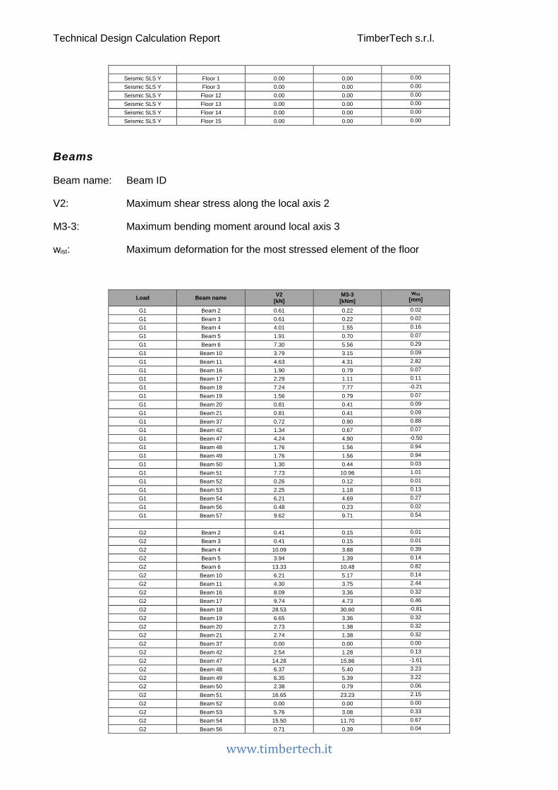
Technical Design Calculation Report TimberTech s.r.l.
www.timbertech.it
Seismic SLS Y Floor 1 0.00 0.00 0.00 Seismic SLS Y Floor 3 0.00 0.00 0.00 Seismic SLS Y Floor 12 0.00 0.00 0.00 Seismic SLS Y Floor 13 0.00 0.00 0.00 Seismic SLS Y Floor 14 0.00 0.00 0.00 Seismic SLS Y Floor 15 0.00 0.00 0.00
Beams
Beam name: Beam ID
V2: Maximum shear stress along the local axis 2
M3-3: Maximum bending moment around local axis 3
wist: Maximum deformation for the most stressed element of the floor
Load Beam name V2 [kN]
M3-3 [kNm]
wist [mm]
G1 Beam 2 0.61 0.22 0.02 G1 Beam 3 0.61 0.22 0.02 G1 Beam 4 4.01 1.55 0.16 G1 Beam 5 1.91 0.70 0.07 G1 Beam 6 7.30 5.56 0.29 G1 Beam 10 3.79 3.15 0.09 G1 Beam 11 4.63 4.31 2.82 G1 Beam 16 1.90 0.79 0.07 G1 Beam 17 2.29 1.11 0.11 G1 Beam 18 7.24 7.77 -0.21 G1 Beam 19 1.56 0.79 0.07 G1 Beam 20 0.81 0.41 0.09 G1 Beam 21 0.81 0.41 0.09 G1 Beam 37 0.72 0.90 0.88 G1 Beam 42 1.34 0.67 0.07 G1 Beam 47 4.24 4.90 -0.50 G1 Beam 48 1.76 1.56 0.94 G1 Beam 49 1.76 1.56 0.94 G1 Beam 50 1.30 0.44 0.03 G1 Beam 51 7.73 10.96 1.01 G1 Beam 52 0.26 0.12 0.01 G1 Beam 53 2.25 1.18 0.13 G1 Beam 54 6.21 4.69 0.27 G1 Beam 56 0.48 0.23 0.02 G1 Beam 57 9.62 9.71 0.54
G2 Beam 2 0.41 0.15 0.01 G2 Beam 3 0.41 0.15 0.01 G2 Beam 4 10.09 3.88 0.39 G2 Beam 5 3.94 1.39 0.14 G2 Beam 6 13.33 10.48 0.82 G2 Beam 10 6.21 5.17 0.14 G2 Beam 11 4.30 3.75 2.44 G2 Beam 16 8.09 3.36 0.32 G2 Beam 17 9.74 4.73 0.46 G2 Beam 18 28.53 30.60 -0.81 G2 Beam 19 6.65 3.36 0.32 G2 Beam 20 2.73 1.38 0.32 G2 Beam 21 2.74 1.38 0.32 G2 Beam 37 0.00 0.00 0.00 G2 Beam 42 2.54 1.28 0.13 G2 Beam 47 14.28 15.86 -1.61 G2 Beam 48 6.37 5.40 3.23 G2 Beam 49 6.35 5.39 3.22 G2 Beam 50 2.38 0.79 0.06 G2 Beam 51 16.65 23.23 2.15 G2 Beam 52 0.00 0.00 0.00 G2 Beam 53 5.76 3.08 0.33 G2 Beam 54 15.50 11.70 0.67 G2 Beam 56 0.71 0.39 0.04
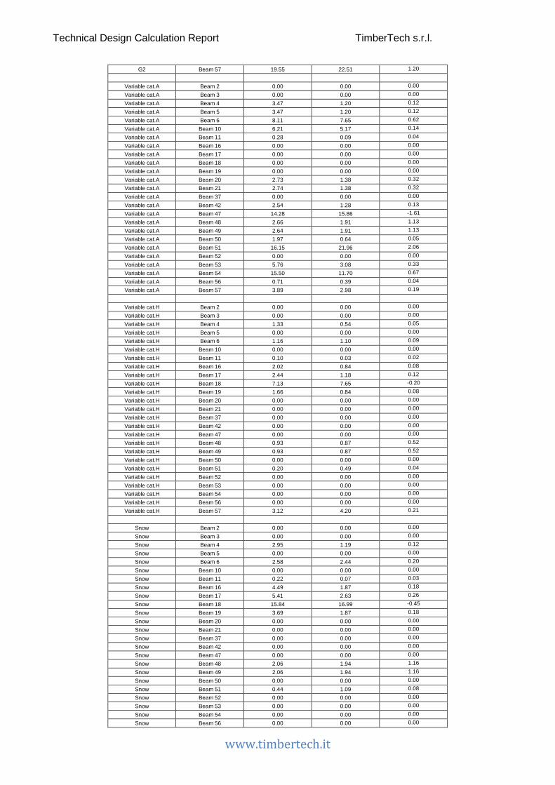
Technical Design Calculation Report TimberTech s.r.l.
www.timbertech.it
G2 Beam 57 19.55 22.51 1.20
Variable cat.A Beam 2 0.00 0.00 0.00 Variable cat.A Beam 3 0.00 0.00 0.00 Variable cat.A Beam 4 3.47 1.20 0.12 Variable cat.A Beam 5 3.47 1.20 0.12 Variable cat.A Beam 6 8.11 7.65 0.62 Variable cat.A Beam 10 6.21 5.17 0.14 Variable cat.A Beam 11 0.28 0.09 0.04 Variable cat.A Beam 16 0.00 0.00 0.00 Variable cat.A Beam 17 0.00 0.00 0.00 Variable cat.A Beam 18 0.00 0.00 0.00 Variable cat.A Beam 19 0.00 0.00 0.00 Variable cat.A Beam 20 2.73 1.38 0.32 Variable cat.A Beam 21 2.74 1.38 0.32 Variable cat.A Beam 37 0.00 0.00 0.00 Variable cat.A Beam 42 2.54 1.28 0.13 Variable cat.A Beam 47 14.28 15.86 -1.61 Variable cat.A Beam 48 2.66 1.91 1.13 Variable cat.A Beam 49 2.64 1.91 1.13 Variable cat.A Beam 50 1.97 0.64 0.05 Variable cat.A Beam 51 16.15 21.96 2.06 Variable cat.A Beam 52 0.00 0.00 0.00 Variable cat.A Beam 53 5.76 3.08 0.33 Variable cat.A Beam 54 15.50 11.70 0.67 Variable cat.A Beam 56 0.71 0.39 0.04 Variable cat.A Beam 57 3.89 2.98 0.19
Variable cat.H Beam 2 0.00 0.00 0.00 Variable cat.H Beam 3 0.00 0.00 0.00 Variable cat.H Beam 4 1.33 0.54 0.05 Variable cat.H Beam 5 0.00 0.00 0.00 Variable cat.H Beam 6 1.16 1.10 0.09 Variable cat.H Beam 10 0.00 0.00 0.00 Variable cat.H Beam 11 0.10 0.03 0.02 Variable cat.H Beam 16 2.02 0.84 0.08 Variable cat.H Beam 17 2.44 1.18 0.12 Variable cat.H Beam 18 7.13 7.65 -0.20 Variable cat.H Beam 19 1.66 0.84 0.08 Variable cat.H Beam 20 0.00 0.00 0.00 Variable cat.H Beam 21 0.00 0.00 0.00 Variable cat.H Beam 37 0.00 0.00 0.00 Variable cat.H Beam 42 0.00 0.00 0.00 Variable cat.H Beam 47 0.00 0.00 0.00 Variable cat.H Beam 48 0.93 0.87 0.52 Variable cat.H Beam 49 0.93 0.87 0.52 Variable cat.H Beam 50 0.00 0.00 0.00 Variable cat.H Beam 51 0.20 0.49 0.04 Variable cat.H Beam 52 0.00 0.00 0.00 Variable cat.H Beam 53 0.00 0.00 0.00 Variable cat.H Beam 54 0.00 0.00 0.00 Variable cat.H Beam 56 0.00 0.00 0.00 Variable cat.H Beam 57 3.12 4.20 0.21
Snow Beam 2 0.00 0.00 0.00 Snow Beam 3 0.00 0.00 0.00 Snow Beam 4 2.95 1.19 0.12 Snow Beam 5 0.00 0.00 0.00 Snow Beam 6 2.58 2.44 0.20 Snow Beam 10 0.00 0.00 0.00 Snow Beam 11 0.22 0.07 0.03 Snow Beam 16 4.49 1.87 0.18 Snow Beam 17 5.41 2.63 0.26 Snow Beam 18 15.84 16.99 -0.45 Snow Beam 19 3.69 1.87 0.18 Snow Beam 20 0.00 0.00 0.00 Snow Beam 21 0.00 0.00 0.00 Snow Beam 37 0.00 0.00 0.00 Snow Beam 42 0.00 0.00 0.00 Snow Beam 47 0.00 0.00 0.00 Snow Beam 48 2.06 1.94 1.16 Snow Beam 49 2.06 1.94 1.16 Snow Beam 50 0.00 0.00 0.00 Snow Beam 51 0.44 1.09 0.08 Snow Beam 52 0.00 0.00 0.00 Snow Beam 53 0.00 0.00 0.00 Snow Beam 54 0.00 0.00 0.00 Snow Beam 56 0.00 0.00 0.00

Technical Design Calculation Report TimberTech s.r.l.
www.timbertech.it
Snow Beam 57 6.93 9.33 0.47
Orthogonal wind Beam 2 0.00 0.00 0.00 Orthogonal wind Beam 3 0.00 0.00 0.00 Orthogonal wind Beam 4 0.66 0.27 -0.03 Orthogonal wind Beam 5 0.00 0.00 0.00 Orthogonal wind Beam 6 0.58 0.55 -0.04 Orthogonal wind Beam 10 0.00 0.00 0.00 Orthogonal wind Beam 11 0.05 0.02 -0.01 Orthogonal wind Beam 16 1.01 0.42 -0.04 Orthogonal wind Beam 17 1.22 0.59 -0.06 Orthogonal wind Beam 18 3.56 3.82 0.10 Orthogonal wind Beam 19 0.83 0.42 -0.04 Orthogonal wind Beam 20 0.00 0.00 0.00 Orthogonal wind Beam 21 0.00 0.00 0.00 Orthogonal wind Beam 37 0.00 0.00 0.00 Orthogonal wind Beam 42 0.00 0.00 0.00 Orthogonal wind Beam 47 0.00 0.00 0.00 Orthogonal wind Beam 48 0.46 0.44 -0.26 Orthogonal wind Beam 49 0.46 0.44 -0.26 Orthogonal wind Beam 50 0.00 0.00 0.00 Orthogonal wind Beam 51 0.10 0.25 -0.02 Orthogonal wind Beam 52 0.00 0.00 0.00 Orthogonal wind Beam 53 0.00 0.00 0.00 Orthogonal wind Beam 54 0.00 0.00 0.00 Orthogonal wind Beam 56 0.00 0.00 0.00 Orthogonal wind Beam 57 1.56 2.10 -0.10
Wind X Beam 2 0.00 0.00 0.00 Wind X Beam 3 0.00 0.00 0.00 Wind X Beam 4 0.00 0.00 0.00 Wind X Beam 5 0.00 0.00 0.00 Wind X Beam 6 0.00 0.00 0.00 Wind X Beam 10 0.00 0.00 0.00 Wind X Beam 11 0.00 0.00 0.00 Wind X Beam 16 0.00 0.00 0.00 Wind X Beam 17 0.00 0.00 0.00 Wind X Beam 18 0.00 0.00 0.00 Wind X Beam 19 0.00 0.00 0.00 Wind X Beam 20 0.00 0.00 0.00 Wind X Beam 21 0.00 0.00 0.00 Wind X Beam 37 0.00 0.00 0.00 Wind X Beam 42 0.00 0.00 0.00 Wind X Beam 47 0.00 0.00 0.00 Wind X Beam 48 0.00 0.00 0.00 Wind X Beam 49 0.00 0.00 0.00 Wind X Beam 50 0.00 0.00 0.00 Wind X Beam 51 0.00 0.00 0.00 Wind X Beam 52 0.00 0.00 0.00 Wind X Beam 53 0.00 0.00 0.00 Wind X Beam 54 0.00 0.00 0.00 Wind X Beam 56 0.00 0.00 0.00 Wind X Beam 57 0.00 0.00 0.00
Wind Y Beam 2 0.00 0.00 0.00 Wind Y Beam 3 0.00 0.00 0.00 Wind Y Beam 4 0.00 0.00 0.00 Wind Y Beam 5 0.00 0.00 0.00 Wind Y Beam 6 0.00 0.00 0.00 Wind Y Beam 10 0.00 0.00 0.00 Wind Y Beam 11 0.00 0.00 0.00 Wind Y Beam 16 0.00 0.00 0.00 Wind Y Beam 17 0.00 0.00 0.00 Wind Y Beam 18 0.00 0.00 0.00 Wind Y Beam 19 0.00 0.00 0.00 Wind Y Beam 20 0.00 0.00 0.00 Wind Y Beam 21 0.00 0.00 0.00 Wind Y Beam 37 0.00 0.00 0.00 Wind Y Beam 42 0.00 0.00 0.00 Wind Y Beam 47 0.00 0.00 0.00 Wind Y Beam 48 0.00 0.00 0.00 Wind Y Beam 49 0.00 0.00 0.00 Wind Y Beam 50 0.00 0.00 0.00 Wind Y Beam 51 0.00 0.00 0.00 Wind Y Beam 52 0.00 0.00 0.00 Wind Y Beam 53 0.00 0.00 0.00 Wind Y Beam 54 0.00 0.00 0.00 Wind Y Beam 56 0.00 0.00 0.00
Technical Design Calculation Report TimberTech s.r.l.
www.timbertech.it
Wind Y Beam 57 0.00 0.00 0.00
Seismic ULS X Beam 2 0.00 0.00 0.00 Seismic ULS X Beam 3 0.00 0.00 0.00 Seismic ULS X Beam 4 0.00 0.00 0.00 Seismic ULS X Beam 5 0.00 0.00 0.00 Seismic ULS X Beam 6 0.00 0.00 0.00 Seismic ULS X Beam 10 0.00 0.00 0.00 Seismic ULS X Beam 11 0.00 0.00 0.00 Seismic ULS X Beam 16 0.00 0.00 0.00 Seismic ULS X Beam 17 0.00 0.00 0.00 Seismic ULS X Beam 18 0.00 0.00 0.00 Seismic ULS X Beam 19 0.00 0.00 0.00 Seismic ULS X Beam 20 0.00 0.00 0.00 Seismic ULS X Beam 21 0.00 0.00 0.00 Seismic ULS X Beam 37 0.00 0.00 0.00 Seismic ULS X Beam 42 0.00 0.00 0.00 Seismic ULS X Beam 47 0.00 0.00 0.00 Seismic ULS X Beam 48 0.00 0.00 0.00 Seismic ULS X Beam 49 0.00 0.00 0.00 Seismic ULS X Beam 50 0.00 0.00 0.00 Seismic ULS X Beam 51 0.00 0.00 0.00 Seismic ULS X Beam 52 0.00 0.00 0.00 Seismic ULS X Beam 53 0.00 0.00 0.00 Seismic ULS X Beam 54 0.00 0.00 0.00 Seismic ULS X Beam 56 0.00 0.00 0.00 Seismic ULS X Beam 57 0.00 0.00 0.00
Seismic ULS Y Beam 2 0.00 0.00 0.00 Seismic ULS Y Beam 3 0.00 0.00 0.00 Seismic ULS Y Beam 4 0.00 0.00 0.00 Seismic ULS Y Beam 5 0.00 0.00 0.00 Seismic ULS Y Beam 6 0.00 0.00 0.00 Seismic ULS Y Beam 10 0.00 0.00 0.00 Seismic ULS Y Beam 11 0.00 0.00 0.00 Seismic ULS Y Beam 16 0.00 0.00 0.00 Seismic ULS Y Beam 17 0.00 0.00 0.00 Seismic ULS Y Beam 18 0.00 0.00 0.00 Seismic ULS Y Beam 19 0.00 0.00 0.00 Seismic ULS Y Beam 20 0.00 0.00 0.00 Seismic ULS Y Beam 21 0.00 0.00 0.00 Seismic ULS Y Beam 37 0.00 0.00 0.00 Seismic ULS Y Beam 42 0.00 0.00 0.00 Seismic ULS Y Beam 47 0.00 0.00 0.00 Seismic ULS Y Beam 48 0.00 0.00 0.00 Seismic ULS Y Beam 49 0.00 0.00 0.00 Seismic ULS Y Beam 50 0.00 0.00 0.00 Seismic ULS Y Beam 51 0.00 0.00 0.00 Seismic ULS Y Beam 52 0.00 0.00 0.00 Seismic ULS Y Beam 53 0.00 0.00 0.00 Seismic ULS Y Beam 54 0.00 0.00 0.00 Seismic ULS Y Beam 56 0.00 0.00 0.00 Seismic ULS Y Beam 57 0.00 0.00 0.00
Seismic SLS X Beam 2 0.00 0.00 0.00 Seismic SLS X Beam 3 0.00 0.00 0.00 Seismic SLS X Beam 4 0.00 0.00 0.00 Seismic SLS X Beam 5 0.00 0.00 0.00 Seismic SLS X Beam 6 0.00 0.00 0.00 Seismic SLS X Beam 10 0.00 0.00 0.00 Seismic SLS X Beam 11 0.00 0.00 0.00 Seismic SLS X Beam 16 0.00 0.00 0.00 Seismic SLS X Beam 17 0.00 0.00 0.00 Seismic SLS X Beam 18 0.00 0.00 0.00 Seismic SLS X Beam 19 0.00 0.00 0.00 Seismic SLS X Beam 20 0.00 0.00 0.00 Seismic SLS X Beam 21 0.00 0.00 0.00 Seismic SLS X Beam 37 0.00 0.00 0.00 Seismic SLS X Beam 42 0.00 0.00 0.00 Seismic SLS X Beam 47 0.00 0.00 0.00 Seismic SLS X Beam 48 0.00 0.00 0.00 Seismic SLS X Beam 49 0.00 0.00 0.00 Seismic SLS X Beam 50 0.00 0.00 0.00 Seismic SLS X Beam 51 0.00 0.00 0.00 Seismic SLS X Beam 52 0.00 0.00 0.00 Seismic SLS X Beam 53 0.00 0.00 0.00 Seismic SLS X Beam 54 0.00 0.00 0.00 Seismic SLS X Beam 56 0.00 0.00 0.00
Technical Design Calculation Report TimberTech s.r.l.
www.timbertech.it
Seismic SLS X Beam 57 0.00 0.00 0.00
Seismic SLS Y Beam 2 0.00 0.00 0.00 Seismic SLS Y Beam 3 0.00 0.00 0.00 Seismic SLS Y Beam 4 0.00 0.00 0.00 Seismic SLS Y Beam 5 0.00 0.00 0.00 Seismic SLS Y Beam 6 0.00 0.00 0.00 Seismic SLS Y Beam 10 0.00 0.00 0.00 Seismic SLS Y Beam 11 0.00 0.00 0.00 Seismic SLS Y Beam 16 0.00 0.00 0.00 Seismic SLS Y Beam 17 0.00 0.00 0.00 Seismic SLS Y Beam 18 0.00 0.00 0.00 Seismic SLS Y Beam 19 0.00 0.00 0.00 Seismic SLS Y Beam 20 0.00 0.00 0.00 Seismic SLS Y Beam 21 0.00 0.00 0.00 Seismic SLS Y Beam 37 0.00 0.00 0.00 Seismic SLS Y Beam 42 0.00 0.00 0.00 Seismic SLS Y Beam 47 0.00 0.00 0.00 Seismic SLS Y Beam 48 0.00 0.00 0.00 Seismic SLS Y Beam 49 0.00 0.00 0.00 Seismic SLS Y Beam 50 0.00 0.00 0.00 Seismic SLS Y Beam 51 0.00 0.00 0.00 Seismic SLS Y Beam 52 0.00 0.00 0.00 Seismic SLS Y Beam 53 0.00 0.00 0.00 Seismic SLS Y Beam 54 0.00 0.00 0.00 Seismic SLS Y Beam 56 0.00 0.00 0.00 Seismic SLS Y Beam 57 0.00 0.00 0.00

Technical Design Calculation Report TimberTech s.r.l.
www.timbertech.it
Forces and moments acting on foundations In this chapter are reported the values of actions acting at the base of the walls and columns of the ground floor. They refer to the ULS combination that maximizes the axial loads and to the different loads considered individually.
Walls
Wall name: Wall ID
N: Total axial force
V2: Shear force (in-plane)
V3: Shear force (out-of-plane)
M2-2: Bending moment (out-of-plane)
M3-3: Bending moment (in-plane)
Wall name Length [m] Load / Comb. N
[kN] V2
[kN] V3
[kN] M2-2
[kNm] M3-3
[kNm] Wall 1 1.00 ULS 78 75.94 0.00 0.00 0.00 0.00
G1 10.41 0.00 0.00 0.00 0.00 G2 27.68 0.00 0.00 0.00 0.00 Variable cat.A 5.47 0.00 0.00 0.00 0.00 Variable cat.H 4.55 0.00 0.00 0.00 0.00 Snow 10.10 0.00 0.00 0.00 0.00 Orthogonal wind -2.27 0.00 0.74 0.59 0.00 Wind X 0.00 0.94 0.00 0.00 4.52 Wind Y 0.00 0.08 0.00 0.00 1.21 Seismic ULS X 0.00 3.10 0.00 0.00 18.60 Seismic ULS Y 0.00 0.18 0.00 0.00 5.34 Seismic SLS X 0.00 2.71 0.00 0.00 16.30 Seismic SLS Y 0.00 0.16 0.00 0.00 4.68
Wall 3 3.00 ULS 78 145.97 0.00 0.00 0.00 0.00 G1 22.99 0.00 0.00 0.00 0.00 G2 51.69 0.00 0.00 0.00 0.00 Variable cat.A 17.79 0.00 0.00 0.00 0.00 Variable cat.H 5.97 0.00 0.00 0.00 0.00 Snow 13.25 0.00 0.00 0.00 0.00 Orthogonal wind -2.98 0.00 2.22 1.78 0.00 Wind X 0.00 4.70 0.00 0.00 20.31 Wind Y 0.00 0.39 0.00 0.00 4.61 Seismic ULS X 0.00 15.45 0.00 0.00 79.74 Seismic ULS Y 0.00 0.92 0.00 0.00 19.48 Seismic SLS X 0.00 13.54 0.00 0.00 69.90 Seismic SLS Y 0.00 0.80 0.00 0.00 17.08
Wall 4 1.00 ULS 66 50.47 0.00 0.00 0.00 0.00 G1 8.33 0.00 0.00 0.00 0.00 G2 15.69 0.00 0.00 0.00 0.00 Variable cat.A 10.19 0.00 0.00 0.00 0.00 Variable cat.H 0.50 0.00 0.00 0.00 0.00 Snow 1.11 0.00 0.00 0.00 0.00 Orthogonal wind -0.25 0.00 0.74 0.59 0.00 Wind X 0.00 0.17 0.00 0.00 0.45 Wind Y 0.00 4.62 0.00 0.00 18.84 Seismic ULS X 0.00 0.32 0.00 0.00 0.57 Seismic ULS Y 0.00 12.18 0.00 0.00 59.27 Seismic SLS X 0.00 0.28 0.00 0.00 0.50 Seismic SLS Y 0.00 10.68 0.00 0.00 51.96
Wall 6 1.00 ULS 66 66.99 0.00 0.00 0.00 0.00 G1 11.94 0.00 0.00 0.00 0.00 G2 20.63 0.00 0.00 0.00 0.00 Variable cat.A 13.04 0.00 0.00 0.00 0.00 Variable cat.H 0.58 0.00 0.00 0.00 0.00 Snow 1.28 0.00 0.00 0.00 0.00 Orthogonal wind -0.29 0.00 0.74 0.59 0.00 Wind X 0.00 0.19 0.00 0.00 1.39 Wind Y 0.00 2.87 0.00 0.00 14.03 Seismic ULS X 0.00 0.37 0.00 0.00 5.05 Seismic ULS Y 0.00 7.53 0.00 0.00 48.24 Seismic SLS X 0.00 0.33 0.00 0.00 4.43 Seismic SLS Y 0.00 6.60 0.00 0.00 42.28
Wall 8 0.60 ULS 77 40.54 0.00 0.00 0.00 0.00 G1 5.32 0.00 0.00 0.00 0.00

Technical Design Calculation Report TimberTech s.r.l.
www.timbertech.it
G2 15.13 0.00 0.00 0.00 0.00 Variable cat.A 0.00 0.00 0.00 0.00 0.00 Variable cat.H 3.28 0.00 0.00 0.00 0.00 Snow 7.28 0.00 0.00 0.00 0.00 Orthogonal wind -1.64 0.00 0.44 0.36 0.00 Wind X 0.00 0.35 0.00 0.00 1.52 Wind Y 0.00 0.03 0.00 0.00 0.35 Seismic ULS X 0.00 1.15 0.00 0.00 5.98 Seismic ULS Y 0.00 0.07 0.00 0.00 1.48 Seismic SLS X 0.00 1.01 0.00 0.00 5.24 Seismic SLS Y 0.00 0.06 0.00 0.00 1.29
Wall 9 1.50 ULS 77 26.21 0.00 0.00 0.00 0.00 G1 7.09 0.00 0.00 0.00 0.00 G2 9.46 0.00 0.00 0.00 0.00 Variable cat.A 0.00 0.00 0.00 0.00 0.00 Variable cat.H 0.84 0.00 0.00 0.00 0.00 Snow 1.87 0.00 0.00 0.00 0.00 Orthogonal wind -0.42 0.00 1.11 0.89 0.00 Wind X 0.00 0.81 0.00 0.00 3.83 Wind Y 0.00 5.02 0.00 0.00 22.38 Seismic ULS X 0.00 1.54 0.00 0.00 11.21 Seismic ULS Y 0.00 13.33 0.00 0.00 74.25 Seismic SLS X 0.00 1.35 0.00 0.00 9.83 Seismic SLS Y 0.00 11.68 0.00 0.00 65.08
Wall 11 2.50 ULS 77 45.51 0.00 0.00 0.00 0.00 G1 13.49 0.00 0.00 0.00 0.00 G2 16.28 0.00 0.00 0.00 0.00 Variable cat.A 0.00 0.00 0.00 0.00 0.00 Variable cat.H 1.07 0.00 0.00 0.00 0.00 Snow 2.37 0.00 0.00 0.00 0.00 Orthogonal wind -0.53 0.00 1.85 1.48 0.00 Wind X 0.00 1.43 0.00 0.00 7.11 Wind Y 0.00 8.90 0.00 0.00 41.27 Seismic ULS X 0.00 2.74 0.00 0.00 21.47 Seismic ULS Y 0.00 23.63 0.00 0.00 139.64 Seismic SLS X 0.00 2.40 0.00 0.00 18.82 Seismic SLS Y 0.00 20.71 0.00 0.00 122.40
Wall 13 1.50 ULS 77 26.19 0.00 0.00 0.00 0.00 G1 7.09 0.00 0.00 0.00 0.00 G2 9.46 0.00 0.00 0.00 0.00 Variable cat.A 0.00 0.00 0.00 0.00 0.00 Variable cat.H 0.84 0.00 0.00 0.00 0.00 Snow 1.87 0.00 0.00 0.00 0.00 Orthogonal wind -0.42 0.00 1.11 0.89 0.00 Wind X 0.00 0.81 0.00 0.00 3.85 Wind Y 0.00 5.02 0.00 0.00 22.44 Seismic ULS X 0.00 1.54 0.00 0.00 11.28 Seismic ULS Y 0.00 13.33 0.00 0.00 74.59 Seismic SLS X 0.00 1.35 0.00 0.00 9.89 Seismic SLS Y 0.00 11.68 0.00 0.00 65.38
Wall 14 3.00 ULS 78 170.70 0.00 0.00 0.00 0.00 G1 27.74 0.00 0.00 0.00 0.00 G2 59.46 0.00 0.00 0.00 0.00 Variable cat.A 22.57 0.00 0.00 0.00 0.00 Variable cat.H 6.53 0.00 0.00 0.00 0.00 Snow 14.49 0.00 0.00 0.00 0.00 Orthogonal wind -3.26 0.00 2.22 1.78 0.00 Wind X 0.00 4.70 0.00 0.00 20.31 Wind Y 0.00 0.39 0.00 0.00 4.61 Seismic ULS X 0.00 15.45 0.00 0.00 79.74 Seismic ULS Y 0.00 0.92 0.00 0.00 19.48 Seismic SLS X 0.00 13.54 0.00 0.00 69.90 Seismic SLS Y 0.00 0.80 0.00 0.00 17.08
Wall 15 2.40 ULS 78 124.68 0.00 0.00 0.00 0.00 G1 19.64 0.00 0.00 0.00 0.00 G2 45.11 0.00 0.00 0.00 0.00 Variable cat.A 10.24 0.00 0.00 0.00 0.00 Variable cat.H 6.22 0.00 0.00 0.00 0.00 Snow 13.82 0.00 0.00 0.00 0.00 Orthogonal wind -3.11 0.00 1.78 1.42 0.00 Wind X 0.00 2.51 0.00 0.00 9.95 Wind Y 0.00 0.24 0.00 0.00 2.39 Seismic ULS X 0.00 9.96 0.00 0.00 46.91 Seismic ULS Y 0.00 0.57 0.00 0.00 9.79 Seismic SLS X 0.00 8.73 0.00 0.00 41.12 Seismic SLS Y 0.00 0.50 0.00 0.00 8.58
Wall 20 7.80 ULS 78 346.80 0.00 0.00 0.00 0.00 G1 59.43 0.00 0.00 0.00 0.00 G2 124.85 0.00 0.00 0.00 0.00 Variable cat.A 28.58 0.00 0.00 0.00 0.00 Variable cat.H 15.68 0.00 0.00 0.00 0.00 Snow 34.83 0.00 0.00 0.00 0.00 Orthogonal wind -7.83 0.00 5.77 4.62 0.00 Wind X 0.00 11.03 0.00 0.00 48.87 Wind Y 0.00 1.07 0.00 0.00 14.93 Seismic ULS X 0.00 43.70 0.00 0.00 247.23 Seismic ULS Y 0.00 2.50 0.00 0.00 64.88 Seismic SLS X 0.00 38.31 0.00 0.00 216.71 Seismic SLS Y 0.00 2.19 0.00 0.00 56.88

Technical Design Calculation Report TimberTech s.r.l.
www.timbertech.it
Wall 21 2.40 ULS 78 107.79 0.00 0.00 0.00 0.00 G1 18.04 0.00 0.00 0.00 0.00 G2 38.80 0.00 0.00 0.00 0.00 Variable cat.A 6.49 0.00 0.00 0.00 0.00 Variable cat.H 5.80 0.00 0.00 0.00 0.00 Snow 12.88 0.00 0.00 0.00 0.00 Orthogonal wind -2.90 0.00 1.78 1.42 0.00 Wind X 0.00 2.51 0.00 0.00 9.69 Wind Y 0.00 0.24 0.00 0.00 2.17 Seismic ULS X 0.00 9.96 0.00 0.00 44.85 Seismic ULS Y 0.00 0.57 0.00 0.00 8.70 Seismic SLS X 0.00 8.73 0.00 0.00 39.31 Seismic SLS Y 0.00 0.50 0.00 0.00 7.63
Wall 54 2.37 ULS 78 89.14 0.00 0.00 0.00 0.00 G1 17.94 0.00 0.00 0.00 0.00 G2 31.06 0.00 0.00 0.00 0.00 Variable cat.A 9.47 0.00 0.00 0.00 0.00 Variable cat.H 2.79 0.00 0.00 0.00 0.00 Snow 6.19 0.00 0.00 0.00 0.00 Orthogonal wind -1.39 0.00 1.75 1.40 0.00 Wind X 0.00 1.69 0.00 0.00 8.35 Wind Y 0.00 9.97 0.00 0.00 43.01 Seismic ULS X 0.00 3.23 0.00 0.00 25.09 Seismic ULS Y 0.00 26.02 0.00 0.00 138.58 Seismic SLS X 0.00 2.84 0.00 0.00 21.99 Seismic SLS Y 0.00 22.81 0.00 0.00 121.47
Wall 61 2.80 ULS 66 53.19 0.00 0.00 0.00 0.00 G1 14.07 0.00 0.00 0.00 0.00 G2 17.35 0.00 0.00 0.00 0.00 Variable cat.A 5.71 0.00 0.00 0.00 0.00 Variable cat.H 0.17 0.00 0.00 0.00 0.00 Snow 0.38 0.00 0.00 0.00 0.00 Orthogonal wind -0.09 0.00 2.07 1.66 0.00 Wind X 0.00 0.45 0.00 0.00 0.92 Wind Y 0.00 12.48 0.00 0.00 63.53 Seismic ULS X 0.00 0.87 0.00 0.00 0.09 Seismic ULS Y 0.00 32.93 0.00 0.00 223.09 Seismic SLS X 0.00 0.76 0.00 0.00 0.08 Seismic SLS Y 0.00 28.87 0.00 0.00 195.55
Wall 66 1.70 ULS 65 33.08 0.00 0.00 0.00 0.00 G1 7.82 0.00 0.00 0.00 0.00 G2 10.65 0.00 0.00 0.00 0.00 Variable cat.A 4.62 0.00 0.00 0.00 0.00 Variable cat.H 0.00 0.00 0.00 0.00 0.00 Snow 0.00 0.00 0.00 0.00 0.00 Orthogonal wind 0.00 0.00 1.26 1.01 0.00 Wind X 0.00 2.78 0.00 0.00 11.92 Wind Y 0.00 0.27 0.00 0.00 2.92 Seismic ULS X 0.00 8.99 0.00 0.00 45.97 Seismic ULS Y 0.00 0.63 0.00 0.00 12.15 Seismic SLS X 0.00 7.88 0.00 0.00 40.30 Seismic SLS Y 0.00 0.56 0.00 0.00 10.65
Wall 67 1.70 ULS 65 33.07 0.00 0.00 0.00 0.00 G1 7.82 0.00 0.00 0.00 0.00 G2 10.65 0.00 0.00 0.00 0.00 Variable cat.A 4.62 0.00 0.00 0.00 0.00 Variable cat.H 0.00 0.00 0.00 0.00 0.00 Snow 0.00 0.00 0.00 0.00 0.00 Orthogonal wind 0.00 0.00 1.26 1.01 0.00 Wind X 0.00 2.78 0.00 0.00 11.89 Wind Y 0.00 0.27 0.00 0.00 2.90 Seismic ULS X 0.00 8.99 0.00 0.00 45.84 Seismic ULS Y 0.00 0.63 0.00 0.00 12.08 Seismic SLS X 0.00 7.88 0.00 0.00 40.18 Seismic SLS Y 0.00 0.56 0.00 0.00 10.59
Wall 71 2.50 ULS 78 316.66 0.00 0.00 0.00 0.00 G1 48.36 0.00 0.00 0.00 0.00 G2 110.55 0.00 0.00 0.00 0.00 Variable cat.A 44.75 0.00 0.00 0.00 0.00 Variable cat.H 12.30 0.00 0.00 0.00 0.00 Snow 27.33 0.00 0.00 0.00 0.00 Orthogonal wind -6.15 0.00 1.85 1.48 0.00 Wind X 0.00 2.79 0.00 0.00 12.51 Wind Y 0.00 0.03 0.00 0.00 1.29 Seismic ULS X 0.00 9.93 0.00 0.00 53.93 Seismic ULS Y 0.00 0.07 0.00 0.00 6.14 Seismic SLS X 0.00 8.70 0.00 0.00 47.28 Seismic SLS Y 0.00 0.06 0.00 0.00 5.38
Wall 72 3.06 ULS 66 277.26 0.00 0.00 0.00 0.00 G1 43.38 0.00 0.00 0.00 0.00 G2 94.01 0.00 0.00 0.00 0.00 Variable cat.A 44.16 0.00 0.00 0.00 0.00 Variable cat.H 8.17 0.00 0.00 0.00 0.00 Snow 18.15 0.00 0.00 0.00 0.00 Orthogonal wind -4.08 0.00 2.26 1.81 0.00 Wind X 0.00 4.07 0.00 0.00 18.23 Wind Y 0.00 0.05 0.00 0.00 1.88 Seismic ULS X 0.00 14.48 0.00 0.00 78.55 Seismic ULS Y 0.00 0.11 0.00 0.00 8.92 Seismic SLS X 0.00 12.69 0.00 0.00 68.85

Technical Design Calculation Report TimberTech s.r.l.
www.timbertech.it
Seismic SLS Y 0.00 0.09 0.00 0.00 7.82
Wall 72 3.14 ULS 66 269.08 0.00 0.00 0.00 0.00 G1 38.88 0.00 0.00 0.00 0.00 G2 93.94 0.00 0.00 0.00 0.00 Variable cat.A 41.12 0.00 0.00 0.00 0.00 Variable cat.H 9.57 0.00 0.00 0.00 0.00 Snow 21.26 0.00 0.00 0.00 0.00 Orthogonal wind -4.78 0.00 2.32 1.86 0.00 Wind X 0.00 4.27 0.00 0.00 19.12 Wind Y 0.00 0.05 0.00 0.00 1.97 Seismic ULS X 0.00 15.19 0.00 0.00 82.38 Seismic ULS Y 0.00 0.11 0.00 0.00 9.35 Seismic SLS X 0.00 13.32 0.00 0.00 72.21 Seismic SLS Y 0.00 0.10 0.00 0.00 8.20
Wall3 2.80 ULS 78 112.93 0.00 0.00 0.00 0.00 G1 23.62 0.00 0.00 0.00 0.00 G2 39.54 0.00 0.00 0.00 0.00 Variable cat.A 10.59 0.00 0.00 0.00 0.00 Variable cat.H 3.54 0.00 0.00 0.00 0.00 Snow 7.86 0.00 0.00 0.00 0.00 Orthogonal wind -1.77 0.00 2.07 1.66 0.00 Wind X 0.00 1.78 0.00 0.00 5.70 Wind Y 0.00 10.50 0.00 0.00 33.59 Seismic ULS X 0.00 3.41 0.00 0.00 10.90 Seismic ULS Y 0.00 27.40 0.00 0.00 87.67 Seismic SLS X 0.00 2.98 0.00 0.00 9.55 Seismic SLS Y 0.00 24.02 0.00 0.00 76.85
Columns
Column name: Column ID
N: Total axial force
Column name Load / Comb. N [kN]
Column 1 ULS 65 25.92
G1 4.11
G2 6.86
Variable cat.A 6.86
Variable cat.H 0.00
Snow 0.00
Orthogonal wind 0.00
Wind X 0.00
Wind Y 0.00
Seismic ULS X 0.00
Seismic ULS Y 0.00
Seismic SLS X 0.00
Seismic SLS Y 0.00
Column 2 ULS 65 123.40
G1 14.12
G2 35.02
Variable cat.A 35.02
Variable cat.H 0.00
Snow 0.00
Orthogonal wind 0.00
Wind X 0.00
Wind Y 0.00
Seismic ULS X 0.00
Seismic ULS Y 0.00

Technical Design Calculation Report TimberTech s.r.l.
www.timbertech.it
Seismic SLS X 0.00
Seismic SLS Y 0.00
Column 3 ULS 65 26.10
G1 4.13
G2 6.91
Variable cat.A 6.91
Variable cat.H 0.00
Snow 0.00
Orthogonal wind 0.00
Wind X 0.00
Wind Y 0.00
Seismic ULS X 0.00
Seismic ULS Y 0.00
Seismic SLS X 0.00
Seismic SLS Y 0.00
Column 11 ULS 66 130.92
G1 17.92
G2 35.88
Variable cat.A 35.87
Variable cat.H 0.00
Snow 0.00
Orthogonal wind 0.00
Wind X 0.00
Wind Y 0.00
Seismic ULS X 0.00
Seismic ULS Y 0.00
Seismic SLS X 0.00
Seismic SLS Y 0.00

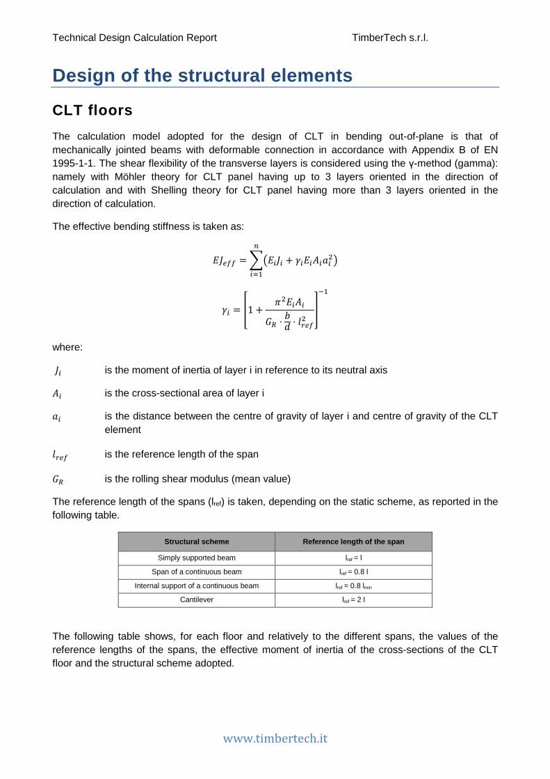
Technical Design Calculation Report TimberTech s.r.l.
www.timbertech.it
Design of the structural elements
CLT floors The calculation model adopted for the design of CLT in bending out-of-plane is that of mechanically jointed beams with deformable connection in accordance with Appendix B of EN 1995-1-1. The shear flexibility of the transverse layers is considered using the γ-method (gamma): namely with Möhler theory for CLT panel having up to 3 layers oriented in the direction of calculation and with Shelling theory for CLT panel having more than 3 layers oriented in the direction of calculation.
The effective bending stiffness is taken as:
𝐸𝐸𝐽𝐽𝑚𝑚𝑒𝑒𝑒𝑒 = ��𝐸𝐸𝑖𝑖𝐽𝐽𝑖𝑖 + 𝛾𝛾𝑖𝑖𝐸𝐸𝑖𝑖𝐴𝐴𝑖𝑖𝑎𝑎𝑖𝑖2�𝑚𝑚
𝑖𝑖=1
𝛾𝛾𝑖𝑖 = �1 +𝜋𝜋2𝐸𝐸𝑖𝑖𝐴𝐴𝑖𝑖
𝐺𝐺𝑅𝑅 ⋅𝑏𝑏𝑜𝑜 ⋅ 𝑜𝑜𝑟𝑟𝑚𝑚𝑒𝑒
2�
−1
where:
𝐽𝐽𝑖𝑖 is the moment of inertia of layer i in reference to its neutral axis
𝐴𝐴𝑖𝑖 is the cross-sectional area of layer i
𝑎𝑎𝑖𝑖 is the distance between the centre of gravity of layer i and centre of gravity of the CLT element
𝑜𝑜𝑟𝑟𝑚𝑚𝑒𝑒 is the reference length of the span
𝐺𝐺𝑅𝑅 is the rolling shear modulus (mean value)
The reference length of the spans (lref) is taken, depending on the static scheme, as reported in the following table.
Structural scheme Reference length of the span
Simply supported beam lref = l
Span of a continuous beam lref = 0.8 l
Internal support of a continuous beam lref = 0.8 lmin
Cantilever lref = 2 l
The following table shows, for each floor and relatively to the different spans, the values of the reference lengths of the spans, the effective moment of inertia of the cross-sections of the CLT floor and the structural scheme adopted.

Technical Design Calculation Report TimberTech s.r.l.
www.timbertech.it
Floor name Calculation width of the strip of floor
[m]
Reference length lref [m]
Jeff [mm4] Structural scheme
Floor 1 1
3.32 3.32
1.841E8 1.841E8
Floor 15 1 2.40
1.651E8
Bending strength
The checks are conducted according to § 6.1.6 of EN 1995-1-1. The following expression shall be satisfied:
𝜎𝜎𝑚𝑚,𝑑𝑑
𝑓𝑓𝑚𝑚,𝑑𝑑≤ 1
being
𝜎𝜎𝑚𝑚,𝑑𝑑 the design bending stress
𝑓𝑓𝑚𝑚,𝑑𝑑 the design bending strength
The following table illustrates the structural schemes and the envelopes of the diagram of the bending moment for the part of each floor where the checks are more severe.
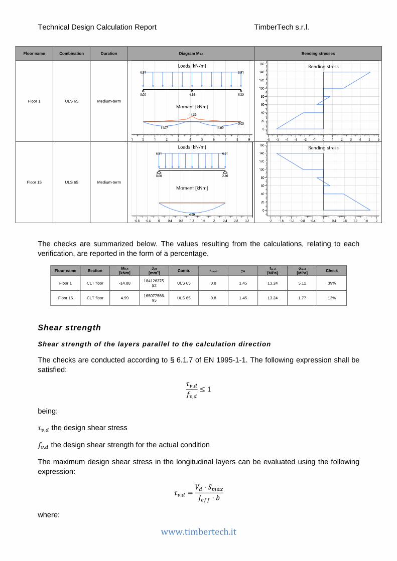
Technical Design Calculation Report TimberTech s.r.l.
www.timbertech.it
Floor name Combination Duration Diagram M3-3 Bending stresses
Floor 1 ULS 65 Medium-term
Floor 15 ULS 65 Medium-term
The checks are summarized below. The values resulting from the calculations, relating to each verification, are reported in the form of a percentage.
Floor name Section M3-3 [kNm]
Jeff [mm4] Comb. kmod γM fm,d
[MPa] σm,d
[MPa] Check
Floor 1 CLT floor -14.88 184126375.52 ULS 65 0.8 1.45 13.24 5.11 39%
Floor 15 CLT floor 4.99 165077566.95 ULS 65 0.8 1.45 13.24 1.77 13%
Shear strength
Shear strength of the layers parallel to the calculation direction
The checks are conducted according to § 6.1.7 of EN 1995-1-1. The following expression shall be satisfied:
𝜏𝜏𝑣𝑣,𝑑𝑑
𝑓𝑓𝑣𝑣,𝑑𝑑≤ 1
being:
𝜏𝜏𝑣𝑣,𝑑𝑑 the design shear stress
𝑓𝑓𝑣𝑣,𝑑𝑑 the design shear strength for the actual condition
The maximum design shear stress in the longitudinal layers can be evaluated using the following expression:
𝜏𝜏𝑣𝑣,𝑑𝑑 =𝑉𝑉𝑑𝑑 ⋅ 𝑆𝑆𝑚𝑚𝑚𝑚𝑥𝑥
𝐽𝐽𝑚𝑚𝑒𝑒𝑒𝑒 ⋅ 𝑏𝑏
where:

Technical Design Calculation Report TimberTech s.r.l.
www.timbertech.it
𝑉𝑉𝑑𝑑 is the total shear force at the location in question
𝑆𝑆𝑚𝑚𝑚𝑚𝑥𝑥 is the first moment of area
𝐽𝐽𝑚𝑚𝑒𝑒𝑒𝑒 is the effective moment of inertia of the CLT element cross section
𝑏𝑏 is the width of the CLT element cross section (𝑘𝑘𝑐𝑐𝑟𝑟 = 1)
Rolling shear strength of the transversal layers
The checks are conducted according to § 6.1.7 of EN 1995-1-1. The following expression shall be satisfied:
𝜏𝜏𝑅𝑅,𝑑𝑑
𝑓𝑓𝑣𝑣,𝑅𝑅,𝑑𝑑≤ 1
being:
𝜏𝜏𝑅𝑅,𝑑𝑑 the design rolling shear stress
𝑓𝑓𝑣𝑣,𝑅𝑅,𝑑𝑑 the design shear strength
The maximum design shear stress in the transversal layers can be evaluated using the following expression:
𝜏𝜏𝑅𝑅,𝑑𝑑 =𝑉𝑉𝑑𝑑 ⋅ 𝑆𝑆𝑅𝑅,𝑚𝑚𝑚𝑚𝑥𝑥
𝐽𝐽𝑚𝑚𝑒𝑒𝑒𝑒 ⋅ 𝑏𝑏
where:
𝑉𝑉𝑑𝑑 is the total shear force at the location in question
𝑆𝑆𝑅𝑅,𝑚𝑚𝑚𝑚𝑥𝑥 is the first moment of area
𝐽𝐽𝑚𝑚𝑒𝑒𝑒𝑒 is the effective moment of inertia of the CLT element cross section
𝑏𝑏 is the width of the CLT element cross section (𝑘𝑘𝑐𝑐𝑟𝑟 = 1)
The following table illustrates the structural schemes and the envelopes of the diagram of the shear force for the part of each floor where the checks are more severe.
Floor name Combination Duration Diagram V2 Shear stresses
Floor 1 ULS 65 Medium-term
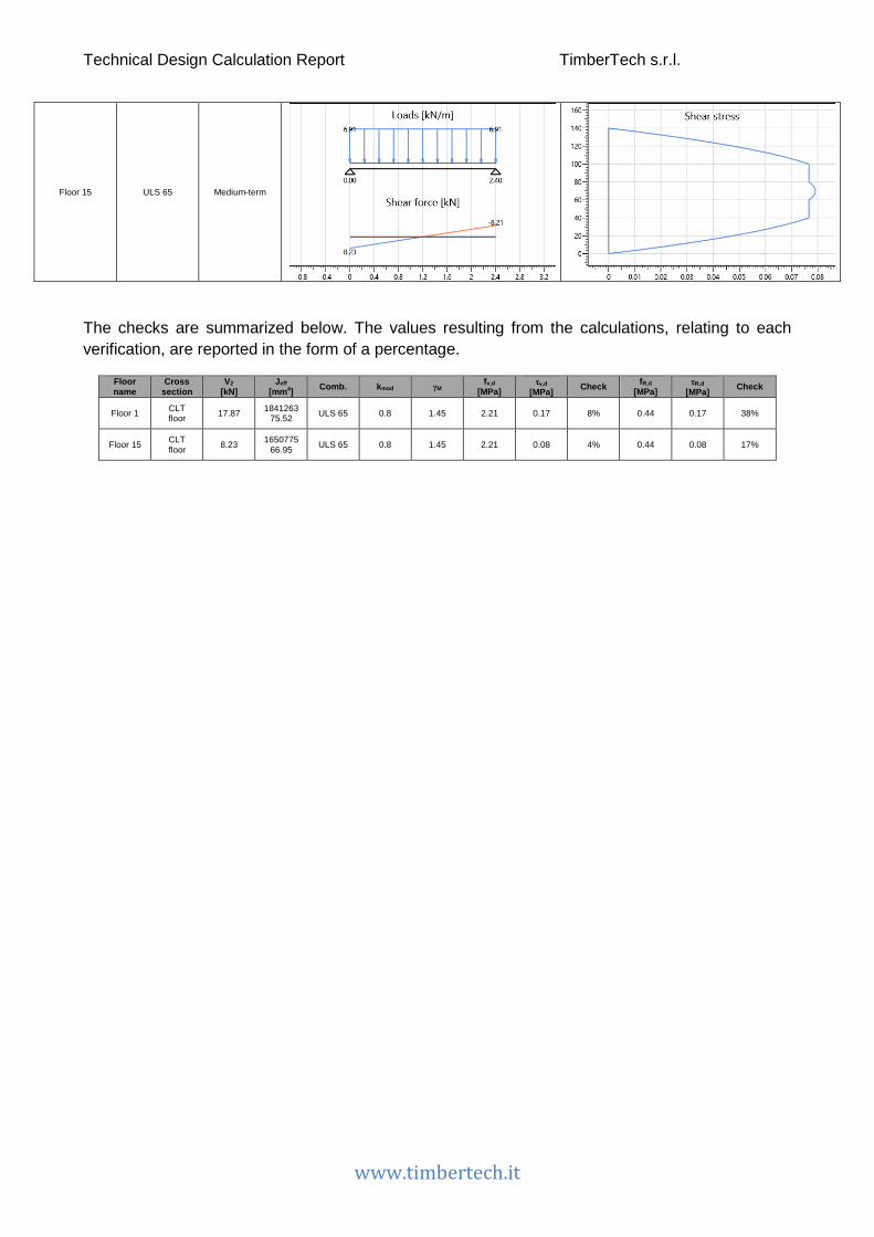
Technical Design Calculation Report TimberTech s.r.l.
www.timbertech.it
Floor 15 ULS 65 Medium-term
The checks are summarized below. The values resulting from the calculations, relating to each verification, are reported in the form of a percentage.
Floor name
Cross section
V2 [kN]
Jeff [mm4] Comb. kmod γM fv,d
[MPa] τv,d
[MPa] Check fR,d [MPa]
τR,d [MPa] Check
Floor 1 CLT floor 17.87 1841263
75.52 ULS 65 0.8 1.45 2.21 0.17 8% 0.44 0.17 38%
Floor 15 CLT floor 8.23 1650775
66.95 ULS 65 0.8 1.45 2.21 0.08 4% 0.44 0.08 17%
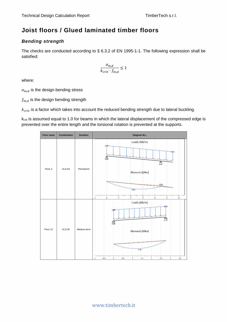
Technical Design Calculation Report TimberTech s.r.l.
www.timbertech.it
Joist floors / Glued laminated timber floors Bending strength
The checks are conducted according to § 6.3.2 of EN 1995-1-1. The following expression shall be satisfied:
𝜎𝜎𝑚𝑚,𝑑𝑑
𝑘𝑘𝑐𝑐𝑟𝑟𝑖𝑖𝑡𝑡 ⋅ 𝑓𝑓𝑚𝑚,𝑑𝑑≤ 1
where:
𝜎𝜎𝑚𝑚,𝑑𝑑 is the design bending stress
𝑓𝑓𝑚𝑚,𝑑𝑑 is the design bending strength
𝑘𝑘𝑐𝑐𝑟𝑟𝑖𝑖𝑡𝑡 is a factor which takes into account the reduced bending strength due to lateral buckling.
kcrit is assumed equal to 1.0 for beams in which the lateral displacement of the compressed edge is prevented over the entire length and the torsional rotation is prevented at the supports.
Floor name Combination Duration Diagram M3-3
Floor 3 ULS 64 Permanent
Floor 12 ULS 65 Medium-term

Technical Design Calculation Report TimberTech s.r.l.
www.timbertech.it
Floor 13 ULS 65 Medium-term
Floor 14 ULS 64 Permanent
The checks are summarized below. The values resulting from the calculations, relating to each verification, are reported in the form of a percentage.
Floor name Section M3-3 max [kNm]
W [mm3] kcrit Comb. kmod γM fm,d
[MPa] σm,d
[MPa] Check
Floor 3 Joist floor 160x240 4.83 1536000 1.00 ULS 64 0.6 1.45 9.93 3.15 32%
Floor 12 Joist floor 160x240 3.36 1536000 1.00 ULS 65 0.8 1.45 13.24 2.19 17%
Floor 13 Joist floor 160x240 3.36 1536000 1.00 ULS 65 0.8 1.45 13.24 2.19 17%
Floor 14 Joist floor 160x240 4.86 1536000 1.00 ULS 64 0.6 1.45 9.93 3.17 32%

Technical Design Calculation Report TimberTech s.r.l.
www.timbertech.it
Shear strength
The checks are conducted according to § 6.1.7 of EN 1995-1-1. The following expression shall be satisfied:
𝜏𝜏𝑑𝑑𝑓𝑓𝑣𝑣,𝑑𝑑
≤ 1
where:
𝜏𝜏𝑑𝑑 is the design shear stress
𝑓𝑓𝑣𝑣,𝑑𝑑 is the design shear strength for the actual condition
For the verification of shear resistance of members in bending, the influence of cracks should be
taken into account using an effective width of the member given as:
𝑏𝑏𝑚𝑚𝑒𝑒 = 𝑘𝑘𝑐𝑐𝑟𝑟 ⋅ 𝑏𝑏
where b is the width of the relevant section of the member.
The following value of kcr are used
kcr = 0.67 for solid timber
kcr = 0.67 for glued laminated timber
The maximum design shear stress in a rectangular cross section can be evaluated using the following expression:
𝜏𝜏𝑑𝑑 =32⋅
𝑉𝑉𝑑𝑑𝑘𝑘𝑐𝑐𝑟𝑟 ⋅ 𝐴𝐴
where A is the area of a joist cross section.
The following table illustrates the structural schemes and the envelopes of the shear force diagram for the joist of each floor where the checks are more severe.
Floor name Combination Duration Diagram V2
Floor 3 ULS 64 Permanent

Technical Design Calculation Report TimberTech s.r.l.
www.timbertech.it
Floor 12 ULS 65 Medium-term
Floor 13 ULS 65 Medium-term
Floor 14 ULS 64 Permanent
The checks are summarized below. The values resulting from the calculations, relating to each verification, are reported in the form of a percentage.
Floor name Section V2 max [kN]
Area [mm2] kcr Comb. kmod γM fv,d
[MPa] τ2,d
[MPa] Check
Floor 3 Joist floor 160x240 4.54 38400 0.67 ULS 64 0.6 1.45 1.45 0.26 18%
Floor 12 Joist floor 160x240 4.84 38400 0.67 ULS 65 0.8 1.45 1.93 0.28 15%
Floor 13 Joist floor 160x240 4.84 38400 0.67 ULS 65 0.8 1.45 1.93 0.28 15%
Floor 14 Joist floor 160x240 4.57 38400 0.67 ULS 64 0.6 1.45 1.45 0.27 18%

Technical Design Calculation Report TimberTech s.r.l.
www.timbertech.it
Floors deflections (SLS)
The deflection checks are carried out according to § 2.2.3 of EN 1995-1-1.
The net deflection below a straight line between the supports, wnet,fin, is taken as:
𝑑𝑑𝑚𝑚𝑚𝑚𝑡𝑡,𝑒𝑒𝑖𝑖𝑚𝑚 = 𝑑𝑑𝑖𝑖𝑚𝑚𝑠𝑠𝑡𝑡 + 𝑑𝑑𝑐𝑐𝑟𝑟𝑚𝑚𝑚𝑚𝑖𝑖 − 𝑑𝑑𝑐𝑐 = 𝑑𝑑𝑒𝑒𝑖𝑖𝑚𝑚 − 𝑑𝑑𝑐𝑐
where:
𝑑𝑑𝑚𝑚𝑚𝑚𝑡𝑡,𝑒𝑒𝑖𝑖𝑚𝑚 is the net final deflection
𝑑𝑑𝑖𝑖𝑚𝑚𝑠𝑠𝑡𝑡 is the instantaneous deflection
𝑑𝑑𝑐𝑐𝑟𝑟𝑚𝑚𝑚𝑚𝑖𝑖 is the creep deflection
𝑑𝑑𝑐𝑐 is the precamber (if applied)
𝑑𝑑𝑒𝑒𝑖𝑖𝑚𝑚 is the final deflection
The limiting values for deflections of floors are assumed as shown in the following table.
winst wnet,fin
Beam on two supports l/300 l/250
Cantilevering beams l/150 l/125
Instantaneous deflection
The instantaneous deflection winst is calculated for the characteristic (rare) combination of actions.
The following table shows the deformation of each floor (relative to the element in which the deformation checks are more severe).

Technical Design Calculation Report TimberTech s.r.l.
www.timbertech.it
Floor name Combination Instantaneous deflection
Floor 1 SLS characteristic 2
Floor 3 SLS characteristic 14
Floor 12 SLS characteristic 2
Floor 13 SLS characteristic 2
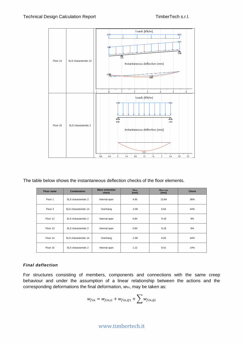
Technical Design Calculation Report TimberTech s.r.l.
www.timbertech.it
Floor 14 SLS characteristic 14
Floor 15 SLS characteristic 2
The table below shows the instantaneous deflection checks of the floor elements.
Floor name Combination More restrictive check
winst [mm]
winst limit [mm] Check
Floor 1 SLS characteristic 2 Internal span 4.95 13.84 36%
Floor 3 SLS characteristic 14 Overhang -2.90 6.64 44%
Floor 12 SLS characteristic 2 Internal span 0.84 9.18 9%
Floor 13 SLS characteristic 2 Internal span 0.84 9.18 9%
Floor 14 SLS characteristic 14 Overhang -2.90 6.65 44%
Floor 15 SLS characteristic 2 Internal span 1.12 8.01 14%
Final deflection
For structures consisting of members, components and connections with the same creep behaviour and under the assumption of a linear relationship between the actions and the corresponding deformations the final deformation, wfin, may be taken as:
𝑑𝑑𝑒𝑒𝑖𝑖𝑚𝑚 = 𝑑𝑑𝑒𝑒𝑖𝑖𝑚𝑚,𝐺𝐺 + 𝑑𝑑𝑒𝑒𝑖𝑖𝑚𝑚,𝑄𝑄1 + �𝑑𝑑𝑒𝑒𝑖𝑖𝑚𝑚,𝑄𝑄𝑖𝑖
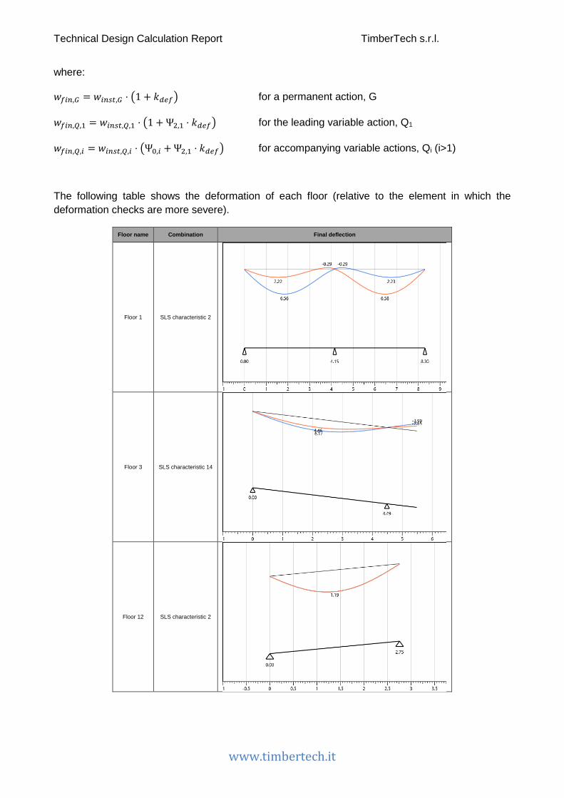
Technical Design Calculation Report TimberTech s.r.l.
www.timbertech.it
where:
𝑑𝑑𝑒𝑒𝑖𝑖𝑚𝑚,𝐺𝐺 = 𝑑𝑑𝑖𝑖𝑚𝑚𝑠𝑠𝑡𝑡,𝐺𝐺 ⋅ �1 + 𝑘𝑘𝑑𝑑𝑚𝑚𝑒𝑒� for a permanent action, G
𝑑𝑑𝑒𝑒𝑖𝑖𝑚𝑚,𝑄𝑄,1 = 𝑑𝑑𝑖𝑖𝑚𝑚𝑠𝑠𝑡𝑡,𝑄𝑄,1 ⋅ �1 + Ψ2,1 ⋅ 𝑘𝑘𝑑𝑑𝑚𝑚𝑒𝑒� for the leading variable action, Q1
𝑑𝑑𝑒𝑒𝑖𝑖𝑚𝑚,𝑄𝑄,𝑖𝑖 = 𝑑𝑑𝑖𝑖𝑚𝑚𝑠𝑠𝑡𝑡,𝑄𝑄,𝑖𝑖 ⋅ �Ψ0,𝑖𝑖 +Ψ2,1 ⋅ 𝑘𝑘𝑑𝑑𝑚𝑚𝑒𝑒� for accompanying variable actions, Qi (i>1)
The following table shows the deformation of each floor (relative to the element in which the deformation checks are more severe).
Floor name Combination Final deflection
Floor 1 SLS characteristic 2
Floor 3 SLS characteristic 14
Floor 12 SLS characteristic 2

Technical Design Calculation Report TimberTech s.r.l.
www.timbertech.it
Floor 13 SLS characteristic 2
Floor 14 SLS characteristic 14
Floor 15 SLS characteristic 2
The table below shows the final deflection checks of the floor elements.
Floor name Combination More restrictive check
wfin [mm]
wfin limit [mm] Check
Floor 1 SLS characteristic 2 Internal span 6.84 16.61 41%
Floor 3 SLS characteristic 14 Overhang -3.99 7.97 50%
Floor 12 SLS characteristic 2 Internal span 1.19 11.02 11%
Floor 13 SLS characteristic 2 Internal span 1.19 11.02 11%
Floor 14 SLS characteristic 14 Overhang -3.98 7.98 50%
Floor 15 SLS characteristic 2 Internal span 1.59 9.61 17%

Technical Design Calculation Report TimberTech s.r.l.
www.timbertech.it
Beams Bending strength
The checks are conducted according to § 6.3.2 of EN 1995-1-1. The following expression shall be satisfied:
𝜎𝜎𝑚𝑚,𝑑𝑑
𝑘𝑘𝑐𝑐𝑟𝑟𝑖𝑖𝑡𝑡 ⋅ 𝑓𝑓𝑚𝑚,𝑑𝑑≤ 1
where:
𝜎𝜎𝑚𝑚,𝑑𝑑 is the design bending stress
𝑓𝑓𝑚𝑚,𝑑𝑑 is the design bending strength
𝑘𝑘𝑐𝑐𝑟𝑟𝑖𝑖𝑡𝑡 is a factor which takes into account the reduced bending strength due to lateral buckling.
kcrit is assumed equal to 1.0 for beams in which the lateral displacement of the compressed edge is prevented over the entire length and the torsional rotation is prevented at the supports.
Beam name Combination Duration Diagram M3-3
Beam 2 ULS 64 Permanent
Beam 3 ULS 64 Permanent

Technical Design Calculation Report TimberTech s.r.l.
www.timbertech.it
Beam 4 ULS 64 Permanent
Beam 5 ULS 65 Medium-term
Beam 6 ULS 65 Medium-term
Beam 10 ULS 65 Medium-term

Technical Design Calculation Report TimberTech s.r.l.
www.timbertech.it
Beam 11 ULS 64 Permanent
Beam 16 ULS 64 Permanent
Beam 17 ULS 64 Permanent
Beam 18 ULS 64 Permanent

Technical Design Calculation Report TimberTech s.r.l.
www.timbertech.it
Beam 19 ULS 64 Permanent
Beam 20 ULS 65 Medium-term
Beam 21 ULS 65 Medium-term
Beam 37 ULS 43 Permanent

Technical Design Calculation Report TimberTech s.r.l.
www.timbertech.it
Beam 42 ULS 65 Medium-term
Beam 47 ULS 65 Medium-term
Beam 48 ULS 64 Permanent
Beam 49 ULS 64 Permanent

Technical Design Calculation Report TimberTech s.r.l.
www.timbertech.it
Beam 50 ULS 65 Medium-term
Beam 51 ULS 65 Medium-term
Beam 52 ULS 43 Permanent
Beam 53 ULS 65 Medium-term
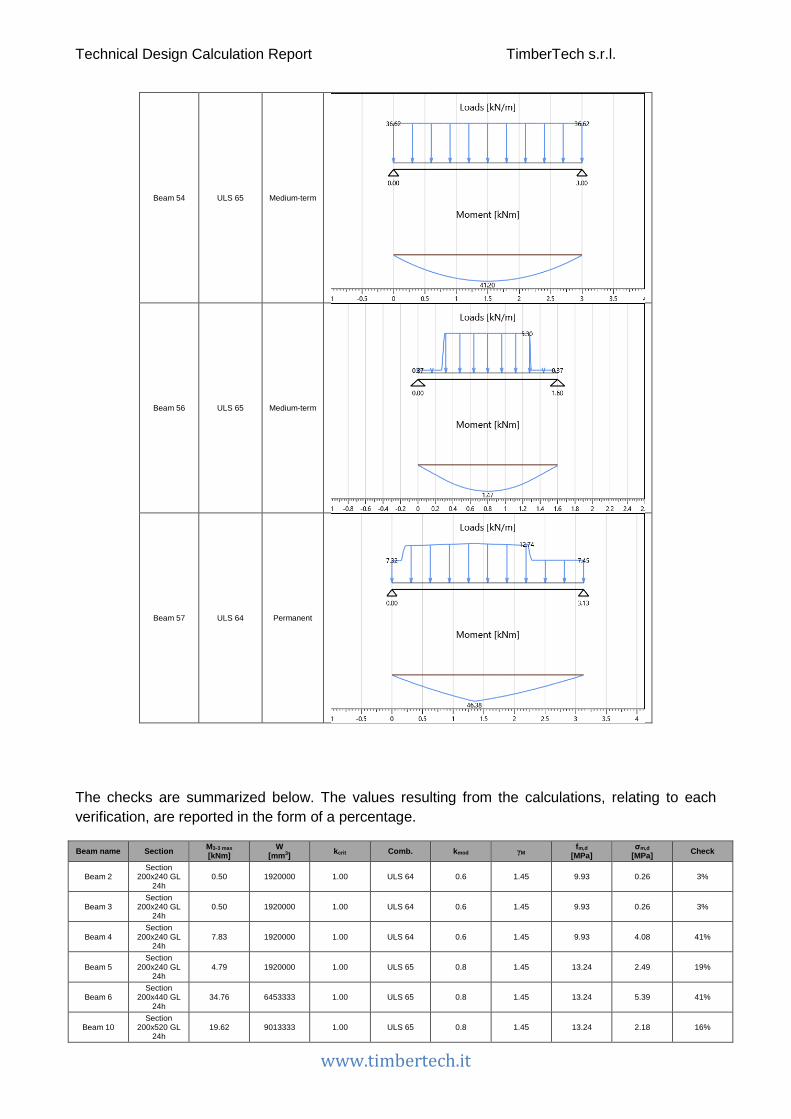
Technical Design Calculation Report TimberTech s.r.l.
www.timbertech.it
Beam 54 ULS 65 Medium-term
Beam 56 ULS 65 Medium-term
Beam 57 ULS 64 Permanent
The checks are summarized below. The values resulting from the calculations, relating to each verification, are reported in the form of a percentage.
Beam name Section M3-3 max [kNm]
W [mm3] kcrit Comb. kmod γM fm,d
[MPa] σm,d
[MPa] Check
Beam 2 Section
200x240 GL 24h
0.50 1920000 1.00 ULS 64 0.6 1.45 9.93 0.26 3%
Beam 3 Section
200x240 GL 24h
0.50 1920000 1.00 ULS 64 0.6 1.45 9.93 0.26 3%
Beam 4 Section
200x240 GL 24h
7.83 1920000 1.00 ULS 64 0.6 1.45 9.93 4.08 41%
Beam 5 Section
200x240 GL 24h
4.79 1920000 1.00 ULS 65 0.8 1.45 13.24 2.49 19%
Beam 6 Section
200x440 GL 24h
34.76 6453333 1.00 ULS 65 0.8 1.45 13.24 5.39 41%
Beam 10 Section
200x520 GL 24h
19.62 9013333 1.00 ULS 65 0.8 1.45 13.24 2.18 16%

Technical Design Calculation Report TimberTech s.r.l.
www.timbertech.it
Beam 11 Section
200x240 GL 24h
11.24 1920000 1.00 ULS 64 0.6 1.45 9.93 5.85 59%
Beam 16 Section
200x240 GL 24h
6.07 1920000 1.00 ULS 64 0.6 1.45 9.93 3.16 32%
Beam 17 Section
200x240 GL 24h
8.51 1920000 1.00 ULS 64 0.6 1.45 9.93 4.43 45%
Beam 18 Section
200x440 GL 24h
56.84 6453333 1.00 ULS 64 0.6 1.45 9.93 8.81 89%
Beam 19 Section
200x240 GL 24h
6.07 1920000 1.00 ULS 64 0.6 1.45 9.93 3.16 32%
Beam 20 Section
200x240 GL 24h
4.66 1920000 1.00 ULS 65 0.8 1.45 13.24 2.43 18%
Beam 21 Section
200x240 GL 24h
4.68 1920000 1.00 ULS 65 0.8 1.45 13.24 2.44 18%
Beam 37 Section
200x240 GL 24h
1.17 1920000 1.00 ULS 43 0.6 1.45 9.93 0.61 6%
Beam 42 Section
200x240 GL 24h
4.71 1920000 1.00 ULS 65 0.8 1.45 13.24 2.45 19%
Beam 47 Section
200x440 GL 24h
58.51 6453333 1.00 ULS 65 0.8 1.45 13.24 9.07 68%
Beam 48 Section
200x240 GL 24h
10.12 1920000 1.00 ULS 64 0.6 1.45 9.93 5.27 53%
Beam 49 Section
200x240 GL 24h
10.11 1920000 1.00 ULS 64 0.6 1.45 9.93 5.27 53%
Beam 50 Section
200x240 GL 24h
2.72 1920000 1.00 ULS 65 0.8 1.45 13.24 1.42 11%
Beam 51 Section
200x520 GL 24h
82.03 9013333 1.00 ULS 65 0.8 1.45 13.24 9.10 69%
Beam 52 Section
200x240 GL 24h
0.15 1920000 1.00 ULS 43 0.6 1.45 9.93 0.08 1%
Beam 53 Section
200x240 GL 24h
10.77 1920000 1.00 ULS 65 0.8 1.45 13.24 5.61 42%
Beam 54 Section
200x440 GL 24h
41.20 6453333 1.00 ULS 65 0.8 1.45 13.24 6.38 48%
Beam 56 Section
200x240 GL 24h
1.47 1920000 1.00 ULS 65 0.8 1.45 13.24 0.77 6%
Beam 57 Section
200x440 GL 24h
46.38 6453333 1.00 ULS 64 0.6 1.45 9.93 7.19 72%
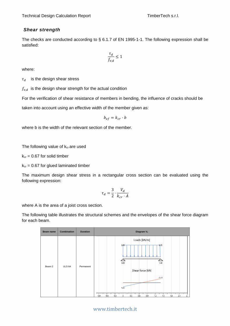
Technical Design Calculation Report TimberTech s.r.l.
www.timbertech.it
Shear strength
The checks are conducted according to § 6.1.7 of EN 1995-1-1. The following expression shall be satisfied:
𝜏𝜏𝑑𝑑𝑓𝑓𝑣𝑣,𝑑𝑑
≤ 1
where:
𝜏𝜏𝑑𝑑 is the design shear stress
𝑓𝑓𝑣𝑣,𝑑𝑑 is the design shear strength for the actual condition
For the verification of shear resistance of members in bending, the influence of cracks should be
taken into account using an effective width of the member given as:
𝑏𝑏𝑚𝑚𝑒𝑒 = 𝑘𝑘𝑐𝑐𝑟𝑟 ⋅ 𝑏𝑏
where b is the width of the relevant section of the member.
The following value of kcr are used
kcr = 0.67 for solid timber
kcr = 0.67 for glued laminated timber
The maximum design shear stress in a rectangular cross section can be evaluated using the following expression:
𝜏𝜏𝑑𝑑 =32⋅
𝑉𝑉𝑑𝑑𝑘𝑘𝑐𝑐𝑟𝑟 ⋅ 𝐴𝐴
where A is the area of a joist cross section.
The following table illustrates the structural schemes and the envelopes of the shear force diagram for each beam.
Beam name Combination Duration Diagram V2
Beam 2 ULS 64 Permanent

Technical Design Calculation Report TimberTech s.r.l.
www.timbertech.it
Beam 3 ULS 64 Permanent
Beam 4 ULS 64 Permanent
Beam 5 ULS 65 Medium-term
Beam 6 ULS 65 Medium-term
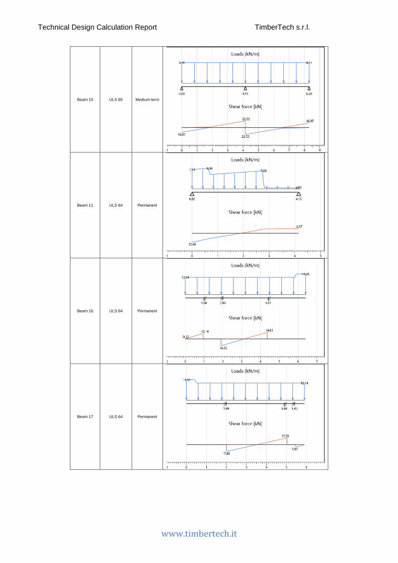
Technical Design Calculation Report TimberTech s.r.l.
www.timbertech.it
Beam 10 ULS 65 Medium-term
Beam 11 ULS 64 Permanent
Beam 16 ULS 64 Permanent
Beam 17 ULS 64 Permanent

Technical Design Calculation Report TimberTech s.r.l.
www.timbertech.it
Beam 18 ULS 64 Permanent
Beam 19 ULS 64 Permanent
Beam 20 ULS 65 Medium-term
Beam 21 ULS 65 Medium-term
Technical Design Calculation Report TimberTech s.r.l.
www.timbertech.it
Beam 37 ULS 43 Permanent
Beam 42 ULS 65 Medium-term
Beam 47 ULS 65 Medium-term
Beam 48 ULS 70 Medium-term

Technical Design Calculation Report TimberTech s.r.l.
www.timbertech.it
Beam 49 ULS 70 Medium-term
Beam 50 ULS 65 Medium-term
Beam 51 ULS 65 Medium-term
Beam 52 ULS 43 Permanent
Technical Design Calculation Report TimberTech s.r.l.
www.timbertech.it
Beam 53 ULS 65 Medium-term
Beam 54 ULS 65 Medium-term
Beam 56 ULS 65 Medium-term
Beam 57 ULS 64 Permanent

Technical Design Calculation Report TimberTech s.r.l.
www.timbertech.it
The checks are summarized below. The values resulting from the calculations, relating to each verification, are reported in the form of a percentage.
Beam name Section V2 max [kN]
Area [mm2] kcr Comb. kmod γM fv,d
[MPa] τ2,d
[MPa] Check
Beam 2 Section
200x240 GL 24h
1.42 48000 0.67 ULS 64 0.6 1.45 1.45 0.07 5%
Beam 3 Section
200x240 GL 24h
1.42 48000 0.67 ULS 64 0.6 1.45 1.45 0.07 5%
Beam 4 Section
200x240 GL 24h
20.36 48000 0.67 ULS 64 0.6 1.45 1.45 0.95 66%
Beam 5 Section
200x240 GL 24h
13.60 48000 0.67 ULS 65 0.8 1.45 1.93 0.63 33%
Beam 6 Section
200x440 GL 24h
41.42 88000 0.67 ULS 65 0.8 1.45 1.93 1.05 55%
Beam 10 Section
200x520 GL 24h
23.55 104000 0.67 ULS 65 0.8 1.45 1.93 0.51 26%
Beam 11 Section
200x240 GL 24h
12.46 48000 0.67 ULS 64 0.6 1.45 1.45 0.58 40%
Beam 16 Section
200x240 GL 24h
14.61 48000 0.67 ULS 64 0.6 1.45 1.45 0.68 47%
Beam 17 Section
200x240 GL 24h
17.59 48000 0.67 ULS 64 0.6 1.45 1.45 0.82 57%
Beam 18 Section
200x440 GL 24h
52.68 88000 0.67 ULS 64 0.6 1.45 1.45 1.34 93%
Beam 19 Section
200x240 GL 24h
12.01 48000 0.67 ULS 64 0.6 1.45 1.45 0.56 39%
Beam 20 Section
200x240 GL 24h
9.57 48000 0.67 ULS 65 0.8 1.45 1.93 0.45 23%
Beam 21 Section
200x240 GL 24h
9.61 48000 0.67 ULS 65 0.8 1.45 1.93 0.45 23%
Beam 37 Section
200x240 GL 24h
0.93 48000 0.67 ULS 43 0.6 1.45 1.45 0.04 3%
Beam 42 Section
200x240 GL 24h
9.36 48000 0.67 ULS 65 0.8 1.45 1.93 0.44 23%
Beam 47 Section
200x440 GL 24h
48.36 88000 0.67 ULS 65 0.8 1.45 1.93 1.23 64%
Beam 48 Section
200x240 GL 24h
16.02 48000 0.67 ULS 70 0.8 1.45 1.93 0.75 39%
Beam 49 Section
200x240 GL 24h
15.98 48000 0.67 ULS 70 0.8 1.45 1.93 0.75 39%
Beam 50 Section
200x240 GL 24h
8.22 48000 0.67 ULS 65 0.8 1.45 1.93 0.38 20%
Beam 51 Section
200x520 GL 24h
59.25 104000 0.67 ULS 65 0.8 1.45 1.93 1.28 66%
Beam 52 Section
200x240 GL 24h
0.33 48000 0.67 ULS 43 0.6 1.45 1.45 0.02 1%
Beam 53 Section
200x240 GL 24h
20.20 48000 0.67 ULS 65 0.8 1.45 1.93 0.94 49%
Beam 54 Section
200x440 GL 24h
54.56 88000 0.67 ULS 65 0.8 1.45 1.93 1.39 72%
Beam 56 Section
200x240 GL 24h
2.76 48000 0.67 ULS 65 0.8 1.45 1.93 0.13 7%
Beam 57 Section
200x440 GL 24h
41.82 88000 0.67 ULS 64 0.6 1.45 1.45 1.06 73%

Technical Design Calculation Report TimberTech s.r.l.
www.timbertech.it
Beams deflections (SLS)
The deflection checks are carried out according to § 2.2.3 of EN 1995-1-1.
The net deflection below a straight line between the supports, wnet,fin, is taken as:
𝑑𝑑𝑚𝑚𝑚𝑚𝑡𝑡,𝑒𝑒𝑖𝑖𝑚𝑚 = 𝑑𝑑𝑖𝑖𝑚𝑚𝑠𝑠𝑡𝑡 + 𝑑𝑑𝑐𝑐𝑟𝑟𝑚𝑚𝑚𝑚𝑖𝑖 − 𝑑𝑑𝑐𝑐 = 𝑑𝑑𝑒𝑒𝑖𝑖𝑚𝑚 − 𝑑𝑑𝑐𝑐
where:
𝑑𝑑𝑚𝑚𝑚𝑚𝑡𝑡,𝑒𝑒𝑖𝑖𝑚𝑚 is the net final deflection
𝑑𝑑𝑖𝑖𝑚𝑚𝑠𝑠𝑡𝑡 is the instantaneous deflection
𝑑𝑑𝑐𝑐𝑟𝑟𝑚𝑚𝑚𝑚𝑖𝑖 is the creep deflection
𝑑𝑑𝑐𝑐 is the precamber (if applied)
𝑑𝑑𝑒𝑒𝑖𝑖𝑚𝑚 is the final deflection
The limiting values for deflections of beams are assumed as shown in the following table.
winst wnet,fin
Beam on two supports l/300 l/250
Cantilevering beams l/150 l/125

Technical Design Calculation Report TimberTech s.r.l.
www.timbertech.it
Instantaneous deflection
The instantaneous deflection winst is calculated for the characteristic (rare) combination of actions.
The following table shows the deformation of each beam.
Beam name Combination Instantaneous deflection
Beam 2 SLS characteristic 1
Beam 3 SLS characteristic 1
Beam 4 SLS characteristic 15

Technical Design Calculation Report TimberTech s.r.l.
www.timbertech.it
Beam 5 SLS characteristic 2
Beam 6 SLS characteristic 3
Beam 10 SLS characteristic 2
Beam 11 SLS characteristic 15
Technical Design Calculation Report TimberTech s.r.l.
www.timbertech.it
Beam 16 SLS characteristic 14
Beam 17 SLS characteristic 14
Beam 18 SLS characteristic 14
Beam 19 SLS characteristic 14

Technical Design Calculation Report TimberTech s.r.l.
www.timbertech.it
Beam 20 SLS characteristic 2
Beam 21 SLS characteristic 2
Beam 37 SLS characteristic 1
Beam 42 SLS characteristic 2

Technical Design Calculation Report TimberTech s.r.l.
www.timbertech.it
Beam 47 SLS characteristic 2
Beam 48 SLS characteristic 15
Beam 49 SLS characteristic 15
Beam 50 SLS characteristic 2
Technical Design Calculation Report TimberTech s.r.l.
www.timbertech.it
Beam 51 SLS characteristic 3
Beam 52 SLS characteristic 1
Beam 53 SLS characteristic 2
Beam 54 SLS characteristic 2

Technical Design Calculation Report TimberTech s.r.l.
www.timbertech.it
Beam 56 SLS characteristic 2
Beam 57 SLS characteristic 15
The table below shows the instantaneous deflection checks of the beams.
Beam name Combination More restrictive check
winst [mm]
winst limit [mm] Check
Beam 2 SLS characteristic 1 Internal span 0.03 4.67 1%
Beam 3 SLS characteristic 1 Internal span 0.03 4.67 1%
Beam 4 SLS characteristic 15 Internal span 0.75 5.33 14%
Beam 5 SLS characteristic 2 Internal span 0.33 5.33 6%
Beam 6 SLS characteristic 3 Internal span 1.82 13.83 13%
Beam 10 SLS characteristic 2 Internal span 0.47 13.83 3%
Beam 11 SLS characteristic 15 Internal span 5.33 13.83 39%
Beam 16 SLS characteristic 14 Overhang 0.57 6.67 9%
Beam 17 SLS characteristic 14 Internal span 0.84 9.67 9%
Beam 18 SLS characteristic 14 Overhang -1.47 3.33 44%
Beam 19 SLS characteristic 14 Overhang 0.57 6.67 9%
Beam 20 SLS characteristic 2 Overhang 0.72 6.67 11%
Beam 21 SLS characteristic 2 Overhang 0.73 6.67 11%
Beam 37 SLS characteristic 1 Internal span 0.88 16.67 5%

Technical Design Calculation Report TimberTech s.r.l.
www.timbertech.it
Beam 42 SLS characteristic 2 Internal span 0.42 8.33 5%
Beam 47 SLS characteristic 2 Overhang -4.07 6.67 61%
Beam 48 SLS characteristic 15 Internal span 6.12 13.09 47%
Beam 49 SLS characteristic 15 Internal span 6.11 13.09 47%
Beam 50 SLS characteristic 2 Internal span 0.14 4.67 3%
Beam 51 SLS characteristic 3 Internal span 5.26 16.67 32%
Beam 52 SLS characteristic 1 Internal span 0.01 6.00 0%
Beam 53 SLS characteristic 2 Internal span 0.80 5.66 14%
Beam 54 SLS characteristic 2 Internal span 1.61 10.00 16%
Beam 56 SLS characteristic 2 Internal span 0.10 5.33 2%
Beam 57 SLS characteristic 15 Internal span 2.33 10.43 22%
Final deflection
For structures consisting of members, components and connections with the same creep behaviour and under the assumption of a linear relationship between the actions and the corresponding deformations the final deformation, wfin, may be taken as:
𝑑𝑑𝑒𝑒𝑖𝑖𝑚𝑚 = 𝑑𝑑𝑒𝑒𝑖𝑖𝑚𝑚,𝐺𝐺 + 𝑑𝑑𝑒𝑒𝑖𝑖𝑚𝑚,𝑄𝑄1 + �𝑑𝑑𝑒𝑒𝑖𝑖𝑚𝑚,𝑄𝑄𝑖𝑖
where:
𝑑𝑑𝑒𝑒𝑖𝑖𝑚𝑚,𝐺𝐺 = 𝑑𝑑𝑖𝑖𝑚𝑚𝑠𝑠𝑡𝑡,𝐺𝐺 ⋅ �1 + 𝑘𝑘𝑑𝑑𝑚𝑚𝑒𝑒� for a permanent action, G
𝑑𝑑𝑒𝑒𝑖𝑖𝑚𝑚,𝑄𝑄,1 = 𝑑𝑑𝑖𝑖𝑚𝑚𝑠𝑠𝑡𝑡,𝑄𝑄,1 ⋅ �1 + Ψ2,1 ⋅ 𝑘𝑘𝑑𝑑𝑚𝑚𝑒𝑒� for the leading variable action, Q1
𝑑𝑑𝑒𝑒𝑖𝑖𝑚𝑚,𝑄𝑄,𝑖𝑖 = 𝑑𝑑𝑖𝑖𝑚𝑚𝑠𝑠𝑡𝑡,𝑄𝑄,𝑖𝑖 ⋅ �Ψ0,𝑖𝑖 +Ψ2,1 ⋅ 𝑘𝑘𝑑𝑑𝑚𝑚𝑒𝑒� for accompanying variable actions, Qi (i>1)

Technical Design Calculation Report TimberTech s.r.l.
www.timbertech.it
The following table shows the deformation of each floor (relative to the element in which the deformation checks are more severe).
Beam name Combination Final deflection
Beam 2 SLS characteristic 1
Beam 3 SLS characteristic 1
Beam 4 SLS characteristic 15
Beam 5 SLS characteristic 2

Technical Design Calculation Report TimberTech s.r.l.
www.timbertech.it
Beam 6 SLS characteristic 3
Beam 10 SLS characteristic 2
Beam 11 SLS characteristic 15
Beam 16 SLS characteristic 14

Technical Design Calculation Report TimberTech s.r.l.
www.timbertech.it
Beam 17 SLS characteristic 14
Beam 18 SLS characteristic 14
Beam 19 SLS characteristic 14
Beam 20 SLS characteristic 2
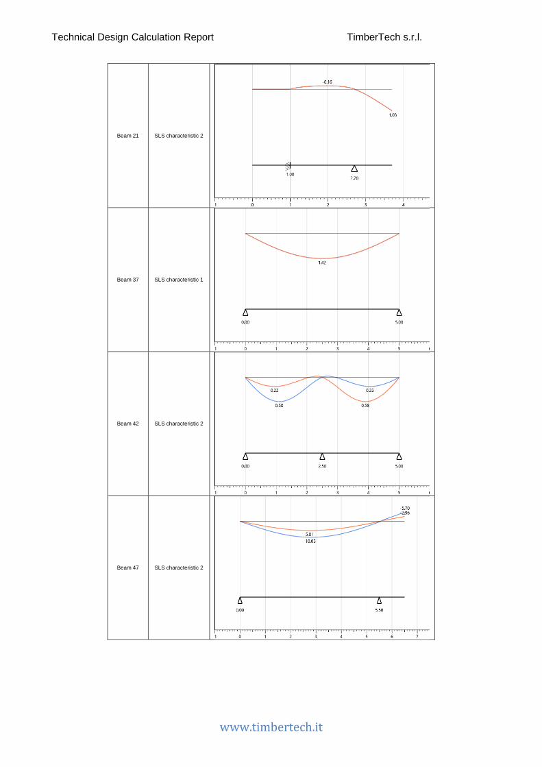
Technical Design Calculation Report TimberTech s.r.l.
www.timbertech.it
Beam 21 SLS characteristic 2
Beam 37 SLS characteristic 1
Beam 42 SLS characteristic 2
Beam 47 SLS characteristic 2
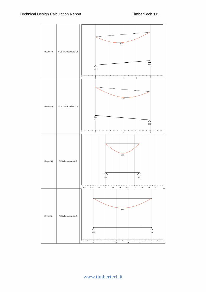
Technical Design Calculation Report TimberTech s.r.l.
www.timbertech.it
Beam 48 SLS characteristic 15
Beam 49 SLS characteristic 15
Beam 50 SLS characteristic 2
Beam 51 SLS characteristic 3

Technical Design Calculation Report TimberTech s.r.l.
www.timbertech.it
Beam 52 SLS characteristic 1
Beam 53 SLS characteristic 2
Beam 54 SLS characteristic 2
Beam 56 SLS characteristic 2
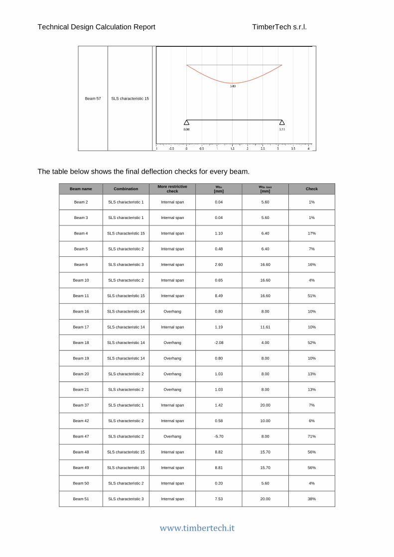
Technical Design Calculation Report TimberTech s.r.l.
www.timbertech.it
Beam 57 SLS characteristic 15
The table below shows the final deflection checks for every beam.
Beam name Combination More restrictive check
wfin [mm]
wfin limit [mm] Check
Beam 2 SLS characteristic 1 Internal span 0.04 5.60 1%
Beam 3 SLS characteristic 1 Internal span 0.04 5.60 1%
Beam 4 SLS characteristic 15 Internal span 1.10 6.40 17%
Beam 5 SLS characteristic 2 Internal span 0.48 6.40 7%
Beam 6 SLS characteristic 3 Internal span 2.60 16.60 16%
Beam 10 SLS characteristic 2 Internal span 0.65 16.60 4%
Beam 11 SLS characteristic 15 Internal span 8.49 16.60 51%
Beam 16 SLS characteristic 14 Overhang 0.80 8.00 10%
Beam 17 SLS characteristic 14 Internal span 1.19 11.61 10%
Beam 18 SLS characteristic 14 Overhang -2.08 4.00 52%
Beam 19 SLS characteristic 14 Overhang 0.80 8.00 10%
Beam 20 SLS characteristic 2 Overhang 1.03 8.00 13%
Beam 21 SLS characteristic 2 Overhang 1.03 8.00 13%
Beam 37 SLS characteristic 1 Internal span 1.42 20.00 7%
Beam 42 SLS characteristic 2 Internal span 0.58 10.00 6%
Beam 47 SLS characteristic 2 Overhang -5.70 8.00 71%
Beam 48 SLS characteristic 15 Internal span 8.82 15.70 56%
Beam 49 SLS characteristic 15 Internal span 8.81 15.70 56%
Beam 50 SLS characteristic 2 Internal span 0.20 5.60 4%
Beam 51 SLS characteristic 3 Internal span 7.53 20.00 38%

Technical Design Calculation Report TimberTech s.r.l.
www.timbertech.it
Beam 52 SLS characteristic 1 Internal span 0.02 7.20 0%
Beam 53 SLS characteristic 2 Internal span 1.13 6.79 17%
Beam 54 SLS characteristic 2 Internal span 2.30 12.00 19%
Beam 56 SLS characteristic 2 Internal span 0.14 6.40 2%
Beam 57 SLS characteristic 15 Internal span 3.40 12.52 27%
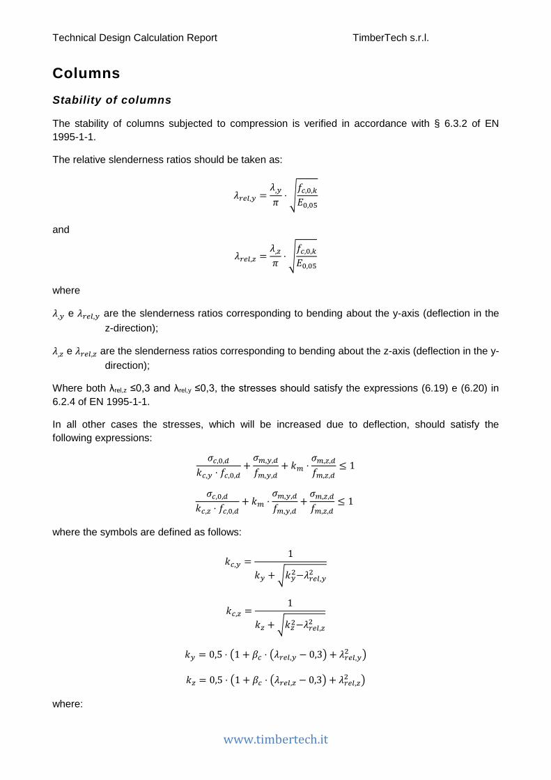
Technical Design Calculation Report TimberTech s.r.l.
www.timbertech.it
Columns Stability of columns
The stability of columns subjected to compression is verified in accordance with § 6.3.2 of EN 1995-1-1.
The relative slenderness ratios should be taken as:
𝜆𝜆𝑟𝑟𝑚𝑚𝑖𝑖,𝑦𝑦 =𝜆𝜆,𝑦𝑦
𝜋𝜋⋅ �
𝑓𝑓𝑐𝑐,0,𝑘𝑘
𝐸𝐸0,05
and
𝜆𝜆𝑟𝑟𝑚𝑚𝑖𝑖,𝑧𝑧 =𝜆𝜆,𝑧𝑧
𝜋𝜋⋅ �
𝑓𝑓𝑐𝑐,0,𝑘𝑘
𝐸𝐸0,05
where
𝜆𝜆,𝑦𝑦 e 𝜆𝜆𝑟𝑟𝑚𝑚𝑖𝑖,𝑦𝑦 are the slenderness ratios corresponding to bending about the y-axis (deflection in the z-direction);
𝜆𝜆,𝑧𝑧 e 𝜆𝜆𝑟𝑟𝑚𝑚𝑖𝑖,𝑧𝑧 are the slenderness ratios corresponding to bending about the z-axis (deflection in the y-direction);
Where both λrel,z ≤0,3 and λrel,y ≤0,3, the stresses should satisfy the expressions (6.19) e (6.20) in 6.2.4 of EN 1995-1-1.
In all other cases the stresses, which will be increased due to deflection, should satisfy the following expressions:
𝜎𝜎𝑐𝑐,0,𝑑𝑑
𝑘𝑘𝑐𝑐,𝑦𝑦 ⋅ 𝑓𝑓𝑐𝑐,0,𝑑𝑑+𝜎𝜎𝑚𝑚,𝑦𝑦,𝑑𝑑
𝑓𝑓𝑚𝑚,𝑦𝑦,𝑑𝑑+ 𝑘𝑘𝑚𝑚 ⋅
𝜎𝜎𝑚𝑚,𝑧𝑧,𝑑𝑑
𝑓𝑓𝑚𝑚,𝑧𝑧,𝑑𝑑≤ 1
𝜎𝜎𝑐𝑐,0,𝑑𝑑
𝑘𝑘𝑐𝑐,𝑧𝑧 ⋅ 𝑓𝑓𝑐𝑐,0,𝑑𝑑+ 𝑘𝑘𝑚𝑚 ⋅
𝜎𝜎𝑚𝑚,𝑦𝑦,𝑑𝑑
𝑓𝑓𝑚𝑚,𝑦𝑦,𝑑𝑑+𝜎𝜎𝑚𝑚,𝑧𝑧,𝑑𝑑
𝑓𝑓𝑚𝑚,𝑧𝑧,𝑑𝑑≤ 1
where the symbols are defined as follows:
𝑘𝑘𝑐𝑐,𝑦𝑦 =1
𝑘𝑘𝑦𝑦 +�𝑘𝑘𝑦𝑦2−𝜆𝜆𝑟𝑟𝑚𝑚𝑖𝑖,𝑦𝑦2
𝑘𝑘𝑐𝑐,𝑧𝑧 =1
𝑘𝑘𝑧𝑧 + �𝑘𝑘𝑧𝑧2−𝜆𝜆𝑟𝑟𝑚𝑚𝑖𝑖,𝑧𝑧2
𝑘𝑘𝑦𝑦 = 0,5 ⋅ �1 + 𝛽𝛽𝑐𝑐 ⋅ �𝜆𝜆𝑟𝑟𝑚𝑚𝑖𝑖,𝑦𝑦 − 0,3� + 𝜆𝜆𝑟𝑟𝑚𝑚𝑖𝑖,𝑦𝑦2 �
𝑘𝑘𝑧𝑧 = 0,5 ⋅ �1 + 𝛽𝛽𝑐𝑐 ⋅ �𝜆𝜆𝑟𝑟𝑚𝑚𝑖𝑖,𝑧𝑧 − 0,3� + 𝜆𝜆𝑟𝑟𝑚𝑚𝑖𝑖,𝑧𝑧2 �
where:

Technical Design Calculation Report TimberTech s.r.l.
www.timbertech.it
𝛽𝛽𝑐𝑐 is a factor for members within the straightness limits defined in Section 10 of EN 1995-1-1 and assumes the following values
𝛽𝛽𝑐𝑐 = �0,2 𝑓𝑓𝑓𝑓𝑓𝑓 𝑠𝑠𝑓𝑓𝑜𝑜𝑎𝑎𝑜𝑜 𝑎𝑎𝑎𝑎𝑡𝑡𝑏𝑏𝑎𝑎𝑓𝑓
0,1 𝑓𝑓𝑓𝑓𝑓𝑓 𝑔𝑔𝑜𝑜𝑔𝑔𝑎𝑎𝑜𝑜 𝑜𝑜𝑎𝑎𝑡𝑡𝑎𝑎𝑛𝑛𝑎𝑎𝑎𝑎𝑎𝑎𝑜𝑜 𝑎𝑎𝑎𝑎𝑡𝑡𝑏𝑏𝑎𝑎𝑓𝑓 𝑎𝑎𝑛𝑛𝑜𝑜 𝐿𝐿𝑉𝑉𝐿𝐿
The values of the actions in the tables below are related, for each pillar, to the more severe combination of load for the Ultimate Limit State of instability.
Comb.: More severe combination of load
Dur.: Load duration
N: Axial force
V2: Shear force along the local axis 2
V3: Shear force along the local axis 3
M2-2: Bending moment about local axis 2
M3-3: Bending moment about local axis 3
Column name Comb. Dur. N [kN]
V2 [kN]
V3 [kN]
M2-2 [kNm]
M3-3 [kNm]
Column 1 ULS 65 Medium-term 25.92 0.00 0.00 0.00 0.00
Column 2 ULS 65 Medium-term 123.40 0.00 0.00 0.00 0.00
Column 3 ULS 65 Medium-term 26.10 0.00 0.00 0.00 0.00
Column 6 ULS 64 Permanent 41.86 0.00 0.00 0.00 0.00
Column 7 ULS 65 Medium-term 19.16 0.00 0.00 0.00 0.00
Column 9 ULS 65 Medium-term 19.22 0.00 0.00 0.00 0.00
Column 10 ULS 65 Medium-term 68.84 0.00 0.00 0.00 0.00
Column 12 ULS 65 Medium-term 50.94 0.00 0.00 0.00 0.00
Column 11 ULS 65 Medium-term 130.92 0.00 0.00 0.00 0.00
The following table summarizes the stability checks for the columns.
Sect.: Column cross section
h: Column height
Area: Cross sectional area of the column
Jy: Area moment of inertia with respect to the y axis
Jz: Area moment of inertia with respect to the z axis

Technical Design Calculation Report TimberTech s.r.l.
www.timbertech.it
Comb.: More severe load combination
kmod: Modification factor taking into account the effect of the duration of load and moisture content
γM: Partial factor for a material property
fc,0,k: Design compressive strength along the grain
σc,0,d: Design compressive stress along the grain
Column name Sect. h [m] Area
[mm2] Jy
[mm4] Jz
[mm4] kc,y kc,z Comb kmod γM fc,0,k σc,0,d [MPa] Check
Column 1
Section 200x24
0 GL 24h
3.2 48000 2.30E8 1.60E8 0.92 0.85 ULS 65 0.8 1.45 13.24 0.54 5%
Column 2
Section 200x24
0 GL 24h
3.2 48000 2.30E8 1.60E8 0.92 0.85 ULS 65 0.8 1.45 13.24 2.57 23%
Column 3
Section 200x24
0 GL 24h
3.2 48000 2.30E8 1.60E8 0.92 0.85 ULS 65 0.8 1.45 13.24 0.54 5%
Column 6
Section 200x24
0 GL 24h
4.5 48000 2.30E8 1.60E8 0.74 0.57 ULS 64 0.6 1.45 9.93 0.87 15%
Column 7
Section 200x24
0 GL 24h
2.8 48000 2.30E8 1.60E8 0.95 0.91 ULS 65 0.8 1.45 13.24 0.40 3%
Column 9
Section 200x24
0 GL 24h
2.8 48000 2.30E8 1.60E8 0.95 0.91 ULS 65 0.8 1.45 13.24 0.40 3%
Column 10
Section 200x24
0 GL 24h
3.95 48000 2.30E8 1.60E8 0.84 0.69 ULS 65 0.8 1.45 13.24 1.43 16%
Column 12
Section 200x24
0 GL 24h
3.95 48000 2.30E8 1.60E8 0.84 0.69 ULS 65 0.8 1.45 13.24 1.06 12%
Column 11
Section 200x24
0 GL 24h
3.2 48000 2.30E8 1.60E8 0.92 0.85 ULS 65 0.8 1.45 13.24 2.73 24%

Technical Design Calculation Report TimberTech s.r.l.
www.timbertech.it
CLT walls Buckling of CLT walls
The stability checks of CLT walls are conducted with reference to what reported in 6.3.2 of EN 1995-1-1.
The values of the actions in the table below are related, for each wall, to the more severe combination of load for the Ultimate Limit State of stability.
Wall name Length [m] Comb. Dur. N
[kN] M2-2
[kNm]
Wall 1 1.00 ULS 64 Permanent 55.05 0.00
Wall 3 3.00 ULS 64 Permanent 107.41 0.00
Wall 4 1.00 ULS 65 Medium-term 49.64 0.00
Wall 6 1.00 ULS 65 Medium-term 66.03 0.00
Wall 8 0.60 ULS 64 Permanent 29.62 0.00
Wall 9 1.50 ULS 83 Instantaneous 24.18 1.33
Wall 11 2.50 ULS 83 Instantaneous 42.93 2.22
Wall 13 1.50 ULS 83 Instantaneous 24.17 1.33
Wall 14 3.00 ULS 64 Permanent 125.25 0.00
Wall 15 2.40 ULS 64 Permanent 93.20 0.00
Wall 20 7.80 ULS 64 Permanent 264.54 0.00
Wall 21 2.40 ULS 64 Permanent 81.66 0.00
Wall 22 1.00 ULS 64 Permanent 37.55 0.00
Wall 23 1.99 ULS 64 Permanent 54.34 0.00
Wall 25 1.47 ULS 82 Instantaneous 10.85 1.24
Wall 26 1.47 ULS 82 Instantaneous 10.87 1.27
Wall 27 3.14 ULS 64 Permanent 94.05 0.00
Wall 29 3.06 ULS 64 Permanent 78.54 0.00
Wall 30 4.15 ULS 81 Instantaneous 25.46 4.87
Wall 31 1.00 ULS 84 Instantaneous 22.68 0.68
Wall 33 1.50 ULS 83 Instantaneous 14.66 1.24
Wall 34 2.50 ULS 83 Instantaneous 26.61 3.88
Wall 35 1.50 ULS 83 Instantaneous 14.67 1.27

Technical Design Calculation Report TimberTech s.r.l.
www.timbertech.it
Wall 36 2.50 ULS 64 Permanent 104.48 0.00
Wall 37 2.80 ULS 81 Instantaneous 17.47 2.70
Wall 38 1.99 ULS 64 Permanent 58.11 0.00
Wall 39 0.51 ULS 64 Permanent 26.08 0.00
Wall 42 7.80 ULS 64 Permanent 141.06 0.00
Wall 43 2.40 ULS 64 Permanent 53.16 0.00
Wall 46 1.50 ULS 83 Instantaneous 11.26 1.27
Wall 54 2.37 ULS 64 Permanent 69.91 0.00
Wall 61 2.80 ULS 84 Instantaneous 50.48 2.49
Wall 62 2.80 ULS 81 Instantaneous 17.47 2.70
Wall 63 2.40 ULS 64 Permanent 46.48 0.00
Wall 64 1.60 ULS 83 Instantaneous 29.41 1.09
Wall 66 1.70 ULS 82 Instantaneous 31.00 1.51
Wall 67 1.70 ULS 82 Instantaneous 30.99 1.51
Wall 71 2.50 ULS 64 Permanent 228.69 0.00
Wall 72 3.06 ULS 65 Medium-term 263.65 0.00
Wall 72 3.14 ULS 65 Medium-term 253.13 0.00
Wall 73 1.00 ULS 84 Instantaneous 22.68 0.68
Wall 74 2.41 ULS 81 Instantaneous 4.07 0.21
Wall 75 1.40 ULS 81 Instantaneous 2.35 0.12
Wall 76 1.40 ULS 81 Instantaneous 2.35 0.12
Wall 77 1.60 ULS 81 Instantaneous 2.69 0.14
Wall 78 1.73 ULS 81 Instantaneous 2.91 0.15
Wall2 5.07 ULS 81 Instantaneous 34.89 6.25
Wall3 2.80 ULS 64 Permanent 90.02 0.00
The stability checks of the CLT panels are performed considering a wall portion of unitary length.
Where both λrel,z ≤0,3 and λrel,y ≤0,3, the stresses should satisfy the expressions (6.19) and (6.20) in 6.2.4 of EN 1995-1-1.
In all other cases the stresses, which will be increased due to deflection, should satisfy the following expressions:

Technical Design Calculation Report TimberTech s.r.l.
www.timbertech.it
𝜎𝜎𝑐𝑐,0,𝑑𝑑
𝑘𝑘𝑐𝑐 ⋅ 𝑓𝑓𝑐𝑐,0,𝑑𝑑+𝜎𝜎𝑚𝑚,𝑦𝑦,𝑑𝑑
𝑓𝑓𝑚𝑚,𝑦𝑦,𝑑𝑑≤ 1
Mechanical model for the internal stress pattern in CLT elements
The calculation model adopted for the design of CLT in bending out-of-plane is that of mechanically jointed beams with deformable connection in accordance with Appendix B of EN 1995-1-1. The shear flexibility of the transverse layers is considered using the γ-method (gamma): namely with Möhler theory for CLT panel having up to 3 layers oriented in the direction of calculation and with Shelling theory for CLT panel having more than 3 layers oriented in the direction of calculation.
The effective bending stiffness is taken as:
𝐸𝐸𝐽𝐽𝑚𝑚𝑒𝑒𝑒𝑒 = ��𝐸𝐸𝑖𝑖𝐽𝐽𝑖𝑖 + 𝛾𝛾𝑖𝑖𝐸𝐸𝑖𝑖𝐴𝐴𝑖𝑖𝑎𝑎𝑖𝑖2�𝑚𝑚
𝑖𝑖=1
𝛾𝛾𝑖𝑖 = �1 +𝜋𝜋2𝐸𝐸𝑖𝑖𝐴𝐴𝑖𝑖
𝐺𝐺𝑅𝑅 ⋅𝑏𝑏𝑜𝑜 ⋅ ℎ
2�
−1
where:
𝐽𝐽𝑖𝑖 is the moment of inertia of layer i in reference to its neutral axis
𝐴𝐴𝑖𝑖 is the cross-sectional area of layer i
𝑎𝑎𝑖𝑖 is the distance between the centre of gravity of layer i and centre of gravity of the CLT element
ℎ is the height of the wall
𝐺𝐺𝑅𝑅 is the rolling shear modulus (mean value)
The results of the stability checks are reported below expressed as percentages.
Anet: Cross sectional area of the wall portion considered in the verification (linear meter)
Jeff: Cross sectional effective moment of inertia of the wall portion
Comb.: More severe combination of load
kmod: Modification factor taking into account the effect of the duration of load and moisture content
γM: Partial factor for a material property
fc,0,k: Design compressive strength along the grain
fm,k: Design bending strength
σc,0,d: Design compressive stress along the grain

Technical Design Calculation Report TimberTech s.r.l.
www.timbertech.it
Wall name Section h [m] Anet
[mm2/m] Jeff
[mm4/m] kc Comb. kmod γM fc,0,k [MPa]
fm,k [MPa]
σc,0,d [MPa]
σm,d [MPa] Check
Wall 1 CLT 120 mm - 5 layers -
vertical joints 3.2 60000 6099613
0 0.32 ULS 64 0.6 1.45 21 24 0.91 0.00 32%
Wall 3 CLT 120 mm - 5 layers -
vertical joints 3.2 60000 6099613
0 0.32 ULS 64 0.6 1.45 21 24 0.76 0.00 27%
Wall 4 CLT 120 mm - 5 layers -
vertical joints 3.2 60000 6099613
0 0.32 ULS 65 0.8 1.45 21 24 0.82 0.00 22%
Wall 6 CLT 120 mm - 5 layers -
vertical joints 3.2 60000 6099613
0 0.32 ULS 65 0.8 1.45 21 24 1.10 0.00 29%
Wall 8 CLT 120 mm - 5 layers -
vertical joints 3.2 60000 6099613
0 0.32 ULS 64 0.6 1.45 21 24 0.81 0.00 29%
Wall 9 CLT 120 mm - 5 layers -
vertical joints 3.2 60000 6099613
0 0.32 ULS 83 1 1.45 21 24 0.29 0.73 11%
Wall 11 CLT 120 mm - 5 layers -
vertical joints 3.2 60000 6099613
0 0.32 ULS 83 1 1.45 21 24 0.30 0.73 11%
Wall 13 CLT 120 mm - 5 layers -
vertical joints 3.2 60000 6099613
0 0.32 ULS 83 1 1.45 21 24 0.29 0.73 11%
Wall 14 CLT 120 mm - 5 layers -
vertical joints 3.2 60000 6099613
0 0.32 ULS 64 0.6 1.45 21 24 0.98 0.00 35%
Wall 15 CLT 120 mm - 5 layers -
vertical joints 3.2 60000 6099613
0 0.32 ULS 64 0.6 1.45 21 24 0.78 0.00 28%
Wall 20 CLT 120 mm - 5 layers -
vertical joints 3.2 60000 6099613
0 0.32 ULS 64 0.6 1.45 21 24 0.77 0.00 27%
Wall 21 CLT 120 mm - 5 layers -
vertical joints 3.2 60000 6099613
0 0.32 ULS 64 0.6 1.45 21 24 0.79 0.00 28%
Wall 22 CLT 100 mm - 3 layers 2.8 60000 6752672
8 0.45 ULS 64 0.6 1.45 21 24 0.62 0.00 16%
Wall 23 CLT 100 mm - 3 layers 2.8 60000 6752672
8 0.45 ULS 64 0.6 1.45 21 24 0.52 0.00 13%
Wall 25 CLT 100 mm - 3 layers 3.03 60000 6933414
1 0.40 ULS 82 1 1.45 21 24 0.14 0.61 6%
Wall 26 CLT 100 mm - 3 layers 3.03 60000 6948539
7 0.40 ULS 82 1 1.45 21 24 0.14 0.62 6%
Wall 27 CLT 100 mm - 3 layers 4.5 60000 7355719
2 0.20 ULS 64 0.6 1.45 21 24 0.61 0.00 35%
Wall 29 CLT 100 mm - 3 layers 4.5 60000 7355719
2 0.20 ULS 64 0.6 1.45 21 24 0.60 0.00 34%
Wall 30 CLT 100 mm - 3 layers 4.3 60000 7155242
9 0.21 ULS 81 1 1.45 21 24 0.12 0.82 9%
Wall 31 CLT 100 mm - 3 layers 2.8 60000 6752672
8 0.45 ULS 84 1 1.45 21 24 0.37 0.50 9%
Wall 33 CLT 100 mm - 3 layers 3.01 60000 6915996
4 0.41 ULS 83 1 1.45 21 24 0.20 0.60 7%
Wall 34 CLT 100 mm - 3 layers 4.4 60000 7301992
4 0.21 ULS 83 1 1.45 21 24 0.21 1.06 13%
Wall 35 CLT 100 mm - 3 layers 3.01 60000 6936293
4 0.41 ULS 83 1 1.45 21 24 0.20 0.61 7%
Wall 36 CLT 100 mm - 3 layers 4.5 60000 7355719
2 0.20 ULS 64 0.6 1.45 21 24 1.23 0.00 70%

Technical Design Calculation Report TimberTech s.r.l.
www.timbertech.it
Wall 37 CLT 100 mm - 3 layers 3.74 60000 7028372
7 0.27 ULS 81 1 1.45 21 24 0.10 0.68 7%
Wall 38 CLT 100 mm - 3 layers 2.8 60000 6752672
8 0.45 ULS 64 0.6 1.45 21 24 0.57 0.00 14%
Wall 39 CLT 100 mm - 3 layers 2.8 60000 6752672
8 0.45 ULS 64 0.6 1.45 21 24 0.84 0.00 21%
Wall 42 CLT 100 mm - 3 layers 2.8 60000 6752672
8 0.45 ULS 64 0.6 1.45 21 24 0.44 0.00 11%
Wall 43 CLT 100 mm - 3 layers 2.8 60000 6752672
8 0.45 ULS 64 0.6 1.45 21 24 0.44 0.00 11%
Wall 46 CLT 100 mm - 3 layers 3.01 60000 6936293
4 0.41 ULS 83 1 1.45 21 24 0.14 0.61 6%
Wall 54 CLT 120 mm - 5 layers -
vertical joints 3.2 60000 6099613
0 0.32 ULS 64 0.6 1.45 21 24 0.76 0.00 27%
Wall 61 CLT 120 mm - 5 layers -
vertical joints 3.2 60000 6099613
0 0.32 ULS 84 1 1.45 21 24 0.50 0.73 15%
Wall 62 CLT 100 mm - 3 layers 3.74 60000 7028372
7 0.27 ULS 81 1 1.45 21 24 0.10 0.68 7%
Wall 63 CLT 100 mm - 3 layers 2.8 60000 6752672
8 0.45 ULS 64 0.6 1.45 21 24 0.38 0.00 10%
Wall 64 CLT 100 mm - 3 layers 2.8 60000 6752672
8 0.45 ULS 83 1 1.45 21 24 0.30 0.50 8%
Wall 66 CLT 120 mm - 5 layers -
vertical joints 3.2 60000 6099613
0 0.32 ULS 82 1 1.45 21 24 0.30 0.73 11%
Wall 67 CLT 120 mm - 5 layers -
vertical joints 3.2 60000 6099613
0 0.32 ULS 82 1 1.45 21 24 0.30 0.73 11%
Wall 71 CLT 120 mm - 5 layers -
vertical joints 3.2 60000 6099613
0 0.32 ULS 64 0.6 1.45 21 24 2.26 0.00 81%
Wall 72 CLT 120 mm - 5 layers -
vertical joints 3.2 60000 6099613
0 0.32 ULS 65 0.8 1.45 21 24 1.80 0.00 48%
Wall 72 CLT 120 mm - 5 layers -
vertical joints 3.2 60000 6099613
0 0.32 ULS 65 0.8 1.45 21 24 1.78 0.00 48%
Wall 73 CLT 100 mm - 3 layers 2.8 60000 6752672
8 0.45 ULS 84 1 1.45 21 24 0.37 0.50 9%
Wall 74 CLT 100 mm - 3 layers 1.0 60000 3641783
5 0.93 ULS 81 1 1.45 21 24 0.03 0.12 1%
Wall 75 CLT 100 mm - 3 layers 1.0 60000 3641783
5 0.93 ULS 81 1 1.45 21 24 0.03 0.12 1%
Wall 76 CLT 100 mm - 3 layers 1.0 60000 3641783
5 0.93 ULS 81 1 1.45 21 24 0.03 0.12 1%
Wall 77 CLT 100 mm - 3 layers 1.0 60000 3641783
5 0.93 ULS 81 1 1.45 21 24 0.03 0.12 1%
Wall 78 CLT 100 mm - 3 layers 1.0 60000 3641783
5 0.93 ULS 81 1 1.45 21 24 0.03 0.12 1%
Wall2 CLT 100 mm - 3 layers 4.44 60000 7182962
4 0.20 ULS 81 1 1.45 21 24 0.12 0.86 9%
Wall3 CLT 120 mm - 5 layers -
vertical joints 3.2 60000 6099613
0 0.32 ULS 64 0.6 1.45 21 24 0.97 0.00 35%
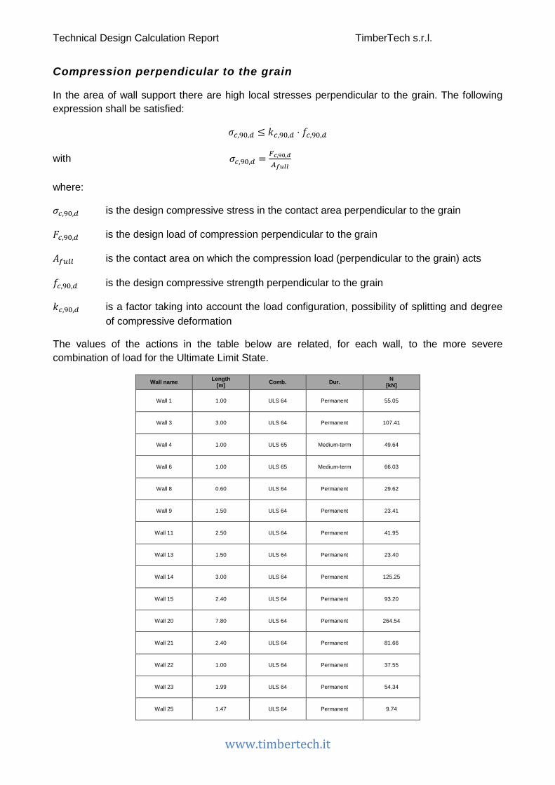
Technical Design Calculation Report TimberTech s.r.l.
www.timbertech.it
Compression perpendicular to the grain
In the area of wall support there are high local stresses perpendicular to the grain. The following expression shall be satisfied:
𝜎𝜎𝑐𝑐,90,𝑑𝑑 ≤ 𝑘𝑘𝑐𝑐,90,𝑑𝑑 ⋅ 𝑓𝑓𝑐𝑐,90,𝑑𝑑
with 𝜎𝜎𝑐𝑐,90,𝑑𝑑 = 𝐹𝐹𝑐𝑐,90,𝑑𝑑𝐴𝐴𝑓𝑓𝑓𝑓𝑓𝑓𝑓𝑓
where:
𝜎𝜎𝑐𝑐,90,𝑑𝑑 is the design compressive stress in the contact area perpendicular to the grain
𝐹𝐹𝑐𝑐,90,𝑑𝑑 is the design load of compression perpendicular to the grain
𝐴𝐴𝑒𝑒𝑓𝑓𝑖𝑖𝑖𝑖 is the contact area on which the compression load (perpendicular to the grain) acts
𝑓𝑓𝑐𝑐,90,𝑑𝑑 is the design compressive strength perpendicular to the grain
𝑘𝑘𝑐𝑐,90,𝑑𝑑 is a factor taking into account the load configuration, possibility of splitting and degree of compressive deformation
The values of the actions in the table below are related, for each wall, to the more severe combination of load for the Ultimate Limit State.
Wall name Length [m] Comb. Dur. N
[kN]
Wall 1 1.00 ULS 64 Permanent 55.05
Wall 3 3.00 ULS 64 Permanent 107.41
Wall 4 1.00 ULS 65 Medium-term 49.64
Wall 6 1.00 ULS 65 Medium-term 66.03
Wall 8 0.60 ULS 64 Permanent 29.62
Wall 9 1.50 ULS 64 Permanent 23.41
Wall 11 2.50 ULS 64 Permanent 41.95
Wall 13 1.50 ULS 64 Permanent 23.40
Wall 14 3.00 ULS 64 Permanent 125.25
Wall 15 2.40 ULS 64 Permanent 93.20
Wall 20 7.80 ULS 64 Permanent 264.54
Wall 21 2.40 ULS 64 Permanent 81.66
Wall 22 1.00 ULS 64 Permanent 37.55
Wall 23 1.99 ULS 64 Permanent 54.34
Wall 25 1.47 ULS 64 Permanent 9.74
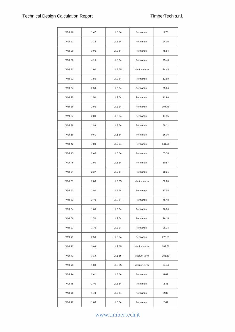
Technical Design Calculation Report TimberTech s.r.l.
www.timbertech.it
Wall 26 1.47 ULS 64 Permanent 9.76
Wall 27 3.14 ULS 64 Permanent 94.05
Wall 29 3.06 ULS 64 Permanent 78.54
Wall 30 4.15 ULS 64 Permanent 25.46
Wall 31 1.00 ULS 65 Medium-term 24.45
Wall 33 1.50 ULS 64 Permanent 13.89
Wall 34 2.50 ULS 64 Permanent 25.64
Wall 35 1.50 ULS 64 Permanent 13.90
Wall 36 2.50 ULS 64 Permanent 104.48
Wall 37 2.80 ULS 64 Permanent 17.55
Wall 38 1.99 ULS 64 Permanent 58.11
Wall 39 0.51 ULS 64 Permanent 26.08
Wall 42 7.80 ULS 64 Permanent 141.06
Wall 43 2.40 ULS 64 Permanent 53.16
Wall 46 1.50 ULS 64 Permanent 10.87
Wall 54 2.37 ULS 64 Permanent 69.91
Wall 61 2.80 ULS 65 Medium-term 52.90
Wall 62 2.80 ULS 64 Permanent 17.55
Wall 63 2.40 ULS 64 Permanent 46.48
Wall 64 1.60 ULS 64 Permanent 26.94
Wall 66 1.70 ULS 64 Permanent 26.15
Wall 67 1.70 ULS 64 Permanent 26.14
Wall 71 2.50 ULS 64 Permanent 228.69
Wall 72 3.06 ULS 65 Medium-term 263.65
Wall 72 3.14 ULS 65 Medium-term 253.13
Wall 73 1.00 ULS 65 Medium-term 24.44
Wall 74 2.41 ULS 64 Permanent 4.07
Wall 75 1.40 ULS 64 Permanent 2.35
Wall 76 1.40 ULS 64 Permanent 2.35
Wall 77 1.60 ULS 64 Permanent 2.69

Technical Design Calculation Report TimberTech s.r.l.
www.timbertech.it
Wall 78 1.73 ULS 64 Permanent 2.91
Wall2 5.07 ULS 64 Permanent 35.20
Wall3 2.80 ULS 64 Permanent 90.02
The compression checks of the CLT panels are performed considering a wall portion of unitary length.
Section: CLT element section
Afull: Contact area on which the compression load (perpendicular to the grain) acts
Comb.: More severe combination of load
kmod: Modification factor taking into account the effect of the duration of load and moisture content
γM: Partial factor for a material property
fc,90,k: Design compressive strength perpendicular to the grain
σc,90,d: Design compressive stress in the contact area perpendicular to the grain
Wall name Section Afull [mm2/m] kc,90 Comb. kmod γM fc,90,k
[MPa] σc,90,d [MPa] Check
Wall 1 CLT 120 mm - 5 layers -
vertical joints 100000 1.5 ULS 64 0.6 1.45 2.5 0.54 32%
Wall 3 CLT 120 mm - 5 layers -
vertical joints 100000 1.5 ULS 64 0.6 1.45 2.5 0.46 27%
Wall 4 CLT 120 mm - 5 layers -
vertical joints 100000 1.5 ULS 65 0.8 1.45 2.5 0.49 22%
Wall 6 CLT 120 mm - 5 layers -
vertical joints 100000 1.5 ULS 65 0.8 1.45 2.5 0.66 29%
Wall 8 CLT 120 mm - 5 layers -
vertical joints 100000 1.5 ULS 64 0.6 1.45 2.5 0.48 29%
Wall 9 CLT 120 mm - 5 layers -
vertical joints 100000 1.5 ULS 64 0.6 1.45 2.5 0.17 10%
Wall 11 CLT 120 mm - 5 layers -
vertical joints 100000 1.5 ULS 64 0.6 1.45 2.5 0.18 10%
Wall 13 CLT 120 mm - 5 layers -
vertical joints 100000 1.5 ULS 64 0.6 1.45 2.5 0.17 10%
Wall 14 CLT 120 mm - 5 layers -
vertical joints 100000 1.5 ULS 64 0.6 1.45 2.5 0.59 35%
Wall 15 CLT 120 mm - 5 layers -
vertical joints 100000 1.5 ULS 64 0.6 1.45 2.5 0.47 28%
Wall 20 CLT 120 mm - 5 layers -
vertical joints 100000 1.5 ULS 64 0.6 1.45 2.5 0.46 27%
Wall 21 CLT 120 mm - 5 layers -
vertical joints 100000 1.5 ULS 64 0.6 1.45 2.5 0.47 28%
Wall 22 CLT 100 mm - 3 layers 100000 1.5 ULS 64 0.6 1.45 2.5 0.37 22%

Technical Design Calculation Report TimberTech s.r.l.
www.timbertech.it
Wall 23 CLT 100 mm - 3 layers 100000 1.5 ULS 64 0.6 1.45 2.5 0.31 19%
Wall 25 CLT 100 mm - 3 layers 100000 1.5 ULS 64 0.6 1.45 2.5 0.07 4%
Wall 26 CLT 100 mm - 3 layers 100000 1.5 ULS 64 0.6 1.45 2.5 0.07 4%
Wall 27 CLT 100 mm - 3 layers 100000 1.5 ULS 64 0.6 1.45 2.5 0.36 22%
Wall 29 CLT 100 mm - 3 layers 100000 1.5 ULS 64 0.6 1.45 2.5 0.36 21%
Wall 30 CLT 100 mm - 3 layers 100000 1.5 ULS 64 0.6 1.45 2.5 0.07 4%
Wall 31 CLT 100 mm - 3 layers 100000 1.5 ULS 65 0.8 1.45 2.5 0.24 11%
Wall 33 CLT 100 mm - 3 layers 100000 1.5 ULS 64 0.6 1.45 2.5 0.11 7%
Wall 34 CLT 100 mm - 3 layers 100000 1.5 ULS 64 0.6 1.45 2.5 0.12 7%
Wall 35 CLT 100 mm - 3 layers 100000 1.5 ULS 64 0.6 1.45 2.5 0.11 7%
Wall 36 CLT 100 mm - 3 layers 100000 1.5 ULS 64 0.6 1.45 2.5 0.74 44%
Wall 37 CLT 100 mm - 3 layers 100000 1.5 ULS 64 0.6 1.45 2.5 0.07 4%
Wall 38 CLT 100 mm - 3 layers 100000 1.5 ULS 64 0.6 1.45 2.5 0.34 20%
Wall 39 CLT 100 mm - 3 layers 100000 1.5 ULS 64 0.6 1.45 2.5 0.50 30%
Wall 42 CLT 100 mm - 3 layers 100000 1.5 ULS 64 0.6 1.45 2.5 0.26 16%
Wall 43 CLT 100 mm - 3 layers 100000 1.5 ULS 64 0.6 1.45 2.5 0.26 16%
Wall 46 CLT 100 mm - 3 layers 100000 1.5 ULS 64 0.6 1.45 2.5 0.08 5%
Wall 54 CLT 120 mm - 5 layers -
vertical joints 100000 1.5 ULS 64 0.6 1.45 2.5 0.45 27%
Wall 61 CLT 120 mm - 5 layers -
vertical joints 100000 1.5 ULS 65 0.8 1.45 2.5 0.32 14%
Wall 62 CLT 100 mm - 3 layers 100000 1.5 ULS 64 0.6 1.45 2.5 0.07 4%
Wall 63 CLT 100 mm - 3 layers 100000 1.5 ULS 64 0.6 1.45 2.5 0.23 14%
Wall 64 CLT 100 mm - 3 layers 100000 1.5 ULS 64 0.6 1.45 2.5 0.17 10%
Wall 66 CLT 120 mm - 5 layers -
vertical joints 100000 1.5 ULS 64 0.6 1.45 2.5 0.16 9%
Wall 67 CLT 120 mm - 5 layers -
vertical joints 100000 1.5 ULS 64 0.6 1.45 2.5 0.15 9%
Wall 71 CLT 120 mm - 5 layers -
vertical joints 100000 1.5 ULS 64 0.6 1.45 2.5 1.35 81%
Wall 72 CLT 120 mm - 5 layers -
vertical joints 100000 1.5 ULS 65 0.8 1.45 2.5 1.08 48%
Wall 72 CLT 120 mm - 5 layers -
vertical joints 100000 1.5 ULS 65 0.8 1.45 2.5 1.07 48%
Wall 73 CLT 100 mm - 3 layers 100000 1.5 ULS 65 0.8 1.45 2.5 0.24 11%
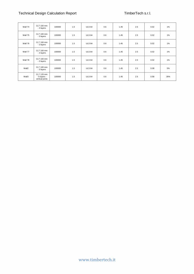
Technical Design Calculation Report TimberTech s.r.l.
www.timbertech.it
Wall 74 CLT 100 mm - 3 layers 100000 1.5 ULS 64 0.6 1.45 2.5 0.02 1%
Wall 75 CLT 100 mm - 3 layers 100000 1.5 ULS 64 0.6 1.45 2.5 0.02 1%
Wall 76 CLT 100 mm - 3 layers 100000 1.5 ULS 64 0.6 1.45 2.5 0.02 1%
Wall 77 CLT 100 mm - 3 layers 100000 1.5 ULS 64 0.6 1.45 2.5 0.02 1%
Wall 78 CLT 100 mm - 3 layers 100000 1.5 ULS 64 0.6 1.45 2.5 0.02 1%
Wall2 CLT 100 mm - 3 layers 100000 1.5 ULS 64 0.6 1.45 2.5 0.08 5%
Wall3 CLT 120 mm - 5 layers -
vertical joints 100000 1.5 ULS 64 0.6 1.45 2.5 0.58 35%

Technical Design Calculation Report TimberTech s.r.l.
www.timbertech.it
Shear (load in-plane)
The internal stress pattern in a CLT element subjected to shear forces can lead to failure of the material in two different mechanisms: shear bearing (mechanism I) in the boards and torsion-like (mechanism II) in the gluing interfaces.
The values of the actions in the table below are related, for each wall, to the more severe combination of load for the shear Ultimate Limit State.
Wall name Length [m] Comb. Dur. V2
[kN]
Wall 1 1.00 Seismic ULS 1 ex- ey+ Instantaneous 3.44
Wall 3 3.00 Seismic ULS 1 ex- ey+ Instantaneous 17.16
Wall 4 1.00 Seismic ULS 6 ex- ey- Instantaneous 12.60
Wall 6 1.00 Seismic ULS 5 ex- ey+ Instantaneous 8.02
Wall 8 0.60 Seismic ULS 1 ex- ey+ Instantaneous 1.28
Wall 9 1.50 Seismic ULS 6 ex- ey- Instantaneous 15.36
Wall 11 2.50 Seismic ULS 6 ex- ey- Instantaneous 27.23
Wall 13 1.50 Seismic ULS 6 ex- ey- Instantaneous 15.36
Wall 14 3.00 Seismic ULS 1 ex- ey+ Instantaneous 17.16
Wall 15 2.40 Seismic ULS 2 ex+ ey+ Instantaneous 11.02
Wall 20 7.80 Seismic ULS 2 ex+ ey+ Instantaneous 48.36
Wall 21 2.40 Seismic ULS 2 ex+ ey+ Instantaneous 11.02
Wall 22 1.00 Seismic ULS 1 ex- ey+ Instantaneous 4.14
Wall 23 1.99 Seismic ULS 1 ex- ey+ Instantaneous 14.44
Wall 25 1.47 Seismic ULS 1 ex- ey+ Instantaneous 7.50
Wall 26 1.47 Seismic ULS 1 ex- ey+ Instantaneous 7.37
Wall 27 3.14 Seismic ULS 1 ex- ey+ Instantaneous 8.73
Wall 29 3.06 Seismic ULS 1 ex- ey+ Instantaneous 8.32
Wall 31 1.00 Seismic ULS 5 ex- ey+ Instantaneous 9.60
Wall 33 1.50 Seismic ULS 6 ex- ey- Instantaneous 11.81
Wall 34 2.50 Seismic ULS 6 ex- ey- Instantaneous 17.26
Wall 35 1.50 Seismic ULS 6 ex- ey- Instantaneous 11.53
Wall 36 2.50 Seismic ULS 1 ex- ey+ Instantaneous 5.73
Wall 38 1.99 Seismic ULS 1 ex- ey+ Instantaneous 14.44

Technical Design Calculation Report TimberTech s.r.l.
www.timbertech.it
Wall 39 0.51 Seismic ULS 1 ex- ey+ Instantaneous 1.10
Wall 42 7.80 Seismic ULS 2 ex+ ey+ Instantaneous 50.77
Wall 43 2.40 Seismic ULS 2 ex+ ey+ Instantaneous 6.14
Wall 46 1.50 Seismic ULS 5 ex- ey+ Instantaneous 21.03
Wall 54 2.37 Seismic ULS 5 ex- ey+ Instantaneous 30.29
Wall 61 2.80 Seismic ULS 6 ex- ey- Instantaneous 34.08
Wall 62 2.80 Seismic ULS 5 ex- ey+ Instantaneous 35.89
Wall 63 2.40 Seismic ULS 2 ex+ ey+ Instantaneous 7.11
Wall 66 1.70 Seismic ULS 1 ex- ey+ Instantaneous 10.17
Wall 67 1.70 Seismic ULS 1 ex- ey+ Instantaneous 10.17
Wall 71 2.50 Seismic ULS 1 ex- ey+ Instantaneous 10.06
Wall 72 3.06 Seismic ULS 1 ex- ey+ Instantaneous 14.68
Wall 72 3.14 Seismic ULS 1 ex- ey+ Instantaneous 15.40
Wall 73 1.00 Seismic ULS 5 ex- ey+ Instantaneous 7.37
Wall3 2.80 Seismic ULS 5 ex- ey+ Instantaneous 31.89
Mechanism I - shear
The internal shear stress can be evaluated as
[omissis]
where
𝑎𝑎2 is the shear force per linear metre acting on the CLT element
𝑎𝑎𝑖𝑖,𝑚𝑚𝑥𝑥𝑡𝑡 is the thickness of the i-th layer having orientation parallel to the external layers
𝑎𝑎𝑖𝑖,𝑖𝑖𝑚𝑚𝑡𝑡 is the thickness of the i-th layer having orientation parallel to the internal layers
𝜏𝜏𝑧𝑧 is the shear stress acting on the layers having orientation parallel to the external layers
𝜏𝜏𝑦𝑦 is the shear stress acting on the layers having orientation parallel to the internal layers
The stress to be used in the checks is the maximum between the two:
𝜏𝜏𝑑𝑑 = 𝑡𝑡𝑎𝑎𝑚𝑚(𝜏𝜏𝑧𝑧; 𝜏𝜏𝑦𝑦)
The following expression shall be satisfied
𝜏𝜏𝑑𝑑 ≤ 𝑓𝑓𝑣𝑣,𝑖𝑖𝑚𝑚𝑠𝑠𝑡𝑡𝑟𝑟𝑚𝑚,𝑑𝑑

Technical Design Calculation Report TimberTech s.r.l.
www.timbertech.it
being
𝑓𝑓𝑣𝑣,𝑑𝑑 the shear strength calculated as
𝑓𝑓𝑣𝑣,𝑑𝑑 =𝑘𝑘𝑚𝑚𝑚𝑚𝑑𝑑 ⋅ 𝑓𝑓𝑣𝑣,𝑘𝑘
𝛾𝛾𝑀𝑀
Mechanism II – torsion
The internal torsional stress can be expressed as
[omissis]
being:
𝑀𝑀𝑇𝑇 the internal torsional moment
𝑊𝑊 the polar moment of resistance
The polar moment of resistance is defined by the following expression
[omissis]
where aref is the average width of the boards assumed equal to 150 mm.
[omissis]
The following expression shall be satisfied
𝜏𝜏𝑇𝑇,𝑑𝑑 ≤ 𝑓𝑓𝑇𝑇,𝑑𝑑
being
𝑓𝑓𝑇𝑇,𝑑𝑑 the design value of the torsional strength of glued interfaces
𝑓𝑓𝑇𝑇,𝑑𝑑 =𝑘𝑘𝑚𝑚𝑚𝑚𝑑𝑑 ⋅ 𝑓𝑓𝑇𝑇,𝑘𝑘
𝛾𝛾𝑀𝑀
Below is the table with the shear checks for each CLT wall. The two different mechanisms (shear and torsion) are verified.
Comb.: More severe combination of load
kmod: Modification factor taking into account the effect of the duration of load and moisture content
γM: Partial factor for a material property
fv,k: CLT characteristic shear strength (Mechanism I)
τd: Design shear stress in the layers
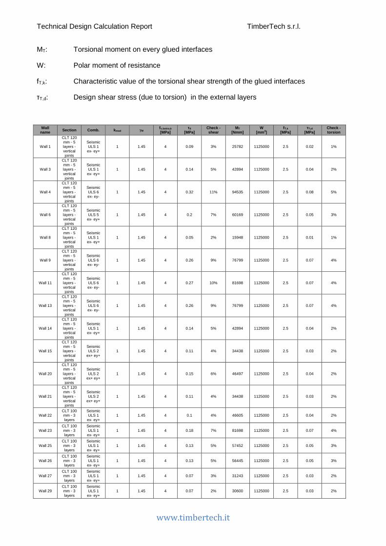
Technical Design Calculation Report TimberTech s.r.l.
www.timbertech.it
MT: Torsional moment on every glued interfaces
W: Polar moment of resistance
fT,k: Characteristic value of the torsional shear strength of the glued interfaces
τT,d: Design shear stress (due to torsion) in the external layers
Wall name Section Comb. kmod γM fv,lastra,k
[MPa] τd
[MPa] Check - shear
MT [Nmm]
W [mm3]
fT,k [MPa]
τT,d [MPa]
Check - torsion
Wall 1
CLT 120 mm - 5 layers - vertical joints
Seismic ULS 1 ex- ey+
1 1.45 4 0.09 3% 25782 1125000 2.5 0.02 1%
Wall 3
CLT 120 mm - 5 layers - vertical joints
Seismic ULS 1 ex- ey+
1 1.45 4 0.14 5% 42894 1125000 2.5 0.04 2%
Wall 4
CLT 120 mm - 5 layers - vertical joints
Seismic ULS 6 ex- ey-
1 1.45 4 0.32 11% 94535 1125000 2.5 0.08 5%
Wall 6
CLT 120 mm - 5 layers - vertical joints
Seismic ULS 5 ex- ey+
1 1.45 4 0.2 7% 60169 1125000 2.5 0.05 3%
Wall 8
CLT 120 mm - 5 layers - vertical joints
Seismic ULS 1 ex- ey+
1 1.45 4 0.05 2% 15948 1125000 2.5 0.01 1%
Wall 9
CLT 120 mm - 5 layers - vertical joints
Seismic ULS 6 ex- ey-
1 1.45 4 0.26 9% 76799 1125000 2.5 0.07 4%
Wall 11
CLT 120 mm - 5 layers - vertical joints
Seismic ULS 6 ex- ey-
1 1.45 4 0.27 10% 81698 1125000 2.5 0.07 4%
Wall 13
CLT 120 mm - 5 layers - vertical joints
Seismic ULS 6 ex- ey-
1 1.45 4 0.26 9% 76799 1125000 2.5 0.07 4%
Wall 14
CLT 120 mm - 5 layers - vertical joints
Seismic ULS 1 ex- ey+
1 1.45 4 0.14 5% 42894 1125000 2.5 0.04 2%
Wall 15
CLT 120 mm - 5 layers - vertical joints
Seismic ULS 2
ex+ ey+ 1 1.45 4 0.11 4% 34438 1125000 2.5 0.03 2%
Wall 20
CLT 120 mm - 5 layers - vertical joints
Seismic ULS 2
ex+ ey+ 1 1.45 4 0.15 6% 46497 1125000 2.5 0.04 2%
Wall 21
CLT 120 mm - 5 layers - vertical joints
Seismic ULS 2
ex+ ey+ 1 1.45 4 0.11 4% 34438 1125000 2.5 0.03 2%
Wall 22 CLT 100 mm - 3 layers
Seismic ULS 1 ex- ey+
1 1.45 4 0.1 4% 46605 1125000 2.5 0.04 2%
Wall 23 CLT 100 mm - 3 layers
Seismic ULS 1 ex- ey+
1 1.45 4 0.18 7% 81698 1125000 2.5 0.07 4%
Wall 25 CLT 100 mm - 3 layers
Seismic ULS 1 ex- ey+
1 1.45 4 0.13 5% 57452 1125000 2.5 0.05 3%
Wall 26 CLT 100 mm - 3 layers
Seismic ULS 1 ex- ey+
1 1.45 4 0.13 5% 56445 1125000 2.5 0.05 3%
Wall 27 CLT 100 mm - 3 layers
Seismic ULS 1 ex- ey+
1 1.45 4 0.07 3% 31243 1125000 2.5 0.03 2%
Wall 29 CLT 100 mm - 3 layers
Seismic ULS 1 ex- ey+
1 1.45 4 0.07 2% 30600 1125000 2.5 0.03 2%

Technical Design Calculation Report TimberTech s.r.l.
www.timbertech.it
Wall 31 CLT 100 mm - 3 layers
Seismic ULS 5 ex- ey+
1 1.45 4 0.24 9% 107983 1125000 2.5 0.1 6%
Wall 33 CLT 100 mm - 3 layers
Seismic ULS 6 ex- ey-
1 1.45 4 0.2 7% 88565 1125000 2.5 0.08 5%
Wall 34 CLT 100 mm - 3 layers
Seismic ULS 6 ex- ey-
1 1.45 4 0.17 6% 77673 1125000 2.5 0.07 4%
Wall 35 CLT 100 mm - 3 layers
Seismic ULS 6 ex- ey-
1 1.45 4 0.19 7% 86474 1125000 2.5 0.08 4%
Wall 36 CLT 100 mm - 3 layers
Seismic ULS 1 ex- ey+
1 1.45 4 0.06 2% 25767 1125000 2.5 0.02 1%
Wall 38 CLT 100 mm - 3 layers
Seismic ULS 1 ex- ey+
1 1.45 4 0.18 7% 81698 1125000 2.5 0.07 4%
Wall 39 CLT 100 mm - 3 layers
Seismic ULS 1 ex- ey+
1 1.45 4 0.05 2% 24194 1125000 2.5 0.02 1%
Wall 42 CLT 100 mm - 3 layers
Seismic ULS 2
ex+ ey+ 1 1.45 4 0.16 6% 73233 1125000 2.5 0.07 4%
Wall 43 CLT 100 mm - 3 layers
Seismic ULS 2
ex+ ey+ 1 1.45 4 0.06 2% 28767 1125000 2.5 0.03 1%
Wall 46 CLT 100 mm - 3 layers
Seismic ULS 5 ex- ey+
1 1.45 4 0.35 13% 157748 1125000 2.5 0.14 8%
Wall 54
CLT 120 mm - 5 layers - vertical joints
Seismic ULS 5 ex- ey+
1 1.45 4 0.32 12% 95843 1125000 2.5 0.09 5%
Wall 61
CLT 120 mm - 5 layers - vertical joints
Seismic ULS 6 ex- ey-
1 1.45 4 0.3 11% 91288 1125000 2.5 0.08 5%
Wall 62 CLT 100 mm - 3 layers
Seismic ULS 5 ex- ey+
1 1.45 4 0.32 12% 144196 1125000 2.5 0.13 7%
Wall 63 CLT 100 mm - 3 layers
Seismic ULS 2
ex+ ey+ 1 1.45 4 0.07 3% 33326 1125000 2.5 0.03 2%
Wall 66
CLT 120 mm - 5 layers - vertical joints
Seismic ULS 1 ex- ey+
1 1.45 4 0.15 5% 44854 1125000 2.5 0.04 2%
Wall 67
CLT 120 mm - 5 layers - vertical joints
Seismic ULS 1 ex- ey+
1 1.45 4 0.15 5% 44854 1125000 2.5 0.04 2%
Wall 71
CLT 120 mm - 5 layers - vertical joints
Seismic ULS 1 ex- ey+
1 1.45 4 0.1 4% 30193 1125000 2.5 0.03 2%
Wall 72
CLT 120 mm - 5 layers - vertical joints
Seismic ULS 1 ex- ey+
1 1.45 4 0.12 4% 35975 1125000 2.5 0.03 2%
Wall 72
CLT 120 mm - 5 layers - vertical joints
Seismic ULS 1 ex- ey+
1 1.45 4 0.12 4% 36754 1125000 2.5 0.03 2%
Wall 73 CLT 100 mm - 3 layers
Seismic ULS 5 ex- ey+
1 1.45 4 0.18 7% 82865 1125000 2.5 0.07 4%
Wall3
CLT 120 mm - 5 layers - vertical joints
Seismic ULS 5 ex- ey+
1 1.45 4 0.28 10% 85412 1125000 2.5 0.08 4%

Technical Design Calculation Report TimberTech s.r.l.
www.timbertech.it
Vertical joints among CLT panels of a wall
The values of the actions in the vertical joints are summarized in the table below. They are related, for each wall, to the more severe combination of load for the shear Ultimate Limit State.
Wall name Wall height [m] Comb. Dur. V2
[kN] Vjoint,d [kN]
Wall 1 3.2 Seismic ULS 1 ex- ey+ Instantaneous 3.44 11
Wall 3 3.2 Seismic ULS 1 ex- ey+ Instantaneous 17.16 18.3
Wall 4 3.2 Seismic ULS 6 ex- ey- Instantaneous 12.6 40.33
Wall 6 3.2 Seismic ULS 5 ex- ey+ Instantaneous 8.02 25.67
Wall 8 3.2 Seismic ULS 1 ex- ey+ Instantaneous 1.28 6.8
Wall 9 3.2 Seismic ULS 6 ex- ey- Instantaneous 15.36 32.77
Wall 11 3.2 Seismic ULS 6 ex- ey- Instantaneous 27.23 34.86
Wall 13 3.2 Seismic ULS 6 ex- ey- Instantaneous 15.36 32.77
Wall 14 3.2 Seismic ULS 1 ex- ey+ Instantaneous 17.16 18.3
Wall 15 3.2 Seismic ULS 2 ex+ ey+ Instantaneous 11.02 14.69
Wall 20 3.2 Seismic ULS 2 ex+ ey+ Instantaneous 48.36 19.84
Wall 21 3.2 Seismic ULS 2 ex+ ey+ Instantaneous 11.02 14.69
Wall 54 3.2 Seismic ULS 5 ex- ey+ Instantaneous 30.29 40.89
Wall 61 3.2 Seismic ULS 6 ex- ey- Instantaneous 34.08 38.95
Wall 66 3.2 Seismic ULS 1 ex- ey+ Instantaneous 10.17 19.14
Wall 67 3.2 Seismic ULS 1 ex- ey+ Instantaneous 10.17 19.14
Wall 71 3.2 Seismic ULS 1 ex- ey+ Instantaneous 10.06 12.88
Wall 72 3.2 Seismic ULS 1 ex- ey+ Instantaneous 14.68 15.35
Wall 72 3.2 Seismic ULS 1 ex- ey+ Instantaneous 15.4 15.68
Wall3 3.2 Seismic ULS 5 ex- ey+ Instantaneous 31.89 36.44
Vertical joints in CLT walls – Fasteners strength
The resistance of vertical joints in CLT walls is calculated in accordance to EN 1995-1-1. The resistance of the joints of each wall can be calculated by the following formula
Rv,k =Fv,k ⋅ h
s
where

Technical Design Calculation Report TimberTech s.r.l.
www.timbertech.it
Rv,k is the characteristic shear resistance of the vertical joints among CLT panels of a wall
Fv,k is the characteristic load-carrying capacity of a single fastener
h is the height of the wall in correspondence of the joint
s is the spacing of the vertical joint fasteners
The characteristic shear resistance of the vertical joint is
𝑅𝑅𝑣𝑣,𝑑𝑑 =𝑘𝑘𝑚𝑚𝑚𝑚𝑑𝑑 ⋅ Rv,k
𝛾𝛾𝑀𝑀
where
𝑘𝑘𝑚𝑚𝑚𝑚𝑑𝑑 is the modification factor taking into account the effect of the duration of load and moisture content
𝛾𝛾𝑀𝑀 is the partial factor for connections
Characteristic load-carrying capacity of the fasteners
The load-carrying capacity of the fasteners is calculated in accordance with Johansen theory (8.2.2 of EN 1995-1-1) for the case timber-to-timber connection in single shear.
The characteristic load-carrying capacity per shear plane per fastener, should be taken as the minimum value found from the following expressions:
- Single shear
𝐹𝐹𝑣𝑣,𝑅𝑅𝑘𝑘,𝑚𝑚 = 𝑓𝑓ℎ,1,𝑘𝑘 ⋅ 𝑎𝑎1 ⋅ 𝑜𝑜
𝐹𝐹𝑣𝑣,𝑅𝑅𝑘𝑘,𝑏𝑏 = 𝑓𝑓ℎ,2,𝑘𝑘 ⋅ 𝑎𝑎2 ⋅ 𝑜𝑜
𝐹𝐹𝑣𝑣,𝑅𝑅𝑘𝑘,𝑐𝑐 = 𝑓𝑓ℎ,1,𝑘𝑘 ⋅ 𝑎𝑎1 ⋅ 𝑜𝑜
1 + 𝛽𝛽⋅ ��𝛽𝛽 + 2𝛽𝛽2 �1 +
𝑎𝑎2𝑎𝑎1
+ �𝑎𝑎2𝑎𝑎1�2� + 𝛽𝛽3 �
𝑎𝑎2𝑎𝑎1�2− 𝛽𝛽 �1 +
𝑎𝑎2𝑎𝑎1��
𝐹𝐹𝑣𝑣,𝑅𝑅𝑘𝑘,𝑑𝑑 = 1,05 ⋅ 𝑒𝑒ℎ,1,𝑘𝑘⋅𝑡𝑡1⋅𝑑𝑑2+𝛽𝛽
⋅ ��2𝛽𝛽(1 + 𝛽𝛽) + 4𝛽𝛽(2+𝛽𝛽)𝑀𝑀𝑦𝑦,𝑅𝑅𝑘𝑘
𝑒𝑒ℎ,1,𝑘𝑘⋅𝑑𝑑⋅𝑡𝑡12− 𝛽𝛽�
𝐹𝐹𝑣𝑣,𝑅𝑅𝑘𝑘,𝑚𝑚 = 1,05 ⋅ 𝑓𝑓ℎ,1,𝑘𝑘 ⋅ 𝑎𝑎2 ⋅ 𝑜𝑜
1 + 2𝛽𝛽⋅ ��2𝛽𝛽2(1 + 𝛽𝛽) +
4𝛽𝛽(1 + 2𝛽𝛽)𝑀𝑀𝑦𝑦,𝑅𝑅𝑘𝑘
𝑓𝑓ℎ,1,𝑘𝑘 ⋅ 𝑜𝑜 ⋅ 𝑎𝑎22− 𝛽𝛽�
𝐹𝐹𝑣𝑣,𝑅𝑅𝑘𝑘,𝑒𝑒 = 1,15 ⋅ �2𝛽𝛽
1 + 𝛽𝛽�2 ⋅ 𝑀𝑀𝑦𝑦,𝑅𝑅𝑘𝑘 ⋅ 𝑓𝑓ℎ,1,𝑘𝑘 ⋅ 𝑜𝑜
Figura: Failure modes for timber and panel connections (Single shear).

Technical Design Calculation Report TimberTech s.r.l.
www.timbertech.it
- Double shear
𝐹𝐹𝑣𝑣,𝑅𝑅𝑘𝑘,𝑔𝑔 = 𝑓𝑓ℎ,1,𝑘𝑘 ⋅ 𝑎𝑎1 ⋅ 𝑜𝑜
𝐹𝐹𝑣𝑣,𝑅𝑅𝑘𝑘,ℎ = 0.5 ⋅ 𝑓𝑓ℎ,2,𝑘𝑘 ⋅ 𝑎𝑎2 ⋅ 𝑜𝑜
𝐹𝐹𝑣𝑣,𝑅𝑅𝑘𝑘,𝑗𝑗 = 1,05 ⋅ 𝑓𝑓ℎ,1,𝑘𝑘 ⋅ 𝑎𝑎1 ⋅ 𝑜𝑜
2 + 𝛽𝛽⋅ ��2𝛽𝛽(1 + 𝛽𝛽) +
4𝛽𝛽(2 + 𝛽𝛽)𝑀𝑀𝑦𝑦,𝑅𝑅𝑘𝑘
𝑓𝑓ℎ,1,𝑘𝑘 ⋅ 𝑜𝑜 ⋅ 𝑎𝑎12− 𝛽𝛽�
𝐹𝐹𝑣𝑣,𝑅𝑅𝑘𝑘,𝑘𝑘 = 1,15 ⋅ �2𝛽𝛽
1 + 𝛽𝛽�2 ⋅ 𝑀𝑀𝑦𝑦,𝑅𝑅𝑘𝑘 ⋅ 𝑓𝑓ℎ,1,𝑘𝑘 ⋅ 𝑜𝑜
Below is the table with the characteristic load-carrying capacity of the fasteners.
Section Fastener Kser [N/mm] Failure mode Fv,Rk
[N]
CLT 120 mm - 5 layers - vertical joints HBS 10 x 120 2635 c 4668
Vertical joints in CLT walls – Fasteners strength check
The table below illustrates the geometric characteristics of the panels of every wall and the shear bearing capacity Rv,k of the vertical joints.
Wall name Section Height of the
joint [mm]
sc [mm]
Rv,k [kN]
Wall 1 CLT 120 mm - 5 layers - vertical
joints 3200 250 59.75
Wall 3 CLT 120 mm - 5 layers - vertical
joints 3200 250 59.75
Wall 4 CLT 120 mm - 5 layers - vertical
joints 3200 250 59.75
Wall 6 CLT 120 mm - 5 layers - vertical
joints 3200 250 59.75
Wall 8 CLT 120 mm - 5 layers - vertical
joints 3200 250 59.75
Figura: Failure modes for timber and panel connections (Double shear).
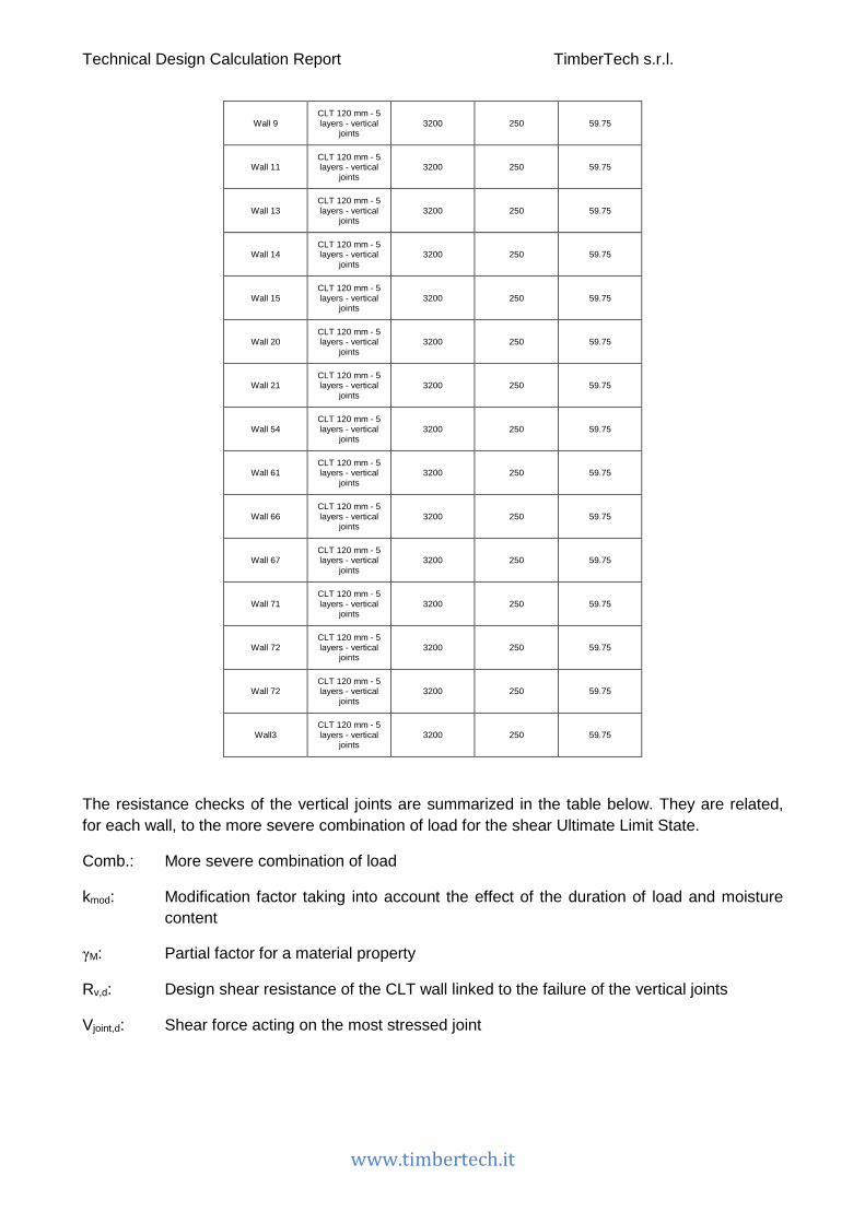
Technical Design Calculation Report TimberTech s.r.l.
www.timbertech.it
Wall 9 CLT 120 mm - 5 layers - vertical
joints 3200 250 59.75
Wall 11 CLT 120 mm - 5 layers - vertical
joints 3200 250 59.75
Wall 13 CLT 120 mm - 5 layers - vertical
joints 3200 250 59.75
Wall 14 CLT 120 mm - 5 layers - vertical
joints 3200 250 59.75
Wall 15 CLT 120 mm - 5 layers - vertical
joints 3200 250 59.75
Wall 20 CLT 120 mm - 5 layers - vertical
joints 3200 250 59.75
Wall 21 CLT 120 mm - 5 layers - vertical
joints 3200 250 59.75
Wall 54 CLT 120 mm - 5 layers - vertical
joints 3200 250 59.75
Wall 61 CLT 120 mm - 5 layers - vertical
joints 3200 250 59.75
Wall 66 CLT 120 mm - 5 layers - vertical
joints 3200 250 59.75
Wall 67 CLT 120 mm - 5 layers - vertical
joints 3200 250 59.75
Wall 71 CLT 120 mm - 5 layers - vertical
joints 3200 250 59.75
Wall 72 CLT 120 mm - 5 layers - vertical
joints 3200 250 59.75
Wall 72 CLT 120 mm - 5 layers - vertical
joints 3200 250 59.75
Wall3 CLT 120 mm - 5 layers - vertical
joints 3200 250 59.75
The resistance checks of the vertical joints are summarized in the table below. They are related, for each wall, to the more severe combination of load for the shear Ultimate Limit State.
Comb.: More severe combination of load
kmod: Modification factor taking into account the effect of the duration of load and moisture content
γM: Partial factor for a material property
Rv,d: Design shear resistance of the CLT wall linked to the failure of the vertical joints
Vjoint,d: Shear force acting on the most stressed joint
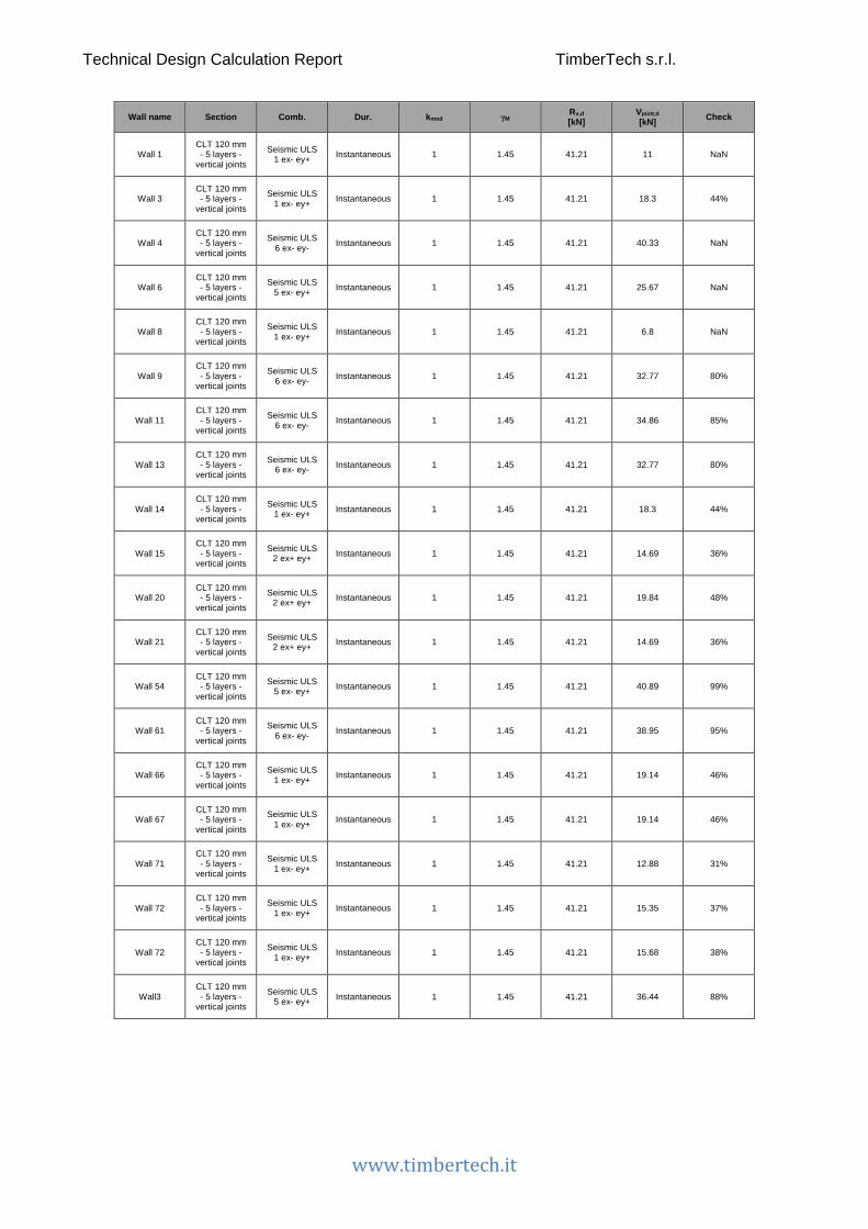
Technical Design Calculation Report TimberTech s.r.l.
www.timbertech.it
Wall name Section Comb. Dur. kmod γM Rv,d [kN]
Vjoint,d [kN] Check
Wall 1 CLT 120 mm - 5 layers -
vertical joints
Seismic ULS 1 ex- ey+ Instantaneous 1 1.45 41.21 11 NaN
Wall 3 CLT 120 mm - 5 layers -
vertical joints
Seismic ULS 1 ex- ey+ Instantaneous 1 1.45 41.21 18.3 44%
Wall 4 CLT 120 mm - 5 layers -
vertical joints
Seismic ULS 6 ex- ey- Instantaneous 1 1.45 41.21 40.33 NaN
Wall 6 CLT 120 mm - 5 layers -
vertical joints
Seismic ULS 5 ex- ey+ Instantaneous 1 1.45 41.21 25.67 NaN
Wall 8 CLT 120 mm - 5 layers -
vertical joints
Seismic ULS 1 ex- ey+ Instantaneous 1 1.45 41.21 6.8 NaN
Wall 9 CLT 120 mm - 5 layers -
vertical joints
Seismic ULS 6 ex- ey- Instantaneous 1 1.45 41.21 32.77 80%
Wall 11 CLT 120 mm - 5 layers -
vertical joints
Seismic ULS 6 ex- ey- Instantaneous 1 1.45 41.21 34.86 85%
Wall 13 CLT 120 mm - 5 layers -
vertical joints
Seismic ULS 6 ex- ey- Instantaneous 1 1.45 41.21 32.77 80%
Wall 14 CLT 120 mm - 5 layers -
vertical joints
Seismic ULS 1 ex- ey+ Instantaneous 1 1.45 41.21 18.3 44%
Wall 15 CLT 120 mm - 5 layers -
vertical joints
Seismic ULS 2 ex+ ey+ Instantaneous 1 1.45 41.21 14.69 36%
Wall 20 CLT 120 mm - 5 layers -
vertical joints
Seismic ULS 2 ex+ ey+ Instantaneous 1 1.45 41.21 19.84 48%
Wall 21 CLT 120 mm - 5 layers -
vertical joints
Seismic ULS 2 ex+ ey+ Instantaneous 1 1.45 41.21 14.69 36%
Wall 54 CLT 120 mm - 5 layers -
vertical joints
Seismic ULS 5 ex- ey+ Instantaneous 1 1.45 41.21 40.89 99%
Wall 61 CLT 120 mm - 5 layers -
vertical joints
Seismic ULS 6 ex- ey- Instantaneous 1 1.45 41.21 38.95 95%
Wall 66 CLT 120 mm - 5 layers -
vertical joints
Seismic ULS 1 ex- ey+ Instantaneous 1 1.45 41.21 19.14 46%
Wall 67 CLT 120 mm - 5 layers -
vertical joints
Seismic ULS 1 ex- ey+ Instantaneous 1 1.45 41.21 19.14 46%
Wall 71 CLT 120 mm - 5 layers -
vertical joints
Seismic ULS 1 ex- ey+ Instantaneous 1 1.45 41.21 12.88 31%
Wall 72 CLT 120 mm - 5 layers -
vertical joints
Seismic ULS 1 ex- ey+ Instantaneous 1 1.45 41.21 15.35 37%
Wall 72 CLT 120 mm - 5 layers -
vertical joints
Seismic ULS 1 ex- ey+ Instantaneous 1 1.45 41.21 15.68 38%
Wall3 CLT 120 mm - 5 layers -
vertical joints
Seismic ULS 5 ex- ey+ Instantaneous 1 1.45 41.21 36.44 88%
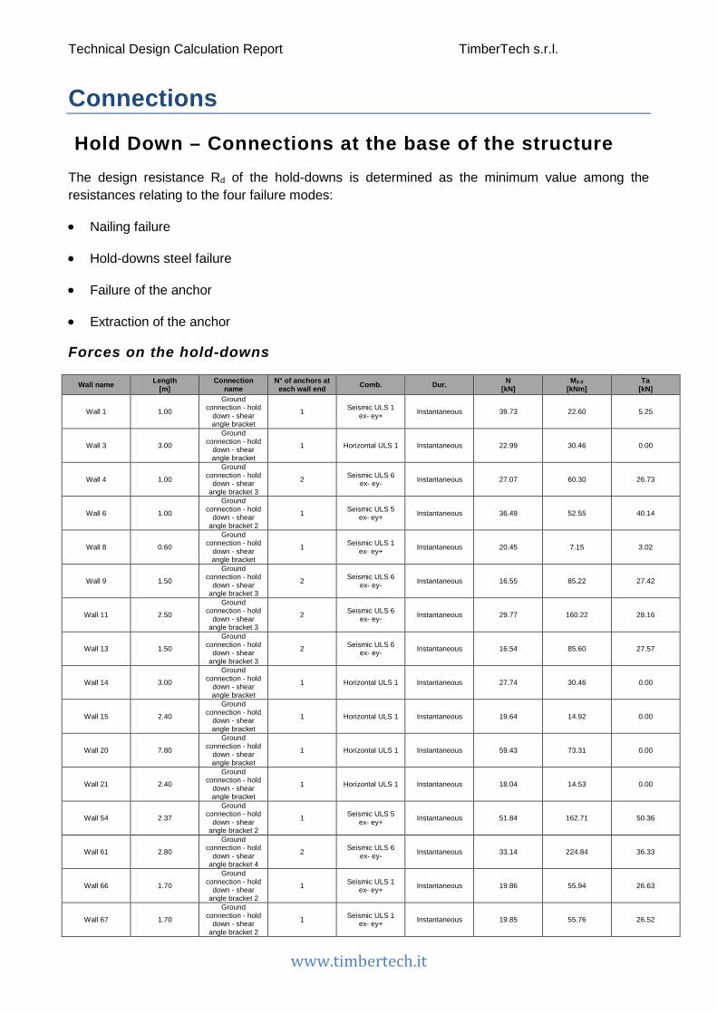
Technical Design Calculation Report TimberTech s.r.l.
www.timbertech.it
Connections
Hold Down – Connections at the base of the structure The design resistance Rd of the hold-downs is determined as the minimum value among the resistances relating to the four failure modes:
• Nailing failure
• Hold-downs steel failure
• Failure of the anchor
• Extraction of the anchor
Forces on the hold-downs
Wall name Length [m]
Connection name
N° of anchors at each wall end Comb. Dur. N
[kN] M3-3
[kNm] Ta
[kN]
Wall 1 1.00
Ground connection - hold
down - shear angle bracket
1 Seismic ULS 1 ex- ey+ Instantaneous 39.73 22.60 5.25
Wall 3 3.00
Ground connection - hold
down - shear angle bracket
1 Horizontal ULS 1 Instantaneous 22.99 30.46 0.00
Wall 4 1.00
Ground connection - hold
down - shear angle bracket 3
2 Seismic ULS 6 ex- ey- Instantaneous 27.07 60.30 26.73
Wall 6 1.00
Ground connection - hold
down - shear angle bracket 2
1 Seismic ULS 5 ex- ey+ Instantaneous 36.49 52.55 40.14
Wall 8 0.60
Ground connection - hold
down - shear angle bracket
1 Seismic ULS 1 ex- ey+ Instantaneous 20.45 7.15 3.02
Wall 9 1.50
Ground connection - hold
down - shear angle bracket 3
2 Seismic ULS 6 ex- ey- Instantaneous 16.55 85.22 27.42
Wall 11 2.50
Ground connection - hold
down - shear angle bracket 3
2 Seismic ULS 6 ex- ey- Instantaneous 29.77 160.22 28.16
Wall 13 1.50
Ground connection - hold
down - shear angle bracket 3
2 Seismic ULS 6 ex- ey- Instantaneous 16.54 85.60 27.57
Wall 14 3.00
Ground connection - hold
down - shear angle bracket
1 Horizontal ULS 1 Instantaneous 27.74 30.46 0.00
Wall 15 2.40
Ground connection - hold
down - shear angle bracket
1 Horizontal ULS 1 Instantaneous 19.64 14.92 0.00
Wall 20 7.80
Ground connection - hold
down - shear angle bracket
1 Horizontal ULS 1 Instantaneous 59.43 73.31 0.00
Wall 21 2.40
Ground connection - hold
down - shear angle bracket
1 Horizontal ULS 1 Instantaneous 18.04 14.53 0.00
Wall 54 2.37
Ground connection - hold
down - shear angle bracket 2
1 Seismic ULS 5 ex- ey+ Instantaneous 51.84 162.71 50.36
Wall 61 2.80
Ground connection - hold
down - shear angle bracket 4
2 Seismic ULS 6 ex- ey- Instantaneous 33.14 224.84 36.33
Wall 66 1.70
Ground connection - hold
down - shear angle bracket 2
1 Seismic ULS 1 ex- ey+ Instantaneous 19.86 55.94 26.63
Wall 67 1.70
Ground connection - hold
down - shear angle bracket 2
1 Seismic ULS 1 ex- ey+ Instantaneous 19.85 55.76 26.52
Technical Design Calculation Report TimberTech s.r.l.
www.timbertech.it
Wall 71 2.50
Ground connection - hold
down - shear angle bracket
1 Horizontal ULS 1 Instantaneous 48.36 18.76 0.00
Wall 72 3.06
Ground connection - hold
down - shear angle bracket
1 Horizontal ULS 1 Instantaneous 43.38 27.34 0.00
Wall 72 3.14
Ground connection - hold
down - shear angle bracket
1 Horizontal ULS 1 Instantaneous 38.88 28.68 0.00
Wall3 2.80
Ground connection - hold
down - shear angle bracket 2
1 Horizontal ULS 2 Instantaneous 23.62 50.39 8.19
Nailing resistance
The design value of the load-bearing capacity of the nailing is given by the following expression
𝑅𝑅𝑐𝑐,𝑑𝑑 =𝑘𝑘𝑚𝑚𝑚𝑚𝑑𝑑 ⋅ Rc,k,dens
𝛾𝛾𝑀𝑀
where
Rc,k,dens is the characteristic resistance of the nailing, corrected to take account of the actual
density of the material used according to the formula Rc,k,dens = Rc,k ⋅ �ρk350
�2 where Rc,k
was evaluated as described in the document ETA-11/0086 for WHT 340-440-540-620, and as described in ETA-09/0324 for WKR285, or on the basis of the data introduced by the user
𝑘𝑘𝑚𝑚𝑚𝑚𝑑𝑑 is the modification factor taking into account the effect of the duration of load and moisture content
𝛾𝛾𝑀𝑀 is the is the partial factor for the connections
Hold-down steel resistance
The tensile design strength of the hold-down can be evaluated according to the formula
Rs,d =Rs,k γM2
where
Rs,k is the characteristic value of the resistance of the angle bracket obtained in the document ETA-11/0086 for WHT 340-440-540-620, and obtained in the document ETA-09/0324 for WKR285, or on the basis of the data introduced by the user;
γM2 is the partial factor for resistance of cross-sections in tension to fracture.

Technical Design Calculation Report TimberTech s.r.l.
www.timbertech.it
Tension resistance of the anchor
The tension resistance of the anchor is evaluated as reported in the table 3.4 of EN 1993-1-8 by the following formula
Rt,d =0.9 ⋅ fub ⋅ As
γM2
being:
fub is the ultimate tensile strength of the anchor
As the resistant area of the threaded portion of the shank of the anchor
γM2 is the partial factor for resistance of cross-sections in tension to fracture
Pull-out resistance of the anchor
The characteristic value of pull-out resistance refers to a single anchor regardless of the effects due to the spacing or distances from the edges. Moreover concrete is considered to be non-cracked concrete, dry and at a standard temperature for the actual depth of anchorage
The design pull-out resistance can be calculated as
𝑅𝑅𝑖𝑖𝑓𝑓𝑖𝑖𝑖𝑖,𝑑𝑑 =𝑅𝑅𝑖𝑖𝑓𝑓𝑖𝑖𝑖𝑖,𝑘𝑘𝛾𝛾𝑀𝑀𝑐𝑐
where
𝑅𝑅𝑖𝑖𝑓𝑓𝑖𝑖𝑖𝑖,𝑘𝑘 is the characteristic value of the pull-out resistance is calculated in accordance with the instructions of the European Technical Approval ETA-09/0078
𝛾𝛾𝑀𝑀𝑐𝑐 is the corresponding partial safety factor assumed as proposed in the document ETA-09/0078
The checks are summarized in the following table which shows the characteristic values of the resistances associated with collapse of the various components.
Name: Name of the connection in which the hold-down is used
Comb.: More severe combination of load
TEd: Design value of the tensile force
kmod: is the modification factor taking into account the effect of the duration of load and moisture content
γM: is the partial factor
Rd: Design value of the resistance, assumed as the lower of the values of the design resistance of all the failure mechanisms considered
𝑇𝑇𝐸𝐸𝑑𝑑 ≤ 𝑅𝑅𝑑𝑑 = 𝑡𝑡𝑎𝑎𝑛𝑛. �𝑅𝑅𝑐𝑐,𝑑𝑑;𝑅𝑅𝑠𝑠,𝑑𝑑;𝑅𝑅𝑡𝑡,𝑑𝑑;𝑅𝑅𝑖𝑖𝑓𝑓𝑖𝑖𝑖𝑖,𝑑𝑑�
Technical Design Calculation Report TimberTech s.r.l.
www.timbertech.it
Wall name
Connection
name Comb. TEd
[kN] Rc,k [kN]
Rs,k [kN]
Rt,k [kN]
Rpull,k [kN] kmod γM γM2 γMe Rd
[kN] Failure mode Check
Wall 1
Ground connection - hold down - shear angle
bracket
Seismic ULS 1 ex- ey+
5.25 31.4 42 70.65 108.57 1 1.5 1.25 1.8 20.93 Nailed
connection
25%
Wall 3
Ground connection - hold down - shear angle
bracket
Horizontal ULS 1 0.00 31.4 42 70.65 108.57 1 1.5 1.25 1.8 20.93
Nailed connecti
on 0%
Wall 4
Ground connection - hold down - shear angle
bracket 3
Seismic ULS 6 ex- ey-
26.73 81.1 63.4 70.65 108.57 1 1.5 1.25 1.8 50.72
Failure of the
net cross-section
53%
Wall 6
Ground connection - hold down - shear angle
bracket 2
Seismic ULS 5 ex- ey+
40.14 81.1 63.4 70.65 108.57 1 1.5 1.25 1.8 50.72
Failure of the
net cross-section
79%
Wall 8
Ground connection - hold down - shear angle
bracket
Seismic ULS 1 ex- ey+
3.02 31.4 42 70.65 108.57 1 1.5 1.25 1.8 20.93 Nailed
connection
14%
Wall 9
Ground connection - hold down - shear angle
bracket 3
Seismic ULS 6 ex- ey-
27.42 81.1 63.4 70.65 108.57 1 1.5 1.25 1.8 50.72
Failure of the
net cross-section
54%
Wall 11
Ground connection - hold down - shear angle
bracket 3
Seismic ULS 6 ex- ey-
28.16 81.1 63.4 70.65 108.57 1 1.5 1.25 1.8 50.72
Failure of the
net cross-section
56%
Wall 13
Ground connection - hold down - shear angle
bracket 3
Seismic ULS 6 ex- ey-
27.57 81.1 63.4 70.65 108.57 1 1.5 1.25 1.8 50.72
Failure of the
net cross-section
54%
Wall 14
Ground connection - hold down - shear angle
bracket
Horizontal ULS 1 0.00 31.4 42 70.65 108.57 1 1.5 1.25 1.8 20.93
Nailed connecti
on 0%
Wall 15
Ground connection - hold down - shear angle
bracket
Horizontal ULS 1 0.00 31.4 42 70.65 108.57 1 1.5 1.25 1.8 20.93
Nailed connecti
on 0%
Wall 20
Ground connection - hold down - shear angle
bracket
Horizontal ULS 1 0.00 31.4 42 70.65 108.57 1 1.5 1.25 1.8 20.93
Nailed connecti
on 0%
Wall 21
Ground connection - hold down - shear angle
bracket
Horizontal ULS 1 0.00 31.4 42 70.65 108.57 1 1.5 1.25 1.8 20.93
Nailed connecti
on 0%
Wall 54
Ground connection - hold down - shear angle
bracket 2
Seismic ULS 5 ex- ey+
50.36 81.1 63.4 70.65 108.57 1 1.5 1.25 1.8 50.72
Failure of the
net cross-section
99%
Technical Design Calculation Report TimberTech s.r.l.
www.timbertech.it
Wall 61
Ground connection - hold down - shear angle
bracket 4
Seismic ULS 6 ex- ey-
36.33 100.4 85.2 110.25 180.96 1 1.5 1.25 1.8 66.93 Nailed
connection
54%
Wall 66
Ground connection - hold down - shear angle
bracket 2
Seismic ULS 1 ex- ey+
26.63 81.1 63.4 70.65 108.57 1 1.5 1.25 1.8 50.72
Failure of the
net cross-section
53%
Wall 67
Ground connection - hold down - shear angle
bracket 2
Seismic ULS 1 ex- ey+
26.52 81.1 63.4 70.65 108.57 1 1.5 1.25 1.8 50.72
Failure of the
net cross-section
52%
Wall 71
Ground connection - hold down - shear angle
bracket
Horizontal ULS 1 0.00 31.4 42 70.65 108.57 1 1.5 1.25 1.8 20.93
Nailed connecti
on 0%
Wall 72
Ground connection - hold down - shear angle
bracket
Horizontal ULS 1 0.00 31.4 42 70.65 108.57 1 1.5 1.25 1.8 20.93
Nailed connecti
on 0%
Wall 72
Ground connection - hold down - shear angle
bracket
Horizontal ULS 1 0.00 31.4 42 70.65 108.57 1 1.5 1.25 1.8 20.93
Nailed connecti
on 0%
Wall3
Ground connection - hold down - shear angle
bracket 2
Horizontal ULS 2 8.19 81.1 63.4 70.65 108.57 1 1.5 1.25 1.8 50.72
Failure of the
net cross-section
16%
Technical Design Calculation Report TimberTech s.r.l.
www.timbertech.it
Hold down/tie down – Upper levels connections The design resistance Rd of the tie downs is determined as the minimum value among the resistances relating to the following failure modes:
• Nailing failure
• Hold-downs steel failure
• Failure of the bolt
Forces on the tie-downs
Wall name Length [m]
Connection name
N° of anchors at each wall end Comb. Dur. N
[kN] M3-3
[kNm] Ta
[kN]
Wall 22 1.00
Upper level - 2 hold down - shear angle
bracket
1 Horizontal ULS 1 Instantaneous 5.95 2.27 0.00
Wall 23 1.99
Upper level - 2 hold down - shear angle
bracket
1 Seismic ULS 1 ex- ey+ Instantaneous 37.81 40.42 3.69
Wall 25 1.47
Upper level - 2 hold down - shear angle
bracket
1 Seismic ULS 1 ex- ey+ Instantaneous 7.22 23.41 14.10
Wall 26 1.47
Upper level - 2 hold down - shear angle
bracket
1 Seismic ULS 1 ex- ey+ Instantaneous 7.23 23.23 13.96
Wall 27 3.14
Upper level - 2 hold down - shear angle
bracket
1 Horizontal ULS 1 Instantaneous 18.25 8.17 0.00
Wall 29 3.06
Upper level - 2 hold down - shear angle
bracket
1 Horizontal ULS 1 Instantaneous 16.11 7.79 0.00
Wall 31 1.00
Upper level - 2 hold down - shear angle
bracket
1 Seismic ULS 5 ex- ey+ Instantaneous 13.45 -26.88 23.14
Wall 33 1.50
Upper level - 2 hold down - shear angle
bracket
1 Seismic ULS 6 ex- ey- Instantaneous 9.74 36.45 22.13
Wall 34 2.50
Upper level - 2 hold down - shear angle
bracket
1 Seismic ULS 6 ex- ey- Instantaneous 18.08 73.08 23.44
Wall 35 1.50
Upper level - 2 hold down - shear angle
bracket
1 Seismic ULS 6 ex- ey- Instantaneous 9.75 36.06 21.84
Wall 36 2.50
Upper level - 2 hold down - shear angle
bracket
1 Horizontal ULS 1 Instantaneous 18.78 5.36 0.00
Wall 38 1.99
Upper level - 2 hold down - shear angle
bracket
1 Seismic ULS 1 ex- ey+ Instantaneous 40.44 40.42 2.37
Wall 39 0.51 Upper level - User connection 1 Horizontal ULS 1 Instantaneous 3.94 0.60 0.00
Wall 42 7.80
Upper level - 2 hold down - shear angle
bracket
1 Horizontal ULS 1 Instantaneous 26.68 20.34 0.00
Wall 43 2.40 Upper level - User connection 1 Horizontal ULS 1 Instantaneous 9.48 2.46 0.00
Wall 46 1.50
Upper level - 2 hold down - shear angle
bracket
1 Seismic ULS 5 ex- ey+ Instantaneous 7.67 -65.79 44.90
Wall 62 2.80
Upper level - 2 hold down - shear angle
bracket
1 Seismic ULS 5 ex- ey+ Instantaneous 12.61 -119.61 41.16
Wall 63 2.40
Upper level - 2 hold down - shear angle
bracket
1 Horizontal ULS 1 Instantaneous 8.61 2.85 0.00
Technical Design Calculation Report TimberTech s.r.l.
www.timbertech.it
Wall 73 1.00
Upper level - 2 hold down - shear angle
bracket
1 Seismic ULS 5 ex- ey+ Instantaneous 13.45 -20.62 16.19
Nailing resistance
The design value of the load-bearing capacity of the nailing is given by the following expression
𝑅𝑅𝑐𝑐,𝑑𝑑 =𝑘𝑘𝑚𝑚𝑚𝑚𝑑𝑑 ⋅ Rc,k,dens
𝛾𝛾𝑀𝑀
where
Rc,k,dens is the characteristic resistance of the nailing, corrected to take account of the actual
density of the material used according to the formula Rc,k,dens = Rc,k ⋅ �ρk350
�2 where Rc,k
was evaluated as described in the document ETA-11/0086 for WHT 340-440-540-620, and as described in ETA-09/0324 for WKR285, or on the basis of the data introduced by the user
𝑘𝑘𝑚𝑚𝑚𝑚𝑑𝑑 is the modification factor taking into account the effect of the duration of load and moisture content
𝛾𝛾𝑀𝑀 is the is the partial factor for the connections
Hold-down/tie-down steel resistance
The tensile design strength of the hold-down can be evaluated according to the formula
Rs,d =Rs,k γM2
where
Rs,k is the characteristic value of the resistance of the tie-down
γM2 is the partial factor for resistance of cross-sections in tension to fracture.
Bolt tension resistance
The tension resistance of the bolt is evaluated as reported in the table 3.4 of EN 1993-1-8 by the following formula
Rt,d =0.9 ⋅ fub ⋅ As
γM2
being:
fub is the ultimate tensile strength of the anchor
As the resistant area of the threaded portion of the shank of the anchor
γM2 is the partial factor for resistance of cross-sections in tension to fracture
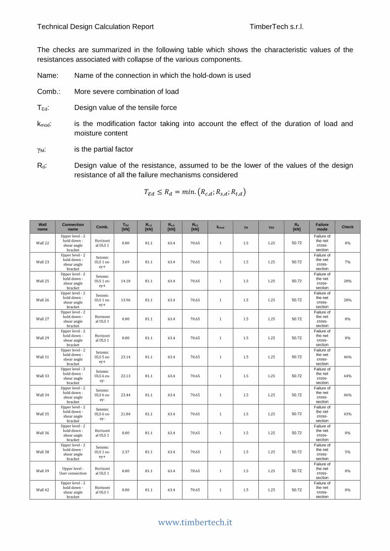
Technical Design Calculation Report TimberTech s.r.l.
www.timbertech.it
The checks are summarized in the following table which shows the characteristic values of the resistances associated with collapse of the various components.
Name: Name of the connection in which the hold-down is used
Comb.: More severe combination of load
TEd: Design value of the tensile force
kmod: is the modification factor taking into account the effect of the duration of load and moisture content
γM: is the partial factor
Rd: Design value of the resistance, assumed to be the lower of the values of the design resistance of all the failure mechanisms considered
𝑇𝑇𝐸𝐸𝑑𝑑 ≤ 𝑅𝑅𝑑𝑑 = 𝑡𝑡𝑎𝑎𝑛𝑛. �𝑅𝑅𝑐𝑐,𝑑𝑑;𝑅𝑅𝑠𝑠,𝑑𝑑;𝑅𝑅𝑡𝑡,𝑑𝑑�
Wall name
Connection name Comb. TEd
[kN] Rc,k [kN]
Rs,k [kN]
Rt,k [kN] kmod γM γM2 Rd
[kN] Failure mode Check
Wall 22
Upper level - 2 hold down - shear angle
bracket
Horizontal ULS 1 0.00 81.1 63.4 70.65 1 1.5 1.25 50.72
Failure of the net cross-section
0%
Wall 23
Upper level - 2 hold down - shear angle
bracket
Seismic ULS 1 ex-
ey+ 3.69 81.1 63.4 70.65 1 1.5 1.25 50.72
Failure of the net cross-section
7%
Wall 25
Upper level - 2 hold down - shear angle
bracket
Seismic ULS 1 ex-
ey+ 14.10 81.1 63.4 70.65 1 1.5 1.25 50.72
Failure of the net cross-section
28%
Wall 26
Upper level - 2 hold down - shear angle
bracket
Seismic ULS 1 ex-
ey+ 13.96 81.1 63.4 70.65 1 1.5 1.25 50.72
Failure of the net cross-section
28%
Wall 27
Upper level - 2 hold down - shear angle
bracket
Horizontal ULS 1 0.00 81.1 63.4 70.65 1 1.5 1.25 50.72
Failure of the net cross-section
0%
Wall 29
Upper level - 2 hold down - shear angle
bracket
Horizontal ULS 1 0.00 81.1 63.4 70.65 1 1.5 1.25 50.72
Failure of the net cross-section
0%
Wall 31
Upper level - 2 hold down - shear angle
bracket
Seismic ULS 5 ex-
ey+ 23.14 81.1 63.4 70.65 1 1.5 1.25 50.72
Failure of the net cross-section
46%
Wall 33
Upper level - 2 hold down - shear angle
bracket
Seismic ULS 6 ex-
ey- 22.13 81.1 63.4 70.65 1 1.5 1.25 50.72
Failure of the net cross-section
44%
Wall 34
Upper level - 2 hold down - shear angle
bracket
Seismic ULS 6 ex-
ey- 23.44 81.1 63.4 70.65 1 1.5 1.25 50.72
Failure of the net cross-section
46%
Wall 35
Upper level - 2 hold down - shear angle
bracket
Seismic ULS 6 ex-
ey- 21.84 81.1 63.4 70.65 1 1.5 1.25 50.72
Failure of the net cross-section
43%
Wall 36
Upper level - 2 hold down - shear angle
bracket
Horizontal ULS 1 0.00 81.1 63.4 70.65 1 1.5 1.25 50.72
Failure of the net cross-section
0%
Wall 38
Upper level - 2 hold down - shear angle
bracket
Seismic ULS 1 ex-
ey+ 2.37 81.1 63.4 70.65 1 1.5 1.25 50.72
Failure of the net cross-section
5%
Wall 39 Upper level - User connection
Horizontal ULS 1 0.00 81.1 63.4 70.65 1 1.5 1.25 50.72
Failure of the net cross-section
0%
Wall 42
Upper level - 2 hold down - shear angle
bracket
Horizontal ULS 1 0.00 81.1 63.4 70.65 1 1.5 1.25 50.72
Failure of the net cross-section
0%

Technical Design Calculation Report TimberTech s.r.l.
www.timbertech.it
Wall 43 Upper level - User connection
Horizontal ULS 1 0.00 81.1 63.4 70.65 1 1.5 1.25 50.72
Failure of the net cross-section
0%
Wall 46
Upper level - 2 hold down - shear angle
bracket
Seismic ULS 5 ex-
ey+ 44.90 81.1 63.4 70.65 1 1.5 1.25 50.72
Failure of the net cross-section
89%
Wall 62
Upper level - 2 hold down - shear angle
bracket
Seismic ULS 5 ex-
ey+ 41.16 81.1 63.4 70.65 1 1.5 1.25 50.72
Failure of the net cross-section
81%
Wall 63
Upper level - 2 hold down - shear angle
bracket
Horizontal ULS 1 0.00 81.1 63.4 70.65 1 1.5 1.25 50.72
Failure of the net cross-section
0%
Wall 73
Upper level - 2 hold down - shear angle
bracket
Seismic ULS 5 ex-
ey+ 16.19 81.1 63.4 70.65 1 1.5 1.25 50.72
Failure of the net cross-section
32%
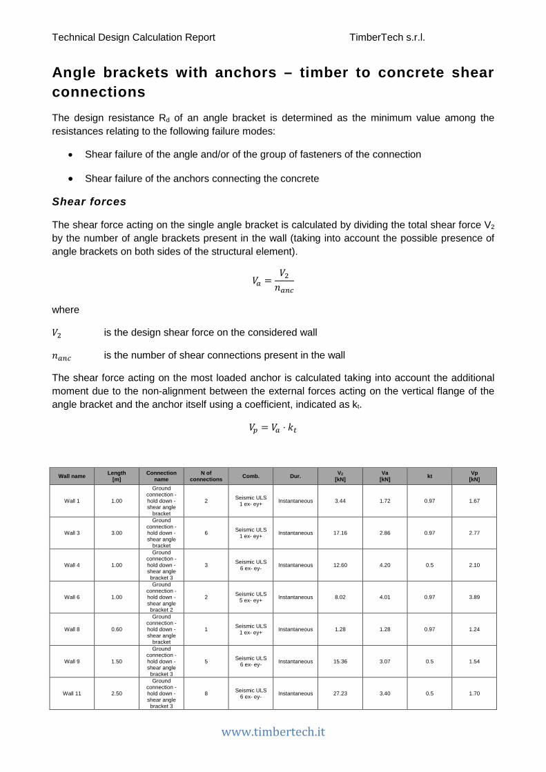
Technical Design Calculation Report TimberTech s.r.l.
www.timbertech.it
Angle brackets with anchors – timber to concrete shear connections
The design resistance Rd of an angle bracket is determined as the minimum value among the resistances relating to the following failure modes:
• Shear failure of the angle and/or of the group of fasteners of the connection
• Shear failure of the anchors connecting the concrete
Shear forces
The shear force acting on the single angle bracket is calculated by dividing the total shear force V2 by the number of angle brackets present in the wall (taking into account the possible presence of angle brackets on both sides of the structural element).
𝑉𝑉𝑚𝑚 =𝑉𝑉2𝑛𝑛𝑚𝑚𝑚𝑚𝑐𝑐
where
𝑉𝑉2 is the design shear force on the considered wall
𝑛𝑛𝑚𝑚𝑚𝑚𝑐𝑐 is the number of shear connections present in the wall
The shear force acting on the most loaded anchor is calculated taking into account the additional moment due to the non-alignment between the external forces acting on the vertical flange of the angle bracket and the anchor itself using a coefficient, indicated as kt.
𝑉𝑉𝑖𝑖 = 𝑉𝑉𝑚𝑚 ⋅ 𝑘𝑘𝑡𝑡
Wall name Length [m]
Connection name
N of connections Comb. Dur. V2
[kN] Va
[kN] kt Vp [kN]
Wall 1 1.00
Ground connection - hold down - shear angle
bracket
2 Seismic ULS 1 ex- ey+ Instantaneous 3.44 1.72 0.97 1.67
Wall 3 3.00
Ground connection - hold down - shear angle
bracket
6 Seismic ULS 1 ex- ey+ Instantaneous 17.16 2.86 0.97 2.77
Wall 4 1.00
Ground connection - hold down - shear angle
bracket 3
3 Seismic ULS 6 ex- ey- Instantaneous 12.60 4.20 0.5 2.10
Wall 6 1.00
Ground connection - hold down - shear angle
bracket 2
2 Seismic ULS 5 ex- ey+ Instantaneous 8.02 4.01 0.97 3.89
Wall 8 0.60
Ground connection - hold down - shear angle
bracket
1 Seismic ULS 1 ex- ey+ Instantaneous 1.28 1.28 0.97 1.24
Wall 9 1.50
Ground connection - hold down - shear angle
bracket 3
5 Seismic ULS 6 ex- ey- Instantaneous 15.36 3.07 0.5 1.54
Wall 11 2.50
Ground connection - hold down - shear angle
bracket 3
8 Seismic ULS 6 ex- ey- Instantaneous 27.23 3.40 0.5 1.70

Technical Design Calculation Report TimberTech s.r.l.
www.timbertech.it
Wall 13 1.50
Ground connection - hold down - shear angle
bracket 3
5 Seismic ULS 6 ex- ey- Instantaneous 15.36 3.07 0.5 1.54
Wall 14 3.00
Ground connection - hold down - shear angle
bracket
6 Seismic ULS 1 ex- ey+ Instantaneous 17.16 2.86 0.97 2.77
Wall 15 2.40
Ground connection - hold down - shear angle
bracket
4 Seismic ULS 2 ex+ ey+ Instantaneous 11.02 2.76 0.97 2.67
Wall 20 7.80
Ground connection - hold down - shear angle
bracket
15 Seismic ULS 2 ex+ ey+ Instantaneous 48.36 3.22 0.97 3.13
Wall 21 2.40
Ground connection - hold down - shear angle
bracket
4 Seismic ULS 2 ex+ ey+ Instantaneous 11.02 2.76 0.97 2.67
Wall 54 2.37
Ground connection - hold down - shear angle
bracket 2
4 Seismic ULS 5 ex- ey+ Instantaneous 30.29 7.57 0.97 7.34
Wall 61 2.80
Ground connection - hold down - shear angle
bracket 4
5 Seismic ULS 6 ex- ey- Instantaneous 34.08 6.82 1 6.82
Wall 66 1.70
Ground connection - hold down - shear angle
bracket 2
3 Seismic ULS 1 ex- ey+ Instantaneous 10.17 3.39 0.97 3.29
Wall 67 1.70
Ground connection - hold down - shear angle
bracket 2
3 Seismic ULS 1 ex- ey+ Instantaneous 10.17 3.39 0.97 3.29
Wall 71 2.50
Ground connection - hold down - shear angle
bracket
5 Seismic ULS 1 ex- ey+ Instantaneous 10.06 2.01 0.97 1.95
Wall 72 3.06
Ground connection - hold down - shear angle
bracket
6 Seismic ULS 1 ex- ey+ Instantaneous 14.68 2.45 0.97 2.37
Wall 72 3.14
Ground connection - hold down - shear angle
bracket
6 Seismic ULS 1 ex- ey+ Instantaneous 15.40 2.57 0.97 2.49
Wall3 2.80
Ground connection - hold down - shear angle
bracket 2
5 Seismic ULS 5 ex- ey+ Instantaneous 31.89 6.38 0.97 6.19
Angle bracket bearing capacity
The design value of the shear bearing capacity of the angle bracket can be estimated from the characteristic value by means of the following expression
𝑅𝑅𝑚𝑚,𝑑𝑑 =𝑘𝑘𝑚𝑚𝑚𝑚𝑑𝑑 ⋅ Ra,k,dens
𝛾𝛾𝑀𝑀
where
Ra,k,dens is the characteristic bearing capacity of the angle bracket, corrected to take account of
the actual density of the material used according to the formula Ra,k,dens = Ra,k ⋅ �ρk350
�2
where Ra,k was evaluated as described in the document ETA-09/0323 for WBR100, as described in the document ETA-09/0324 for WKR095 and WKR135, as described in the document ETA-11/0496 for Titan TCN200, TCN240 and TCF200, or on the basis of the data introduced by the user

Technical Design Calculation Report TimberTech s.r.l.
www.timbertech.it
Anchor bearing capacity
The design value of the shear strength of the anchor is evaluated as
𝑅𝑅𝑖𝑖,𝑑𝑑 =𝑅𝑅𝑖𝑖,𝑘𝑘
𝛾𝛾𝑀𝑀𝑠𝑠,𝑉𝑉
where
𝑅𝑅𝑖𝑖,𝑘𝑘 is the characteristic value of the shear strength of the anchor, calculated according to the indications of the documents ETA-09/0078 e ETA-07/0067
𝛾𝛾𝑀𝑀𝑠𝑠,𝑉𝑉 is the partial safety factor, assumed as reported in the documents ETA-09/0078 e ETA-07/0067
The checks are summarized in the following table which illustrates the characteristic values of the resistances associated to the different components and their design values.
Name: Name of the connection in which the angle bracket is used
Comb.: More severe combination of load
Va,Ed: Shear force
kmod: Modification factor taking into account the effect of the duration of load and moisture content
γM: Partial safety factor
Wall name
Connection
name Comb. Va,Ed
[kN] Ra,k [kN] kmod γM Ra,d
[kN]
Check – angle
brackets
Vp [kN]
Rp,k [kN] γMs,V Rp,d
[kN] Check - anchor
Wall 1
Ground connection - hold down - shear angle
bracket
Seismic ULS 1 ex- ey+
1.72 22.1 1 1.5 14.73 12% 1.67 21 1.25 16.8 10%
Wall 3
Ground connection - hold down - shear angle
bracket
Seismic ULS 1 ex- ey+
2.86 22.1 1 1.5 14.73 19% 2.77 21 1.25 16.8 17%
Wall 4
Ground connection - hold down - shear angle
bracket 3
Seismic ULS 6 ex- ey-
4.20 8.94 1 1.5 5.96 70% 2.10 15 1.25 12 18%
Wall 6
Ground connection - hold down - shear angle
bracket 2
Seismic ULS 5 ex- ey+
4.01 22.1 1 1.5 14.73 27% 3.89 30 1.8 16.67 23%
Wall 8
Ground connection - hold down - shear angle
bracket
Seismic ULS 1 ex- ey+
1.28 22.1 1 1.5 14.73 9% 1.24 21 1.25 16.8 7%

Technical Design Calculation Report TimberTech s.r.l.
www.timbertech.it
Wall 9
Ground connection - hold down - shear angle
bracket 3
Seismic ULS 6 ex- ey-
3.07 8.94 1 1.5 5.96 52% 1.54 15 1.25 12 13%
Wall 11
Ground connection - hold down - shear angle
bracket 3
Seismic ULS 6 ex- ey-
3.40 8.94 1 1.5 5.96 57% 1.70 15 1.25 12 14%
Wall 13
Ground connection - hold down - shear angle
bracket 3
Seismic ULS 6 ex- ey-
3.07 8.94 1 1.5 5.96 52% 1.54 15 1.25 12 13%
Wall 14
Ground connection - hold down - shear angle
bracket
Seismic ULS 1 ex- ey+
2.86 22.1 1 1.5 14.73 19% 2.77 21 1.25 16.8 17%
Wall 15
Ground connection - hold down - shear angle
bracket
Seismic ULS 2
ex+ ey+ 2.76 22.1 1 1.5 14.73 19% 2.67 21 1.25 16.8 16%
Wall 20
Ground connection - hold down - shear angle
bracket
Seismic ULS 2
ex+ ey+ 3.22 22.1 1 1.5 14.73 22% 3.13 21 1.25 16.8 19%
Wall 21
Ground connection - hold down - shear angle
bracket
Seismic ULS 2
ex+ ey+ 2.76 22.1 1 1.5 14.73 19% 2.67 21 1.25 16.8 16%
Wall 54
Ground connection - hold down - shear angle
bracket 2
Seismic ULS 5 ex- ey+
7.57 22.1 1 1.5 14.73 51% 7.34 30 1.8 16.67 44%
Wall 61
Ground connection - hold down - shear angle
bracket 4
Seismic ULS 6 ex- ey-
6.82 30.3 1 1.5 20.2 34% 6.82 37.9 1.5 25.27 27%
Wall 66
Ground connection - hold down - shear angle
bracket 2
Seismic ULS 1 ex- ey+
3.39 22.1 1 1.5 14.73 23% 3.29 30 1.8 16.67 20%
Wall 67
Ground connection - hold down - shear angle
bracket 2
Seismic ULS 1 ex- ey+
3.39 22.1 1 1.5 14.73 23% 3.29 30 1.8 16.67 20%
Wall 71
Ground connection - hold down - shear angle
bracket
Seismic ULS 1 ex- ey+
2.01 22.1 1 1.5 14.73 14% 1.95 21 1.25 16.8 12%
Wall 72
Ground connection - hold down - shear angle
bracket
Seismic ULS 1 ex- ey+
2.45 22.1 1 1.5 14.73 17% 2.37 21 1.25 16.8 14%
Wall 72
Ground connection - hold down -
Seismic ULS 1 ex- ey+
2.57 22.1 1 1.5 14.73 17% 2.49 21 1.25 16.8 15%

Technical Design Calculation Report TimberTech s.r.l.
www.timbertech.it
shear angle
bracket
Wall3
Ground connection - hold down - shear angle
bracket 2
Seismic ULS 5 ex- ey+
6.38 22.1 1 1.5 14.73 43% 6.19 30 1.8 16.67 37%
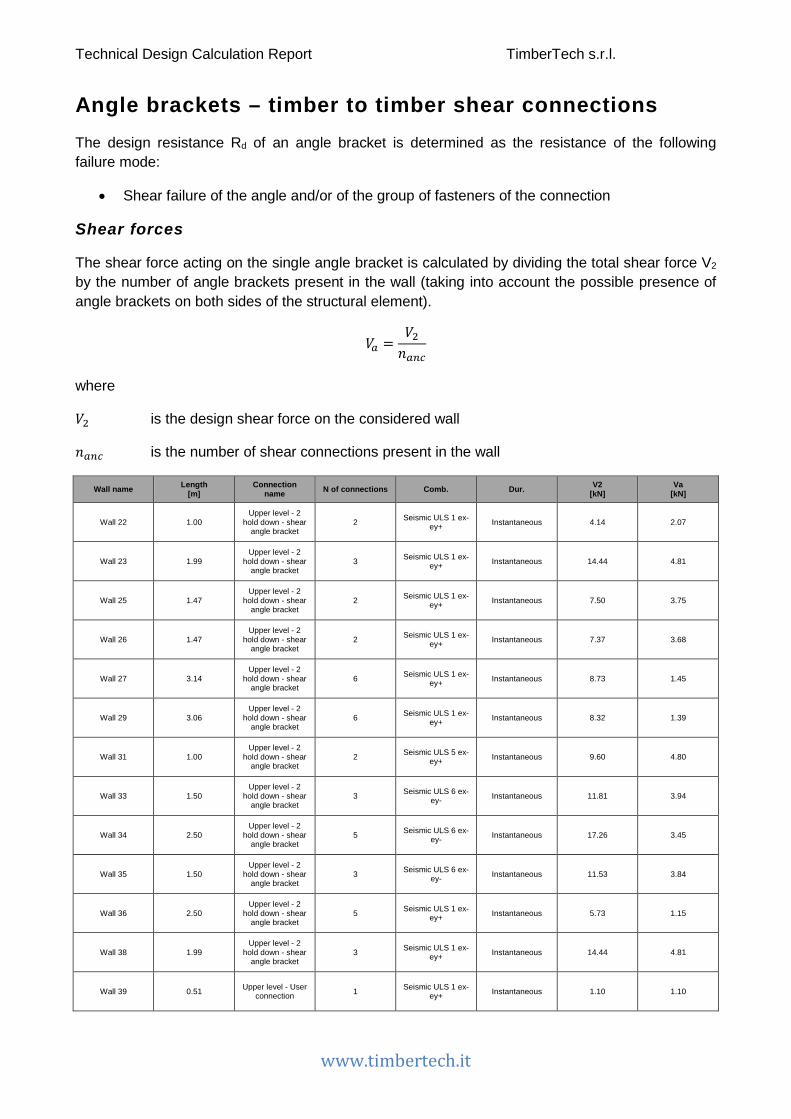
Technical Design Calculation Report TimberTech s.r.l.
www.timbertech.it
Angle brackets – timber to timber shear connections
The design resistance Rd of an angle bracket is determined as the resistance of the following failure mode:
• Shear failure of the angle and/or of the group of fasteners of the connection
Shear forces
The shear force acting on the single angle bracket is calculated by dividing the total shear force V2 by the number of angle brackets present in the wall (taking into account the possible presence of angle brackets on both sides of the structural element).
𝑉𝑉𝑚𝑚 =𝑉𝑉2𝑛𝑛𝑚𝑚𝑚𝑚𝑐𝑐
where
𝑉𝑉2 is the design shear force on the considered wall
𝑛𝑛𝑚𝑚𝑚𝑚𝑐𝑐 is the number of shear connections present in the wall
Wall name Length [m]
Connection name N of connections Comb. Dur. V2
[kN] Va
[kN]
Wall 22 1.00 Upper level - 2
hold down - shear angle bracket
2 Seismic ULS 1 ex- ey+ Instantaneous 4.14 2.07
Wall 23 1.99 Upper level - 2
hold down - shear angle bracket
3 Seismic ULS 1 ex- ey+ Instantaneous 14.44 4.81
Wall 25 1.47 Upper level - 2
hold down - shear angle bracket
2 Seismic ULS 1 ex- ey+ Instantaneous 7.50 3.75
Wall 26 1.47 Upper level - 2
hold down - shear angle bracket
2 Seismic ULS 1 ex- ey+ Instantaneous 7.37 3.68
Wall 27 3.14 Upper level - 2
hold down - shear angle bracket
6 Seismic ULS 1 ex- ey+ Instantaneous 8.73 1.45
Wall 29 3.06 Upper level - 2
hold down - shear angle bracket
6 Seismic ULS 1 ex- ey+ Instantaneous 8.32 1.39
Wall 31 1.00 Upper level - 2
hold down - shear angle bracket
2 Seismic ULS 5 ex- ey+ Instantaneous 9.60 4.80
Wall 33 1.50 Upper level - 2
hold down - shear angle bracket
3 Seismic ULS 6 ex- ey- Instantaneous 11.81 3.94
Wall 34 2.50 Upper level - 2
hold down - shear angle bracket
5 Seismic ULS 6 ex- ey- Instantaneous 17.26 3.45
Wall 35 1.50 Upper level - 2
hold down - shear angle bracket
3 Seismic ULS 6 ex- ey- Instantaneous 11.53 3.84
Wall 36 2.50 Upper level - 2
hold down - shear angle bracket
5 Seismic ULS 1 ex- ey+ Instantaneous 5.73 1.15
Wall 38 1.99 Upper level - 2
hold down - shear angle bracket
3 Seismic ULS 1 ex- ey+ Instantaneous 14.44 4.81
Wall 39 0.51 Upper level - User connection 1 Seismic ULS 1 ex-
ey+ Instantaneous 1.10 1.10

Technical Design Calculation Report TimberTech s.r.l.
www.timbertech.it
Wall 42 7.80 Upper level - 2
hold down - shear angle bracket
15 Seismic ULS 2 ex+ ey+ Instantaneous 50.77 3.38
Wall 43 2.40 Upper level - User connection 4 Seismic ULS 2
ex+ ey+ Instantaneous 6.14 1.53
Wall 46 1.50 Upper level - 2
hold down - shear angle bracket
3 Seismic ULS 5 ex- ey+ Instantaneous 21.03 7.01
Wall 62 2.80 Upper level - 2
hold down - shear angle bracket
5 Seismic ULS 5 ex- ey+ Instantaneous 35.89 7.18
Wall 63 2.40 Upper level - 2
hold down - shear angle bracket
4 Seismic ULS 2 ex+ ey+ Instantaneous 7.11 1.78
Wall 73 1.00 Upper level - 2
hold down - shear angle bracket
2 Seismic ULS 5 ex- ey+ Instantaneous 7.37 3.68
Angle bracket bearing capacity
The design value of the shear strength of the anchor is evaluated as
𝑅𝑅𝑚𝑚,𝑑𝑑 =𝑘𝑘𝑚𝑚𝑚𝑚𝑑𝑑 ⋅ Ra,k,dens
𝛾𝛾𝑀𝑀
where
Ra,k,dens is the characteristic bearing capacity of the angle bracket, corrected to take account of
the actual density of the material used according to the formula Ra,k,dens = Ra,k ⋅ �ρk350
�2
where Ra,k was evaluated as described in the document ETA-09/0323 for WBR100, as described in the document ETA-11/0496 for Titan TCN200, TCN240 and TCF200, or on the basis of the data introduced by the user
𝑘𝑘𝑚𝑚𝑚𝑚𝑑𝑑 is the modification factor taking into account the effect of the duration of load and moisture content
𝛾𝛾𝑀𝑀 is the partial factor for connections
The checks are summarized in the following table which illustrates the characteristic values of the resistance associated to the angle brackets and their design values. The following expression shall be satisfied:
𝑉𝑉𝐸𝐸𝑑𝑑 ≤ 𝑅𝑅𝑚𝑚,𝑑𝑑
Connection name: Name of the connection in which the angle bracket is used
Comb.: More severe combination of load
Va,Ed: Design value of the force acting on the single angular
𝑘𝑘𝑚𝑚𝑚𝑚𝑑𝑑 is the modification factor taking into account the effect of the duration of load and moisture content
𝛾𝛾𝑀𝑀 is the partial factor for connections

Technical Design Calculation Report TimberTech s.r.l.
www.timbertech.it
Wall name Connection name Comb. Va,Ed [kN]
Ra,k [kN] kmod γM Ra,d
[kN] Check
Wall 22 Upper level - 2 hold down - shear angle
bracket
Seismic ULS 1 ex-
ey+ 2.07 37.9 1 1.5 25.27 8%
Wall 23 Upper level - 2 hold down - shear angle
bracket
Seismic ULS 1 ex-
ey+ 4.81 37.9 1 1.5 25.27 19%
Wall 25 Upper level - 2 hold down - shear angle
bracket
Seismic ULS 1 ex-
ey+ 3.75 37.9 1 1.5 25.27 15%
Wall 26 Upper level - 2 hold down - shear angle
bracket
Seismic ULS 1 ex-
ey+ 3.68 37.9 1 1.5 25.27 15%
Wall 27 Upper level - 2 hold down - shear angle
bracket
Seismic ULS 1 ex-
ey+ 1.45 37.9 1 1.5 25.27 6%
Wall 29 Upper level - 2 hold down - shear angle
bracket
Seismic ULS 1 ex-
ey+ 1.39 37.9 1 1.5 25.27 5%
Wall 31 Upper level - 2 hold down - shear angle
bracket
Seismic ULS 5 ex-
ey+ 4.80 37.9 1 1.5 25.27 19%
Wall 33 Upper level - 2 hold down - shear angle
bracket
Seismic ULS 6 ex-
ey- 3.94 37.9 1 1.5 25.27 16%
Wall 34 Upper level - 2 hold down - shear angle
bracket
Seismic ULS 6 ex-
ey- 3.45 37.9 1 1.5 25.27 14%
Wall 35 Upper level - 2 hold down - shear angle
bracket
Seismic ULS 6 ex-
ey- 3.84 37.9 1 1.5 25.27 15%
Wall 36 Upper level - 2 hold down - shear angle
bracket
Seismic ULS 1 ex-
ey+ 1.15 37.9 1 1.5 25.27 5%
Wall 38 Upper level - 2 hold down - shear angle
bracket
Seismic ULS 1 ex-
ey+ 4.81 37.9 1 1.5 25.27 19%
Wall 39 Upper level - User connection
Seismic ULS 1 ex-
ey+ 1.10 10 1 1.5 6.67 16%
Wall 42 Upper level - 2 hold down - shear angle
bracket
Seismic ULS 2 ex+
ey+ 3.38 37.9 1 1.5 25.27 13%
Wall 43 Upper level - User connection
Seismic ULS 2 ex+
ey+ 1.53 10 1 1.5 6.67 23%
Wall 46 Upper level - 2 hold down - shear angle
bracket
Seismic ULS 5 ex-
ey+ 7.01 37.9 1 1.5 25.27 28%
Wall 62 Upper level - 2 hold down - shear angle
bracket
Seismic ULS 5 ex-
ey+ 7.18 37.9 1 1.5 25.27 28%
Wall 63 Upper level - 2 hold down - shear angle
bracket
Seismic ULS 2 ex+
ey+ 1.78 37.9 1 1.5 25.27 7%
Wall 73 Upper level - 2 hold down - shear angle
bracket
Seismic ULS 5 ex-
ey+ 3.68 37.9 1 1.5 25.27 15%
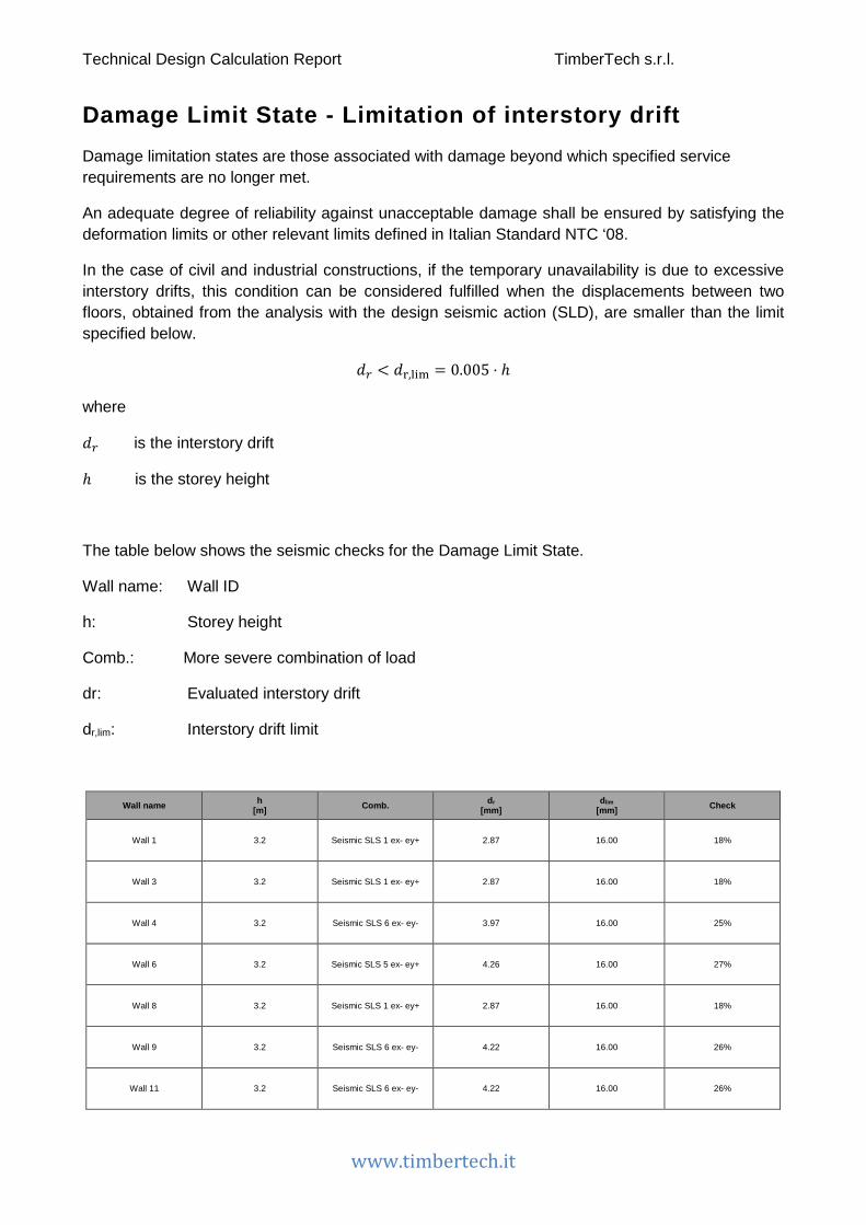
Technical Design Calculation Report TimberTech s.r.l.
www.timbertech.it
Damage Limit State - Limitation of interstory drift Damage limitation states are those associated with damage beyond which specified service requirements are no longer met.
An adequate degree of reliability against unacceptable damage shall be ensured by satisfying the deformation limits or other relevant limits defined in Italian Standard NTC ‘08.
In the case of civil and industrial constructions, if the temporary unavailability is due to excessive interstory drifts, this condition can be considered fulfilled when the displacements between two floors, obtained from the analysis with the design seismic action (SLD), are smaller than the limit specified below.
𝑜𝑜𝑟𝑟 < 𝑜𝑜r,lim = 0.005 ⋅ ℎ
where
𝑜𝑜𝑟𝑟 is the interstory drift
ℎ is the storey height
The table below shows the seismic checks for the Damage Limit State.
Wall name: Wall ID
h: Storey height
Comb.: More severe combination of load
dr: Evaluated interstory drift
dr,lim: Interstory drift limit
Wall name h [m] Comb. dr
[mm] dlim
[mm] Check
Wall 1 3.2 Seismic SLS 1 ex- ey+ 2.87 16.00 18%
Wall 3 3.2 Seismic SLS 1 ex- ey+ 2.87 16.00 18%
Wall 4 3.2 Seismic SLS 6 ex- ey- 3.97 16.00 25%
Wall 6 3.2 Seismic SLS 5 ex- ey+ 4.26 16.00 27%
Wall 8 3.2 Seismic SLS 1 ex- ey+ 2.87 16.00 18%
Wall 9 3.2 Seismic SLS 6 ex- ey- 4.22 16.00 26%
Wall 11 3.2 Seismic SLS 6 ex- ey- 4.22 16.00 26%
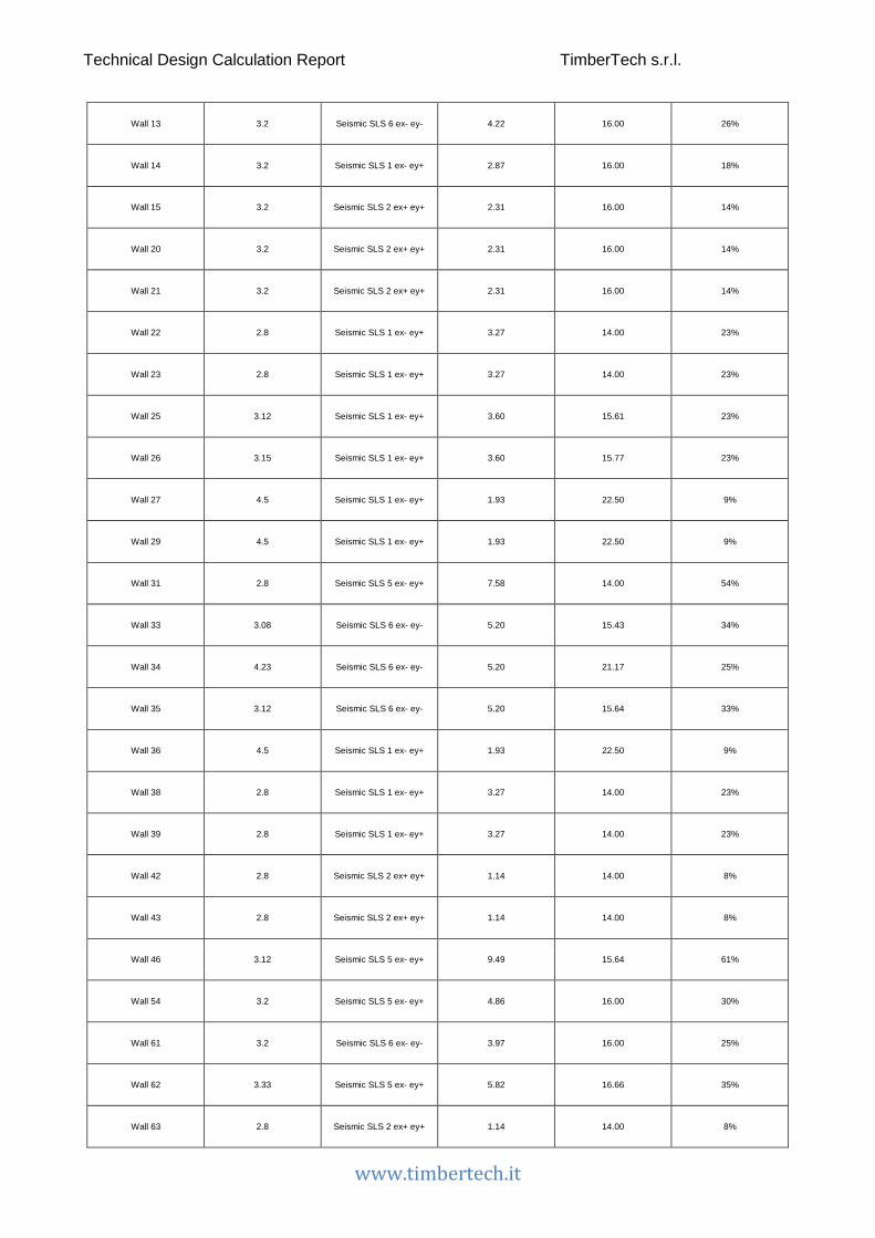
Technical Design Calculation Report TimberTech s.r.l.
www.timbertech.it
Wall 13 3.2 Seismic SLS 6 ex- ey- 4.22 16.00 26%
Wall 14 3.2 Seismic SLS 1 ex- ey+ 2.87 16.00 18%
Wall 15 3.2 Seismic SLS 2 ex+ ey+ 2.31 16.00 14%
Wall 20 3.2 Seismic SLS 2 ex+ ey+ 2.31 16.00 14%
Wall 21 3.2 Seismic SLS 2 ex+ ey+ 2.31 16.00 14%
Wall 22 2.8 Seismic SLS 1 ex- ey+ 3.27 14.00 23%
Wall 23 2.8 Seismic SLS 1 ex- ey+ 3.27 14.00 23%
Wall 25 3.12 Seismic SLS 1 ex- ey+ 3.60 15.61 23%
Wall 26 3.15 Seismic SLS 1 ex- ey+ 3.60 15.77 23%
Wall 27 4.5 Seismic SLS 1 ex- ey+ 1.93 22.50 9%
Wall 29 4.5 Seismic SLS 1 ex- ey+ 1.93 22.50 9%
Wall 31 2.8 Seismic SLS 5 ex- ey+ 7.58 14.00 54%
Wall 33 3.08 Seismic SLS 6 ex- ey- 5.20 15.43 34%
Wall 34 4.23 Seismic SLS 6 ex- ey- 5.20 21.17 25%
Wall 35 3.12 Seismic SLS 6 ex- ey- 5.20 15.64 33%
Wall 36 4.5 Seismic SLS 1 ex- ey+ 1.93 22.50 9%
Wall 38 2.8 Seismic SLS 1 ex- ey+ 3.27 14.00 23%
Wall 39 2.8 Seismic SLS 1 ex- ey+ 3.27 14.00 23%
Wall 42 2.8 Seismic SLS 2 ex+ ey+ 1.14 14.00 8%
Wall 43 2.8 Seismic SLS 2 ex+ ey+ 1.14 14.00 8%
Wall 46 3.12 Seismic SLS 5 ex- ey+ 9.49 15.64 61%
Wall 54 3.2 Seismic SLS 5 ex- ey+ 4.86 16.00 30%
Wall 61 3.2 Seismic SLS 6 ex- ey- 3.97 16.00 25%
Wall 62 3.33 Seismic SLS 5 ex- ey+ 5.82 16.66 35%
Wall 63 2.8 Seismic SLS 2 ex+ ey+ 1.14 14.00 8%
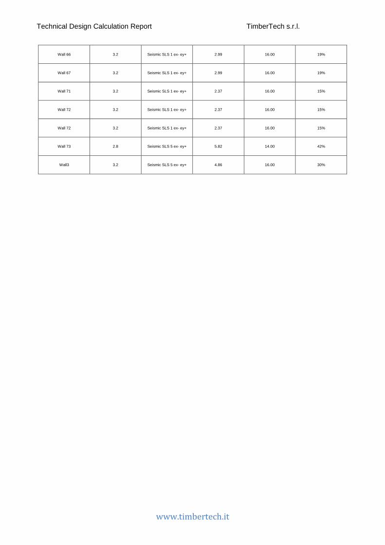
Technical Design Calculation Report TimberTech s.r.l.
www.timbertech.it
Wall 66 3.2 Seismic SLS 1 ex- ey+ 2.99 16.00 19%
Wall 67 3.2 Seismic SLS 1 ex- ey+ 2.99 16.00 19%
Wall 71 3.2 Seismic SLS 1 ex- ey+ 2.37 16.00 15%
Wall 72 3.2 Seismic SLS 1 ex- ey+ 2.37 16.00 15%
Wall 72 3.2 Seismic SLS 1 ex- ey+ 2.37 16.00 15%
Wall 73 2.8 Seismic SLS 5 ex- ey+ 5.82 14.00 42%
Wall3 3.2 Seismic SLS 5 ex- ey+ 4.86 16.00 30%