technical data - viking group inc · technical data describing the viking deluge valve and other...
TRANSCRIPT
TECHNICAL DATA
January 27, 2012
DoubLE INTErLoCkED prEACTIoN sysTEm
wITH ELECTrIC/ pNEu-LECTrIC rELEAsE
The Viking Corporation, 210 N Industrial park Drive, Hastings mI 49058Telephone: 269-945-9501 Technical services: 877-384-5464 Fax: 269-818-1680 Email: [email protected]
321a
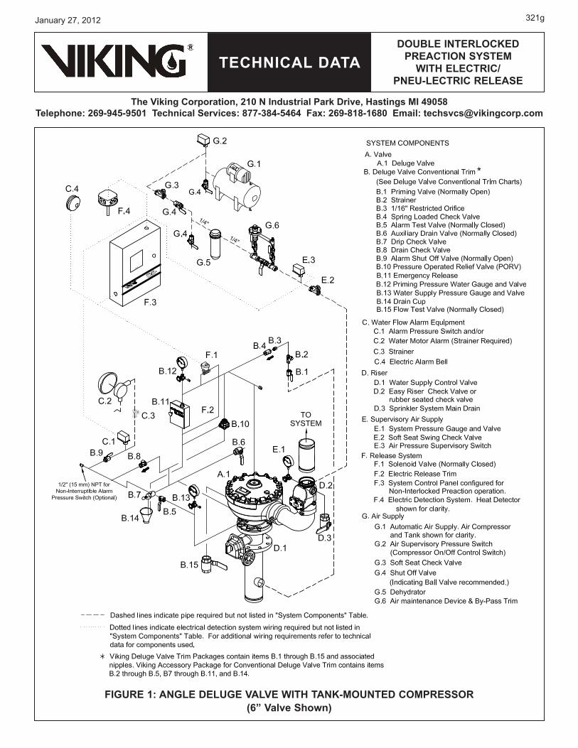
1. DEsCrIpTIoNDEsCrIpTIoN(Refer to Figures 1-6.)Viking Electric/Pneu-Lectric Double Interlocked Preaction Systems utilize a Viking deluge valve, pneumatic supervision of the auto-matic sprinkler system, and an electric detection system. The deluge valve release trim utilizes a normally closed electric solenoid valve controlled by an approved release control panel with two initiating circuits configured for “cross-zoned” operation. One initiating circuit is connected to the electric detection system; the other to a “low-air” supervisory switch.BOTH the electric detection system must activate AND supervisory air pressure must be relieved from the sprinkler system before the deluge valve will open to fill the sprinkler system with water. If the electric detection system (alone) operates, an alarm will activate but the deluge valve will NOT open. If the sprinkler piping is damaged or a sprinkler is broken or fused, but the detection system has not activated, an alarm will activate, but the deluge valve will NOT open.In fire conditions, after both the detection system and a sprinkler operate, the deluge valve opens, allowing water to enter the system. Electric/pneu-lectric double iInterlocked preaction systems are commonly used as refrigerated area systems. They are also commonly used where flooding of the sprinkler system piping can have serious consequences and where it is important to control accidental water discharge due to damaged sprinkler piping.
2. LIsTINgs AND ApproVALsFm Approved: Viking Electric/Pneu-Lectric Double-Interlocked Preaction Systems are Factory Mutual (FM) Approved as refrig-erated area systems when installed with specific components. Refer to the current FM Approval Guide. Consult the manufac-turer for any component approvals too recent to appear in the FM Approval Guide.
3. sysTEm opErATIoN(Refer to Figures 1-6.) A. IN THE sET CoNDITIoN
System water supply pressure enters the priming chamber of the deluge valve through the 1/4” (8 mm) priming line, which includes a normally open priming valve (B.1), strainer (B.2), restricted orifice (B.3), and check valve (B.4). In the SET condition, water sup-ply pressure is trapped in the priming chamber by check valve and normally closed solenoid valve (F.1). The water supply pres-sure trapped in the priming chamber holds the deluge valve clapper closed, keeping the outlet chamber and system piping dry.
b. IN FIrE CoNDITIoNsIn a fire condition, operation of the detection system (F.4) activates the first initiating circuit in the system control panel (F.3), causing an alarm to activate. When a sprinkler operates, air pressure escapes from the sprinkler piping. The air supervisory switch (E.3) activates the second initiating circuit in system control panel. When BOTH initiating circuits have been activated, the system control panel energizes the solenoid valve (F.1) open. Pressure is released from the priming chamber to the open drain cup faster than it is supplied through the restricted orifice. The deluge valve (A.1) clapper opens to allow water to flow into the system piping and alarm(A.1) clapper opens to allow water to flow into the system piping and alarmclapper opens to allow water to flow into the system piping and alarm devices, causing the water motor alarm (C.2) and water flow alarms connected to the alarm pressure switch (C.1) to activate.An optional accelerator may be installed to provide earlier alarms and/or allow the system to fill with water faster. An accelerator may be necessary to meet system water delivery time requirements. When the deluge valve (A.1) operates, the sensing end of the PORV (B.1�) is pressurized, causing the PORV (B.1�) to operate.(A.1) operates, the sensing end of the PORV (B.1�) is pressurized, causing the PORV (B.1�) to operate.operates, the sensing end of the PORV (B.1�) is pressurized, causing the PORV (B.1�) to operate.(B.10) to operate.to operate. When the PORV (B.1�) operates, it continually vents the priming chamber to prevent the deluge valve (A.1) from resetting even(B.1�) operates, it continually vents the priming chamber to prevent the deluge valve (A.1) from resetting evenoperates, it continually vents the priming chamber to prevent the deluge valve (A.1) from resetting even(A.1) from resetting evenfrom resetting even if the solenoid valve (F.1) closes. The deluge valve (A.1) can only be reset after the system is taken out of service, and the outlet(A.1) can only be reset after the system is taken out of service, and the outletcan only be reset after the system is taken out of service, and the outlet chamber of the deluge valve (A.1) and associated trim piping are depressurized and drained.(A.1) and associated trim piping are depressurized and drained.and associated trim piping are depressurized and drained.
C. TroubLE CoNDITIoNsIf a sprinkler opens prior to operation of the detection system, or any time supervisory pressure in the sprinkler piping is lost, alarms connected to air supervisory switch (E.3) will signal a low-air pressure condition, but the deluge valve will NOT open. If the electric detection system (alone) operates (F.4) due to damage or malfunction, alarms connected to the system control panel (F.3) will activate, but the deluge valve (A.1) will NOT open.(A.1) will NOT open.will NOT open.
D. mANuAL opErATIoNAny time the handle inside the emergency release (B.11) is pulled, pressure is released from the priming chamber; the deluge valve (A.1) will open. Water will flow into the system piping and alarm devices. If a sprinkler head opens, water will flow from the system.will open. Water will flow into the system piping and alarm devices. If a sprinkler head opens, water will flow from the system.
4. INsTALLATIoNrefer to current Viking Technical Data describing individual components of the Viking Electric/Pneu-Lectric Double-Interlocked Pre-action System. Technical Data describing the Viking Deluge Valve and other system components are packed with product and in the Viking Engineering and Design Data book. Also, refer to applicable installation standards, codes, and Authorities Having Jurisdiction.A. ImporTANT sETTINgs
(Also refer to Table 1 above.)1. Recommended pneumatic supervisory pressure in the closed sprinkler piping is 30 PSI (2.1 bar). The air supervisory switch
(E.3) should be equipped with two sets of independently adjustable contacts. Use Viking Pressure Supervisory Switch Part Number �9473 (or equal) as air supervisory switch.
Form No. F_�2�195 Replaces page 321a-l, dated October 3, 2��8. (Updated for the new PORV, new Pressure Supervisory Switch, and VFR-4�� Release Control Panel Part Nos.)
TECHNICAL DATA
January 27, 2012
DoubLE INTErLoCkED prEACTIoN sysTEm
wITH ELECTrIC/ pNEu-LECTrIC rELEAsE
The Viking Corporation, 210 N Industrial park Drive, Hastings mI 49058Telephone: 269-945-9501 Technical services: 877-384-5464 Fax: 269-818-1680 Email: [email protected]
321b
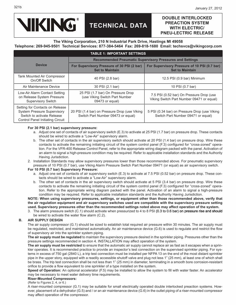
For 30 psI (2.1 bar) supervisory pressure:Adjust one set of contacts of air supervisory switch (E.3) to activate at 25 PSI (1.7 bar) on pressure drop. These contacts should be wired to activate a “Low-Air” supervisory alarm.The other set of contacts in the air supervisory switch should activate at 20 PSI (1.4 bar) on pressure drop. Wire these contacts to activate the remaining initiating circuit of the system control panel (F.3) configured for “cross-zoned” opera-tion. For the VFR-4�� Release Control Panel, refer to the appropriate wiring diagram packed with the panel. Activation of an alarm to signal a high-pressure condition may be required. Refer to applicable installation standards and the Authority Having Jurisdiction.
2. Installation Standards may allow supervisory pressures lower than those recommended above. For pneumatic supervisory pressure of 1� PSI (�.7 bar), use Viking Alarm Pressure Switch Part Number �9471 (or equal) as air supervisory switch.
For 10 psI (0.7 bar) supervisory pressure:Adjust one set of contacts of air supervisory switch (E.3) to activate at 7.5 PSI (�.52 bar) on pressure drop. These con-tacts should be wired to activate a “Low-Air” supervisory alarm.The other set of contacts in the air supervisory switch should activate at 5 PSI (3.4 bar) on pressure drop. Wire these contacts to activate the remaining initiating circuit of the system control panel (F.3) configured for “cross-zoned” opera-tion. Refer to the appropriate wiring diagram packed with the panel. Activation of an alarm to signal a high-pressure condition may be required. Refer to applicable installation standards and the Authority Having Jurisdiction.
NoTE: when using supervisory pressures, settings, or equipment other than those recommended above, verify that the air regulation equipment and air supervisory switches used are compatible with the supervisory pressure setting used. supervisory pressures other than the recommended settings noted above may affect operation of the system.3. The alarm pressure switch (C.1) should activate when pressurized to 4 to 8 PSI (�.3 to �.�� bar) on pressure rise and should(0.3 to 0.6 bar) on pressure rise and should on pressure rise and should
be wired to activate the water flow alarm (C.2). b. AIr suppLy DEsIgN
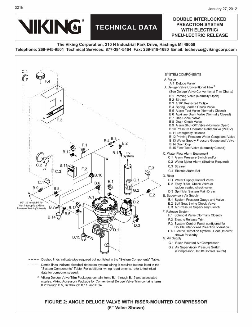
The air supply compressor (G.1) should be sized to establish total required air pressure within 3� minutes. The air supply must be regulated, restricted, and maintained automatically. An air maintenance device (G.��) is used to regulate and restrict the flow of supervisory air into the sprinkler system piping.The air supply must be regulated to maintain the supervisory pressure desired in the sprinkler piping. Pressures other than the pressure settings recommended in section 4. INSTALLATION may affect operation of the system.The air supply must be restricted to ensure that the automatic air supply cannot replace air as fast as it escapes when a sprin-kler operates. It is recommended practice to provide an inspector’s test connection on the supervised sprinkler piping. For sys-tems in excess of 75� gal (284� L), a trip test connection must be installed per NFPA 13 on the end of the most distant sprinkler pipe in the upper story, equipped with a readily accessible shutoff valve and plug not less 1” (25 mm), al least one of which shall be brass. The trip test connection shall be not less than 1” (25 mm) in diameter, terminating in a smooth bore corrosion-resistant orifice to provide a flow equivalent to one sprinkler of a type installed on the system.speed of operation: An optional accelerator (F.5) may be installed to allow the system to fill with water faster. An accelerator may be necessary to meet water delivery time requirements.riser-mounted Compressors: (Refer to Figures 2, 4, or 6.)A riser-mounted compressor (G.1) may be suitable for small electrically operated double interlocked preaction systems. How-ever, placement of a dehydrator (G.5) and / or an air maintenance device (G.��) in the outlet piping of a riser-mounted compressor may affect operation of the compressor.
a.
b.
a.
b.
TAbLE 1: ImporTANT sETTINgs
Devicerecommended pneumatic supervisory pressures and settings
For supervisory pressure of 30 psI (2 bar) set to maintain
For supervisory pressure of 10 psI (0.7 bar) set to maintain
Tank Mounted Air Compressor On/Off Switch 4� PSI (2.8 bar) 12.5 PSI (�.9 bar) Minimum
Air Maintenance Device 30 PSI (2.1 bar) 10 PSI (0.7 bar)
Low-Air Alarm Contact Setting on Release System Pressure
Supervisory Switch
25 PSI (1.7 bar) On Pressure Drop (use Viking Switch Part Number
�9473 or equal)
7.5 PSI (�.52 bar) On Pressure Drop (use Viking Switch Part Number �9471 or equal)
Setting for Contacts on Release System Pressure Supervisory
Switch to activate Release Control Panel Initiating Circuit
20 PSI (1.4 bar) on Pressure Drop (use Viking Switch Part Number �9473 or equal)
5 PSI (�.34 bar) on Pressure Drop (use Viking Switch Part Number �9471 or equal)
TECHNICAL DATA
January 27, 2012
DoubLE INTErLoCkED prEACTIoN sysTEm
wITH ELECTrIC/ pNEu-LECTrIC rELEAsE
The Viking Corporation, 210 N Industrial park Drive, Hastings mI 49058Telephone: 269-945-9501 Technical services: 877-384-5464 Fax: 269-818-1680 Email: [email protected]
321c
1. When a dehydrator is not installed, verify that the installation is located in a dry environment (not humid) and that the super-vised sprinkler piping is never subject to freezing.
2. When an air maintenance device is not used, verify that the air supply produced is properly “regulated” and “restricted”. See Air Supply Design paragraphs above, and section 7. INSPECTIONS AND TESTS.
3. DO NOT install an accelerator on the system.4. Verify system approval. Refer to the Authority Having Jurisdiction.
5. pLACINg THE sysTEm IN sErVICE(Refer to Figures 1-6.)NoTE: rEFEr To INsTruCTIoNs proVIDED IN TECHNICAL DATA DEsCrIbINg THE VIkINg DELugE VALVE AND oTHEr sysTEm CompoNENTs (sEE sECTIoN 8).placing the system to service:
1. Verify that the system has been properly drained. The system main drain and auxiliary drain should be open. Verify that the emergency release (B.11) is closed.
2. Close the system main drain (D.3).3. Restore supervisory pressure to sprinkler piping. 4. Establish a normal condition on the release control panel F.3).
Verify that the ½” valve in the air maintenance device by-pass trim (G.��) is closed and that both 1/4” valves are open. 5. Open the priming valve (B.1).��. Open the flow test valve (B.15).7. Partially open the main water supply control valve (D.1).8. When full flow develops from the flow test valve, close the flow test valve (B.15).
Verify that there is no flow from the open auxiliary drain (B.6). 9. Fully open and secure the main water supply control valve (D.1).
1�. Verify that the alarm shut-off valve (B.9) is open and that all other valves are in their normal operating position.11. Depress the plunger of the drip check (B.7). No water should flow from the drip check when the plunger is pushed.
6. EmErgENCy INsTruCTIoNs(Refer to Figures 1-6.)
To Take system out of service:After a fire, verify that the fire is OUT and that placing the system out of service has been authorized by the appropriate Authority Hav-ing Jurisdiction.
1. Close the water supply valve (D.1).2. Open the system main drain (D.3).3. Silence alarms (optional).
To silence electric alarms controlled by the Viking VFR-4�� Release Control Panel (F.3), open the panel and press “ALARM SILENCE”To silence electric alarms controlled by the pressure switch (C.1) and to silence the water motor alarm (C.2), close the alarm shut-off valve (B.9).
NoTE: ELECTrIC ALArms CoNTroLLED by A prEssurE swITCH (g.2) INsTALLED IN THE ½” (15 mm) NpT CoNNEC-TIoN For A NoN-INTErrupTIbLE ALArm prEssurE swITCH CANNoT bE sHuT oFF uNTIL THE DELugE VALVE Is rEsET or TAkEN ouT oF sErVICE.
4. Shut off the air supply (optional) (G.4).5. Open the auxiliary drain (B.��).
NoTE: sprINkLEr sysTEms THAT HAVE bEEN subjECTED To A FIrE musT bE rETurNED To sErVICE As sooN As possIbLE. THE ENTIrE sysTEm musT bE INspECTED For DAmAgE, AND rEpAIrED or rEpLACED As NECEssAry.
6. Replace any detectors that have been damaged. 7. Replace any sprinklers that have opened, that have been damaged, or have been exposed to fire conditions.
a.
a.
a.
b.
Any system maintenance that involves placing a control valve or detection system out of service will impair the fire protection capa-bilities of that system. Prior to proceeding, appropriate impairment procedures per NFPA 25 shall be followed with the notification of all Authorities Having Jurisdiction. Consideration should be given to employment of a fire patrol in the affected areas.
Failure to follow these instructions could cause improper system operation, resulting in serious personal injury and/or property damage.
TECHNICAL DATA
January 27, 2012
DoubLE INTErLoCkED prEACTIoN sysTEm
wITH ELECTrIC/ pNEu-LECTrIC rELEAsE
The Viking Corporation, 210 N Industrial park Drive, Hastings mI 49058Telephone: 269-945-9501 Technical services: 877-384-5464 Fax: 269-818-1680 Email: [email protected]
321d
8. Perform all maintenance procedures recommended in technical data describing individual components of the system that has operated.
9. Return the system to service as soon as possible. Refer to section 5. PLACING THE SYSTEM IN SERVICE.7. INspECTIoNs AND TEsTs
NoTICE: THE owNEr Is rEspoNsIbLE For mAINTAININg THE FIrE proTECTIoN sysTEm AND DEVICEs IN propEr opErATINg CoNDITIoN.
It is imperative that the system be inspected and tested on a regular basis in accordance with NFPA 25. Refer to INSPECTIONS and TESTS recommended in current Viking Technical Data describing individual components of the Viking Electric/Pneu-Lectric Double-Interlocked Preaction System used. (See section 8 for hyperlinks to Viking Technical Data.)The frequency of the inspections may vary due to contaminated water supplies, corrosive water supplies, corrosive atmospheres, as well as the condition of the air supply to the system. For minimum maintenance and inspection requirements, refer to NFPA 25. In addi-tion, the Authority Having Jurisdiction may have additional maintenance, testing, and inspection requirements that must be followed.
Any system maintenance that involves placing a control valve or detection system out of service will impair the fire protection capabilities of that system. Prior to proceeding, appropriate impairment procedures per NFPA 25 shall be followed with the notification of all Authorities Having Jurisdiction. Consideration should be given to employment of
a fire patrol in the affected areas.Failure to follow these instructions could cause improper system operation, resulting in serious personal injury and/or prop-erty damage.Low Air pressure Alarm Test:Quarterly testing of low air alarms is recommended. To Test sprinkler system “Low supervisory Air” Alarm:
1. To prevent operation of the deluge valve and filling the system with water during the test, DO NOT operate the electric de-tection system during this test. Consider closing the main water supply control valve (D.1).
2. Fully open the sprinkler system trip test connection to simulate operation of a sprinkler.3. Verify that low-air alarms operate within an acceptable time period and continue without interruption.4. Close the trip test connection valve.5. Establish pneumatic supervisory pressure to be maintained. Refer to section 4. INSTALLATION.��. Open the system control panel (F.3) and press RESET. Alarms should stop.when testing is complete, return the system to service following steps 1 through 9 below. CAuTIoN! This procedure applies only when done in conjunction with “Low Air” alarm testing described above. If the main water supply valve (D.1) was closed in step 1 above, proceed with steps 1 through 9 below. 1. Verify that the pressure indicated on the priming pressure water gauge (B.12) indicates that the priming chamber is pres-
surized with system water supply pressure.2. Depress the plunger of the drip check (B.7). No water should flow from the drip check when the plunger is pushed.If the main water supply control valve (D.1) was NOT closed in step 1, proceed to step 8 below.If the main water supply control valve WAS closed in step 1, proceed with steps 3 through 9 below.3. Open the flow test valve (B.15) and auxiliary drain.4. Partially open the main water supply control valve (D.1).5. When full flow develops from the flow test valve, close the flow test valve.
Verify that there is no flow from the open auxiliary drain (B.6). ��. Close the auxiliary drain.7. Fully open and secure the main water supply control valve (D.1).8. Verify that the alarm shut-off valve (B.9) is open and that all other valves are in their normal operating position.9. Depress the plunger of the drip check (B.7). No water should flow from the drip check when the plunger is pushed.
Full Flow Trip Test:Performance of a trip test is recommended annually during warm weather. Consider coordinating this test with operation testing of the detectors.CAuTIoN! performance of this test will cause the deluge valve to open and the sprinkler system to fill with water.To Trip Test the Electrically Controlled Double-Interlocked preaction system:
1. Notify the Authority Having Jurisdiction and those in the area affected by the test.2. Trip the deluge valve:
Operate a detector according to the manufacturer’s instructions.Open the sprinkler system inspector’s test connection.
3. The deluge valve should open, filling the sprinkler system with water. Waterflow alarms should operate.
4. Verify adequate flow from the sprinkler system inspector’s test valve within an acceptable time period.
a.
a.b.
a.
TECHNICAL DATA
January 27, 2012
DoubLE INTErLoCkED prEACTIoN sysTEm
wITH ELECTrIC/ pNEu-LECTrIC rELEAsE
The Viking Corporation, 210 N Industrial park Drive, Hastings mI 49058Telephone: 269-945-9501 Technical services: 877-384-5464 Fax: 269-818-1680 Email: [email protected]
321e
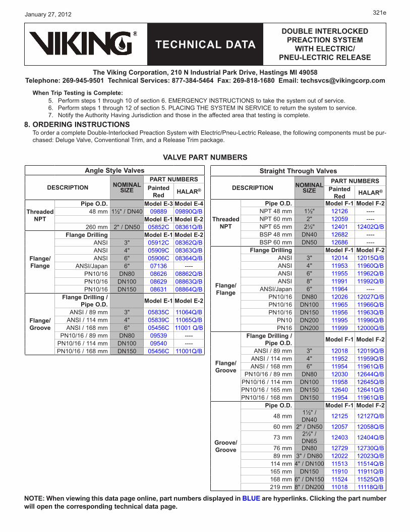
when Trip Testing is Complete:5. Perform steps 1 through 1� of section ��. EMERGENCY INSTRUCTIONS to take the system out of service. ��. Perform steps 1 through 12 of section 5. PLACING THE SYSTEM IN SERVICE to return the system to service.7. Notify the Authority Having Jurisdiction and those in the affected area that testing is complete.
8. orDErINg INsTruCTIoNsTo order a complete Double-Interlocked Preaction System with Electric/Pneu-Lectric Release, the following components must be pur-chased: Deluge Valve, Conventional Trim, and a Release Trim package.
Angle style Valves
DEsCrIpTIoN NomINALsIZE
pArT NumbErspainted
red HALAr®
Threaded NpT
pipe o.D. model E-3 model E-448 mm 1½" / DN4� �9889 �989�Q/B
model E-1 model E-2260 mm 2" / DN5� �5852C �83��1Q/B
Flange/Flange
Flange Drilling model E-1 model E-2ANSI 3" �5912C �83��2Q/BANSI 4" �59�9C �83��3Q/BANSI 6" �59���C �83��4Q/B
ANSI/Japan 6" 07136 ----PN1�/1�� DN8� �8��26 �88��2Q/BPN1�/1�� DN1�� �8��29 �88��3Q/BPN1�/1�� DN15� �8��31 �88��4Q/B
Flange/groove
Flange Drilling / pipe o.D. model E-1 model E-2
ANSI / 89 mm 3" �5835C 11064Q/BANSI / 114 mm 4" �5839C 11���5Q/BANSI / 1��8 mm 6" �545��C 11001 Q/B
PN1�/1�� / 89 mm DN8� �9539 ----PN1�/1�� / 114 mm DN1�� �9540 ----PN1�/1�� / 1��8 mm DN15� �545��C 11001Q/B
straight Through Valves
DEsCrIpTIoN NomINALsIZE
pArT NumbErspainted
red HALAr®
Threaded NpT
pipe o.D. model F-1 model F-2 NPT 48 mm 1½" 12126 ----NPT ��� mm 2" 12�59 ----NPT ��5 mm 2½" 12401 12402Q/BBSP 48 mm DN4� 12��82 ----BSP 60 mm DN5� 12��86 ----
Flange/Flange
Flange Drilling model F-1 model F-2ANSI 3" 12014 12�15Q/BANSI 4" 11953 119���Q/BANSI 6" 11955 119��2Q/BANSI 8" 11991 11992Q/B
ANSI/Japan 6" 119��4 ----PN1�/1�� DN8� 12026 12027Q/BPN1�/1�� DN1�� 119��5 119����Q/BPN1�/1�� DN15� 11956 119��3Q/B
PN1� DN2�� 11995 1199��Q/BPN1�� DN2�� 11999 12000Q/B
Flange/groove
Flange Drilling / pipe o.D. model F-1 model F-2
ANSI / 89 mm 3" 12018 12�19Q/BANSI / 114 mm 4" 11952 11959Q/BANSI / 1��8 mm 6" 11954 119��1Q/B
PN1�/1�� / 89 mm DN8� 12030 12644Q/BPN1�/1�� / 114 mm DN1�� 11958 12��45Q/BPN1�/1�� / 1��5 mm DN15� 12640 12641Q/BPN1�/1�� / 1��8 mm DN15� 11954 119��1Q/B
groove/groove
pipe o.D. model F-1 model F-2
48 mm 1½" / DN4� 12125 12127Q/B
60 mm 2" / DN5� 12�57 12�58Q/B
73 mm 2½" / DN��5 12403 12404Q/B
76 mm DN8� 12729 12730Q/B89 mm 3" / DN8� 12022 12023Q/B
114 mm 4" / DN1�� 11513 11514Q/B1��5 mm DN15� 11910 11911Q/B1��8 mm ��" / DN15� 11524 11525Q/B219 mm 8" / DN2�� 11018 11118Q/B
VALVE pArT NumbErs
NoTE: when viewing this data page online, part numbers displayed in bLuE are hyperlinks. Clicking the part number will open the corresponding technical data page.
TECHNICAL DATA
January 27, 2012
DoubLE INTErLoCkED prEACTIoN sysTEm
wITH ELECTrIC/ pNEu-LECTrIC rELEAsE
The Viking Corporation, 210 N Industrial park Drive, Hastings mI 49058Telephone: 269-945-9501 Technical services: 877-384-5464 Fax: 269-818-1680 Email: [email protected]
321f
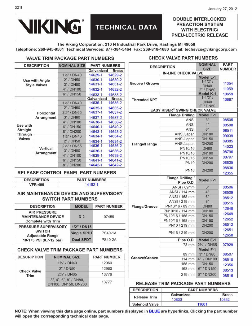
DEsCrIpTIoN NomINAL sIZE pArT NumbErs
use with Angle style Valves
galvanized brass1½" / DN4� 14��29-1 14��29-22" / DN5� 14630-1 14630-23" / DN8� 14631-1 14631-2
14632-1 14632-214633-1 14633-2
4" / DN1����" / DN15�
use with straight Through Valves
Horizontal Arrangment
galvanized brass1½" / DN4� 14��35-1 14��35-2
14��35-1 14��35-22" / DN5�2½" / DN��5 14637-1 14637-2
14637-1 14637-23" / DN8�4" / DN1�� 14��38-1 14��38-2��" / DN15� 14640-1 14640-28" / DN2�� 14643-1 14643-2
Vertical Arrangment
1½" / DN4� 14634-1 14634-214634-1 14634-22" / DN5�
2½" / DN��5 14636-1 14636-214636-1 14636-23" / DN8�
4" / DN1�� 14��39-1 14��39-2��" / DN15� 14641-1 14641-28" / DN2�� 14642-1 14642-2
CHECk VALVE pArT NumbErs
DEsCrIpTIoN NomINAL sIZE pArT NumbEr
Check Valve Trim
1½" / DN4� 129���2" / DN5� 129���
2½" / DN��5 137763", 4”, ��”, 8” / DN8�,
DN1��, DN15�, DN2�� 13777
DEsCrIpTIoN moDEL pArT NumbErAIr prEssurE
mAINTENANCE DEVICE Complete with Trim
D-2 �7459
prEssurE supErVIsory swITCH
Adjustable range 10-175 psI (0.7-12 bar)
1/2” / DN15single spDT PS4�-1A
Dual spDT PS4�-2A
AIr mAINTENANCE DEVICE AND supErVIsory swITCH pArT NumbErs
DEsCrIpTIoN pArT NumbErs
release Trim galvanized brass 1�83� 1�832
solenoid Valve 11601
DEsCrIpTIoN pArT NumbErsVFr-400 14152-1
VALVE TrIm pACkAgE pArT NumbErs
rELEAsE CoNTroL pANEL pArT NumbErs
CHECk VALVE TrIm pACkAgE pArT NumbErs
DEsCrIpTIoN NomINAL sIZE
pArT NumbEr
IN-LINE CHECk VALVE
groove / groovemodel L-1
11�5411�591���5910667
1-1/2” / DN4�
2” / DN5�
Threaded NpTmodel k-1
1-1/2” / DN4�
2” / DN5�EAsy rIsEr® swINg CHECk VALVE
Flange/Flange
Flange Drilling model F-1ANSI 3" �85�5
�85�8�8511�9�39�938514023�879���8797�8835�883��12355
ANSI 4"ANSI 6"
ANSI/Japan DN1��ANSI/Japan DN15�ANSI/Japan DN2��
PN1�/1�� DN8�PN1�/1�� DN1��PN1�/1�� DN15�
PN1� DN2��
PN1�� DN2��
Flange/groove
Flange Drilling / pipe o.D. model F-1
ANSI / 89mm 3" �85����85�9�8512�851512��4812��4912��52�851212��5112��50
ANSI / 114 mm 4"ANSI / 1��8 mm 6"ANSI / 219 mm 8"
PN1�/1�� / 89 mm DN8�PN1�/1�� / 114 mm DN1��PN1�/1�� / 1��5 mm DN15�PN1�/1�� / 1��8 mm DN15�
PN1� / 219 mm DN2��
PN1�� / 219 mm DN2��
groove/groove
pipe o.D. model E-173 mm 2½" / DN��5 �7929
model F-189 mm 3" / DN8� �85�7
�851�1235���8513�8516
114 mm 4" / DN1��1��5 mm DN15�1��8 mm ��" / DN15�219 mm 8" / DN2��
rELEAsE TrIm pACkAgE pArT NumbErs
NoTE: when viewing this data page online, part numbers displayed in bLuE are hyperlinks. Clicking the part number will open the corresponding technical data page.
TECHNICAL DATA
January 27, 2012
DoubLE INTErLoCkED prEACTIoN sysTEm
wITH ELECTrIC/ pNEu-LECTrIC rELEAsE
The Viking Corporation, 210 N Industrial park Drive, Hastings mI 49058Telephone: 269-945-9501 Technical services: 877-384-5464 Fax: 269-818-1680 Email: [email protected]
321g
FIgurE 1: ANgLE DELugE VALVE wITH TANk-mouNTED ComprEssor (6” Valve shown)
TECHNICAL DATA
January 27, 2012
DoubLE INTErLoCkED prEACTIoN sysTEm
wITH ELECTrIC/ pNEu-LECTrIC rELEAsE
The Viking Corporation, 210 N Industrial park Drive, Hastings mI 49058Telephone: 269-945-9501 Technical services: 877-384-5464 Fax: 269-818-1680 Email: [email protected]
321h
FIgurE 2: ANgLE DELugE VALVE wITH rIsEr-mouNTED ComprEssor (6” Valve shown)
TECHNICAL DATA
January 27, 2012
DoubLE INTErLoCkED prEACTIoN sysTEm
wITH ELECTrIC/ pNEu-LECTrIC rELEAsE
The Viking Corporation, 210 N Industrial park Drive, Hastings mI 49058Telephone: 269-945-9501 Technical services: 877-384-5464 Fax: 269-818-1680 Email: [email protected]
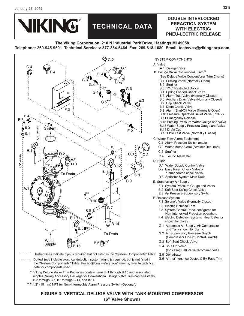
321i
FIgurE 3: VErTICAL DELugE VALVE wITH TANk-mouNTED ComprEssor (6” Valve shown)
TECHNICAL DATA
January 27, 2012
DoubLE INTErLoCkED prEACTIoN sysTEm
wITH ELECTrIC/ pNEu-LECTrIC rELEAsE
The Viking Corporation, 210 N Industrial park Drive, Hastings mI 49058Telephone: 269-945-9501 Technical services: 877-384-5464 Fax: 269-818-1680 Email: [email protected]
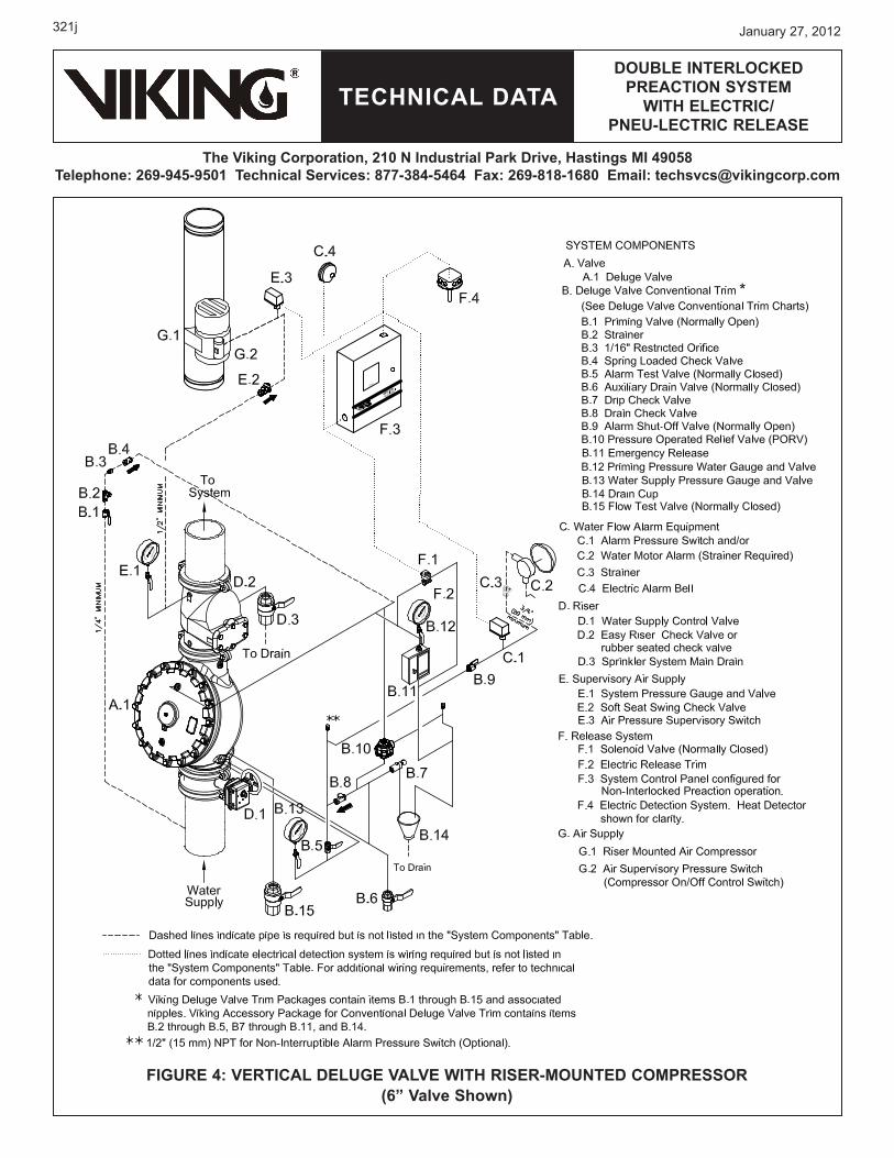
321j
FIgurE 4: VErTICAL DELugE VALVE wITH rIsEr-mouNTED ComprEssor (6” Valve shown)
TECHNICAL DATA
January 27, 2012
DoubLE INTErLoCkED prEACTIoN sysTEm
wITH ELECTrIC/ pNEu-LECTrIC rELEAsE
The Viking Corporation, 210 N Industrial park Drive, Hastings mI 49058Telephone: 269-945-9501 Technical services: 877-384-5464 Fax: 269-818-1680 Email: [email protected]
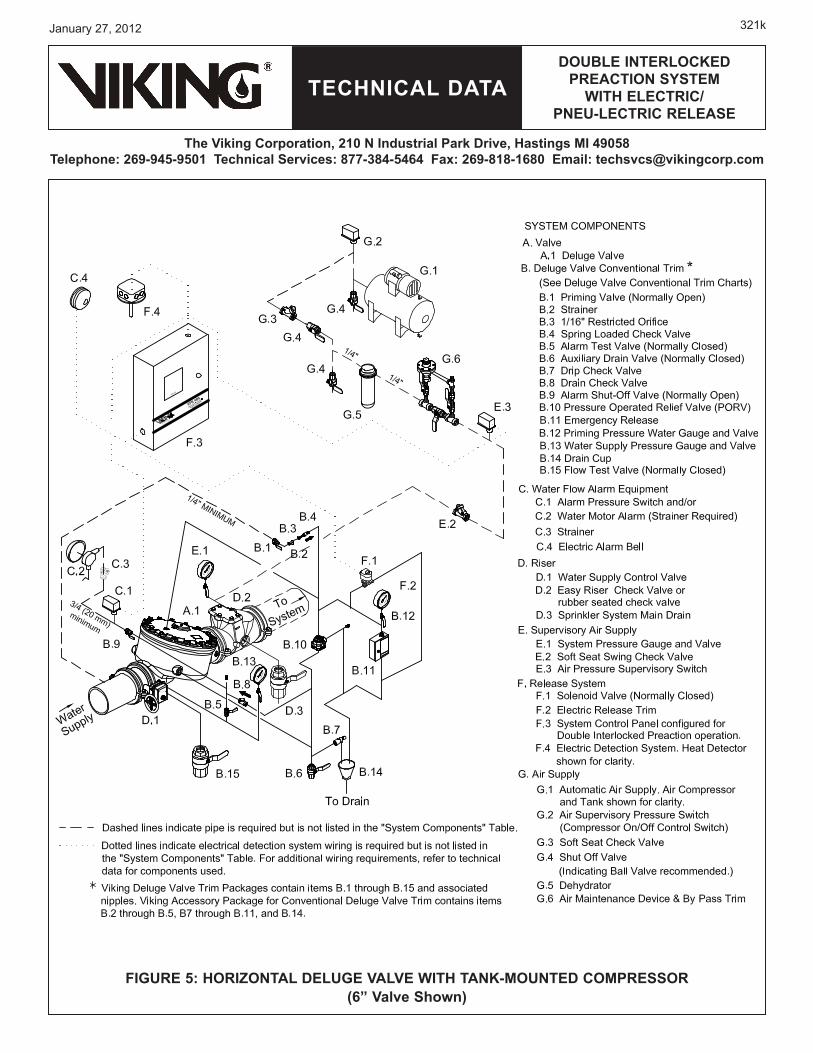
321k
FIgurE 5: HorIZoNTAL DELugE VALVE wITH TANk-mouNTED ComprEssor (6” Valve shown)
TECHNICAL DATA
January 27, 2012
DoubLE INTErLoCkED prEACTIoN sysTEm
wITH ELECTrIC/ pNEu-LECTrIC rELEAsE
The Viking Corporation, 210 N Industrial park Drive, Hastings mI 49058Telephone: 269-945-9501 Technical services: 877-384-5464 Fax: 269-818-1680 Email: [email protected]
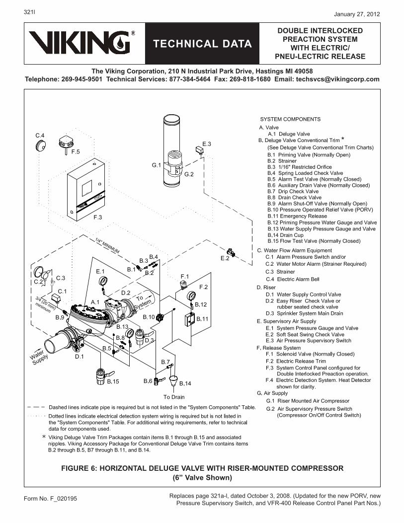
321l
Form No. F_�2�195
FIgurE 6: HorIZoNTAL DELugE VALVE wITH rIsEr-mouNTED ComprEssor (6” Valve shown)
Replaces page 321a-l, dated October 3, 2��8. (Updated for the new PORV, new Pressure Supervisory Switch, and VFR-4�� Release Control Panel Part Nos.)