tardir/mig/a320222 - defense technical information center a power limited or powerless aerospace...
TRANSCRIPT
VOLUME I PERFORMANCE FLIGHT TESTING PHASE
CHAPTER 4 HIGHL/D
19970121 002 JANUARY 1992
USAF TEST PILOT SCHOOL EDWARDS AIR FORCE BASE, CALIFORNIA
DISTRIBUTION STATEMENT A |
Approved for public release; ' Distribution Tbli*:-jfcd i
FORWARD
This set of notes was prepared to supplement the lectures in the
Introductory Soaring Course at the USAF Test Pilot School. We feel that
the new soaring pilot needs a brief look at the long colorful history of
soaring in order to appreciate the design refinements and proven tech-
niques that have made soaring the essence of flight. The TPS student is
well versed in both aerodynamic theory and flight test techniques. For
this reason, a short chapter on the aerodynamics of sailplane performance
was included without a more fundamental development of the theory of
flight. A brief guide to sailplane operations was written to condense
the techniques and procedures of a soaring flight into a convenient
reference source. We hope that this text will kindle in the student a
genuine interest in soaring, and provide him with a sound base for
experiencing this challenging and rewarding endeavor.
PAUL D. TACKABURY Major USAF
USAF TFST PILOT SCHOOL Edwards AFB California November 1979
REVISED BY:
JAMES M. PAYNE Major USAF
March 1986
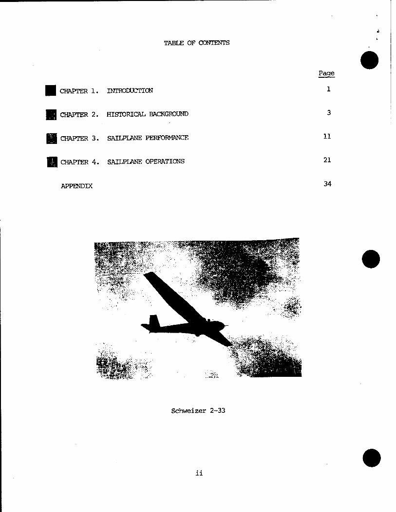
TABLE OF CONTENTS
CHAPTER 1. INTRODUCTION
Page
1
CHAPTER 2. HISTORICAL BACKGROUND
CHAPTER 3. SAILPLANE PERFORMANCE 11
CHAPTER 4. SAILPLANE OPERATIONS 21
APPENDIX 34
Schweizer 2-33
li
CHAPTRR 1
INTRODUCTION
In 1967, the USAF Test Pilot School inaugurated an introductory soaring
program which provided each student with about three hours of sailplane
flying. The program was conceived to expose student test pilots and flight
test engineers to an additional type of aircraft with flying characteristics
unlike any other in the school curriculum. TPS students are regularlv flying
aircraft whose lift-to-drag ratios (L/D) vary respectively from 2.2:1 (T-3R
Low L/D) to 11:1 (A-37). The soaring program completes the hiqher end of
this spectrum with aircraft having an L/D of 36:1 (Grob 103).
The soaring program lends itself effectively to the investigation o^
nonsteady state stability and control flight testing techniques. This type
of testing is presently applied to the T-38 when it is con-Fiqured to simulate
a power limited or powerless aerospace vehicle. Since the motive power of a
sailplane is derived solely from gravity, this nonsteady state test method
is the only way of determining the stability and control characteristics.
The lifting body and space shuttle concepts dictate a gliding, power-off
approach and landing pattern. Consequently, NASA initiated a mandatory soar-
ing program for their lifting body test pilots. Kxperience gained in the TPS
soaring program is likewise expected to benefit and better prepare the school
graduate -for such a test program. It also is a valuable background for opera-
tions where flame-out patterns may be required.
The meteorological state of the atmosphere plays a sionificant role in
soaring flight. The conditions that exist to produce lift are of vital
interest to the soaring pilot. Consequentlv, one of the benefits to be
realized from a soaring program is an increased awareness and appreciation
of the meteorology of flight.
In summary, the objectives of the soaring program are threefold:
a. To introduce TPS pilots to the realm of powerless flight.
b. To allow the TPS pilot to gualitatively evaluate the performance and
stability characteristics of a high L/D aircraft in low subsonic flight under
nonsteady state flight conditions.
c. To better prepare the TPS pilot for present and future test programs.
Chapters 2, 3, and 4 have been written to give the student a familiarity
with sailplanes, their role in aviation, and'their performance and operation.
Technigues for flight testing sailplanes have been purposefully omitted since
the student is expected to have already learned the basic flight testing
technigues. The student is encouraged, however, to extend his "knowledge of
flight testing to include determining the polar and penetration speed for a
sailplane.
CHAPTER 2
HISTORICAL BACKGROUND
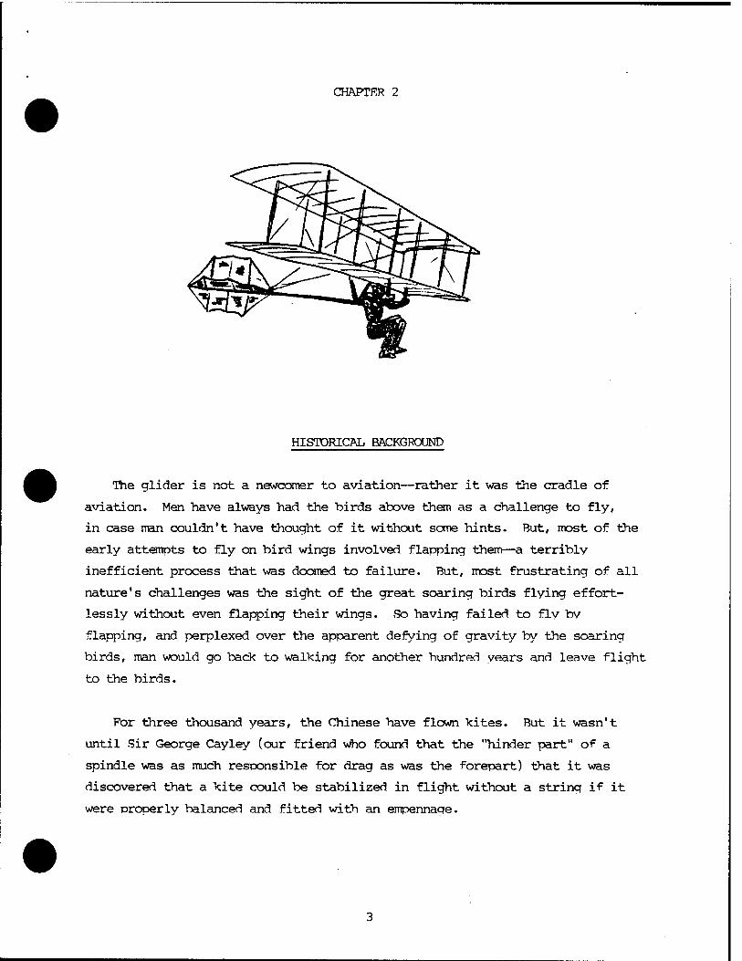
The glider is not a newcomer to aviation—rather it was the cradle of
aviation. Men have always had the birds above them as a challenge to fly,
in case man couldn't have thought of it without some hints. But, most of the
early attempts to fly on bird wings involved flapping them—a terribly
inefficient process that was doomed to failure. But, most frustrating of all
nature's challenges was the sight of the great soaring birds flying effort-
lessly without even flapping their wings. So having failed to flv bv
flapping, and perplexed over the apparent defying of gravity by the soaring
birds, man would go back to walking for another hundred years and leave flight
to the birds.
For three thousand years, the Chinese have flown kites. But it wasn't
until Sir George Cayley (our friend who found that the "hinder part" of a
spindle was as much responsible for drag as was the forepart) that it was
discovered that a kite could be stabilized in flight without a string if it
were properly balanced and fitted with an empennage.
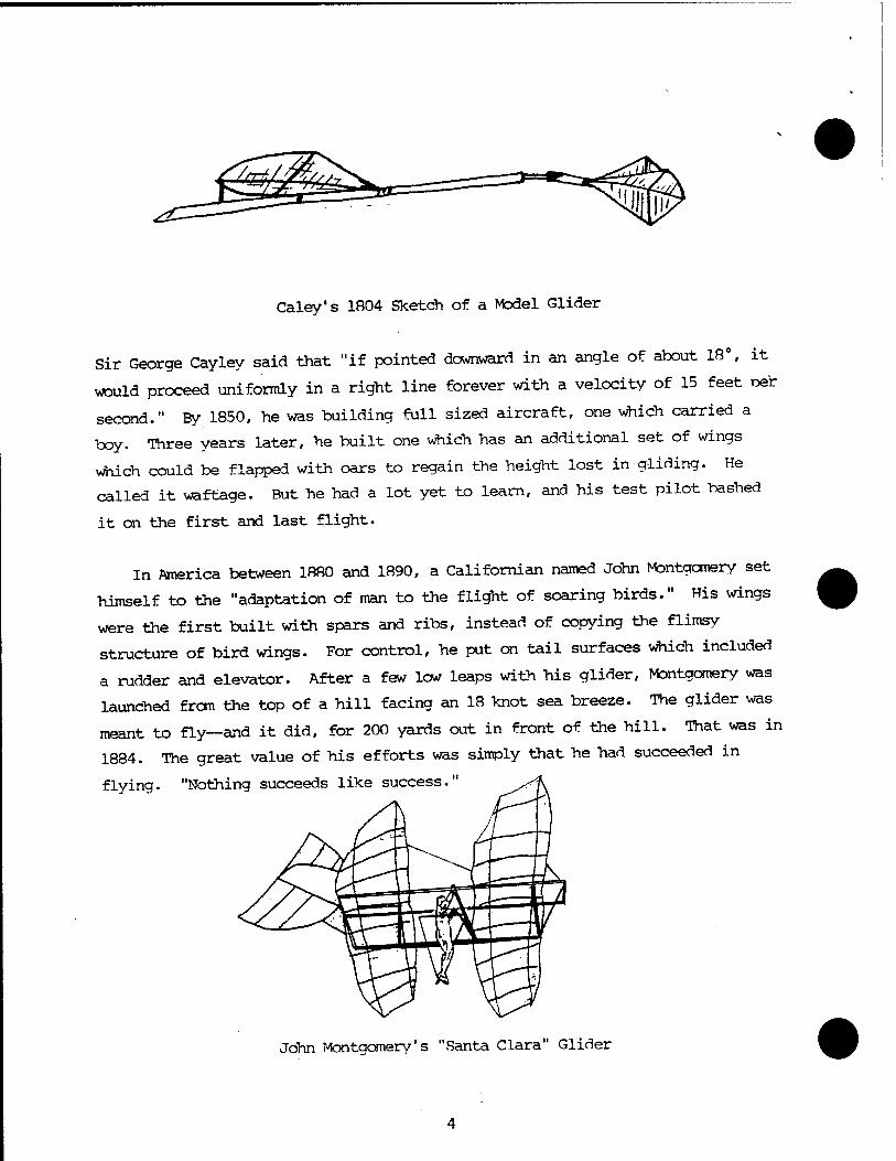
Caley's 1B04 Sketch of a Model Glider
Sir George Cayley said that "if pointed downward in an angle of about 18°, it
would proceed uniformly in a right line forever with a velocity of 15 feet per
second." By 1850, he was building full sized aircraft, one which carried a
boy. Three years later, he built one which has an additional set of wings
which could be flapped with oars to regain the height lost in gliding. He
called it waftage. But he had a lot yet to learn, and his test pilot bashed
it on the first and last flight.
In America between 1880 and 1890, a Californian named John Montgomery set
himself to the "adaptation of man to the flight of soaring birds." His wings
were the first built with spars and ribs, instead of copying the flimsy
structure of bird wings. For control, he put on tail surfaces which included
a rudder and elevator. After a few low leaps with his glider, Montgomery was
launched from the top of a hill facing an 18 knot sea breeze. The glider was
meant to fly—and it did, for 200 yards out in front of the hill. That was in
1884. The great value of his efforts was simply that he had succeeded in
flying. "Nothing succeeds like success."
John Montgomery's "Santa Clara" Glider
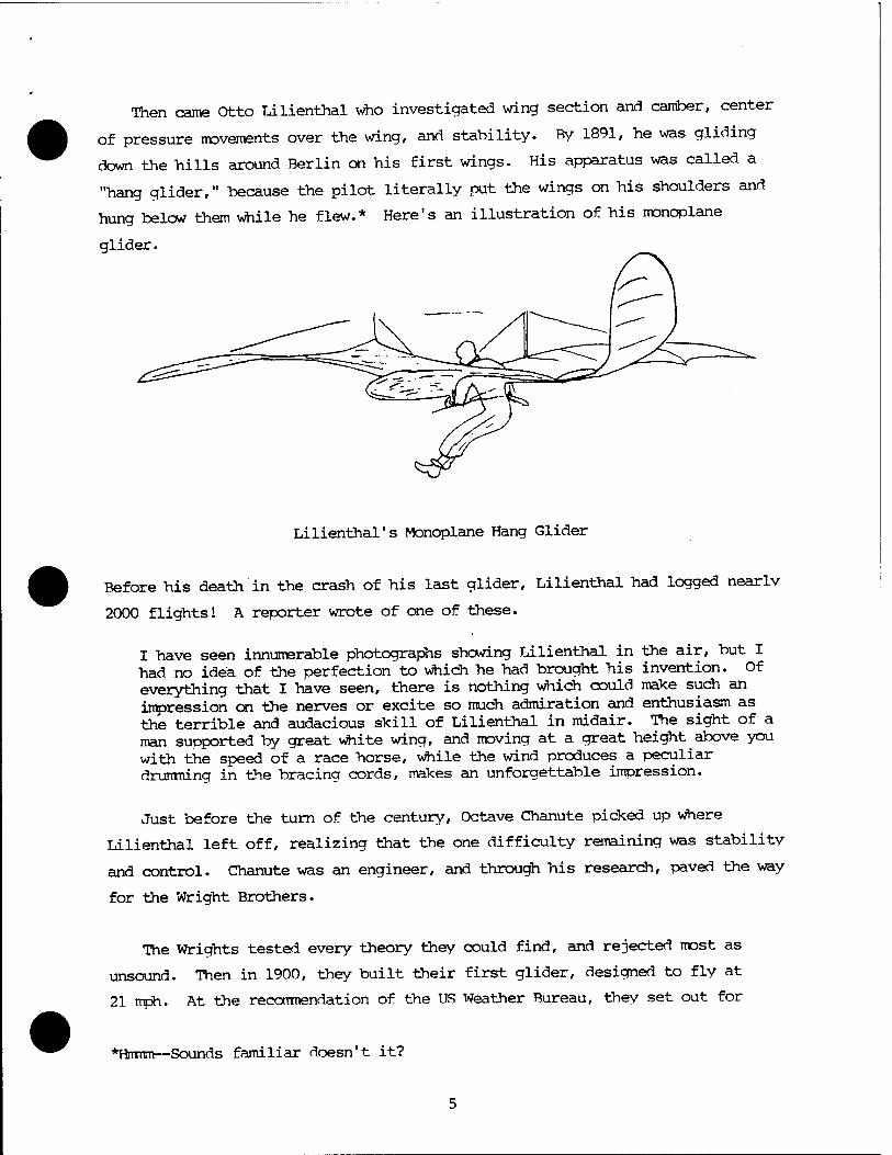
Then came Otto Lilienthal who investigated wing section and camber, center
of pressure movements over the wing, and stability. By 1891, he was gliding
down the hills around Berlin on his first wings. His apparatus was called a
"hang glider," because the pilot literally put the wings on his shoulders and
hung below them while he flew.* Here's an illustration of his monoplane
glider.
Lilienthal's Monoplane Hang Glider
Before his death in the crash of his last glider, Lilienthal had logged nearly
2000 flights! A reporter wrote of one of these.
I have seen innumerable photographs showing Lilienthal in the air, but I had no idea of the perfection to which he had brought his invention. Of everything that I have seen, there is nothing which could make such an impression on the nerves or excite so much admiration and enthusiasm as the terrible and audacious skill of Lilienthal in midair. The sight of a man supported by great white wing, and moving at a great height above you with the speed of a race horse, while the wind produces a peculiar drumming in the bracing cords, makes an unforgettable impression.
Just before the turn of the century, Octave Chanute picked up where
Lilienthal left off, realizing that the one difficulty remaining was stability
and control. Chanute was an engineer, and through his research, paved the way
for the Wright Brothers.
The Wrights tested every theory they could find, and rejected most as
unsound. Then in 1900, they built their first glider, designed to fly at
21 mph. At the recommendation of the US Weather Bureau, they set out for
*Hrrmm—Sounds familiar doesn't it?
Kitty Hawk, NC to find the wind conditions they "had designed for. The glider
worked, but only in near gale strength winds for lack of sufficient wing area.
The following vear, the Wrights returned with a new glider with nearly twice
the wing area. It flew slightly better—but disappointed them greatly. With
the encouragement of Octave Chanute, they built a third glider with an aspect
ratio of 6:1 (AR for the Grob 103 is 17:1!) and flew it in the summer of 1<X)2.
With this highly successful glider, they flew over a thousand flights—some
in winds over 36 mph! One observer said, "All she needs is a coat of feathers
to maker her light, and she'll stay in the air indefinitely."
By 1903, the Wrights felt they had learned enough to add an engine, and
the airolane was born. The glider all but dropped from history.
Gliding as a sport was born in Germanv about 1909 with school bovs flyinq
copies of Lilienthal's hang gliders in the Rhön Mountains on the slopes of the
Wasserkuppe. Flights of 1000 yards were made in the next few years, just
before the First World War. The war ended these gliding experiments, and it
was not until 1920 that a group of enthusiasts met again at the Wasserkukppe
to build a second generation of hang gliders and compete for distance. Ry
1920, it was inevitable that the glider would have to look more like the air-
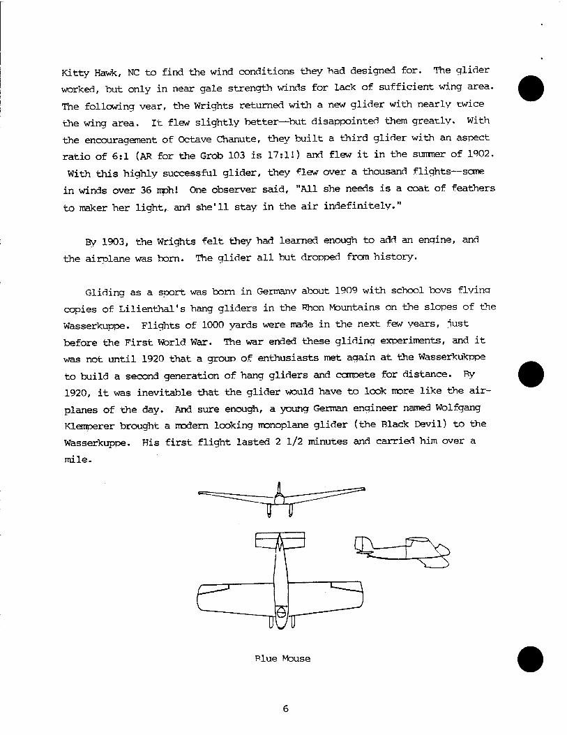
planes of the day. And sure enough, a young German engineer named Wolfgang
Klemperer brought a modern looking monoplane glider (the Black Devil) to the
Wasserkuppe. His first flight lasted 2 1/2 minutes and carried him over a
mile.
Plue Mouse
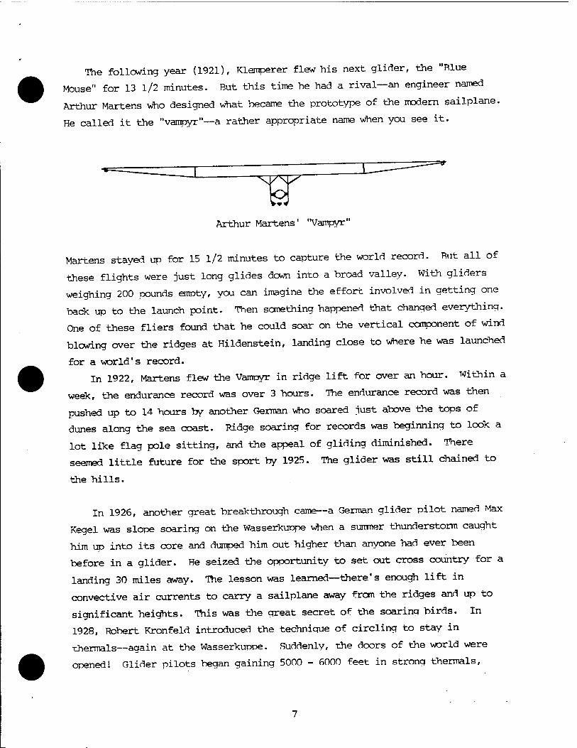
The following year (1921), Klemperer flew his next glider, the "Blue
Mouse" for 13 1/2 minutes. But this time he had a rival—an engineer named
Arthur Martens who designed what became the prototype of the modern sailplane.
He called it the "vampyr"—a rather appropriate name when you see it.
Arthur Martens' 'Vampyr"
Martens stayed up for 15 1/2 minutes to capture the world record. But all of
these flights were just long glides down into a broad valley. With gliders
weighing 200 pounds empty, you can imagine the effort involved in getting one
back up to the launch point. Then something happened that changed everything.
One of these fliers found that he could soar on the vertical component of wind
blowing over the ridges at Hildenstein, landing close to where he was launched
for a world's record.
In 1922, Martens flew the Vampyr in ridge lift for over an hour. Within a
week, the endurance record was over 3 hours. The endurance record was then
pushed up to 14 hours by another German who soared just above the tops of
dunes along the sea coast. Ridge soaring for records was beginning to look a
lot like flag pole sitting, and the appeal of gliding diminished. There
seemed little future for the sport by 1925. The glider was still chained to
the hills.
In 1926, another great breakthrough came—a German glider pilot named Max
Kegel was slope soaring on the Wasserkuppe when a summer thunderstorm caught
him up into its core and dumped him out higher than anyone had ever been
before in a glider. He seized the opportunity to set out cross country for a
landing 30 miles away. The lesson was learned—there's enough lift in
convective air currents to carry a sailplane away from the ridges and up to
significant heights. This was the great secret of the soaring birds. In
1928, Robert Kronfeld introduced the technique of circling to stay in
thermals—again at the Wasserkuppe. Suddenly, the doors of the world were
opened 1 Glider pilots began gaining 5000 - 6000 feet in strong thermals,
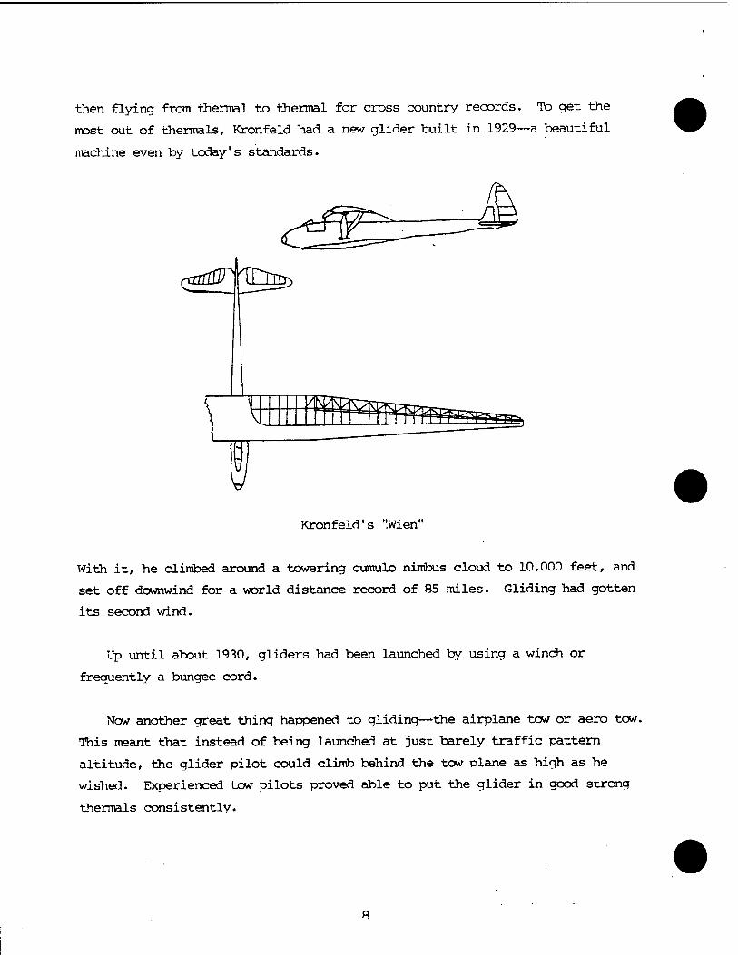
then flying fron thermal to thermal for cross country records. To get the
most out of thermals, Kronfeld had a new glider built in 1929—a beautiful
machine even by today's standards.
Kronfeld's ".Wien"
With it, he climbed around a towering cumulo nimbus cloud to 10,000 feet, and
set off downwind for a world distance record of 85 miles. Gliding had gotten
its second wind.
Up until about 1930, gliders had been launched by using a winch or
frequently a bungee cord.
Now another great thing happened to gliding—the airplane tow or aero tow.
This meant that instead of being launched at just barely traffic pattern
altitude, the glider pilot could climb behind the tow plane as high as he
wished. Experienced tow pilots proved able to put the glider in good strong
thermals consistently.
By 1931, competition swung from duration to distance. Prizes were no
longer awarded for duration flights. Distance flying was the thing. Thermals
lasted only during the hours of sunshine and then diminished at night. So,
there was a practical limit to the time available for covering ground. Glider
design shifted from very low cruise speeds to much higher design speeds per-
mitting more miles to be covered while the thermals lasted. By 1935, the
distance record stood at 314 miles. The pendulum had swung far the other way.
In competition flying, the gliders could not be retrieved from such great
distance before the start of the next day's activities, and this created
problems which were partly solved by reguiring roundrobin flights.
Ridge and thermal soaring had been well worked out by the mid 1930s. And
then, the big league was discovered, the mountain wave. A large mountain
range was found to disturb the winds in the atmosphere for more than 50,000
feet above it. The mountain acted like a rock in the bed of a fast, shallow
stream. It forced the flow above it into a wave which continued for some
distance downstream. Often these great waves in the air are marked by
characteristic lenticular cloud like the famous Tehachapi Wave.
Altitude records soared upward. In 1939, a Luftwaffe captain flew to an
unprecedented 21,400 feet. It was time to start thinking about oxygen svstems
and ultimately pressurization.
Gliding caught on in England—then in America, and continued strong in
Europe until World War II brought an abrupt end to the golden years of sport
gliding. Gliders were used by all nations in wartime operations, primarily as
troop transports. Then after five years of war, the idea of soaring again was
irresistible to the prewar glider pilots. But, there were few gliders around
to fly. To remedy this, a furniture company in England built a hundred
Olympia gliders. The Slingsby Sailplane Company went into operation in
England, along with Schweizer in the US. Gradually, sport gliding became a
vital part of the aviation picture around the world.
By 1950, the world altitude record stood at 42,000 feet. In 1961, Paul
Bikle took a Schweizer 1-23E to 46,267 feet in the vicinity of Koehn Drv Lake,
California! He used oxygen, but had no pressurization, as he rode the qreat
Tehachapi Wave to a world altitude record for sailplanes. In April 1<W3 a
California glider pilot flew a Kestrel W fron Mojave, California to Seminole,
Texas to tie the world distance record of 907 statue miles.
The state of the art has progressed to the point that the hest Open Class
sailplane has a 24.5 meter wing span and a measured best L/D of 60:1.
■ Competition has alwavs been a strong part of the motivation for soarina.
Rut concurrent with the amassing of impressive world records, glider
enthusiasts have built a fine sport which has gained great popularity in
recent years. Part of the credit for this broadened popular interest is due
to professional soaring organizations, such as the .Soarina Societv of America.
Through their efforts, soaring has been expanded to include not only the
purists, but the average citizen as well. Commercial soaring schools are
springing up around the world. The sport has come of age.
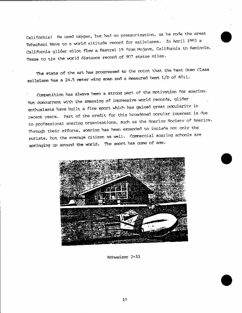
Schweizer 2-33
10
CHAPTER 3
SAILPLANE PERFORMANCE
11
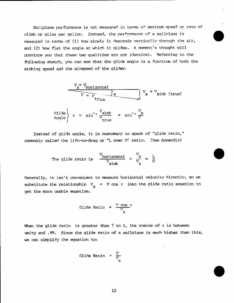
Sailplane performance is not measured in terms of maximum speed or rate of
climb or miles per gallon. Instead, the performance of a sailplane is
measured in terms of (1) how slowly it descends vertically through the air,
and (2) how flat the angle at which it glides. A moment's thought will
convince you that these two gualities are not identical. Referring to the
following sketch, you can see that the glide angle is a function of both the
sinking speed and the airspeed of the glider.
x horizontal
V = V true
Glide I Angle I
y = sin . -i sink
s sink (true)
V, = sin true
V 1 s V
Instead of glide angle, it is customary to speak of "glide ratio,"
commonly called the lift-to-drag or "L over D" ratio. (See Appendix)
V, The glide ratio is
horizontal V sink
JE - k V D s
Generally, it isn't convenient to measure horizontal velocity directly, so we
substitute the relationship
get the more usable equation.
substitute the relationship V = V cos y into the glide ratio equation to
Glide Ratio = v cos Y v
When the glide ratio is greater than 7 to 1, the cosine of Y is between
unity and .99. Since the glide ratio of a sailplane is much higher than this,
we can simplify the equation to:
Glide Ratio V
12
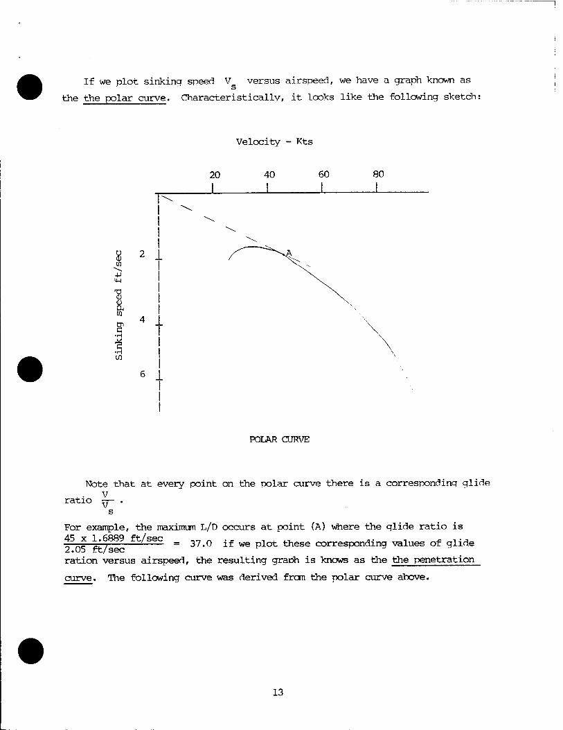
If we plot sinking speed V versus airspeed, we have a graph known as
the the polar curve. Characteristically, it looks like the following sketch:
Velocity - Kts
20 40 60 80
u
T3 CD
a
■s ■H CO
\
POLAR CURVE
ratio
Note that at every point on the polar curve there is a corresponding glide V V
For example, the maximum L/D occurs at point (A) where the glide ratio is
o5n? k*/889 ft'seC = 37.0 if we plot these corresponding values of glide Z, • yJO ITC/ S6C
ration versus airspeed, the resulting graph is knows as the the penetration
curve. The following curve was derived from the polar curve above.
13
o
-H H o
38
36
34
32
30
28
26
24
20
Velocity - Kts
40 60 80
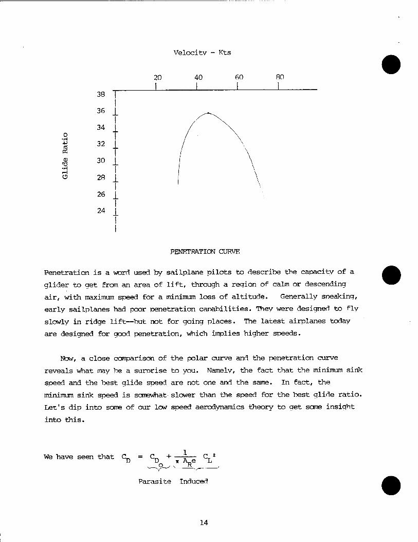
PENETRATION CURVE
Penetration is a word used by sailplane pilots to describe the capacity of a
glider to get from an area of lift, through a region of calm or descending
air, with maximum speed for a minimum loss of altitude. Generally speaking,
early sailplanes had poor penetration capabilities. They were designed to fly
slowly in ridge lift—but not for going places. The latest airplanes today
are designed for good penetration, which implies higher speeds.
Now, a close comparison of the polar curve and the penetration curve
reveals what may be a surprise to you. Namely, the fact that the minimum sink
speed and the best glide speed are not one and the same. In fact, the
minimum sink speed is somewhat slower than the speed for the best glide ratio.
Let's dip into some of our low speed aerodynamics theory to get some insight
into this.
We have seen that CL. = CL, + a2
Parasite Induced
14
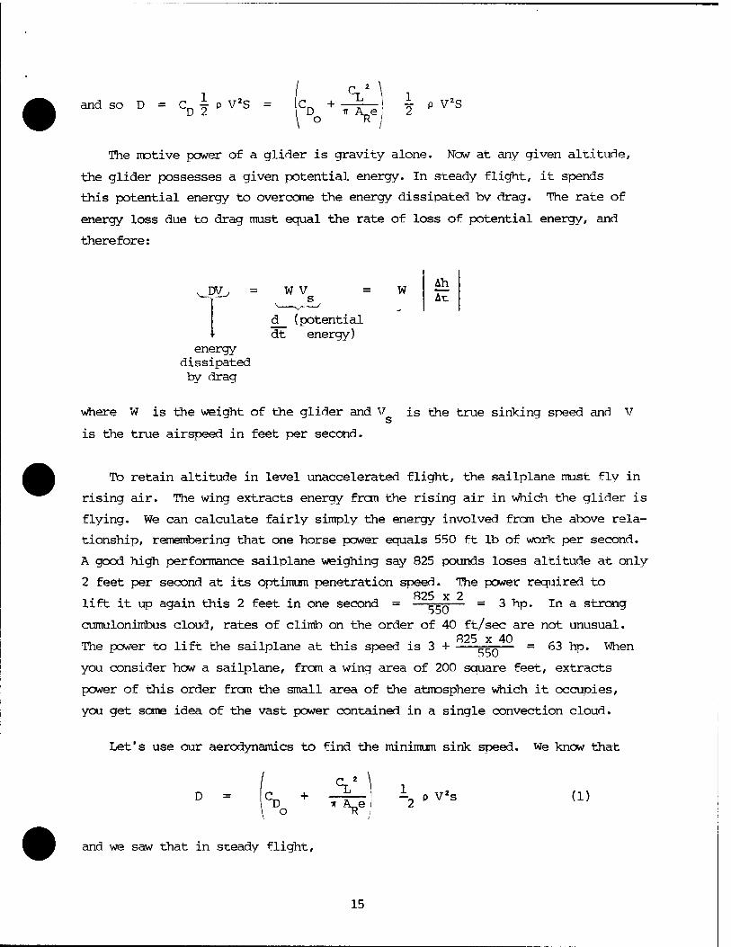
and so D = C ^ p V2S = C + -%_l I p V2S D IT A e, 2
\ O -R /
The motive power of a glider is gravity alone. Now at any given altitude,
the glider possesses a given potential energy. In steady flight, it spends
this potential energy to overcome the energy dissipated bv drag. The rate of
energy loss due to drag must equal the rate of loss of potential energy, and
therefore:
vj: *L> = W V s
' d (potential dt energy)
energy
by c Irag
w Ah At
where W is the weight of the glider and V is the true sinking speed and v
is the true airspeed in feet per second.
To retain altitude in level unaccelerated flight, the sailplane must fly in
rising air. The wing extracts energy from the rising air in which the glider is
flying. We can calculate fairly simply the energy involved from the above rela-
tionship, remembering that one horse power equals 550 ft lb of work per second.
A good high performance sailplane weighing say 825 pounds loses altitude at only
2 feet per second at its optimum penetration speed. The power required to 825 x 2
lift it up again this 2 feet in one second = —s^— = 3 hp. In a strong
cumulonimbus cloud, rates of climb on the order of 40 ft/sec are not unusual. 825 x 40
The power to lift the sailplane at this speed is 3 H FFTä— = 63 hp. When
you consider how a sailplane, from a wing area of 200 square feet, extracts
power of this order from the small area of the atmosphere which it occupies,
you get some idea of the vast power contained in a single convection cloud.
Let's use our aerodynamics to find the minimum sink speed. We know that
D = |C^ + _ f „ ! -2 P V2s (1)
and we saw that in steady flight,
15
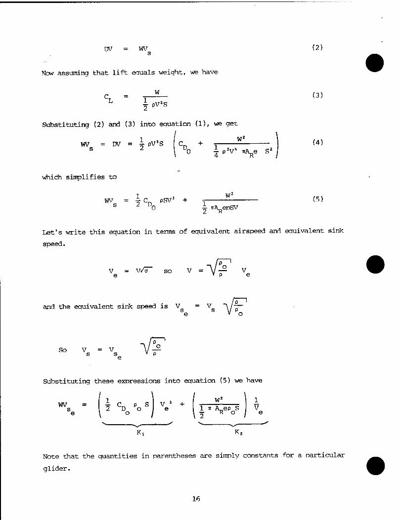
DV WV (2) s
Now assuming that lift ecfuals weight, we have
C = 5L_ (3) L \ PV«S
Substituting (2) and (3) into equation (1), we get
1 „3„ „ W WV = DV = 4 PV3S C_ + ■= (4) s 2 1 Do i- pV ir^e S2 '
which simplifies to
WV = ic PSV3 + -, (5) S Z ' 0 ± irÄ^epSV
Let's write this equation in terms of equivalent airspeed and eouivalent sink
speed.
V = V/o so V = V— v e » p e =VF and the equivalent sink speed is V = Vg ~\/~
e V o
So V = V s s e
VF Substituting these expressions into equation (5) we have
WV = I J- CL p S I V 3 + ' W s 2 D o e I 1 IT A_ep S V e \ o / \ ■=■ R o / e
K, K2
Note that the quantities in parentheses are simply constants for a particular
glider.
16
K! Kj
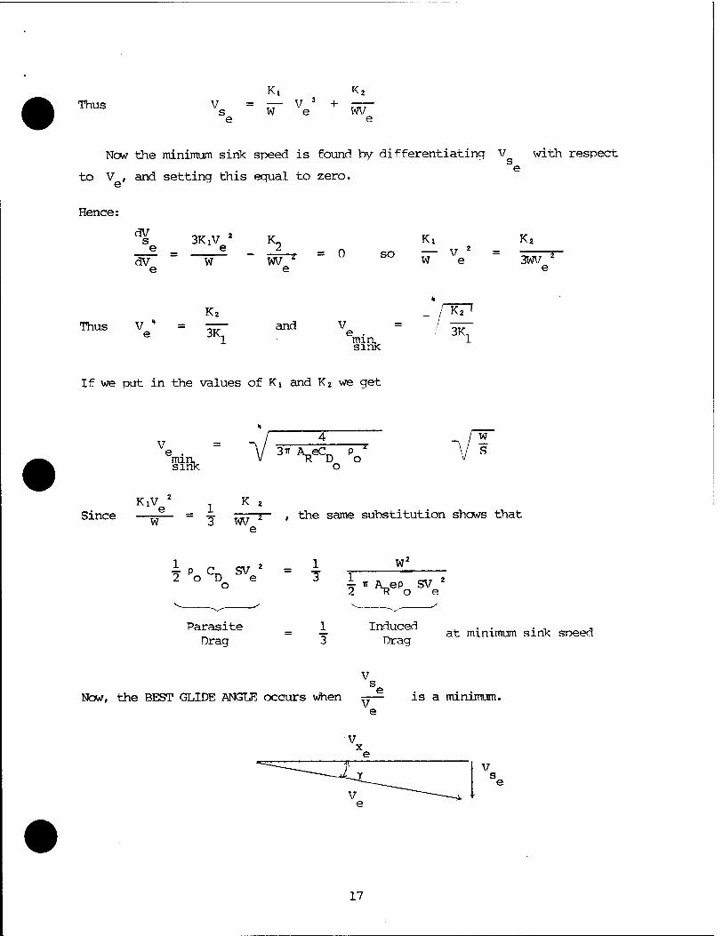
Thus Vs = vT Ve + wF e e
New the minimum sink speed is found by differentiating V with respect s e
to V , and setting this equal to zero.
Hence:
dV s 6
dV
3KiV 2 K,
W 2
wv " Ki
= 0 so — V s
W e
K,
3WV 2
e
Kj
Thus V " e 3K,
and V "TP
min, sink
3K,
If we put in the values of Ki and K2 we get
V min, sink ^VS V
/ w
KlVe 1 K 2
Since —r^— = -*■ w i , the same substitution shows that
i P a. sv 2 2 o D e
o
1 3
W -*• TT A_ep SV 2 K o e
Parasite Drag
Induced Drag
at minimum sink speed
V
Now, the BEST GLIDE ANGLE occurs when V is a minimum.
V
17
We saw that V s e
K,v 3 1 e VI
+ K2
WV e
V
e
K.V 2 1 e W
K2
WV 2
e
Differentiating this with respect to V and equating to zero, we find that
K2 4 w* V * = — = —
o
or
Ve . V ^ A^ep «C_ V S min V T? Ko D V glide angle
Since at the best glide angle, K, V = K2
1 VQ V 3 V
we have -J C^ p SV 2 - W
2 D Ho e 1 . _r ,
or: Parasite Drag = Induced Drag
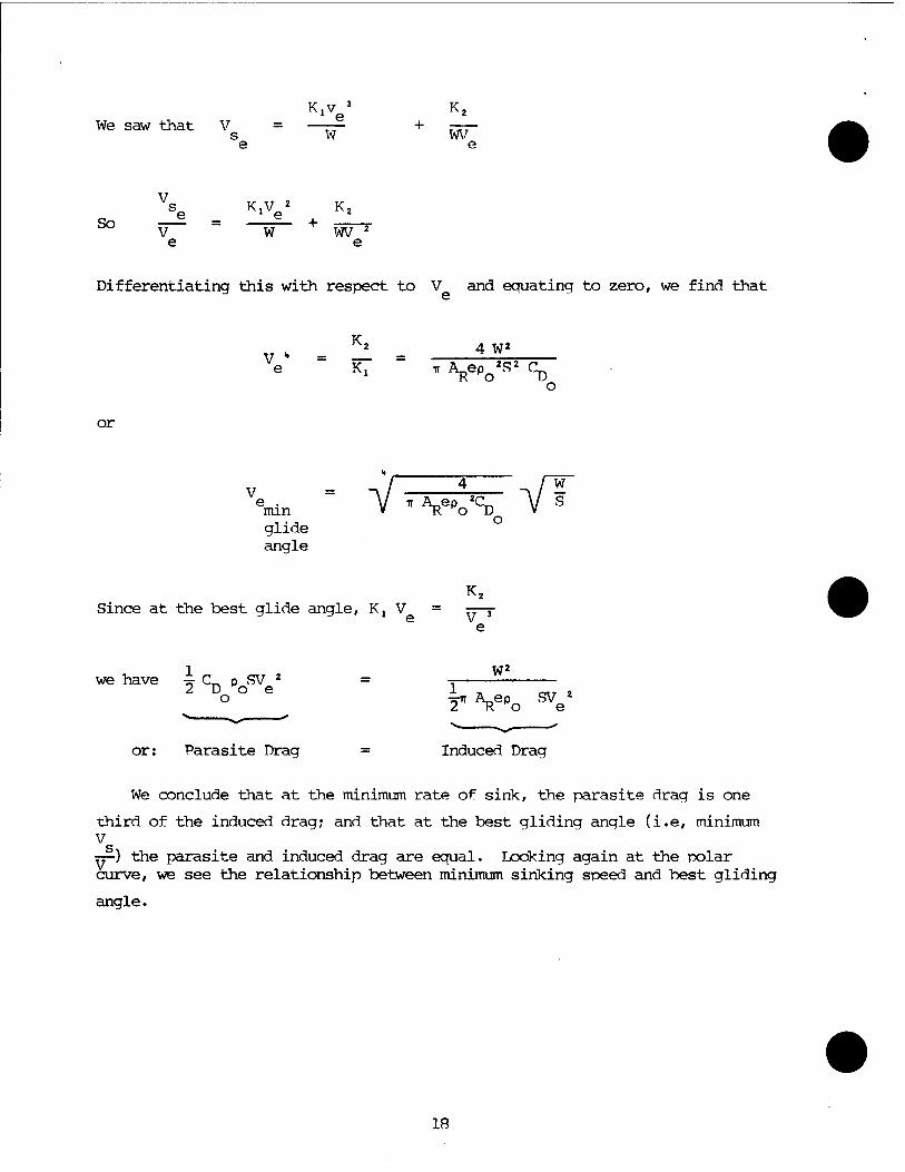
We conclude that at the minimum rate of sink, the parasite drag is one
third of the induced drag; and that at the best gliding angle (i.e, minimum V ry-) the parasite and induced drag are equal. Looking again at the polar curve, we see the relationship between minimum sinking speed and best gliding
angle.
18
mm .'**«
SfSftM
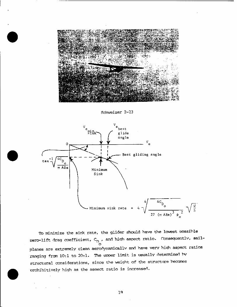
Schweizer 2-23
3 2 27 (TT ARe) p o
To minimize the sink rate, the glider should have the lowest possible
zero-lift drag coefficient, Cn , and hiqh aspect ratio. Consequently, sail- o
planes are extremely clean aerodynamicallv and have very high aspect ratios
ranging from 10:1 to 20:1. The upper limit is usually determined bv
structural considerations, since the weight of the structure becomes
prohibitively high as the aspect ratio is increased.
19
Higher penetration speeds "have resulted from the use of low drag laminar
airfoils. These, as you recall, are usually very smooth and have their
maximum thickness near the mid chord. Rain, ice, and dirt can radically alter
the flying characteristics of an airfoil, particularly one which achieves its
performance by promoting laminar flow.
From all of this, we conclude that we should fly in lift at the minimum
sink speed if gaining altitude is our primary aim. On the other hand, if we
are covering distance, as on a cross country flight, we would want to fly at
the MacCready "speed to fly" which gives us the best speed. Higher speeds are
also useful to carry us through regions of sink.
It should be apparent that one of the most important results of glider
flight testing is the polar curve showing sink rate versus airspeed. From
this curve, the minimum sink speed and the best glide speed can be determined
graphically. The curve is obtained experimentally by measuring sink rates
corresponding to different airspeeds. Since vertical speed is not a good
flight test instrument, it is customary to time a descent through 500 foot
altitude bands, and to average the results. It is important to consider pitot
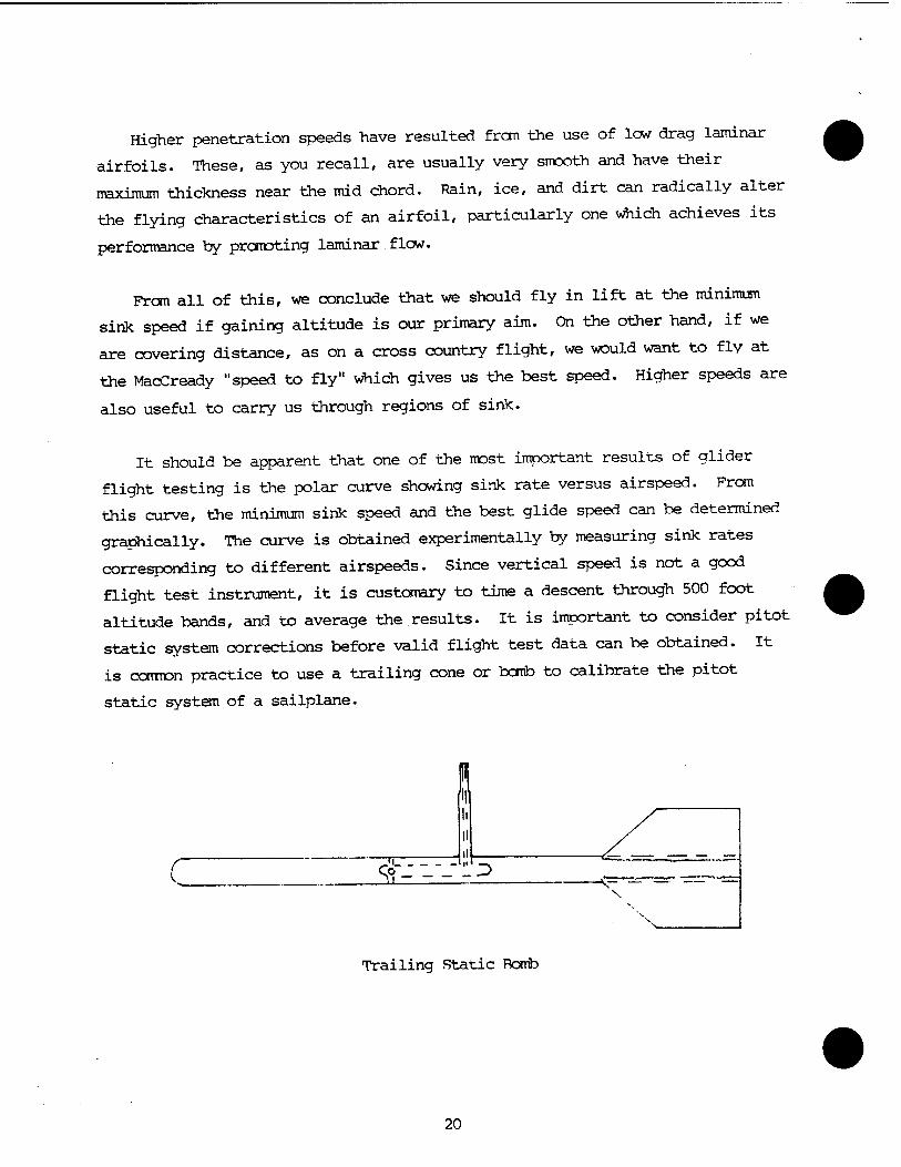
static system corrections before valid flight test data can be obtained. It
is common practice to use a trailing cone or bomb to calibrate the pitot
static system of a sailplane.
r
i
^ MI -S-D
-\- \
Trailing Static Romb
20
CHAPTER 4
SAILPLANE OPERATIONS
This chapter is a collection of procedures and techniques used by-
most sailplane operations. Liberal reference was made to practices
recommended by the Soaring Society of America in their publication,
American Soaring Handbook, Volumes 2 and 4. In a few instances, these
procedures have been altered to coincide with recommended procedures
at the soaring site used by the School.
21
PREFLIGHT INSPECTION
The glider should be preflighted IAW the appropriate checklist.
Sailplanes are designed to be dismantled and trailered. Therefore, special
care should be taken to ensure that the structure is rigged properly and that
the flight controls are connected.
TAKEOFF
When the sailplane pilot has completed the before takeoff checks and is
ready, the crewman will attach the towline to the sailplane. On the first
flight of the day, the pilot should pull the tow release to check operation
and signal for rehook.
When the sailplane pilot is ready for takeoff, he gives the wing runner a
thumbs up. The runner levels the wings. At this signal, the tow pilot will
move the tow plane forward until the rope tightens. The crewman will assist
the sailplane pilot in checking air and ground traffic, wind conditions, anri
runway ahead before takeoff. The sailplane pilot is the pilot-in-command, and
only he signals for takeoff. This signal is given by fanning the rudder
several times. The tow plane pilot will in turn fan his rudder to signal he
acknowledges the glider is ready. CAUTION: DO NOT MOVE RUDDER PEDALS AFTER
THE WING IS RAISED UNTIL READY FOR TAKEOFF i
The tow pilot will then smoothly apply full power and start his normal
takeoff. The sailplane pilot should relieve the weight on the nose or tail
skid/wheel as soon as possible with the appropriate elevator input without
slamming the nose or tail to the ground. The crewman will run with the wing
tip, keeping the wings level until aileron control is obtained by the
sailplane pilot.
During the ground roll, the sailplane pilot maintains wings level with
ailerons and lateral position behind the tow plane with rudder. The sailplane
22
should be allowed to fly itself off. As in formation flying, the pilot should
position the sailplane by reference to established position points on the tow
plane. Avoid getting too high on takeoff. If the sailplane pilot gets too
high, the tow pilot may be forced to release his end of the tow rope and let
the sailplane pilot fend for himself.
Often, the sailplane pilot's visibility is restricted by dust and dirt on
the initial takeoff. Allow the sailplane to fly off normally. Sufficient
visual cues will still be available for making a normal takeoff.
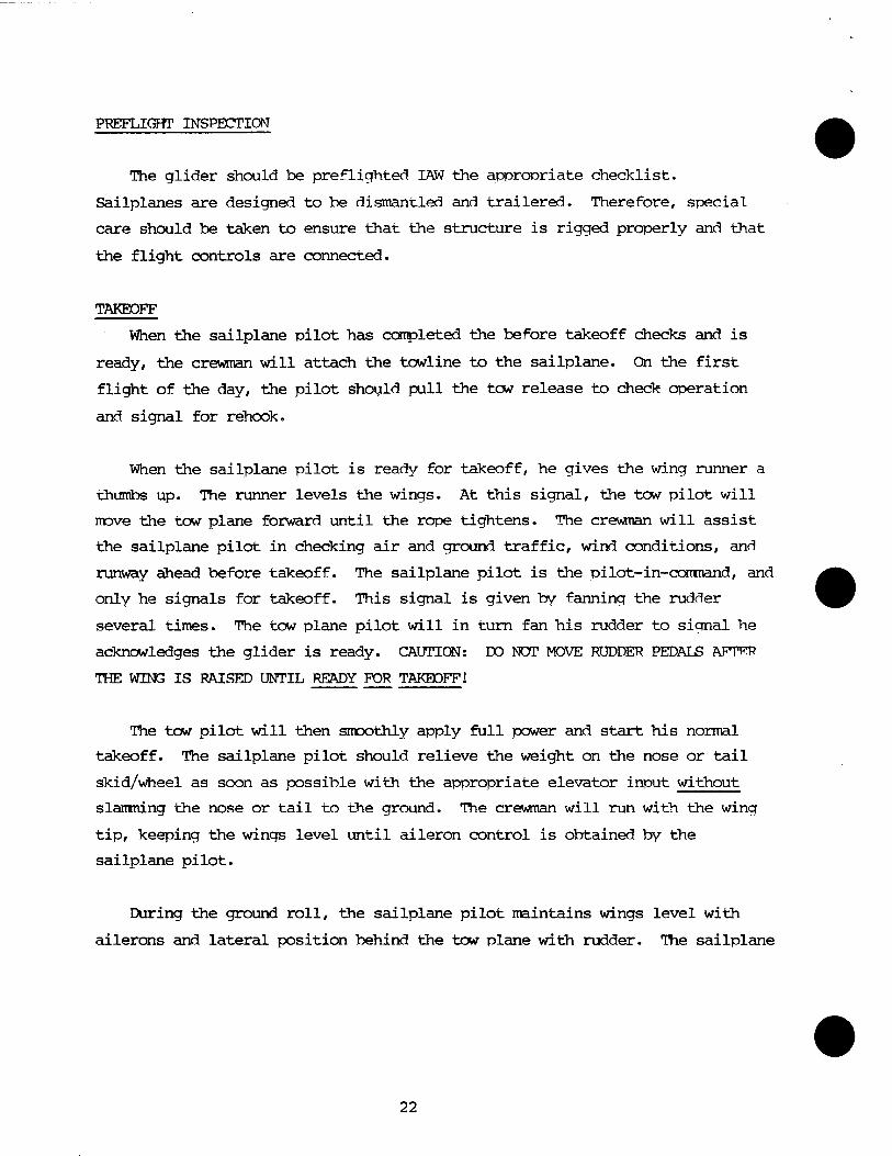
In crosswind conditions, the sailplane, which becomes airborne before the
tow aircraft, should be crabbed over the runway in order to maintain a track
behind the path of the tow plane. Again, as on a normal takeoff, the sail-
plane should be properly positioned by aligning the reference points on the
tow plane. Once the tow plane is airborne, the tow pilot will establish the
drift correction and the sailplane pilot should simply maintain his
established position directly behind the tow plane, keeping the towline
straight by means of the reference points.
■it-' rm
--■■-«u*—>«a-«--i . ----- ■■ - &>-"»(-«!~;': Sii3?JÄ*«i»S;"-»-j&'KJSMT-:*»--«'
..... «aw.td^ii r 4
Schweizer 1-26 with Wing Raised to Indicate that the Pilot is Ready for Takeoff
23
•■•■-•■ ■■■■■? w&&&*aki%m
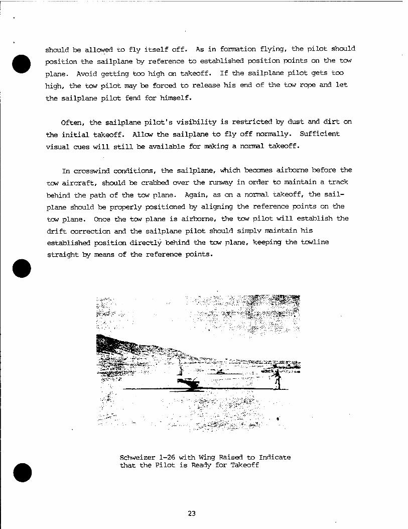
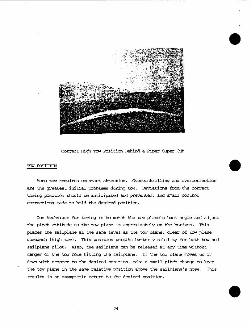
Correct High Tow Position Behind a Piper Super Cub
TOW POSITION
Aero tow requires constant attention. .Overcontrolling and overcorrection
are the greatest initial problems during tow. Deviations from the correct
towing position should be anticipated and prevented, and small control
corrections made to hold the desired position.
One technique for towing is to match the tow plane's bank angle and adjust
the pitch attitude so the tow plane is approximately on the horizon. This
places the sailplane at the same level as the tow plane, clear of tow plane
downwash (high tow). This position permits better visibility for both tow and
sailplane pilot. Also, the sailplane can be released at any time without
danger of the tow rope hitting the sailplane. If the tow plane moves up or
down with respect to the desired position, make a small pitch change to keep
the tow plane in the same relative position above the sailplane's nose. This
results in an asymptotic return to the desired position.
24
To maintain the correct position in a turn, the sailplane pilot should
continue to hold position by using the reference points. All else being
equal, a good technique is to delay turning until the point where the towplane
started its turn. The nose of the glider will be pointed at the tow ship's
outside wingtip, a relationship that will last through the turn. Note that
the sailplane and tow plane ideally fly around the arc of a circle. The
center of turn and radius are the same for both aircraft. Due to the
different speeds of the wingtips when turning, the sailplane always seeks
to roll into the turn (i.e., steepen its bank angle). Apply required control
inputs to both stick and rudder to compensate for this over banking tendency.
When in the correct position, your radius and airspeed are the same as the tow
plane's. Therefore, your bank angle must match his to stay in position.
To signal the tow pilot to turn or alter his heading, the sailplane pilot
should obtain the maximum possible displacement to the side away from the
direction he wishes the tow to turn. This tends to force the nose of the tow
plane in the desired direction. This procedure should be used an absolute
minimum due to the danger of unwanted acceleration. If the tow plane turns
into you during this signal, you will have a huge slack line with which to
contend.
If the rope breaks below 200' AGL, land straight ahead, turning only to
avoid obstacles. Above 200'AGL, a turn back to a downwind landing can be
accomplished safely. Maintain a minimum of best L/D glide speed and turn in
the shortest direction. If you are crabbing into a crosswind, the shortest
direction will be into the crosswind. Above 500' AGL, you will normally have
enough altitude to make a short, modified pattern to land into the wind. A
good technique is to practice calling out loud "200 feet" and "500 feet."
This reminds you of the zone you are in so that you can react quickly and
correctly to a rope break.
25
DESCENTS
Descents on Tow;
Descents on tow should be made only when absolutely necessary such as
lowering ceiling or inability to disconnect. If necessary, the sailplane
pilot must recognize the hazard of over running which results when the tow
descends with a vertical speed greater than the sinking speed of the
sailplane. The sailplane pilot should apply slips or spoilers to produce
sufficient drag and sink rate to prevent over running.
DIFFICULTIES ENCOJNTERED ON TCW
1. Waiting too long to correct what appears to be only small deviations.
Make smooth and timely corrections when deviations from proper tow position
are noted. At all times, the sailplane should be kept aligned with the
reference points on the tow plane. The importance of matching the tow plane's
bank angle to remain in the correct lateral position behind the sailplane
cannot be over emphasized.
2. Too High on Tow. This is the hardest error to correct since the
sailplane will tend to overrun the towline when nosed over to return to the
correct position. Slack in the towline, if improperly taken out, causes a
jerk which either breaks the rope or slingshots the aircraft back to a too
high position. To descend from a too high position without obtaining
excessive towline slack, the sailplane should be slipped or yawed to one side
with rudder. If in a turn, yawing is accomplished by applying outside rudder
and steepening the bank slightly. As the rope tightens, make sure your
airspeed is adjusted to match the tow plane speed. Trim the sailplane. Not
all sailplanes have enough trim power to make stick force zero. The closer
you are to the proper trim, the easier it is to maintain proper position.
3. Over Correcting in Recovery to Normal Tow Position. This familiar
over controlling error may be avoided by releasing the corrective control
pressure when the sailplane starts to respond so that a counter pressure may
be applied prior to reaching the correct position. Again, the sailplane pilot
26
should be entirely dependent upon the tow plane reference points. His line of
sight is to the vertical stabilizer and centerline of the tew aircraft. A
common error is establishing too great a bank angle to return to proper tow
position and then failing to "lead" with the proper controls prior to reaching
the proper tow position. USE SMALL RANK ANGLES, MINIMIZE USE OF AILERONS, AND
ALWAYS "LEAD" WITH THE DESIRED LATERAL INPUT DUE TO THE SLOW ROLLING RESPONSE
OF MOST GLIDERS.
4. Encountering Tow Plane Wake. The wake is a region of turbulence about
a wingspan across running behind the tow aircraft. The tip vortices of
heavier tow planes are easily identified. This amounts to a region of
unpleasant flying, and should normally be avoided. Usually, the easiest
correction is to pull up out of the region of disturbed airflow. All
sailplanes have the control power to safely fly in the wash.
5. Turbulence. Turbulence has a naturally greater effect on the
sailplane than the tow ship because of the sailplane's low wing loading.
Maintaining proper tow position in turbulent conditions is best accomplished
by keeping the tow plane the proper distance above the top of the instrument
panel, thus making asymptotic corrections.
RELEASE FROM TOW
The sailplane pilot should release from the tow plane on a normal taut
line. No attempt should be made to relieve some of the towline tension before
release. The release knob is pulled and held until the sailplane is free of
the towline.
Following the release, the sailplane pilot should make an immediate, but
very moderate, right climbing turn to clear the towline and to gain a little
more altitude transitioning from tow to gliding speed. The tow plane will
turn left and descend.
If the tow plane rocks his wings during the tow portion of the flight, the
sailplane must release. This means that the tow pilot has encountered a
problem such as engine failure.
27
Normally, the sailplane releases at a predetermined point or altitude as
briefed prior to takeoff. Remember where lift was encountered during the tow,
and return to it after release, if desired.
AIR VTORK
1. Stall Series. Because of the altitude lost in a stall series, the
sequence of stalls should be accomplished in the shortest time without
sacrificing precision. Prior to entry, make a couple of clearing turns to
look for traffic. The sailplane should be pulled up straight ahead and the
pitch attitude held until the stall occurs. The nose is lowered to below the
horizon for recovery. When flying airspeed is achieved, return to the normal
gliding pitch attitude. The nose is then pulled up into a nose high turn to
right (left) and held in this attitude. At stall, the nose is lowered and
wings leveled using rudder. Ailerons should not be used while the sailplane
is stalled. The adverse yaw is liable to cause a departure/spin. The stall
should be repeated with a nose high turn to the left (right). To demonstrate
a stall in a turn to final, the sailplane should be placed in a gliding turn
at low speed. Back pressure and bank angle should be increased until a stall
results. Recovery is again accomplished by relaxing back pressure and rolling
out the bank. Finally, an accelerated stall is started from a coordinated
steep bank turn. Back pressure is increased until a high speed stall occurs.
Relaxing back stick recovers the glide from this stall.
2. Spins. Spins require an altitude of at least 2000' AGL for entry. To
enter, stall the sailplane with a pitch attitude of 10° to 20°. At stall,
apply full aft stick and full rudder and hold to put the sailplane in a spin
and keep it spinning. To recover, apply full opposite rudder and ease the
control stick forward to break the stall. The recovery should be started no
lower than 1800* AGL so it will be completed by 1500' AGL. The sailplane may
not recover from the spin with the control stick held full aft. Be careful
not to overspeed or over-g the sailplane during dive recovery. A secondary
stall should also be avoided.
28
TRAFFIC PATTERNS
1. A smart sailplane pilot is always in gliding range of a suitable
landing site. By approximately 1500' AGL, the pilot should be planning "his
pattern entry so that he is at the entry point on speed and altitude with his
before landing checks complete. The TPS standard pattern entry checklist is:
TRAFFIC Clear well. The entry point area is a high density traffic area.
WINDS Know what the winds are so you are not surprised by a crosswind.
RUNWAY In general, land into the wind.
GEAR Most sailplanes used for training have fixed gear. This is just a good habit.
.SPOILERS Check them so you know that they work.
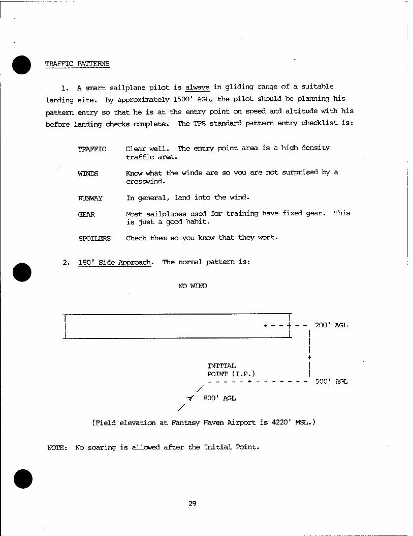
2. 180° Side Approach. The normal pattern is:
NO WIND
* _ _ | _ _ 200' AGL
J L I I I +
INITIAL I POINT (I.P.) I -► 500' AGL
/ -f 800' AGL
/
(Field elevation at Fantasy Haven Airport is 4220' MSL.)
NOTE: No soaring is allowed after the Initial Point.
29
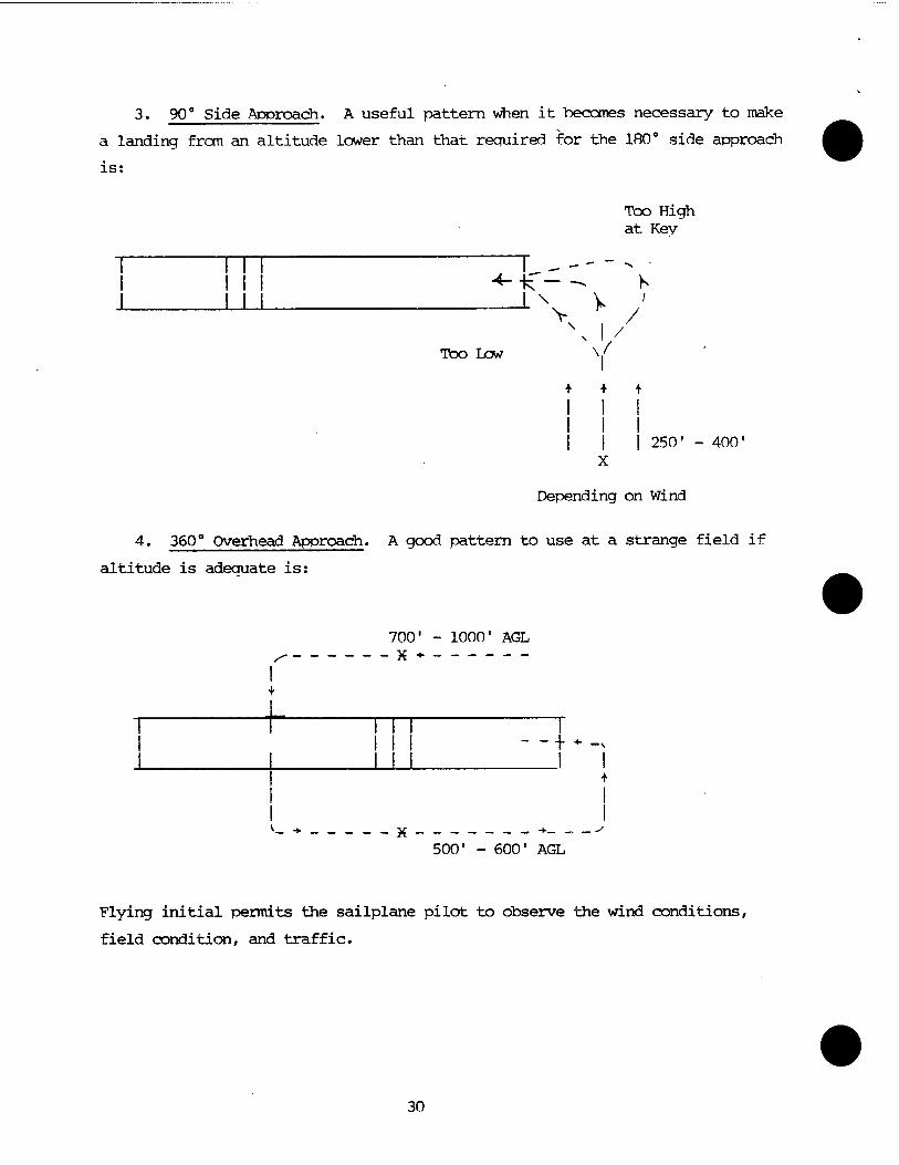
3. 90° Side Approach. A useful pattern when it becomes necessary to make
a landing from an altitude lower than that required for the 180° side approach
is:
Too High at Key
—x V Too Low V
+ + +
j j I 250' - 400' X
Depending on Wind
4. 360° Overhead Approach. A good pattern to use at a strange field if
altitude is adequate is:
700' - 1000' AGL
i "1 m r I Ml --+«■-
I I
500' - 600' AGL
Flying initial permits the sailplane pilot to observe the wind conditions,
field condition, and traffic.
30
LANDING
1. Using Spoilers. The proper sailplane approach is close in and high,
requiring use of approximately 50% spoilers to maintain the correct glide
slope. Although the sailplane can be landed without use of flaps or spoilers
by proper adjustment of the base leg to control touchdown point, most pilots
prefer to approach slightly high with some altitude as a reserve against sink
conditions throughout the pattern. Spoilers should be tested for operation
while on downwind or base leg of the pattern so that they can be depended on
for adjustment of the approach. One spoiler technique is to use half spoiler
on the approach, controlling the glidepath by treating the spoiler handle much
as a throttle, by pulling back to steepen the approach or pushing forward to
flatten the approach. Another technique is to approach as if to land long
without spoilers, and when sure of reaching the touchdown point, applying
spoilers. Normal final approach speed is 55 (KIAS/MPH) + 1/2 of headwinds +
gust. Spoilers increase the stall speed, drag, and steepen the angle of
approach.
2. Using a Forward Slip. A forward slip can be used for altitude
correction throughout the pattern. Remember that the airspeed indication is
not reliable during the slip maneuver. When recovering from the slip, the
sailplane should be flown nose low to prevent an inadvertent stall and to
ensure a proper airspeed. If the nose is held too low during the slip,
effectiveness is reduced. Using spoilers is normally a better technique for
shortening the glide to a landing so all slips should be done with full
spoilers out.
Constant airspeed is held on final approach until within approximately 25
feet from the ground. At this point, the sailplane is slowly rounded out and
flown onto the ground. The sailplane is not flared or stalled to touchdown as
in power aircraft landings. Touchdown should be made at 40-45 KIAS/MPH, but
not so high a speed as to cause long float distances. Stalling a sailplane at
an altitude of two or more feet will result in a drop-in landing. Since most
sailplanes have no shock absorbing landing gear, damage to the aircraft is a
strong possibility. In any crosswind, make sure that you do not touchdown
with any crab.
31
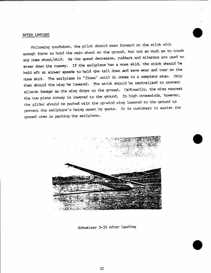
AFTER LANDING
Following touchdown, the pilot should ease forward on the stick with
enough force to hold the main wheel on the ground, but not so much as to touch
any nose wheel/skid. As the speed decreases, rudders and ailerons are used to
steer down the runway. If the sailplane has a nose skid, the stick should be
held aft at slower speeds to hold the tail down and save wear and tear on the
nose skid. The sailplane is "flown" until it cones to a complete stop. Only
then should the wing be lowered. The stick should be neutralized to prevent
aileron damage as the wing drops to the ground. Ordinarily, the wing nearest
the tow plane runway is lowered to the ground. In high crosswinds, however,
the glider should be parked with the up-wind wing lowered to the ground to
prevent the sailplane's being upset by gusts. It is customary to assist the
ground crew in parking the sailplane.
Schweizer 2-33 After Landing
32
REFERENCES
1. Ann and Lome Welch, The Story of Gliding, London, Jon Murray, 1965.
2. Ann and Lome Welch, The Soaring Pilot, London, Jon Murray, 1960.
3. Richard Miller, Without Visible Means of Support, Los Angeles, Parker & Son, 1967.
4. Philip Wills, On Being a Rird, London, Sailflying Press Ltd.
5. R. C. Stafford Allen, Theory of Flight for Gliding Pilots, London, Oliver and Boyd, 1962.
6. The Soaring Society of America, Inc., American Soaring Handbook, Vol I, II, IV, V, VI, VII, Los Angeles
7. Richard H. Johnson, "Sailplane Flight-Test Performance Measurement," Soaring, Vol 32, April 1968, pp 10-16.
8. Bernard Paiewonsky, "A Flight Test Program for Examining Sailplane Lateral-Directional Stability and Control," Soaring, Vol 33, February 1969, pp 8-26.
9. Wolfgang Langewiesche, "Soaring is Now For-Sale," Soaring, Vol 32, August 1968, pp 8-26.
10. Schweizer Aircraft Corporation, Soaring School Manual, Box 147, Elmira, NY 14902, 1967.
33
APPENDIX
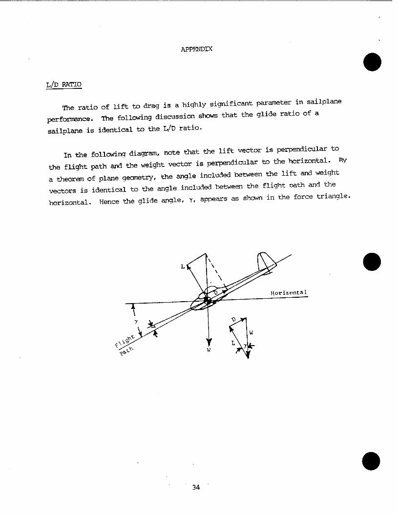
L/D RATIO
The ratio of lift to drag is a highly significant parameter in sailplane
performance. The following discussion shows that the glide ratio of a
sailplane is identical to the L/D ratio.
in the following diagram, note that the lift vector is perpendicular to
the flight path and the weight vector is perpendicular to the horizontal. By
a theorem of plane geometry, the angle included between the lift and weight
vectors is identical to the angle included between the flight path and the
horizontal. Hence the glide angle, y, appears as shown in the force triangle.
34
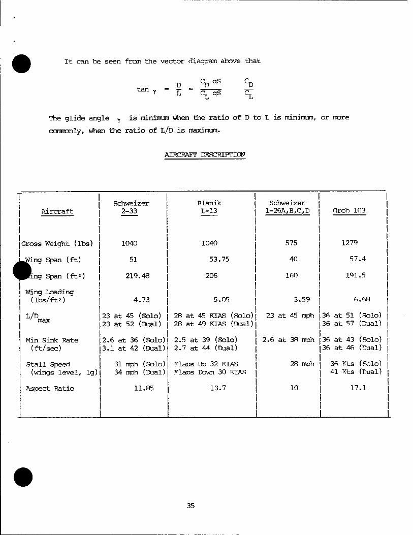
It can be seen fron the vector diagram above that
tan D CDqS
y L C_ qS
The glide angle Y ^s minimum when the ratio of D to L is minimum, or more
commonly, when the ratio of L/D is maximum.
AIRCRAFT DESCRIPTION
T Schweizer Rlanik | Schweizer
| Aircraft 2-33 | L-13 | 1-26A,B,C,D 1 Grob 103 |
[Gross Weight (lbs) 1040 1040 575 1279 |
^^7ing Span (ft) 51 53.75 40 57.4 |
^Pftng Span (ft*) 219.48 206 160 191.5 |
1 Wing Loading | (lbs/ft*) 4.73 5.05 3.59 6.68 |
1 L/D 23 at 45 (Solo) 28 at 45 KIAS (Solo) 23 at 45 mph 36 at 51 (Solo) | max
23 at 52 (Dual) 28 at 49 KIAS (Dual) 36 at 57 (Dual) |
1 Min Sink Rate 2.6 at 36 (Solo) 2.5 at 39 (Solo) 2.6 at 38 mph 36 at 43 (Solo) | | (ft/sec) 3.1 at 42 (Dual) 2.7 at 44 (Dual) 36 at 46 (Dual) |
| Stall Speed 31 mph (Solo) Flaps Up 32 KTAS 28 mph 36 Kts (Solo) | 1 (wings level, ig) 34 mph (Dual) Flaps Down 30 KIAS 41 Kts (Dual) ]
1 Aspect Ratio 11.85 13.7 10 17.1 |
35