tagoram: real-time tracking of mobile rfid tags …xli/paper/conf/tagoram-mobicom.pdf · tagoram:...
TRANSCRIPT
Tagoram: Real-Time Tracking of Mobile RFID Tags to HighPrecision Using COTS Devices
Lei Yang∗, Yekui Chen∗, Xiang-Yang Li∗,†, Chaowei Xiao∗, Mo Li‡, Yunhao Liu∗
∗School of Software and TNLIST, Tsinghua University, China†Department of Computer Science, Illinois Institute of Technology, USA
‡School of Computer Engineering, Nanyang Technological University, Singapore
[email protected], [email protected], [email protected],[email protected], [email protected], [email protected]
ABSTRACT
In many applications, we have to identify an object and then locatethe object to within high precision (centimeter- or millimeter-level).Legacy systems that can provide such accuracy are either expensiveor suffering from performance degradation resulting from variousimpacts, e.g., occlusion for computer vision based approaches.
In this work, we present an RFID-based system, Tagoram, forobject localization and tracking using COTS RFID tags and read-ers. Tracking mobile RFID tags in real time has been a dauntingtask, especially challenging for achieving high precision. Our sys-tem achieves these three goals by leveraging the phase value of thebackscattered signal, provided by the COTS RFID readers, to es-timate the location of the object. In Tagoram, we exploit the tag’smobility to build a virtual antenna array by using readings from afew physical antennas over a time window. To illustrate the basicidea of our system, we firstly focus on a simple scenario where thetag is moving along a fixed track known to the system. We pro-pose Differential Augmented Hologram (DAH) which will facili-tate the instant tracking of the mobile RFID tag to a high precision.We then devise a comprehensive solution to accurately recover thetag’s moving trajectories and its locations, relaxing the assumptionof knowing tag’s track function in advance.
We have implemented the Tagoram system using COTS RFIDtags and readers. The system has been tested extensively in thelab environment and used for more than a year in real airline ap-plications. For lab environment, we can track the mobile tags inreal time with a millimeter accuracy to a median of 5mm and7.29mm using linear and circular track respectively. In our year-long large scale baggage sortation systems deployed in two air-ports, our results from real deployments show that Tagoram canachieve a centimeter-level accuracy to a median of 6.35cm in thesereal deployments.
Categories and Subject Descriptors
C.2 [Computer Systems Organization]: Computer Communica-tions Networks
Permission to make digital or hard copies of all or part of this work for personal or
classroom use is granted without fee provided that copies are not made or distributed
for profit or commercial advantage and that copies bear this notice and the full citation
on the first page. Copyrights for components of this work owned by others than the
author(s) must be honored. Abstracting with credit is permitted. To copy otherwise, or
republish, to post on servers or to redistribute to lists, requires prior specific permission
and/or a fee. Request permissions from [email protected].
MobiCom’14, September 07-11, 2014, Maui, Hawaii, USA.
Copyright is held by the owner/author(s). Publication rights licensed to ACM.
ACM 978-1-4503-2783-1/14/09 ...$15.00.
http://dx.doi.org/10.1145/2639108.2639111 .
Keywords
RFID; Tracking; Localization; DAH; Tagoram
1. INTRODUCTIONRadio Frequency IDentification (RFID) is a rapidly developing
technology which uses RF signals for automatic identification ofobjects. One of its most promising applications is to track themobile objects accurately. Many applications would benefit fromhigher tracking accuracy. For example, supermarkets can deeplymine the consumers’ shopping habits by monitoring the items’ tra-jectories. Similarly, it is useful to conduct automatic recognitionof complex multi-player behaviors through the tagged football ina world-wide game. Plenty of new battery-free human-machineinteractive device can be developed using the tags, like writing let-ters in the air by attaching a tag on a finger. Exact tracking infor-mation is also indispensable for some emerging RFID applicationslike automated customer checkout. Today’s robots routinely re-place human labor in assembly tasks. It has been of a great interestin both the robotics academic community and industry to enablerobot search for a desired object, pick it up, fetch and delivery itfrom a assembly lines. These tasks require tracking the object tocm-level and even mm-level accuracy [1]. Another typical appli-cation is the object sortation. Slightest tracking error may result inincorrect baggage sortation and delivery in airport. According tothe report of our partner airline operator, Hainan Airline, over 90%of its baggage losses are due to the tracking and sorting error onthe airport conveyors. In this paper, we target at the problem oftracking mobile RFID tags at high precision (cm- and mm- level),in order to meet the needs of challenging applications.
Existing RFID localization techniques cannot be directly applieddue to the following reasons. First, to the best of our knowledgethere are seldom reported approaches that can achieve high pre-cision of localization accuracy, especially for mobile tags. Sec-ond, many RFID localization approaches (e.g., [2–10]) rely on pre-deployed reference tags for accurate calibration, which is infeasi-ble for a tracking system spanning a long pipeline (e.g., the sorta-tion line in the airport). Third, the mobile tag experiences fast-changing environment with non-ideal communication conditionssuch as multipath reflections of RF signals, varied orientation oftags, etc., which fail most existing localization techniques for theirassumption on static communication environment.
In this paper, we design Tagoram, which exploits the phase valueof received signal for real-time tracking of mobile tags with a high
precision. We observe that the COTS RFID products support fine-grained resolution in detecting the phase of received RF signals,
i.e., with accuracy ≈ 0.0015 radians. This accuracy offers an op-portunity to locate the object with accuracy of millimeter-level dis-placement. Developing a practical system out of the basic principle,however, entails substantial challenges. First, the RF phase mea-surement is affected by the basic thermal noise at the receiver side,which results in the practically measured RF phase a random vari-able following Gaussian distribution. How to derive a definite andaccurate tracking result from the indefinite phase measurement re-mains challenging. Second, the device diversity in phase measure-ment introduces extra phase shifts we call “diversity term”. Differ-ent RFID tags or readers have different diversity terms. Prior cal-ibration of all tags and readers is impractical and computationallyinfeasible and we need to carefully sidestep the problem. Third, thefast changing environment makes the phase measurement a com-plex result mixing RF propagation through the line-of-sight (LOS)with the None LOS. It is hard to separate them and thus non-trivialto accurately derive the tag position. We propose a hologram basedapproach, called Tagoram, to tackle above challenges using COTSRFID tags and readers with a few physical antennas. We build anRF phase hologram with observations from different reader anten-nas and at different time of scan. To tackle the challenges of mo-bile tags, we assume the antennas moving to the opposite directionrelative to the mobile tag. Such fictitious reader “mobility” offersindividual RF phase observations from different positions relativeto the tag, and they form an RF hologram as if they were obtainedfrom a virtual antenna array. If the tag movement velocity and itsmoving track is known in advance, the positions of the antenna ar-ray relative to the tag can be determined. We can thus rely on theinstant hologram to derive the initial position of the tag and thusprecisely track the tag movement. In order to tackle previouslyidentified challenges we further develop Differential AugmentedHologram (DAH) approach from the naive one. The details willbe elaborated in §4. In §5, we then relax the assumption that weknow the tag moving track in advance and devise a technique toaccurately recover the tag movement from antenna observations.We first identify a series of candidate tag moving paths using thecontinuously estimated tag velocity from the antenna array. ThenDAH is extended to identify the one with the highest likelihoodof generating the observed RF phases. To enable real-time local-ization and tracking, we propose several techniques to speedup thecomputation of hologram.
Summary of results: We implement Tagoram using a COTSreader equipped with 4 antennas (see §6). We first conduct exten-sive testbed experiments in indoor environment with all communi-cation irregularities and compare with RSS [2], OTrak [3], PinIt [6]and BackPos [9] in §7. The tags are attached to objects moving ondifferent tracks. In our result, Tagoram achieves mm-level accu-racy to a median of 5mm and 7.29mm under linear and circulartrack respectively using DAH, offering about 82×, 21×, 16× and55× improvement compared to above four methods, in a control-lable case where the track is known and without need of referencetags. Even in an uncontrollable case with 4 antennas, Tagoramcan still achieve centimeter accuracy to a median error distance of12.3cm. In addition, Tagoram adopts a strategy of incrementalcomputation to generate the final hologram. Our experiment showsthat it only takes about 2.5 seconds to get a high accuracy. For mostof real time application, especially for the control of mechanicalsystem like sorting or assembly system, it is within an acceptablelevel.
We then perform large scale trial studies in tracking RFID taggedbaggages with real airport baggage sortation systems, presented in§8. We develop a customized device with multi-antenna equipedRFID reader, called TrackPoint. Ten TrackPoints are deployed
!"#$"%&
'()"((#
*#+
,#-./-#))"%&0#1"
θTAG
2%3"()#)34(
d
θTλ
θR
θ = (2π
λ× 2d+ θT + θR + θTAG
︸ ︷︷ ︸
diversity term
) mod 2π
Figure 1: Backscatter communication
for automatic baggage sortation in two of the busiest airports inChina, Beijing Capital International Airport (BCIA T1) and SanyaPhoenix International Airport (SPIA). Long term pilot studies havebeen launched since January 2013. The trial studies have by farconsumed 110,000 RFID tags. 12 billion traced records were col-lected during the study. In this practical application environmentmillions of baggages were conveyed and there exist various metaltransport vehicles that create rich multipath signal reflections. Thepractical tracking results show that Tagoram achieves a centimeter-level accuracy to a median error distance of 6.35cm.
Contribution: To summarize, we made the following contribu-tions: First, to best of our knowledge, Tagoram is the first systemthat can successfully limit the negative impact of the multipath phe-nomena and the phase measurement error (caused by thermal noiseand tag diversity). Second, we design and implement the Tago-ram system, purely based on COTS RFID products which makesthe fast adoption and deployment possible. Third, we systemati-cally evaluate the system under indoor environment and two sort-ing environment at two airports. As a result, Tagoram can providereal-time tracking of mobile tags with a high precision.
The rest of the paper is organized as follows. We present thebackground and preliminary studies in §2. The main design ofTagoram is overviewed in §3. We present the details of Tagoramfor controlled moving trajectory using DAH in §4 and uncontrolledtrajectory in §5. The implementation of Tagoram is described in §6and evaluated in §7 and §8. We review the related work in §9 andconclude our work in §10.
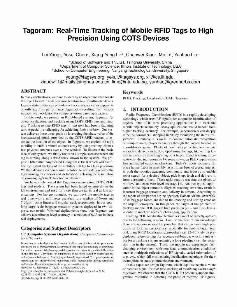
2. BACKGROUNDPassive RFID system communicates using a backscatter radio
link. The tags, no battery equipped, purely harvest energy fromthe reader’s signal. Fig. 1 illustrates a conceptual diagram of thebackscatter communication between a reader and a passive tag.The wireless signal from the reader’s antenna induces a voltageon the tag’s antenna and the radiated wave makes its way back tothe reader’s antenna, induces a voltage, and therefore produces asignal that can be detected: a backscatter signal. The tag modulatesits data on the backscatter signals using ON-OFF keying throughchanging the impedance on its antenna. A COTS reader is usuallyconnected to 4 directional antennas. These antennas transmit sig-nals alternatively in exclusive time-slots to avoid the reader colli-sion. The tag orientation is defined as the angle between the readerantenna’s polarization direction and the tag’s antenna.
RF phase: The RF phase is a common parameter supported byCOTS readers. Suppose d is the distance between the reader an-tenna and the tag, the signal traverses a total distance of 2d backand forth in backscatter communication. Besides the RF phase ro-tation over distance, the reader’s transmitter, the tag’s reflection
characteristic, and the reader’s receiver circuits will all introducesome additional phase rotations, denoted as θT , θTAG and θR re-spectively. The total phase rotation [11] output by the reader canbe expressed as
{θ =
(2πλ
× 2d+ c)mod 2π
c = θT + θR + θTAG
(1)
where λ is the wavelength. The term c is called diversity term,which is related to the hardware characteristics. The phase is a pe-riodic function with period 2π radians which repeats every λ/2 inthe distance of backscatter communication. Most modern COTSRFID readers, e.g. ImpinJ R420 [12], are able to report the θ asa phase difference of transmitted and received signal. One RFphase estimate is output each time a tag that is successfully in-terrogated, depending on the individual antenna and channel. Atypical UHF reader has 16 channels working at 920 ∼ 926 MHzISM band. Thus, the resolution can be achieved 0.0015 radiansin theory, thereby offering ≈ 320mm ∗ 0.0015/(4 × 3.14) =0.038mm ranging resolution 1. Such ultra-high resolution makesthe RF phase an attractive indicator for mm-level localization andtracking.
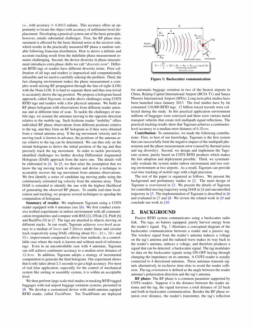
Challenges and empirical studies: (i) The phase estimate is de-rived from the received signal where the thermal noise from readerreceiver is always present, leading to measurement errors. We con-duct an empirical studies over 100 tags with environment temper-ature from 0◦ to 40◦C, various frequencies (920 ∼ 926MHz) in-cluding 16 channels, and RSS from -70 to -30dbm (different orien-tations). One set of the results measured at the 5th channel is de-picted in Fig. 2(a). These experiments suggest that the phase mea-surement results contain random errors, following a typical Gaus-sian distribution with a standard deviation of 0.1 radians. In thefollowing sections, we will consider the phase measurement as aGaussian random variable instead of an accurate value. (ii) To val-idate the existence of tag’s diversity on RF phase. We place 70 tagsat a same position in turn. Each tag is interrogated for 100 timesand the average value is reported in Fig. 2(b). We observe that themeasured phase values are distributed among 0.3007 ∼ 5.8438 ra-dians. Such an observation suggests that the tag’s diversity takesimpact on phase measurement and cannot be ignored in practice.We also perform the Kolmogorov-Smirnov test (KS-test) to studytheir predictability. These values pass the test to be verified overa uniform distribution with 0.5 significant level, which means thatthe tag diversity is hard to infer. In summary, both the thermal noiseand tag diversity challenge the phase measurement and further af-fect the tracking accuracy, which were not fully studied previously.
3. TAGORAM OVERVIEWTagoram is an RFID-based practical tracking system towards
mobile objects. As a running example, we mainly present the sys-tem in the context of conveyor or assembly task. Tagoram’s tech-nique applies to a variety of tracking applications, including robotmanipulation.
3.1 ScopeUltra-low cost of UHF tags (5-10 cents each) become the pre-
ferred choice of many industry applications. Following the com-mon practices, we concentrate on the tracking of UHF tags in thispaper. Today’s COTS readers have an operating range of around10m [12]. In this work, we focus on locating and tracking mo-bile tags that are not moving at a high speed. As presented in [13]
1320mm is the average wavelength among 16 channels.
3.45 3.5 3.55 3.6 3.65 3.70
10
20
30
40
50
60
Phase
Count(
#)
(a) Phase distribution
10 20 30 40 50 60 700
1
2
3
4
5
6
7
Tag#
Measure
d P
hase (
radia
n)
(b) Tag diversity
Figure 2: Empirical studies on measured RF phase. (a) Thephase obeys a Gaussian distribution. (b) The diversity takes animpact on measured phase.
(we had similar observations in our experiments) the system suffersfrom serious packet loss when the tag moves with a high speed, re-sulting that the tag even cannot be interrogated. Thus, our systemconsiders the case where tags move with a relative low speed.
3.2 Problem DefinitionWe consider the mobile RFID tag tracking applications, where
the tags move within a surveillance region monitored by M RFantennas, denoted as A = {A1, A2, · · · , AM}, with known loca-tions. These antennas are connected to the same reader and sched-uled at different time slots in a round robin approach [14]. Forbrevity, we use Am to indicate the mth antenna as well as its co-ordinate. Our approach is mainly presented in 2D surveillance re-gion, but it can be easily extended to 3D space (discussed later in§4.3). The surveillance plane is divided into grids, with W rowsand L columns. Suppose the reader has taken N rounds of anten-nas schedule, there are total M × N phase measurements so far.Formally, we use a matrix Θ to denote these measurements.
Θ =
θ1,1 · · · θ1,N...
......
θM,1 · · · θM,N
(2)
The element θm,n denotes the nth phase value measured by themth antenna. Besides the measured values, we also record the timestamps when the phases are measured:
T =
t1,1 · · · t1,N...
......
tM,1 · · · tM,N
= t0 +
∆1,1 · · · ∆1,N
......
...∆M,1 · · · ∆M,N
(3)The element tm,n is the time that the tag is interrogated for nth
time by the mth antenna. The time matrix T is normalized basedon the time t0. No constraint is put on choice of t0 and we always
A1
A2
A1,1 A1,2 A1,3 A1,4
A2,1 A2,2 A2,3 A2,4
(t1,2, θ1,2)(t1,1, θ1,1) (t1,3, θ1,3) (t1,4, θ1,4)
(t2,1, θ2,1) (t2,2, θ2,2) (t2,3, θ2,3)(t2,4, θ2,4)
f(t1,1)
f(t2,1)
f(t1,2)f(t1,4) f(t1,3)
f(t2,2)f(t2,3)f(t2,4)
V
Figure 3: Virtual antenna matrix. The target tag moves fromright to left. Total 8 virtual antennas are constructed.
choose the time when the tag is firstly interrogated as the base time,i.e. t0 = min{tm,n}, throughout this paper. The ∆m,n is the timedifference, i.e. ∆m,n = (tm,n − t0). We formally define thetracking problem as follows:
PROBLEM 1. Given Θ, T and A, how to find the tag’s trajec-
tory coordinates, i.e. {f(t1,1), f(t1,2), · · · , f(tM,N )}, at an arbi-
trary interrogated time? Here f(t) is the time-dependent trajectory
function outputting the tag’s coordinate at time t.
The trajectory is a function of time series indicating the trace that amoving object follows through space, which emphasizes the time-space relationship. To avoid the confusion of relevant concept, wedefine another term, track, indicating the path along which the tagmight move. The track is a geometric function, which may formu-late a close-loop conveyor belt, a passageway through the building,or a highway based on the road. The track function may be com-posed by a complex piecewise function but irrelevant to time.
3.3 SolutionIn this paper, we propose a holistic system, Tagoram, to address
the instant tag tracking problem. Tagoram decomposes it into twostages.
• Controllable Case: First, we consider a simplified case wherethe tags move along a known track with a constant speed. This casemostly occurs at a conveyor belt or assembly line where the objectsare conveyed by a predefined track. Then the trajectory functioncan be expressed as:
f(t) = f(t0) +
∫ t
t0
~V (t)dt (4)
where ~V (t) is the speed function. Note the trajectory function mayfollow a more complex model but it can be always abstracted as theabove equation. The f(t0) is termed as the initial position wherethe tag is interrogated at time t0. As long as the tag’s positionat time t0 is estimated, its location at an arbitrary time t can beinferred using Equation 4 in combination with the track function.Thus, the main task in this case is to locate the tag’s initial positionf(t0). We present our solution in §4.• Uncontrollable Case: We then consider a general case where
no prior knowledge about the tag’s moving track is known by oursystem. Thanks to the highly efficient anti-collision capability, thetag can be observed at a high frequency. We approximate its ir-regular and unpredictable trajectory at run time by exploiting thedifferentials between consecutive phase values. Then we use theapproach introduced in §5 to identify a set of potential trajectoriesand converting the problem of selecting the optimal trajectory intoa task in first stage.
eJh(X,A1,1)−θ1,1
eJh(X,A1,2)−θ1,2
eJh(X,AM,N )−θM,N
(a) Waves reinforced
eJh(X,A1,1)−θ1,1
eJh(X,A1,2)−θ1,2
eJh(X,AM,N )−θM,N
eJh(X,A1,3−θ1,3)
(b) Waves canceled out
Figure 4: Superimposing the observations from different an-
tennas.
4. MOVEMENT WITH KNOWN TRACKIn this section, we discuss the first case in context of conveyor
or assembly with known track function and constant speed ~V (t) tofind out the mobile tag’s trajectory.
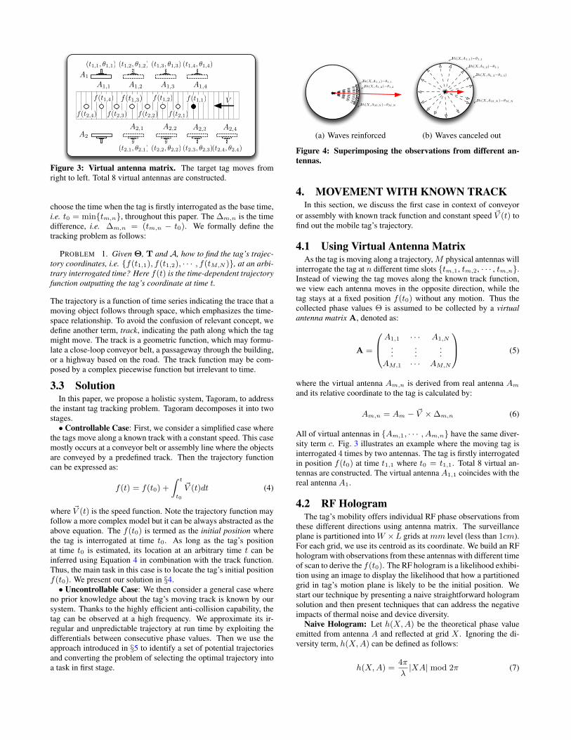
4.1 Using Virtual Antenna MatrixAs the tag is moving along a trajectory, M physical antennas will
interrogate the tag at n different time slots {tm,1, tm,2, · · · , tm,n}.Instead of viewing the tag moves along the known track function,we view each antenna moves in the opposite direction, while thetag stays at a fixed position f(t0) without any motion. Thus thecollected phase values Θ is assumed to be collected by a virtual
antenna matrix A, denoted as:
A =
A1,1 · · · A1,N
......
...AM,1 · · · AM,N
(5)
where the virtual antenna Am,n is derived from real antenna Am
and its relative coordinate to the tag is calculated by:
Am,n = Am − ~V ×∆m,n (6)
All of virtual antennas in {Am,1, · · · , Am,n} have the same diver-sity term c. Fig. 3 illustrates an example where the moving tag isinterrogated 4 times by two antennas. The tag is firstly interrogatedin position f(t0) at time t1,1 where t0 = t1,1. Total 8 virtual an-tennas are constructed. The virtual antenna A1,1 coincides with thereal antenna A1.
4.2 RF HologramThe tag’s mobility offers individual RF phase observations from
these different directions using antenna matrix. The surveillanceplane is partitioned into W ×L grids at mm level (less than 1cm).For each grid, we use its centroid as its coordinate. We build an RFhologram with observations from these antennas with different timeof scan to derive the f(t0). The RF hologram is a likelihood exhibi-tion using an image to display the likelihood that how a partitionedgrid in tag’s motion plane is likely to be the initial position. Westart our technique by presenting a naive straightforward hologramsolution and then present techniques that can address the negativeimpacts of thermal noise and device diversity.
Naive Hologram: Let h(X,A) be the theoretical phase valueemitted from antenna A and reflected at grid X . Ignoring the di-versity term, h(X,A) can be defined as follows:
h(X,A) =4π
λ|XA| mod 2π (7)
0 50 100 150 2000
50
100
150
X(cm)
Y(c
m)
0.2
0.4
0.6
0.8
1
050
100150
200
050
100150
0
0.5
1
X(cm)Y(cm)
Norm
aliz
ed lik
elih
ood
(a) Naive Hologram
0 50 100 150 2000
50
100
150
X(cm)
Y(c
m)
0.2
0.4
0.6
0.8
1
050
100150
200
0
50
100
150
0
0.5
1
X(cm)Y(cm)
Norm
aliz
ed lik
elih
ood
(b) Augmented Hologram
0 50 100 150 2000
50
100
150
X(cm)
Y(c
m)
0.2
0.4
0.6
0.8
1
0 50 100 150 200050100
1500
0.2
0.4
0.6
0.8
1
X(cm)Y(cm)
Norm
aliz
ed lik
elih
ood
(c) Differential Augmented Hologram
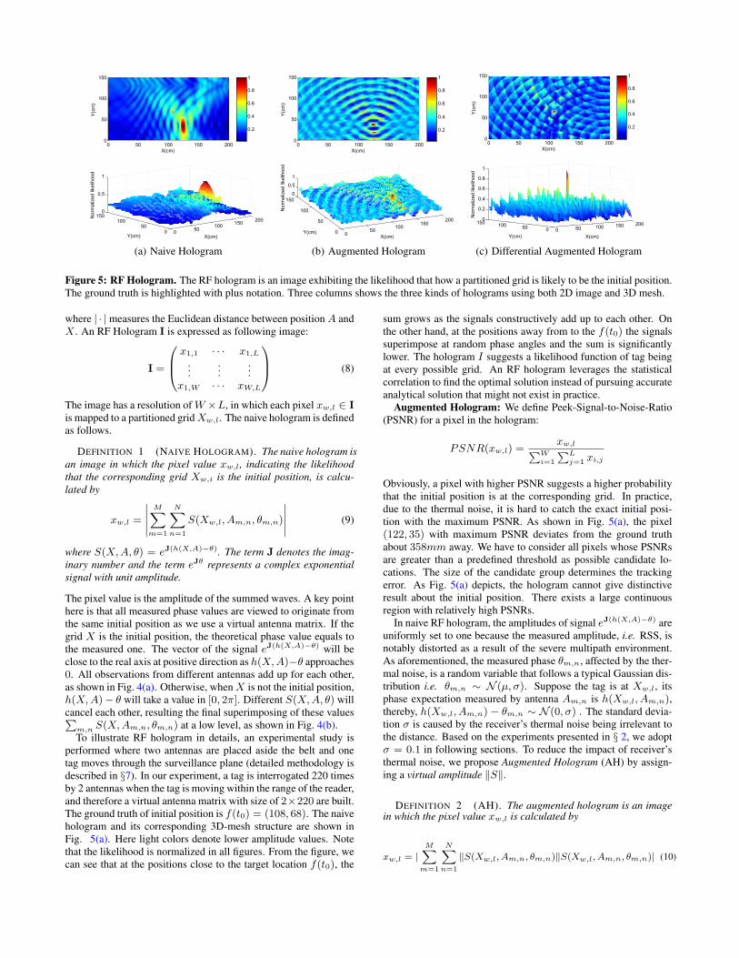
Figure 5: RF Hologram. The RF hologram is an image exhibiting the likelihood that how a partitioned grid is likely to be the initial position.The ground truth is highlighted with plus notation. Three columns shows the three kinds of holograms using both 2D image and 3D mesh.
where | · | measures the Euclidean distance between position A andX . An RF Hologram I is expressed as following image:
I =
x1,1 · · · x1,L
......
...x1,W · · · xW,L
(8)
The image has a resolution of W ×L, in which each pixel xw,l ∈ I
is mapped to a partitioned grid Xw,l. The naive hologram is definedas follows.
DEFINITION 1 (NAIVE HOLOGRAM). The naive hologram is
an image in which the pixel value xw,l, indicating the likelihood
that the corresponding grid Xw,i is the initial position, is calcu-
lated by
xw,l =
∣∣∣∣∣
M∑
m=1
N∑
n=1
S(Xw,l, Am,n, θm,n)
∣∣∣∣∣ (9)
where S(X,A, θ) = eJ(h(X,A)−θ). The term J denotes the imag-
inary number and the term eJθ represents a complex exponential
signal with unit amplitude.
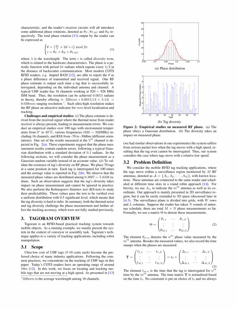
The pixel value is the amplitude of the summed waves. A key pointhere is that all measured phase values are viewed to originate fromthe same initial position as we use a virtual antenna matrix. If thegrid X is the initial position, the theoretical phase value equals tothe measured one. The vector of the signal eJ(h(X,A)−θ) will beclose to the real axis at positive direction as h(X,A)−θ approaches0. All observations from different antennas add up for each other,as shown in Fig. 4(a). Otherwise, when X is not the initial position,h(X,A)− θ will take a value in [0, 2π]. Different S(X,A, θ) willcancel each other, resulting the final superimposing of these values∑
m,n S(X,Am,n, θm,n) at a low level, as shown in Fig. 4(b).To illustrate RF hologram in details, an experimental study is
performed where two antennas are placed aside the belt and onetag moves through the surveillance plane (detailed methodology isdescribed in §7). In our experiment, a tag is interrogated 220 timesby 2 antennas when the tag is moving within the range of the reader,and therefore a virtual antenna matrix with size of 2×220 are built.The ground truth of initial position is f(t0) = (108, 68). The naivehologram and its corresponding 3D-mesh structure are shown inFig. 5(a). Here light colors denote lower amplitude values. Notethat the likelihood is normalized in all figures. From the figure, wecan see that at the positions close to the target location f(t0), the
sum grows as the signals constructively add up to each other. Onthe other hand, at the positions away from to the f(t0) the signalssuperimpose at random phase angles and the sum is significantlylower. The hologram I suggests a likelihood function of tag beingat every possible grid. An RF hologram leverages the statisticalcorrelation to find the optimal solution instead of pursuing accurateanalytical solution that might not exist in practice.
Augmented Hologram: We define Peek-Signal-to-Noise-Ratio(PSNR) for a pixel in the hologram:
PSNR(xw,l) =xw,l∑W
i=1
∑L
j=1 xi,j
Obviously, a pixel with higher PSNR suggests a higher probabilitythat the initial position is at the corresponding grid. In practice,due to the thermal noise, it is hard to catch the exact initial posi-tion with the maximum PSNR. As shown in Fig. 5(a), the pixel(122, 35) with maximum PSNR deviates from the ground truthabout 358mm away. We have to consider all pixels whose PSNRsare greater than a predefined threshold as possible candidate lo-cations. The size of the candidate group determines the trackingerror. As Fig. 5(a) depicts, the hologram cannot give distinctiveresult about the initial position. There exists a large continuousregion with relatively high PSNRs.
In naive RF hologram, the amplitudes of signal eJ(h(X,A)−θ) areuniformly set to one because the measured amplitude, i.e. RSS, isnotably distorted as a result of the severe multipath environment.As aforementioned, the measured phase θm,n, affected by the ther-mal noise, is a random variable that follows a typical Gaussian dis-tribution i.e. θm,n ∼ N (µ, σ). Suppose the tag is at Xw,l, itsphase expectation measured by antenna Am,n is h(Xw,l, Am,n),thereby, h(Xw,l, Am,n) − θm,n ∼ N (0, σ) . The standard devia-tion σ is caused by the receiver’s thermal noise being irrelevant tothe distance. Based on the experiments presented in § 2, we adoptσ = 0.1 in following sections. To reduce the impact of receiver’sthermal noise, we propose Augmented Hologram (AH) by assign-ing a virtual amplitude ‖S‖.
DEFINITION 2 (AH). The augmented hologram is an imagein which the pixel value xw,l is calculated by
xw,l = |M∑
m=1
N∑
n=1
‖S(Xw,l, Am,n, θm,n)‖S(Xw,l, Am,n, θm,n)| (10)
where
‖S(X,A, θ)‖ = 2× F (|h(X,A)− θ|; 0, 0.1)
F (x;µ, σ) =1
σ√2π
∫ ∞
x
exp
(− (t− µ)2
2σ2
)dt
and F (x;µ, σ) is the cumulative probability function of Gaussian
distribution N (µ, σ).
The assigned amplitude ‖S(Xw,l, Am,n, θm,n)‖ is the cumulativeprobability that the measured phase is emitted from Am,n and backscat-tered at grid Xw,l. Doing so enhances the amplitude of these waveswith higher probability and weakens others. In effect, those pixelswhose measured phase values are very close to theoretical values,are augmented in the hologram. Fig. 5(b) depicts the augmentedhologram using the same observed data as those in Fig. 5(a). Wesee that AH breaks up the large continuous region that has higherPSNRs into several points and reinforces the initial position.
Differential Augmented Hologram: From the augmented holo-gram, we find that there still exist some candidate positions withhigher PSNR, distributed around the ground truth. These few spotsmake the tracking error around 200mm. We believe these ambi-guities are caused by the device diversity across different antennas.The measured phase θ equals to h(X,A) + c. Assume tag’s initialposition is at grid T , then
S(X,A, θ) = eJ(h(X,A)−(h(T,A)+c))
In theory, the maximum amplitude should happen when X = T .In practice, the energy is spread across grids X that h(X,A) =h(T,A) + c. As each antenna takes a different impact on the c, theuncalibrated θ violates our basic assumption that the phase mea-sured by each virtual antenna would originate from the initial posi-tion. To eliminate such influence caused by the diversity term, wefurther propose Differential Augmented Hologram (DAH) redefin-ing a new virtual signal S.
DEFINITION 3 (DAH). The differential augmented hologramis an image in which the pixel value is calculated by
xw,l =
∣
∣
∣
∣
∣
M∑
m=1
N∑
n=1
‖S(Xw,l, Am,n, θm,n)‖S(Xw,l, Am,n, θm,n)
∣
∣
∣
∣
∣
(11)
where
S(Xw,l, Am,n, θm,n) = eJθdif
‖S(Xw,l, Am,n, θm,n)‖ = 2× F (|θdif|; 0, 0.1×√2)
θdif = (h(Xw,l, Am,n)− θm,n)− (h(Xw,l, Am,1)− θm,1))
The virtual signal eJθdif is constructed using the difference ofphase difference. We reconstruct the virtual signal S. Note that(h(Xw,l, Am,n)− θm,n)− (h(Xw,l, Am,1)− θm,1)= (h(Xw,l, Am,n) − (h(T,Am,n) + c)) − (h(Xw,l, Am,1) −(h(T,Am,1)+c)) = h(Xw,l, Am,n)−h(T,Am,n)+h(T,Am,1)−h(Xw,l, Am,1). A key observation here is that the diversity termc is eliminated through subtracting the measured phase differencefrom the theoretical difference between the Am,n and Am,1. Sinceeach row of virtual antennas Am,n is derived from a same phys-ical antenna Am and each row of phase measurements θm,n aretaken by the same antenna Am, so the subtraction is treated dif-ferently for different rows. For each row, we choose the first vir-tual antenna as the calibration base. In addition, the θdif intro-duces subtraction of two random variables, θm,n and θm,1. Noticethat (h(Xw,l, Am,n) − θm,n) ∼ N (0, σ) and (h(Xw,l, Am,1) −θm,1) ∼ N (0, σ), then θdif ∼ N (0,
√2 × σ), so we set the σ of
cumulative probability function to 0.1×√2 instead of 0.1. In addi-
tion, another benefit from phase difference is able to eliminate theimpact of doppler effect, because θm,1 ∼ θm,n almost contains theequal phase deviation caused by the doppler effect, during a smallsampling interval. Fig. 5(c) shows that the correct initial posi-tion has an extremely intensive PSNR that approximately exceeds2× than those in other pixels. The error can be reduced to within10mm.
4.3 Achieving Realtime TrackingThe computations involved in deriving DAH may introduce much
overhead, thus jeopardize the real time tracking capability. Theproblem will be more severe for applications where the tracking inthe 3D space rather than a 2D plane. Suppose the reader’s read zoneis approximately considered as a cuboid with a size of W ×L×H ,the reader’s read zone is partitioned into H planes, each of whichhas a size of W × L. The extracted initial position located inthe grid which related pixel has the higher PSNR among H holo-grams. Compared with 2D scenario, the computations required areincreased thousands of times for 3D scenario.
4.3.1 Hashtable on Phase
Reviewing the 2D-hologram in Fig. 5(c), we find that the ma-jority of pixels have low PSNR values (blue) in hologram, wherethe related computations are not necessary. It can reduce compu-tation time if these pixels are ignored. In fact, given a measuredphase θm,n, we can find out a group of arcs originated from an-tenna Am,n, across which the grid X meets h(X,Am,n) = θm,n,called as candidate grid. Obviously, the initial position definitelydo not locate in non-candidate grids. This inspires us to find a wayof quickly releasing these candidate grids and ignoring others forsaving computations. We implement the idea using a hashtable.
Hashtable construction: Assume the antennas locate at originfirst and address this issue later, we traverse each grid X within theread zone, calculate the phase θ emitting from origin and backscat-tered at X , and hash the grid to the phase table. A COTS readersupports 0.00015 radians phase resolution where the reported phaseis encoded with 12 bits, so each phase table contains 212 = 4096entries.
Applying: When applying, the antenna’s coordinate Am,n aswell as its measured phase θm,n are input. Using λm,n and θm,n
can obtain a set of candidate grids from the hashtable, i.e. Cm,n ={X|h(X, 0) = θm,n}. However, due to the thermal noise, themeasured phase vibrates with a standard deviation of σ radians.To tolerate the vibration, all grids whose calculated phase within[θm,n−σ, θm,n+σ] should be all fetched and merged, i.e. Cm,n ={X||h(X, 0) − θm,n| ≤ σ}. The hashtable is built on the as-sumption that the antenna locates at origin while the antenna isat Am,n in practice. We must translate the origin to Am,n. It isequivalent to translating the selected grids by a vector of Am,n, i.e.
X + ~Am,n, i.e. Cm,n = {X + ~Am,n||h(X, 0)− θm,n| ≤ σ}. Intheory, the initial position must be inside the common intersectedgrid of these candidate sets. However, there might not exist a com-mon intersection among them at all because of multipath effect,i.e.
⋂M,N
i=1,j=1 Cm,n = ∅. Hence, all candidate grids which are in-cluded at least three candidate sets should be involved in the holo-gram generation.
The hashtable reduces the computations from two aspects: First,the majority of grids are non-candidate and can be ignored. Second,our experiments show that 70% of computation time are consumedto resolve Euclidean distance in h(X,A). The hashtable makes thispart of computation not needed any more. Our evaluations showthat the hashtable reduces 60% of computations.
!
"
A1
A2
f(t0)
f(t1)
∠Vm,n
∠Vn
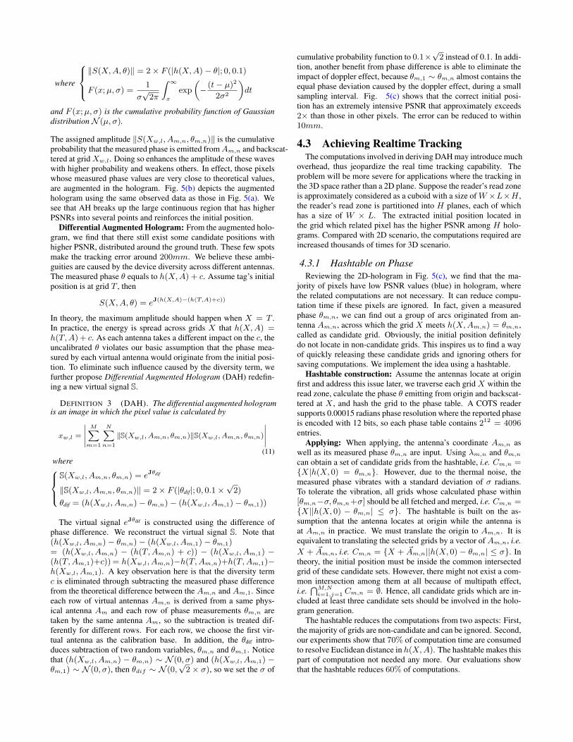
Figure 6: Modeling tag’s movement. Each antenna estimates atag’s radial velocity component along the direction between them.
4.3.2 Incremental Generation
It appears that the entire hologram is generated once enoughphase measurements are collected. Actually, the generation is anincremental process. The sum in Eqn. (12) can be decomposed intoa superimpose of M × N sub-holograms. Correspondingly, thecomputation can be decomposed into many time windows everytime a read is collected. Usually, the tag is interrogated about 30times per second so that the time window equals 0.03s, which islong enough to generate a sub-hologram. Therefore, our approachis able to guarantee the realtime object tracking at second level.
5. MOVEMENT WITH UNKNOWN TRACKIn this section, we relax the assumption that tag’s track function
is known in prior. Tagarom deals with the unpredictable movementwith the following two steps:
• Fitting tag’s trajectory: Tagoram acquires the phase mea-sured by M antennas from different directions to fit tag’strajectory every round of antenna scheduled.
• Selecting the optimal trajectory: Tagoram utilizes the DAHto evaluate all fitted trajectories and selects the optimal onecorresponding to the pixel with maximum PSNR.
Below we describe these two steps in detail.
5.1 Fitting Tag’s TrajectoryA tag can be interrogated for about 30 times per second in COTS
RFID system [12] while the most advanced automatic sorting sys-tem [15] supports a maximum conveyor velocity of 274.8mm/s.On average, the tag moves about 274.8 ∗ 1
30= 9.16mm, which is
far less than half a wavelength of available channel (≈ 160mm).This feature motivates us to estimate the tag’s radical speed throughthe phase difference of two adjacent reads. As illustrated in Fig. 6,the tag’s displacement ∆d during two adjacent reads θm,n andθm,n+1 for antenna Am can be approximated using Eq. (1):
∆d =
θm,n+1−θm,n
4π× λ, |θm,n − θm,n+1| < π
(2π−θm,n+θm,n+1)
4π× λ, θm,n − θm,n+1 ≥ π
θm,n+1−θm,n−2π
4π× λ, θm,n − θm,n+1 ≤ −π
(12)
Note that since above equation has taken a phase difference forgiven mth antenna, the antenna dependent diversity term has beennaturally eliminated. On the other hand, ∆d ≪ |f(tm,n) − Am|,then it is reasonable to approximate tag’s displacement along theradical direction i.e. Am → f(tm,n), equal to ∆d. Further, the
radical instant speed Vm,n can be estimated as follows:{Vm,n ≈ ∆d
tm,n+1−tm,n
∠Vm,n ≈ ∠(f(tn)−Am)(13)
∠X is the vector X’s direction, defined as the angle with x-axis.For completeness, we give an applicable upper band on the tag’sspeed, 160mm/0.033s = 484.9mm/s.
Speed chain: There are m real antennas monitoring the surveil-lance region, so we can estimate m instant radical speeds everyround of antenna schedule. The displacement between any two ad-jacent reads is so small that we simply model the tag’s movementduring a round as a uniform linear motion. The entire trajectorycan be well approximated by a piecewise linear curve. As shown
in Fig. 6, let ~Vn denote the tag’s real speed during the nth round,
and ~Vm,n be the radical speed measured by the mth antenna dur-
ing the nth round. Actually, ~Vm,n is the instant projection of ~Vn atdirection of Am → f(tm,n), namely:
|~Vm,n| = |~Vn| cos(∠~Vn − ∠~Vm,n) (14)
Above equation has two unknown parameters, the tag’s speed mag-
nitude |~Vn| and direction ∠~Vn. In theory, given two arbitrary es-timated radical speeds in different directions, both parameters canbe solved. Usually, a typical COTS RFID system supplies M ≥ 3antennas in practice, which yields
(M
2
)resolutions. So we adopt
fitting method to estimate the two parameters. The problem is for-malized as follows:
min |Vm,n − Vm,n|subject to: {(V1,n,∠V1,n), · · · , (VM,n,∠VM,n)}
(15)
We adopt the nonlinear least squares to estimate the tag’s instant
speed ~Vn in nth schedule, and use the GaussNewton method whichis based on a linear approximation of the objective function in theneighborhood of parameter vector. We start with an initial approxi-mation of the parameter vector and iteratively update this parametervector until it converges to a local minimum of an objective func-tion. When every round of antenna scheduling ends, a group ofmeasurements are obtained and the tag’s speed during this sched-ule can be fitted. Since we have N schedules for now, the output isactually a chain of tag’s speeds:
V = {~V1, · · · , ~VN}Trajectory function: We segment tag’s trajectory into a serials
of uniform linear movements in each round. The trajectory can beobtained using following recursive equation:
f(tn) = f(tn−1) + (tn − tn−1) · ~Vn = f(t0) +n∑
k=1
(tk − tk−1) · ~Vk (16)
where ~Vk ∈ V . As long as we know the initial position f(t0), thetag’s trajectory can be recursively inferred. Note that the optimizedmethod, such as Kalman filter [10], can be utilized to address themeasurement noise, which is not discussed in this paper due to thespace limit.
5.2 Selecting the Optimal TrajectoryAlthough the trajectory can be approximately calculated through
Eqn. (16), there still exists an unknown parameter f(t0), namelythe initial position. Given an arbitrate f(t0), either way Tagoramcan fit a trajectory. Choosing different grid as initial position mayresult in a different speed chain and further produce different tra-jectory. Which is the optimal one that most approaches the groundtruth? We leverage the DAH to answer this question. Being similarto track the initial position in §4, we assume f(t0) = Xw,l and fita trajectory fw,l. There are total W ×L candidate trajectories. Wesuperimpose all phase measurements along fw,l to fw,l(t0) as thesame process as tracking initial position using DAH. Our rational
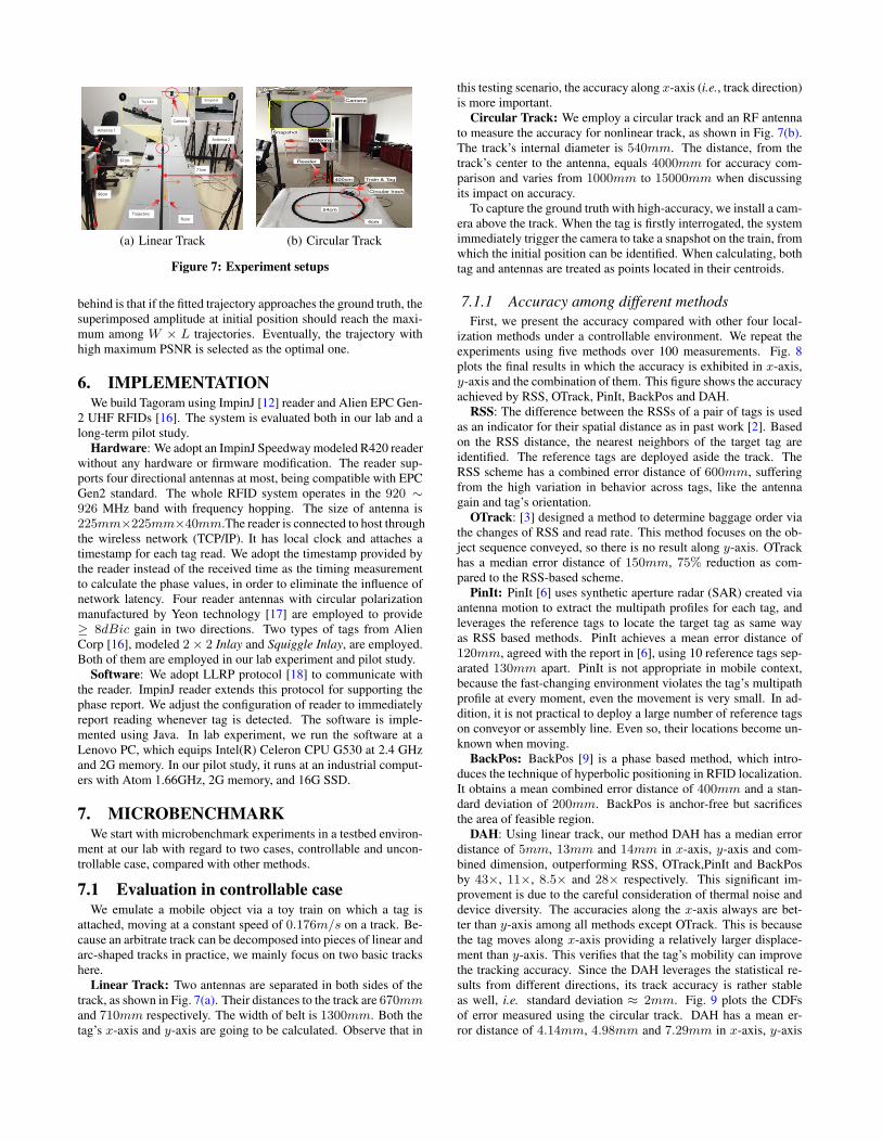
(a) Linear Track
Camera
Circular track
54cm
Reader
Antenna
400cm
4cm
Train & Tag
Snapshot
(b) Circular Track
Figure 7: Experiment setups
behind is that if the fitted trajectory approaches the ground truth, thesuperimposed amplitude at initial position should reach the maxi-mum among W × L trajectories. Eventually, the trajectory withhigh maximum PSNR is selected as the optimal one.
6. IMPLEMENTATIONWe build Tagoram using ImpinJ [12] reader and Alien EPC Gen-
2 UHF RFIDs [16]. The system is evaluated both in our lab and along-term pilot study.
Hardware: We adopt an ImpinJ Speedway modeled R420 readerwithout any hardware or firmware modification. The reader sup-ports four directional antennas at most, being compatible with EPCGen2 standard. The whole RFID system operates in the 920 ∼926 MHz band with frequency hopping. The size of antenna is225mm×225mm×40mm.The reader is connected to host throughthe wireless network (TCP/IP). It has local clock and attaches atimestamp for each tag read. We adopt the timestamp provided bythe reader instead of the received time as the timing measurementto calculate the phase values, in order to eliminate the influence ofnetwork latency. Four reader antennas with circular polarizationmanufactured by Yeon technology [17] are employed to provide≥ 8dBic gain in two directions. Two types of tags from AlienCorp [16], modeled 2× 2 Inlay and Squiggle Inlay, are employed.Both of them are employed in our lab experiment and pilot study.
Software: We adopt LLRP protocol [18] to communicate withthe reader. ImpinJ reader extends this protocol for supporting thephase report. We adjust the configuration of reader to immediatelyreport reading whenever tag is detected. The software is imple-mented using Java. In lab experiment, we run the software at aLenovo PC, which equips Intel(R) Celeron CPU G530 at 2.4 GHzand 2G memory. In our pilot study, it runs at an industrial comput-ers with Atom 1.66GHz, 2G memory, and 16G SSD.
7. MICROBENCHMARKWe start with microbenchmark experiments in a testbed environ-
ment at our lab with regard to two cases, controllable and uncon-trollable case, compared with other methods.
7.1 Evaluation in controllable caseWe emulate a mobile object via a toy train on which a tag is
attached, moving at a constant speed of 0.176m/s on a track. Be-cause an arbitrate track can be decomposed into pieces of linear andarc-shaped tracks in practice, we mainly focus on two basic trackshere.
Linear Track: Two antennas are separated in both sides of thetrack, as shown in Fig. 7(a). Their distances to the track are 670mmand 710mm respectively. The width of belt is 1300mm. Both thetag’s x-axis and y-axis are going to be calculated. Observe that in
this testing scenario, the accuracy along x-axis (i.e., track direction)is more important.
Circular Track: We employ a circular track and an RF antennato measure the accuracy for nonlinear track, as shown in Fig. 7(b).The track’s internal diameter is 540mm. The distance, from thetrack’s center to the antenna, equals 4000mm for accuracy com-parison and varies from 1000mm to 15000mm when discussingits impact on accuracy.
To capture the ground truth with high-accuracy, we install a cam-era above the track. When the tag is firstly interrogated, the systemimmediately trigger the camera to take a snapshot on the train, fromwhich the initial position can be identified. When calculating, bothtag and antennas are treated as points located in their centroids.
7.1.1 Accuracy among different methods
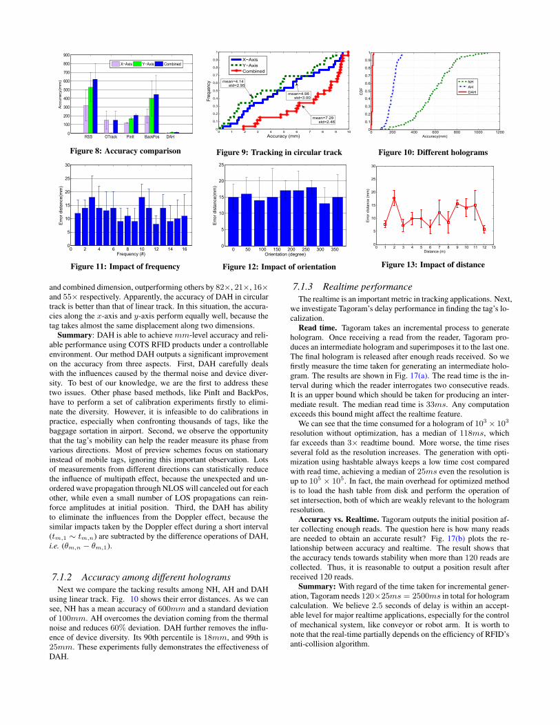
First, we present the accuracy compared with other four local-ization methods under a controllable environment. We repeat theexperiments using five methods over 100 measurements. Fig. 8plots the final results in which the accuracy is exhibited in x-axis,y-axis and the combination of them. This figure shows the accuracyachieved by RSS, OTrack, PinIt, BackPos and DAH.
RSS: The difference between the RSSs of a pair of tags is usedas an indicator for their spatial distance as in past work [2]. Basedon the RSS distance, the nearest neighbors of the target tag areidentified. The reference tags are deployed aside the track. TheRSS scheme has a combined error distance of 600mm, sufferingfrom the high variation in behavior across tags, like the antennagain and tag’s orientation.
OTrack: [3] designed a method to determine baggage order viathe changes of RSS and read rate. This method focuses on the ob-ject sequence conveyed, so there is no result along y-axis. OTrackhas a median error distance of 150mm, 75% reduction as com-pared to the RSS-based scheme.
PinIt: PinIt [6] uses synthetic aperture radar (SAR) created viaantenna motion to extract the multipath profiles for each tag, andleverages the reference tags to locate the target tag as same wayas RSS based methods. PinIt achieves a mean error distance of120mm, agreed with the report in [6], using 10 reference tags sep-arated 130mm apart. PinIt is not appropriate in mobile context,because the fast-changing environment violates the tag’s multipathprofile at every moment, even the movement is very small. In ad-dition, it is not practical to deploy a large number of reference tagson conveyor or assembly line. Even so, their locations become un-known when moving.
BackPos: BackPos [9] is a phase based method, which intro-duces the technique of hyperbolic positioning in RFID localization.It obtains a mean combined error distance of 400mm and a stan-dard deviation of 200mm. BackPos is anchor-free but sacrificesthe area of feasible region.
DAH: Using linear track, our method DAH has a median errordistance of 5mm, 13mm and 14mm in x-axis, y-axis and com-bined dimension, outperforming RSS, OTrack,PinIt and BackPosby 43×, 11×, 8.5× and 28× respectively. This significant im-provement is due to the careful consideration of thermal noise anddevice diversity. The accuracies along the x-axis always are bet-ter than y-axis among all methods except OTrack. This is becausethe tag moves along x-axis providing a relatively larger displace-ment than y-axis. This verifies that the tag’s mobility can improvethe tracking accuracy. Since the DAH leverages the statistical re-sults from different directions, its track accuracy is rather stableas well, i.e. standard deviation ≈ 2mm. Fig. 9 plots the CDFsof error measured using the circular track. DAH has a mean er-ror distance of 4.14mm, 4.98mm and 7.29mm in x-axis, y-axis
RSS OTrack PinIt BackPos DAH0
100
200
300
400
500
600
700
800
900A
ccura
cy(m
m)
X−Axis Y−Axis Combined
Figure 8: Accuracy comparison
0 1 2 3 4 5 6 7 8 9 100
0.1
0.2
0.3
0.4
0.5
0.6
0.7
0.8
0.9
1
Accuracy (mm)
Fre
quency
X−Axis
Y−Axis
Combined
mean=4.14 std=2.95
mean=4.98 std=3.00
mean=7.29 std=2.46
Figure 9: Tracking in circular track
0 200 400 600 800 1000 12000
0.1
0.2
0.3
0.4
0.5
0.6
0.7
0.8
0.9
1
Accuracy(mm)
CD
F
NH
AH
DAH
Figure 10: Different holograms
0 2 4 6 8 10 12 14 160
5
10
15
20
25
30
Frequency (#)
Err
or
dis
tance(m
m)
Figure 11: Impact of frequency
0 50 100 150 200 250 300 3500
5
10
15
20
25
Orientation (degree)
Err
or
dis
tance(m
m)
Figure 12: Impact of orientation
0 1 2 3 4 5 6 7 8 9 10 11 12 130
5
10
15
20
25
30
Distance (m)
Err
or
dis
tance (
mm
)
Figure 13: Impact of distance
and combined dimension, outperforming others by 82×, 21×, 16×and 55× respectively. Apparently, the accuracy of DAH in circulartrack is better than that of linear track. In this situation, the accura-cies along the x-axis and y-axis perform equally well, because thetag takes almost the same displacement along two dimensions.
Summary: DAH is able to achieve mm-level accuracy and reli-able performance using COTS RFID products under a controllableenvironment. Our method DAH outputs a significant improvementon the accuracy from three aspects. First, DAH carefully dealswith the influences caused by the thermal noise and device diver-sity. To best of our knowledge, we are the first to address thesetwo issues. Other phase based methods, like PinIt and BackPos,have to perform a set of calibration experiments firstly to elimi-nate the diversity. However, it is infeasible to do calibrations inpractice, especially when confronting thousands of tags, like thebaggage sortation in airport. Second, we observe the opportunitythat the tag’s mobility can help the reader measure its phase fromvarious directions. Most of preview schemes focus on stationaryinstead of mobile tags, ignoring this important observation. Lotsof measurements from different directions can statistically reducethe influence of multipath effect, because the unexpected and un-ordered wave propagation through NLOS will canceled out for eachother, while even a small number of LOS propagations can rein-force amplitudes at initial position. Third, the DAH has abilityto eliminate the influences from the Doppler effect, because thesimilar impacts taken by the Doppler effect during a short interval(tm,1 ∼ tm,n) are subtracted by the difference operations of DAH,i.e. (θm,n − θm,1).
7.1.2 Accuracy among different holograms
Next we compare the tacking results among NH, AH and DAHusing linear track. Fig. 10 shows their error distances. As we cansee, NH has a mean accuracy of 600mm and a standard deviationof 100mm. AH overcomes the deviation coming from the thermalnoise and reduces 60% deviation. DAH further removes the influ-ence of device diversity. Its 90th percentile is 18mm, and 99th is25mm. These experiments fully demonstrates the effectiveness ofDAH.
7.1.3 Realtime performance
The realtime is an important metric in tracking applications. Next,we investigate Tagoram’s delay performance in finding the tag’s lo-calization.
Read time. Tagoram takes an incremental process to generatehologram. Once receiving a read from the reader, Tagoram pro-duces an intermediate hologram and superimposes it to the last one.The final hologram is released after enough reads received. So wefirstly measure the time taken for generating an intermediate holo-gram. The results are shown in Fig. 17(a). The read time is the in-terval during which the reader interrogates two consecutive reads.It is an upper bound which should be taken for producing an inter-mediate result. The median read time is 33ms. Any computationexceeds this bound might affect the realtime feature.
We can see that the time consumed for a hologram of 103 × 103
resolution without optimization, has a median of 118ms, whichfar exceeds than 3× readtime bound. More worse, the time risesseveral fold as the resolution increases. The generation with opti-mization using hashtable always keeps a low time cost comparedwith read time, achieving a median of 25ms even the resolution isup to 105 × 105. In fact, the main overhead for optimized methodis to load the hash table from disk and perform the operation ofset intersection, both of which are weakly relevant to the hologramresolution.
Accuracy vs. Realtime. Tagoram outputs the initial position af-ter collecting enough reads. The question here is how many readsare needed to obtain an accurate result? Fig. 17(b) plots the re-lationship between accuracy and realtime. The result shows thatthe accuracy tends towards stability when more than 120 reads arecollected. Thus, it is reasonable to output a position result afterreceived 120 reads.
Summary: With regard of the time taken for incremental gener-ation, Tagoram needs 120×25ms = 2500ms in total for hologramcalculation. We believe 2.5 seconds of delay is within an accept-able level for major realtime applications, especially for the controlof mechanical system, like conveyor or robot arm. It is worth tonote that the real-time partially depends on the efficiency of RFID’santi-collision algorithm.
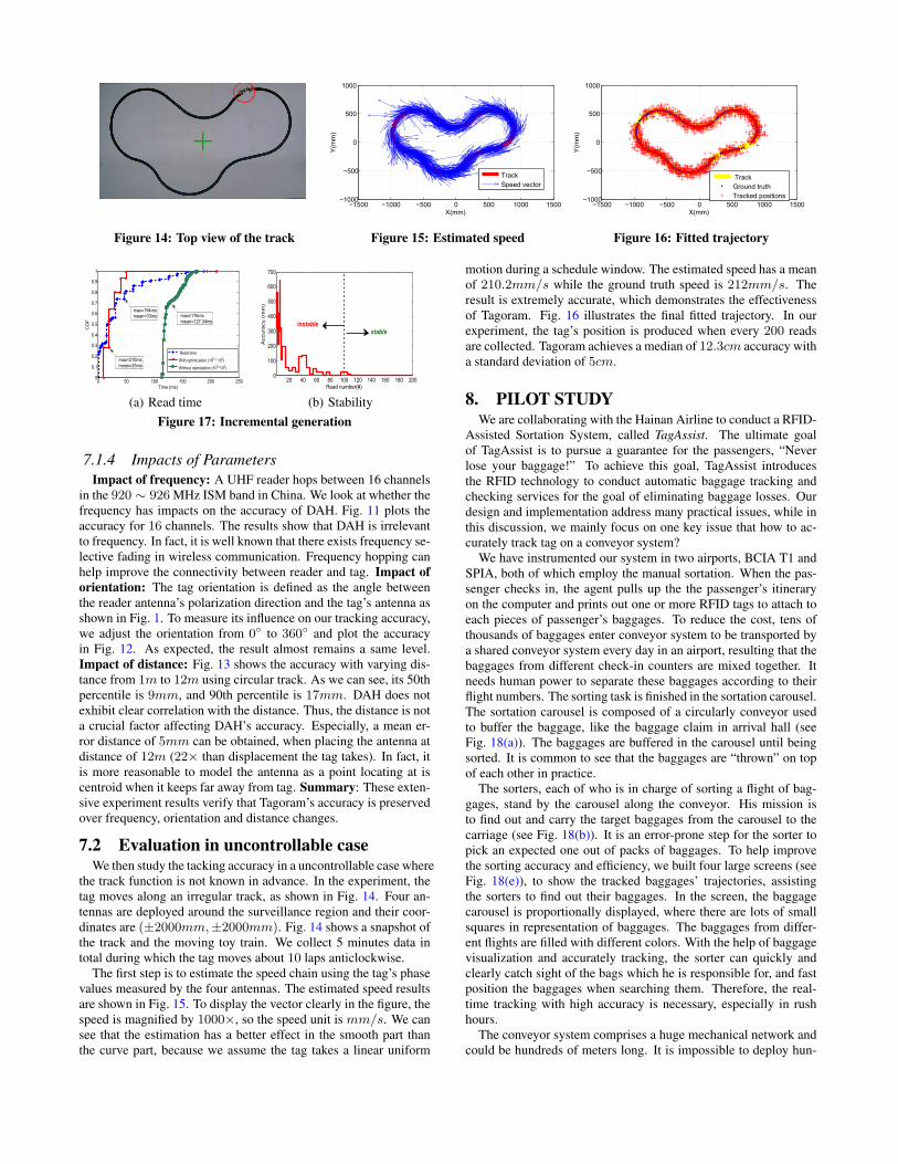
Figure 14: Top view of the track
−1500 −1000 −500 0 500 1000 1500−1000
−500
0
500
1000
X(mm)
Y(m
m)
Track
Speed vector
Figure 15: Estimated speed
−1500 −1000 −500 0 500 1000 1500−1000
−500
0
500
1000
X(mm)
Y(m
m)
Track
Ground truth
Tracked positions
Figure 16: Fitted trajectory
0 50 100 150 200 2500
0.1
0.2
0.3
0.4
0.5
0.6
0.7
0.8
0.9
1
Time (ms)
CD
F
Read time
With optimization (105 * 10
5)
Without opimization (102*10
2)
max=210ms mean=25ms
max=194ms mean=33ms max=176ms
mean=127.34ms
(a) Read time
20 40 60 80 100 120 140 160 180 2000
100
200
300
400
500
600
700
Read number(#)
Accura
cy (
mm
)
instable
stable
(b) Stability
Figure 17: Incremental generation
7.1.4 Impacts of Parameters
Impact of frequency: A UHF reader hops between 16 channelsin the 920 ∼ 926 MHz ISM band in China. We look at whether thefrequency has impacts on the accuracy of DAH. Fig. 11 plots theaccuracy for 16 channels. The results show that DAH is irrelevantto frequency. In fact, it is well known that there exists frequency se-lective fading in wireless communication. Frequency hopping canhelp improve the connectivity between reader and tag. Impact of
orientation: The tag orientation is defined as the angle betweenthe reader antenna’s polarization direction and the tag’s antenna asshown in Fig. 1. To measure its influence on our tracking accuracy,we adjust the orientation from 0◦ to 360◦ and plot the accuracyin Fig. 12. As expected, the result almost remains a same level.Impact of distance: Fig. 13 shows the accuracy with varying dis-tance from 1m to 12m using circular track. As we can see, its 50thpercentile is 9mm, and 90th percentile is 17mm. DAH does notexhibit clear correlation with the distance. Thus, the distance is nota crucial factor affecting DAH’s accuracy. Especially, a mean er-ror distance of 5mm can be obtained, when placing the antenna atdistance of 12m (22× than displacement the tag takes). In fact, itis more reasonable to model the antenna as a point locating at iscentroid when it keeps far away from tag. Summary: These exten-sive experiment results verify that Tagoram’s accuracy is preservedover frequency, orientation and distance changes.
7.2 Evaluation in uncontrollable caseWe then study the tacking accuracy in a uncontrollable case where
the track function is not known in advance. In the experiment, thetag moves along an irregular track, as shown in Fig. 14. Four an-tennas are deployed around the surveillance region and their coor-dinates are (±2000mm,±2000mm). Fig. 14 shows a snapshot ofthe track and the moving toy train. We collect 5 minutes data intotal during which the tag moves about 10 laps anticlockwise.
The first step is to estimate the speed chain using the tag’s phasevalues measured by the four antennas. The estimated speed resultsare shown in Fig. 15. To display the vector clearly in the figure, thespeed is magnified by 1000×, so the speed unit is mm/s. We cansee that the estimation has a better effect in the smooth part thanthe curve part, because we assume the tag takes a linear uniform
motion during a schedule window. The estimated speed has a meanof 210.2mm/s while the ground truth speed is 212mm/s. Theresult is extremely accurate, which demonstrates the effectivenessof Tagoram. Fig. 16 illustrates the final fitted trajectory. In ourexperiment, the tag’s position is produced when every 200 readsare collected. Tagoram achieves a median of 12.3cm accuracy witha standard deviation of 5cm.
8. PILOT STUDYWe are collaborating with the Hainan Airline to conduct a RFID-
Assisted Sortation System, called TagAssist. The ultimate goalof TagAssist is to pursue a guarantee for the passengers, “Neverlose your baggage!” To achieve this goal, TagAssist introducesthe RFID technology to conduct automatic baggage tracking andchecking services for the goal of eliminating baggage losses. Ourdesign and implementation address many practical issues, while inthis discussion, we mainly focus on one key issue that how to ac-curately track tag on a conveyor system?
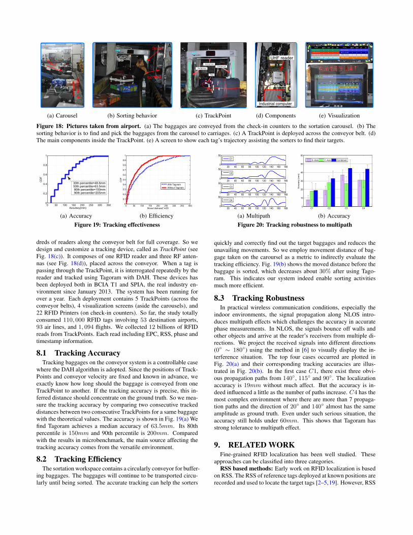
We have instrumented our system in two airports, BCIA T1 andSPIA, both of which employ the manual sortation. When the pas-senger checks in, the agent pulls up the the passenger’s itineraryon the computer and prints out one or more RFID tags to attach toeach pieces of passenger’s baggages. To reduce the cost, tens ofthousands of baggages enter conveyor system to be transported bya shared conveyor system every day in an airport, resulting that thebaggages from different check-in counters are mixed together. Itneeds human power to separate these baggages according to theirflight numbers. The sorting task is finished in the sortation carousel.The sortation carousel is composed of a circularly conveyor usedto buffer the baggage, like the baggage claim in arrival hall (seeFig. 18(a)). The baggages are buffered in the carousel until beingsorted. It is common to see that the baggages are “thrown” on topof each other in practice.
The sorters, each of who is in charge of sorting a flight of bag-gages, stand by the carousel along the conveyor. His mission isto find out and carry the target baggages from the carousel to thecarriage (see Fig. 18(b)). It is an error-prone step for the sorter topick an expected one out of packs of baggages. To help improvethe sorting accuracy and efficiency, we built four large screens (seeFig. 18(e)), to show the tracked baggages’ trajectories, assistingthe sorters to find out their baggages. In the screen, the baggagecarousel is proportionally displayed, where there are lots of smallsquares in representation of baggages. The baggages from differ-ent flights are filled with different colors. With the help of baggagevisualization and accurately tracking, the sorter can quickly andclearly catch sight of the bags which he is responsible for, and fastposition the baggages when searching them. Therefore, the real-time tracking with high accuracy is necessary, especially in rushhours.
The conveyor system comprises a huge mechanical network andcould be hundreds of meters long. It is impossible to deploy hun-
Input
Movemnet
(a) Carousel
Sorter
Sorting
(b) Sorting behavior (c) TrackPoint
UHF reader
Industrial computer
(d) Components (e) Visualization
Figure 18: Pictures taken from airport. (a) The baggages are conveyed from the check-in counters to the sortation carousel. (b) Thesorting behavior is to find and pick the baggages from the carousel to carriages. (c) A TrackPoint is deployed across the conveyor belt. (d)The main components inside the TrackPoint. (e) A screen to show each tag’s trajectory assisting the sorters to find their targets.
0 50 100 150 200 250 300 3500
0.2
0.4
0.6
0.8
1
Accuracy(mm)
CD
F
30th percentile=48.6mm 50th percentile=63.5mm 80th percentile=150mm 90th percentile=205mm
(a) Accuracy
0 50 100 150 200 250 300 350 4000
0.1
0.2
0.3
0.4
0.5
0.6
0.7
0.8
0.9
1
Moved distnace£¨m£©
CD
F
With Tagoram
Without Tagoram
(b) Efficiency
Figure 19: Tracking effectiveness
dreds of readers along the conveyor belt for full coverage. So wedesign and customize a tracking device, called as TrackPoint (seeFig. 18(c)). It composes of one RFID reader and three RF anten-nas (see Fig. 18(d)), placed across the conveyor. When a tag ispassing through the TrackPoint, it is interrogated repeatedly by thereader and tracked using Tagoram with DAH. These devices hasbeen deployed both in BCIA T1 and SPIA, the real industry en-vironment since January 2013. The system has been running forover a year. Each deployment contains 5 TrackPoints (across theconveyor belts), 4 visualization screens (aside the carousels), and22 RFID Printers (on check-in counters). So far, the study totallyconsumed 110, 000 RFID tags involving 53 destination airports,93 air lines, and 1, 094 flights. We collected 12 billions of RFIDreads from TrackPoints. Each read including EPC, RSS, phase andtimestamp information.
8.1 Tracking AccuracyTracking baggages on the conveyor system is a controllable case
where the DAH algorithm is adopted. Since the positions of Track-Points and conveyor velocity are fixed and known in advance, weexactly know how long should the baggage is conveyed from oneTrackPoint to another. If the tracking accuracy is precise, this in-ferred distance should concentrate on the ground truth. So we mea-sure the tracking accuracy by comparing two consecutive trackeddistances between two consecutive TrackPoints for a same baggagewith the theoretical values. The accuracy is shown in Fig. 19(a) Wefind Tagoram achieves a median accuracy of 63.5mm. Its 80thpercentile is 150mm and 90th percentile is 200mm. Comparedwith the results in microbenchmark, the main source affecting thetracking accuracy comes from the versatile environment.
8.2 Tracking EfficiencyThe sortation workspace contains a circularly conveyor for buffer-
ing baggages. The baggages will continue to be transported circu-larly until being sorted. The accurate tracking can help the sorters
20 40 60 80 100 120 140 160 1800
50
C1
20 40 60 80 100 120 140 160 1800
50
C2
20 40 60 80 100 120 140 160 1800
50
C3
20 40 60 80 100 120 140 160 1800
50
C4
(a) Multipath
C1 C2 C3 C40
10
20
30
40
50
60
Accura
cy (
mm
)
X−Axis Y−Axis Combined
(b) Accuracy
Figure 20: Tracking robustness to multipath
quickly and correctly find out the target baggages and reduces theunavailing movements. So we employ movement distance of bag-gage taken on the caroursel as a metric to indirectly evaluate thetracking efficiency. Fig. 19(b) shows the moved distance before thebaggage is sorted, which decreases about 30% after using Tago-ram. This indicates our system indeed enable sorting activitiesmuch more efficient.
8.3 Tracking RobustnessIn practical wireless communication conditions, especially the
indoor environments, the signal propagation along NLOS intro-duces multipath effects which challenges the accuracy in accuratephase measurements. In NLOS, the signals bounce off walls andother objects and arrive at the reader’s receivers from multiple di-rections. We project the received signals into different directions(0◦ ∼ 180◦) using the method in [6] to visually display the in-terference situation. The top four cases occurred are plotted inFig. 20(a) and their corresponding tracking accuracies are illus-trated in Fig. 20(b). In the first case C1, there exist three obvi-ous propagation paths from 140◦, 115◦ and 90◦. The localizationaccuracy is 19mm without much affect. But the accuracy is in-deed influenced a little as the number of paths increase. C4 has themost complex environment where there are more than 7 propaga-tion paths and the direction of 20◦ and 140◦ almost has the sameamplitude as ground truth. Even under such serious situation, theaccuracy still holds under 60mm. This shows that Tagoram hasstrong tolerance to multipath effect.
9. RELATED WORKFine-grained RFID localization has been well studied. These
approaches can be classified into three categories.RSS based methods: Early work on RFID localization is based
on RSS. The RSS of reference tags deployed at known positions arerecorded and used to locate the target tags [2–5,19]. However, RSS
is not a reliable location indicator, especially for UHF tags, whichis highly relevant to the tag’s orientation and antenna gain [4]. Inmobile environment, the orientation cannot be known.
Phase based methods: There is a growing interest in usingphase information to locate tags. These methods can be dividedinto two categories, AoA (Angle of Arrival) and SAR (syntheticaperture). AoA locates the tag by measuring the phase differencebetween the received signals at different antennas, [5, 7, 8]. Themajor challenges for these methods are to deal with NLOS. SARmethods are firstly used in Radar system for both object localiza-tion and terrain imaging with help of antenna array [1, 6, 20, 21].PinIt [6] employs a moved antenna to measure the multipath pro-files of reference tags at known positions and locates the target tag.The technique of PinIt is further applied in robot object manipula-tion [1]. The merit of PinIt is able to locate tag in NLOS environ-ment. However, it needs to deploy dense reference tags in advance.Miesen et al. [20] also employ the moving antenna to constructSAR and find out tag’s location with naive hologram. Parr [21] ex-tends the technique proposed in [20] in mobile context to determinewhether a tag moves along a supposed trajectory. While Tagoramemploys tag’s mobility to generate Inverse SAR-style antenna ar-ray, it significantly differs from previous work in that it focuses ontracking mobile tag in mm-level while dealing with both thermalnoise and device diversity. Besides, Tagoram is able to track themobile tag under uncontrollable case in which the trajectory func-tion is unknown.
Proximity based methods: The last type of localization tech-nique is based on proximity [22–27]. This approach relies on densedeployment of antenna. When the target tag enters in the radiorange of an antenna, its location is assumed to be the same as thisreceiver. Liu et al. present a new communication system that en-ables two battery-free devices to communicate using ambient RFas the only source of power. which might open a new trackingtechnique among tags within few centimeter [25].
10. CONCLUSIONIn this work we present Tagoram for real-time tracking of mobile
RFID tags using Commercial Off-The-Shelf (COTS) RFID tagsand readers, to a high precision ( cm- and mm-level). A key in-novation is to build a differential augmented hologram using thephase values collected from physical antennas, and to leverage thetag mobility to construct a virtual antenna array. Tagoram can pin-point the tag position to an accuracy of a few centimeter, providingthe necessary precision for many novel applications, such as ob-ject grasping by robot. The system Tagoram not only has beentested and used in practical applications, but also will open up awide range of exciting opportunities due to its instant tracking andextremely high accuracy.
11. ACKNOWLEDGMENTThis research is partially supported by NSFC under Grant No.
61190110 and NSFC CERG-61361166009. The research of Xiang-Yang Li is partially supported by NSF CNS-1035894, NSF ECCS-1247944, NSF ECCS-1343306, National Natural Science Founda-tion of China under Grants No. 61170216, No. 61228202. Theresearch of Mo Li is supported from Singapore MOE AcRF Tier 1grant RG17/13, and Nanyang Assistant Professorship (NAP) grantM4080738.020 of NTU. We thank all the reviewers and shepherdsfor their valuable comments and helpful suggestions.
12. REFERENCES
[1] J. Wang, F. Adib, R. Knepper, D. Katabi, and D. Rus, “Rf-compass:robot object manipulation using rfids,” in Proc. of ACM MobiCom,2013.
[2] L. Ni, Y. Liu, Y. Lau, and A. Patil, “Landmarc: Indoor locationsensing using active rfid,” Wireless networks, 2004.
[3] L. Shangguan, Z. Li, Z. Yang, M. Li, and Y. Liu, “Otrack: Ordertracking for luggage in mobile rfid systems,” in Proc. of IEEE
INFOCOM, 2013.
[4] J. D. Griffin and G. D. Durgin, “Complete link budgets forbackscatter-radio and rfid systems,” IEEE Antennas and Propagation
Magazine, vol. 51, no. 2, pp. 11–25, 2009.
[5] C. Hekimian-Williams, B. Grant, X. Liu, Z. Zhang, and P. Kumar,“Accurate localization of rfid tags using phase difference,” in Proc. of
IEEE RFID, 2010.
[6] J. Wang and D. Katabi, “Dude, where’s my card?: Rfid positioningthat works with multipath and non-line of sight,” in Proc. of ACM
SIGCOMM, 2013.
[7] S. Azzouzi, M. Cremer, U. Dettmar, R. Kronberger, and T. Knie,“New measurement results for the localization of uhf rfidtransponders using an angle of arrival (aoa) approach,” in Proc. of
IEEE RFID, 2011.
[8] P. V. Nikitin, R. Martinez, S. Ramamurthy, H. Leland, G. Spiess, andK. Rao, “Phase based spatial identification of uhf rfid tags,” in Proc.
of IEEE RFID, 2010.
[9] T. Liu, L. Yang, Q. Lin, Y. Guo, and Y. Liu, “Anchor-free backscatterpositioning for rfid tagswith high accuracy,” in Proc. of IEEE
INFOCOM, 2014.
[10] S. Sarkka, V. V. Viikari, M. Huusko, and K. Jaakkola, “Phase-baseduhf rfid tracking with nonlinear kalman filtering and smoothing,”IEEE Sensors Journal, vol. 12, no. 5, pp. 904–910, 2012.
[11] ImpinJ, “Speedway revolution reader application note: Low leveluser data support,” in Speedway Revolution Reader Application Note,2010.
[12] “Impinj, Inc,” http://www.impinj.com/.
[13] P. Zhang, J. Gummeson, and D. Ganesan, “Blink: A high throughputlink layer for backscatter communication,” in Proc. of ACM MobiSys,2012.
[14] L. Yang, J. Han, Y. Qi, C. Wang, T. Gu, and Y. Liu, “Season:Shelving interference and joint identification in large-scale rfidsystems,” in Proc. of IEEE INFOCOM, 2011.
[15] “Dematic,” http://www.dematic.com/linear-sorters.
[16] “Alien,” http://www.alientechnology.com/tags.
[17] “Yeon,” http://www.yeon.com.tw/.
[18] EPCglobal, “Low level reader protocol (llrp),” 2010.
[19] G. Li, D. Arnitz, R. Ebelt, U. Muehlmann, K. Witrisal, andM. Vossiek, “Bandwidth dependence of cw ranging to uhf rfid tags insevere multipath environments,” in Proc. of IEEE RFID.
[20] R. Miesen, F. Kirsch, and M. Vossiek, “Holographic localization ofpassive uhf rfid transponders,” in Proc. of IEEE RFID, 2011.
[21] A. Parr, R. Miesen, and M. Vossiek, “Inverse sar approach forlocalization of moving rfid tags,” in Proc. of IEEE RFID, 2013.
[22] W. Zhu, J. Cao, Y. Xu, L. Yang, and J. Kong, “Fault-tolerant rfidreader localization based on passive rfid tags,” in Proc. of IEEE
INFOCOM, 2012.
[23] Y. Liu, L. Chen, J. Pei, Q. Chen, and Y. Zhao, “Mining frequenttrajectory patterns for activity monitoring using radio frequency tagarrays,” in Proc. of IEEE PerCom, 2007.
[24] Y. Guo, L. Yang, B. Li, T. Liu, and Y. Liu, “Rollcaller: User-friendlyindoor navigation system using human-item spatial relation,” 2014.
[25] V. Liu, A. Parks, V. Talla, S. Gollakota, D. Wetherall, and J. R.Smith, “Ambient backscatter: Wireless communication out of thinair,” in Proc. of ACM SIGCOMM, 2013.
[26] Y. Zheng and M. Li, “P-mti: Physical-layer missing tag identificationvia compressive sensing,” in Proc. of IEEE INFOCOM, 2013.
[27] L. Yang, Y. Qi, J. Fang, and et al., “Frogeye: Perception of theslightest tag motion,” in Proc. of IEEE INFOCOM, 2014.