table of contents - allan blockect installation checklist, project inspection checklist, reference...
TRANSCRIPT
Inside this issue:Product Standards ...............................................2
Installation Specifications .....................................4
Water Management .............................................6
ASTM Standards .................................................8
Design, Construction and Inspection Check Lists .........................................10
Design Details .................................................... 12
Water ManagementDetails ............................................................... 13
Geogrid Details ................................................... 14
Fencing Applications ........................................... 15
Miscellaneous Details ......................................... 16
Design Methods ................................................. 18
Allowable ConstructionTolerances ......................................................... 19
Reinforcement Specifications ............................... 21
Table of Contents
allanblock.com
List of Tables:Table 1: Embankment Protection
Fabric Specifications .......................... 7
Table 2: Strength and Absorption Requirements (ASTM) ....................... 8
Table 3: Geogrid Manufacturers Testing Results ................................... 22
The most current, up-to-date information canbe found on our website at allanblock.com.
Also see Best Practices forSRW Design for moredetailed information.
List of Figures:Fig 1: Geogrid Wall Consolidation Zone ................5
Fig 2: Surface Water Management ...................... 6
Fig 3: Construction Water Management .............. 6
Fig 4A: Internal Blanket ....................................... 7
Fig 4B: Internal Blanket and Chimney Drain ........... 7
Fig 5: Freeze-Thaw Testing ............................... 9
Fig 6: Global Stability ....................................... 10
Fig 7: Elevation View ........................................ 10
Fig 8: Wall Site Components .............................. 10
Fig 9: Typical Reinforcement Configurations ........................................ 11
Fig 10: Wall Design Envelope .............................. 11
Fig 11: Vertical Control .......................................19
Fig 12: Differential Settlements ............................ 19
Fig 13: Horizontal Control ....................................19
Fig 14: Rotation ................................................. 19
allanblock.com
Allan Block Corporation:
A leader in segmental retaining wall design
The following pages will provide assistance to a broadrange of professional retaining wall designers. Thistechnical specification manual will allow a wall design-er to source and reference specific information for usein developing project documents. Included are: prod-uct standards, installation and water management pro-cedures, design details, industry standards, allowableconstruction tolerances, project design checklist, proj-ect installation checklist, project inspection checklist,reference design methods, and geogrid reinforcementoptions.
The goal is to provide formatted specification sheetsthat summarize information published by Allan Blockand other relevant publications, as well as provide acomprehensive document for most applications whichutilize mortarless concrete block as a component of asegmental retaining wall.
The document focuses on composite structures builtby combining an Allan Block facing unit with a rein-forced soil mass, and appropriate drainage details.Other methods of reinforcement will be illustrated in
Answering the question:Can segmental retaining walls satisfy the requirements of my project?
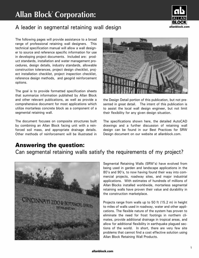
Segmental Retaining Walls (SRW’s) have evolved frombeing used in garden and landscape applications in the80’s and 90’s, to now having found their way into com-mercial projects, roadway sites, and major industrialapplications. With estimates of hundreds of millions ofAllan Blocks installed worldwide, mortarless segmentalretaining walls have proven their value and durability inthe construction marketplace.
Projects range from walls up to 50 ft (15.2 m) in heightto miles of walls used in roadway, water and other appli-cations. The flexible nature of the system has proven toeliminate the need for frost footings in northern cli-mates, provide additional drainage in tropical areas, andallow for additional flexibility in earthquake plagued sec-tions of the world. In short, there are very few siteproblems that cannot find a cost effective solution usingAllan Block Retaining Wall Products.
1
the Design Detail portion of this publication, but not pre-sented in great detail. The intent of this publication isto assist the local wall design engineer, but not limittheir flexibility for any given design situation.
The specifications shown here, the detailed AutoCADdrawings and a further discussion of retaining walldesign can be found in our Best Practices for SRWDesign document on our website at allanblock.com.
allanblock.com
®

cern in northern tier states or countries that use deicing salts. Based on good performance experience by several agencies, ASTM C1372, or equivalent governing standard or public authority, Standard Specification for Segmental Retaining Wall Units should be used as a model, except that the compressive strength for the units should be increased to a minimum of 4,000 – 5,800 psi (28 - 40 MPa) unless local requirements dic-tate higher levels. Also, maximum water absorption should be reduced and requirements for freeze-thaw testing increased.
a. Require a current passing ASTM C1262 or equivalent governing standard or public authority, test report from material supplier in northern or cold weather climates.
b. See the Best Practices for SRW Design document for detailed information on freeze thaw durability testing cri-teria and regional temperature and exposure severity fig-ures and tables to define the appropriate zone and requirements for the project.
2.2 Wall Rock A. Material must be well-graded compactible aggregate, 0.25 in.
to 1.5 in., (6 mm - 38 mm) with no more than 10% passing the #200 sieve. (ASTM D422)
B. Material behind and within the blocks may be the same material. 2.3 Infill Soil A. Infill material shall be site excavated soils when approved by
the on-site soils engineer unless otherwise specified in the drawings. Unsuitable soils for backfill (heavy clays or organic soils) shall not be used in the reinforced soil mass. Fine grained cohesive soils with friction angle (Ñ) less than 31 degrees with a PI ranging between 6 and 20 and LL from 30 to 40, may be used in wall construction, but additional back-filling, compaction and water management efforts are required. Poorly graded sands, expansive clays and/or soils with a plasticity index (PI) greater than 20 or a liquid limit (LL) greater than 40 should not be used in wall construction.
B. The infill soil used must meet or exceed the designed friction angle and description noted on the design cross sections, and must be free of debris and consist of one of the following inorganic USCS soil types: GP, GW, SW, SP, GP-GM or SP-SM meeting the following gradation as determined in accordance with ASTM D422.
C. Where additional fill is required, contractor shall submit sample and specifications to the wall design engineer or the on-site soils engineer for approval and the approving engineer must certify that the soils proposed for use has properties meeting or exceeding original design standards.
PART 3: WALL CONSTRUCTION 3.1 Excavation A. Contractor shall excavate to the lines and grades shown on
the construction drawings. Contractor shall use caution not to over-excavate beyond the lines shown, or to disturb the base elevations beyond those shown.
B. Contractor shall verify locations of existing structures and utili-ties prior to excavation. Contractor shall ensure all surrounding structures are protected from the effects of wall excavation.
3.2 Foundation Soil Preparation A. Foundation soil shall be defined as any soils located beneath a wall. B. Foundation soil shall be excavated as dimensioned on the plans
and compacted to a minimum of 95% of Standard Proctor (ASTM D698) prior to placement of the base material.
2
Allan Block Product Standards
Sieve Size % Passing1 in (25 mm) 100 - 75
No. 4 (4.75 mm) 100 - 20No. 40 (0.425 mm) 0 - 60No. 200 (0.075 mm) 0 - 35
Specification Guidelines: Allan Block Modular Retaining Wall Systems The following specifications provide Allan Block Corporation's typical requirements and recommendations. At the engineer of record's discretion these specifications may be revised to accommodate site specific design requirements.
SECTION 1 PART 1: GENERAL 1.1 Scope Work includes furnishing and installing modular concrete block
retaining wall units to the lines and grades designated on the con-struction drawings and as specified herein.
1.2 Applicable Sections of Related Work Geogrid Wall Reinforcement (see Section 2, Page 4) 1.3 Reference Standards A. ASTM C1372 Standard Specification for Segmental
Retaining Wall Units. B. ASTM C1262 Evaluating the Freeze Thaw Durability of
Manufactured CMU’s and Related Concrete Units C. ASTM D698 Moisture Density Relationship for Soils,
Standard Method D. ASTM D422 Gradation of Soils E. ASTM C140 Sample and Testing Concrete Masonry Units
1.4 Delivery, Storage, and Handling A. Contractor shall check the materials upon delivery to assure proper
material has been received. B. Contractor shall prevent excessive mud, cementitious material, and
like construction debris from coming in contact with the materials. C. Contractor shall protect the materials from damage. Damaged
material shall not be incorporated in the project (ASTM C1372).
1.5 Contractor Requirements Contractors shall be trained and certified by local manufacturer or equivalent accredited organization. A. Allan Block and NCMA have certification programs that are accred-
ited. Identify when advanced certification levels are appropriate based on complexity and criticality of project application.
B. Contractors shall provide a list of projects they have completed.
PART 2: MATERIALS 2.1 Modular Wall Units A. Wall units shall be Allan Block Retaining Wall units as produced
by a licensed manufacturer. B. Wall units shall have minimum 28 day compressive strength of
3000 psi (20.7 MPa) in accordance with ASTM C1372. The concrete units shall have adequate freeze-thaw protection with an average absorption rate in accordance with ASTM C1372 or an average absorption rate of 7.5 lb/ft3 (120 kg/m3) for northern climates and 10 lb/ft3 (160 kg/m3) for southern climates.
C. Exterior dimensions shall be uniform and consistent. Maximum dimensional deviations on the height of any two units shall be 0.125 in. (3 mm).
D. Wall units shall provide a minimum of 110 lbs total weight per square foot of wall face area (555 kg/m²). Hollow cores to be filled with wall rock and compacted by using plate compactor on top of wall units (see section 3.4). Unit weight of wall rock in cores may be less than 100% depending on compaction levels.
E. Exterior face shall be textured. Color as specified by owner. F. Freeze Thaw Durability: Like all concrete products, dry-cast con-
crete SRW units are susceptible to freeze-thaw degradation with exposure to de-icing salts and cold temperature. This is a con-
allanblock.com
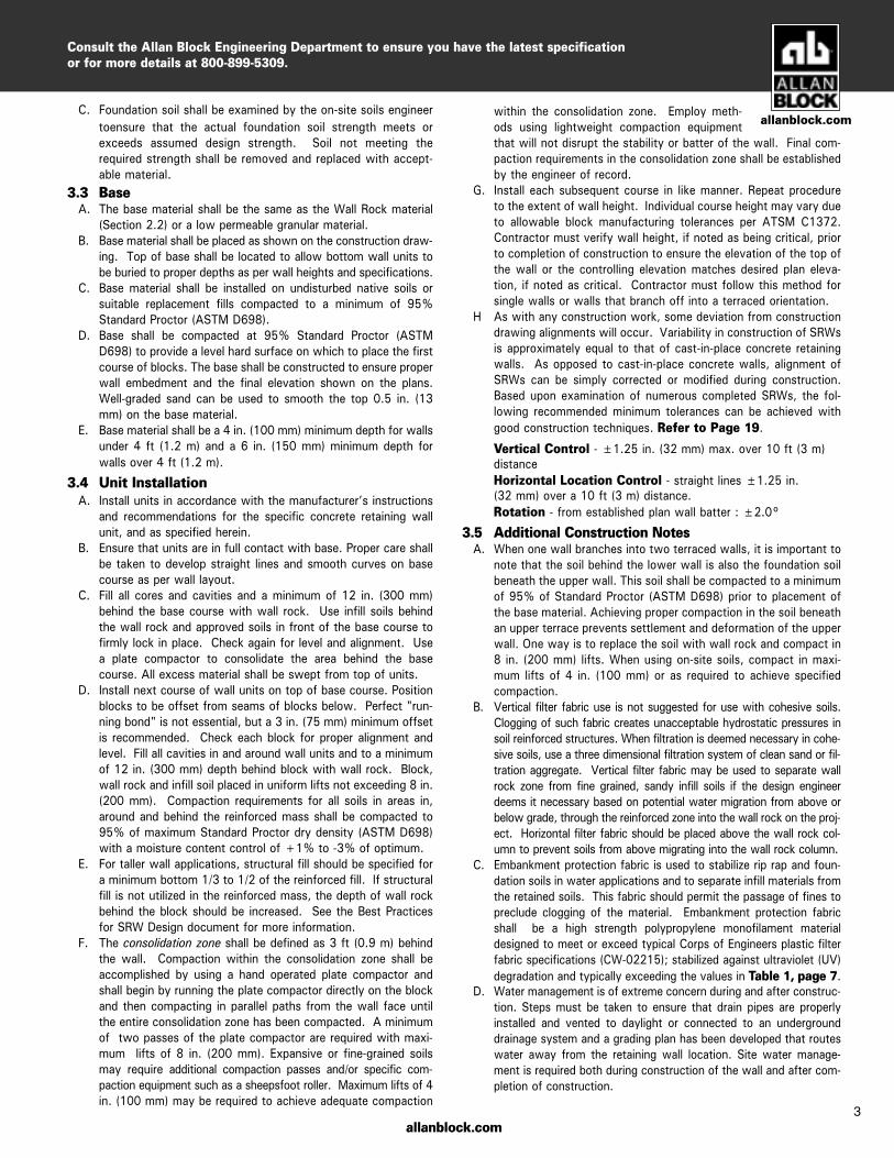
C. Foundation soil shall be examined by the on-site soils engineer toensure that the actual foundation soil strength meets or exceeds assumed design strength. Soil not meeting the required strength shall be removed and replaced with accept-able material.
3.3 Base A. The base material shall be the same as the Wall Rock material
(Section 2.2) or a low permeable granular material. B. Base material shall be placed as shown on the construction draw-
ing. Top of base shall be located to allow bottom wall units to be buried to proper depths as per wall heights and specifications.
C. Base material shall be installed on undisturbed native soils or suitable replacement fills compacted to a minimum of 95% Standard Proctor (ASTM D698).
D. Base shall be compacted at 95% Standard Proctor (ASTM D698) to provide a level hard surface on which to place the first course of blocks. The base shall be constructed to ensure proper wall embedment and the final elevation shown on the plans. Well-graded sand can be used to smooth the top 0.5 in. (13 mm) on the base material.
E. Base material shall be a 4 in. (100 mm) minimum depth for walls under 4 ft (1.2 m) and a 6 in. (150 mm) minimum depth for walls over 4 ft (1.2 m).
3.4 Unit Installation A. Install units in accordance with the manufacturer’s instructions
and recommendations for the specific concrete retaining wall unit, and as specified herein.
B. Ensure that units are in full contact with base. Proper care shall be taken to develop straight lines and smooth curves on base course as per wall layout.
C. Fill all cores and cavities and a minimum of 12 in. (300 mm) behind the base course with wall rock. Use infill soils behind the wall rock and approved soils in front of the base course to firmly lock in place. Check again for level and alignment. Use a plate compactor to consolidate the area behind the base course. All excess material shall be swept from top of units.
D. Install next course of wall units on top of base course. Position blocks to be offset from seams of blocks below. Perfect "run-ning bond" is not essential, but a 3 in. (75 mm) minimum offset is recommended. Check each block for proper alignment and level. Fill all cavities in and around wall units and to a minimum of 12 in. (300 mm) depth behind block with wall rock. Block, wall rock and infill soil placed in uniform lifts not exceeding 8 in. (200 mm). Compaction requirements for all soils in areas in, around and behind the reinforced mass shall be compacted to 95% of maximum Standard Proctor dry density (ASTM D698) with a moisture content control of +1% to -3% of optimum.
E. For taller wall applications, structural fill should be specified for a minimum bottom 1/3 to 1/2 of the reinforced fill. If structural fill is not utilized in the reinforced mass, the depth of wall rock behind the block should be increased. See the Best Practices for SRW Design document for more information.
F. The consolidation zone shall be defined as 3 ft (0.9 m) behind the wall. Compaction within the consolidation zone shall be accomplished by using a hand operated plate compactor and shall begin by running the plate compactor directly on the block and then compacting in parallel paths from the wall face until the entire consolidation zone has been compacted. A minimum of two passes of the plate compactor are required with maxi-mum lifts of 8 in. (200 mm). Expansive or fine-grained soils may require additional compaction passes and/or specific com-paction equipment such as a sheepsfoot roller. Maximum lifts of 4 in. (100 mm) may be required to achieve adequate compaction
within the consolidation zone. Employ meth-ods using lightweight compaction equipment that will not disrupt the stability or batter of the wall. Final com-paction requirements in the consolidation zone shall be established by the engineer of record.
G. Install each subsequent course in like manner. Repeat procedure to the extent of wall height. Individual course height may vary due to allowable block manufacturing tolerances per ATSM C1372. Contractor must verify wall height, if noted as being critical, prior to completion of construction to ensure the elevation of the top of the wall or the controlling elevation matches desired plan eleva-tion, if noted as critical. Contractor must follow this method for single walls or walls that branch off into a terraced orientation.
H As with any construction work, some deviation from construction drawing alignments will occur. Variability in construction of SRWs is approximately equal to that of cast-in-place concrete retaining walls. As opposed to cast-in-place concrete walls, alignment of SRWs can be simply corrected or modified during construction. Based upon examination of numerous completed SRWs, the fol-lowing recommended minimum tolerances can be achieved with good construction techniques. Refer to Page 19.
Vertical Control - ±1.25 in. (32 mm) max. over 10 ft (3 m) distance Horizontal Location Control - straight lines ±1.25 in. (32 mm) over a 10 ft (3 m) distance.
Rotation - from established plan wall batter : ±2.0°
3.5 Additional Construction Notes A. When one wall branches into two terraced walls, it is important to
note that the soil behind the lower wall is also the foundation soil beneath the upper wall. This soil shall be compacted to a minimum of 95% of Standard Proctor (ASTM D698) prior to placement of the base material. Achieving proper compaction in the soil beneath an upper terrace prevents settlement and deformation of the upper wall. One way is to replace the soil with wall rock and compact in 8 in. (200 mm) lifts. When using on-site soils, compact in maxi-mum lifts of 4 in. (100 mm) or as required to achieve specified compaction.
B. Vertical filter fabric use is not suggested for use with cohesive soils. Clogging of such fabric creates unacceptable hydrostatic pressures in soil reinforced structures. When filtration is deemed necessary in cohe-sive soils, use a three dimensional filtration system of clean sand or fil-tration aggregate. Vertical filter fabric may be used to separate wall rock zone from fine grained, sandy infill soils if the design engineer deems it necessary based on potential water migration from above or below grade, through the reinforced zone into the wall rock on the proj-ect. Horizontal filter fabric should be placed above the wall rock col-umn to prevent soils from above migrating into the wall rock column.
C. Embankment protection fabric is used to stabilize rip rap and foun-dation soils in water applications and to separate infill materials from the retained soils. This fabric should permit the passage of fines to preclude clogging of the material. Embankment protection fabric shall be a high strength polypropylene monofilament material designed to meet or exceed typical Corps of Engineers plastic filter fabric specifications (CW-02215); stabilized against ultraviolet (UV) degradation and typically exceeding the values in Table 1, page 7.
D. Water management is of extreme concern during and after construc-tion. Steps must be taken to ensure that drain pipes are properly installed and vented to daylight or connected to an underground drainage system and a grading plan has been developed that routes water away from the retaining wall location. Site water manage-ment is required both during construction of the wall and after com-pletion of construction.
3
allanblock.com
Consult the Allan Block Engineering Department to ensure you have the latest specification or for more details at 800-899-5309.
allanblock.com
allanblock.com
Allan Block Installation Specifications
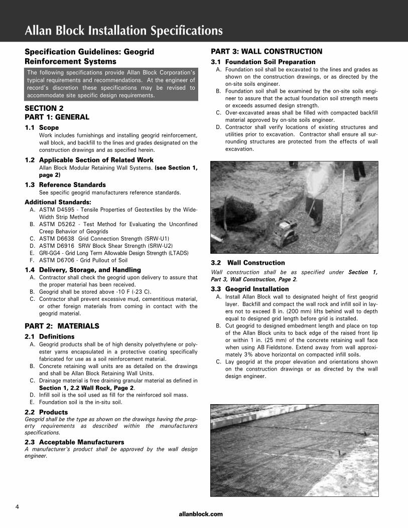
PART 3: WALL CONSTRUCTION3.1 Foundation Soil Preparation A. Foundation soil shall be excavated to the lines and grades as
shown on the construction drawings, or as directed by theon-site soils engineer.
B. Foundation soil shall be examined by the on-site soils engi-neer to assure that the actual foundation soil strength meetsor exceeds assumed design strength.
C. Over-excavated areas shall be filled with compacted backfillmaterial approved by on-site soils engineer.
D. Contractor shall verify locations of existing structures andutilities prior to excavation. Contractor shall ensure all sur-rounding structures are protected from the effects of wallexcavation.
3.2 Wall ConstructionWall construction shall be as specified under Section 1, Part 3, Wall Construction, Page 2.
3.3 Geogrid Installation A. Install Allan Block wall to designated height of first geogrid
layer. Backfill and compact the wall rock and infill soil in lay-ers not to exceed 8 in. (200 mm) lifts behind wall to depthequal to designed grid length before grid is installed.
B. Cut geogrid to designed embedment length and place on topof the Allan Block units to back edge of the raised front lipor within 1 in. (25 mm) of the concrete retaining wall facewhen using AB Fieldstone. Extend away from wall approxi-mately 3% above horizontal on compacted infill soils.
C. Lay geogrid at the proper elevation and orientations shownon the construction drawings or as directed by the walldesign engineer.
4
Specification Guidelines: GeogridReinforcement SystemsThe following specifications provide Allan Block Corporation'stypical requirements and recommendations. At the engineer ofrecord's discretion these specifications may be revised toaccommodate site specific design requirements.
SECTION 2PART 1: GENERAL1.1 Scope Work includes furnishings and installing geogrid reinforcement,
wall block, and backfill to the lines and grades designated on theconstruction drawings and as specified herein.
1.2 Applicable Section of Related Work Allan Block Modular Retaining Wall Systems. (see Section 1,
page 2)
1.3 Reference Standards See specific geogrid manufacturers reference standards.
Additional Standards: A. ASTM D4595 - Tensile Properties of Geotextiles by the Wide-
Width Strip Method B. ASTM D5262 - Test Method for Evaluating the Unconfined
Creep Behavior of Geogrids C. ASTM D6638 Grid Connection Strength (SRW-U1) D. ASTM D6916 SRW Block Shear Strength (SRW-U2) E. GRI-GG4 - Grid Long Term Allowable Design Strength (LTADS) F. ASTM D6706 - Grid Pullout of Soil
1.4 Delivery, Storage, and Handling A. Contractor shall check the geogrid upon delivery to assure that
the proper material has been received. B. Geogrid shall be stored above -10 F (-23 C). C. Contractor shall prevent excessive mud, cementitious material,
or other foreign materials from coming in contact with thegeogrid material.
PART 2: MATERIALS2.1 Definitions A. Geogrid products shall be of high density polyethylene or poly-
ester yarns encapsulated in a protective coating specificallyfabricated for use as a soil reinforcement material.
B. Concrete retaining wall units are as detailed on the drawingsand shall be Allan Block Retaining Wall Units.
C. Drainage material is free draining granular material as defined inSection 1, 2.2 Wall Rock, Page 2.
D. Infill soil is the soil used as fill for the reinforced soil mass. E. Foundation soil is the in-situ soil.
2.2 ProductsGeogrid shall be the type as shown on the drawings having the prop-erty requirements as described within the manufacturers specifications.
2.3 Acceptable ManufacturersA manufacturer's product shall be approved by the wall design engineer.
D. When fill is placed and compaction cannot bedefined in terms of Standard Proctor Density, then compactionshall be performed using ordinary compaction process and com-pacted so that no deformation is observed from the compactionequipment or to the satisfaction of the engineer of record or thesite soils engineer.
E. Tracked construction equipment shall not be operated directlyon the geogrid. A minimum fill thickness of 6 in. (150 mm)is required prior to operation of tracked vehicles over thegeogrid. Turning of tracked vehicles should be kept to a min-imum to prevent tracks from displacing the fill and damagingthe geogrid.
F. Rubber-tired equipment may pass over the geogrid reinforce-ment at slow speeds, less than 10 mph (16 Km/h). Suddenbraking and sharp turning shall be avoided.
G. The infill soil shall be compacted to achieve 95% Standard Proctor(ASTM D698). Soil tests of the infill soil shall be submitted to theon-site soils engineer for review and approval prior to the place-ment of any material. The contractor is responsible for achievingthe specified compaction requirements. The on-site soils engineermay direct the contractor to remove, correct or amend any soilfound not in compliance with these written specifications.
H. An independent testing firm should be hired by the owner to pro-vide services.
I. Independent firm to keep inspection log and provide writtenreports at predetermined intervals to the owner.
J. Testing frequency should be set to establish a proper compactionprotocol to consistently achieve the minimum compaction require-ments set by the design requirements. If full time inspection andtesting at 8 inch (20 cm) lifts is not provided, then the followingtesting frequency should be followed:
a. One test for every 8 inches (20 cm) of vertical fill placed andcompacted, for every 25 lineal feet (7.6 m) of retaining walllength, starting on the first course of block.
b. Vary compaction test locations to cover the entire area ofreinforced zone; including the area compacted by the hand-operated compaction equipment.
c. Once protocol is deemed acceptable, testing can be con-ducted randomly at locations and frequencies determined bythe on-site soils engineer.
K. Slopes above the wall must be compacted and checked in a sim-ilar manner.
3.5 Special Considerations A. Geogrid can be interrupted by periodic penetration of a column,
pier or footing structure. B. Allan Block walls will accept vertical and horizontal reinforcing
with rebar and grout. C. If site conditions will not allow geogrid embedment length, con-
sider the following alternatives: • Masonry Reinforced Walls • Soil Nailing • Increased Wall Batter • Earth Anchors • Double Allan Block Wall • Rock Bolts • No-Fines Concrete See Design Details Page 16 and 17. D. Allan Block may be used in a wide variety of water applications as
indicated in Section 3, Part 1.8, Page 7.
allanblock.com
D. Correct orientation of the geogrid shall be verified by the con-tractor and on-site soils engineer. Strength direction is typi-cally perpendicular to wall face.
E. Follow manufacturers guidelines for overlap requirements. Incurves and corners, layout shall be as specified in DesignDetail 9-12: Using Grid With Corners and Curves,Page 14.
F. Place next course of Allan Block on top of grid and fill blockcores with wall rock to lock in place. Remove slack and foldsin grid and stake to hold in place.
G. Adjacent sheets of geogrid shall be butted against each otherat the wall face to achieve 100 percent coverage.
H. Geogrid lengths shall be continuous. Splicing parallelto the wall face is not allowed.
3.4 Fill Placement A. Infill soil shall be placed in lifts and compacted as specified under
Section 1, Part 3.4, Page 3, Unit Installation. B. Infill soil shall be placed, spread and compacted in such a
manner that minimizes the development of slack or move-ment of the geogrid.
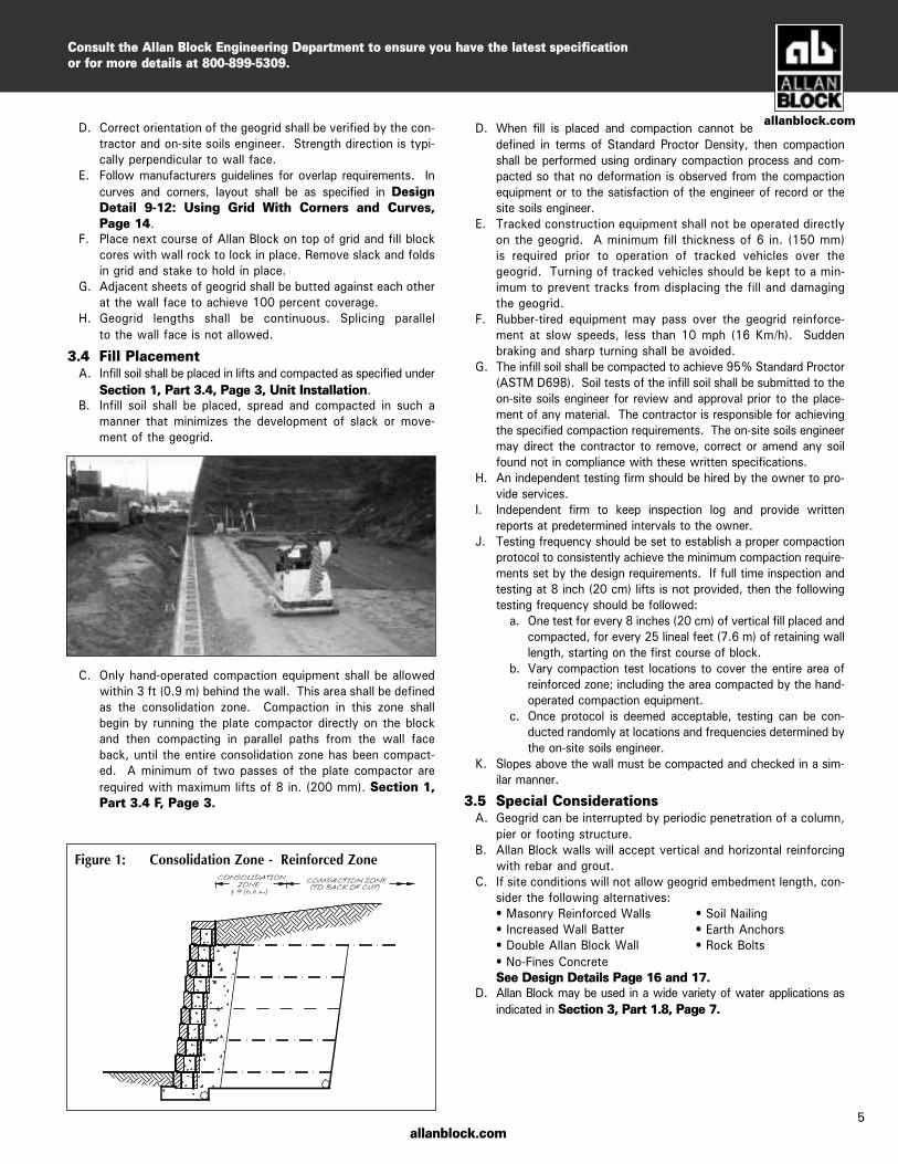
C. Only hand-operated compaction equipment shall be allowedwithin 3 ft (0.9 m) behind the wall. This area shall be definedas the consolidation zone. Compaction in this zone shallbegin by running the plate compactor directly on the blockand then compacting in parallel paths from the wall faceback, until the entire consolidation zone has been compact-ed. A minimum of two passes of the plate compactor arerequired with maximum lifts of 8 in. (200 mm). Section 1,Part 3.4 F, Page 3.
5
Figure 1: Consolidation Zone - Reinforced Zone
allanblock.com
Consult the Allan Block Engineering Department to ensure you have the latest specificationor for more details at 800-899-5309.
allanblock.com
Allan Block Water Management
Specification Guidelines:Water ManagementThe following specifications provide Allan Block Corporation's typicalrequirements and recommendations. At the engineer of record's discre-tion these specifications may be revised to accommodate site specificdesign requirements.
SECTION 3PART 1: GENERAL DRAINAGE1.1 Surface DrainageRainfall or other water sources such as irrigation activities collectedby the ground surface atop the retaining wall can be defined as sur-face water. Retaining wall design shall take into consideration themanagement of this water.
A. At the end of each day’s construction and at final completion,grade the backfill to avoid water accumulation behind the wallor in the reinforced zone.
B. Surface water must not be allowed to pond or be trapped in thearea above the wall or at the toe of the wall.
C. Existing slopes adjacent to retaining wall or slopes created dur-ing the grading process shall include drainage details so thatsurface water will not be allowed to drain over the top of theslope face and/or wall. This may require a combination ofberms and surface drainage ditches.
D. Irrigation activities at the site shall be done in a controlled andreasonable manner. If an irrigation system is employed, thedesign engineer or irrigation manufacturer shall provide detailsand specification for required equipment to ensure against overirrigation which could damage the structural integrity of theretaining wall system.
E. Surface water that cannot be diverted from the wall must becollected with surface drainage swales and drained laterally inorder to disperse the water around the wall structure.Construction of a typical swale system shall be in accordancewith Design Detail 5: Swales, Page 13.
1.2 GradingThe shaping and recontouring of land in order to prepare it for sitedevelopment is grading. Site grading shall be designed to routewater around the walls.
A. Establish final grade with a positive gradient away from thewall structure. Concentrations of surface water runoff shall bemanaged by providing necessary structures, such as pavedditches, drainage swales, catch basins, etc.
B. Grading designs must divert sources of concentrated surfaceflow, such as parking lots, away from the wall.
1.3 Drainage SystemThe internal drainage systems of the retaining wall can be describedas the means of eliminating the buildup of incidental water whichinfiltrates the soils behind the wall. Drainage system design will
be a function of the water conditions on the site. Possible drainagefacilities include Toe and Heel drainage collection pipes and blanketor chimney rock drains or others. Design engineer shall determinethe required drainage facilities to completely drain the retainingwall structure for each particular site condition.
A. All walls will be constructed with a minimum of 12 in. (300 mm) of wall rock directly behind the wall facing. Thematerial shall meet or exceed the specification for wall rockoutlined in Section 1, 2.2 Wall Rock, Page 2.
B. The drainage collection pipe, drain pipe, shall be a 4 in. (100 mm) perforated or slotted PVC, or corrugated HDPEpipe as approved by engineer of record.
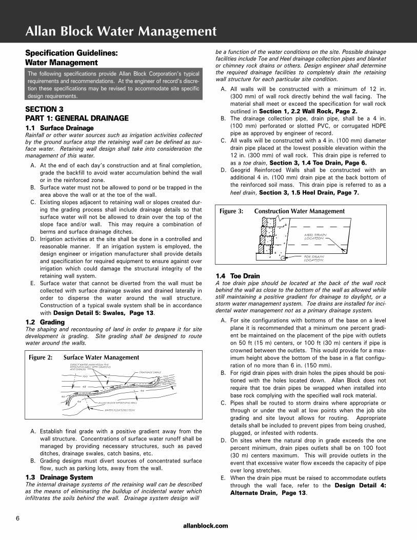
C. All walls will be constructed with a 4 in. (100 mm) diameterdrain pipe placed at the lowest possible elevation within the12 in. (300 mm) of wall rock. This drain pipe is referred toas a toe drain, Section 3, 1.4 Toe Drain, Page 6.
D. Geogrid Reinforced Walls shall be constructed with an additional 4 in. (100 mm) drain pipe at the back bottom ofthe reinforced soil mass. This drain pipe is referred to as aheel drain, Section 3, 1.5 Heel Drain, Page 7.
1.4 Toe DrainA toe drain pipe should be located at the back of the wall rockbehind the wall as close to the bottom of the wall as allowed whilestill maintaining a positive gradient for drainage to daylight, or astorm water management system. Toe drains are installed for inci-dental water management not as a primary drainage system.
A. For site configurations with bottoms of the base on a levelplane it is recommended that a minimum one percent gradi-ent be maintained on the placement of the pipe with outletson 50 ft (15 m) centers, or 100 ft (30 m) centers if pipe iscrowned between the outlets. This would provide for a max-imum height above the bottom of the base in a flat configu-ration of no more than 6 in. (150 mm).
B. For rigid drain pipes with drain holes the pipes should be posi-tioned with the holes located down. Allan Block does notrequire that toe drain pipes be wrapped when installed intobase rock complying with the specified wall rock material.
C. Pipes shall be routed to storm drains where appropriate orthrough or under the wall at low points when the job sitegrading and site layout allows for routing. Appropriatedetails shall be included to prevent pipes from being crushed,plugged, or infested with rodents.
D. On sites where the natural drop in grade exceeds the onepercent minimum, drain pipes outlets shall be on 100 foot(30 m) centers maximum. This will provide outlets in theevent that excessive water flow exceeds the capacity of pipeover long stretches.
E. When the drain pipe must be raised to accommodate outletsthrough the wall face, refer to the Design Detail 4:Alternate Drain, Page 13.
Figure 3: Construction Water Management
Figure 2: Surface Water Management
6

1.5 Heel DrainThe purpose of the heel drain is to pick up any water that migratesfrom behind the retaining wall structure at the cut and route thewater away from the reinforced mass during the constructionprocess and for incidental water for the life of the structure.
A. The piping used at the back of the reinforced mass shall havea one percent minimum gradient over the length, but it is notcritical for it to be positioned at the very bottom of the cut.The heel drain should be vented at 100 ft (30 m) intervalsalong the entire length of the wall and should not be tied intothe toe drain system.
B. The pipe may be a rigid pipe with holes at the bottom with anintegral sock encasing the pipe or a corrugated perforated flexiblepipe with a sock to filter out fines when required based on soilconditions. For infill soils with a high percentage of sand and/orgravel the heel drain pipe does not need to be surrounded by wallrock. When working with soils containing fine grained cohesivesoils having a PI of greater than 6 and LL of 30 or greater, 1 ft3.(.03 m3) of drainage rock is required around the pipe for each 1ft (30 cm) of pipe length.
1.6 Ground WaterGround water can be defined as water that occurs within the soil.It may be present because of surface infiltration or water tablefluctuation. Ground water movement must not be allowed tocome in contact with the retaining wall.
A. If water is encountered in the area of the wall during exca-vation or construction, a drainage system (chimney, compos-ite or blanket) must be installed as directed by the walldesign engineer.
B. Standard retaining wall designs do not include hydrostaticforces associated with the presence of ground water. If ade-quate drainage is not provided the retaining wall design mustconsider the presence of the water.
C. When non-free draining soils (soils with friction angles less than30 degrees) are used in the reinforced zone, the incorporation ofa chimney and blanket drain should be added to minimize thewater penetration into the reinforced mass. Refer to DesignDetail 6: Chimney and Blanket Drain, Page 13.
a. Drain material to be consistent with wall rock material.For more information on wall rock material seeSection 1, 2.1 Modular Wall Units, Page 2.
b. Manufactured chimney and blanket drains to beapproved by the geotechnical and/or the local engineerof record prior to use.
1.7 Concentrated Water SourcesAll collection devices such as roof downspouts, stormsewers, and curb gutters are concentrated water sources. They must bedesigned to accommodate maximum flow rates and to vent outside of thewall area.
A. All roof downspouts of nearby structures shall be sized withadequate capacity to carry storm water from the roof awayfrom the wall area. They shall be connected to a drainage sys-tem in closed pipe and routed around the retaining wall area.
B. Site layout must take into account locations of retaining wallstructures and all site drainage paths. Drainage paths shouldalways be away from retaining wall structures.
C. Storm sewers and catch basins shall be located away fromretaining wall structures and designed so as not to introduceany incidental water into the reinforced soil mass.
D. A path to route storm sewer overflow must be incorporated into thesite layout to direct water away from the retaining wall structure.
1.8 Water ApplicationRetaining walls constructed in conditions that allow standing or mov-ing water to come in contact with the wall face are considered waterapplications. These walls require specific design and constructionsteps to ensure performance.Refer to Design Detail 7 and 8: Water Applications, Page 13.
A. The wall rock should be placed to the limits of the geogrid lengthsup to a height equal to 12 inches (30 cm) higher than the deter-mined high water mark. If the high water mark is unknown, theentire infill zone should be constructed with wall rock.
B. The drain pipe should be raised to the low water elevation to aid inthe evacuation of water from the reinforced mass as water levelfluctuates.
C. Embankment protection fabric should be used under the infill massand up the back of the infill mass to a height of 12 inches (30 cm)higher than the determined high water mark.
a. Embankment protection fabric is used to stabilize rip rap andfoundation soils in water applications and to separate infillmaterials from the retained soils. This fabric should permit thepassage of fines to preclude clogging of the material.Embankment protection fabric shall be a high strengthpolypropylene monofilament material designed to meet orexceed typical NTPEP specifications; stabilized against ultravio-let (UV) degradation and typically meets or exceeds the valuesin Table 1.
D. For walls having moving water or wave action, natural or manufac-tured rip-rap in front of the wall to protect the toe of the wall fromscour effects is recommended.
allanblock.com7
allanblock.com
Mechanical DeterminationProperty Method
Tensile Strength = 225 lbs/in (39.4 kN/m) ASTM D-4595
Puncture Strength = 950 lbs (4228 N) ASTM D-6241
Apparent Opening Size (AOS)= U.S. Sieve #70 (0.212 mm)
Trapezoidal Tear = 100 lbs (445 N) ASTM D-4533
Percent Open Area = 4% COE-02215
Permeability = 0.01 cm/sec ASTM D-4491
Table 1: Embankment Protection Fabric Specifications
ASTM D-4751
Figure 4B: Internal Blanket and Chimney Drain
Figure 4A: Internal Blanket
Consult the Allan Block Engineering Department to ensure you have the latest specificationor for more details at 800-899-5309.
ASTM C1372 Standard Specifications for Segmental Retaining Wall Units
Specification Guidelines:Product Specifications forSegmental Retaining Wall Units The following summarizes the contents of ASTM C1372 and keycomponents relevant when specifying modular concrete blockfor use in structural retaining wall designs. A copy of the fullstandard is available upon request. This summary attempts toprovide the information which is most commonly used, butAllan Block does not claim that all information contained in thestandard is represented.
SECTION 4 1. Scope1.1 This specification covers dry-cast segmental retaining wall units
of concrete, machine–made from hydraulic cement, water, andsuitable mineral aggregates with or without the inclusion ofother materials. The units are intended for use in the construc-tion of mortarless segmental retaining walls.
5. Physical Requirements 5.1 At the time of delivery to the work site, the units shall conform
to the physical requirements of Table 2 when tested in accor-dance with 8.2.
5.2 Freeze-Thaw Durability — In areas where repeated freezing andthawing under saturated conditions occur, freeze-thaw durabil-ity shall be demonstrated by test or by proven field perform-ance that the segmental retaining wall units have adequatedurability for the intended use. When testing is required by thespecifier to demonstrate freeze-thaw durability, the units shallbe tested in accordance with 8.3.
5.2.1 Specimens shall comply with either of the following: (1) the weight loss of each of five test specimens at the con-clusion of 100 cycles shall not exceed 1 % of its initial weight;or (2) the weight loss of each of four of the five test specimensat the conclusion of 150 cycles shall not exceed 1.5 % of itsinitial weight.
6. Permissible Variations in Dimensions6.1 Overall dimensions for width, height, and length shall differ
by not more than ± 1/8 in. (3.2 mm) from specified standarddimensions.
6.1.1 Dimensional tolerance requirements for width shall bewaived for architectural surfaces.
7. Finish and Appearance7.1 All units shall be sound and free of cracks or other defects
that interfere with the proper placement of the unit or signif-icantly impair the strength or permanence of the construc-tion. Minor cracks incidental to the usual method of manu-facture or minor chipping resulting from customary methodsof handling in shipment and delivery, are not grounds forrejection.
7.2 Where units are to be used in exposed wall construction, theface or faces that are to be exposed shall not show chips orcracks, not otherwise permitted, or other imperfections whenviewed from a distance of not less than 20 ft (6.1 m) under dif-fused lighting.
7.2.1Five percent of a shipment containing chips not larger than1 in. (25 mm) in any dimension, or cracks not wider than0.02 in. (0.5 mm) and not longer than 25 % of the nominalheight of the unit is permitted.
7.3 The color and texture of units shall be specified by the pur-chaser. The finished surface that will be exposed in placeshall conform to an approved sample consisting of not lessthan four units, representing the range of texture and colorpermitted.
8. Sampling and Testing8.1 The purchaser or authorized representative shall be
accorded proper facilities to inspect and sample units atthe place of manufacture from the lots ready for delivery.
8.2 Sample and test units for compressive strength, absorption,and dimensional tolerances in accordance with Test MethodsASTM C140.
8.3 When required, sample and test five specimens for freeze-thaw durability in water in accordance with Test MethodASTM C1262. Freeze-thaw durability shall be based on testsof units made with the same materials, concrete mix design,manufacturing process, and curing method, conducted notmore than 24 months prior to delivery.
9. Compliance9.1 If a sample fails to conform to the specified requirements, the
manufacturer shall be permitted to remove units from the ship-ment. A new sample shall be selected by the purchaser fromremaining units from the shipment with a similar configuration anddimension and tested at the expense of the manufacturer. If thesecond sample meets the specified requirements, the remainingportion of the shipment represented by the sample meets thespecified requirements. If the second sample fails to meet thespecified requirements, the remaining portion of the shipment rep-resented by the sample fails to meet the specified requirements.
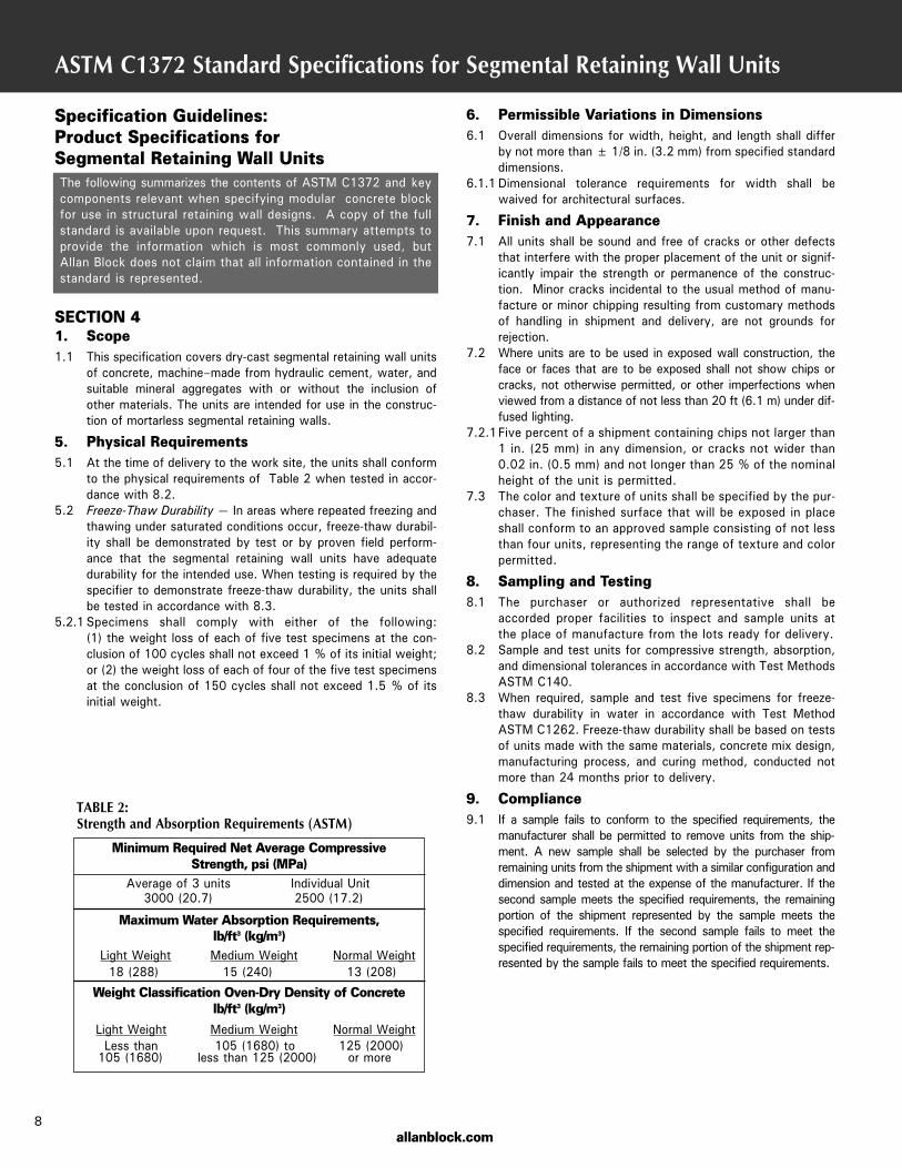
TABLE 2: Strength and Absorption Requirements (ASTM)
8allanblock.com
Minimum Required Net Average Compressive Strength, psi (MPa)
Average of 3 units Individual Unit3000 (20.7) 2500 (17.2)
Maximum Water Absorption Requirements, lb/ft3 (kg/m3)
Light Weight Medium Weight Normal Weight18 (288) 15 (240) 13 (208)
Weight Classification Oven-Dry Density of Concrete lb/ft3 (kg/m3)
Light Weight Medium Weight Normal WeightLess than 105 (1680) to 125 (2000)105 (1680) less than 125 (2000) or more
ASTM C1262 Standard Test Method for Evaluating the Freeze-Thaw Durabilityof Manufactured Concrete Masonry Units and Related Concrete Units
The following summarizes the contents of ASTM C1262 and keycomponents of the test methods used to determine relative freezethaw durability. This does not provide a comparison to field per-formance but a systematic approach to testing. A copy of the fullstandard is available upon request. This summary attempts toprovide the information which is most commonly used, but AllanBlock does not claim that all information contained in the standardis represented.
SECTION 5 1. Scope1.1 This test method covers the resistance to freezing and thawing
of dry-cast segmental retaining wall (SRW) units (seeSpecification C1372) and related concrete units. Units are test-ed in a test solution that is either water or 3 % saline solutiondepending on the intended use of the units in actual service.
Note 1 — Related concrete units include units such as hollow andsolid concrete masonry units, concrete brick, and concreteroof pavers.
4. Significance and Use4.1 The procedure described in this test method is intended to deter-
mine the effects of freezing and thawing on SRW and relatedunits in the presence of water or saline solution.
4.2 The procedure is not intended to provide a quantitative measureto determine an expected length of service for a specific type ofconcrete unit.
6. Sampling and Preparation of Test Methods6.1 Selection of Test Units — Select five whole SRW units rep-
resentative of the lot from which they are selected. The unitsshall be free from visible cracks or structural defects.
6.2 Number of Specimens — Test specimens shall consist of solidcoupons saw-cut from full sized units. Do not saw-cut testspecimens from units that have been previously oven-dried.Do not subject test specimens to oven-drying prior to comple-tion of freeze-thaw testing.
6.2.1Cut one coupon from each of the five sampled units. Cut thecoupon from the exposed surface of the unit as the unit is usedin service unless the exposed surface is an architectural or othernonplanar surface (see Note 6). In the case of a unit with anexposed architectural or other nonplanar surface, cut the couponfrom another flat molded surface ideally as far as possible fromthe architectural or other nonplanar face and in no case less than2 in. (50 mm) from that surface. Immediately following saw-cut-ting, remove loose particles and residue from the coupon by rins-ing in tap water and brushing with a soft bristle brush. Do notfully immerse coupons in water. Each specimen shall be markedwith a unique identification number on the non-molded surfaceof the specimen.
Note 6 — Split-faced surfaces are the most common surfaces usedto provide an architectural appearance to segmental retainingwalls. However, other means could be used to obtain similararchitectural effects like tumbling, grinding, and slumping.
7. Procedure7.1 Specimen Conditioning:7.1.1After preparation of the freeze-thaw test specimens in accor-
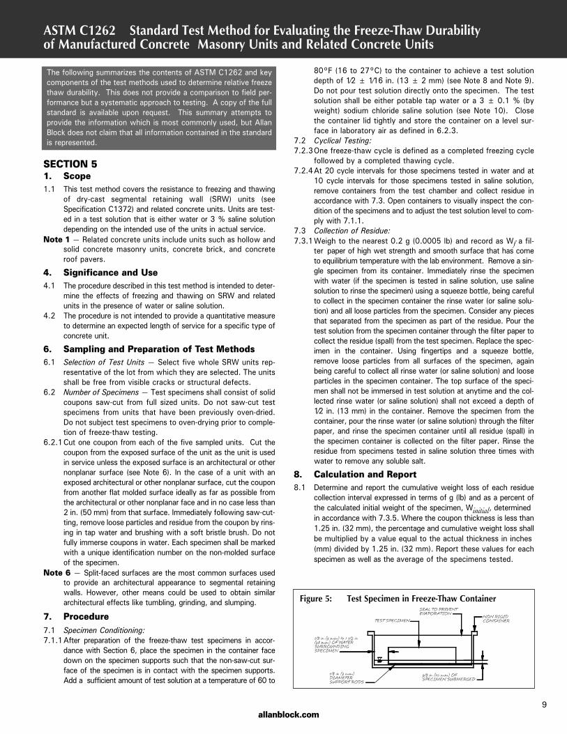
dance with Section 6, place the specimen in the container facedown on the specimen supports such that the non-saw-cut sur-face of the specimen is in contact with the specimen supports.Add a sufficient amount of test solution at a temperature of 60 to
9
80°F (16 to 27°C) to the container to achieve a test solutiondepth of 1⁄2 ± 1⁄16 in. (13 ± 2 mm) (see Note 8 and Note 9).Do not pour test solution directly onto the specimen. The testsolution shall be either potable tap water or a 3 ± 0.1 % (byweight) sodium chloride saline solution (see Note 10). Closethe container lid tightly and store the container on a level sur-face in laboratory air as defined in 6.2.3.
7.2 Cyclical Testing:7.2.3One freeze-thaw cycle is defined as a completed freezing cycle
followed by a completed thawing cycle.7.2.4At 20 cycle intervals for those specimens tested in water and at
10 cycle intervals for those specimens tested in saline solution,remove containers from the test chamber and collect residue inaccordance with 7.3. Open containers to visually inspect the con-dition of the specimens and to adjust the test solution level to com-ply with 7.1.1.
7.3 Collection of Residue:7.3.1Weigh to the nearest 0.2 g (0.0005 lb) and record as Wf a fil-
ter paper of high wet strength and smooth surface that has cometo equilibrium temperature with the lab environment. Remove a sin-gle specimen from its container. Immediately rinse the specimenwith water (if the specimen is tested in saline solution, use salinesolution to rinse the specimen) using a squeeze bottle, being carefulto collect in the specimen container the rinse water (or saline solu-tion) and all loose particles from the specimen. Consider any piecesthat separated from the specimen as part of the residue. Pour thetest solution from the specimen container through the filter paper tocollect the residue (spall) from the test specimen. Replace the spec-imen in the container. Using fingertips and a squeeze bottle,remove loose particles from all surfaces of the specimen, againbeing careful to collect all rinse water (or saline solution) and looseparticles in the specimen container. The top surface of the speci-men shall not be immersed in test solution at anytime and the col-lected rinse water (or saline solution) shall not exceed a depth of1⁄2 in. (13 mm) in the container. Remove the specimen from thecontainer, pour the rinse water (or saline solution) through the filterpaper, and rinse the specimen container until all residue (spall) inthe specimen container is collected on the filter paper. Rinse theresidue from specimens tested in saline solution three times withwater to remove any soluble salt.
8. Calculation and Report8.1 Determine and report the cumulative weight loss of each residue
collection interval expressed in terms of g (lb) and as a percent ofthe calculated initial weight of the specimen, Winitial, determinedin accordance with 7.3.5. Where the coupon thickness is less than1.25 in. (32 mm), the percentage and cumulative weight loss shallbe multiplied by a value equal to the actual thickness in inches(mm) divided by 1.25 in. (32 mm). Report these values for eachspecimen as well as the average of the specimens tested.
Figure 5: Test Specimen in Freeze-Thaw Container
allanblock.com
allanblock.com
Wall Design Checklist
To ensure that the basics are covered in your wall design wehave prepared the following wall design checklist. It may alsobe used by someone checking your work to provide an outlinefor a consistent review process. For a complete discussion, seethe Best Practices for SRW Design document at allanblock.com.
Review Wall Design Plans For Special Conditions:
• Site Drainage Layout• Global Stability• Government Regulations• High Water Table• Seismic Design Requirements• Above Wall Considerations
Review Wall Design Plans For:• Overall Length of Wall• Station Points• Plan Layout• Elevations• Grades or Slopes Above or Below Walls• Soil Conditions
Retained Soil Friction AngleInfill Soil Friction AngleFoundation Soil Friction AngleCohesion for Foundation SoilSoil Settlement Potential
• Water ManagementAbove GradeBelow GradeExcess Irrigation
• Locations of Catch Basins and Utilities• Compliance to Specifications• Surcharges (live, dead, and location)• Temporary Construction Loads• Snow or Storage Loads• Special Provisions
Design Review:• Grid Length• Grid Spacing• Grid Placed on Consistent Courses• Design Factors of Safety
SlidingOverturningBearingGrid OverstressPullout from SoilPullout from BlockInternal CompoundGlobalSeismic
• Water Management DetailsSurface Water SourcesSubsurface Water SourcesDetails for Low Permeability SoilsLocation and Venting of Toe and Heel Drains
• Overall Quantity EstimatesBlockGridWall Rock
• Construction Details• General Notes and Specifications
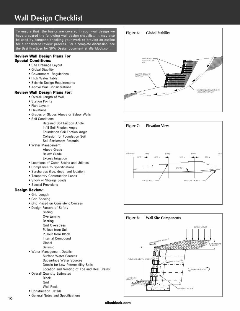
Figure 6: Global Stability
Figure 7: Elevation View
Figure 8: Wall Site Components
10
allanblock.com
Construction and Inspection Checklist
Review Construction Details And Procedures:
A. Mark station points for top and bottom of wall elevations andchanges in wall direction.
B. Identify changes in grid lengths, location of grids, and types ofgrid to be used.
C. Determine and locate proper base size for each section of wall.
D. Verify that the correct type and color of block has been orderedand delivered to the job.
E. Verify that the foundation soil and retained soil conform todesign requirements.
F. Verify that infill soil meets design standards.
G. Verify that compaction testing will be performed, who is respon-sible, at what intervals of locations along the wall, and whatcoordination will be required.
H. Determine what method will be used to verify constructionmaterials, methods, and sequence of construction. (ie: writtendocumentation of as built, full time inspector on site, photo-graphic documentation.)
I. Wall contractor is responsible for quality control of wall installa-tion per the approved plans. The owner or owner’s representa-tive is responsible for engineering and quality assurance of theproject.
We have prepared the following Construction and InspectionChecklist to provide a list of items covering the basics for yourretaining wall project. It may also be used during the biddingprocess to ensure that all special provisions are complied with.Always check your local building codes, document any changesto the plan in writing and notify the wall design engineer withany concerns on water management.
Review Wall Design Plans For:
A. Compliance of Site to Latest Site Plan• Does the site plan and wall layout coincide with current Site
Conditions?• Have all slopes above and below the walls been taken into
account on the plans?• Do the section drawings match the topography of the job-site?• Have site utilities been accounted for?• Are there any recommendations for changes to the site plans
to accommodate the wall?
B. Review of Reported Soil Conditions with On-SiteSoils Engineer
• Are on-site soils consistent with soil parameters used in walldesign?
• Does the site show indications of multiple types of soil, andhas this been accounted for?
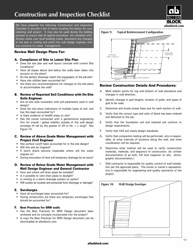
• Is there evidence of landfill areas on site?• Has the owner contracted with a geotechnical engineering
firm for overall / global stability outside of the wall designenvelope (H tall by the greater of 2H or He + L long)? SeeFigure 10.
C. Review of Above Grade Water Management withProject Civil Engineer
• Has surface runoff been accounted for in the site design?• Will this site be irrigated?• If storm drains become inoperable where will the water
migrate to?• During renovation of land will temporary drainage be an issue?
D. Review of Below Grade Water Management withWall Design Engineer and General Contractor
• How and where will drain pipes be installed?• Is it possible to vent drain pipes to daylight?• Is venting to a storm drainage system an option?• Will outlets be located and protected from blockage or damage?
E. Surcharges• Have all surcharges been accounted for?• During construction are there any temporary surcharges that
should be accounted for?
F. Best Practices for SRW walls• Has the Best Practices for SRW Design document been
reviewed and its concepts incorporated into the project?• A copy the Best Practices for SRW Design document can be
downloaded at allanblock.com.
Figure 9: Typical Reinforcement Configuration
Figure 10: Wall Design Envelope
11
allanblock.com
Design Details
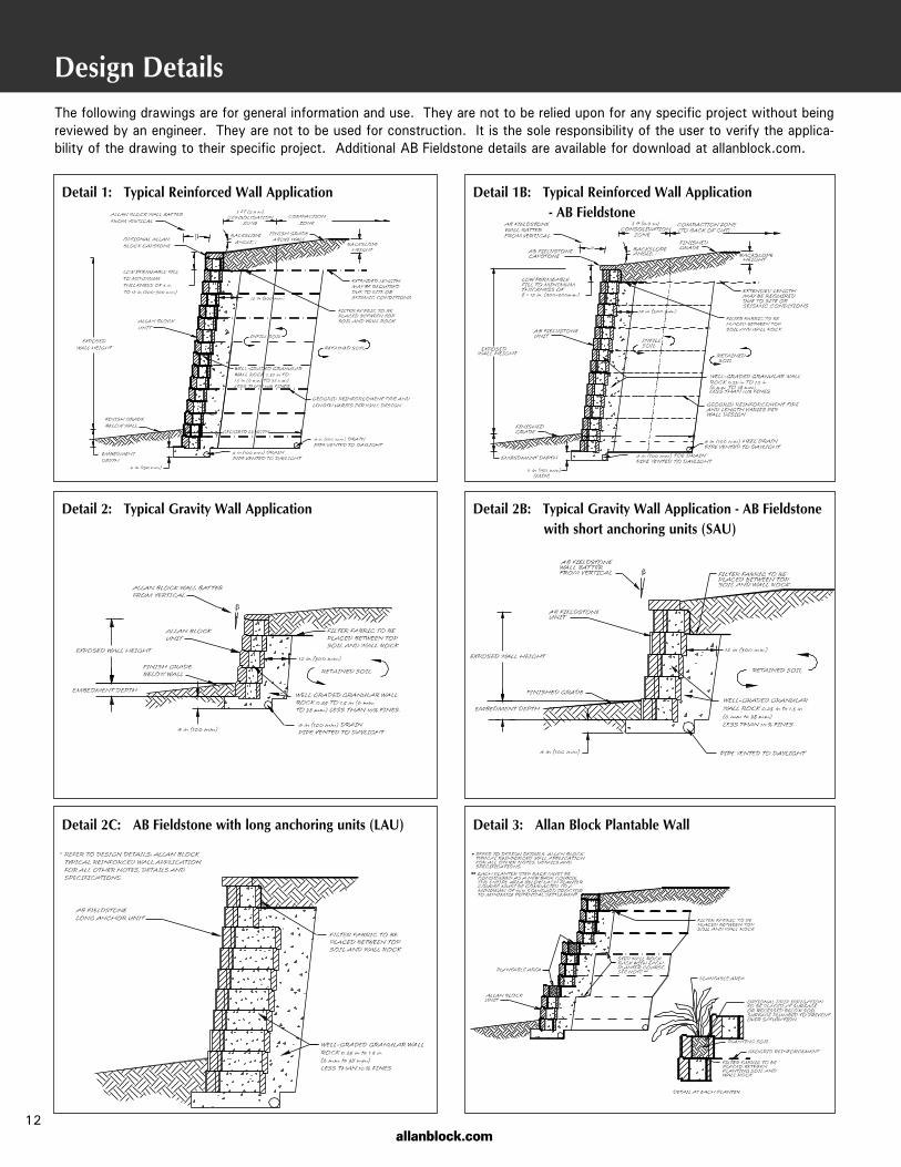
Detail 2C: AB Fieldstone with long anchoring units (LAU) Detail 3: Allan Block Plantable Wall
12allanblock.com
Detail 2: Typical Gravity Wall Application Detail 2B: Typical Gravity Wall Application - AB Fieldstonewith short anchoring units (SAU)
Detail 1: Typical Reinforced Wall Application Detail 1B: Typical Reinforced Wall Application- AB Fieldstone
The following drawings are for general information and use. They are not to be relied upon for any specific project without beingreviewed by an engineer. They are not to be used for construction. It is the sole responsibility of the user to verify the applica-bility of the drawing to their specific project. Additional AB Fieldstone details are available for download at allanblock.com.
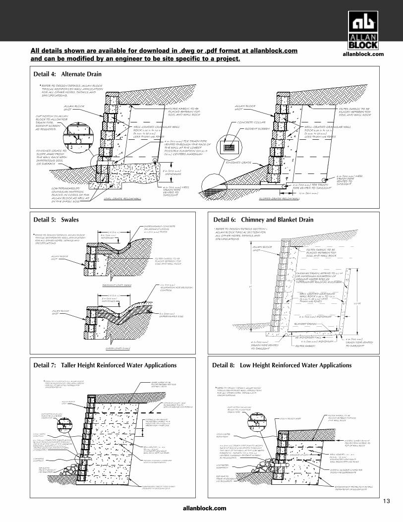
Detail 7: Taller Height Reinforced Water Applications Detail 8: Low Height Reinforced Water Applications
Detail 5: Swales Detail 6: Chimney and Blanket Drain
13
Detail 4: Alternate Drain
allanblock.com
allanblock.comAll details shown are available for download in .dwg or .pdf format at allanblock.comand can be modified by an engineer to be site specific to a project.

Design Details
Detail 13: Step Up at Base Course Detail 14: Grouted Connection
Detail 11: Inside Curve Geogrid Overlap Detail 12: Outside Curve Geogrid Overlap
Detail 9: Inside Corner Geogrid Overlap Detail 10: Outside Corner Geogrid Overlap
14allanblock.com
The following drawings are for general information and use. They are not to be relied upon for any specific project without beingreviewed by an engineer. They are not to be used for construction. It is the sole responsibility of the user to verify the applica-bility of the drawing to their specific project. Additional AB Fieldstone details are available for download at allanblock.com.
allanblock.com
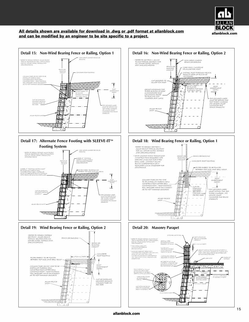
Detail 19: Wind Bearing Fence or Railing, Option 2 Detail 20: Masonry Parapet
Detail 17: Alternate Fence Footing with SLEEVE-ITFooting System
Detail 18: Wind Bearing Fence or Railing, Option 1
Detail 15: Non-Wind Bearing Fence or Railing, Option 1 Detail 16: Non-Wind Bearing Fence or Railing, Option 2
15
™
allanblock.comAll details shown are available for download in .dwg or .pdf format at allanblock.comand can be modified by an engineer to be site specific to a project.
allanblock.com
Design Details
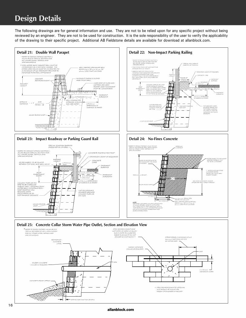
Detail 25: Concrete Collar Storm Water Pipe Outlet, Section and Elevation View
Detail 23: Impact Roadway or Parking Guard Rail Detail 24: No-Fines Concrete
Detail 21: Double Wall Parapet Detail 22: Non-Impact Parking Railing
16
The following drawings are for general information and use. They are not to be relied upon for any specific project without beingreviewed by an engineer. They are not to be used for construction. It is the sole responsibility of the user to verify the applicabilityof the drawing to their specific project. Additional AB Fieldstone details are available for download at allanblock.com.
allanblock.com
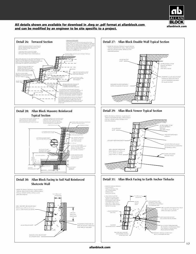
Detail 30: Allan Block Facing to Soil Nail Reinforced Shotcrete Wall
Detail 31: Allan Block Facing to Earth Anchor Tiebacks
Detail 28: Allan Block Masonry Reinforced Typical Section
Detail 29: Allan Block Veneer Typical Section
Detail 26: Terraced Section Detail 27: Allan Block Double Wall Typical Section
17
allanblock.comAll details shown are available for download in .dwg or .pdf format at allanblock.com and can be modified by an engineer to be site specific to a project.
Design Methods
The following information is intended to provide insight into thebasic concepts behind an Allan Block retaining wall design. A com-plete review of the methodology and the equations may be foundby reviewing the Allan Block Engineering Manual.
Allan Block walls are most often designed and constructed as eithergravity walls or coherent gravity masses, but can be used in manydifferent types of retaining wall applications;
Gravity Walls are structures that resist the pressures from theretained soil with the weight of the facing. Under optimum conditionsAllan Block gravity walls may be constructed up to 5.5 ft (1.7 m).
Coherent Gravity Masses act as large composite structures.These structures are a flexible unified mass that resist the forcesfrom the retained soil in the same manner as a simple gravity wall.These composite structures are composed of geogrid reinforced soilmasses with Allan Block Retaining Walls used as a durable, aesthet-ically pleasing, facing material.
Other reinforcement options include Tie Back Walls or MasonryReinforcement. Tie Backs utilize Allan Block as a hard facing withsome type of anchor used to tie back the facing. Designs of this typedevelop loads at the face and end of the anchor and do not performas a coherent gravity mass. Masonry reinforcement applications usegrout and rebar through the cores of the Allan Block to create a highstrength cantilever wall.
Allan Block Corporation has developed several tools to help thedesign engineer through the design process. Available toolsinclude:
Best Practices for SRW Design — providing better designconstruction practices in the field and to help drive the industrytoward Zero Wall Failures.
Allan Block Engineering Manual — providing detailed calcu-lations and commentary for the methods and processes used inthe design procedure.
AB Walls™ 3D — a comprehensive design tool which outputsprofessional quality construction drawings with technical supportdata. It allows designers to transfer a conceptual layout from asite plan to a complete wall solution and then export it to DXFCAD format as well as to the 3D Modeling Program SketchUp. Inaddition, designers can generate elevations, plans, and multiplecross sectional views of their retaining wall projects.
Hand Calculations — a MathCAD based file that contains all ofthe detailed calculations for the engineer to review as well as pro-viding the engineer the ability to revise the equations to fit theparticular need of the job in process while providing a method tocross check the output of AB Walls™ 3D.
The basic elements of the design process require an understanding ofthe properties of the soils to be used behind and below the retainingwall, terrain changes above or below the retaining structure, sur-charges located above the wall, and seismic loading if appropriate.
The design calculation process has two categories of stability to bechecked; external stability and internal stability.
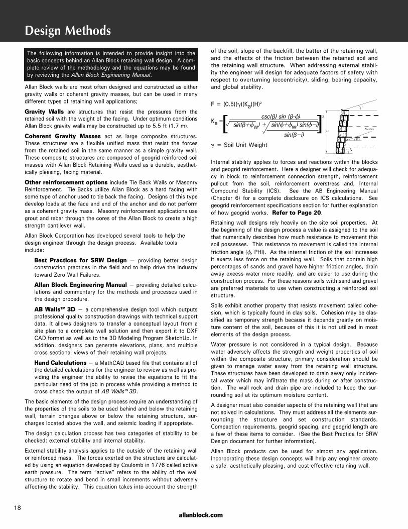
External stability analysis applies to the outside of the retaining wallor reinforced mass. The forces exerted on the structure are calculat-ed by using an equation developed by Coulomb in 1776 called activeearth pressure. The term “active” refers to the ability of the wallstructure to rotate and bend in small increments without adverselyaffecting the stability. This equation takes into account the strength
of the soil, slope of the backfill, the batter of the retaining wall,and the effects of the friction between the retained soil andthe retaining wall structure. When addressing external stabil-ity the engineer will design for adequate factors of safety withrespect to overturning (eccentricity), sliding, bearing capacity,and global stability.
Internal stability applies to forces and reactions within the blocksand geogrid reinforcement. Here a designer will check for adequa-cy in block to reinforcement connection strength, reinforcementpullout from the soil, reinforcement overstress and, InternalCompound Stability (ICS). See the AB Engineering Manual(Chapter 6) for a complete disclosure on ICS calculations. Seegeogrid reinforcement specifications section for further explanationof how geogrid works. Refer to Page 20.
Retaining wall designs rely heavily on the site soil properties. Atthe beginning of the design process a value is assigned to the soilthat numerically describes how much resistance to movement thissoil possesses. This resistance to movement is called the internalfriction angle (Ñ, PHI). As the internal friction of the soil increasesit exerts less force on the retaining wall. Soils that contain highpercentages of sands and gravel have higher friction angles, drainaway excess water more readily, and are easier to use during theconstruction process. For these reasons soils with sand and gravelare preferred materials to use when constructing a reinforced soilstructure.
Soils exhibit another property that resists movement called cohe-sion, which is typically found in clay soils. Cohesion may be clas-sified as temporary strength because it depends greatly on mois-ture content of the soil, because of this it is not utilized in mostelements of the design process.
Water pressure is not considered in a typical design. Becausewater adversely affects the strength and weight properties of soilwithin the composite structure, primary consideration should begiven to manage water away from the retaining wall structure.These structures have been developed to drain away only inciden-tal water which may infiltrate the mass during or after construc-tion. The wall rock and drain pipe are included to keep the sur-rounding soil at its optimum moisture content.
A designer must also consider aspects of the retaining wall that arenot solved in calculations. They must address all the elements sur-rounding the structure and set construction standards.Compaction requirements, geogrid spacing, and geogrid length area few of these items to consider. (See the Best Practice for SRWDesign document for further information).
Allan Block products can be used for almost any application.Incorporating these design concepts will help any engineer createa safe, aesthetically pleasing, and cost effective retaining wall.
F = (0.5)(Ö)(Ka)(H)2
csc(Ä) sin (Ä-Ñ)sin(ÄNÑw) N sin(ÑNÑw) sin(ÑOi)
sin(ÄOi)
Ö = Soil Unit Weight
[ ]Ka=2
18allanblock.com
allanblock.com
Allowable Construction Tolerances
19
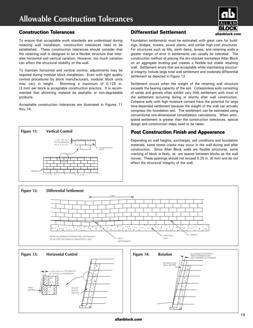
Figure 11: Vertical Control
Figure 12: Differential Settlement
Figure 13: Horizontal Control Figure 14: Rotation
Construction Tolerances
To ensure that acceptable work standards are understood duringretaining wall installation, construction tolerances need to beestablished. These construction tolerances should consider thatthe retaining wall is designed to be a flexible structure that toler-ates horizontal and vertical variation. However, too much variationcan affect the structural stability of the wall.
To maintain horizontal and vertical control, adjustments may berequired during modular block installation. Even with tight qualitycontrol procedures by block manufacturers, modular block unitsmay vary in height. Shimming a maximum of 0.125 in. (3 mm) per block is acceptable construction practice. It is recom-mended that shimming material be asphaltic or non-degradableproducts.
Acceptable construction tolerances are illustrated in Figures 11thru 14.
Differential Settlement
Foundation settlements must be estimated with great care for build-ings, bridges, towers, power plants, and similar high-cost structures.For structures such as fills, earth dams, levees, and retaining walls agreater margin of error in settlements can usually be tolerated. Theconstruction method of placing the dry-stacked mortarless Allan Blockon an aggregate leveling pad creates a flexible but stable retainingwall. Settlement errors that are acceptable while maintaining structur-al integrity include large total wall settlement and moderate differentialsettlement as depicted in Figure 12.
Settlement occurs when the weight of the retaining wall structureexceeds the bearing capacity of the soil. Cohesionless soils consistingof sands and gravels often exhibit very little settlement with most ofthe settlement occurring during or shortly after wall construction.Cohesive soils with high moisture content have the potential for largetime-depended settlement because the weight of the wall can actuallycompress the foundation soil. The settlement can be estimated usingconventional one-dimensional consolidation calculations. When antic-ipated settlement is greater than the construction tolerances, specialdesign and construction steps need to be taken.
Post Construction Finish and Appearance
Depending on wall heights, surcharges, soil conditions and foundationmaterials, some stress cracks may occur in the wall during and afterconstruction. Since Allan Block walls are flexible structures, somecracking of block is likely, as are spaces between blocks as the wallmoves. These openings should not exceed 0.25 in. (6 mm) and do notaffect the structural integrity of the wall.
allanblock.com
allanblock.com
Specification Guidelines: Geogrid Reinforcement
Every building we live and work in calls on various materials to blendstrength and functionality to create a finished product that providesus with a safe living space incorporating the amenities that wedesire. The development of geosynthetics to reinforce soil masseshas paved the way to a new industry utilizing concrete block as a fac-ing for these composite retaining wall structures.
Allan Block walls that cannot rely on the weight of the block alone toretain soil typically use geogrid reinforcement to develop a larger mass.Geogrids are flexible synthetic meshes produced from high strengthpolyester fibers encapsulated in protective coating. They work per-fectly with on-site soils and modular retaining wall products becauseof their strength, durability, workability and overall economy.
Soil reinforcement is a concept that dates back to the times ofBabylonia and the construction of the Great Wall of China when non-degradable tree branches were placed in between layers of compact-ed soil. Whether it is tree branches or coated synthetic fibers, theseproducts are used to create a reinforced coherent mass behind theretaining wall by stabilizing the mass and increasing the internalstrength of the soil.
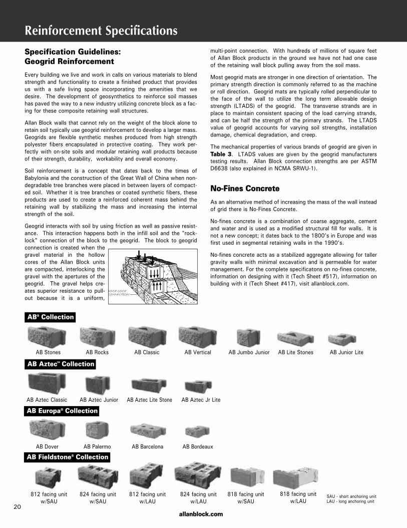
Geogrid interacts with soil by using friction as well as passive resist-ance. This interaction happens both in the infill soil and the "rock-lock" connection of the block to the geogrid. The block to geogridconnection is created when thegravel material in the hollowcores of the Allan Block unitsare compacted, interlocking thegravel with the apertures of thegeogrid. The gravel helps cre-ates superior resistance to pull-out because it is a uniform,
Reinforcement Specificationsmulti-point connection. With hundreds of millions of square feetof Allan Block products in the ground we have not had one caseof the retaining wall block pulling away from the soil mass.
Most geogrid mats are stronger in one direction of orientation. Theprimary strength direction is commonly referred to as the machineor roll direction. Geogrid mats are typically rolled perpendicular tothe face of the wall to utilize the long term allowable designstrength (LTADS) of the geogrid. The transverse strands are inplace to maintain consistent spacing of the load carrying strands,and can be half the strength of the primary strands. The LTADSvalue of geogrid accounts for varying soil strengths, installationdamage, chemical degradation, and creep.
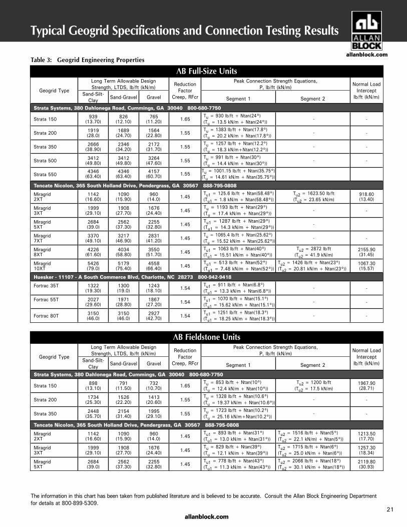
The mechanical properties of various brands of geogrid are given inTable 3. LTADS values are given by the geogrid manufacturerstesting results. Allan Block connection strengths are per ASTMD6638 (also explained in NCMA SRWU-1).
No-Fines Concrete
As an alternative method of increasing the mass of the wall insteadof grid there is No-Fines Concrete.
No-fines concrete is a combination of coarse aggregate, cementand water and is used as a modified structural fill for walls. It isnot a new concept; it dates back to the 1800’s in Europe and wasfirst used in segmental retaining walls in the 1990’s.
No-fines concrete acts as a stabilized aggregate allowing for tallergravity walls with minimal excavation and is permeable for watermanagement. For the complete specificatons on no-fines concrete,information on designing with it (Tech Sheet #517), information onbuilding with it (Tech Sheet #417), visit allanblock.com.
20
AB® Collection
AB Europa® Collection
AB Stones AB Rocks AB Classic AB Vertical AB Jumbo Junior AB Lite Stones AB Junior Lite
AB Dover AB Palermo AB Barcelona AB Bordeaux
812 facing unitw/SAU
824 facing unitw/SAU
812 facing unitw/LAU
824 facing unitw/LAU
AB Aztec Collection
AB Aztec Classic AB Aztec Junior AB Aztec Lite Stone AB Aztec Jr Lite
™
818 facing unitw/SAU
818 facing unitw/LAU
SAU - short anchoring unitLAU - long anchoring unit
AB Fieldstone® Collection
allanblock.com21
Typical Geogrid Specifications and Connection Testing Results
AB Full-Size Units
AB Fieldstone Units
Table 3: Geogrid Engineering Properties
The information in this chart has been taken from published literature and is believed to be accurate. Consult the Allan Block Engineering Department for details at 800-899-5309.
Geogrid Type
Long Term Allowable Design Strength, LTDS, lb/ft (kN/m) Reduction
Factor Creep, RFcr
Peak Connection Strength Equations, P, lb/ft (kN/m) Normal Load
Intercept lb/ft (kN/m)Sand-Silt-
Clay Sand-Gravel Gravel
Segment 1
Segment 2
Strata Systems, 380 Dahlonega Road, Cummings, GA 30040 800-680-7750
Strata 150 939 (13.70)
826 (12.10)
765 (11.20) 1.65
Tu = 930 lb/ft + Ntan(24°) (Tu = 13.5 kN/m + Ntan(24°))
- -
Strata 200 1919 (28.0)
1689 (24.70)
1564 (22.80) 1.55
Tu = 1383 lb/ft + Ntan(17.8°) (Tu = 20.2 kN/m + Ntan(17.8°))
- -
Strata 350 2666 (38.90)
2346 (34.20)
2172 (31.70) 1.55
Tu = 1257 lb/ft + Ntan(12.2°) (Tu = 18.3 kN/m+Ntan(12.2°))
- -
Strata 500 3412 (49.80)
3412 (49.80)
3264 (47.60) 1.55
Tu = 991 lb/ft + Ntan(30°) (Tu = 14.4 kN/m + Ntan(30°))
- -
Strata 5504346
(63.40)4346
(63.40)4157
(60.70) 1.55Tu = 1001.15 lb/ft + Ntan(35.75°) (Tu = 14.61 kN/m + Ntan(35.75°))
Tencate Nicolon, 365 South Holland Drive, Pendergrass, GA 30567 888-795-0808
Miragrid 2XT
1142 (16.60)
1090 (15.90)
960 (14.0) 1.45
Tu1 = 125.6 lb/ft + Ntan(58.48°) (Tu1 = 1.8 kN/m + Ntan(58.48°))
Tu2 = 1623.50 lb/ft (Tu2 = 23.65 kN/m)
918.60 (13.40)
Miragrid 3XT
1999 (29.10)
1908 (27.70)
1676 (24.40) 1.45
Tu = 1193 lb/ft + Ntan(29°) (Tu = 17.4 kN/m + Ntan(29°))
- -
Miragrid 5XT
2684 (39.0)
2562 (37.30)
2255 (32.80) 1.45
Tu1 = 1287 lb/ft + Ntan(29°) (Tu1 = 14.3 kN/m + Ntan(29°))
-
Miragrid 7XT
3370 (49.10)
3217 (46.90)
2831 (41.20) 1.45
Tu = 1065.4 lb/ft + Ntan(25.62°) (Tu = 15.52 kN/m + Ntan(25.62°))
- -
Miragrid 8XT
4226 (61.60)
4034 (58.80)
3550 (51.70) 1.45
Tu1 = 1063 lb/ft + Ntan(40°) (Tu1 = 15.51 kN/m + Ntan(40°))
Tu2 = 2872 lb/ft (Tu2 = 41.9 kN/m)
2155.90 (31.45)
Miragrid 10XT
5426 (79.0)
5179 (75.40)
4558 (66.40) 1.45
Tu1 = 513 lb/ft + Ntan(52°) (Tu1 = 7.48 kN/m + Ntan(52°))
Tu2 = 1426 lb/ft + Ntan(23°) (Tu2 = 20.81 kN/m + Ntan(23°))
1067.30 (15.57)
Huesker - 11107 - A South Commerce Blvd, Charlotte, NC 28273 800-942-9418
Fortrac 35T 1322 (19.30)
1300 (19.0)
1243 (18.10) 1.54
Tu1 = 911 lb/ft + Ntan(6.8°) (Tu1 = 13.3 kN/m + Ntan(6.8°))
- -
Fortrac 55T 2027 (29.60)
1971 (28.80)
1867 (27.20) 1.54
Tu1 = 1070 lb/ft + Ntan(15.1°) (Tu1 = 15.62 kN/m + Ntan(15.1°))
- -
Fortrac 80T 3150 (46.0)
3150 (46.0)
2927 (42.70) 1.54
Tu1 = 1251 lb/ft + Ntan(18.3°) (Tu1 = 18.25 kN/m + Ntan(18.3°))
- -
Geogrid Type
Long Term Allowable Design Strength, LTDS, lb/ft (kN/m) Reduction
Factor Creep, RFcr
Peak Connection Strength Equations, P, lb/ft (kN/m) Normal Load
Intercept lb/ft (kN/m)Sand-Silt-
Clay Sand-Gravel Gravel
Segment 1
Segment 2
Strata Systems, 380 Dahlonega Road, Cummings, GA 30040 800-680-7750
Strata 150 898 (13.10)
791 (11.50)
732 (10.70) 1.65
Tu = 853 lb/ft + Ntan(10°) (Tu = 12.4 kN/m + Ntan(10°))
Tu2 = 1200 lb/ft (Tu2 = 17.5 kN/m)
1967.90 (28.71)
Strata 200 1734 (25.30)
1526 (22.20)
1413 (20.60) 1.55
Tu = 1328 lb/ft + Ntan(10.6°) (Tu = 19.37 kN/m + Ntan(10.6°))
- -
Strata 350 2448 (35.70)
2154 (31.40)
1995 (29.10) 1.55
Tu = 1723 lb/ft + Ntan(10.2°) (Tu = 25.16 kN/m+Ntan(10.2°))
- -
Tencate Nicolon, 365 South Holland Drive, Pendergrass, GA 30567 888-795-0808
Miragrid 2XT
1142 (16.60)
1090 (15.90)
960 (14.0) 1.45
Tu1 = 893 lb/ft + Ntan(31°) (Tu1 = 13.0 kN/m + Ntan(31°))
Tu2 = 1516 lb/ft + Ntan(5°) (Tu2 = 22.1 kN/m) + Ntan(5°))
1213.50 (17.70)
Miragrid 3XT
1999 (29.10)
1908 (27.70)
1676 (24.40) 1.45
Tu = 829 lb/ft + Ntan(39°) (Tu = 12.1 kN/m + Ntan(39°))
Tu2 = 1715 lb/ft + Ntan(6°) (Tu2 = 25.0 kN/m + Ntan(6°))
1257.30 (18.34)
Miragrid 5XT
2684 (39.0)
2562 (37.30)
2255 (32.80) 1.45
Tu1 = 778 lb/ft + Ntan(43°) (Tu1 = 11.3 kN/m + Ntan(43°))
Tu2 = 2066 lb/ft + Ntan(18°) (Tu2 = 30.1 kN/m + Ntan(18°))
2119.80 (30.93)
allanblock.com
© 2019, 2015-2000 Allan Block Corporation, Bloomington, MN Phone 952-835-5309 Fax 952-835-0013, DOC. #R0901-0219
This technical specification manual will allow a wall designer tosource and reference specific information for use in developingproject documents. The information contained in this manual isfor use with Allan Block products only.
Best Practices for SRW’sEnsure Zero Wall Failuresby learning the industry’sbest practices whendesigning SRW’s.
AB Walls 3DUse our compehensivedesign software for fullproject submittals andshop drawings and 3D BIM type exportable files.Get the most powerfulSRW software available.
Check out the bestmaterials and tools
in the industryfor SRW’s.