t55-l-712 turbine engine compressor housing … turbine engine compressor housing refurbishment -...
TRANSCRIPT
NASA
Technical Memorandum 101310
AVSCOM
Technical Memorandum 88-C-006
T55-L-712 Turbine Engine Compressor
Housing Refurbishment--Plasma
Spray Project
George W. Leissler
Sverdrup Technology, Inc.NASA Lewis Research Center Group
Cleveland, Ohio
and
John S. Yuhas
Propulsion DirectorateU.S. Army Aviation Research and Technology Activity--AVSCOMLewis Research Center
Cleveland, Ohio
_l:_ta¥ _bCagC'l (I_A) 44 p CSCL 11.__
N89-1C15o
G 3/2 bUnclas
0168490
October 1988
SYSTEMS COMMAND
AVIATION R&T ACTIVITY
https://ntrs.nasa.gov/search.jsp?R=19890000785 2018-08-08T00:07:22+00:00Z

r r
Trade names or manufacturers' names are used in this report for identification
only. This usage does not constitute an official endorsement, either expressed orimplied, by the National Aeronautics and Space Administration.
T55-L-712 TURBINE ENGINE COMPRESSOR HOUSING
REFURBISHMENT - PLASMA SPRAY PROJECT
George W. LeisslerSverdrup Technology, Inc.
NASA Lewis Research Center GroupCleveland, Ohio 44135
and
John S. YuhasPropulsion Directorate
U.S. Army Aviation Research and Technology Activity - AVSCOMLewis Research CenterCleveland, Ohio 44135
0c_
I
IaJ
SUMMARY
A study was conducted to assess the feasibility of reclaiming T55-L-712turbine engine compressor housings with an 88 wt % aluminum-12 wt % siliconalloy applied by a plasma spray process. Tensile strength testing was con-ducted on as-sprayed and thermally cycled test specimens which were plasmasprayed with 0.020 to 0.I00 in. coating thicknesses. Satisfactory tensilestrength values were observed in the as-sprayed tensile specimens. There wasessentially no decrease in tensile strength after thermally cycling the ten-sile specimens. Furthermore, compressor housings were plasma sprayed and ther-mally cycled in a 150-hr engine test and a 200-hr actual flight test duringwhich the turbine engine was operated at a variety of loads, speeds, andtorques. The plasma sprayed coating system showed no evidence of degradationor delamination from the compressor housings.
As a result of these tests, a procedure was designed and developed for
the application of an aluminum-silicon alloy in order to reclaim T55-L-712 tur-bine engine compressor housings.
INTRODUCTION
Currently, approximately I00 turbine engine compressor housings a yearthat are processed at the Corpus Christi Army Depot are out of tolerancebecause of corrosive pitting and nonconformance to dimensional specifications.These compressor housings cannot be reclaimed without additions of materials.
The purpose of this program was to evaluate a two-layer coating systemwhich consists of a 95 wt % Ni-5 wt % A1 bond coat and an 88 wt % AI-12 wt % Si alloy overcoat for use in reclaiming housings. The two-layer coat-ing system is applied to the compressor housings by means of the plasma sprayprocess. The plasma spray process was chosen because the resulting coatingsystems have high interparticle cohesion as well as excellent adhesion to avariety of materials.
The plasma sprayed compressor housings were subjected to a 150-hr sim-ulated engine test and a 200-hr actual flight test in order to qualify thetwo-layer coating system for service aboard CH-47Dhelicopters.
Appendix A, written by Carl Reitenbach, George W. Leissler, GeorgeGilchrist, and Cliff Darling, describes the compressor housing refurbishmentprocedure in detail. Appendix B by a. Kozub is the test specification for the150-hr endurance and lO-hr emergencypower test.
MATERIALREQUIREMENTSANDCOMPOSITION
The materials needed to effect repairs to the compressor housings mustmeet the following requirements:
(I) Possessa thermal expansion coefficient similar to alloy numberHZ32A(AMS4447), which is the magnesiumalloy used in the construction of thehousing
(2) Have the ability to withstand 370 °C in air for 12 hr
(3) Provide good bonding to ASM4447 and have the capability of beingapplied at thicknesses up to 0.I00 in.
(4) Allows a meansto bring all out-of-tolerance surfaces (e.g., pilotdiameters, end-to-end face surface dimensions, impeller curves, and statorvane landings) back to original dimensions.
The material chosen to reclaim the Textron LycomingT55-L-712 compressorhousings was an 88 wt % AI-12 wt % Si alloy. This material meets or exceedsall of the requirements outlined above and conforms to Textron Lycomingspecification numberM3962A.
A bond coat is necessary to provide higher bond strength characteristicsto the compressor housing. The bond coat chosen was a 95 wt % Ni-5 wt %A1composite which meets Textron Lycoming specification numberM3951(ref. 1).
The 88AI-12Si a11oy is similar in composition to aluminum a11oy number4032, which has an addltlonal 0.5 wt % Si for a total of 12.5 wt % silicon.
The thermal expansion coefficient for the number 4032 alloy is 20.3 in./in./°C
(ref. 2) from +20 to +200 °C. The above figures indicate that the 88AI-12Si
a11oy is a close match in thermal expansion to the HZ32A magnesium a11oy usedin the housing; the latter a11oy has a thermal expansion coefficient of26.7 in./in./°C from +20 to +200 °C (ref. 3).
This report recommends that the plasma spray process be used to add mate-rial to the turbine engine compressor housings so that they may be reclaimed.This process was chosen because the resulting coating systems have high inter-particle cohesion as well as excellent adhesion to a variety of materials.

The author has established a minimumtensile strength requirement forthis program of 3000 psi, which is representative of a high integrity plasmasprayed aluminum-silcon coating system.
PRELIMINARYTESTING
Test Specimensand Procedures
Tensile testing. - The tensile tests were done according to AmericanSociety of Testing Materials (ASTM) C-633-79, entitled Standard Test Methodfor Adhesion of Cohesive Strength of Flame Sprayed Coatings. Fifty ASTM 447specimens with diameters Z I in., with no more than 0.005 in. variation, werebond-coated on one end by plasma spraying with 0.005 in. +0.001 in. of95Ni-5AI composite powder and were overcoated with the 88AI-12Si alloy. Thick-nesses of the 88AI-12Si alloy coating were varied as follows"
(I) Ten specimens at 0.020 in. ±0.001 in.(2) Ten specimens at 0.040 in. ±0.001 in.(3) Ten specimens at 0.060 in. ±0.001 in.(4) Ten specimens at 0.080 in. ±0.001 in.(5) Ten specimens at 0.I00 in. ±0.001 in.
The surface area of the plasma sprayed magnesium specimens was calculated
from the equation
gD2A -
4
where D is the diameter.
Thermal cycling. - To evaluate the effect of thermal exposure on theplasma sprayed coating system applied to magnesium compressor housing sam-ples, each set of samples was subjected to five individual test conditions.Each set consisted of five samples of the following coating thicknesses:0.020, 0.040, 0.060, 0.080, and 0.I00 in. A type-R thermocouple was used toverify sample temperatures that were attained during testing; however, thespecimens in Group 1 were not thermocoupled during the liquid nitrogenquench. Test conditions were as follows:
Condition (I) The specimens were heated in a CM, Inc. 1 rapid responsefurnace to 370 °C and then quenched in liquid nitrogen. This process wasrepeated approximately 15 times.
Condition (2) Each specimen was heated from ambient conditions to 370 °Cand forced-air-quenched back to ambient conditions. This process wasrepeated approximately 15 times.
Condition (3) Each specimen was heated to 120 :C; then the furnace washeated rapidly to 300 :C after which the specimens were allowed to cool to120 °C. This process was repeated approximately 15 times.
ICM, Inc., I01 Dewey Street, Bloomfield, NJ 07003.
Condition (4) Each specimenwas heated to 120 °C; then the furnace wasrampedto 300 °C and held at this temperature for 6 hr to simulate a flightduration. This process was not repeated.
Condition (5) The specimens were placed in the furnace, while the tem-perature was ramped from ambient conditions to 370 :C, and held at this tem-perature for 12 hr. This process was not repeated.
Metalography. - The following metalographic preparation procedure wasestablished by Metco, Inc., 2 and provided for this program. All polishingwas done by hand.
(I) Net-grind the sample on silicon carbide papers (discs) with gritsof 180, 240, 320, 400, and 600 respectively, while using water as a coolant.Each successive paper is used to remove the scratches from the previous,coarser grit paper. (The sample should be held so that grinding is perpen-dicular to the coating, and the coating is compressed against the substrate).
(2) Polish the sample on a silk cloth (A. Buehler, Ltd., 3 number40-7408) that is lightly charged with a 6-pm diamond compound. Polish outthe 600-grit scratches by holding the sample 90 ° to the previous scratcheswith the wheel speed at approximately 550 rpm.
(3) Polish the sample on a 3-Nm diamond-charged silk cloth to remove the6-pm scratches Use a small amount of lapping oil (similar to A. Buehler,Ltd., 3 number 60-3250) to keep cloths slightly damp in steps 2 and 3.
(4) Fine-polish on a felt-type cloth (A. Buehler, Ltd., 3 microclothnumber 40-7208) impregnated with a l-pm diamond compound. Keep the clothrelatively moist with an alcohol-based extender. Remove 3-wm scratches byalternating direction of polishing every 5 to 7 sec while the wheel isturning at a slow speed of approximately 175 rpm. Do not rotate the sampleon the cloth. A fresh application of diamond may have to be applied foreach sample.
(5) Final-polish the sample on a Buehler, Ltd., 3 Selvyt cloth number40-7008 (or similar cloth) that is charged with O.5-wm diamond compound. Aslow wheel speed should be used, and an alcohol-based diamond extender shouldbe applied to the cloth while polishing out fine l-pm scratches. Note that,a water-based diamond extender (such as Buehler, Ltd., 3 metadi fluid number40-6016) may be preferable to an alcohol-based extender in order to preventanodic etching of the magnesium substrate material.
Test Results
Tensile testing. - The results of the tensile test on the as-sprayed88AI-12Si alloy showed that all failures were observed to be cohesive-adhesive near or at the bond coat-top coat interface (ref. 4). The failure
2Metco, Inc., llOl Prospect Road, Westbury, NY 11590.3Buehler Ltd., 41Waukegan Road, Lake Bluff, IL 60044.
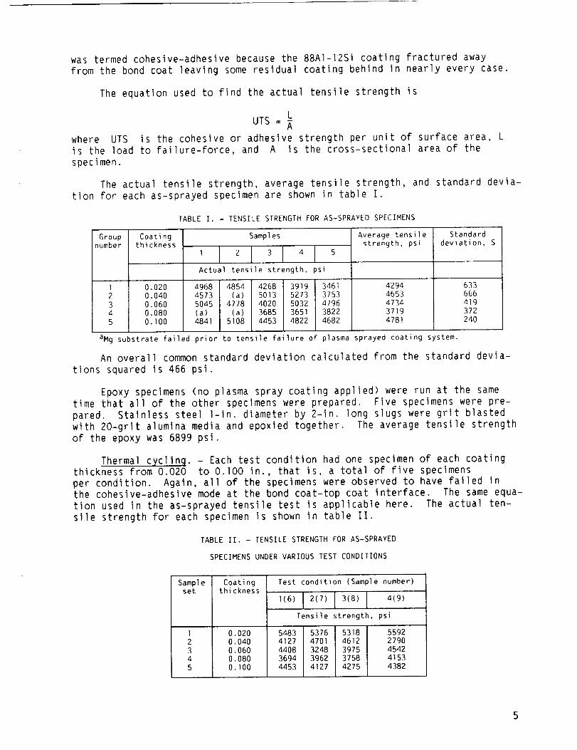
was termed cohesive-adhesive because the 88AI-12Si coating fractured awayfrom the bond coat leaving someresidual coating behind in nearly every case.
The equation used to find the actual tensile strength is
LUTS= -A
where UTS is the cohesive or adhesive strength per unit of surface area, Lis the load to failure-force, and A is the cross-sectional area of the
specimen.
The actual tensile strength, average tensile strength, and standard devia-tion for each as-sprayed specimen are shown in table I.
TABLE I. - TENSILE STRENGTH FOR AS-SPRAYED SPECIMENS
Group Coatingnumber thickness
1 0.0202 0.0403 0.0604 0.0805 O. I00
Samples
Actual tensile strength, psi
4968 4854 4268 3919 34614573 (a) 5013 5273 37535045 4778 4020 5032 4796
(a) (a) 3685 3651 38224841 5108 4453 4822 4682
Average tensilestrength, psi
42944653473437194781
Standarddeviation, S
633666419372240
aMg substrate failed prior to tensile failure of plasma sprayed coating system.
An overall common standard deviation calculated from the standard devia-
tions squared is 466 psi.
Epoxy specimens (no plasma spray coating applied) were run at the sametime that all of the other specimens were prepared. Five specimens were pre-pared. Stainless steel l-in. diameter by 2-in. long slugs were grit blastedwith 20-grit alumina media and epoxied together. The average tensile strengthof the epoxy was 6899 psi.
Thermal cycling. - Each test condition had one specimen of each coatingthickness from 0.020 to 0.]00 in., that is, a total of five specimens
per condition. Again, all of the specimens were observed to have failed inthe cohesive-adhesive mode at the bond coat-top coat interface. The same equa-
tion used in the as-sprayed tensile test is applicable here. The actual ten-
sile strength for each specimen is shown in table II.
TABLE II. - TENSILE STRENGTH FOR AS-SPRAYED
SPECIMENS UNDER VARIOUS TEST CONDITIONS
Sample Coatingset thickness
I 0.0202 0.0403 0.0604 0.0805 0.I00
Test condition (Sample number)
i(6) 1 2(7) I 3(8) I 4(9)
Tensile strength, psi
5483 5376 5318 55924127 4701 4612 27904408 3248 3975 45423694 3962 3758 41534453 4127 4275 4382
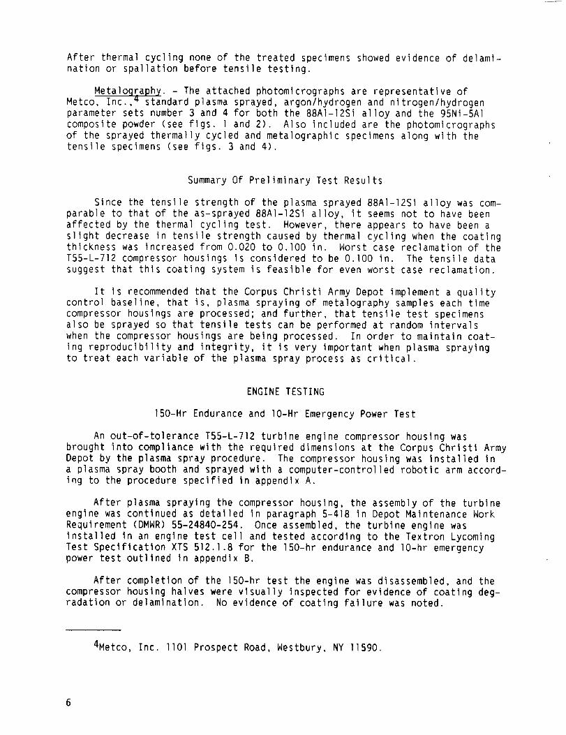
After thermal cycling none of the treated specimens showed evidence of delami-nation or spallation before tensile testing.
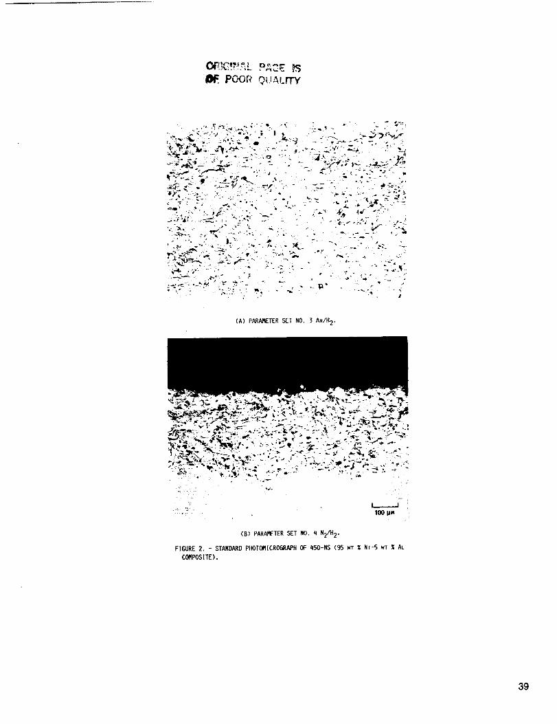
MetaloQraphy. - The attached photomicrographs are representative of
Metco, Inc., 4 standard plasma sprayed, argon/hydrogen and nitrogen/hydrogen
parameter sets number 3 and 4 for both the 88Al-12Si alloy and the 95Ni-5Al
composite powder (see figs. l and 2). Also included are the photomicrographs
of the sprayed thermally cycled and metalographic specimens along with the
tensile specimens (see figs. 3 and 4).
Summary Of Preliminary Test Results
Since the tensile strength of the plasma sprayed 88AI-12Si alloy was com-
parable to that of the as-sprayed 88AI-12Si alloy, it seems not to have been
affected by the thermal cycling test. However, there appears to have been a
slight decrease in tensile strength caused by thermal cycling when the coatingthickness was increased from 0.020 to O.lO0 in. Worst case reclamation of the
T55-L-712 compressor housings is considered to be O.lO0 in. The tensile data
suggest that this coating system is feasible for even worst case reclamation.
It is recommended that the Corpus Christi Army Depot implement a qualitycontrol baseline, that is, plasma spraying of metalography samples each time
compressor houslngs are processed; and further, that tensile test specimens
also be sprayed so that tensile tests can be performed at random intervals
when the compressor housings are being processed. In order to maintain coat-
ing reproducibility and integrity, it is very important when plasma spraying
to treat each variable of the plasma spray process as critical.
ENGINE TESTING
150-Hr Endurance and lO-Hr Emergency Power Test
An out-of-tolerance T55-L-712 turbine engine compressor housing wasbrought into compliance with the required dimensions at the Corpus Christi ArmyDepot by the plasma spray procedure. The compressor housing was installed ina plasma spray booth and sprayed with a computer-controlled robotic arm accord-ing to the procedure specified in appendix A.
After plasma spraying the compressor housing, the assembly of the turbine
engine was continued as detalled in paragraph 5-418 in Depot Maintenance Work
Requirement (DMWR) 55-24840-254. Once assembled, the turbine engine was
installed In an engine test cell and tested according to the Textron Lycoming
Test Speclflcatlon XTS 512.1.8 for the 150-hr endurance and lO-hr emergencypower test outlined in appendix B.
After completion of the 150-hr test the engine was disassembled, and the
compressor housing halves were visually inspected for evidence of coating deg-radation or delamination. No evidence of coating failure was noted.
4Metco, Inc. llOl Prospect Road, Westbury, NY 11590.
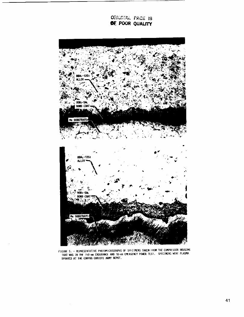
After completion of the visual inspection, one of the compressor housinghalves was shipped to the U.S. Army Propulsion Directorate at NASALewisResearch Center where it was processed into samples for metalographic inspec-tion according to the procedure specified in the section Metalography. Theresults of the metalographic inspection (see fig. 5) revealed no significantdefects that could not have been prevented by following the procedure speci-fied in appendix A, and by implementing the quality control baseline recom-mendedin the section Summaryof Preliminary Test Results.
200-Hour Flight Test
An out-of-tolerance TS5-L-712 turbine engine compressor housing wasbrought into compliance with the required dimensions at Corpus Christi ArmyDepot by the plasma spray procedure. The compressor housing was installed ina plasma spray booth and sprayed with a computer-controlled robotic arm accord-ing to the procedure specified in appendix A.
After plasma spraying the compressor housing, the assembly of the turbineengine, in conjunction with a modified engine torque indicating system, wascontinued as described in paragraph 5-418 in DMNR55-2840-254. The engine wasflown for a 200-hr flight test by the U.S. Army Aviation Development TestActivity, Fort Rucker, AL, under the direction of the U.S. Army Test and Evalu-ation Commandat the request of the CH47Modernization Project Manager. Theflight test consisted of numeroustakeoffs, landings, hovering maneuvers, andflight demonstrations during which the engine was operated at a variety ofloads, speeds, and torques.
After completion of the 200-hr test the engine was disassembled, and thecompressor housing halves were visually inspected for evidence of coating deg-radation or delamination. No evidence of coating failure was noted.
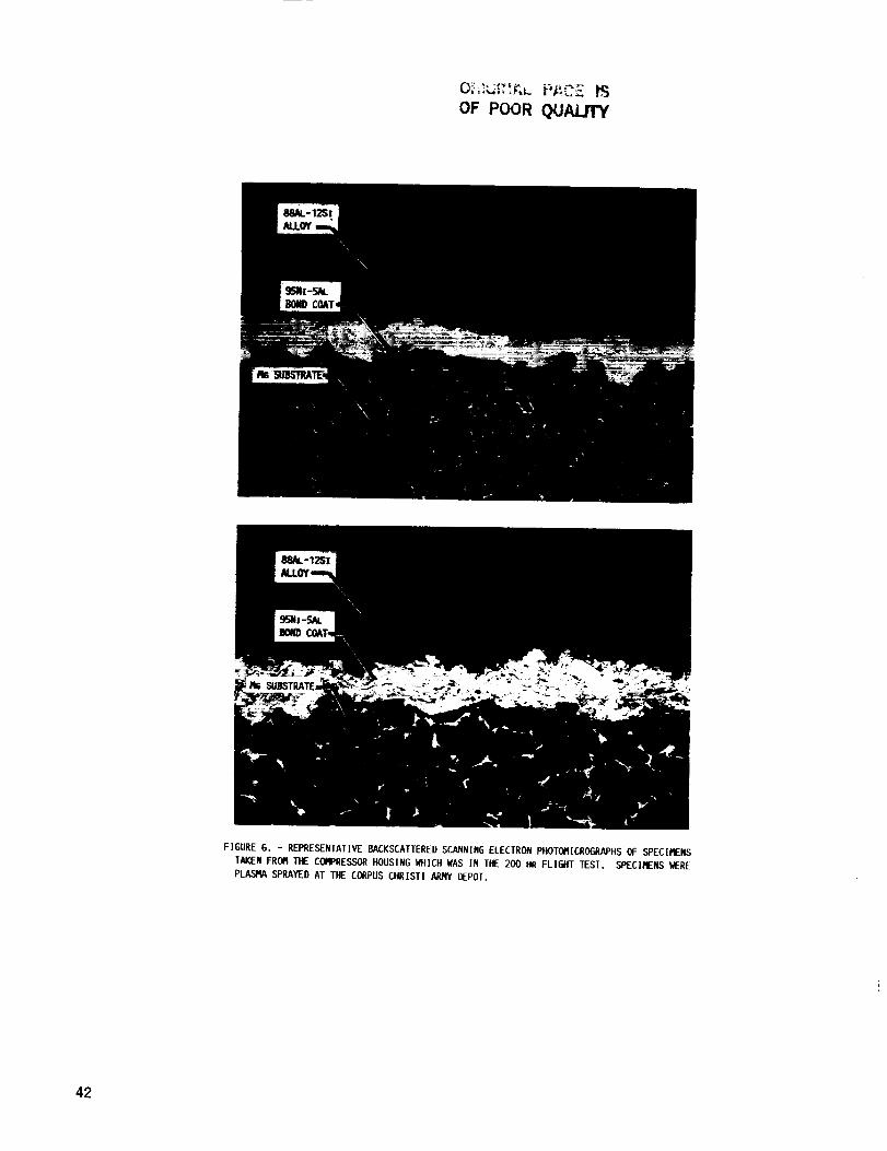
After completion of the visual inspection, one of the compressor housinghalves was shipped to the U.S. Army Propulsion Directorate at NASALewisResearchCenter where it was processed into samples for metalographic inspec-tion according to the procedure specified in the section Metalography. Theresults of the metalographic inspection (fig. 5) revealed no significantdefects that could not have been prevented by following the procedure speci-fied in appendix A and by implementing the quality control baseline recom-mendedin this report (see Summaryof Preliminary Test Results). Refer tophotographs in figure 6.
SummaryOf Engine Test Results
The metalographic inspections revealed that the plasma sprayed 88AI-12Sicoating was affected by neither the 150-hr engine test nor the 2OO-hr flighttest. These inspections showedthat the plasma sprayed coating system is fea-sible for reclaiming out-of-tolerance T55-L-712 turbine engine compressorhousings.
CONCLUSIONS
The thermally-cycled, tensile-tested specimens met the author's minimumtensile strength requirements. The metalographic specimens from the 150-hr
engine and 200-hr flight tests revealed no significant defect that could not
have been eliminated by following the procedures specified herein. Therefore,the following recommendations are made:
I. The application of 88 wt % aluminum-12 wt % s111con a11oy by a plasmaspray process should be incorporated Into the overhaul procedure to reclaim
out-of-tolerance T55-L-712 turbine engine compressor housings.
2. The Corpus Chrlsti Army Depot should implement a quality control base-
line; that is, plasma spraying of metalography samples each t_me compressorhousings are processed.
3. Tensile-test specimens should also be sprayed in order that tensile
tests may be performed at random intervals when the compressor housings arebeing processed.
4. These tensile-test samples should have a minimum tensile strength of3000 psi.
It is especially important to note that in order to ensure coating repro-ducibility and integrity each variable of the plasma spray process (such asmaintaining kilowatts, spray distance, spray rates, primary and secondary gasflows, and traverse speeds) must be treated as critical.
ACKNOWLEDGMENT
The U.S. Army AVSCOM wishes to acknowledge the contributions of thefollowing inidividuals: Carl Stearns of the NASA Lewis Environmental
Durability Branch, who provided the services of George Leissler, SverdrupTechnology, Inc.; Robert Davles and the NASA Lewis Analytical Science Branch,
who provided metalographic analyses of the samples; and Joseph Certo of the
AVSCOM Propulsion Directorate, who processed and expedlted the close-out phaseof this project.
Appendix A
T55-L-712 COMPRESSORHOUSINGREFURBISHMENTPROCEDURE
Carl ReitenbachPropulsion Directorate
U.S. Army Aviation Research and Technology Activity - AVSCOMLewis ResearchCenterCleveland, Ohio 44135
INTRODUCTION
These procedures describe the requirements and preparations for reclaimingcompressor housings utilizing a plasma spray process.
REFERENCEDOCUMENT
The following procedure has been structured from the Depot MaintenanceHork Requirements (DMWRNo. 55-2840-254) dated 28 September 1984, a PlasmaSpray Procedure developed specifically for use with Metco, Inc., equipment byGeorge N. Leissler, Engineering Associate V., Sverdrup Technology Incorporated,and process refinements developed during specimen testing by George Gilchristand Cliff Darling of the Production Engineering Department at Corpus ChristiArmy Depot.
NOTE
Due to possible variations in the DMWRprocedures versus actual modifiedprocedures used by depot personnel, revisions to this procedure to interfacewith current work requirements are permitted. These revised steps must be doc-umentedand approved by the appropriate authority.
COMPRESSORHOUSINGREFURBISHMENTPROCEDURE
INTRODUCTION
To begin thls process reference section XIV of DMWR 55-2840-254, page5-774.
Perform disassembly of compressor housing and vane assembly asdescribed in paragraph 5-414 and complete steps a. through m.
Perform cleaning of compressor housing and vane assembly asdescribed in paragraph 5-415.
Perform inspection of compressor housing and vane assembly asdescribed in paragraph 5-416.
5-417. REPAIR OF COMPRESSOR HOUSING AND VANE ASSEMBLY.
Replace step e. with the following procedure.
e. Housing assembly (compressor) (9g, figure 5-311).
(l). Perform removal of Engine Gray Ename] using steps g.Method B. items (la), (Ib), or (Ic). (Reference SP No.6022 in appendix D, DMWR 55-2840-254).
(2). Vapor degrease compressor housing using Trichloroethane(item 252 in appendix C, DMWR55-2840-254 or equal).
(3). Ensure removal of all residue from the compressorhousing uslng clean dry air.
(4). Perform step e. items (1), (3a), and (3b) in DMWR55-2840-254, paragraph 5-417.
(5). Perform step e. items (4a) and (4b) in DMWR55-2840-254,paragraph 5-4]7.
(6). Perform step e. items (6a through 6f) in DMWR55-2840-254, paragraph 5-417.
(7). Perform step e. item (7a) and (7b) in DMWR 55-2840-254,paragraph 5-417.
10
5-417 (cont.)
REFERENCE ITEM (8) IN DMWR55-2840-254 AND REPLACE OR INSERT THE FOLLOWINGSTEPS AS INDICATED
(8). Repair compressor housing to restore dimensions by
plasma spray method as follows:
PREMACHINING:
NOTE:
ENSURE THAT COMPRESSORHOUSING CASE HALVES HAVE MATCHING SERIAL NUMBERS.
(a). Place housing assemblies (99, figure 5-311) in asuitable locating fixture and center on a verticalturret lathe or equivalent.
(b). Position contour gage template assembly LTCTI1420,
or equivalent, in trace section of vertical turretlathe.
(c). Bring cutting tool into contact with housing
assembly at location A (see figure 5-319) and bring
tracer stylus into contact with template at
corresponding location.
(d). Raise tracer, as necessary, to machine contour toobtain a .017 inch minimum plasma spray buildupthickness after final machining and painting. Upto .050 inch maximum thickness is permissible.Check contour with gage LTCTII421 or equivalent.Cleanup as required from location A to O, figure5-319.
(e). The following areas of the compressor housingrequiring restoration must also be machined toobtain a .017 minimum plasma spray buildupthickness after final machining. (Reference figure5-318 for final dimensional specifications andlocations.)
I. Compressor housing I.D. in vane assembly andinsert mounting area.
2. Compressor housing pilot diameters A and K.
3. Compressor housing end to end face surfacedimensions (refer to 12.512112.502 dimension
in figure 5-318).
(f). Treat all machined surfaces with chromic acidsolution (item 226 in appendix C, DMWR55-2840-254).
II
5-417 (cont.)
(g). Clean housing assembly by vapor degreasing method(reference SP No. 3000 in appendix D, DMWR55-2840-254).
PLASMASPRAYCONSOLESETTINGS"
(a). Set the following parameters forapplication of the 450-NSbond coat.
* Arc amps. - 500 + I0* Arc volts - 67 + 3* Use wheel type* Kilowatt output - up to 40 kW* Set turntable speed to I00 rpm
(b). Set the primary and secondary gas pressures andflows, with the exhaust system on, as fo]]ows"
I. Set the primary gas pressure at 100 psi.(ARGON)
2. Set the primary flow at 80 CFM,
3. Set the secondary gas pressure at 50 psi.(HYDROGEN)
EXTREME CAUTION:
THE SECONDARY GAS FLOW VALVE MUST REMAIN CLOSEDUNTIL THE HIGH FREQUENCY IGNITION OCCURS AND THEPLASMA SPRAY GUN IS AT FULL OPERATION. FAILURE TOFOLLOW THIS PROCESS WILL RESULT IN GUN FAILURE OREXPLOSION.
4. Slowly introduce secondary gas flow whilemaintaining machine amperage, and set at15 ± 5 CFM, to achieve operating voltage,
(c). Set the carrier gas flow at 37 CFM.
(d). Set the spray rate at 9 pounds perhour ± 1 pound per hour.
I. Set the powder feed (using powder portnumber 2) for the spray gun as follows"
* Ensure the carrier gas flow has been set.
Weigh a clean dry container sufficient tohold 2.5 Ibs. of Metco 450-NS powder (item 5attachment A.
12
5-417 (cont.)
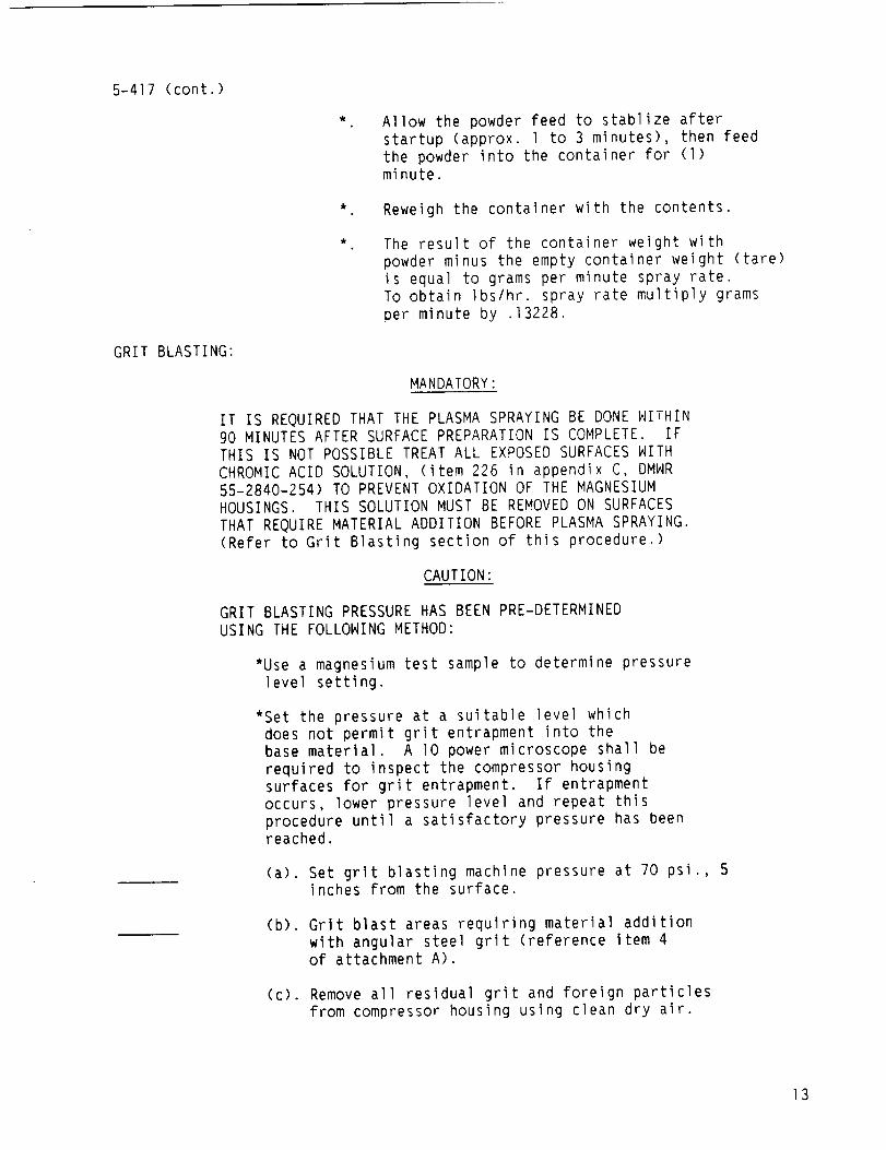
GRIT BLASTING:
Allow the powder feed to stablize afterstartup (approx. 1 to 3 minutes), then feedthe powder into the container for (l)minute.
Reweigh the container with the contents.
The result of the container weight with
powder minus the empty container weight (tare)is equal to grams per minute spray rate.
To obtain Ibs/hr. spray rate multiply grams
per minute by .13228.
MANDATORY:
IT IS REQUIRED THAT THE PLASMA SPRAYING BE DONE WITHIN90 MINUTES AFTER SURFACE PREPARATION IS COMPLETE. IFTHIS IS NOT POSSIBLE TREAT ALL EXPOSED SURFACES WITHCHROMIC ACID SOLUTION, (item 226 in appendix C, DMWR55-2840-254) TO PREVENT OXIDATION OF THE MAGNESIUMHOUSINGS. THIS SOLUTION MUST BE REMOVED ON SURFACESTHAT REQUIRE MATERIAL ADDITION BEFORE PLASMA SPRAYING.(Refer to Grit Blasting section of this procedure.)
CAUTION:
GRIT BLASTING PRESSURE HAS BEEN PRE-DETERMINEDUSING THE FOLLOWING METHOD:
*Use a magnesium test sample to determine pressurelevel setting.
*Set the pressure at a suitable level whichdoes not permit grit entrapment into thebase material. A I0 power microscope shall berequired to inspect the compressor housingsurfaces for grit entrapment. If entrapmentoccurs, lower pressure level and repeat thisprocedure until a satisfactory pressure has beenreached.
(a). Set grit blasting machine pressure at 70 psi., 5inches from the surface.
(b). Grit blast areas requiring material addition
with angular steel grit (reference item 4of attachment A).
(c). Remove all residual grit and foreign particlesfrom compressor housing using clean dry air.
13
5-417 (cont.)
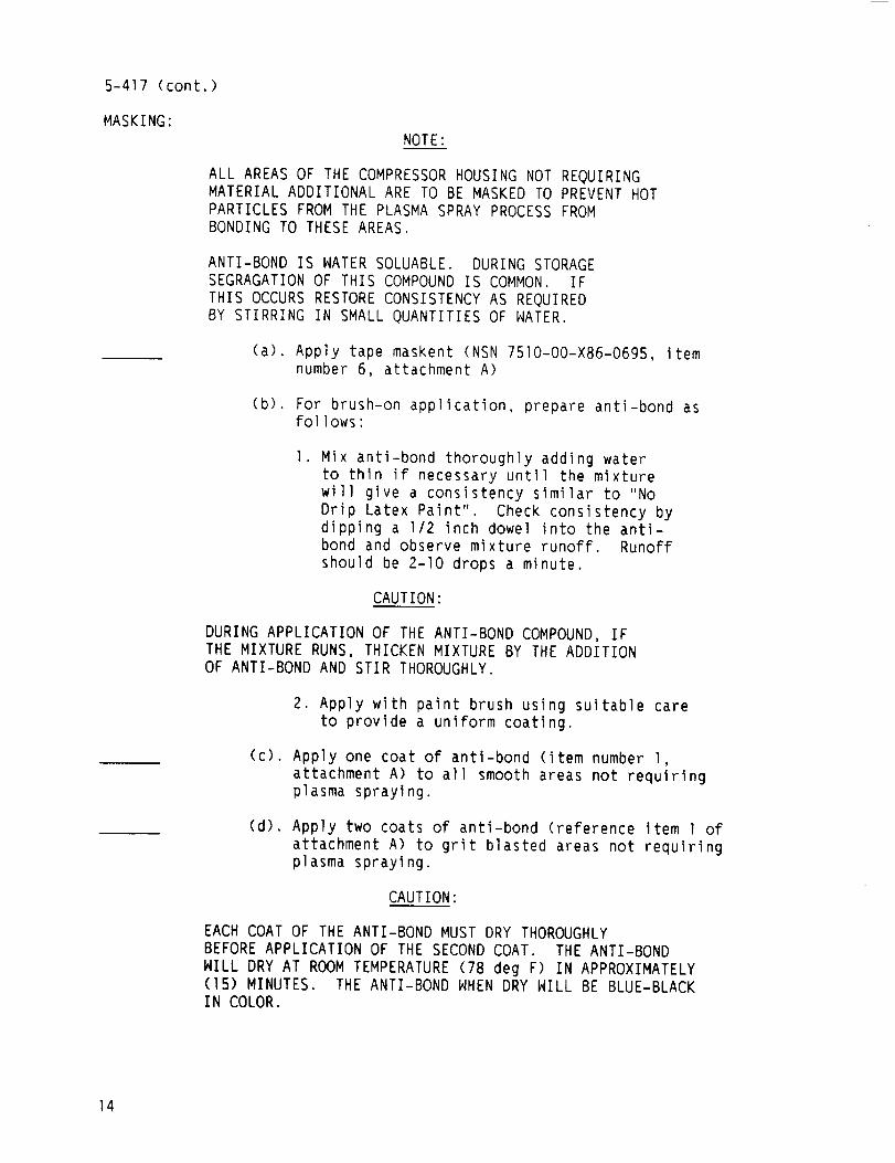
MASKING:NOTE:
ALL AREASOF THECOMPRESSORHOUSINGNOTREQUIRINGMATERIALADDITIONALARETOBEMASKEDTOPREVENTHOTPARTICLESFROMTHEPLASMASPRAYPROCESSFROMBONDINGTOTHESEAREAS.
ANTI-BONDIS WATERSOLUABLE.DURINGSTORAGESEGRAGATIONOF THISCOMPOUNDIS COMMON.IFTHIS OCCURSRESTORECONSISTENCYAS REQUIREDBY STIRRINGIN SMALLQUANTITIESOFWATER.
(a). Apply tape maskent (NSN7510-00-X86-0695, itemnumber6, attachment A)
(b). For brush-on application, prepare anti-bond asfollows:
]. Mix anti-bond thoroughly adding waterto thin if necessary until the mixturewill give a consistency similar to "NoDrip Latex Paint". Check consistency bydipping a 1/2 inch dowel into the anti-bond and observe mixture runoff. Runoffshould be 2-10 drops a minute.
CAUTION:
DURING APPLICATION OF THE ANTI-BOND COMPOUND, IFTHE MIXTURE RUNS, THICKEN MIXTURE BY THE ADDITIONOF ANTI-BOND AND STIR THOROUGHLY.
2. Apply with paint brush using suitable careto provide a uniform coating.
(c). Apply one coat of anti-bond (item number 1,attachment A) to all smooth areas not requiringplasma spraying.
(d). Apply two coats of anti-bond (reference Item 1 ofattachment A) to grit blasted areas not requiringplasma spraying.
CAUTION:
EACH COAT OF THE ANTI-BOND MUST DRY THOROUGHLY
BEFORE APPLICATION OF THE SECOND COAT. THE ANTI-BOND
WILL DRY AT ROOM TEMPERATURE (78 deg F) IN APPROXIMATELY(15) MINUTES. THE ANTI-BOND WHEN DRY WILL BE BLUE-BLACKIN COLOR.
14
5-417 (cont.)
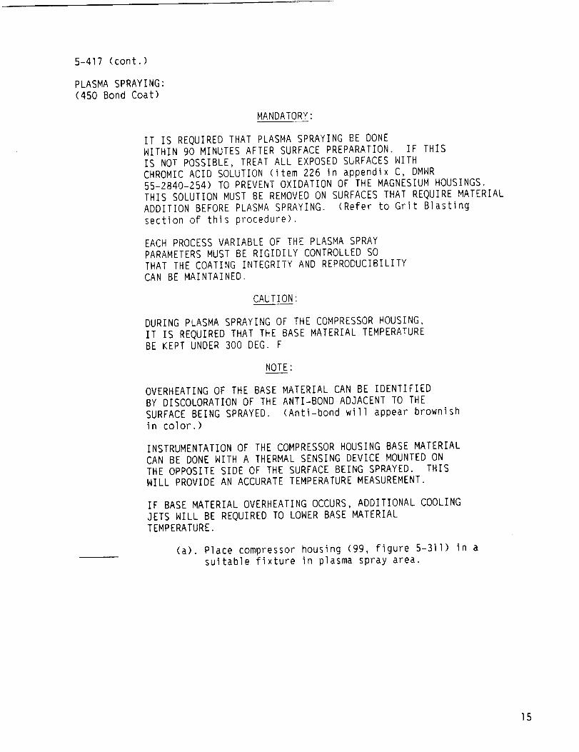
PLASMA SPRAYING:(450 Bond Coat)
MANDATORY:
IT IS REQUIRED THAT PLASMA SPRAYING BE DONEWITHIN 90 MINUTES AFTER SURFACE PREPARATION. IF THISIS NOT POSSIBLE, TREAT ALL EXPOSED SURFACES WITHCHROMIC ACID SOLUTION (item 226 in appendix C, DMWR55-2840-254) TO PREVENT OXIDATION OF THE MAGNESIUM HOUSINGS.THIS SOLUTION MUST BE REMOVED ON SURFACES THAT REQUIRE MATERIALADDITION BEFORE PLASMA SPRAYING. (Refer to Grit Blastingsection of this procedure).
EACH PROCESS VARIABLE OF THE PLASMA SPRAYPARAMETERS MUST BE RIGIDILY CONTROLLED SOTHAT THE COATING INTEGRITY AND REPRODUCIBILITYCAN BE MAINTAINED.
CAUTION:
DURING PLASMA SPRAYING OF THE COMPRESSORHOUSING,IT IS REQUIRED THAT THE BASE MATERIAL TEMPERATUREBE KEPT UNDER 300 DEG. F
NOTE:
OVERHEATING OF THE BASE MATERIAL CAN BE IDENTIFIEDBY DISCOLORATION OF THE ANTI-BOND ADJACENT TO THESURFACE BEING SPRAYED. (Anti-bond will appear brownishin color.)
INSTRUMENTATION OF THE COMPRESSORHOUSING BASE MATERIALCAN BE DONE WITH A THERMAL SENSING DEVICE MOUNTED ONTHE OPPOSITE SIDE OF THE SURFACE BEING SPRAYED. THISWILL PROVIDE AN ACCURATE TEMPERATURE MEASUREMENT.
IF BASE MATERIAL OVERHEATING OCCURS, ADDITIONAL COOLINGJETS WILL BE REQUIRED TO LOWER BASE MATERIALTEMPERATURE.
(a). Place compressor housing (99, figure 5-311) in asuitable fixture in plasma spray area.
15
5-417 (cont.)
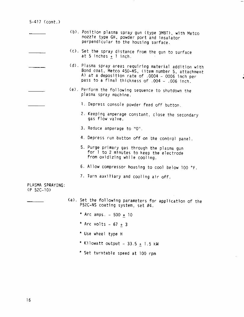
PLASMASPRAYING:(P 52C-I0)
(b). Position plasma spray gun (type 3MBT), with Metconozzle type GH, powder port and insulatorperpendicular to the housing surface.
(c). Set the spray distance from the gun to surfaceat 5 inches + I inch.
(d). Plasma spray areas requiring material addition withBond coat, Metco 450-NS, (item number5, attachmentA) at a deposition rate of .0004 - 0006 inch perpass to a final thickness of .004 - .006 inch.
(e). Perform the following sequence to shutdown theplasma spray machine.
I. Depress console powder feed off button.
2. Keeping amperageconstant, close the secondarygas flow valve.
3. Reduceamperageto "0"
4. Depress run button off on the control panel.
5. Purge primary gas through the plasma gunfor 1 to 2 minutes to keep the electrodefrom oxidizing while cooling.
6. Allow compressor housing to cool below I00 °F.
7. Turn auxiliary and cooling air off.
(a). Set the following parameters for application of theP52C-NS coating system, set #4.
* Arc amps. - 500 + I0
* Arc volts - 67 + 31
* Use wheel type H
* Kilowatt output - 33.5 + 1.5 kW
* Set turntable speed at I00 rpm
16

5-4]7 (cont.)
(b). Set the primary and secondary gas pressures andflows, with the exhaust system on, as follows"
I. Set the primary gas pressure at I00 psi.(ARGONGAS)
2. Set the secondary gas pressure at 50 psi.(HYDROGENGAS)
3. Set the primary flow at 80 CFM.
EXTREME CAUTION:
THE SECONDARY GAS FLOW VALVE MUST REMAIN CLOSEDUNTIL THE HIGH FREQUENCY IGNITION OCCURS AND THEPLASMA SPRAY GUN IS AT FULL OPERATION. FAILURE TOFOLLOW THIS PROCESS WILL RESULT IN GUN FAILUREOR EXPLOSION.
4. Slowly introduce secondary gas flow whilemaintaining machine amperage, and set at 15.
(c). Set the carrier gas flow at 37 CFM.
(d). Set the spray rate at lO pounds per hour ± 1 poundper hour.
I. Set the powder feed (using powder port #l) forthe spray gun as follows"
* Ensure the carrier gas flow has been set.
Weigh a clean dry container sufficient tohold 2.5 Ibs. of Metco P 52C-NS powder (item 3of attachment A).
Allow the powder feed to stablize afterstartup (approx. I to 3 minutes), then feedthe powder into the container for (I)minute.
* Reweigh the container with the contents.
The result of the container weight withpowder minus the empty container weight (tare)is equal to grams per minute spray rate.To obtain Ibs/hr. spray rate multiply gramsper minute by .13228.
17
5-4]7 (cont.)
(e). Set the spray distance from the gun to the surfaceat 5 inches + 1 inch.
(f). Plasma spray areas requiring material addition with
Metco 52C-NS at a deposition rate of .004 - .006 inch
per pass to a finished coating thickness of .015 to .020inch oversized from the desired final dimensions.
(Maximum coating thickness should not exceed .050).
CAUTION:
DURING PLASMA SPRAY OF THE COMPRESSOR HOUSING,IT IS REQUIRED THAT THE BASE MATERIAL TEMPERATUREBE KEPT UNDER 300 DEG. F
NOTE:
OVERHEATING OF THE BASE MATERIAL CAN BE IDENTIFIEDBY DISCOLORATION OF THE ANTI-BOND ADJACENT TO THESURFACE BEING SPRAYED. (Anti-bond will appear brownish%n color.)
INSTRUMENTATION OF THE COMPRESSOR HOUSING BASE MATERIALCAN BE DONE WITH A THERMAL SENSING DEVICE MOUNTED ONTHE OPPOSITE SIDE OF THE SURFACE BEING SPRAYED. THISWILL PROVIDE AN ACCURATE TEMPERATURE MEASUREMENT.
IF BASE MATERIAL OVERHEATING OCCURS, ADDITIONAL COOLINGJETS WILL BE REQUIRED TO LONER BASE MATERIAL TEMPERATURE.
(g). Perform the following sequence to shutdown theplasma spray machine:
I. Depress console powder feed off button.
2. Keeping amperage constant, close the secondarygas flow valve.
3. Reduce amperage to "0".
4. Depress run button off on the control panel.
5. Purge primary gas through the plasma gunfor I to 2 minutes to keep the electrodefrom oxidizing while cooling.
6. Turn spray gun off.
7. Allow housing to cooi below I00 °F.
8. Turn auxiliary and cooling air off.
18
5-417 (cont.)
9. Removecompressor housing from plasma sprayarea.
ANTI-BONDREMOVAL:
CAUTION:
DO NOT USE SOLVENTS OR DEGREASING AGENTS TO REMOVEANTI-BOND.
(a). Remove tape type masking.
(b). Remove anti-bond with a suitable wire brush.
(c). Remove heavy overspray from material addition with asuitable wire brush.
POST MACHINING:
(a). File excess plasma spray material from compressorhousing splitline to obtain sharp, square corners.
(b). Remove excess plasma spray material from thethrough holes in the compressor housing using asuitable reamer.
(c). Remove loose particles from the compressorhousing with clean dry compressed air.
(d). Seal all plasma sprayed areas with Coriconesealer. (item 2 attachment A)
CAUTION:
DURING FINAL MACHINING ENSURE THAT THE COATINGHAS NOT SEPARATED FROM THE BASE MATERIAL. (PULLOUT)IF PULLOUT IS EVIDENT ENSURE THAT THE MACHININGPARAMETERS USED, (ie., dull tool bits, excessivematerial removal, etc...) WERE NOT AT FAULT.
CAUTION:
FINAL MACHINED DIMENSIONS MUST INCLUDE A TOLERANACE FORAPPLICATION OF .001 to .002 SYNTHETESINE PAINT.(reference DMWR55-2840-254, item 242 in appendix C)
(a). Final machine compressor housing areas that havebeen plasma sprayed to dimensions shown in DMWR(reference figure 5-318) as listed:
I. Machine centrifugal land area using locationA and location 0 (figure 5-319) as contourgage points. Final check with contour gage orequivalent.
19
5-417 (cont.)2. Compressorhousing I.D. in vane assembly and insert
mounting and area.
3. Compressorhousing pilot diameters A,B,C,D, ANDK.
4. Compressorhousing end to end face surface.
(b). Redefine housing as having aluminum sprayed surfaces byadding an (-(_)) after housing serial number.
CORROSIONPREVENTION:
(a). Treat all reworked aluminum surfaces with alodinesolution (reference DMWR55-2840-254, item 14 inappendix C), reworked magnesiumsurfaces withchromic pickle solution (reference DMNR55-2840-254, item 226 in appendix C).
CONTINUEPROCESSOFCOMPRESSORHOUSINGANDVANEASSEMBLYREASSEMBLYPERPARAGRAPH5-417 in DMWR55-2840-254.
2O
ITEMNO. DESCRIPTION
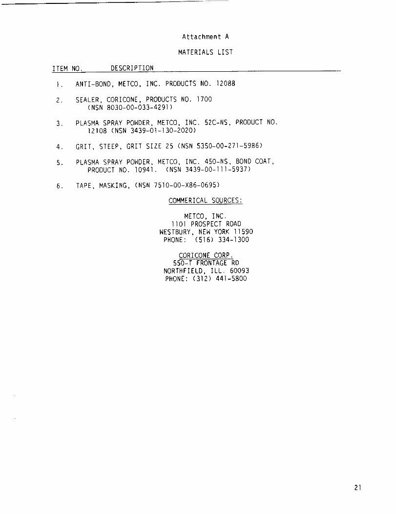
Attachment A
MATERIALSLIST
°
2.
°
,
5.
,
ANTI-BOND, METCO, INC. PRODUCTS NO. 12088
SEALER, CORICONE, PRODUCTS NO. 1700(NSN 8030-00-033-4291)
PLASMA SPRAY POWDER, METCO, INC. 52C-NS, PRODUCT NO.12108 (NSN 3439-01-130-2020)
GRIT, STEEP, GRIT SIZE 25 (NSN 5350-00-271-5986)
PLASMA SPRAY POWDER, METCO, INC. 450-NS, BOND COAT,PRODUCT NO. 10941. (NSN 3439-00-111-5937)
TAPE, MASKING, (NSN 7510-00-×86-0695)
COMMERICAL SOURCES:
METCO, INC.II01 PROSPECT ROAD
WESTBURY, NEW YORK 11590PHONE: (516) 334-1300
CORICONE CORP.550-T FRONTAGE RD
NORTHFIELD, ILL. 60093PHONE: (312) 441-5800
21
APPENDIX B
AVCO LYCOMING TEST SPECIFICATION
XTS 512.1.8
150-HOUR ENDURANCE AND tO-HOUR EMERGENCY POWER TEST
T55-L-712
Prepared By:°-' •
,I. KoZ_I_ -
T55 Test Engineer
Approved By:
away /
Manager (Dev.)Engine Test
Aircraft Turboshaft
22
May 1986
Test Specification XTS 512.1.8
Page 1
.
°
.
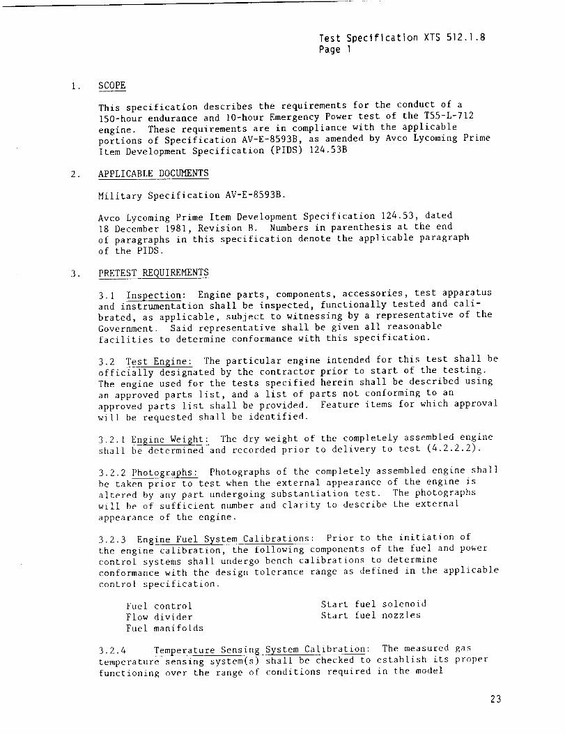
SCOPE
This specification describes the requirements for the conduct of a
150-hour endurance and lO-hour Emergency Power test of the T55-L-712
engine. These requirements are in compliance with the applicable
portions of Specification AV-E-8593B, as amended by Avco Lycoming Prime
Item Development Specification (PIDS) 124.53B
APPLICABLE DOCUMENTS
Military Specification AV-E-8593B.
Avco Lycoming Prime Item Development Specification 124.53, dated
18 December 1981, Revision B. Numbers in parenthesis at the end
of paragraphs in this specification denote the applicable paragraph
of the PIDS.
PRETEST REQUIREMENTS
3.1 Inspection: Engine parts, components, accessories, test apparatusand instrumentation shall be inspected, functionally tested and cali-
brated, as applicable, subject to witnessing by a representative of the
Government. Said representative shall be given all reasonable
facilities to determine conformance with this specification.
3.2 Test Engine: The particular engine intended for this test shall be
officially designated by the contractor prior to start of the testing.
The engine used for the tests specified herein shall be described using
an approved parts list, and a list of parts not conforming to an
approved parts list shall be provided. Feature items for which approval
will be requested shall be identified.
3.2.1 Engine Weight: The dry weight of the completely assembled engineshall be determined and recorded prior to delivery to test (4.2.2.2).
3.2.2 Photographs: Photographs of the completely assembled engine shall
be taken prior to test when the external appearance of the engine is
altered by any part undergoing substantiation test. The photographs
will be of sufficient number and clarity to describe the external
appearance of the engine.
3.2.3 Engine Fuel System Calibrations: Prior to the initiation of
the engine calibration, the following components of the fuel and power
control systems shall undergo bench calibrations to determine
conformance with the design tolerance range as defined in the applicable
control specification.
Fuel control
Flow divider
Fuel manifolds
Start fuel solenoid
Start fuel nozzles
3.2.4 Temperature Sensing System Calibration: The measured gas
temperature sensing system(s) shall be checked to establish its proper
functioning over the range of conditions required in the model
23
Test Specification XTS 512.1.8Page 2
.
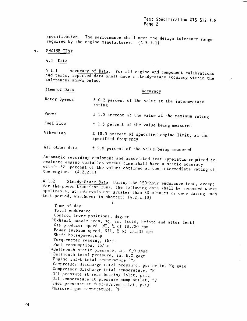
specification. The performance shall meet the design tolerance rangerequired by the engine manufacturer. (4.5.1.1)
ENGINE TEST
4.1 Data
4.1.1 Accuracy of Data: For all engine and component calibrations
and tests, reported data shall have a steady-state accuracy within thetolerances shown below.
Item of Data
Rotor Speeds
Accurac_
± 0.2 percent of the value at the intermediaterating
Power
Fuel Flow
Vibration
All other data
± 1.0 percent of the value at the maximum rating
± 1.5 percent of the value being measured
± I0.0 percent of specified engine limit, at the
specified frequency
± 2.0 percent of the value being measured
Automatic recording equipment and associated test apparatus required to
evaluate engine variables versus time shall have a static accuracy
within ±2 percent of the values obtained at the intermediate rating ofthe engine. (4.2.2.1)
4.1.2 Steady-State Data During the 150-hour endurance test, except
for the power transient runs, the following data shall be recorded where
applicable, at intervals not greater than 30 minutes or once during eachtest period, whichever is shorter: (4.2.2.10)
Time of dayTotal endurance
Control lever positions, degrees
*Exhaust nozzle area, sq. in. (cold, before and after test)
Gas producer speed, NI, % of 18,720 rpm
Power turbine speed, Nil, % of 15,333 rpm
Shaft horsepower,shp
Torquemeter reading, Ib-ft
Fuel consumption, ib/hr
*Bellmouth static pressure, in. H^O gage
*Bellmouth total pressure, in. H26 gageEngine inlet total temperature, °F
Compressor discharge total pressure, psi or in. Hg gage
Compressor discharge total temperature, °F
Oil pressure at rear bearing inlet, psig
Oii temperature at pressure pump outlet, °F
Fuel pressure at fuel-system inlet, psigMeasured gas temperature, °F
24
Test Specification XTS 512.1.8
Page 3
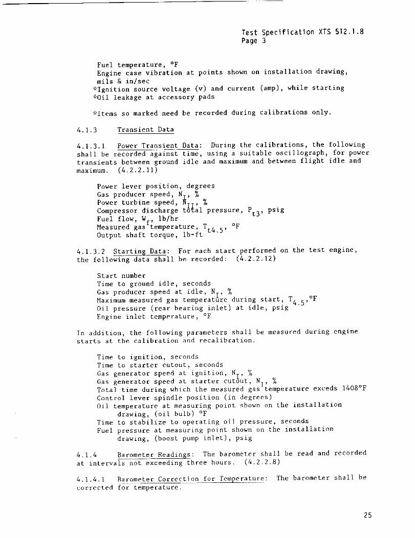
Fuel temperature, °F
Engine case vibration at points shown on installation drawing,
mils & in/sec
*Ignition source voltage (v) and current (amp), while starting
*Oil leakage at accessory pads
*Items so marked need be recorded during calibrations only.
4.1.3 Transient Data
4.1.3.1 Power Transient Data: During the calibrations, the following
shall be recorded against time, using a suitable oscillograph, for power
transients between ground idle and maximum and between flight idle and
maximum. (4.2.2.11)
Power lever position, degrees
Gas producer speed, NI, % %
_;;e_:_i_s_:_e _1 pressure, Pt3' psig
Fuel flow, W_, lb/hrMeasured gas_temperature, T.. °F
Output shaft torque, ib-ft t_.5'
4.1.3.2 Starting Data: For each start performed on the test engine,
the following data shall be recorded: (4.2.2.12)
Start number
Time to ground idle, seconds
Gas producer speed at idle, NT, % ,°FMaximum measured gas temperatfire during start, T4. 5
Oil pressure (rear bearing inlet) at idle, psig
Engine inlet temperature, °F
In addition, the following parameters shall be measured during engine
starts at the calibration and recalibration.
Time to ignition, seconds
Time to starter cutout, seconds
Gas generator speed at ignition, N , %I
Gas generator speed at starter cutout, NI, %Total time during which the measured gas temperature exceds 1408°F
Control lever spindle position (in degrees)
Oil temperature at measuring point shown on the installation
drawing, (oil bulb) °F
Time to stabilize to operating oil pressure, seconds
Fuel pressure at measuring point shown on the installation
drawing, (boost pump inlet), psig
4.1.4 Barometer Readings: The barometer shall be read and recorded
at intervals not exceeding three hours. (4.2.2.8)
4.1.4.1 Barometer Correction for Temperature: The barometer shall be
corrected for temperature.
25
Test Specification XTS 512.1.8
Page 4
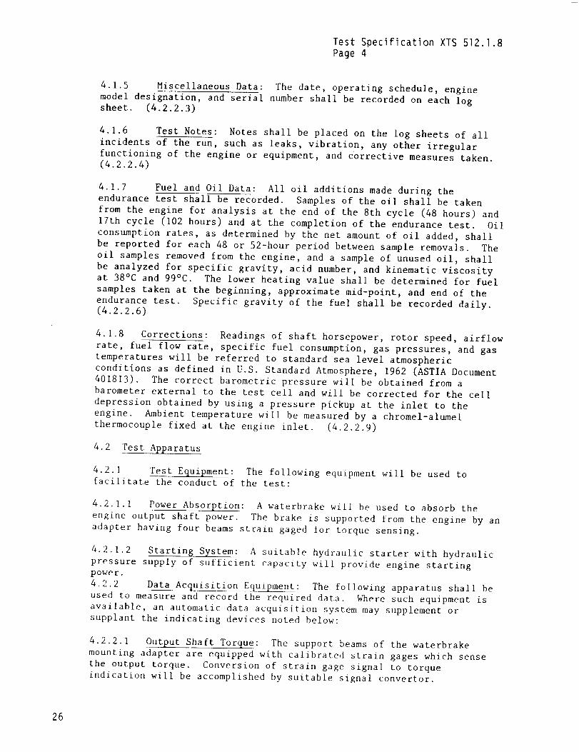
4.1.5 Miscellaneous Data: The date, operating schedule, engine
model designation, and serial number shall be recorded on each logsheet. (4.2.2.3)
4.1.6 Test Notes: Notes shall be placed on the log sheets of all
incidents of the run, such as leaks, vibration, any other irregular
functioning of the engine or equipment, and corrective measures taken.(4.2.2.4)
4.1.7 Fuel and Oil Data: All oil additions made during the
endurance test shall be recorded. Samples of the oil shall be taken
from the engine for analysis at the end of the 8th cycle (48 hours) and
17th cycle (102 hours) and at the completion of the endurance test. Oil
consumption rates, as determined by the net amount of oil added, shall
be reported for each 48 or 52-hour period between sample removals. The
oil samples removed from the engine, and a sample of unused oil, shall
be analyzed for specific gravity, acid number, and kinematic viscosity
at 38°C and 99°C. The lower heating value shall be determined for fuel
samples taken at the beginning, approximate mid-point, and end of the
endurance test. Specific gravity of the fuel shall be recorded daily.(4.2.2.6)
4.1.8 Corrections: Readings of shaft horsepower, rotor speed, airflow
rate, fuel flow rate, specific fuel consumption, gas pressures, and gas
temperatures will be referred to standard sea level atmospheric
conditions as defined in U.S. Standard Atmosphere, 1962 (ASTIA Document
401813). The correct barometric pressure will be obtained from a
barometer external to the test cell and will be corrected for the cell
depression obtained by using a pressure pickup at the inlet to the
engine. Ambient temperature will be measured by a chromel-alumel
thermocouple fixed at the engine inlet. (4.2.2.9)
4.2 'rest Apparatus
4.2.1 Test Equipment: The following equipment will be used to
facilitate the conduct of the test:
4.2.1.1 Power Absorption: A waterbrake will be used to absorb the
engine output shaft power. The brake is supported from the engine by an
adapter having four beams strain gaged for torque sensing.
4.2.1.2 Starting System: A suitable hydraulic starter with hydraulic
pressure supply of sufficient capacity will provide engine startingpower.
4.2.2 Data Acquisition Equipment: The following apparatus shall be
used to measure and record the required data. Where such equipment is
available, an automatic data acquisition system may supplement or
supplant the indicating devices noted below:
4.2.2.1 Output Shaft Torque: The support beams of the waterbrake
mounting adapter are equipped with calibrated strain gages which sense
the output torque. Conversion of strain gage signal to torque
indication will be accomplished by suitable signal convertor.
26
Test Specification XTS 512.].8
Page 5
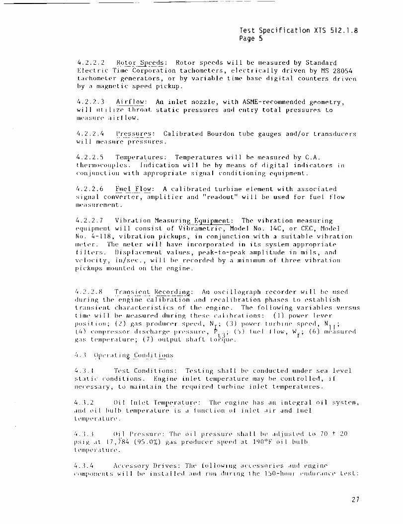
4.2.2.2 Rotor Si!.('_e___l_s: Rotor speeds will be measured by StandardElectric Time Corporation tachometers, electrically driven by MS 28054
tachometer generators, or by w]riable time base digital counters driven
hy a magnetic speed pickup.
4.2.2.3 Airflow: An inlet nozzle, with ASME-recommended geometry,
will uti l ize throat static pressures and entry total pressures tolll('dSllre ili El lOW.
4.2.2.4 Pressures: Calibrated Bourdon tube gauges and/or transducers
will measure pressures.
4.2.2.5 Tern___eeratures'. Temperatures will be measured by C.A.
thermocouples. Indication will be by means of digital indicators in
conjunction with appropriate signal conditioning equipment.
4.2.2.6 Fuel Flow: A calibrated turbine element with associated
signal converter, amplifier and "readout" will be used for fuel flowmeasurement.
4.2.2.7 V ibr_ation Measuri,lg___}{Luipment: The vibration measuringequipment will consist of Vibrametric, Model No. 14C, or CEC, Hodel
No. 4-118, vibration pickups, in conjunction with a suitable vibration
meter. The meter will have incorporated in its system appropriate
lilters. Ilisplacement values, peak-to-peak amplitude in mils, and
w'locity, in/sec., will be recorded by a minimum of three vibration
pick,ps mounted on the engine.
4.2.2.8 i(!:!ns'tj]t_tt Re_c_or___lin$: An oscillograph recorder will be used
during the engine calibration and recalibration phases to establish
transient characteristics of the engine. The following variables versustime will he measured during these calibrations: (1) power lever
position; (2) gas producer spued, N.; (3) power turbiue speed
(4) compressor discharge pressure, _t3; (5) tue[ t[ow, Wt (6i NIl;; neasure(l
gas temperature; (7) output shaft torque.
4. _ Opc,-a t i n$ Condi ti_(!ns
4.3. 1 Test Conditions: Testing shall be conducted under sea levelstat ic conditions-[- -['iti-gli{e inlet temperature may he control led, i f
necessary, to maintain the required turbine inlet temperatures.
4.3.2 Oil Inlet Temperature: The engine has an integral oil system,amt oil hulb temperature is a lunction ot inlet air and fuel
L t'lll[}e l-a L U l-e .
4.3. _ I)il Pressure: The oil pressure shall be adjusted to 70 +- 20psig at 17,}-84 (951()%) gas producer speed at 190°F oil bulb
[ elllp(* ra [ 11 ['(".
4.3.4 Access?ry I)rives: The following accessories and engine
compom, uts will be installed and run during the lSO-hour endurance test:
27
Test Specification XTS 512.1.8
Page 6
28
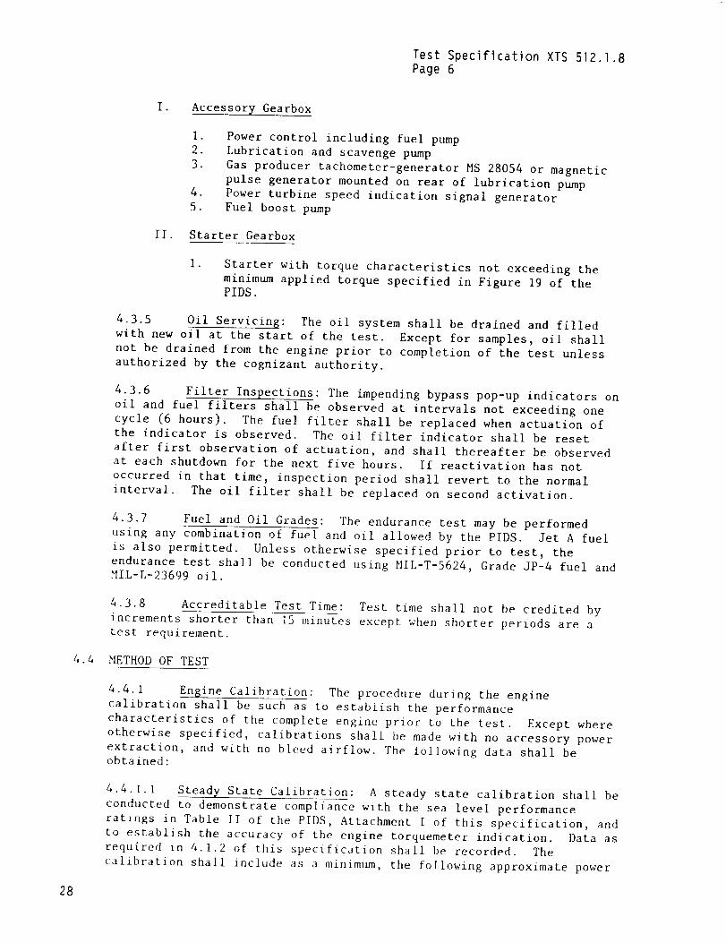
I. Accessory Gearbox
,
2.
3.
.
5.
Power control including fuel pump
Lubrication and scavenge pump
Gas producer tachometer-generator MS 28054 or magnetic
pulse generator mounted on rear of lubrication pumpPower turbine speed indication signal generator
Fuel boost pump
II. Starter Gearbox
I .
Starter with torque characteristics not exceeding the
minimum applied torque specified in Figure 19 of thePIDS.
4.3.5 Oil Servicing: The oil system shall be drained and filled
with new oil at the start of the test. Except for samples, oil shall
not be drained from the engine prior to completion of the test unless
authorized by the cognizant authority.
4.3.6 Filter Inspections: The impending bypass pop-up indicators on
oil and fuel filters shall be observed at intervals not exceeding one
cycle (6 hours). The fuel filter shall be replaced when actuation of
the indicator is observed. The oil filter indicator shall be reset
after first observation of actuation, and shall thereafter be observed
at each shutdown for the next five hours. If reactivation has not
occurred in that time, inspection period shall revert to the normal
interval. The oil filter shall be replaced on second activation.
4.3.7 Fuel and Oil Grades: The endurance test may be performed
using any combination of fuel and oil allowed by the PIDS. Jet A fuel
is also permitted. Unless otherwise specified prior to test, the
endurance test shall be conducted using MIL-T-5624, Grade JP-4 fuel andMIL-L-23699 oil.
4.3.8 Accreditable Test Time: Test time shall not be credited by
increments shorter than 15 minutes except when shorter periods are atest requirement.
4.4 METHOD OF TEST
4.4.1 Engine Calibration: The procedure during the engine
calibration shall be such as to establish the performance
characteristics of the complete engine prior to the test. Except where
otherwise specified, calibrations shall be made with no accessory power
extraction, and with no bleed airflow. The following data shall beobtained:
4.4.1.1 Steady State Calibration: A steady state calibration shall be
conducted to demonstrate compliance with the sea level performance
ratings in Table II of the PIDS, Attachment I of this specification, and
to establish the accuracy of the engine torquemeter indication. Data as
required in 4.1.2 of this specification shall be recorded. The
calibration shall include as a minimum, the following approximate power
Test Specification XTS512.1.8Page 7
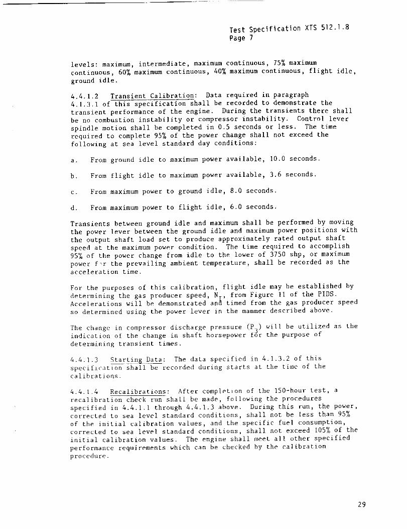
levels: maximum,intermediate, maximumcontinuous, 75%maximumcontinuous, 60%maximumcontinuous, 40%maximumcontinuous, flight idle,ground idle.
4.4.1.2 Transient Calibration: Data required in paragraph
4.1.3.1 of this specification shall be recorded to demonstrate the
transient performance of the engine. During the transients there shall
be no combustion instability or compressor instability. Control lever
spindle motion shall be completed in 0.5 seconds or less. The time
required to complete 95% of the power change shall not exceed the
following at sea level standard day conditions:
a. From ground idle to maximum power available, I0.0 seconds.
b. From flight idle to maximum power available, 3.6 seconds.
c. From maximum power to ground idle, 8.0 seconds.
d. From maximum power to flight idle, 6.0 seconds.
Transients between ground idle and maximum shall be performed by moving
the power lever between the ground idle and maximum power positions with
the output shaft load set to produce approximately rated output shaft
speed at the maximum power condition. The time required to accomplish
95% of the power change from idle to the lower of 3750 shp, or maximum
power f_r the prevailing ambient temperature, shall be recorded as the
acceleration time.
For the purposes of this calibration, flight idle may be established by
determining the gas producer speed, Nv, from Figure 11 of the PIDS.Accelerations will be demonstrated an_ timed from the gas producer speed
so determined using the power lever in the manner described above.
The change in compressor discharge pressure (P3) will be utilized as theindication of the change in shaft horsepower for the purpose of
determining transient times.
4.4.1.3 Starting Data: The data specified in 4.1.3.2 of this
specification shall be recorded during starts at the time of the
calibrations.
4.4.1.4 Recalibrations: After completion of the 150-hour test, a
recalibration check run shall be made, following the procedures
specified in 4.4.1.1 through 4.4.1.3 above. During this run, the power,corrected to sea level standard conditions, shall not be less than 95%
of the initial calibration values, and the specific fuel consumption,
corrected to sea level standard conditions, shall not exceed 105% of the
initial calibration values. The engine shall meet all other specified
performance requirements which can be checked by the calibration
procedure.
29
Test Specification XTS 512.1.8
Page 8
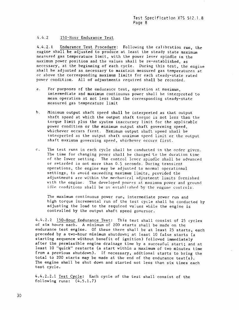
4.4.2 150-Hour Endurance Test
4.4.2.1 Endurance Test Procedure: Following the calibration run, the
engine shall be adjusted to produce at least the steady state maximum
measured gas temperature limit, with the power lever spindle in the
maximum power position and the values shall be re-established, as
necessary, at the beginning of each cycle. During this test, the engine
shall be adjusted as necessary to maintain measured gas temperatures at
or above the corresponding maximum limits for each steady-state rated
power condition. All of adjustments required shall be recorded.
a . For purposes of the endurance test, operation at maximum,
intermediate and maximum continuous power shall be interpreted to
mean operation at not less than the corresponding steady-state
measured gas temperature limit
b. Minimum output shaft speed shall be interpreted as that output
shaft speed at which the output shaft torque is not less than the
torque limit plus the system inaccuracy limit for the applicable
power condition or the minimum output shaft governing speed,
whichever occurs first. Maximum output shaft speed shall be
interpreted as the output shaft maximum speed limit or the output
shaft maximum governing speed, whichever occurs first.
C. The test runs in each cycle shall be conducted in the order given.
The time for changing power shall be charged to the duration time
of the lower setting. The control lever spindle shall be advanced
or retarded in not more than 0.5 seconds. During transient
operations, the engine may be adjusted to normal operational
settings, to avoid exceeding maximum limits, provided the
adjustments are within the mechanical adjustment limits furnished
with the engine. The developed powers at maximum power and ground
idle conditions shall be as established by the engine controls.
The maximum continuous power run, intermediate power run and
high torque incremental run of the test cycle shall be conducted by
adjusting the load to the required values while the engine is
controlled by the output shaft speed governor.
4.4.2.2 150-Hour Endurance Test: This test shall consist of 25 cyclesof six hours each. A minimum of 200 starts shall be made on the
endurance test engine. Of these there shall be at least 25 starts, each
preceded by a two-hour minimum shutdown; at least I0 false starts (a
starting sequence without benefit of ignition) followed immediately
after the permissible engine drainage time by a succesful start; and at
least I0 "quick" restarts (a start within a maximum of two minutes time
from a previous shutdown). If necessary, addtional starts to bring the
total to 200 starts may be made at the end of the endurance test(s).
The engine shall be shut down and started not less than six times each
test cycle.
4.4.2.2.1 Test Cycle: Each cycle of the test shall consist of the
following runs: (4.5.1.7)
30
Test Specification XTS 512.1.8
Page 9
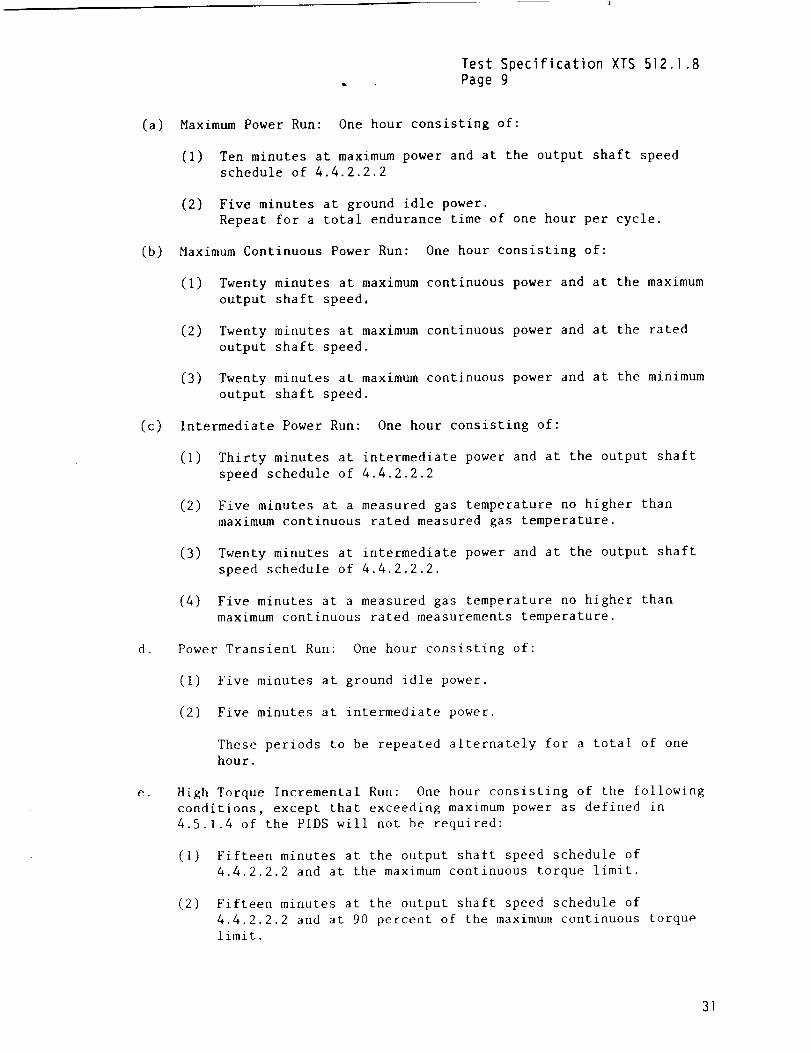
(a) Maximum Power Run: One hour consisting of:
(I) Ten minutes at maximum power and at the output shaft speed
schedule of 4.4.2.2.2
(2) Five minutes at ground idle power.
Repeat for a total endurance time of one hour per cycle.
(b) Maximum Continuous Power Run: One hour consisting of:
(I)
(2)
(3)
Twenty minutes at maximum continuous power and at the maximum
output shaft speed,
Twenty minutes at maximum continuous power and at the rated
output shaft speed.
Twenty minutes at maximum continuous power and at the minimum
output shaft speed.
(c) Intermediate Power Run: One hour consisting of:
d.
e.
(1)
(2)
Thirty minutes at intermediate power and at the output shaft
speed schedule of 4.4.2.2.2
Five minutes at a measured gas temperature no higher than
maximum continuous rated measured gas temperature.
(3)
(4)
Twenty minutes at intermediate power and at the output shaft
speed schedule of 4.4.2.2.2.
Five minutes at a measured gas temperature no higher than
maximum continuous rated measurements temperature.
Power Transient Run: One hour consisting of:
(I) Five minutes at ground idle power.
(2) Five minutes at intermediate power.
These periods to be repeated alternately for a total of one
hour.
High Torque Incremental Run: One hour consisting of the following
conditions, except that exceeding maximum power as defined in
4.5.1.4 of the PIDS will not be required:
(I) Fifteen minutes at the output shaft speed schedule of
4.4.2.2.2 and at the maximum continuous torque limit.
(2) Fifteen minutes at the output shaft speed schedule of
4.4.2.2.2 and at 90 percent of the maximum continuous torque
limit.
31
Test Specification XTS 512.1.8Page 10
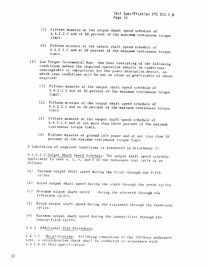
(3) Fifteen minutes at the output shaft speed schedule of
4.4.2.2.2 and at 80 percent of the maximum continuous torquelimit.
(4) Fifteen minutes at the output shaft speed schedule of
4.4.2.2.2 and at 60 percent of the maximum continuous torquelimit.
(f)Low Torque Incremental Run: One hour consisting of the followingconditions unless the required operation results in conditions
unacceptable or impractical for the power absorption device, in
which case conditions will be set as close as practicable to thoserequired:
(i) Fifteen minutes at the output shaft speed schedule of
4.4.2.2.2 and at 40 percent of the maximum continuous torquelimit.
(2) Fifteen minutes at the output shaft speedschedule of
4.4.2.2.2 and at 20 percent of the maximum continuous torquelimit.
(3) Fifteen minutes at the output shaft speed schedule of
4.4.2.2.2 and at not more than three percent of the maximum
continuous torque limit.
(4) Fifteen minutes at ground idle power and at not less than i0
percent of the maximum continuous torque limit.
A tabulation of required conditions is presented in Attachment II.
4.4.2.2.2 Output Shaft Speed Schedule: The output shaft speed schedule
applicable to runs a, c, e, and f of the endurance test cycle is asfollows:
(a) Maximum output shaft speed during the first through the fifthcycles.
(b) Rated output shaft speed during the sixth through the tenth cycles.
(c) Minimum output shaft speed
fifteenth cycles.during the eleventh through the
(d) Rated output shaft speed during the sixteenth through the twentiethcycles,
(eNaximum output shaft speed during the twenty-first through thetwenty-fifth cycles.
4.4.3 Additional Test Procedures
4.4.3.1 Recalibration: Following completion of the 150-hour endurance
test, a recalibration check shall be conducted in accordance with
4.4.1.4 of this specification
32
Test Speciflcation XTS 512.1.8
Page II
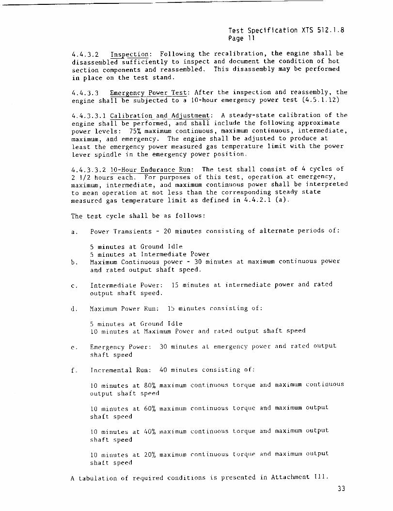
4.4.3.2 Inspection: Following the recalibration, the engine shall be
disassembled sufficiently to inspect and document the condition of hot
section components and reassembled. This disassembly may be performed
in place on the test stand.
4.4.3.3 Emergency Power Test: After the inspection and reassembly, the
engine shall be subjected to a 10-hour emergency power test (4.5.1.12)
4.4.3.3.1 Calibration and Adjustment: A steady-state calibration of the
engine shall be performed, and shall include the following approximate
power levels: 75% maximum continuous, maximum continuous, intermediate,
maximum, and emergency. The engine shall be adjusted to produce at
least the emergency power measured gas temperature limit with the power
lever spindle in the emergency power position.
4.4.3.3.2 lO-Hour Endurance Run: The test shall consist of 4 cycles of
2 I/2 hours each. For purposes of this test, operation at emergency,
maximum, intermediate, and maximum continuous power shall be interpreted
to mean operation at not less than the corresponding steady state
measured gas temperature limit as defined in 4.4.2.1 (a).
The test cycle shall be as follows:
a. Power Transients - 20 minutes consisting of alternate periods of:
b.
5 minutes at Ground Idle
5 minutes at Intermediate Power
Maximum Continuous power - 30 minutes at maximum continuous power
and rated output shaft speed.
C. Intermediate Power:
output shaft speed.
15 minutes at intermediate power and rated
d. MaximL_ Power Run: 15 minutes consisting of:
5 minutes at Ground Idle
i0 minutes at Maximum Power and rated output shaft speed
e. Emergency Power: 30 minutes at emergency power and rated output
shaft speed
f. Incremental Run: 40 minutes consisting of:
I0 minutes at 80% maximum continuous torque and maximum continuous
output shaft speed
i0 minutes at 60% maximum continuous torque and maximum output
shaft speed
I0 minutes at 40% maximum continuous torque and maximum output
shaft speed
I0 minutes at 20_ maximum continuous torque and maximum output
shaft speed
A tabulation of required conditions is presented in Attachment III.
33

Test Specification XTS 512.1.8
Page 12
.
Oscillograph recordings as specified in 4.1.3.1 shall be obtained for at
least one transient from maximum power to emergency power.
4.4.3.3.3 Recalibration: Following completion of the 10-hour emergency
power test, a recalibration similar to the calibration of 4.4.3.3.1shall be performed.
4.5 Posttest Requirements
4.5.1 Component Recalibrations:
4.5.1.I En$ine Control System Recalibration: After completion of the
endurance test, the components of the engine control system shall
undergo a bench recalibration to determine conformance with the designtolerance range required by the engine manufacturer. For this
calibration, external engine control adjustments shall be established at
their original bench calibration positions.
4.5.1.2 Temperature Sensin$ System Recalibration: After completion of
the endurance tests, the measured gas temperature system shall be
rechecked to establish its proper functioning. The performance shall
meet the design tolerance range required by the engine manufacturer.
4.5.2 Teardown Inspection: After completion of the tests on the
endurance test engine, the engine shall be disassembled as necessary for
examination of parts undergoing substantiation testing to disclose
excessively worn, distorted, or weakened parts. These measurements
shall be compared with the contractor's drawing dimensions and
tolerances or with similar measurements made prior to the test, whenavailable.
REPORT
Following completion of the endurance tests, a report shall be submittedin accordance with PIDS 124.53B
34
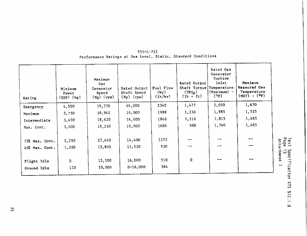
T55-L-712
Performance Ratings at Sea Level, Static, Standard Conditions
Rating
Emergency
Maximum
Intermediate
Max. Cont.
75% Max. Cont.
40% Max. Cont.
Flight Idle
Ground Idle
Minimum
Power
(SHe) (hp)
4,500
3,750
3,400
3,000
2,250
1,200
0
II0
Maximum
Gas
Generator
Speed
(Ng) (rpm)
19,750
18,940
18,620
18,250
17,440
15,820
13,100
10,300
Rated Output
Shaft Speed
(Np) (rpm)
16,000
16,000
16,000
16,000
14,400
11,530
16,000
0-16,000
Fuel Flow
(Wf)
(Iblhr)
2340
1988
1846
1686
1373
930
510
364
Rated Output
Shaft Torque
(TRQp)(Ib - ft)
1,477
1,230
I,I16
988
Rated Gas
Generator
Turbine
Inlet
Temperature
(Maximum) -
(°F)
2,050
1,885
1,815
1,740
_m
Maximum
Measured Gas
Temperature(MGT) - (OF)
1,670
1,525
1,465
1,405
_m
_u
-Q--4
tn
LO'C_
_°
_°
C_
O_
r-1-_°
O
X
-'4
Un
Do
_o
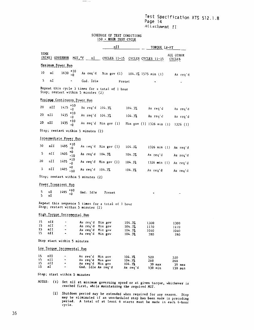
Test Speclf_cation XTSPage 14_LLact_ent II
512.1.8
SCHEDULE OF TEST CONDITIONS
150 - HOUR TEST CYCLE
TIME
(MINS) GOVERNOR MGT,°F nl
Maximum Power Run
+I0 'dI0 nl 1630 -0 As req
5 nl Gnd. Idle
nll TORQUE LB-FT
ALL OTHER
CYCLES 11-15 CYCLES CYCLES Ii-15 CYCLES
Hin gov (I) 104.3% 1575 min (I) As req'd
Preset
Repeat this cycle 3 times for a total of I hour
Stop; restart within 5 minutes (2)
Maximum Continuous Power Run............................
20 nll 1435 +I0-0 As req'd
+lO20 nll 1435 -0 As req'd
20 nll 1435 +I0-0 As req'd
Stop; restart within 5 minutes (2)
104.3% 104,3% As req'd
104.3% 104.3% As req'd
Min gov (I) Min gov (I) 1326 m£n (I)
As req'd
As req'd
1326 (I)
30 nil 1495 +i0-0 As req'd Hin gov (i) 104.3%
+0
5 nll 1405 -i0 As req'd 104.3% 104.3%
+I0
20 nll 1495 -0 As req'd Hin gov (i) 104.3%
_0 As req'a 104.3% 104.3%5 nll 1405
Stop; restart within 5 minutes (2)
1326 min (1)
As req'd
1326 min (1)
As req'd
As req'd
As req'd
As req'd
As req'd
_t_t_.!_et_l_tt_tet
5 nl 1495 +I0
5 nl -0Gnd. Idle Preset
Repeat this sequence 5 times for a total of 1 hour
Stop; restart within 5 minutes (2)
High Torque Incremental Run
15 nll As req'd Hin gov 104,3% 1300 1300
15 nll As req'd Hin gov 104.3% 1170 1170
15 nil As req'd Hin gov 104.3% 1040 1040
15 nll As req'd Hin gov 104.3% 780 780
Stop start within 5 minutes
Low Torque Incremental Run
15 nil - As reo'd Min _ov 104.3% 520 520
15 nil - As req'd Hin gov 104.3% 260 260
15 nil - As req'd Hin gov I04.3_ 39 max 39 max
15 nl - Grid. Idle As req'd As req'd 130 min 130 min
Stop; start within 5 minutes
NOTES: (i)
(2)
Set rill at minimum governing speed or at given torque, whichever is
reached first, while maintaining the required HGT.
Shutdown period may be extended when required for any reason. Stop
may be eliminated if an unscheduled stop has been made in preceding
period. A total of at least 6 starts must be made in each 6-hourcycle.
36
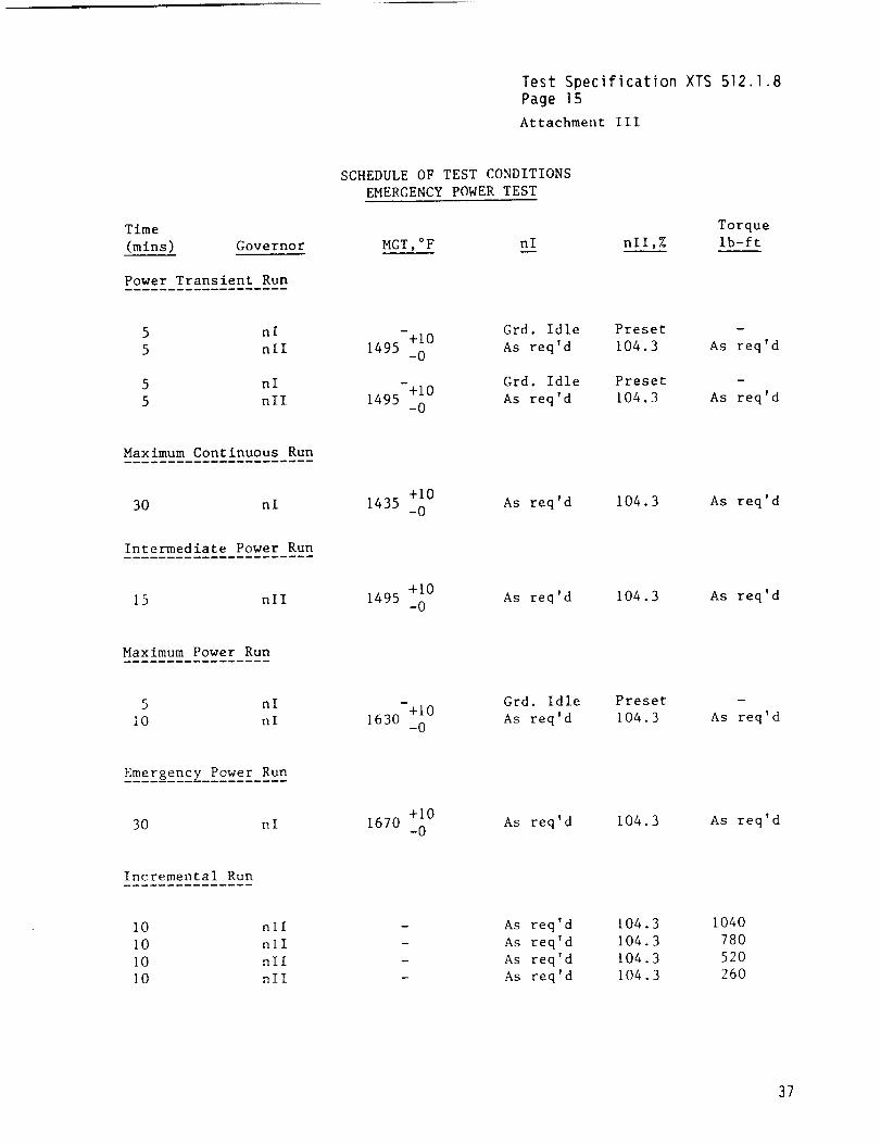
Test Specification XTS512.1.8Page 15Attachment III
Time
(rains) Governor
Power Transient Run
SCHEDULE OF TEST CONDITIONS
EMERGENCY POWER TEST
MGT,°F nl nll,%
Torque
Ib-ft
5 nl
5 nll
5 nl
5 nil
-+i0 Grd. Idle
1495 -0 As req'd
-+i0 Grd. Idle
1495 -0 As req'd
Preset
104.3
Preset
104.3
D
As req'd
As req' d
Maximum Continuous Run
30 nl
Intermediate Power Run
+i0 As req'd1435 -0
104.3 As req'd
15 nil 1495 +I0 As req'd-0
104.3 As req'd
Maximum Power Run
5 nl
i0 nl
Grd. Idle-+i0
1630 -0 As req'd
Preset
104.3
B
As req' d
Emergency Power Run
30 nl +I0 As req'd1670 -0
104.3 As req'd
Incremental Run
i0 nil
I0 nil
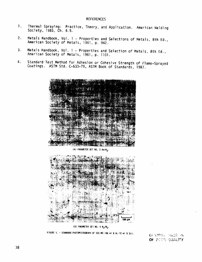
I0 nil
[0 nil
m
As req'd
As req'd
As req'd
As req'd
[04.3
104.3
104.3
104.3
1040
780
52O
260
37
I ,
.
o
.
REFERENCES
Thermal Spraying: Practice, Theory, and Application. Amerlcan WeldingSociety, 1985, Ch. 6.5.
Metals Handbook, Vol. I - Properties and Selections of Metals, 8th Ed.,American Society of Metals, ]961, p. 942.
Metals Handbook, Vol. I - Properties and Selection of Metals, 8th Ed.,American Society of Metals, 1961, p. 1101.
Standard Test Method for Adhesion or Cohesive Strength of Flame-SprayedCoatings. ASTM Std. C-633-79, ASTM Book of Standards, 1987.
(A) PARAMETERSET NO. 3 AR/H2,
t_
_ 100 pM
(B) PARAMETERSET NO. q N2/H 2.
FIGURE 1. - STANDARDPHOTOMICROGRAPHOF 52C-NS (88 wt % At-12 WT _ SI).
Oi_ _:;C::,_'_,__LJ;_L_Y
38
_eT..__
I_. POOR QU_LrT'Y
- _
A_.",,t,"- _ '_ " "_ "-_ _ "
(A) PARAMETER SET NO. 3 AR/H2.
(B) PARAMETER SET NO, q N21H2.
FIGURE 2. - STANDARD PHOTOI'IICROGRAPHOF qSO-NS (95 WT % NI-5 WT % AL
COMPOSITE).
39
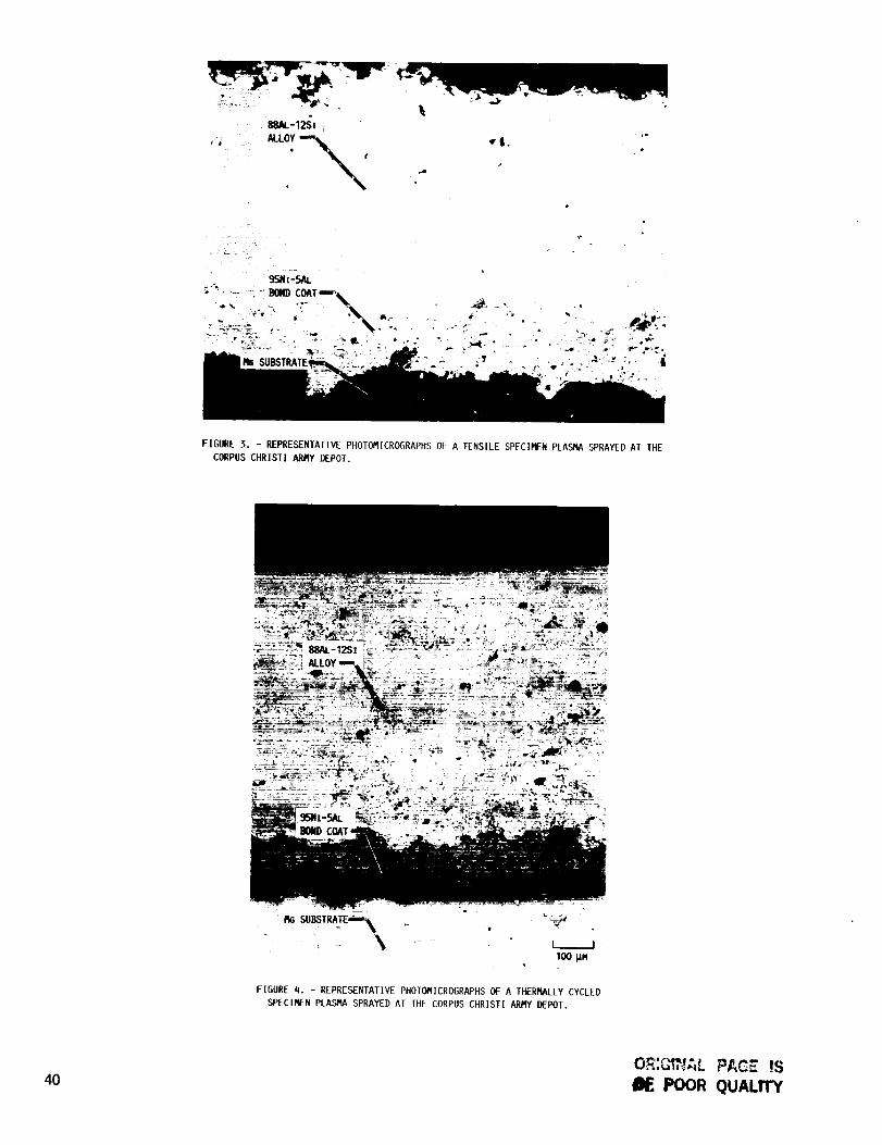
FIGURE 3. - REPRESENTATIVE PHOTOMICROGRAPHS OF A TENSILE SPECIMEN PLASMA SPRAYED AT THE
CORPUS CHRISTI ARMY DEPOT.
FIGURE q. - REPRESENTATIVE PHOTOMICROGRAPHS OF A THERMALLY CYCLED
SPECIMEN PLASMA SPRAYED AT THE CORPUS CHRISTI ARMY DEPOT.
40O_:_'_'_,_LPAC_ _s
POOR QUALITY
OE POOR QUAL.rT'Y
FIGURE 5. - REPRESENTATIVE PHOTOMICROGRAPHS OF SPECIMENS TAKEN FROM THE COMPRESSOR HOUSING
THAT WAS IN THE 150-HR ENDURANCE AND IO-HR EMERGENCY POWER TEST. SPECIMENS WERE PLASMA
SPRAYED AT THE CORPUS CHRISTI ARMY DEPOT.
41
OF POOR (__
FIGURE6. - REPRESENTATIVEBACKSCATTEREDSCANNINGELECTRONPHOTORICROGRAPHSOF SPECIMENSTAKENFRORTHE COI_RESSORHOUSINGWHICHWASIN THE200 He FLIGHTTEST. SPECIRENSWEREPLASMASPRAYEDAT THECORPUSCHRISTI ARMYDEPOT.
42
Report Documentation PageNational Aeronautics andSpace Administration
1. Report No. NASA TM-101310 2. Government Accession No. 3. Recipient's Catalog No.
AVSCOM TM-88-C-006
5. Report Date
October 1988
4. Title and Subtitle
T55-L-712 Turbine Engine Compressor Housing Refurbishment--Plasma
Spray Project
7. Author(s)
George W. Leissler and John S. Yuhas
9. Performing Organization Name and Address
NASA Lewis Research Center
Cleveland, Ohio 44135-3191
and
Propulsion DirectorateU.S. Army Aviation Research and Technology Activity--AVSCOM
Cleveland, Ohio 44135-3127
12. Sponsoring Agency Name and Address
National Aeronautics and Space Administration
Washington, D.C. 20546-0001and
U.S. Army Aviation Systems CommandSt. Louis, Mo. 63120-1798
6. Performing Organization Code
8. Performing Organization Report No.
E-4301
10. Work Unit No.
1L 162209AH76
505-62-0K
11. Contract or Grant No.
13. Type of Report and Period Covered
Technical Memorandum
14. Sponsoring Agency Code
15. Supplementary Notes
George W. Leissler, Sverdrup Technology, Inc., NASA Lewis Research Center Group, Cleveland, Ohio 44135;John S. Yuhas, Propulsion Directorate. Appendix A--T55-L-712 Compressor Housing Refurbishment Procedure
by Carl Reitenbach, Propulsion Directorate; George Leissler, Sverdrup Technology, Inc.; and Cliff Darling and
George Gilchrist, Corpus Christi Army Depot, Corpus Christi, Texas 78419. Appendix B--Avco Lycoming Test
Specificaiton by J. Kozub, Avco Lycoming Textron, Stratford, Connecticut 06497.
16. Abstract
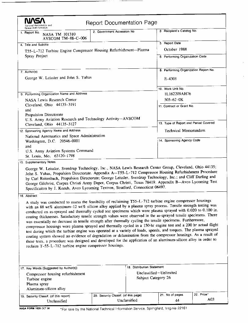
A study was conducted to assess the feasibility of reclaiming T55-L-712 turbine engine compressor housingswith an 88 wt% aluminum-12 wt% silicon alloy applied by a plasma spray process. Tensile strength testing was
conducted on as-sprayed and thermally cycled test specimens which were plasma sprayed with 0.020 to 0.100 in.
coating thicknesses. Satisfactory tensile strength values were observed in the as-sprayed tensile specimens. There
was essentially no decrease in tensile strength after thermally cycling the tensile specimens. Furthermore,
compressor housings were plasma sprayed and thermally cycled in a 150-hr engine test and a 200 hr actual flight
test during which the turbine engine was operated at a variety of loads, speeds, and torques. The plasma sprayed
coating system showed no evidence of degradation or delamination from the compressor housings. As a result of
these tests, a procedure was designed and developed for the application of an aluminum-silicon alloy in order to
reclaim T-55-L-712 turbine engine compressor housings.
17. Key Words (Suggested by Author(s))
Compressor housing refurbishment
Turbine engine
Plasma sprayAluminum-silicon alloy
19. Security Classif. (of this report) 20. Security Classif. (of this page)
Unclassified Unclassified
NASA FORM 1626 OCT 8,6
18. Distribution Statement
Unclassified - Unlimited
Subject Category 26
21. No of pages
44
*For sale by the National Technical Information Service, Springfield, Virginia 22161
22, Price*
A03


National Aeronautics and
Space Administration
Lewis Research Center
Cleveland, Ohio 44135
Offlc_l Bu=dneu
Penalty for Private Use $300
FOURTH CLASS MAIL
ADDRESS CORRECTION REQUESTED
IIIIII
Postage and Fees PaidNal_onal Aeronautics and
Space Ad mlrilstr atlor_
NASA 45_