t2 femoral nailing system - az621074.vo.msecnd.netaz621074.vo.msecnd.net/syk-mobile-content-cdn/...9...
TRANSCRIPT
Operative technique
T2® Femoral Nailing System
2
T2 Femoral Nailing System | Operative technique
Contents
1. Indications, precautions and contraindications. . .4 Indications . . . . . . . . . . . . . . . . . . . . . . . . . . . . . . . .4 Precautions . . . . . . . . . . . . . . . . . . . . . . . . . . . . . . . .4 Contraindications . . . . . . . . . . . . . . . . . . . . . . . . . . .4
2 . Introduction . . . . . . . . . . . . . . . . . . . . . . . . . . . . . . 5 Implant features . . . . . . . . . . . . . . . . . . . . . . . . . . . .5 Instrument features . . . . . . . . . . . . . . . . . . . . . . . . .6
3. Additional information . . . . . . . . . . . . . . . . . . . . . 7 Locking options . . . . . . . . . . . . . . . . . . . . . . . . . . . .7
4. Pre-operative planning . . . . . . . . . . . . . . . . . . . . . 9
5. Retrograde technique . . . . . . . . . . . . . . . . . . . . . . . . .10 Patient positioning . . . . . . . . . . . . . . . . . . . . . . . . .10 Incision . . . . . . . . . . . . . . . . . . . . . . . . . . . . . . . . . .10 Entry point . . . . . . . . . . . . . . . . . . . . . . . . . . . . . . .11 Unreamed technique . . . . . . . . . . . . . . . . . . . . . . .13 Reamed technique . . . . . . . . . . . . . . . . . . . . . . . . .13 Nail selection . . . . . . . . . . . . . . . . . . . . . . . . . . . . .15 Nail insertion . . . . . . . . . . . . . . . . . . . . . . . . . . . . .16 Guided locking mode (via target device) . . . . . . . .18 Static locking mode . . . . . . . . . . . . . . . . . . . . . . . .19 Freehand proximal locking . . . . . . . . . . . . . . . . . .23 End cap Insertion . . . . . . . . . . . . . . . . . . . . . . . . . .25 Dynamic locking mode . . . . . . . . . . . . . . . . . . . . . .26 Apposition /compression locking mode . . . . . . . . .26 Advanced locking mode . . . . . . . . . . . . . . . . . . . . .29 External compression device . . . . . . . . . . . . . . . . .31 Nail removal . . . . . . . . . . . . . . . . . . . . . . . . . . . . . .33
6. Antegrade technique . . . . . . . . . . . . . . . . . . . . . . 34 Patient positioning and fracture reduction . . . . . .34 Incision . . . . . . . . . . . . . . . . . . . . . . . . . . . . . . . . . .34 Entry point . . . . . . . . . . . . . . . . . . . . . . . . . . . . . . .35 Unreamed technique . . . . . . . . . . . . . . . . . . . . . . .36 Reamed technique . . . . . . . . . . . . . . . . . . . . . . . . .36 Nail selection . . . . . . . . . . . . . . . . . . . . . . . . . . . . .38 Nail insertion . . . . . . . . . . . . . . . . . . . . . . . . . . . . .39 Guided locking mode (via target device) . . . . . . . .42 Static locking mode . . . . . . . . . . . . . . . . . . . . . . . .43 Freehand distal locking . . . . . . . . . . . . . . . . . . . . .45 End cap insertion . . . . . . . . . . . . . . . . . . . . . . . . . .46 Dynamic locking mode . . . . . . . . . . . . . . . . . . . . . .47 Apposition /compression locking mode . . . . . . . . .48 Advanced locking mode . . . . . . . . . . . . . . . . . . . . .50 External compression device . . . . . . . . . . . . . . . . .50 Nail removal . . . . . . . . . . . . . . . . . . . . . . . . . . . . . .52
T2® FemoralNailing System
3
Operative technique | T2 Femoral Nailing System
This publication sets forth detailed recommended procedures for using Stryker devices and instruments . It offers guidance that you should heed, but, as with any such technical guide, each surgeon must consider the particular needs of each patient and make appropriate adjustments when and as required . A workshop training is recommended prior to performing your first surgery. All non-sterile devices must be cleaned and sterilized before use .
Follow the instructions provided in our cleaning and sterilization guide (L24002000). Multi-component instruments must be disassembled for cleaning . Please refer to the corresponding assembly/disassembly instructions .
Please remember that the compatibility of different product systems have not been tested unless specified otherwise in the product labeling .
See package insert (Instruction for Use) (L220105B6 & L22000007) for a complete list of potential adverse effects, contraindications, warnings and precautions . The surgeon must discuss all relevant risks including the finite lifetime of the device with the patient when necessary .
Warning:
Fixation screws: Stryker Ostreosynthesis bone screws are not approved or intended for screw attachment or fixation to the posterior elements (pedicles) of the cervical, thoracic or lumbar spine .
4
T2 Femoral Nailing System | Operative technique
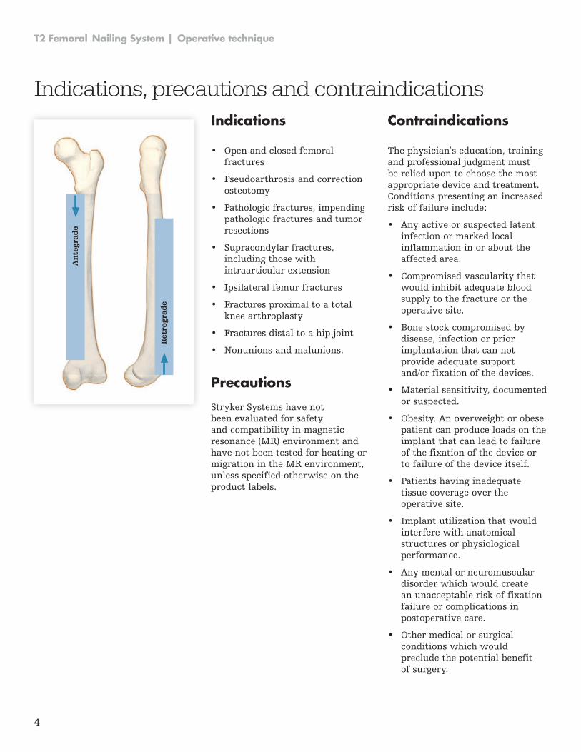
Indications
• Open and closed femoral fractures
• Pseudoarthrosis and correction osteotomy
• Pathologic fractures, impending pathologic fractures and tumor resections
• Supracondylar fractures, including those with intraarticular extension
• Ipsilateral femur fractures
• Fractures proximal to a total knee arthroplasty
• Fractures distal to a hip joint
• Nonunions and malunions .
Precautions Stryker Systems have not been evaluated for safety and compatibility in magnetic resonance (MR) environment and have not been tested for heating or migration in the MR environment, unless specified otherwise on the product labels .
Contraindications
The physician’s education, training and professional judgment must be relied upon to choose the most appropriate device and treatment . Conditions presenting an increased risk of failure include:
• Any active or suspected latent infection or marked local inflammation in or about the affected area .
• Compromised vascularity that would inhibit adequate blood supply to the fracture or the operative site .
• Bone stock compromised by disease, infection or prior implantation that can not provide adequate support and/or fixation of the devices .
• Material sensitivity, documented or suspected .
• Obesity . An overweight or obese patient can produce loads on the implant that can lead to failure of the fixation of the device or to failure of the device itself .
• Patients having inadequate tissue coverage over the operative site .
• Implant utilization that would interfere with anatomical structures or physiological performance .
• Any mental or neuromuscular disorder which would create an unacceptable risk of fixation failure or complications in postoperative care .
• Other medical or surgical conditions which would preclude the potential benefit of surgery .
Indications, precautions and contraindicationsA
nte
grad
e
Ret
rogr
ade
5
Operative technique | T2 Femoral Nailing System
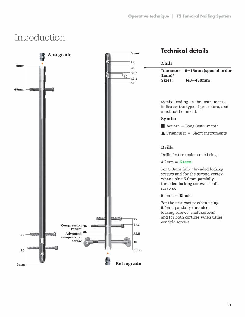
Introduction
45mm
0mm
Antegrade
50
25
0mm
60
47.5
32.5
15
0mm
0mm
25
15
42.550
32.53540
Retrograde
Advanced compression
screw
45
35
Compression range*
Technical details
Nails
Diameter: 9−15mm (special order 8mm)* Sizes: 140−480mm
Symbol coding on the instruments indicates the type of procedure, and must not be mixed .
Symbol
n Square = Long instruments
s Triangular = Short instruments
Drills
Drills feature color coded rings:
4 .2mm = Green
For 5 .0mm fully threaded locking screws and for the second cortex when using 5 .0mm partially threaded locking screws (shaft screws) .
5 .0mm = Black
For the first cortex when using 5 .0mm partially threaded locking screws (shaft screws) and for both cortices when using condyle screws .
6
T2 Femoral Nailing System | Operative technique
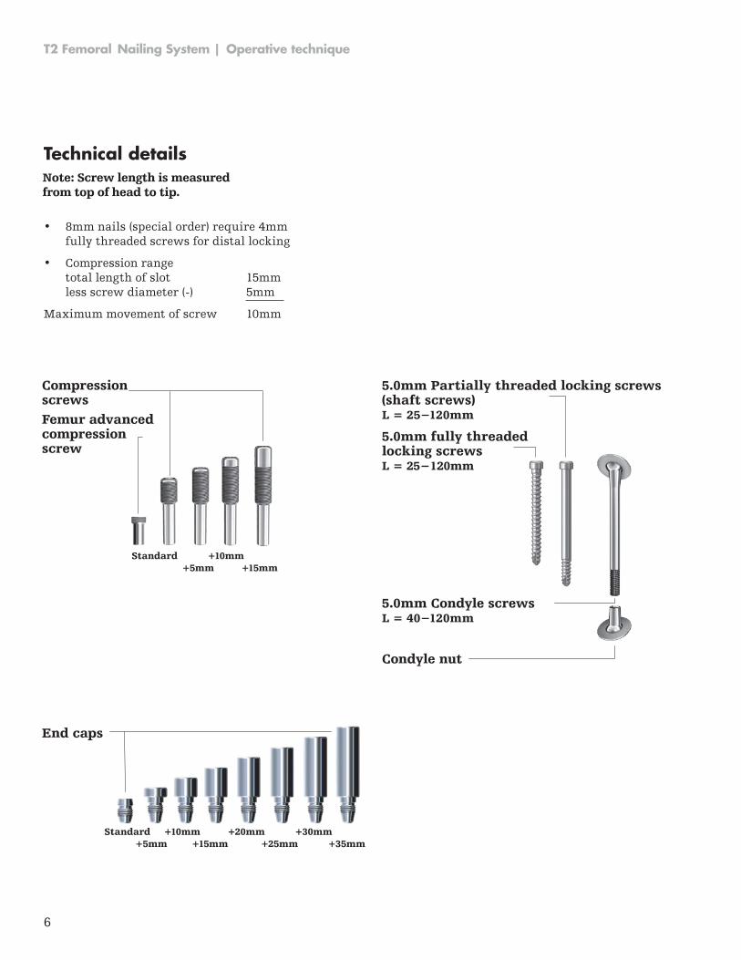
Technical detailsNote: Screw length is measured from top of head to tip.
• 8mm nails (special order) require 4mm fully threaded screws for distal locking
• Compression range total length of slot 15mm less screw diameter (-) 5mm
Maximum movement of screw 10mm
Standard +10mm+5mm +15mm
Compression screwsFemur advancedcompression screw
Standard +10mm +20mm +30mm+5mm +15mm +25mm +35mm
End caps
Condyle nut
5.0mm fully threadedlocking screwsL = 25−120mm
5.0mm Partially threaded locking screws (shaft screws)L = 25−120mm
5.0mm Condyle screwsL = 40−120mm
7
Operative technique | T2 Femoral Nailing System
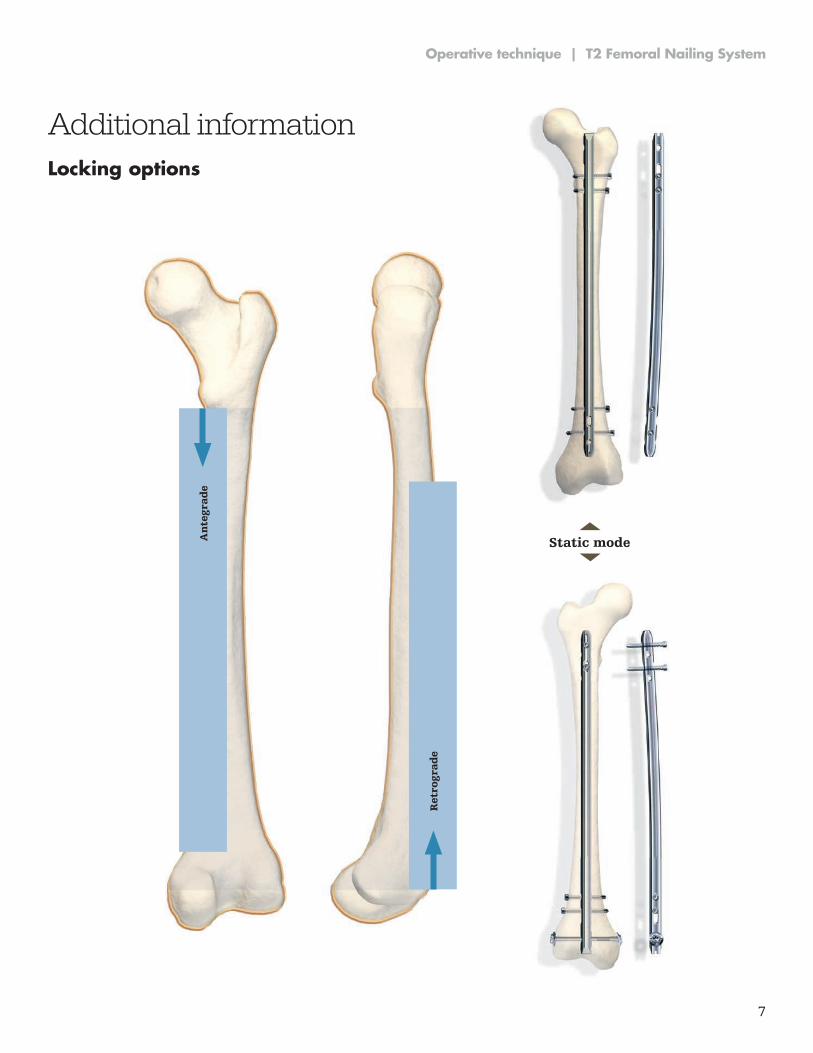
Additional informationLocking options
Static modeAn
tegr
ade
Ret
rogr
ade
8
T2 Femoral Nailing System | Operative technique
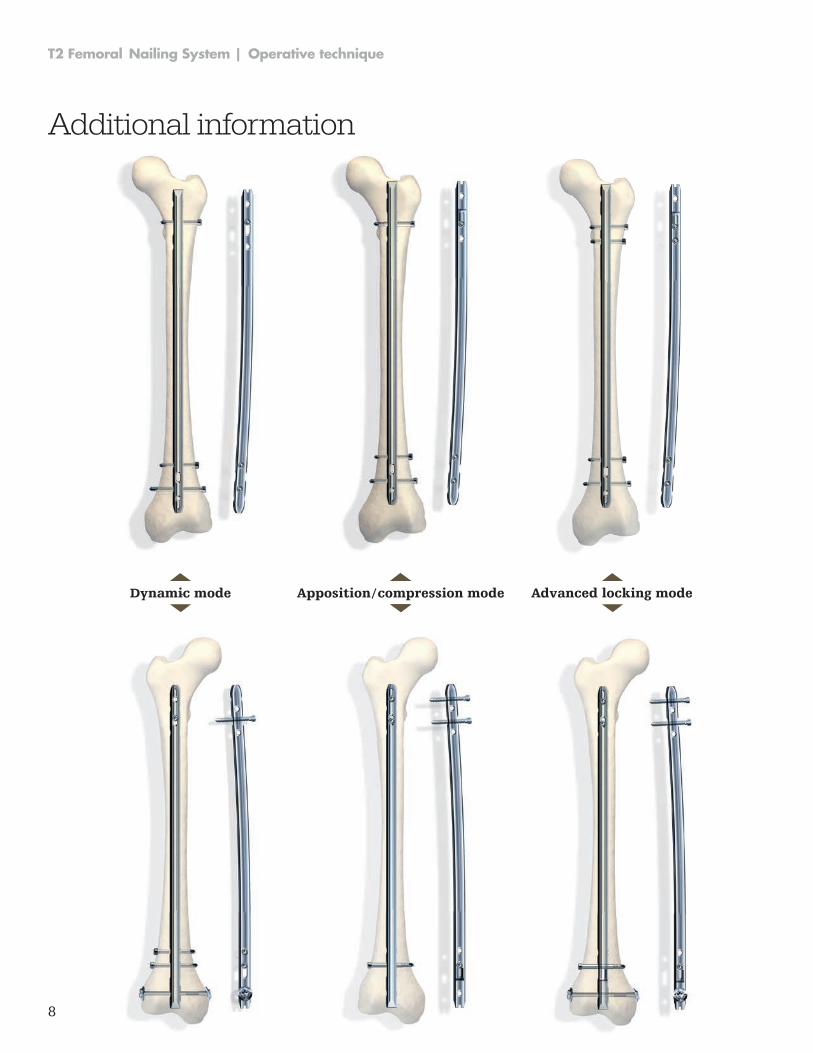
Additional information
Dynamic mode Apposition / compression mode Advanced locking mode
9
Operative technique | T2 Femoral Nailing System
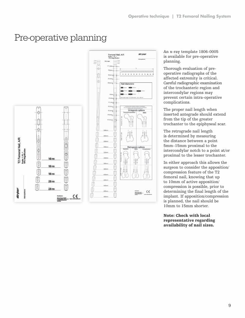
An x-ray template 1806-0005 is available for pre-operative planning .
Thorough evaluation of pre-operative radiographs of the affected extrem ity is critical . Careful radiographic ex am ination of the trochanteric region and intercondylar regions may prevent certain intra-operative complications .
The proper nail length when inserted antegrade should extend from the tip of the greater trochanter to the epiphyseal scar .
The retrograde nail length is determined by measuring the distance between a point 5mm–15mm proxi mal to the intercondylar notch to a point at/or proximal to the lesser trochanter .
In either approach this allows the surgeon to consider the apposition/compression feature of the T2 femo ral nail, knowing that up to 10mm of active apposition/compression is possible, prior to determining the final length of the implant . If apposition/compression is planned, the nail should be 10mm to 15mm shorter .
Pre-operative planning
Note: Check with local representative regarding availability of nail sizes.
10
T2 Femoral Nailing System | Operative technique
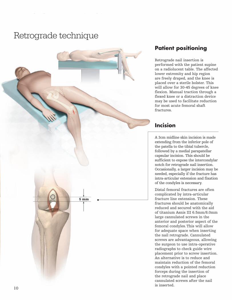
Patient positioning
Retrograde nail insertion is performed with the patient supine on a radiolucent table . The affected lower extremity and hip region are freely draped, and the knee is placed over a sterile bolster . This will allow for 30-45 degrees of knee flexion . Manual traction through a flexed knee or a distraction device may be used to facilitate reduction for most acute femoral shaft fractures .
Incision
A 3cm midline skin incision is made extending from the inferior pole of the patella to the tibial tubercle, followed by a medial parapatellar capsular in ci sion . This should be sufficient to expose the intercondylar notch for retrograde nail insertion . Occasionally, a larger incision may be needed, espe cially if the fracture has intra-articular extension and fixation of the condyles is necessary .
Distal femoral fractures are often complicated by intra-articular fracture line extension . These fractures should be anatomically reduced and secured with the aid of titanium Asnis III 6 .5mm/8 .0mm large cannulated screws in the anterior and posterior aspect of the femoral condyles . This will allow for adequate space when inserting the nail retrograde . Cannu lated screws are advantageous, al low ing the surgeon to use intra-operative radiographs to check guide wire place ment prior to screw insertion . An alternative is to reduce and maintain reduction of the femoral condyles with a pointed reduction forceps during the insertion of the retrograde nail and place cannulated screws after the nail is inserted .
Retrograde technique
5 mm
11
Operative technique | T2 Femoral Nailing System
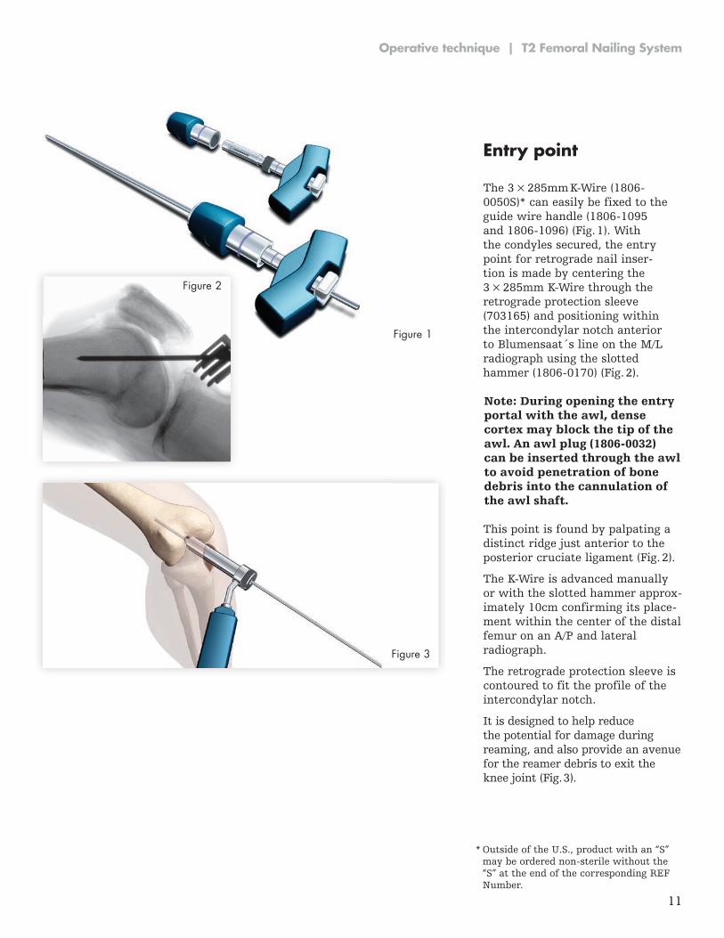
Entry point
The 3 × 285mm K-Wire (1806-0050S)* can easily be fixed to the guide wire handle (1806-1095 and 1806-1096) (Fig. 1). With the condyles secured, the entry point for retrograde nail in ser-tion is made by centering the 3 × 285mm K-Wire through the retrograde protection sleeve (703165) and positioning within the intercondylar notch anterior to Blumensaat´s line on the M/L radiograph using the slotted hammer (1806-0170) (Fig. 2).
Note: During opening the entry portal with the awl, dense cortex may block the tip of the awl. An awl plug (1806-0032) can be inserted through the awl to avoid penetration of bone debris into the cannulation of the awl shaft.
* Outside of the U .S ., product with an “S” may be ordered non-sterile without the “S” at the end of the corresponding REF Number .
Figure 2
Figure 1
Figure 3
This point is found by palpating a distinct ridge just anterior to the posterior cruciate ligament (Fig . 2) .
The K-Wire is advanced manually or with the slotted hammer ap prox-i mately 10cm confirming its place -ment within the center of the distal femur on an A/P and lateral radiograph .
The retrograde protection sleeve is contoured to fit the profile of the intercondylar notch .
It is designed to help reduce the potential for damage during reaming, and also provide an avenue for the reamer debris to exit the knee joint (Fig . 3) .
12
T2 Femoral Nailing System | Operative technique
12
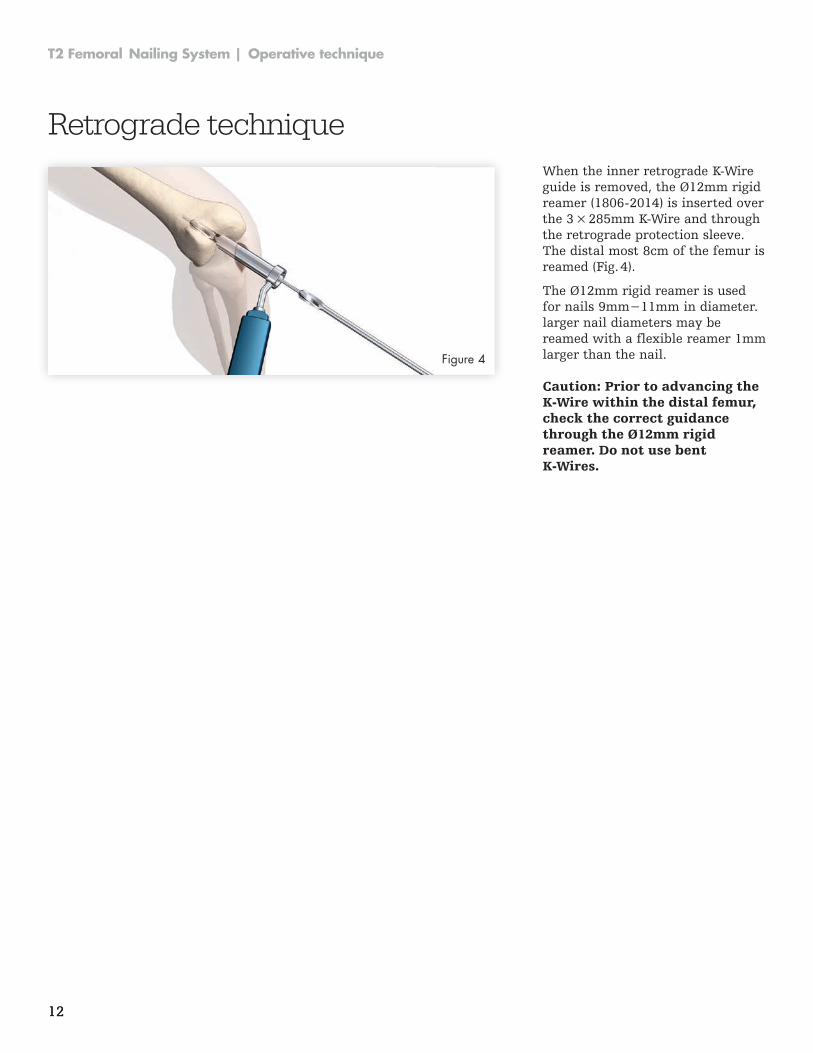
Retrograde techniqueWhen the inner retrograde K-Wire guide is removed, the Ø12mm rigid reamer (1806-2014) is inserted over the 3 × 285mm K-Wire and through the retrograde protection sleeve . The distal most 8cm of the femur is reamed (Fig . 4) .
The Ø12mm rigid reamer is used for nails 9mm−11mm in diameter. larger nail diameters may be reamed with a flexible reamer 1mm larger than the nail .Figure 4
Caution: Prior to advancing the K-Wire within the distal femur, check the correct guidance through the Ø12mm rigid reamer. Do not use bent K-Wires.
13
Operative technique | T2 Femoral Nailing System
13
Note: The ball tip at the end of the guide wire will stop the reamer head.
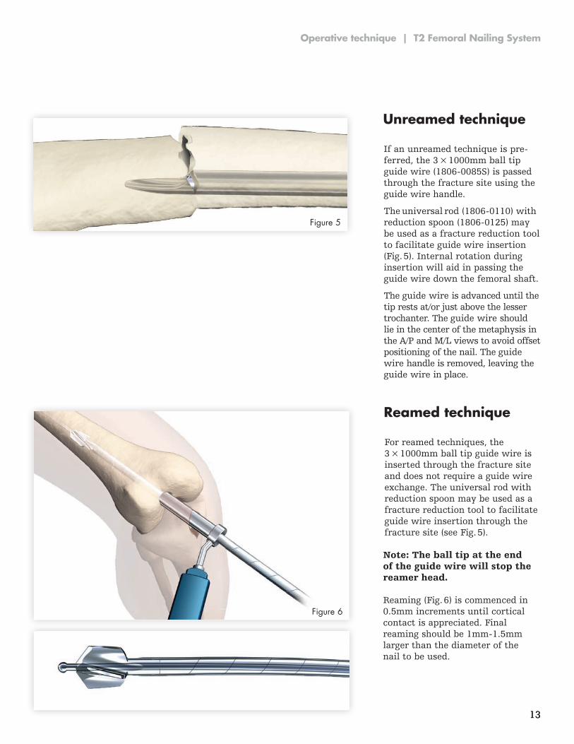
Unreamed technique
Reamed technique
If an unreamed technique is pre -ferred, the 3 × 1000mm ball tip guide wire (1806-0085S) is passed through the fracture site using the guide wire handle .
The universal rod (1806-0110) with reduction spoon (1806-0125) may be used as a fracture reduction tool to facilitate guide wire insertion (Fig . 5) . Internal rotation during insertion will aid in passing the guide wire down the femoral shaft .
The guide wire is advanced until the tip rests at/or just above the lesser trochanter . The guide wire should lie in the center of the metaphysis in the A/P and M/L views to avoid offset positioning of the nail . The guide wire handle is removed, leaving the guide wire in place .
For reamed techniques, the 3 × 1000mm ball tip guide wire is inserted through the fracture site and does not require a guide wire exchange . The universal rod with reduction spoon may be used as a fracture reduction tool to facilitate guide wire insertion through the fracture site (see Fig . 5) .
Figure 5
Figure 6Reaming (Fig . 6) is commenced in 0 .5mm increments until cortical contact is appreciated . Final reaming should be 1mm-1.5mm larger than the diameter of the nail to be used .
14
T2 Femoral Nailing System | Operative technique
Caution: The diameter of the driving end of the 9mm–11mm (and special oder 8mm nails) diameter nails is 11.5mm. Additional metaphyseal reaming may be required to facilitate nail insertion. Nail sizes 12–15mm have a constant diameter.
Thoroughly irrigate the knee joint to remove any debris.
Figure 7
Figure 8
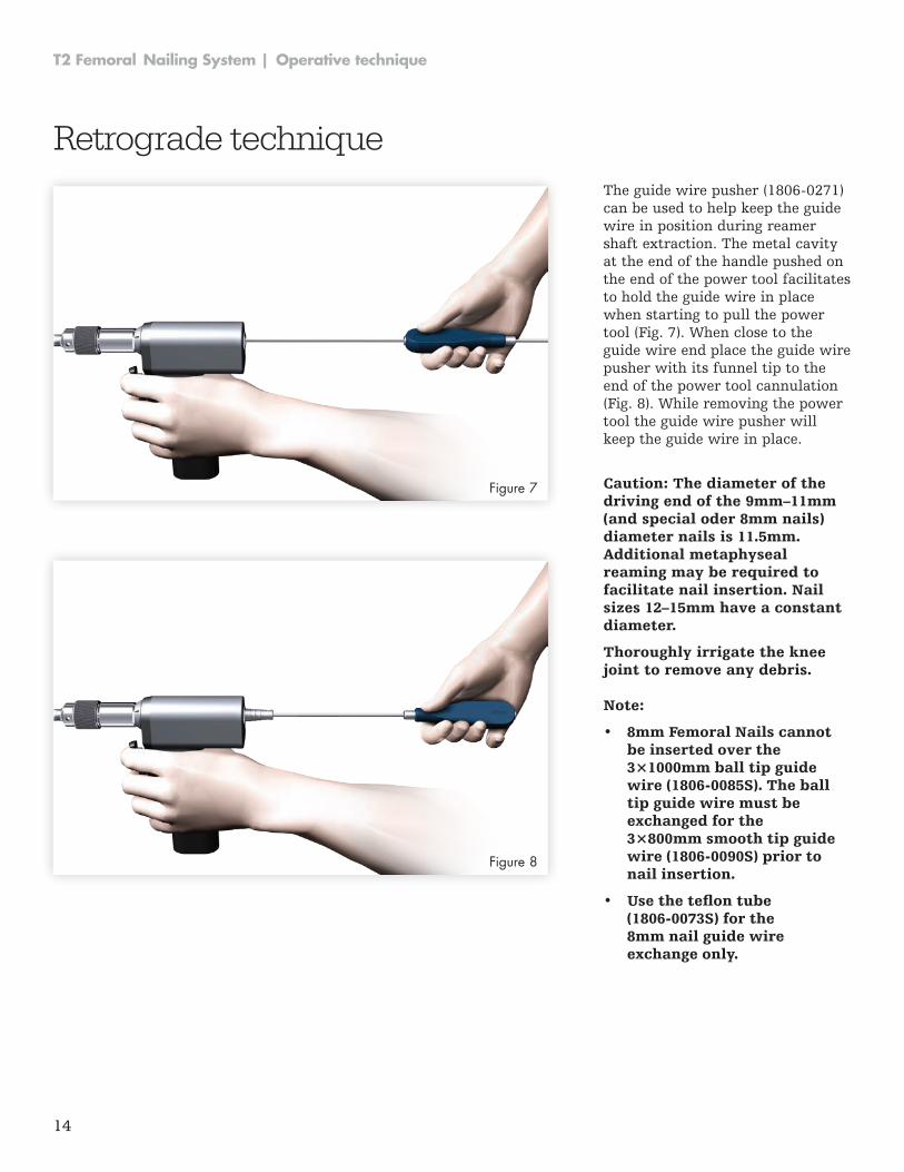
Retrograde techniqueThe guide wire pusher (1806-0271) can be used to help keep the guide wire in position during reamer shaft extraction . The metal cavity at the end of the handle pushed on the end of the power tool facilitates to hold the guide wire in place when starting to pull the power tool (Fig. 7). When close to the guide wire end place the guide wire pusher with its funnel tip to the end of the power tool cannulation (Fig. 8). While removing the power tool the guide wire pusher will keep the guide wire in place .
Note:
• 8mm Femoral Nails cannot be inserted over the 3×1000mm ball tip guide wire (1806-0085S). The ball tip guide wire must be exchanged for the 3×800mm smooth tip guide wire (1806-0090S) prior to nail insertion.
• Use the teflon tube (1806-0073S) for the 8mm nail guide wire exchange only.
15
Operative technique | T2 Femoral Nailing System
Note: X-ray ruler and guide wire Ruler can be used for nail length determination beginning from 240mm. Shorter nail length can be determined via the template.
Figure 9.1
Figure 9.2
Nail selection
3 1 2 1
Length Scale Diameter Scale
Length
330 mm
Length Calibration
Hole Positions(driving end)
Static and Dynamic Slot Locking Options
1 2 1
End of Guide Wire Ruler is the measurement reference Figure 10
The guide wire ruler can be easily folded and unfolded .
Caution: If the fracture is suitable for apposition/compression, the implant selected should be 10–15mm shorter than measured, to help avoid migration of the nail beyond the insertion site.
* See pages 7-8 for detailed illustrations of antegrade and retrograde locking options .
Figure 11
Diameter
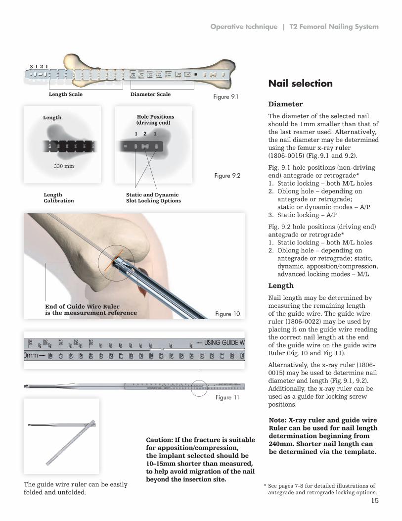
The diameter of the selected nail should be 1mm smaller than that of the last reamer used . Alternatively, the nail diameter may be determined using the femur x-ray ruler (1806-0015) (Fig. 9.1 and 9.2).
Fig. 9.1 hole positions (non-driving end) antegrade or retrograde*1 . Static locking – both M/L holes2 . Oblong hole – depending on
antegrade or retrograde; static or dynamic modes – A/P
3 . Static locking – A/P
Fig . 9 .2 hole positions (driving end) antegrade or retrograde*1 . Static locking – both M/L holes2 . Oblong hole – depending on
antegrade or retrograde; static, dynamic, apposition/compression, advanced locking modes – M/L
Length
Nail length may be determined by measuring the remaining length of the guide wire . The guide wire ruler (1806-0022) may be used by placing it on the guide wire reading the correct nail length at the end of the guide wire on the guide wire Ruler (Fig . 10 and Fig . 11) .
Alternatively, the x-ray ruler (1806-0015) may be used to determine nail diameter and length (Fig . 9 .1, 9 .2) . Additionally, the x-ray ruler can be used as a guide for locking screw positions .
16
T2 Femoral Nailing System | Operative technique
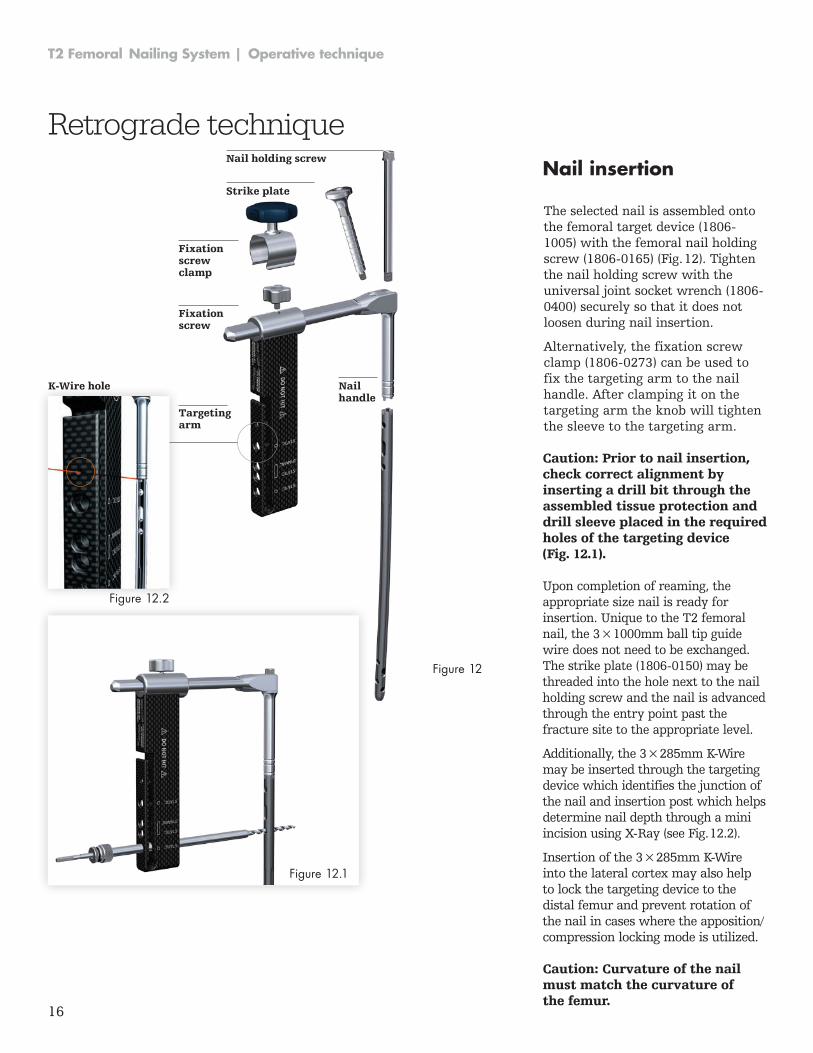
Nail insertion
The selected nail is assembled onto the femoral target device (1806-1005) with the femoral nail holding screw (1806-0165) (Fig. 12). Tighten the nail holding screw with the universal joint socket wrench (1806-0400) securely so that it does not loosen during nail insertion .
Alternatively, the fixation screw clamp (1806-0273) can be used to fix the targeting arm to the nail handle . After clamping it on the targeting arm the knob will tighten the sleeve to the targeting arm .
Retrograde technique
Targetingarm
Nailhandle
Fixationscrew
Fixation screw clamp
Nail holding screw
Strike plate
K-Wire hole
Caution: Prior to nail insertion, check correct alignment by inserting a drill bit through the assembled tissue protection and drill sleeve placed in the required holes of the targeting device (Fig. 12.1).
Caution: Curvature of the nail must match the curvature of the femur.
Upon completion of reaming, the appropriate size nail is ready for in ser tion . Unique to the T2 femoral nail, the 3 × 1000mm ball tip guide wire does not need to be exchanged . The strike plate (1806-0150) may be threaded into the hole next to the nail holding screw and the nail is advanced through the entry point past the fracture site to the appropriate level .
Additionally, the 3 × 285mm K-Wire may be inserted through the targeting device which identifies the junction of the nail and insertion post which helps determine nail depth through a mini incision using X-Ray (see Fig. 12.2).
Insertion of the 3 × 285mm K-Wire into the lateral cortex may also help to lock the targeting device to the distal femur and prevent rotation of the nail in cases where the apposition/compression locking mode is utilized .
Figure 12
Figure 12.1
Figure 12.2
17
Operative technique | T2 Femoral Nailing System
Nail insertion
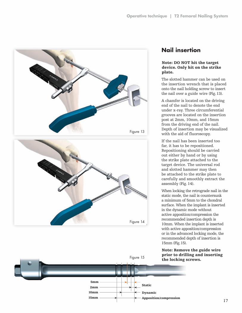
Note: DO NOT hit the target device. Only hit on the strike plate.
Note: Remove the guide wire prior to drilling and inserting the locking screws.
The slotted hammer can be used on the insertion wrench that is placed onto the nail holding screw to insert the nail over a guide wire (Fig . 13) .
A chamfer is located on the driving end of the nail to denote the end under x-ray. Three circumferential grooves are located on the insertion post at 2mm, 10mm, and 15mm from the driving end of the nail . Depth of insertion may be visualized with the aid of fluoroscopy .
If the nail has been inserted too far, it has to be repositioned . Repositioning should be carried out either by hand or by using the strike plate attached to the target device . The universal rod and slotted hammer may then be attached to the strike plate to carefully and smoothly extract the assembly (Fig . 14) .
When locking the retrograde nail in the static mode, the nail is countersunk a minimum of 5mm to the chondral surface. When the implant is inserted in the dynamic mode without active apposition/compression the recommended insertion depth is 10mm. When the implant is inserted with active apposition/compression or in the advanced locking mode, the recommended depth of insertion is 15mm (Fig . 15) .
Figure 13
Figure 14
Figure 15
Static
Dynamic
Apposition/compression15mm
10mm
2mm
5mm
18
T2 Femoral Nailing System | Operative technique
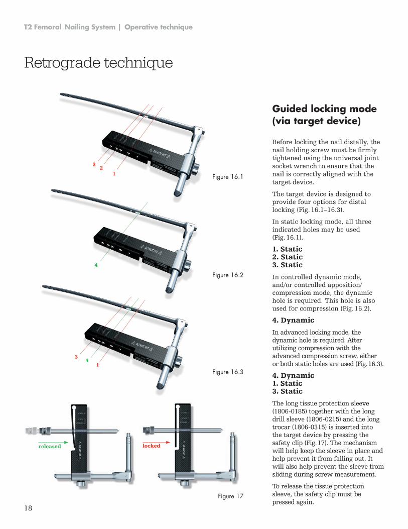
Guided locking mode (via target device) Before locking the nail distally, the nail holding screw must be firmly tightened using the universal joint socket wrench to ensure that the nail is correctly aligned with the target device .
The target device is designed to provide four options for distal locking (Fig . 16 .1–16 .3) .
In static locking mode, all three indicated holes may be used (Fig . 16 .1) .
1. Static 2. Static 3. Static
In controlled dynamic mode, and/or controlled apposition/compression mode, the dynamic hole is required . This hole is also used for compression (Fig . 16 .2) .
4. Dynamic
In advanced locking mode, the dynamic hole is required . After utilizing compression with the advanced compression screw, either or both static holes are used (Fig . 16 .3) .
4. Dynamic 1. Static 3. Static
The long tissue protection sleeve (1806-0185) together with the long drill sleeve (1806-0215) and the long trocar (1806-0315) is inserted into the target device by pressing the safety clip (Fig . 17) . The mechanism will help keep the sleeve in place and help prevent it from falling out . It will also help prevent the sleeve from sliding during screw measurement .
To release the tissue protection sleeve, the safety clip must be pressed again .
Figure 16.1
Figure 16.2
Figure 16.3
Retrograde technique
14
3
4
32
1
lockedreleased
Figure 17
19
Operative technique | T2 Femoral Nailing System
Static locking mode
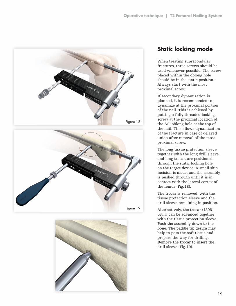
When treating supracondylar frac tures, three screws should be used whenever possible . The screw placed within the oblong hole should be in the static position . Always start with the most proximal screw .
If secondary dynamization is planned, it is recommended to dynamize at the proximal portion of the nail . This is achieved by putting a fully threaded locking screw at the proxi mal location of the A/P oblong hole at the top of the nail . This allows dynamization of the fracture in case of delayed union after removal of the most proximal screw .
The long tissue protection sleeve together with the long drill sleeve and long trocar, are positioned through the static locking hole on the target device . A small skin incision is made, and the assembly is pushed through until it is in contact with the lateral cortex of the femur (Fig . 18) .
The trocar is removed, with the tissue protection sleeve and the drill sleeve remaining in position .
Alternatively, the trocar (1806-0311) can be advanced together with the tissue protection sleeve . Push the assembly down to the bone . The paddle tip design may help to pass the soft tissue and prepare the way for drilling . Remove the trocar to insert the drill sleeve (Fig . 19) .
Figure 18
Figure 19
20
T2 Femoral Nailing System | Operative technique
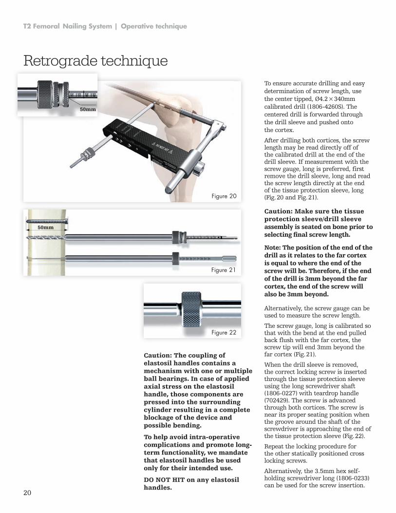
To ensure accurate drilling and easy determination of screw length, use the center tipped, Ø4 .2 × 340mm calibrated drill (1806-4260S). The centered drill is forwarded through the drill sleeve and pushed onto the cortex .
After drilling both cortices, the screw length may be read directly off of the calibrated drill at the end of the drill sleeve . If measurement with the screw gauge, long is preferred, first remove the drill sleeve, long and read the screw length directly at the end of the tissue protection sleeve, long (Fig . 20 and Fig . 21) .
Caution: Make sure the tissue protection sleeve/drill sleeve assembly is seated on bone prior to selecting final screw length.
Note: The position of the end of the drill as it relates to the far cortex is equal to where the end of the screw will be. Therefore, if the end of the drill is 3mm beyond the far cortex, the end of the screw will also be 3mm beyond.
50mm
50mm
Figure 20
Figure 21
Figure 22
Caution: The coupling of elastosil handles contains a mechanism with one or multiple ball bearings. In case of applied axial stress on the elastosil handle, those components are pressed into the surrounding cylinder resulting in a complete blockage of the device and possible bending.
To help avoid intra-operative complications and promote long-term functionality, we mandate that elastosil handles be used only for their intended use.
DO NOT HIT on any elastosil handles.
Retrograde technique
Alternatively, the screw gauge can be used to measure the screw length .
The screw gauge, long is calibrated so that with the bend at the end pulled back flush with the far cortex, the screw tip will end 3mm beyond the far cortex (Fig . 21) .
When the drill sleeve is removed, the correct locking screw is inserted through the tissue protection sleeve using the long screwdriver shaft (1806-0227) with teardrop handle (702429) . The screw is advanced through both cortices . The screw is near its proper seating position when the groove around the shaft of the screwdriver is approach ing the end of the tissue protection sleeve (Fig . 22) .
Repeat the locking procedure for the other statically positioned cross locking screws .
Alternatively, the 3.5mm hex self-holding screwdriver long (1806-0233) can be used for the screw insertion .
21
Operative technique | T2 Femoral Nailing System
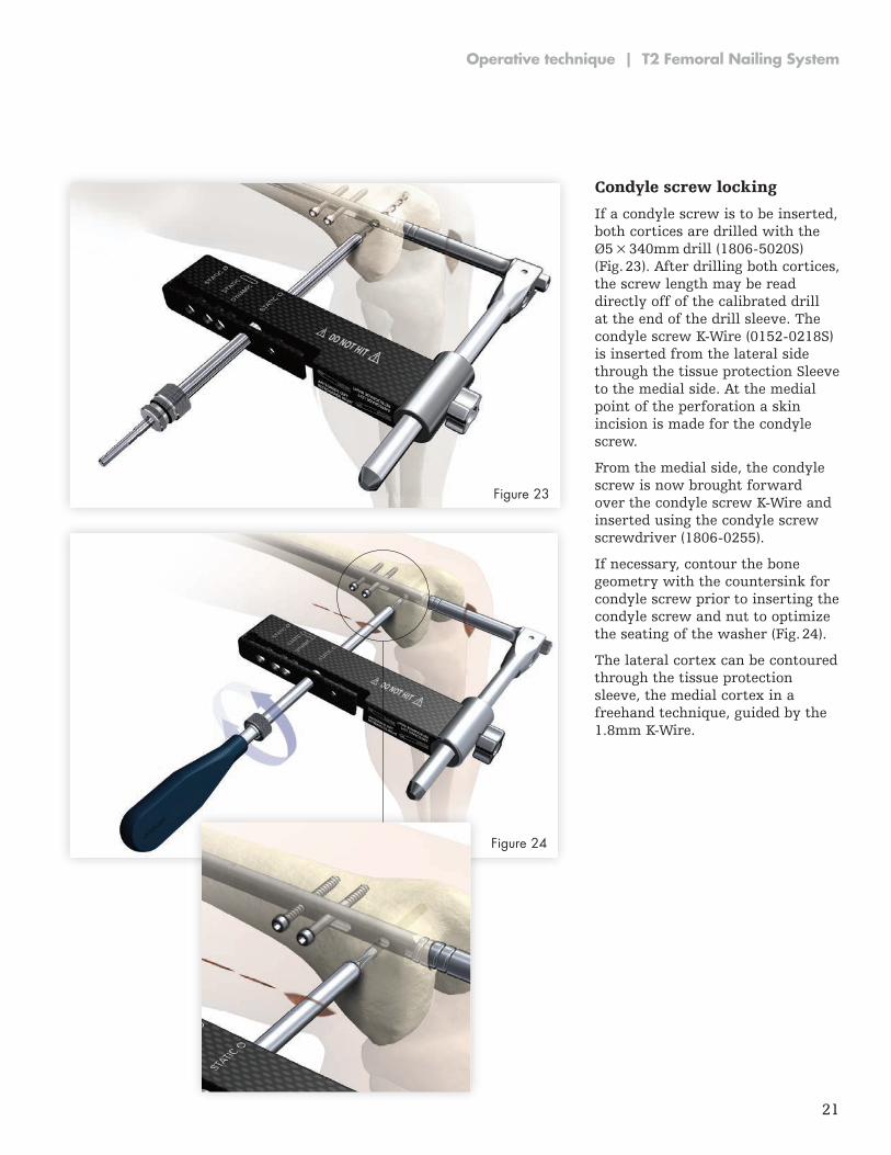
Condyle screw locking
If a condyle screw is to be inserted, both cortices are drilled with the Ø5 × 340mm drill (1806-5020S) (Fig . 23) . After drilling both cortices, the screw length may be read directly off of the calibrated drill at the end of the drill sleeve . The condyle screw K-Wire (0152-0218S) is inserted from the lateral side through the tissue protection Sleeve to the medial side . At the medial point of the perforation a skin incision is made for the condyle screw .
From the medial side, the condyle screw is now brought forward over the condyle screw K-Wire and inserted using the condyle screw screwdriver (1806-0255).
If necessary, contour the bone geometry with the countersink for condyle screw prior to inserting the condyle screw and nut to optimize the seating of the washer (Fig . 24) .
The lateral cortex can be contoured through the tissue protection sleeve, the medial cortex in a freehand technique, guided by the 1.8mm K-Wire.
Fig. 24
Figure 23
Figure 24
22
T2 Femoral Nailing System | Operative technique
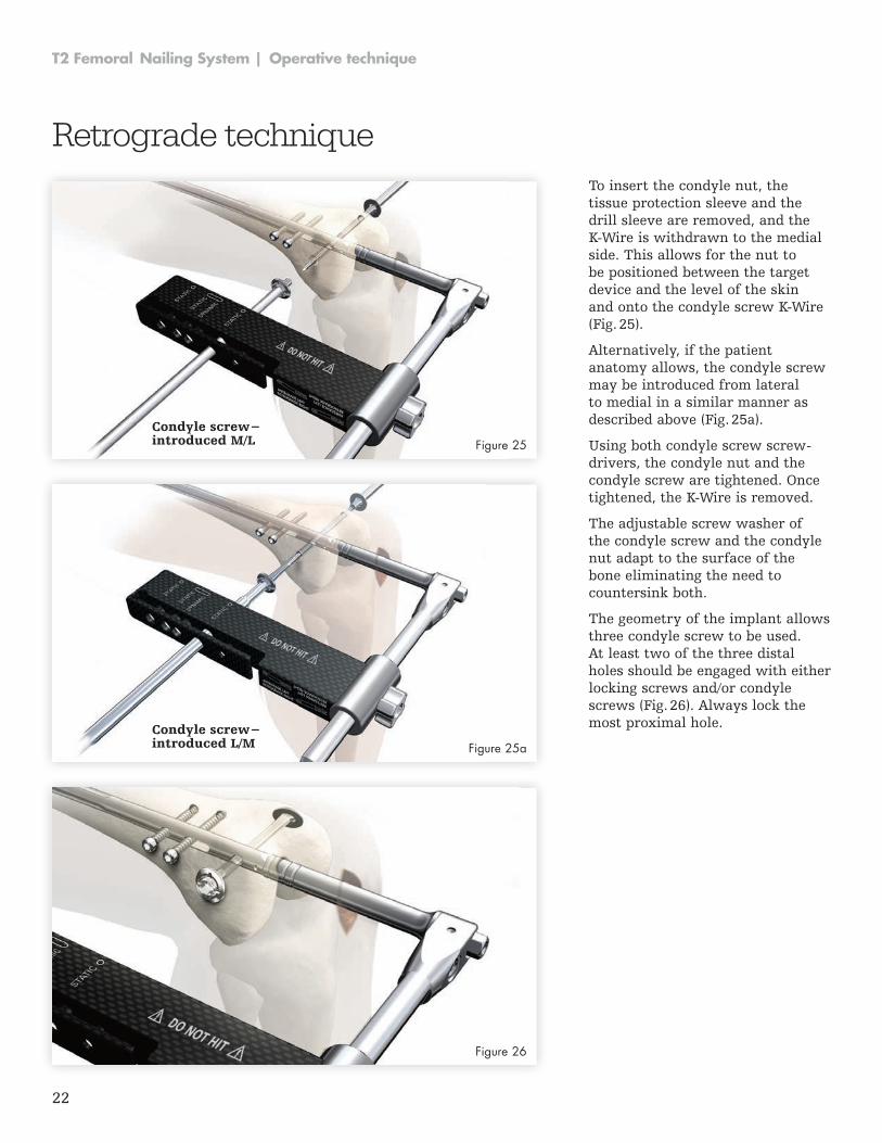
To insert the condyle nut, the tissue protection sleeve and the drill sleeve are removed, and the K-Wire is withdrawn to the medial side . This allows for the nut to be positioned between the target device and the level of the skin and onto the condyle screw K-Wire (Fig . 25) .
Alternatively, if the patient anatomy allows, the condyle screw may be introduced from lateral to medial in a similar manner as described above (Fig . 25a) .
Using both condyle screw screw-drivers, the condyle nut and the condyle screw are tightened . Once tightened, the K-Wire is removed.
The adjustable screw washer of the condyle screw and the condyle nut adapt to the surface of the bone eliminating the need to countersink both .
The geometry of the implant allows three condyle screw to be used . At least two of the three distal holes should be engaged with either locking screws and/or condyle screws (Fig . 26) . Always lock the most proximal hole .
Retrograde technique
Condyle screw−introduced L/M
Condyle screw−introduced M/L Figure 25
Figure 25a
Figure 26
23
Operative technique | T2 Femoral Nailing System
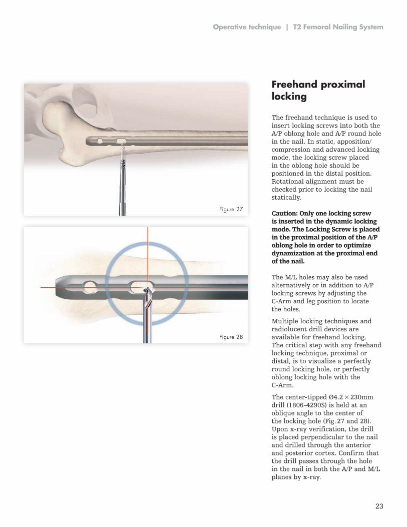
Freehand proximal locking The freehand technique is used to insert locking screws into both the A/P oblong hole and A/P round hole in the nail . In static, apposition/compression and advanced locking mode, the locking screw placed in the oblong hole should be positioned in the distal position . Rotational alignment must be checked prior to locking the nail statically .
Caution: Only one locking screw is inserted in the dynamic locking mode. The Locking Screw is placed in the proximal position of the A/P oblong hole in order to optimize dynamization at the proximal end of the nail.
The M/L holes may also be used alternatively or in addition to A/P locking screws by adjusting the C-Arm and leg position to locate the holes .
Multiple locking techniques and radiolucent drill devices are available for freehand locking . The critical step with any freehand locking technique, proximal or distal, is to visualize a perfectly round locking hole, or perfectly oblong locking hole with the C-Arm.
The center-tipped Ø4.2 × 230mm drill (1806-4290S) is held at an oblique angle to the center of the locking hole (Fig . 27 and 28) . Upon x-ray verification, the drill is placed perpendicular to the nail and drilled through the anterior and posterior cortex . Confirm that the drill passes through the hole in the nail in both the A/P and M/L planes by x-ray.
Figure 27
Figure 28
24
T2 Femoral Nailing System | Operative technique
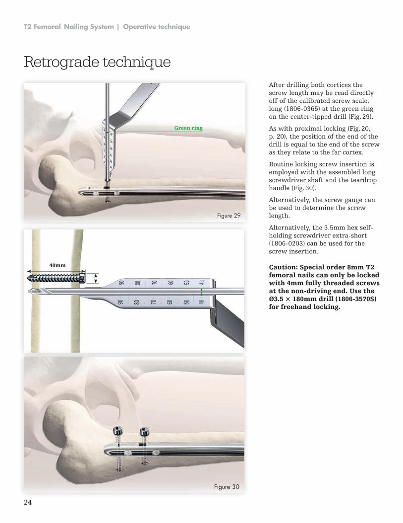
After drilling both cortices the screw length may be read directly off of the calibrated screw scale, long (1806-0365) at the green ring on the center-tipped drill (Fig. 29).
As with proximal locking (Fig . 20, p . 20), the position of the end of the drill is equal to the end of the screw as they relate to the far cortex .
Routine locking screw insertion is employed with the assembled long screwdriver shaft and the teardrop handle (Fig . 30) .
Alternatively, the screw gauge can be used to determine the screw length .
Alternatively, the 3.5mm hex self-holding screwdriver extra-short (1806-0203) can be used for the screw insertion .
Caution: Special order 8mm T2 femoral nails can only be locked with 4mm fully threaded screws at the non-driving end. Use the Ø3.5 × 180mm drill (1806-3570S) for freehand locking.
Retrograde technique
40mm
Figure 30
Green ring
Figure 29
25
Operative technique | T2 Femoral Nailing System
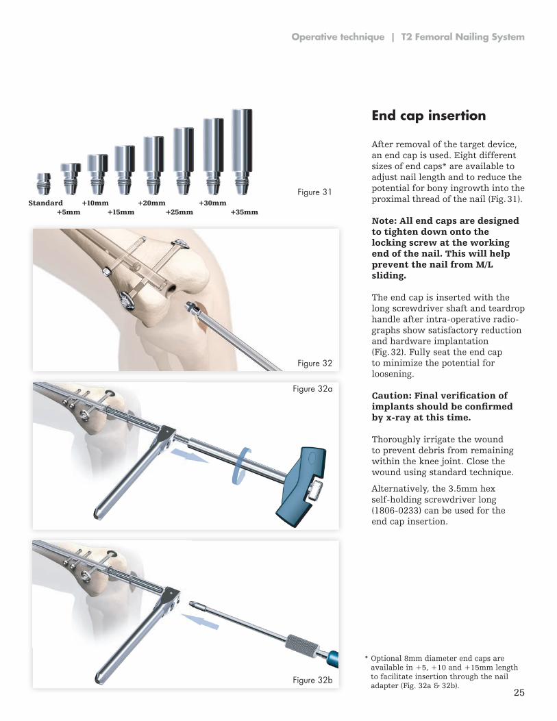
End cap insertion After removal of the target device, an end cap is used . Eight different sizes of end caps* are available to adjust nail length and to reduce the potential for bony ingrowth into the proximal thread of the nail (Fig . 31) .
Note: All end caps are designed to tighten down onto the locking screw at the working end of the nail. This will help prevent the nail from M/L sliding.
Caution: Final verification of implants should be confirmed by x-ray at this time.
The end cap is inserted with the long screwdriver shaft and teardrop handle after intra-operative radio-graphs show satisfactory reduction and hardware implantation (Fig . 32) . Fully seat the end cap to minimize the potential for loosening .
Thoroughly irrigate the wound to prevent debris from remaining within the knee joint . Close the wound using standard technique .
Alternatively, the 3 .5mm hex self-holding screwdriver long (1806-0233) can be used for the end cap insertion .
Standard +10mm +20mm +30mm +5mm +15mm +25mm +35mm
Figure 32
Figure 31
Figure 32a
Figure 32b
* Optional 8mm diameter end caps are available in +5, +10 and +15mm length to facilitate insertion through the nail adapter (Fig . 32a & 32b) .
26
T2 Femoral Nailing System | Operative technique
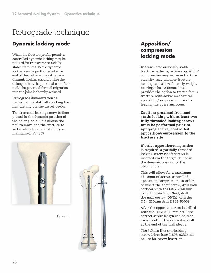
Dynamic locking mode When the fracture profile permits, controlled dynamic locking may be utilized for transverse or axially stable fractures. While dynamic locking can be performed at either end of the nail, routine retrograde dynamic locking should utilize the oblong hole at the proximal end of the nail . The potential for nail migration into the joint is thereby reduced .
Retrograde dynamization is performed by statically locking the nail distally via the target device .
The freehand locking screw is then placed in the dynamic position of the oblong hole . This allows the nail to move and the fracture to settle while torsional stability is maintained (Fig . 33) .
Apposition/compression locking mode In transverse or axially stable fracture patterns, active apposition/compression may increase fracture stability, may enhance fracture healing, and allow for early weight bearing . The T2 femoral nail provides the option to treat a femur fracture with active mechanical apposition/compression prior to leaving the operating room .
Caution: proximal freehand static locking with at least two fully threaded locking screws must be performed prior to applying active, controlled apposition/compression to the fracture site.
Retrograde technique
If active apposition/compression is required, a partially threaded locking screw (shaft screw) is inserted via the target device in the dynamic position of the oblong hole .
This will allow for a maximum of 10mm of active, controlled apposition/compression . In order to insert the shaft screw, drill both cortices with the Ø4 .2 × 340mm drill (1806-4260S). Next, drill the near cortex, ONLY, with the Ø5 × 230mm drill (1806-5000S).
After the opposite cortex is drilled with the Ø4 .2 × 340mm drill, the correct screw length can be read directly off of the calibrated drill at the end of the drill sleeve .
The 3.5mm Hex self-holding screwdriver long (1806-0233) can be use for screw insertion .
Figure 33
27
Operative technique | T2 Femoral Nailing System
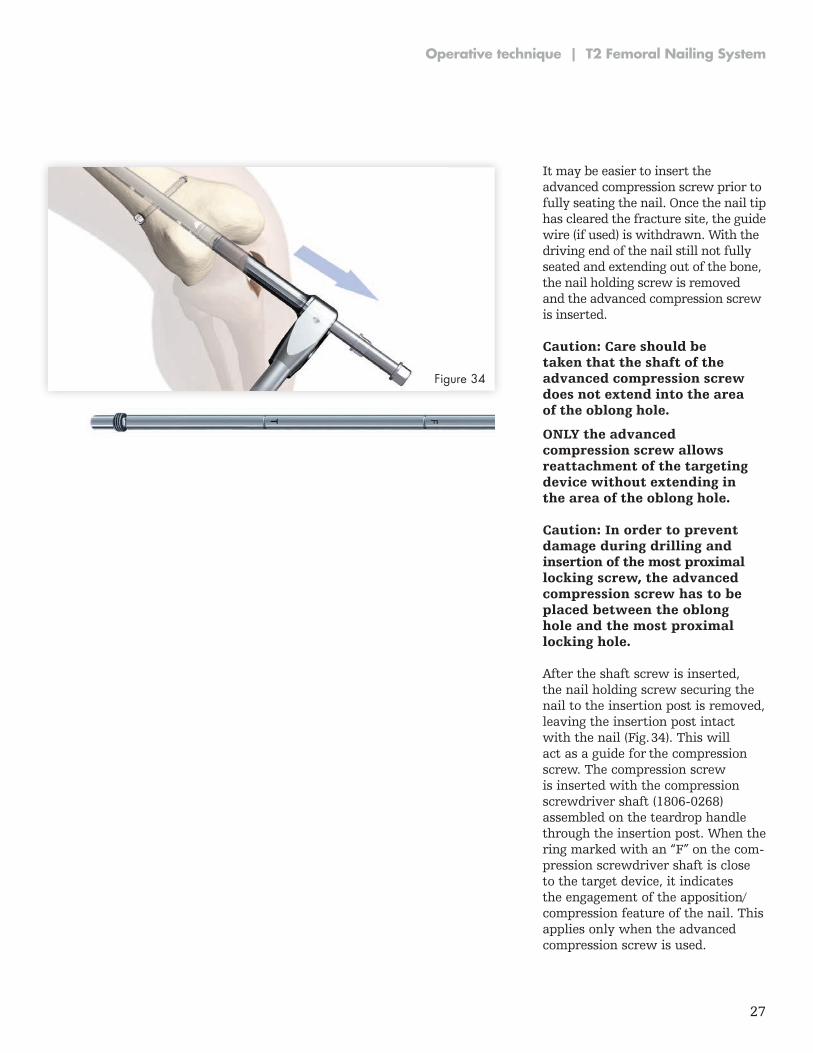
After the shaft screw is inserted, the nail holding screw securing the nail to the insertion post is removed, leaving the insertion post intact with the nail (Fig . 34) . This will act as a guide for the compression screw . The compres sion screw is inserted with the compression screwdriver shaft (1806-0268) assembled on the teardrop handle through the insertion post. When the ring marked with an “F” on the com-pression screwdriver shaft is close to the target device, it indicates the engagement of the apposition/compression feature of the nail . This applies only when the advanced compression screw is used .
Caution: Care should be taken that the shaft of the advanced compression screw does not extend into the area of the oblong hole.
ONLY the advanced compression screw allows reattachment of the targeting device without extending in the area of the oblong hole.
Caution: In order to prevent damage during drilling and insertion of the most proximal locking screw, the advanced compression screw has to be placed between the oblong hole and the most proximal locking hole.
Figure 34
It may be easier to insert the advanced compression screw prior to fully seating the nail . Once the nail tip has cleared the fracture site, the guide wire (if used) is withdrawn. With the driving end of the nail still not fully seated and extending out of the bone, the nail holding screw is removed and the advanced compression screw is inserted .
28
T2 Femoral Nailing System | Operative technique
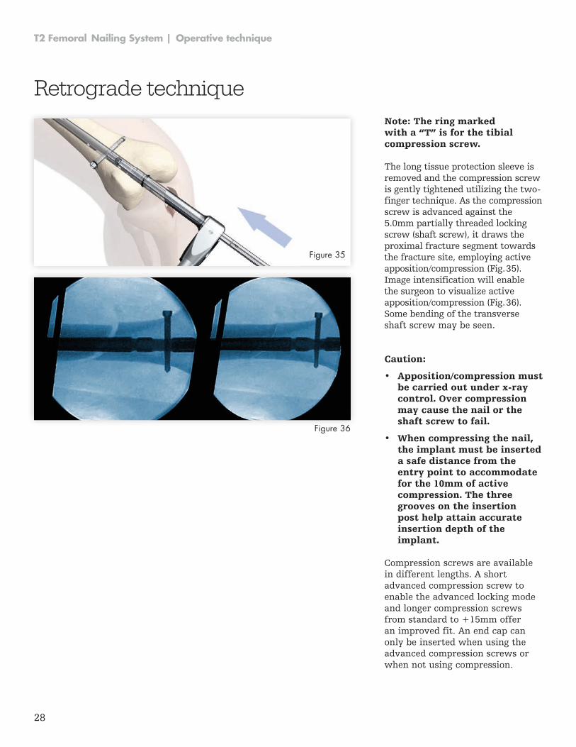
Caution:
• Apposition/compression must be carried out under x-ray control. Over compression may cause the nail or the shaft screw to fail.
• When compressing the nail, the implant must be inserted a safe distance from the entry point to accommodate for the 10mm of active compression. The three grooves on the insertion post help attain accurate insertion depth of the implant.
Note: The ring marked with a “T” is for the tibial compression screw.
The long tissue protection sleeve is removed and the compression screw is gently tightened utilizing the two-finger technique . As the compression screw is advanced against the 5 .0mm partially threaded locking screw (shaft screw), it draws the proximal fracture segment towards the fracture site, employing active apposition/compression (Fig . 35) . Image intensification will enable the surgeon to visualize active apposition/compression (Fig . 36) . Some bending of the transverse shaft screw may be seen .
Figure 35
Figure 36
Compression screws are available in different lengths . A short advanced compression screw to enable the advanced locking mode and longer compression screws from standard to +15mm offer an improved fit . An end cap can only be inserted when using the advanced compression screws or when not using compression .
Retrograde technique
29
Operative technique | T2 Femoral Nailing System
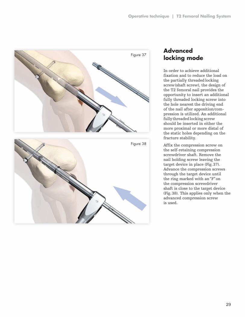
Advanced locking mode
In order to achieve additional fixation and to reduce the load on the partially threaded locking screw (shaft screw), the design of the T2 femoral nail provides the opportunity to insert an additional fully threaded lock ing screw into the hole nearest the driving end of the nail after apposition/com-pression is utilized . An additional fully threaded locking screw should be inserted in either the more proxi mal or more distal of the static holes depending on the fracture stability .
Affix the compression screw on the self-retaining compression screwdriver shaft . Remove the nail holding screw leaving the target device in place (Fig . 37) . Advance the compression screws through the target device until the ring marked with an “F” on the compression screwdriver shaft is close to the target device (Fig . 38) . This applies only when the advanced compression screw is used .
Figure 37
Figure 38
30
T2 Femoral Nailing System | Operative technique
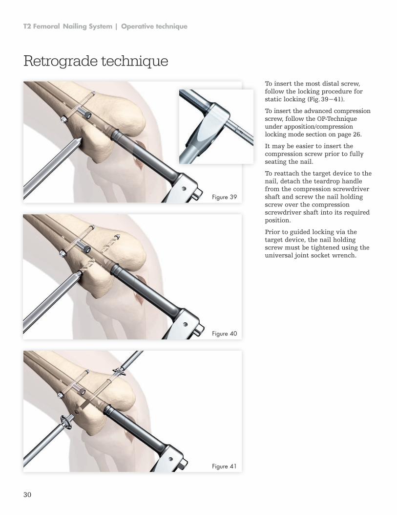
To insert the most distal screw, follow the locking procedure for static locking (Fig. 39−41).
To insert the advanced compression screw, follow the OP-Tech nique under apposition/compression locking mode section on page 26 .
It may be easier to insert the compression screw prior to fully seating the nail .
To reattach the target device to the nail, detach the teardrop handle from the compression screwdriver shaft and screw the nail holding screw over the compression screwdriver shaft into its required position .
Prior to guided locking via the target device, the nail holding screw must be tightened using the universal joint socket wrench .
Retrograde technique
Figure 39
Figure 40
Figure 41
31
Operative technique | T2 Femoral Nailing System
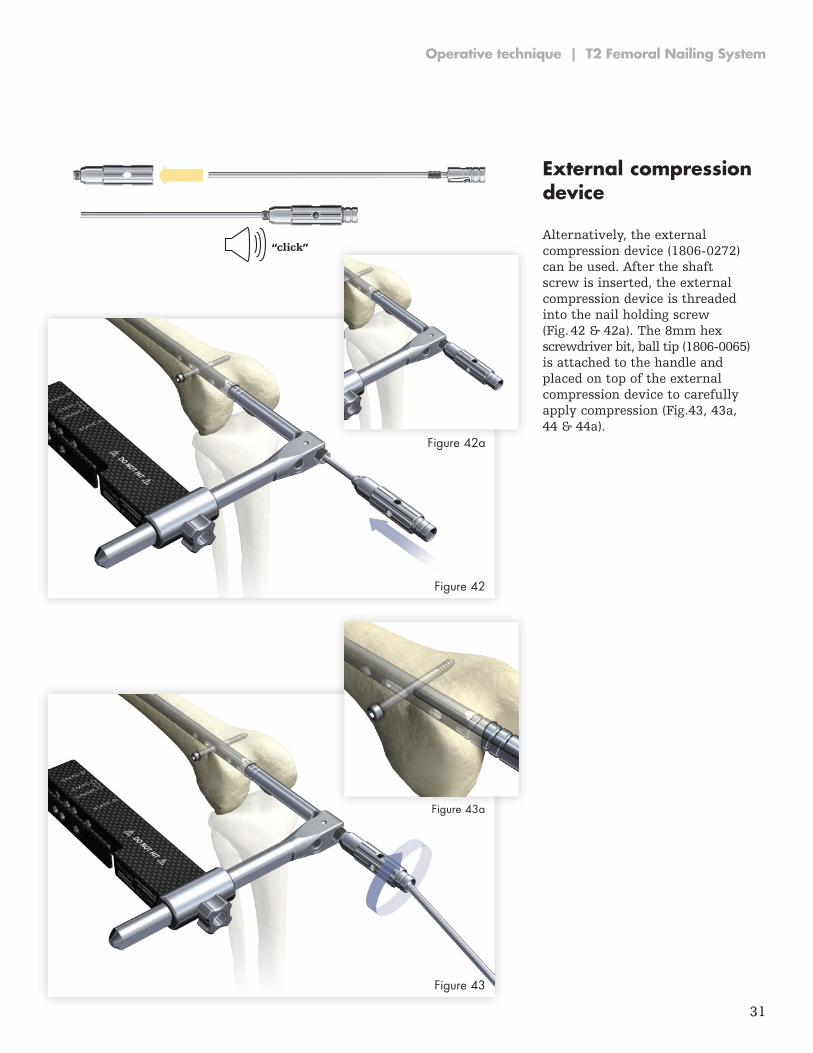
External compression device
Alternatively, the external compression device (1806-0272) can be used . After the shaft screw is inserted, the external compression device is threaded into the nail holding screw (Fig . 42 & 42a) . The 8mm hex screwdriver bit, ball tip (1806-0065) is attached to the handle and placed on top of the external compression device to carefully apply compression (Fig .43, 43a, 44 & 44a) .
“click”
Figure 42a
Figure 43a
Figure 42
Figure 43
32
T2 Femoral Nailing System | Operative technique
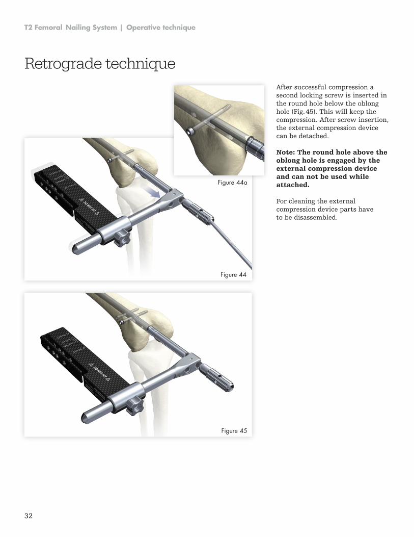
After successful compression a second locking screw is inserted in the round hole below the oblong hole (Fig . 45) . This will keep the compression . After screw insertion, the external compression device can be detached .
Retrograde technique
Figure 44
Figure 45
Figure 44a
Note: The round hole above the oblong hole is engaged by the external compression device and can not be used while attached.
For cleaning the external compression device parts have to be disassembled .
33
Operative technique | T2 Femoral Nailing System
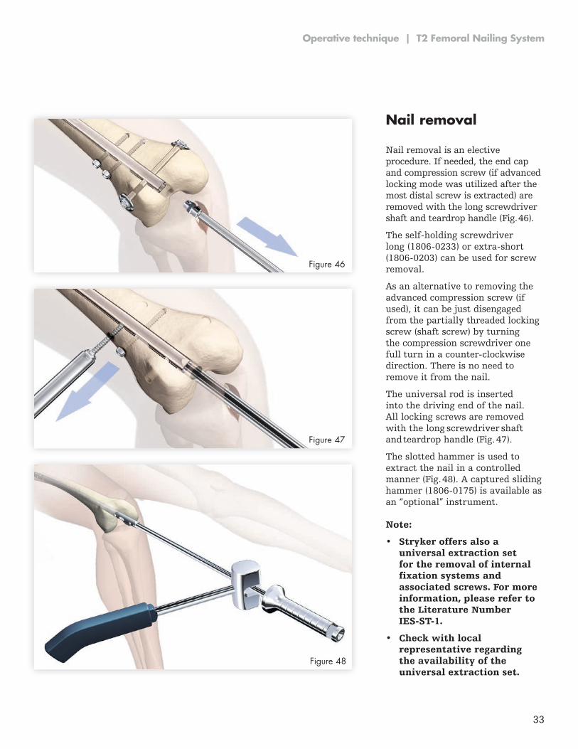
Nail removal Nail removal is an elective procedure . If needed, the end cap and compres sion screw (if advanced locking mode was utilized after the most distal screw is extracted) are removed with the long screwdriver shaft and teardrop handle (Fig . 46) .
The self-holding screwdriver long (1806-0233) or extra-short (1806-0203) can be used for screw removal .
As an alternative to removing the advanced compression screw (if used), it can be just disengaged from the partially threaded locking screw (shaft screw) by turning the compression screwdriver one full turn in a counter-clockwise direction . There is no need to remove it from the nail .
The universal rod is inserted into the driving end of the nail . All locking screws are removed with the long screwdriver shaft and teardrop handle (Fig . 47) .
The slotted hammer is used to extract the nail in a controlled manner (Fig . 48) . A captured sliding hammer (1806-0175) is available as an “optional” instrument .
Figure 46
Figure 47
Figure 48
Note:
• Stryker offers also a universal extraction set for the removal of internal fixation systems and associated screws. For more information, please refer to the Literature Number IES-ST-1.
• Check with local representative regarding the availability of the universal extraction set.
34
T2 Femoral Nailing System | Operative technique
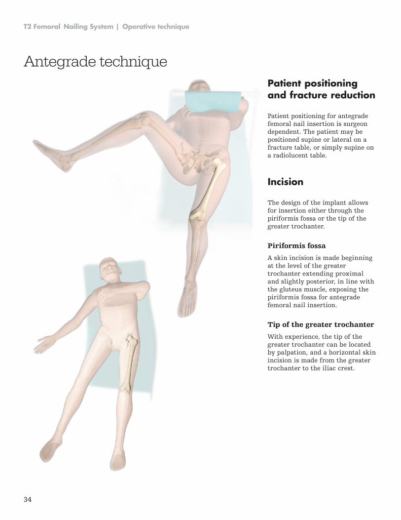
Patient positioning and fracture reduction
Patient positioning for antegrade femoral nail insertion is surgeon dependent . The patient may be positioned supine or lateral on a fracture table, or simply supine on a radiolucent table .
Incision
The design of the implant allows for insertion either through the piriformis fossa or the tip of the greater trochanter .
Piriformis fossa
A skin incision is made beginning at the level of the greater tro chanter extending proximal and slightly posterior, in line with the gluteus muscle, exposing the piriformis fossa for antegrade femoral nail insertion .
Tip of the greater trochanter
With experience, the tip of the greater trochanter can be located by palpation, and a horizontal skin incision is made from the greater trochanter to the iliac crest .
Antegrade technique
35
Operative technique | T2 Femoral Nailing System
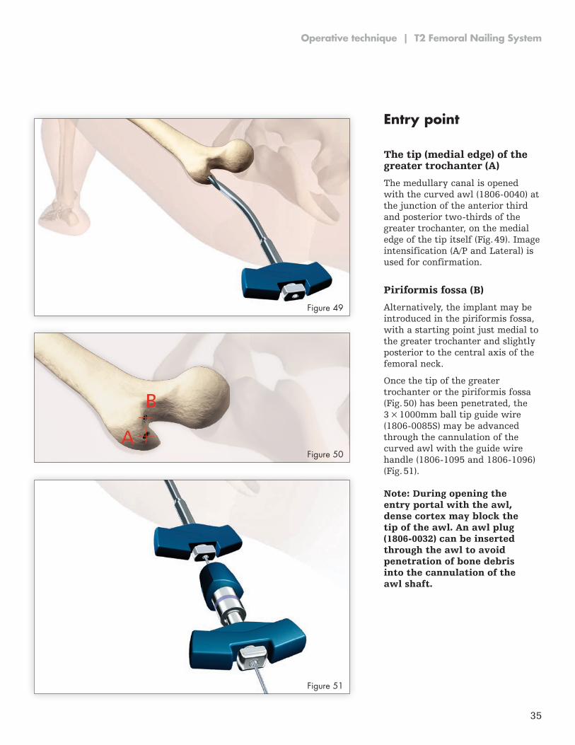
Entry point
The tip (medial edge) of the greater trochanter (A)
The medullary canal is opened with the curved awl (1806-0040) at the junction of the anterior third and pos terior two-thirds of the greater trochanter, on the medial edge of the tip itself (Fig . 49) . Image intensifica tion (A/P and Lateral) is used for confirmation .
Piriformis fossa (B)
Alternatively, the implant may be introduced in the piriformis fossa, with a starting point just medial to the greater trochanter and slightly posterior to the central axis of the femoral neck .
Once the tip of the greater trochanter or the piriformis fossa (Fig . 50) has been penetrated, the 3 × 1000mm ball tip guide wire (1806-0085S) may be advanced through the cannulation of the curved awl with the guide wire handle (1806-1095 and 1806-1096) (Fig . 51) .
Note: During opening the entry portal with the awl, dense cortex may block the tip of the awl. An awl plug (1806-0032) can be inserted through the awl to avoid penetration of bone debris into the cannulation of the awl shaft.
Figure 49
Figure 50
Figure 51
36
T2 Femoral Nailing System | Operative technique
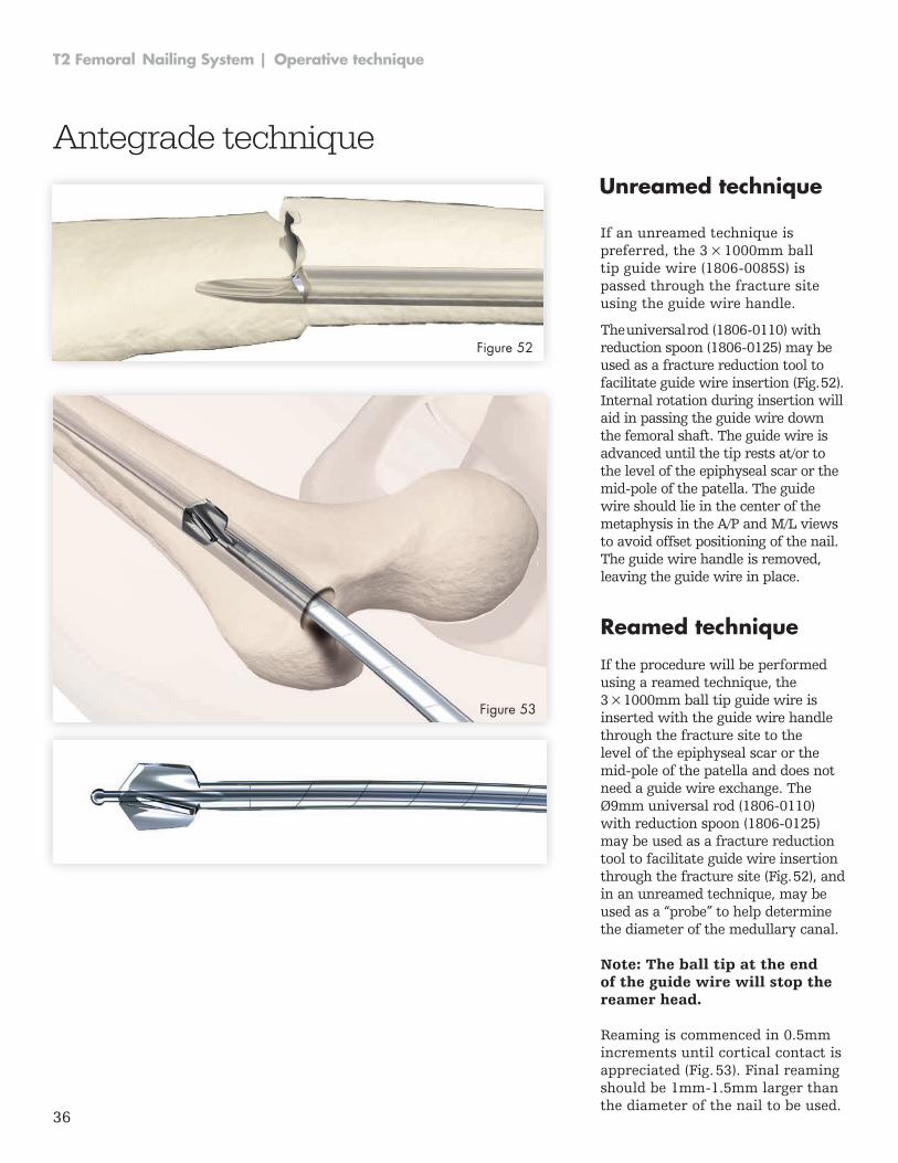
Unreamed technique
If an unreamed technique is preferred, the 3 × 1000mm ball tip guide wire (1806-0085S) is passed through the fracture site using the guide wire handle .
The universal rod (1806-0110) with reduction spoon (1806-0125) may be used as a fracture reduction tool to facilitate guide wire insertion (Fig . 52) . Internal rotation during insertion will aid in passing the guide wire down the femoral shaft . The guide wire is advanced until the tip rests at/or to the level of the epiphyseal scar or the mid-pole of the patella. The guide wire should lie in the center of the metaphysis in the A/P and M/L views to avoid offset positioning of the nail . The guide wire handle is removed, leaving the guide wire in place .
Reamed technique
If the procedure will be performed using a reamed technique, the 3 × 1000mm ball tip guide wire is inserted with the guide wire handle through the fracture site to the level of the epiphyseal scar or the mid-pole of the patella and does not need a guide wire exchange . The Ø9mm universal rod (1806-0110) with reduction spoon (1806-0125) may be used as a fracture reduction tool to facilitate guide wire insertion through the fracture site (Fig . 52), and in an unreamed technique, may be used as a “probe” to help determine the diameter of the medullary canal .
Note: The ball tip at the end of the guide wire will stop the reamer head.
Reaming is commenced in 0 .5mm increments until cortical contact is appreciated (Fig . 53) . Final reaming should be 1mm-1.5mm larger than the diam eter of the nail to be used .
Figure 52
Figure 53
Antegrade technique
37
Operative technique | T2 Femoral Nailing System
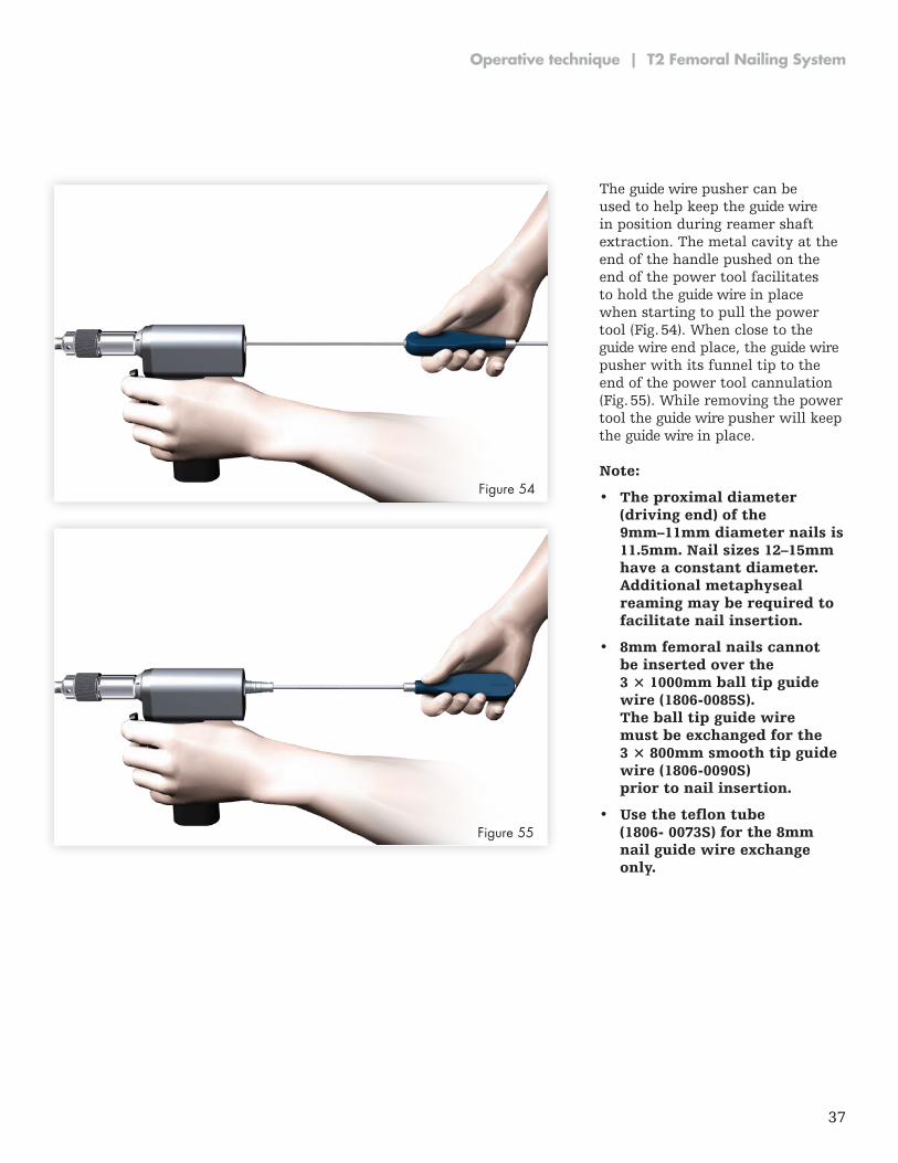
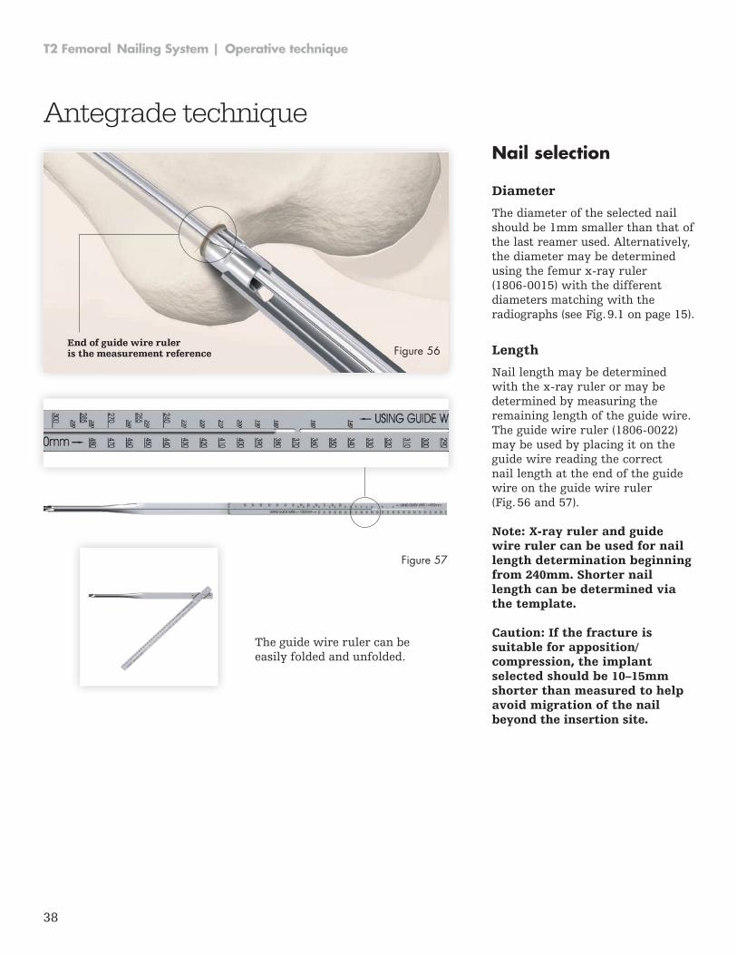
The guide wire pusher can be used to help keep the guide wire in position during reamer shaft extraction . The metal cavity at the end of the handle pushed on the end of the power tool facilitates to hold the guide wire in place when starting to pull the power tool (Fig. 54). When close to the guide wire end place, the guide wire pusher with its funnel tip to the end of the power tool cannulation (Fig. 55). While removing the power tool the guide wire pusher will keep the guide wire in place .
Figure 54
Figure 55
Note:
• The proximal diameter (driving end) of the 9mm–11mm diameter nails is 11.5mm. Nail sizes 12–15mm have a constant diameter. Additional metaphyseal reaming may be required to facilitate nail insertion.
• 8mm femoral nails cannot be inserted over the 3 × 1000mm ball tip guide wire (1806-0085S). The ball tip guide wire must be exchanged for the 3 × 800mm smooth tip guide wire (1806-0090S) prior to nail insertion.
• Use the teflon tube (1806- 0073S) for the 8mm nail guide wire exchange only.
38
T2 Femoral Nailing System | Operative technique
Nail selection
Diameter
The diameter of the selected nail should be 1mm smaller than that of the last reamer used . Alternatively, the diameter may be determined using the femur x-ray ruler (1806-0015) with the different diameters matching with the radiographs (see Fig . 9 .1 on page 15) .
Length
Nail length may be determined with the x-ray ruler or may be determined by measuring the remaining length of the guide wire . The guide wire ruler (1806-0022) may be used by placing it on the guide wire reading the correct nail length at the end of the guide wire on the guide wire ruler (Fig . 56 and 57) .
Note: X-ray ruler and guide wire ruler can be used for nail length determination beginning from 240mm. Shorter nail length can be determined via the template.
Caution: If the fracture is suitable for apposition/compression, the implant se lect ed should be 10–15mm shorter than measured to help avoid migration of the nail beyond the insertion site.
Antegrade technique
End of guide wire ruleris the measurement reference
The guide wire ruler can be easily folded and unfolded .
Figure 56
Figure 57
39
Operative technique | T2 Femoral Nailing System
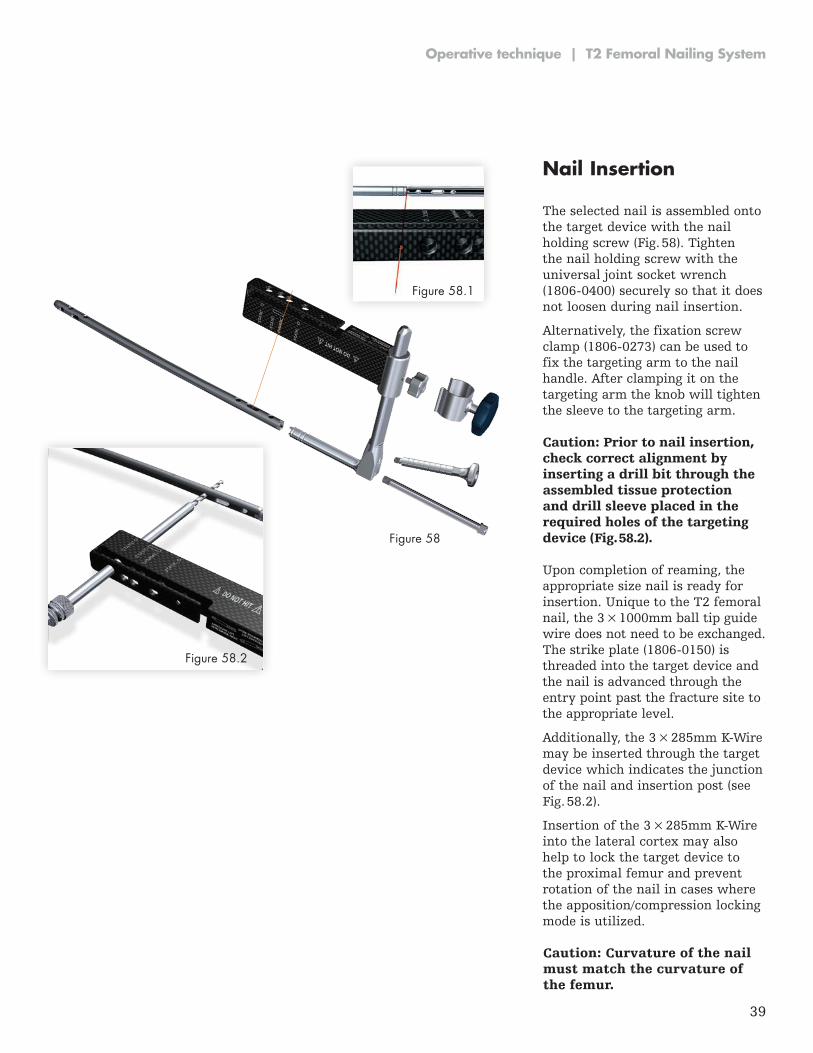
Caution: Prior to nail insertion, check correct alignment by inserting a drill bit through the assembled tissue protection and drill sleeve placed in the required holes of the targeting device (Fig. 58.2).
Nail Insertion
The selected nail is assembled onto the target device with the nail holding screw (Fig . 58) . Tighten the nail holding screw with the universal joint socket wrench (1806-0400) securely so that it does not loosen during nail insertion .
Alternatively, the fixation screw clamp (1806-0273) can be used to fix the targeting arm to the nail handle . After clamping it on the targeting arm the knob will tighten the sleeve to the targeting arm .
K-Wire
Upon completion of reaming, the appropriate size nail is ready for insertion . Unique to the T2 femoral nail, the 3 × 1000mm ball tip guide wire does not need to be exchanged . The strike plate (1806-0150) is threaded into the target device and the nail is advanced through the entry point past the fracture site to the appropriate level .
Additionally, the 3 × 285mm K-Wire may be inserted through the target device which indicates the junc tion of the nail and insertion post (see Fig . 58 .2) .
Insertion of the 3 × 285mm K-Wire into the lateral cortex may also help to lock the target device to the proximal femur and prevent rotation of the nail in cases where the apposition/compression locking mode is utilized .
Figure 58
Figure 58.2
Figure 58.1
Caution: Curvature of the nail must match the curvature of the femur.
40
T2 Femoral Nailing System | Operative technique
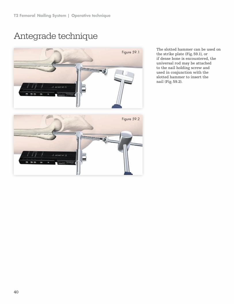
The slotted hammer can be used on the strike plate (Fig . 59 .1), or if dense bone is encountered, the universal rod may be attached to the nail holding screw and used in conjunc tion with the slotted hammer to insert the nail (Fig . 59 .2) .
Figure 59.1
Figure 59.2
Antegrade technique
41
Operative technique | T2 Femoral Nailing System
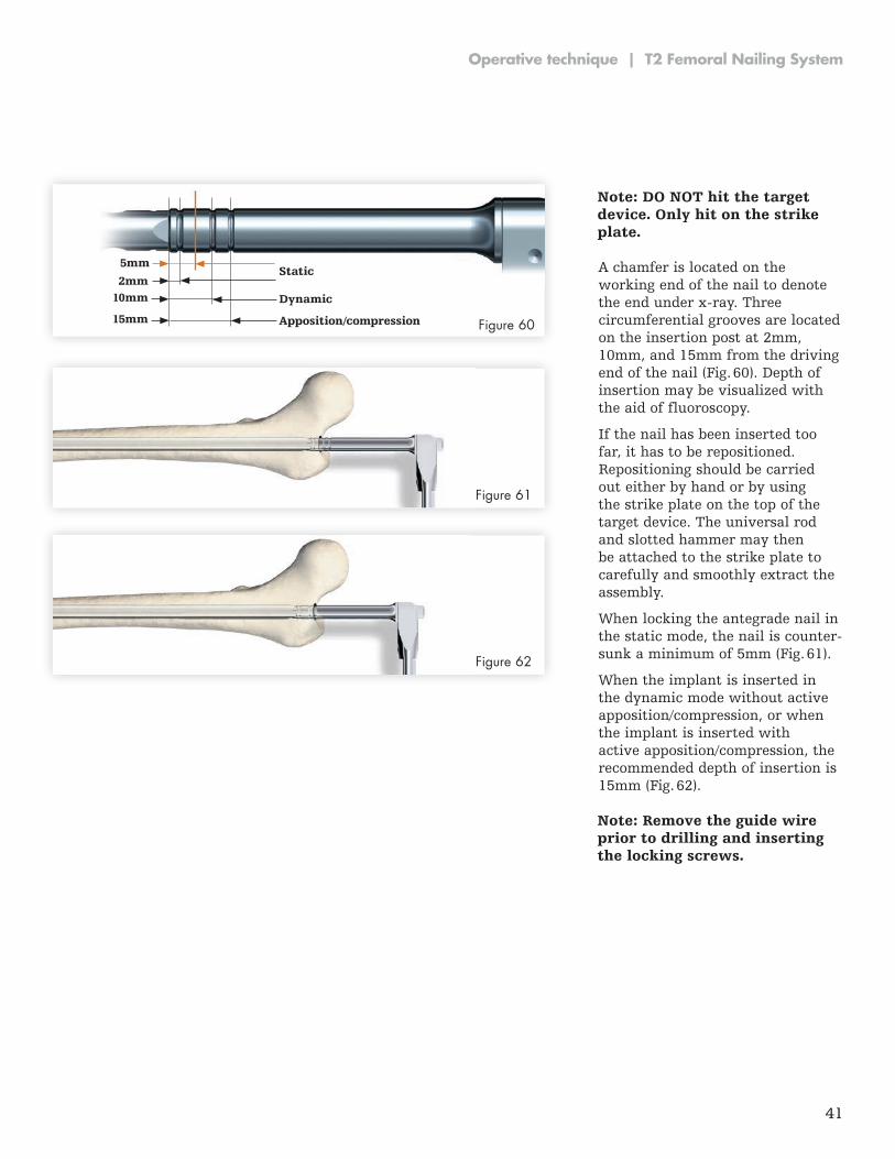
A chamfer is located on the working end of the nail to denote the end under x-ray. Three circumferential grooves are located on the insertion post at 2mm, 10mm, and 15mm from the driving end of the nail (Fig . 60) . Depth of insertion may be visualized with the aid of fluoroscopy .
If the nail has been inserted too far, it has to be repositioned . Repositioning should be carried out either by hand or by using the strike plate on the top of the target device . The universal rod and slotted hammer may then be attached to the strike plate to carefully and smoothly extract the assembly .
When locking the antegrade nail in the static mode, the nail is counter-sunk a minimum of 5mm (Fig . 61) .
When the implant is inserted in the dynamic mode without active apposition/compression, or when the implant is inserted with active apposition/compression, the recommended depth of insertion is 15mm (Fig . 62) .
10mm2mm
15mm
Static
Dynamic
Apposition/compression
5mm
Figure 60
Figure 61
Figure 62
Note: DO NOT hit the target device. Only hit on the strike plate.
Note: Remove the guide wire prior to drilling and inserting the locking screws.
42
T2 Femoral Nailing System | Operative technique
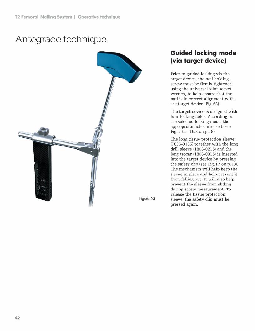
Guided locking mode (via target device)
Prior to guided locking via the target device, the nail holding screw must be firmly tightened using the universal joint socket wrench, to help ensure that the nail is in correct alignment with the target device (Fig . 63) .
The target device is designed with four locking holes . According to the selected locking mode, the appropri ate holes are used (see Fig . 16 .1 .–16 .3 on p .18) .
The long tissue protection sleeve (1806-0185) together with the long drill sleeve (1806-0215) and the long trocar (1806-0315) is inserted into the target device by pressing the safety clip (see Fig . 17 on p .18) . The mechanism will help keep the sleeve in place and help prevent it from falling out . It will also help prevent the sleeve from sliding during screw measurement . To release the tissue protection sleeve, the safety clip must be pressed again .
Figure 63
Antegrade technique
43
Operative technique | T2 Femoral Nailing System
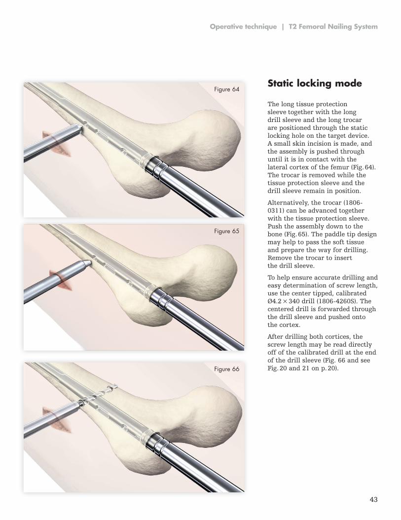
Static locking mode
The long tissue protection sleeve together with the long drill sleeve and the long trocar are positioned through the static locking hole on the target device . A small skin incision is made, and the assembly is pushed through until it is in contact with the lateral cortex of the femur (Fig . 64) . The trocar is removed while the tissue protection sleeve and the drill sleeve remain in position .
Alternatively, the trocar (1806-0311) can be advanced together with the tissue protection sleeve . Push the assembly down to the bone (Fig . 65) . The paddle tip design may help to pass the soft tissue and prepare the way for drilling . Remove the trocar to insert the drill sleeve .
To help ensure accurate drilling and easy determination of screw length, use the center tipped, calibrated Ø4.2 × 340 drill (1806-4260S). The centered drill is forwarded through the drill sleeve and pushed onto the cortex .
After drilling both cortices, the screw length may be read directly off of the calibrated drill at the end of the drill sleeve (Fig . 66 and see Fig . 20 and 21 on p . 20) .
Figure 64
Figure 65
Figure 66
44
T2 Femoral Nailing System | Operative technique
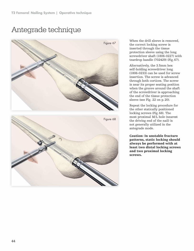
When the drill sleeve is removed, the correct locking screw is inserted through the tissue protection sleeve using the long screwdriver shaft (1806-0227) with teardrop handle (702429) (Fig . 67) .
Alternatively, the 3 .5mm hex self-holding screwdriver long (1806-0233) can be used for screw insertion . The screw is ad vanced through both cortices . The screw is near its proper seating position when the groove around the shaft of the screwdriver is ap proaching the end of the tissue pro tection sleeve (see Fig . 22 on p . 20) .
Repeat the locking procedure for the other statically positioned locking screws (Fig . 68) . The most proximal M/L hole (nearest the driving end of the nail) is not generally utilized in the antegrade mode .
Figure 67
Figure 68
Antegrade technique
Caution: In unstable fracture patterns, static locking should always be per formed with at least two distal locking screws and two proximal locking screws.
45
Operative technique | T2 Femoral Nailing System
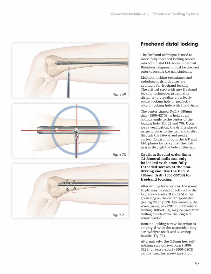
Freehand distal locking
The freehand technique is used to insert fully threaded locking screws into both distal M/L holes in the nail . Rotational alignment must be checked prior to locking the nail statically .
Multiple locking techniques and radiolucent drill devices are available for freehand locking . The critical step with any freehand locking tech nique, proximal or distal, is to visualize a perfectly round locking hole or perfectly oblong locking hole with the C-Arm.
The center-tipped Ø4.2 × 180mm drill (1806-4270S) is held at an oblique angle to the center of the locking hole (Fig . 69 and 70) . Upon x-ray verification, the drill is placed per pendicular to the nail and drilled through the lateral and medial cortex . Confirm in both the A/P and M/L planes by x-ray that the drill passes through the hole in the nail .
Figure 69
Figure 70
Figure 71
Caution: Special order 8mm T2 femoral nails can only be locked with 4mm fully threaded screws at the non-driving end. Use the Ø3.5 × 180mm drill (1806-3570S) for freehand locking.
After drilling both cortices, the screw length may be read directly off of the long screw scale (1806-0365) at the green ring on the center tipped drill (see Fig . 29 on p . 23) . Alternatively, the screw gauge, (20-120mm) for freehand locking (1806-0331), may be used after drilling to determine the length of screw needed .
Routine locking screw insertion is employed with the assembled long screwdriver shaft and teardrop handle (Fig . 71) .
Alternatively, the 3.5mm hex self-holding screwdriver long (1806-0233) or extra-short (1806-0203) can be used for screw insertion .
46
T2 Femoral Nailing System | Operative technique
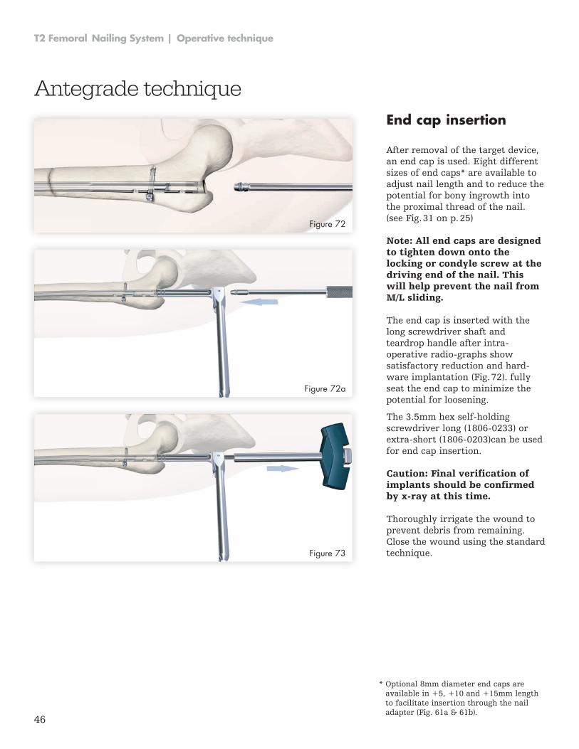
End cap insertion After removal of the target device, an end cap is used . Eight different sizes of end caps* are available to adjust nail length and to reduce the potential for bony ingrowth into the proximal thread of the nail . (see Fig . 31 on p . 25)
Antegrade technique
Note: All end caps are designed to tighten down onto the locking or condyle screw at the driving end of the nail. This will help prevent the nail from M/L sliding.
Caution: Final verification of implants should be confirmed by x-ray at this time.
The end cap is inserted with the long screwdriver shaft and teardrop han dle after intra-operative radio-graphs show satisfactory reduction and hard-ware implantation (Fig . 72) . fully seat the end cap to minimize the potential for loosening .
The 3.5mm hex self-holding screwdriver long (1806-0233) or extra-short (1806-0203)can be used for end cap insertion .
Thoroughly irrigate the wound to prevent debris from remaining . Close the wound using the standard technique .
Figure 72
Figure 72a
Figure 73
* Optional 8mm diameter end caps are available in +5, +10 and +15mm length to facilitate insertion through the nail adapter (Fig . 61a & 61b) .
47
Operative technique | T2 Femoral Nailing System
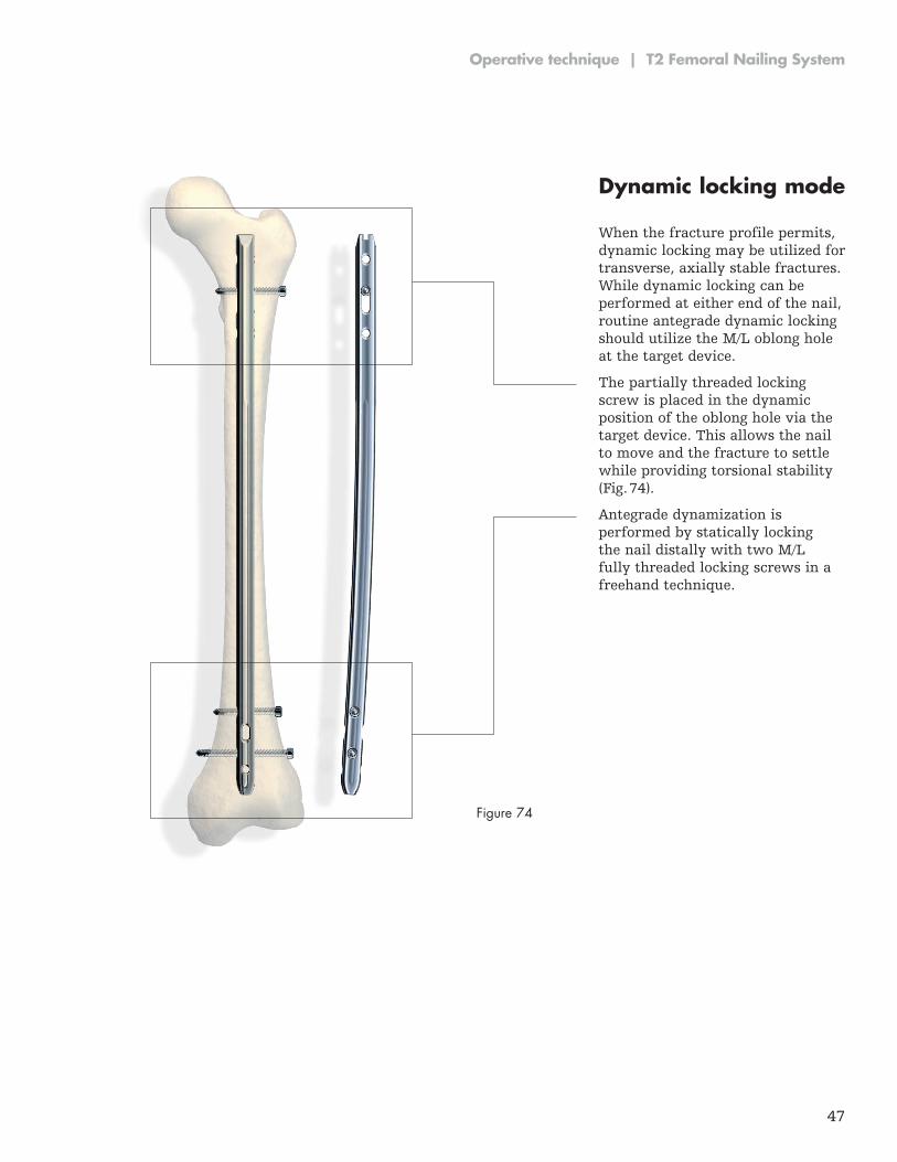
Dynamic locking mode When the fracture profile permits, dynamic locking may be utilized for transverse, axially stable fractures . While dynamic locking can be performed at either end of the nail, routine antegrade dynamic locking should utilize the M/L oblong hole at the target device .
The partially threaded locking screw is placed in the dynamic posi tion of the oblong hole via the target device . This allows the nail to move and the fracture to settle while provid ing torsional stability (Fig . 74) .
Antegrade dynamization is performed by statically locking the nail distally with two M/L fully threaded locking screws in a freehand technique .
Figure 74
48
T2 Femoral Nailing System | Operative technique
Apposition/compression locking mode In transverse, axially stable fracture patterns, active apposition/compres-sion increases fracture stability, may enhance fracture healing, and allow for early weight bearing . The T2 femoral nail gives the option to treat a femur fracture with active mechani cal apposition/compression prior to leaving the operating room .
Antegrade technique
Caution: Distal freehand static locking with at least two fully threaded locking screws must be per formed prior to applying active, control led apposition/compression to the fracture site.
If active apposition/compression is required, a partially threaded locking screw (shaft screw) is in serted via the target device in the dynamic position of the oblong hole .
This will allow for a maxi mum of 10mm of active, controlled ap po-sition/compression . In order to insert the shaft screw, drill both cortices with the Ø4.2 × 340mm drill (1806-4260S) . Next, drill the near cortex, ONLY, with the Ø5 × 230mm drill (1806-5000S).
After the opposite cortex is drilled with the Ø4 .2 × 340mm drill, the correct screw length can be read directly off of the calibrated drill at the end of the drill sleeve .
The 3.5mm hex self-holding screwdriver long (1806-0233) can be use for screw insertion .
It may be easier to insert the advanced compression screw prior to fully seating the nail . Once the nail tip has cleared the fracture site, the guide wire (if used) is withdrawn . With the driving end of the nail still not fully seated and extending out of the bone, the nail holding screw is removed and the advanced compression screw is inserted .
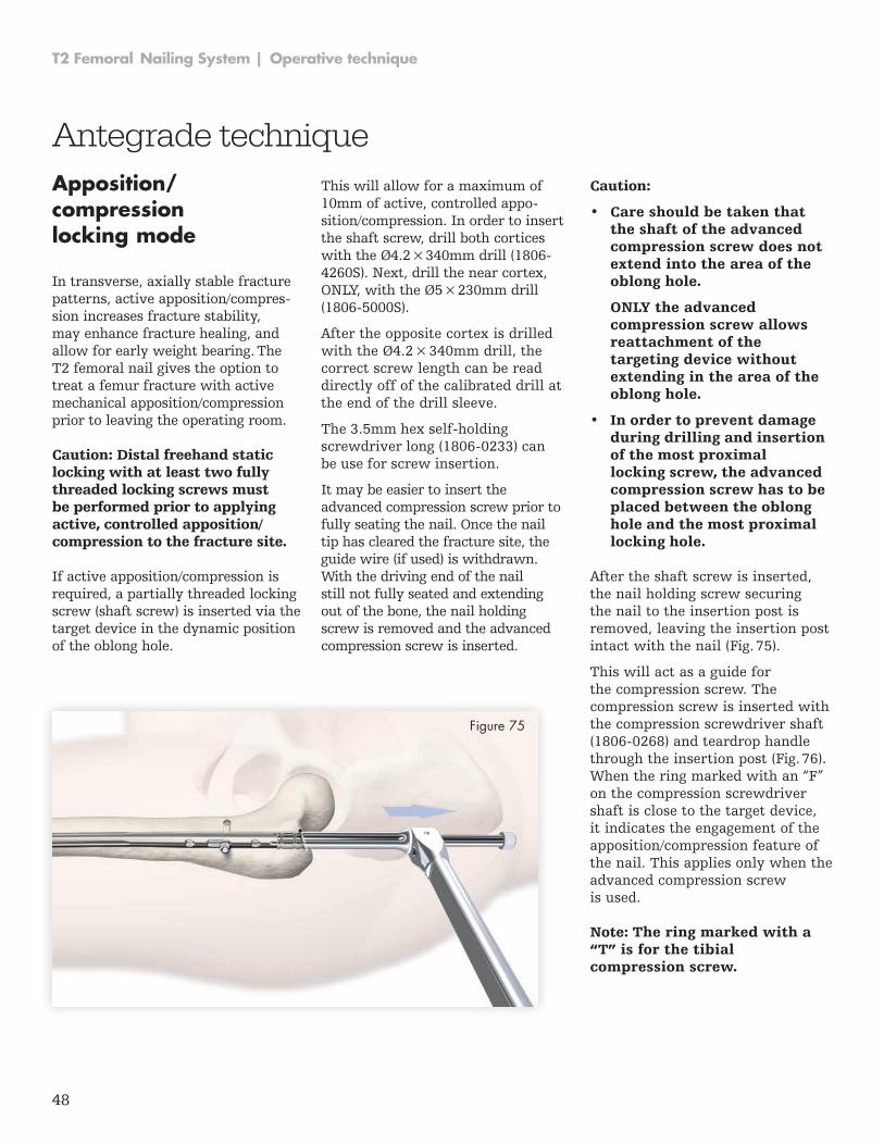
Figure 75
After the shaft screw is inserted, the nail holding screw securing the nail to the insertion post is removed, leaving the insertion post intact with the nail (Fig . 75) .
This will act as a guide for the compression screw . The compression screw is inserted with the compression screwdriver shaft (1806-0268) and teardrop handle through the insertion post (Fig . 76) . When the ring marked with an “F” on the compression screwdriver shaft is close to the target device, it indicates the engagement of the apposition/compression feature of the nail . This applies only when the advanced compression screw is used .
Caution:
• Care should be taken that the shaft of the advanced compression screw does not extend into the area of the oblong hole.
ONLY the advanced compression screw allows reattachment of the targeting device without extending in the area of the oblong hole.
• In order to prevent damage during drilling and insertion of the most proximal locking screw, the advanced compression screw has to be placed between the oblong hole and the most proximal locking hole.
Note: The ring marked with a “T” is for the tibial compression screw.
49
Operative technique | T2 Femoral Nailing System
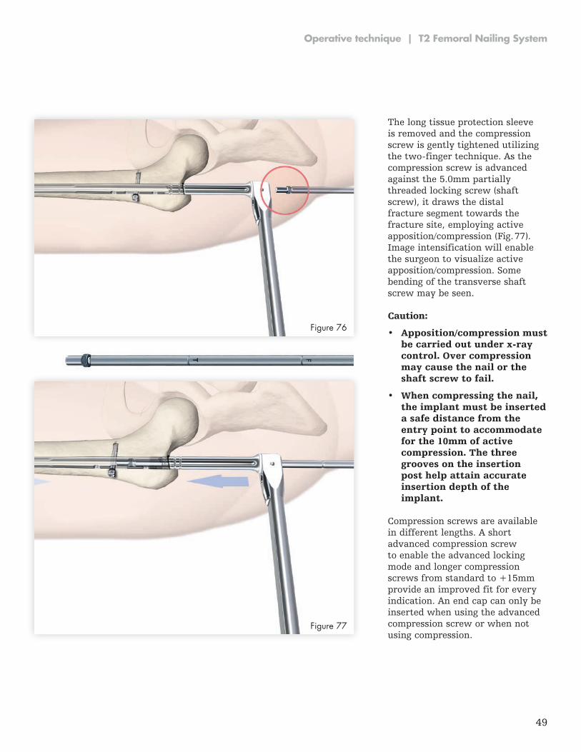
The long tissue protection sleeve is removed and the compression screw is gently tightened utilizing the two-finger technique. As the compression screw is advanced against the 5 .0mm partially thread ed locking screw (shaft screw), it draws the distal fracture segment towards the fracture site, employing active ap po si tion/compression (Fig . 77) . Image intensification will enable the surgeon to visualize active apposition/compression . Some bending of the transverse shaft screw may be seen .
Caution:
• Apposition/compression must be carried out under x-ray control. Over compression may cause the nail or the shaft screw to fail.
• When compressing the nail, the im plant must be inserted a safe distance from the entry point to accommodate for the 10mm of active compression. The three grooves on the insertion post help attain accurate insertion depth of the implant.
Compression screws are available in different lengths . A short advanced compression screw to enable the advanced locking mode and longer compression screws from standard to +15mm provide an improved fit for every indication . An end cap can only be inserted when using the advanced compression screw or when not using compression .
Figure 77
Figure 76
50
T2 Femoral Nailing System | Operative technique
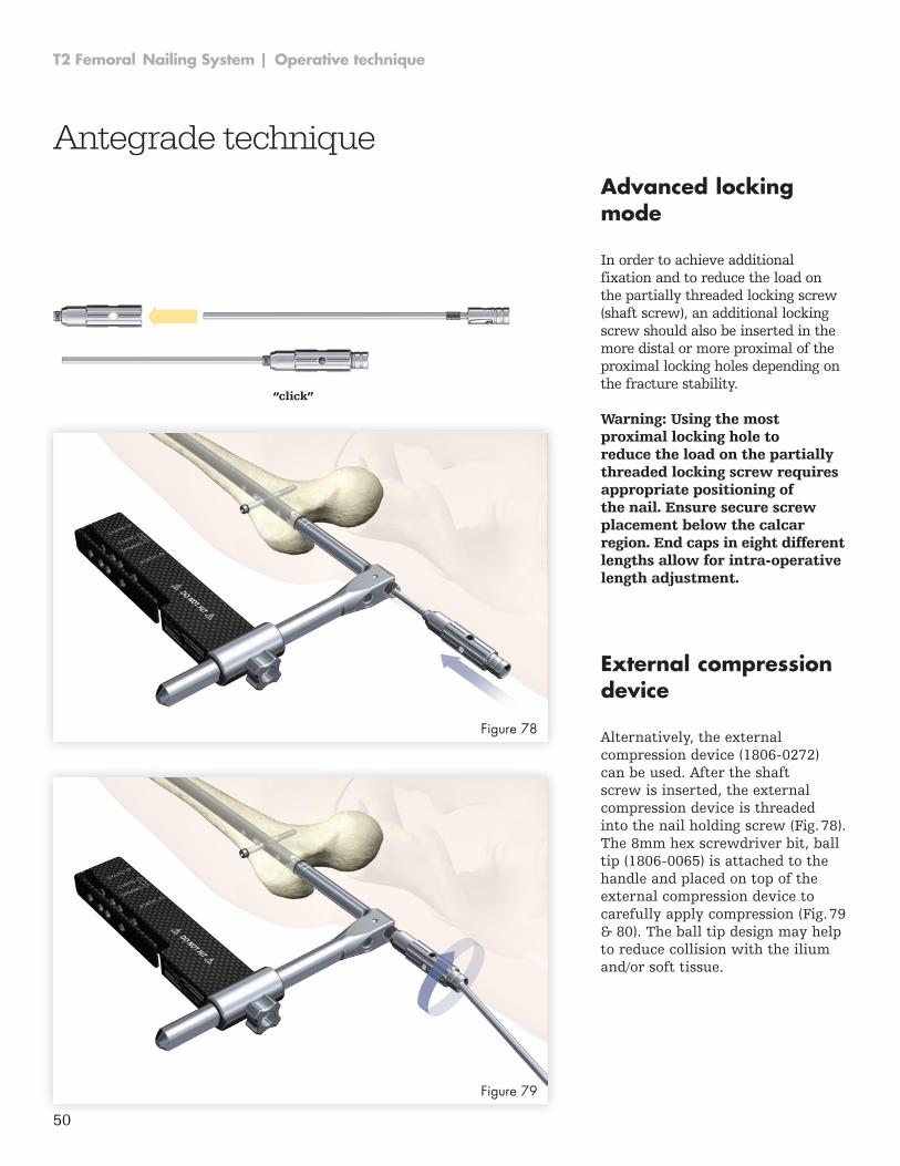
Advanced locking mode
In order to achieve additional fixation and to reduce the load on the partially threaded locking screw (shaft screw), an additional locking screw should also be inserted in the more distal or more proximal of the proximal locking holes depending on the fracture stability .
External compression device
Alternatively, the external compression device (1806-0272) can be used . After the shaft screw is inserted, the external compression device is threaded into the nail holding screw (Fig . 78) . The 8mm hex screwdriver bit, ball tip (1806-0065) is attached to the handle and placed on top of the external compression device to carefully apply compression (Fig . 79 & 80) . The ball tip design may help to reduce collision with the ilium and/or soft tissue .
Antegrade technique
Warning: Using the most proximal locking hole to reduce the load on the partially threaded locking screw requires appropriate positioning of the nail. Ensure secure screw placement below the calcar region. End caps in eight different lengths allow for intra-operative length adjustment.
“click”
Figure 78
Figure 79
51
Operative technique | T2 Femoral Nailing System
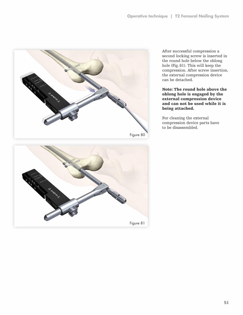
After successful compression a second locking screw is inserted in the round hole below the oblong hole (Fig . 81) . This will keep the compression . After screw insertion, the external compression device can be detached .
Note: The round hole above the oblong hole is engaged by the external compression device and can not be used while it is being attached.
For cleaning the external compression device parts have to be disassembled .
Figure 80
Figure 81
52
T2 Femoral Nailing System | Operative technique
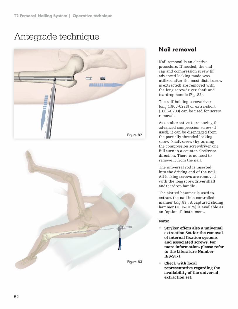
Nail removal
Nail removal is an elective procedure . If needed, the end cap and compres sion screw (if advanced locking mode was utilized after the most distal screw is extracted) are removed with the long screwdriver shaft and teardrop handle (Fig . 82) .
The self-holding screwdriver long (1806-0233) or extra-short (1806-0203) can be used for screw removal .
As an alternative to removing the advanced compression screw (if used), it can be disengaged from the partially threaded locking screw (shaft screw) by turning the compression screwdriver one full turn in a counter-clockwise direction . There is no need to remove it from the nail .
The universal rod is inserted into the driving end of the nail . All locking screws are removed with the long screwdriver shaft and teardrop handle .
The slotted hammer is used to extract the nail in a controlled manner (Fig . 83) . A captured sliding hammer (1806-0175) is available as an “optional” instrument .
Antegrade technique
Note:
• Stryker offers also a universal extraction Set for the removal of internal fixation systems and associated screws. For more information, please refer to the Literature Number IES-ST-1.
• Check with local representative regarding the availability of the universal extraction set.
Figure 82
Figure 83

53
Operative technique | T2 Femoral Nailing System
54
T2 Femoral Nailing System | Operative technique
Notes
55
Operative technique | T2 Femoral Nailing System
Notes

This document is intended solely for the use of healthcare professionals . A surgeon must always rely on his or her own professional clinical judgment when deciding whether to use a particular product when treating a particular patient . Stryker does not dispense medical advice and recommends that surgeons be trained in the use of any particular product before using it in surgery .
The information presented is intended to demonstrate a Stryker product . A surgeon must always refer to the package insert, product label and/or instructions for use, including the instructions for cleaning and sterilization (if applicable), before using any Stryker product . Products may not be available in all markets because product availability is subject to the regulatory and/or medical practices in individual markets . Please contact your Stryker representative if you have questions about the availability of Stryker products in your area .
Stryker Corporation or its affiliates own, use, or have applied for the following trademarks or service marks: Stryker, T2. All other trademarks are trademarks of their respective owners or holders .
Literature Number: T2-ST-15, 03-2016 Copyright © 2016 Stryker
Manufactured by:
Stryker Trauma GmbH Prof.-Küntscher-Str. 1-5 24232 Schönkirchen Germany
stryker .com