syst5030/4030 ☻error control☻ ☻ network architecture ☻ ☻ protocols ☻ ☻ transmission...
Post on 21-Dec-2015
219 views
TRANSCRIPT
SYST5030/4030
☻Error control☻ ☻ Network architecture ☻
☻ Protocols ☻ ☻ Transmission Efficiency and Throughput ☻
SYST5030/4030
Causes of errors
• Errors are caused by: – various kinds of surrounding noise which
disturbs the signal going through a medium like copper, coaxial cable, etc.
– properties of the medium • attenuation distortion (high frequencies lose
power more rapidly than low frequencies)• delay distortion (different frequencies travel
through the medium at different speeds)
SYST5030/4030
Error Prevention
• Shielding
• Relocating cables
• Conditioning (carriers guarantee the maximum number of errors that can occur)– C-type conditioning compensates for attenuation and
delay distortions.
– D-type conditioning improves signal to noise ratio.
SYST5030/4030
ERROR DETECTION AND CONTROLPARITY CHECKING
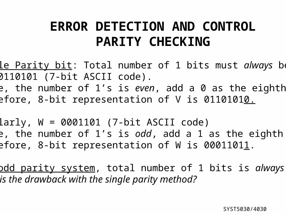
Single Parity bit: Total number of 1 bits must always be even.V = 0110101 (7-bit ASCII code). Since, the number of 1’s is even, add a 0 as the eighth bit.Therefore, 8-bit representation of V is 01101010.
Similarly, W = 0001101 (7-bit ASCII code)Since, the number of 1’s is odd, add a 1 as the eighth bit.Therefore, 8-bit representation of W is 00011011.
(In odd parity system, total number of 1 bits is always odd.)What is the drawback with the single parity method?
SYST5030/4030
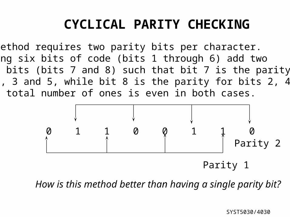
CYCLICAL PARITY CHECKING
This method requires two parity bits per character.Assuming six bits of code (bits 1 through 6) add twoparity bits (bits 7 and 8) such that bit 7 is the parity forbits 1, 3 and 5, while bit 8 is the parity for bits 2, 4, and 6.Again, total number of ones is even in both cases.
0 1 1 0 0 1 1 0
Parity 1
Parity 2
How is this method better than having a single parity bit?
SYST5030/4030
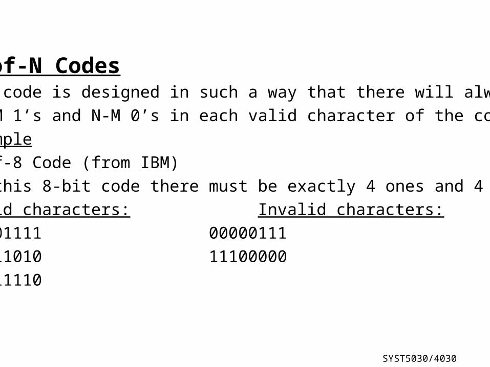
M-of-N CodesThe code is designed in such a way that there will always
be M 1’s and N-M 0’s in each valid character of the code.
Example
4-of-8 Code (from IBM)
In this 8-bit code there must be exactly 4 ones and 4 zeros.
Valid characters: Invalid characters:
00001111 00000111
01011010 11100000
00011110
SYST5030/4030
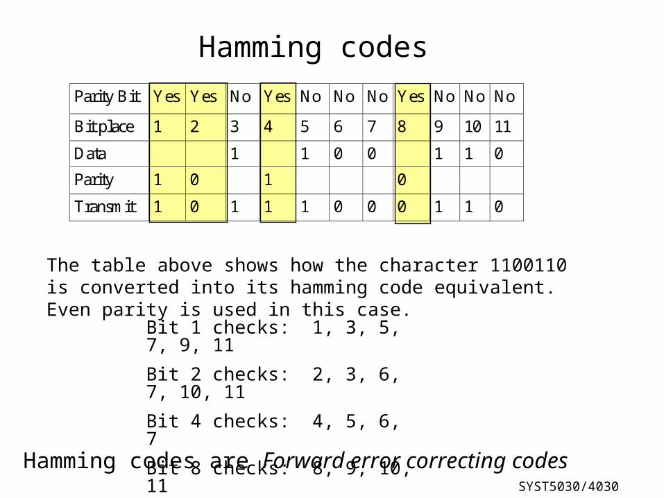
Parity Bit Yes Yes No Yes No No No Yes No No No
Bit place 1 2 3 4 5 6 7 8 9 10 11
Data 1 1 0 0 1 1 0
Parity 1 0 1 0
Transmit 1 0 1 1 1 0 0 0 1 1 0
The table above shows how the character 1100110 is converted into its hamming code equivalent. Even parity is used in this case.
Bit 1 checks: 1, 3, 5, 7, 9, 11
Bit 2 checks: 2, 3, 6, 7, 10, 11
Bit 4 checks: 4, 5, 6, 7
Bit 8 checks: 8, 9, 10, 11
Hamming codes
Hamming codes are Forward error correcting codes
SYST5030/4030
Cyclical Redundancy Check (CRC)
• This is applied to an entire block of data in synchronous communication.
• A 16-bit (or more commonly 32-bit) number is calculated from the entire block, and
attached to the end of the block by the sender.
• The receiver performs a similar calculation and compares the 16-bit value to see if it is the same. If they are not the same, it indicates an error in the transmission.
• This is a highly reliable scheme with almost 100% error detection capability.
SYST5030/4030
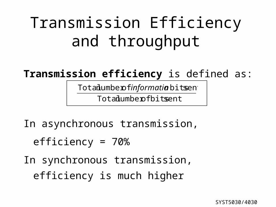
Transmission Efficiency and throughput
Transmission efficiency is defined as:
In asynchronous transmission, efficiency = 70%
In synchronous transmission, efficiency is much
higher
sent bits ofnumber Total
sent bits ofnumber Total ninformatio
SYST5030/4030
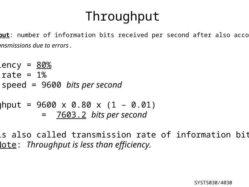
Throughput
Efficiency = 80%Error rate = 1%Modem speed = 9600 bits per second
Throughput = 9600 x 0.80 x (1 – 0.01) = 7603.2 bits per second
This is also called transmission rate of information bits. Note: Throughput is less than efficiency.
Throughput: number of information bits received per second after also accounting
for retransmissions due to errors.
SYST5030/4030
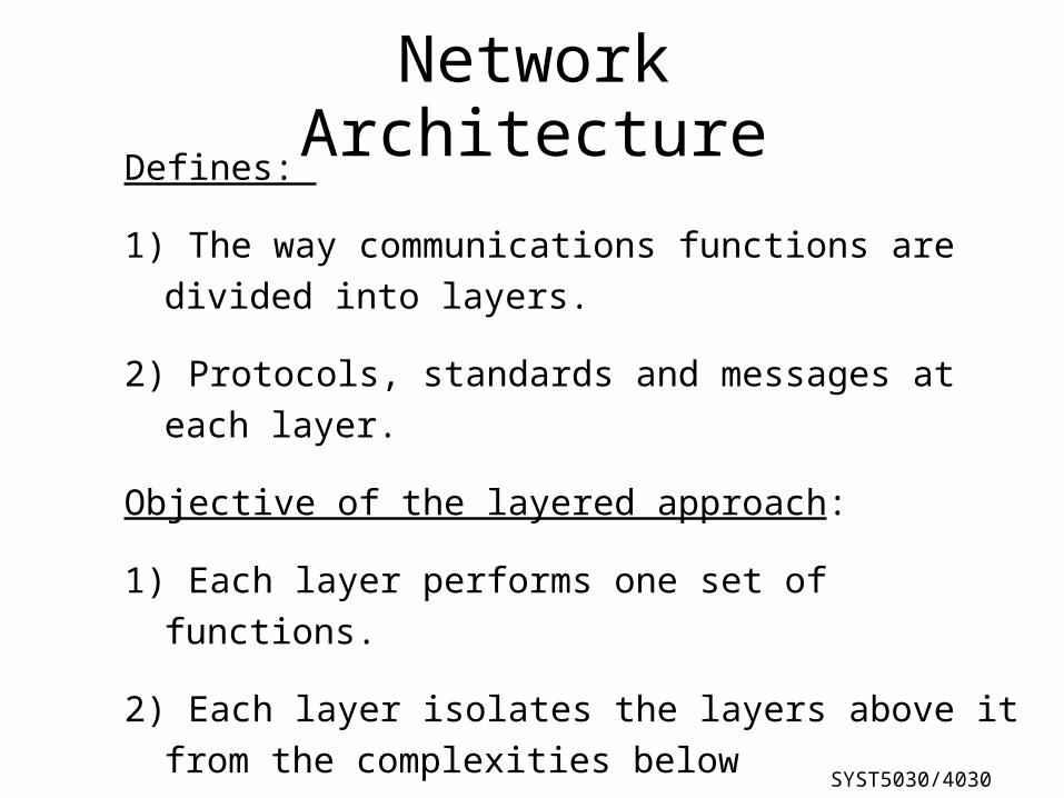
Network Architecture
Defines:
1) The way communications functions are divided into layers.
2) Protocols, standards and messages at each layer.
Objective of the layered approach:
1) Each layer performs one set of functions.
2) Each layer isolates the layers above it from the complexities below
Protocols in each layer are the set of rules agreed to and followed by both parties for successful communication.
SYST5030/4030
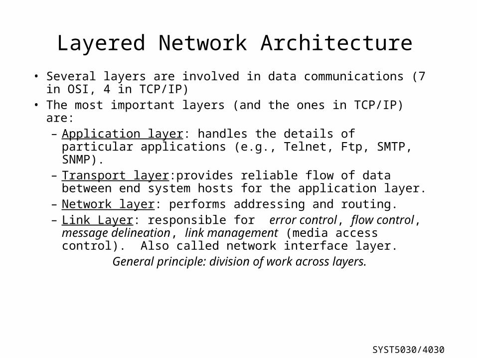
Layered Network Architecture
• Several layers are involved in data communications (7 in OSI, 4 in TCP/IP)
• The most important layers (and the ones in TCP/IP) are:– Application layer: handles the details of particular
applications (e.g., Telnet, Ftp, SMTP, SNMP). – Transport layer:provides reliable flow of data between end
system hosts for the application layer.– Network layer: performs addressing and routing.– Link Layer: responsible for error control, flow control,
message delineation, link management (media access control). Also called network interface layer.
General principle: division of work across layers.

SYST5030/4030
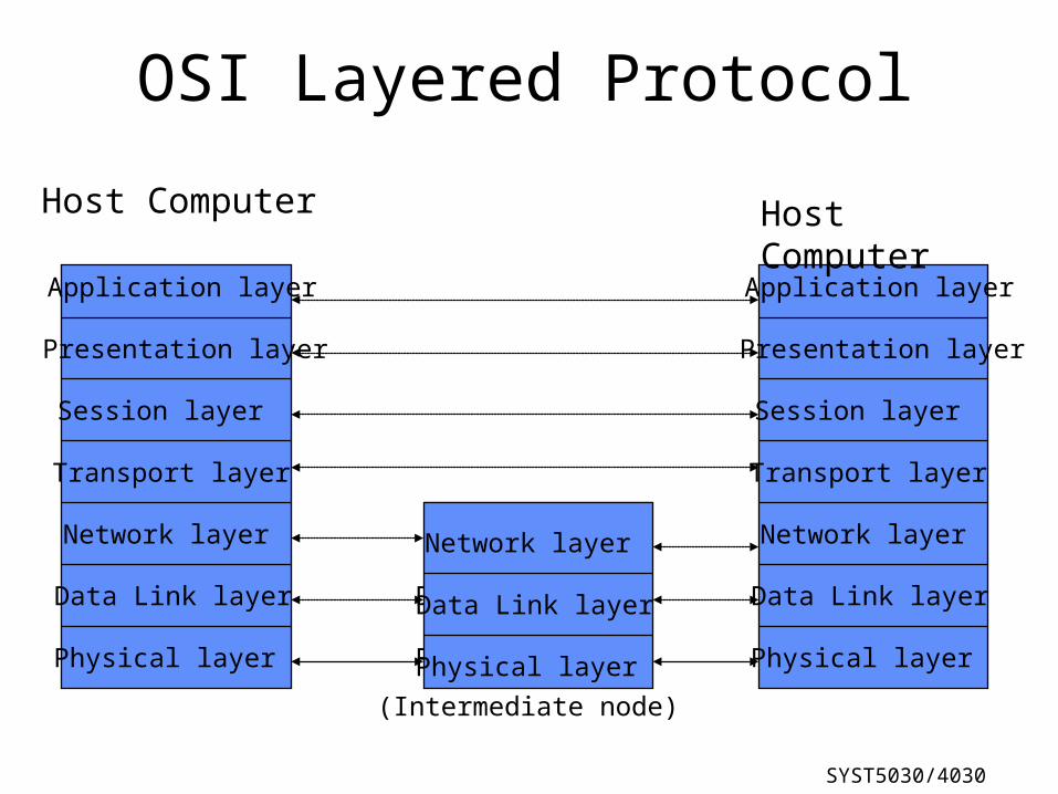
OSI Layered Protocol
Application layer
Presentation layer
Session layer
Transport layer
Network layer
Data Link layer
Physical layer
Application layer
Presentation layer
Session layer
Transport layer
Network layer
Data Link layer
Physical layer
Network layer
Data Link layer
Physical layer
Network layer
Data Link layer
Physical layer
Host Computer Host Computer
(Intermediate node)
SYST5030/4030
Application layer
Presentation layer
Session layer
Transport layer
Network layer
Data Link layer
Physical layer
ApplicationProgramming
Interface
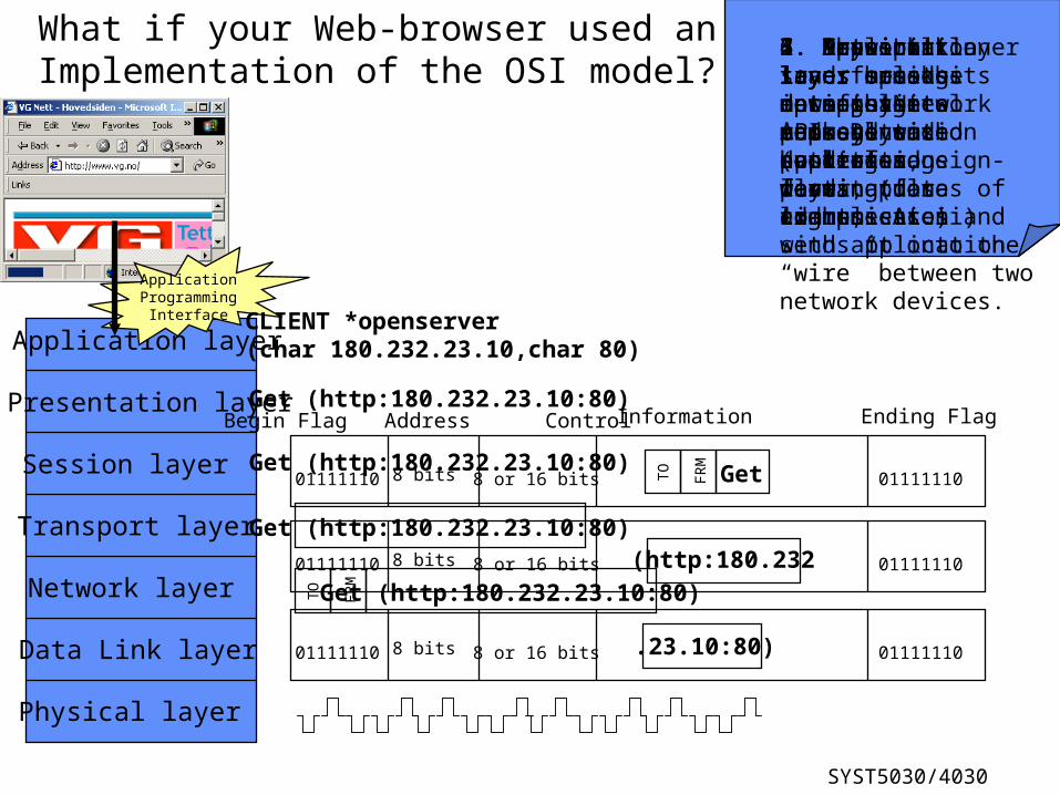
What if your Web-browser used an Implementation of the OSI model?
1. Application sends message down to Network API and application layer communicates with application
CLIENT *openserver (char 180.232.23.10,char 80)
Get (http:180.232.23.10:80)
2. Presentation layer encodes message into commonly used data storage format (for example Ascii)
3. Session layer notifies end-system host of a pending data transmission.
Get (http:180.232.23.10:80)
4. Transport layer splits data into packets and controls flow
Get (http:180.232.23.10:80)
5. Network layer encapsulates message with sender and destination address
Get (http:180.232.23.10:80)TO
FRM
6. Data Link layer breaks up message into DL size packets
(http:180.23201111110 8 bits 8 or 16 bits 01111110
01111110 8 bits 8 or 16 bits 01111110.23.10:80)
GetTO
FRM
01111110
Begin Flag Address Control
8 bits 8 or 16 bits
Information
01111110
Ending Flag
7. Physical layer transforms bits into physical representation (voltages, sign-waves, pulses of light, etc.) and sends it onto the “wire” between two network devices.
SYST5030/4030
Network layer
Data Link layer
Physical layer
Network layer
Data Link layer
Physical layer
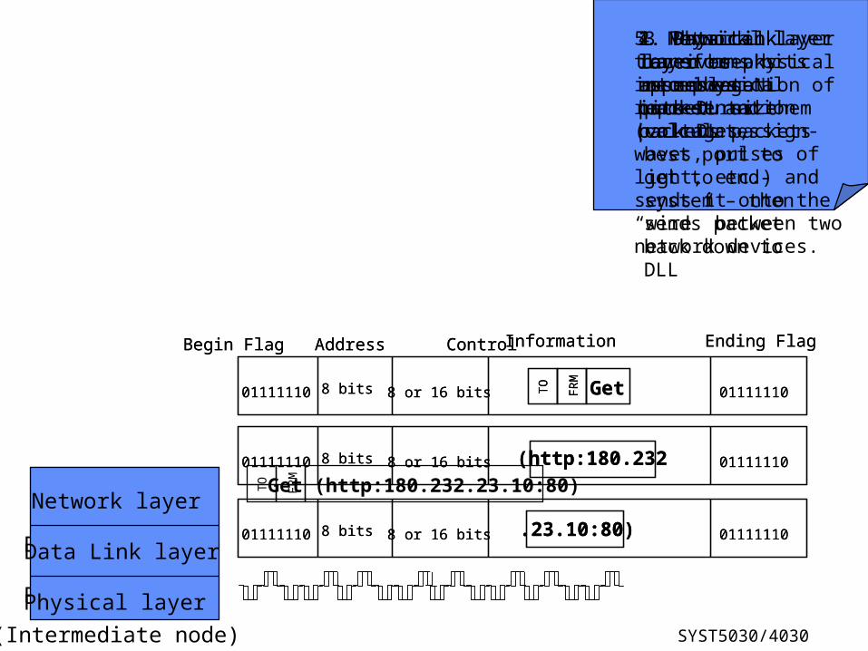
(Intermediate node)
1. Physical layer receives physical representation of bits turns them back DL packets
2. Data Link layer re-assembles NL packet
(http:180.23201111110 8 bits 8 or 16 bits 01111110
01111110 8 bits 8 or 16 bits 01111110.23.10:80)
GetTO
FRM
01111110
Begin Flag Address Control
8 bits 8 or 16 bits
Information
01111110
Ending Flag
3 Network layer receives packet and calculates best port to get to end-system – then sends packet back down to DLL
Get (http:180.232.23.10:80)TO
FRM
4. Data Link layer breaks up message into DL size packets
(http:180.23201111110 8 bits 8 or 16 bits 01111110
01111110 8 bits 8 or 16 bits 01111110.23.10:80)
GetTO
FRM
01111110
Begin Flag Address Control
8 bits 8 or 16 bits
Information
01111110
Ending Flag
5. Physical layer transforms bits into physical representation (voltages, sign-waves, pulses of light, etc.) and sends it onto the “wire” between two network devices.
SYST5030/4030
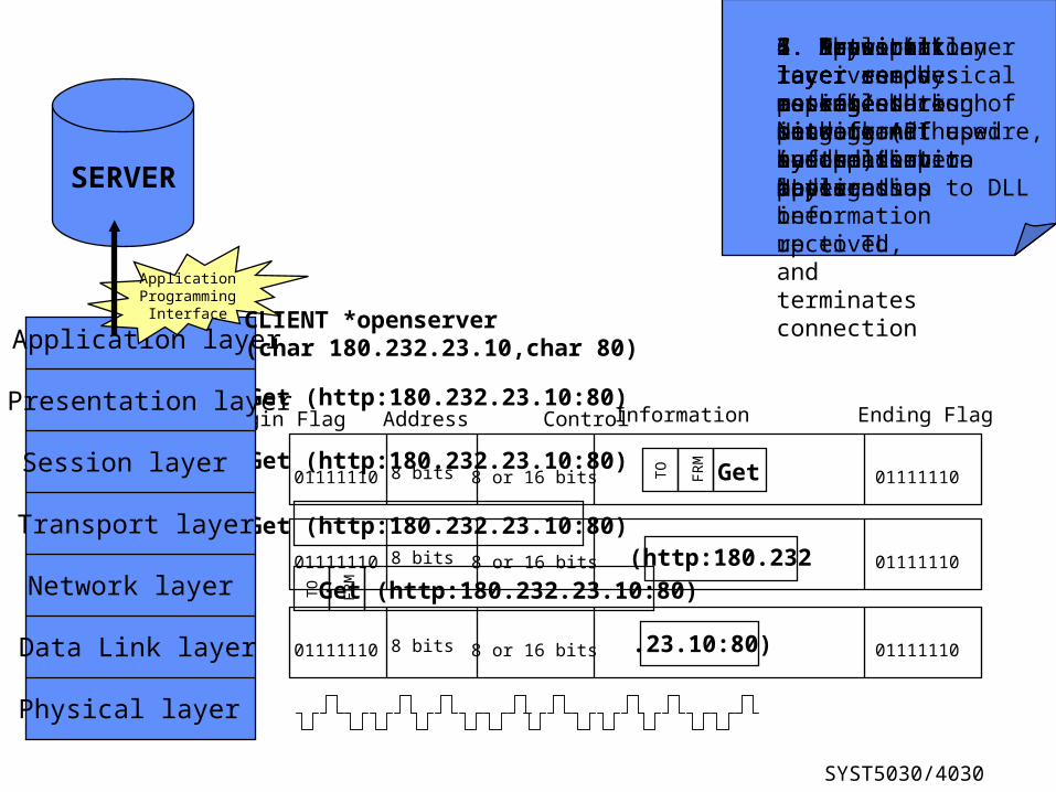
Get (http:180.232.23.10:80)
2. Presentation layer encodes message back into format used by application layer
3. Session layer notifies sending system that message has been received, and terminates connection
Get (http:180.232.23.10:80)
4. Transport layer re-assembles message (if needed)
Get (http:180.232.23.10:80)
5. Network layer removes packet/addressing information and sends information up to TL
Get (http:180.232.23.10:80)TO
FRM
6. Data Link layer re-assembles packet and sends it up to NL
(http:180.23201111110 8 bits 8 or 16 bits 01111110
01111110 8 bits 8 or 16 bits 01111110.23.10:80)
GetTO
FRM
01111110
Begin Flag Address Control
8 bits 8 or 16 bits
Information
01111110
Ending Flag
7. Physical layer receives physical representation of bits from the wire, and sends bit-patterns up to DLL
SERVER
Application layer
Presentation layer
Session layer
Transport layer
Network layer
Data Link layer
Physical layer
ApplicationProgramming
Interface
1. Application layer sends message through Network API up to the server application
CLIENT *openserver (char 180.232.23.10,char 80)
SYST5030/4030
OSI Layered Protocol
Application layer
Presentation layer
Session layer
Transport layer
Network layer
Data Link layer
Physical layer
Application layer
Presentation layer
Session layer
Transport layer
Network layer
Data Link layer
Physical layer
Network layer
Data Link layer
Physical layer
Network layer
Data Link layer
Physical layer
Host Computer Host Computer
(Intermediate node)
SYST5030/4030
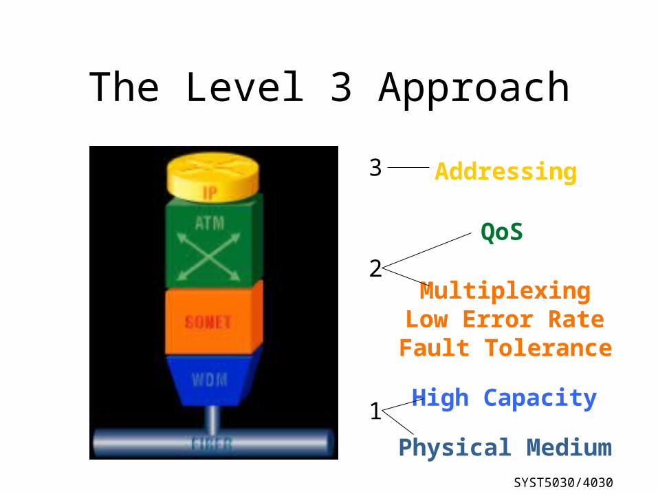
The Level 3 ApproachNetwork Layer Primary Attribute
Addressing
QoS
MultiplexingLow Error RateFault Tolerance
High Capacity
Physical Medium
1
2
3
SYST5030/4030
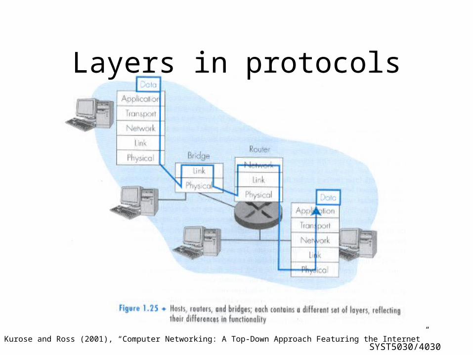
Layers in protocols
Source: Kurose and Ross (2001), “Computer Networking: A Top-Down Approach Featuring the Internet”

SYST5030/4030
Implementing an Architecture
• Each layer appends its own header to the application data.• At the receiving end, each layer strips off the corresponding
header.
SYST5030/4030
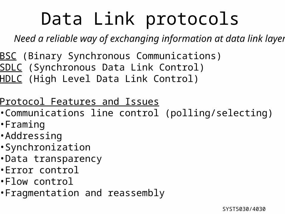
Data Link protocols
BSC (Binary Synchronous Communications)SDLC (Synchronous Data Link Control)HDLC (High Level Data Link Control)
Protocol Features and Issues•Communications line control (polling/selecting)•Framing•Addressing•Synchronization•Data transparency•Error control•Flow control•Fragmentation and reassembly
Need a reliable way of exchanging information at data link layer
SYST5030/4030
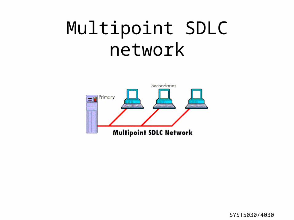
Multipoint SDLC network
SYST5030/4030
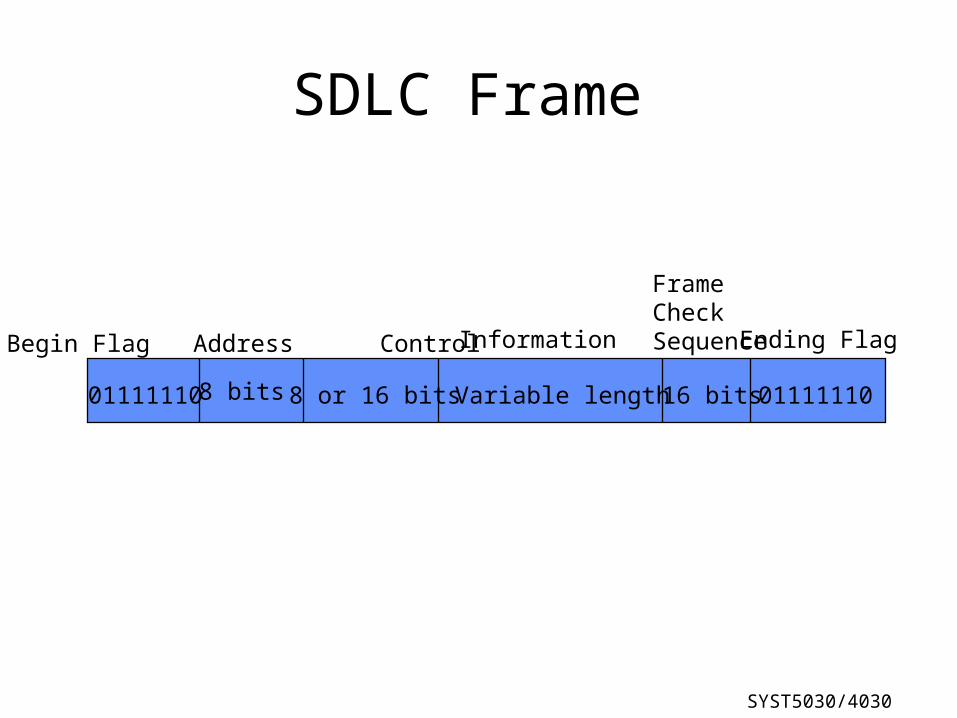
SDLC Frame
01111110
Begin Flag Address Control
8 bits 8 or 16 bits
Information
Variable length 16 bits
FrameCheckSequence
01111110
Ending Flag
SYST5030/4030
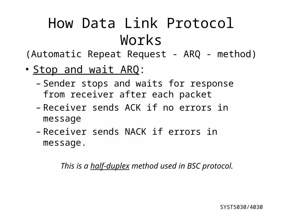
How Data Link Protocol Works(Automatic Repeat Request - ARQ - method)
• Stop and wait ARQ:– Sender stops and waits for response from
receiver after each packet– Receiver sends ACK if no errors in message– Receiver sends NACK if errors in message.
This is a half-duplex method used in BSC protocol.
SYST5030/4030
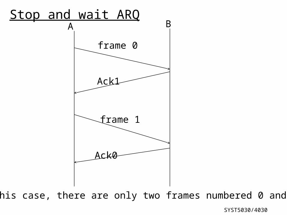
A B
frame 0
Ack1
frame 1
Ack0
Stop and wait ARQ
In this case, there are only two frames numbered 0 and 1
SYST5030/4030
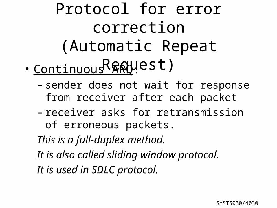
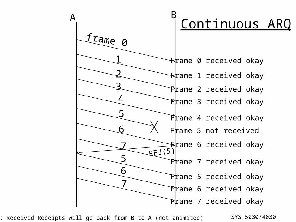
Protocol for error correction(Automatic Repeat Request)
• Continuous ARQ: – sender does not wait for response from receiver
after each packet– receiver asks for retransmission of erroneous
packets.
This is a full-duplex method.
It is also called sliding window protocol.
It is used in SDLC protocol.
SYST5030/4030
A B
frame 0
1
234
REJ(5)
6
7567
Continuous ARQ
Frame 0 received okay
Frame 1 received okay
Frame 2 received okay
Frame 3 received okay
Frame 4 received okay
Frame 5 not received
Frame 6 received okay
Frame 7 received okay
Frame 5 received okay
Frame 6 received okay
Frame 7 received okay
5
Note: Received Receipts will go back from B to A (not animated)