sylvania heaters
TRANSCRIPT
www.sylvaniaheaters.com
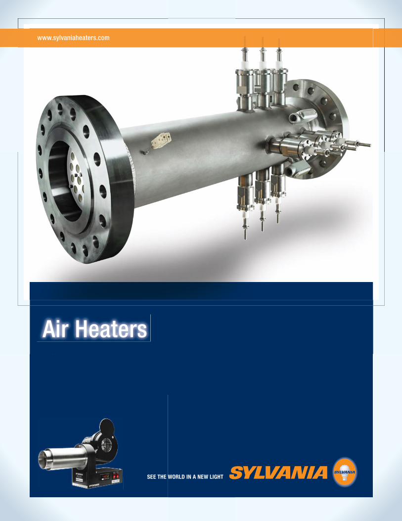
Air Heaters
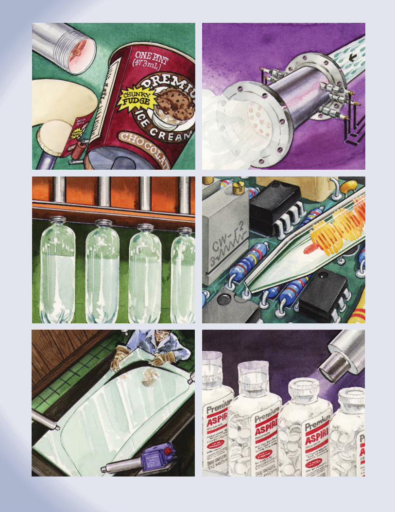
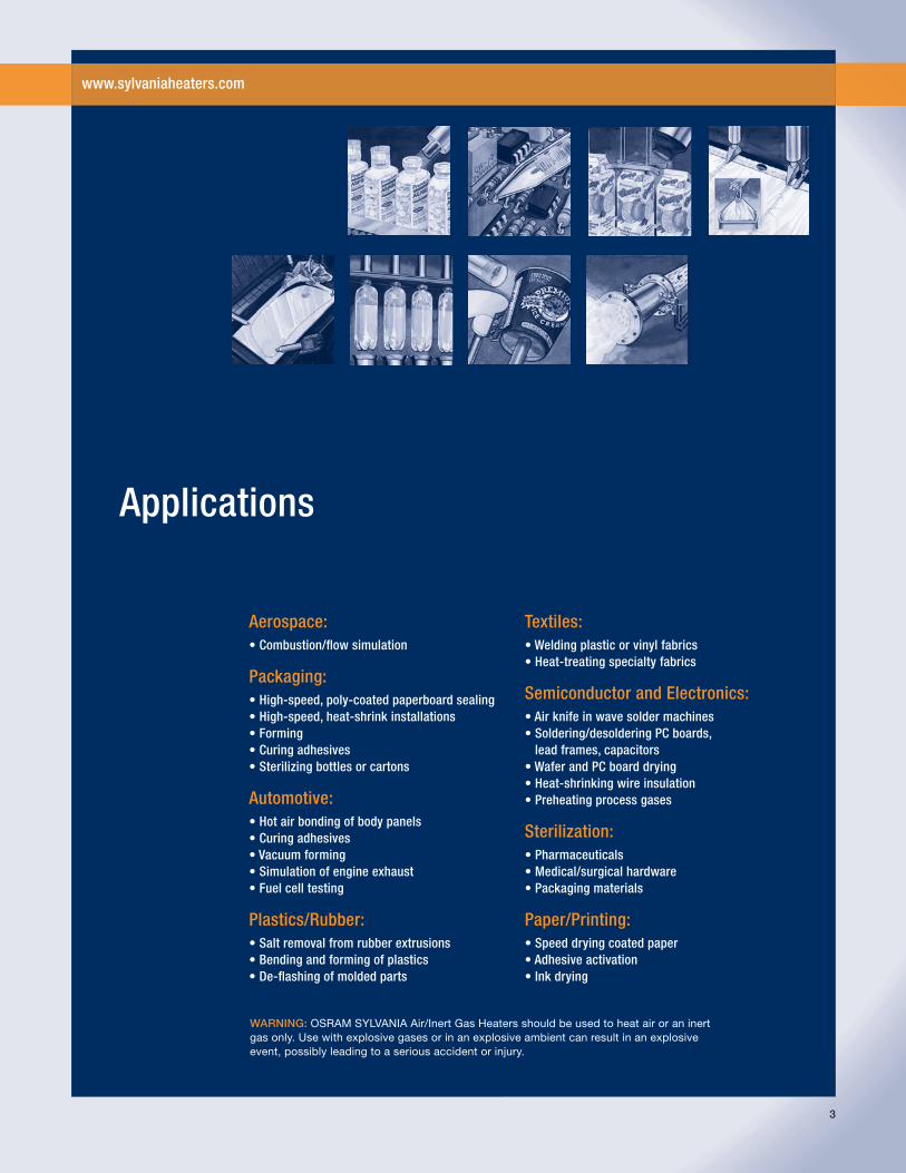
Applications
Aerospace:• Combustion/fl ow simulation
Packaging:• High-speed, poly-coated paperboard sealing• High-speed, heat-shrink installations• Forming• Curing adhesives• Sterilizing bottles or cartons
Automotive:• Hot air bonding of body panels• Curing adhesives• Vacuum forming• Simulation of engine exhaust• Fuel cell testing
Plastics/Rubber:• Salt removal from rubber extrusions• Bending and forming of plastics• De-fl ashing of molded parts
Textiles:• Welding plastic or vinyl fabrics• Heat-treating specialty fabrics
Semiconductor and Electronics:• Air knife in wave solder machines• Soldering/desoldering PC boards,
lead frames, capacitors• Wafer and PC board drying• Heat-shrinking wire insulation• Preheating process gases
Sterilization:• Pharmaceuticals• Medical/surgical hardware• Packaging materials
Paper/Printing:• Speed drying coated paper• Adhesive activation• Ink drying
WARNING: OSRAM SYLVANIA Air/Inert Gas Heaters should be used to heat air or an inert gas only. Use with explosive gases or in an explosive ambient can result in an explosive event, possibly leading to a serious accident or injury.
www.sylvaniaheaters.com
3
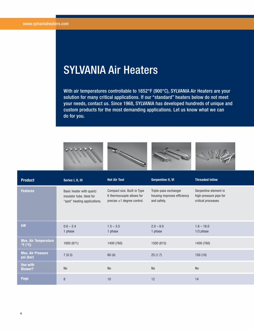
Series I, II, III
Basic heater with quartz insulator tube. Ideal for “spot” heating applications.
Hot Air Tool
Compact size. Built-in Type K thermocouple allows for precise ±1 degree control.
Serpentine II, VI
Triple-pass exchanger housing improves effi ciency and safety.
Threaded Inline
Serpentine element in high-pressure pipe for critical processes.
Product
Features
Max. Air Temperature °F (°C)
Use with Blower?
kW
Max. Air Pressurepsi (bar)
0.6 – 2.4 1 phase
1.5 – 3.5 1 phase
2.0 – 8.0 1 phase
1.6 – 18.0 1/3 phase
1600 (871) 1400 (760) 1500 (815) 1400 (760)
7 (0.5) 60 (4) 25 (1.7) 150 (10)
No No No No
8 10 12 14Page
www.sylvaniaheaters.com
With air temperatures controllable to 1652°F (900°C), SYLVANIA Air Heaters are your solution for many critical applications. If our “standard” heaters below do not meet your needs, contact us. Since 1968, SYLVANIA has developed hundreds of unique and custom products for the most demanding applications. Let us know what we can do for you.
SYLVANIA Air Heaters
4
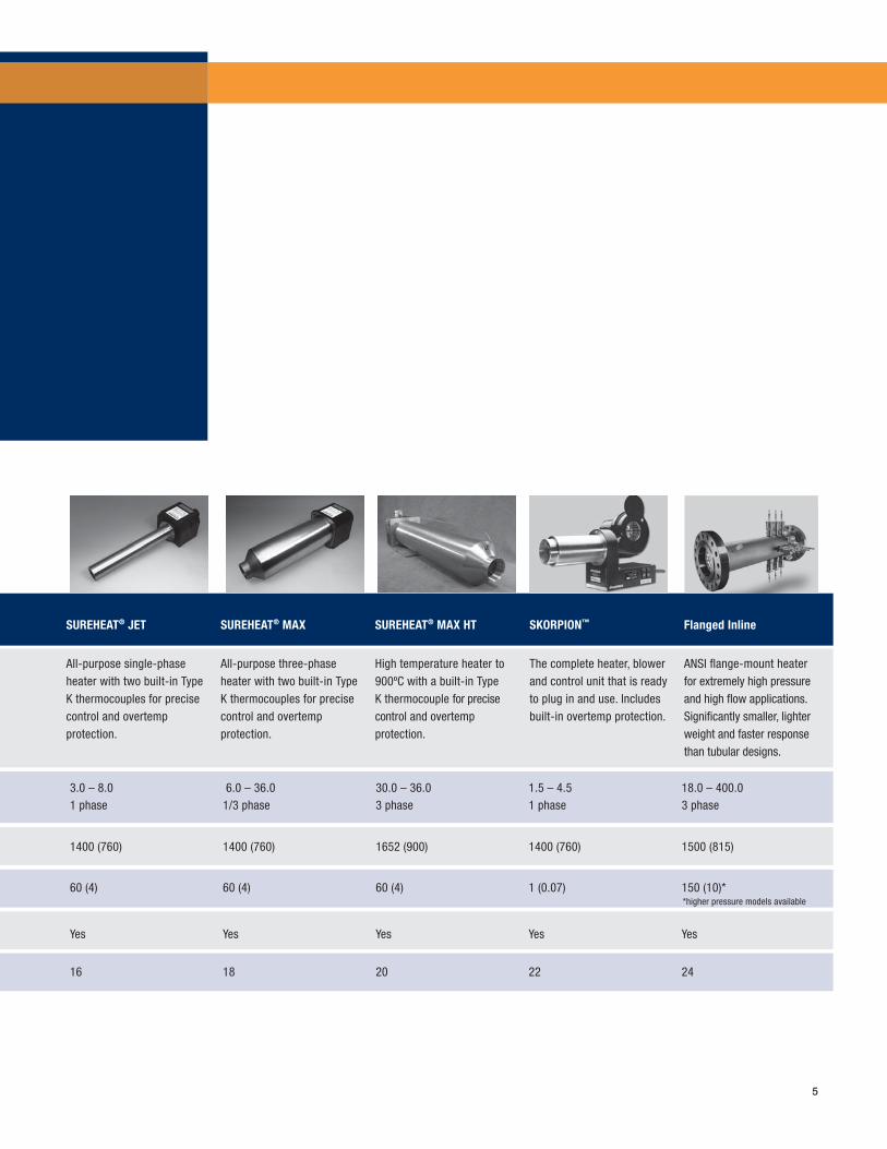
SUREHEAT® JET
All-purpose single-phase heater with two built-in Type K thermocouples for precise control and overtemp protection.
SUREHEAT® MAX
All-purpose three-phase heater with two built-in Type K thermocouples for precise control and overtemp protection.
SUREHEAT® MAX HT
High temperature heater to 900ºC with a built-in Type K thermocouple for precise control and overtemp protection.
SKORPION™
The complete heater, blower and control unit that is ready to plug in and use. Includes built-in overtemp protection.
Flanged Inline
ANSI fl ange-mount heater for extremely high pressure and high fl ow applications. Signifi cantly smaller, lighter weight and faster response than tubular designs.
3.0 – 8.0 1 phase
6.0 – 36.0 1/3 phase
30.0 – 36.0 3 phase
1.5 – 4.5 1 phase
18.0 – 400.0 3 phase
1400 (760) 1400 (760) 1652 (900) 1400 (760) 1500 (815)
60 (4) 60 (4) 60 (4) 1 (0.07) 150 (10)*
Yes Yes Yes Yes Yes
16 18 20 22 24
5
*higher pressure models available
www.sylvaniaheaters.com
6
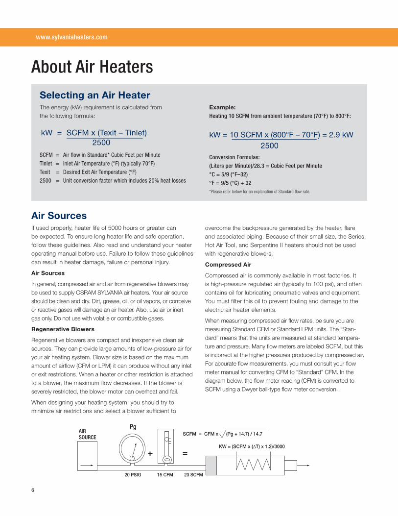
About Air Heaters
Selecting an Air HeaterThe energy (kW) requirement is calculated from the following formula:
SCFM = Air fl ow in Standard* Cubic Feet per Minute
Tinlet = Inlet Air Temperature (°F) (typically 70°F)
Texit = Desired Exit Air Temperature (°F)
2500 = Unit conversion factor which includes 20% heat losses
Example: Heating 10 SCFM from ambient temperature (70°F) to 800°F:
kW = 10 SCFM x (800°F – 70°F) = 2.9 kW 2500Conversion Formulas:
(Liters per Minute)/28.3 = Cubic Feet per Minute
°C = 5/9 (°F–32)
°F = 9/5 (°C) + 32*Please refer below for an explanation of Standard fl ow rate.
Air SourcesIf used properly, heater life of 5000 hours or greater can be expected. To ensure long heater life and safe operation, follow these guidelines. Also read and understand your heater operating manual before use. Failure to follow these guidelines can result in heater damage, failure or personal injury.
Air Sources
In general, compressed air and air from regenerative blowers may be used to supply OSRAM SYLVANIA air heaters. Your air source should be clean and dry. Dirt, grease, oil, or oil vapors, or corrosive or reactive gases will damage an air heater. Also, use air or inert gas only. Do not use with volatile or combustible gases.
Regenerative Blowers
Regenerative blowers are compact and inexpensive clean air sources. They can provide large amounts of low-pressure air for your air heating system. Blower size is based on the maximum amount of airfl ow (CFM or LPM) it can produce without any inlet or exit restrictions. When a heater or other restriction is attached to a blower, the maximum fl ow decreases. If the blower is severely restricted, the blower motor can overheat and fail.
When designing your heating system, you should try to minimize air restrictions and select a blower suffi cient to
overcome the backpressure generated by the heater, fl are and associated piping. Because of their small size, the Series, Hot Air Tool, and Serpentine II heaters should not be used with regenerative blowers.
Compressed Air
Compressed air is commonly available in most factories. It is high-pressure regulated air (typically to 100 psi), and often contains oil for lubricating pneumatic valves and equipment. You must fi lter this oil to prevent fouling and damage to theelectric air heater elements.
When measuring compressed air fl ow rates, be sure you are measuring Standard CFM or Standard LPM units. The “Stan-dard” means that the units are measured at standard tempera-ture and pressure. Many fl ow meters are labeled SCFM, but this is incorrect at the higher pressures produced by compressed air. For accurate fl ow measurements, you must consult your fl ow meter manual for converting CFM to “Standard” CFM. In the diagram below, the fl ow meter reading (CFM) is converted to SCFM using a Dwyer ball-type fl ow meter conversion.
kW = SCFM x (Texit – Tinlet) 2500
AIR SOURCE
20 PSIG 15 CFM 23 SCFM
KW = (SCFM x (ΔT) x 1.2)/3000
PgSCFM = CFM x (Pg + 14.7) / 14.7
7
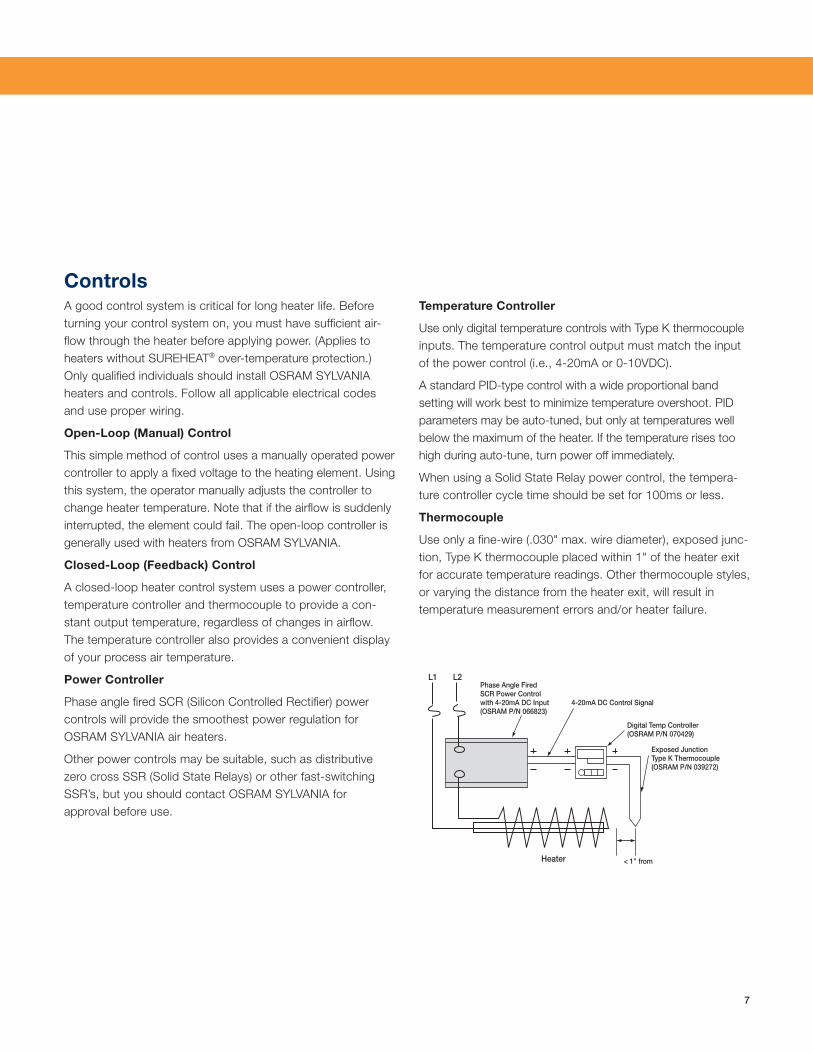
ControlsA good control system is critical for long heater life. Before turning your control system on, you must have suffi cient air-fl ow through the heater before applying power. (Applies to heaters without SUREHEAT® over-temperature protection.) Only qualifi ed individuals should install OSRAM SYLVANIA heaters and controls. Follow all applicable electrical codes and use proper wiring.
Open-Loop (Manual) Control
This simple method of control uses a manually operated power controller to apply a fi xed voltage to the heating element. Using this system, the operator manually adjusts the controller to change heater temperature. Note that if the airfl ow is suddenly interrupted, the element could fail. The open-loop controller is generally used with heaters from OSRAM SYLVANIA.
Closed-Loop (Feedback) Control
A closed-loop heater control system uses a power controller, temperature controller and thermocouple to provide a con-stant output temperature, regardless of changes in airfl ow. The temperature controller also provides a convenient display of your process air temperature.
Power Controller
Phase angle fi red SCR (Silicon Controlled Rectifi er) power controls will provide the smoothest power regulation for OSRAM SYLVANIA air heaters.
Other power controls may be suitable, such as distributive zero cross SSR (Solid State Relays) or other fast-switching SSR’s, but you should contact OSRAM SYLVANIA for approval before use.
Temperature Controller
Use only digital temperature controls with Type K thermocouple inputs. The temperature control output must match the input of the power control (i.e., 4-20mA or 0-10VDC).
A standard PID-type control with a wide proportional band setting will work best to minimize temperature overshoot. PID parameters may be auto-tuned, but only at temperatures well below the maximum of the heater. If the temperature rises too high during auto-tune, turn power off immediately.
When using a Solid State Relay power control, the tempera-ture controller cycle time should be set for 100ms or less.
Thermocouple
Use only a fi ne-wire (.030" max. wire diameter), exposed junc-tion, Type K thermocouple placed within 1" of the heater exit for accurate temperature readings. Other thermocouple styles, or varying the distance from the heater exit, will result in temperature measurement errors and/or heater failure.
L1 L2
Heater < 1” from
4-20mA DC Control Signal
Digital Temp Controller(OSRAM P/N 070429)
Exposed JunctionType K Thermocouple(OSRAM P/N 039272)
Phase Angle FiredSCR Power Controlwith 4-20mA DC Input(OSRAM P/N 066823)
8
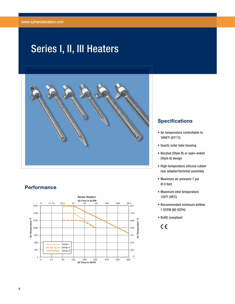
1600
1400
1200
1000
800
600
400
0
Air
Tem
per
atur
e ˚F
0 25 50 100 200 300 400 500 600Air Flow in SCFH
Series Heaters
0 11.75 23.5 47 94 142 189 236 283871
760
649
538
427
316
204
0
Air
Tem
per
atur
e ˚C
Air Flow in SLPM
Series ISeries IISeries III
Performance
• Air temperature controllable to
1600˚F (871˚C)
• Quartz outer tube housing
• Nozzled (Style B) or open-ended
(Style A) design
• High-temperature silicone rubber
rear adapter/terminal assembly
• Maximum air pressure 7 psi
(0.5 bar)
• Maximum inlet temperature
120˚F (49˚C)
• Recommended minimum airfl ow
1 SCFM (60 SCFH)
• RoHS compliant
Specifi cations
Series I, II, III Heaters
www.sylvaniaheaters.com
9
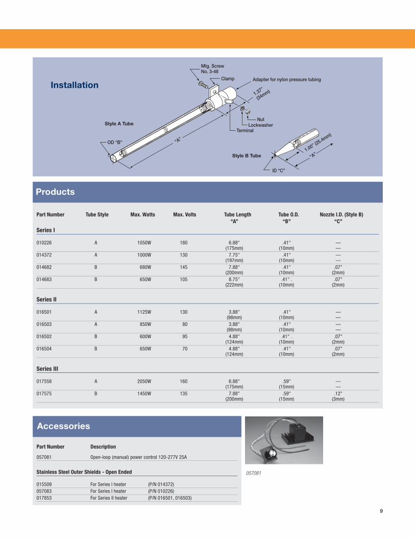
Part Number Tube Style Max. Watts Max. Volts Tube Length Tube O.D. Nozzle I.D. (Style B) “A” “B” “C”
Series I
010226 A 1050W 180 6.88" .41" — (175mm) (10mm) —014372 A 1000W 130 7.75" .41" — (197mm) (10mm) —014682 B 680W 145 7.88" .41" .07" (200mm) (10mm) (2mm)014683 B 650W 105 8.75" .41" . .07" (222mm) (10mm) (2mm)
Series II
016501 A 1125W 130 3.88" .41" — (98mm) (10mm) —016503 A 850W 80 3.88" .41" — (98mm) (10mm) —016502 B 600W 95 4.88" .41" . .07" (124mm) (10mm) (2mm)016504 B 650W 70 4.88" .41" .07" (124mm) (10mm) (2mm)
Series III
017558 A 2050W 160 6.88" .59" — (175mm) (15mm) —017575 B 1450W 135 7.88" .59" .12" (200mm) (15mm) (3mm)
Products
Installation
Part Number Description
057081 Open-loop (manual) power control 120-277V 25A
Stainless Steel Outer Shields - Open Ended
015509 For Series I heater (P/N 014372)057083 For Series I heater (P/N 010226)017853 For Series II heater (P/N 016501, 016503)
Accessories
057081
Clamp
OD “B”
ID “C”
“A”1.00” (2
5.4mm)
1.37”
(34mm)
“A”
Mtg. ScrewNo. 3-48
Adapter for nylon pressure tubing
TerminalLockwasher
NutStyle A Tube
Style B Tube
10
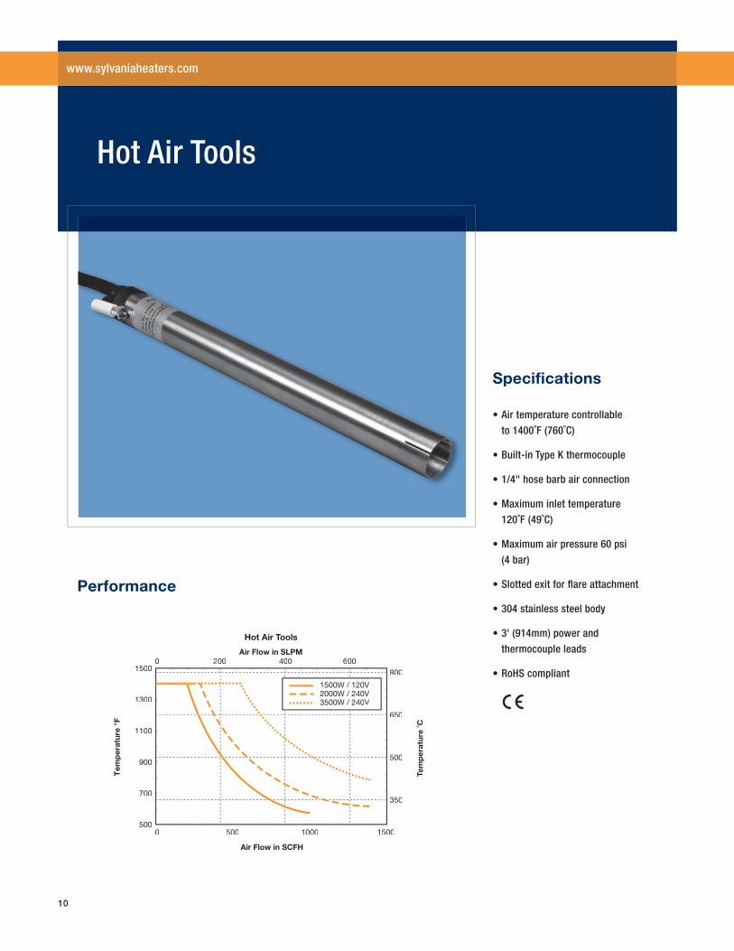
0 500 1000 1500
0 200 400 600800
650
500
350
1500
1300
1100
900
700
500
Tem
per
atur
e °F
Tem
per
atur
TTe
˚C
Air Flow in SCFH
Air Flow in SLPM
1500W / 120V2000W / 240V3500W / 240V
Hot Air ToolTT s
Performance
• Air temperature controllable
to 1400˚F (760˚C)
• Built-in Type K thermocouple
• 1/4" hose barb air connection
• Maximum inlet temperature
120˚F (49˚C)
• Maximum air pressure 60 psi
(4 bar)
• Slotted exit for fl are attachment
• 304 stainless steel body
• 3' (914mm) power and
thermocouple leads
• RoHS compliant
Specifi cations
Hot Air Tools
www.sylvaniaheaters.com
11
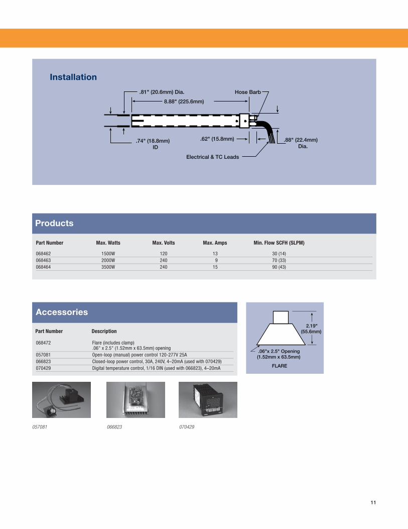
068472 Flare (includes clamp) .06" x 2.5" (1.52mm x 63.5mm) opening057081 Open-loop (manual) power control 120-277V 25A066823 Closed-loop power control, 30A, 240V, 4–20mA (used with 070429)070429 Digital temperature control, 1/16 DIN (used with 066823), 4–20mA
Part Number Max. Watts Max. Volts Max. Amps Min. Flow SCFH (SLPM)
068462 1500W 120 13 30 (14)068463 2000W 240 9 70 (33)068464 3500W 240 15 90 (43)
Part Number Description
Products
Installation
Accessories
057081 070429066823
.81" (20.6mm) Dia.
8.88" (225.6mm)
Hose Barb
.74" (18.8mm)ID
.62" (15.8mm)
Electrical & TC Leads
.88" (22.4mm)Dia.
2.19"(55.6mm)
.06"x 2.5" Opening(1.52mm x 63.5mm)
FLARE
12
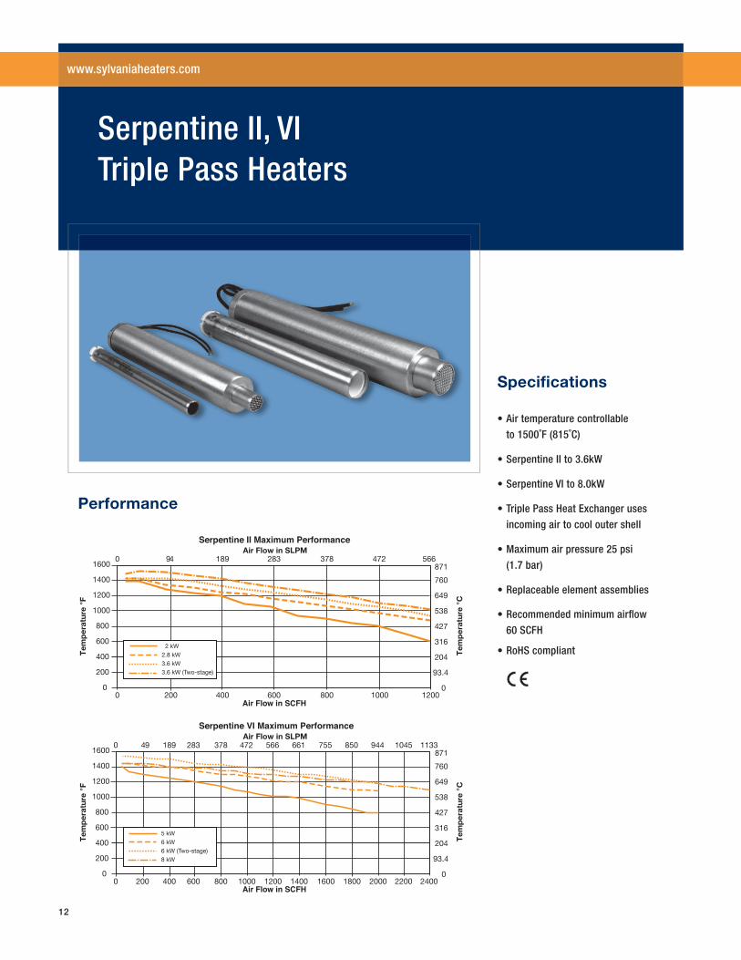
Performance
• Air temperature controllable
to 1500˚F (815˚C)
• Serpentine II to 3.6kW
• Serpentine VI to 8.0kW
• Triple Pass Heat Exchanger uses
incoming air to cool outer shell
• Maximum air pressure 25 psi
(1.7 bar)
• Replaceable element assemblies
• Recommended minimum airfl ow
60 SCFH
• RoHS compliant
Specifi cations
Serpentine II, VI Triple Pass Heaters
www.sylvaniaheaters.com
1600
1400
1200
1000
800
600
400
200
00 200 400 600 800 1000 1200
871
760
649
538
427
316
204
93.4
0
0 94 189 283 378 472 566
2 kW2.8 kW3.6 kW3.6 kW (Two-stage)
1600
1400
1200
1000
800
600
400
200
00 200 400 600 800 1000 1200 1400 1600 1800 2000 2200 2400
0 94 189 283 378 472 566 661 755 850 944 1045 1133
5 kW6 kW6 kW (Two-stage)8 kW
Tem
per
atur
e °F
Serpentine II Maximum Performance
Air Flow in SCFH
Air Flow in SLPM
Tem
per
atur
e °C
Tem
per
atur
e °F
Serpentine VI Maximum Performance
Air Flow in SCFH
Air Flow in SLPM
Tem
per
atur
e °C
871
760
649
538
427
316
204
93.4
0
13
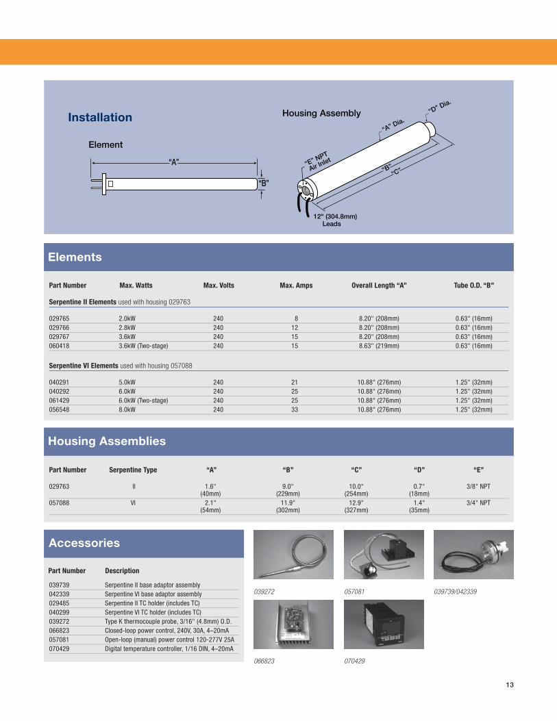
Part Number Max. Watts Max. Volts Max. Amps Overall Length “A” Tube O.D. “B”
Serpentine II Elements used with housing 029763
029765 2.0kW 240 8 8.20" (208mm) 0.63" (16mm)029766 2.8kW 240 12 8.20" (208mm) 0.63" (16mm)029767 3.6kW 240 15 8.20" (208mm) 0.63" (16mm)060418 3.6kW (Two-stage) 240 15 8.63" (219mm) 0.63" (16mm)
Serpentine VI Elements used with housing 057088
040291 5.0kW 240 21 10.88" (276mm) 1.25" (32mm)040292 6.0kW 240 25 10.88" (276mm) 1.25" (32mm)061429 6.0kW (Two-stage) 240 25 10.88" (276mm) 1.25" (32mm)056548 8.0kW 240 33 10.88" (276mm) 1.25" (32mm)
Part Number Serpentine Type “A” “B” “C” “D” “E”
029763 ll 1.6" 9.0" 10.0" 0.7" 3/8" NPT (40mm) (229mm) (254mm) (18mm)057088 Vl 2.1" 11.9" 12.9" 1.4" 3/4" NPT (54mm) (302mm) (327mm) (35mm)
Elements
Installation
Element
“A”
“B”
Housing Assemblies
039272 039739 Serpentine II base adaptor assembly042339 Serpentine VI base adaptor assembly029485 Serpentine II TC holder (includes TC)040299 Serpentine VI TC holder (includes TC)039272 Type K thermocouple probe, 3/16" (4.8mm) O.D.066823 Closed-loop power control, 240V, 30A, 4–20mA057081 Open-loop (manual) power control 120-277V 25A070429 Digital temperature controller, 1/16 DIN, 4–20mA
Part Number Description
Accessories
066823
057081
070429
12" (304.8mm)Leads
“B”“C”
“A” Dia.
“D” Dia.
“E” NPT
Air Inlet
Housing Assembly
039739/042339
14
Tem
per
atu
re ˚
F
Inline Heaters Maximum Performance
Tem
per
atu
re ˚
C
Air Flow in SCFH
1600
1400
1200
1000
800
600
400
200
00 200 400 600 800 1000 1200 1400 1600 1800 2000 2200 2400 3000 4000 5000 6000 7000 8000
871
760
649
538
427
316
204
93.4
0
0 94 189 283 378 472 566 661 755 850 944 1045 1133 1416 1888 2360 2832 3304 3776Air Flow in SLPM
1.6 kW 4.0 kW 6.0 kW18.0 kW
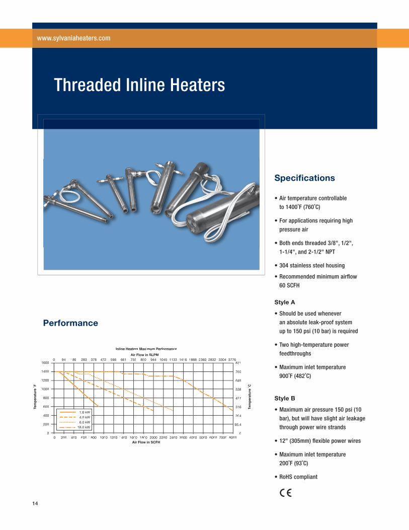
Performance
• Air temperature controllable
to 1400˚F (760˚C)
• For applications requiring high
pressure air
• Both ends threaded 3/8", 1/2",
1-1/4", and 2-1/2" NPT
• 304 stainless steel housing
• Recommended minimum airfl ow
60 SCFH
Style A
• Should be used whenever
an absolute leak-proof system
up to 150 psi (10 bar) is required
• Two high-temperature power
feedthroughs
• Maximum inlet temperature
900˚F (482˚C)
Style B
• Maximum air pressure 150 psi (10
bar), but will have slight air leakage
through power wire strands
• 12" (305mm) fl exible power wires
• Maximum inlet temperature
200˚F (93˚C)
• RoHS compliant
Specifi cations
Threaded Inline Heaters
www.sylvaniaheaters.com
15
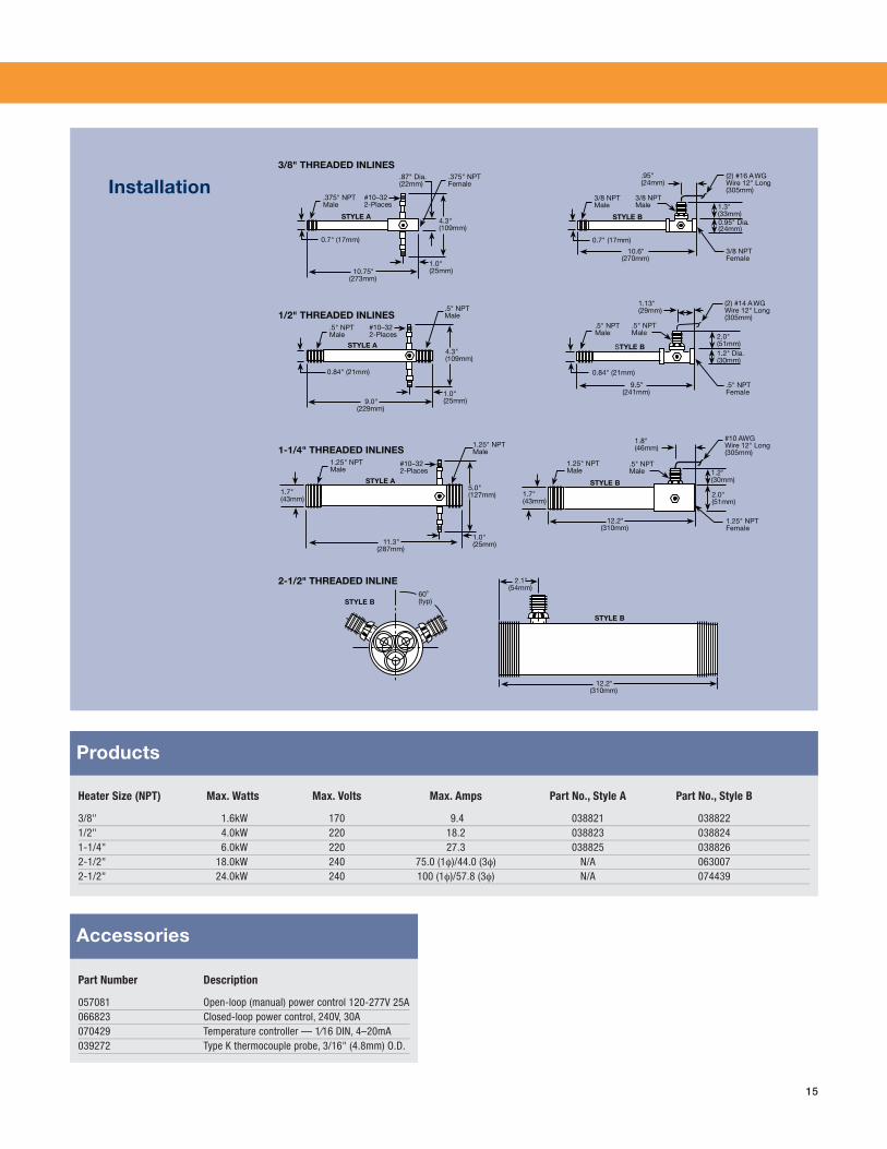
Part Number Description
057081 Open-loop (manual) power control 120-277V 25A066823 Closed-loop power control, 240V, 30A070429 Temperature controller — 1⁄16 DIN, 4–20mA039272 Type K thermocouple probe, 3/16" (4.8mm) O.D.
Heater Size (NPT) Max. Watts Max. Volts Max. Amps Part No., Style A Part No., Style B
3/8" 1.6kW 170 9.4 038821 0388221/2" 4.0kW 220 18.2 038823 0388241-1/4" 6.0kW 220 27.3 038825 0388262-1/2" 18.0kW 240 75.0 (1φ)/44.0 (3φ) N/A 0630072-1/2" 24.0kW 240 100 (1φ)/57.8 (3φ) N/A 074439
Products
Installation
Accessories
0.84" (21mm)
9.0"(229mm)
1.0"(25mm)
4.3"(109mm)
#10–322-Places
STYLE A
.5" NPTMale
.5" NPTMale
11.3"(287mm)
1.7"(43mm)
1.0"(25mm)
5.0"(127mm)
#10–322-Places
STYLE A
1.25" NPTMale
1.25" NPTMale
10.75"(273mm)
0.7" (17mm)
1.0"(25mm)
4.3"(109mm)
.87" Dia.(22mm)
#10–322-Places
STYLE A
.375" NPTMale
.375" NPTFemale
60˚(typ)STYLE B
.5" NPTFemale
0.84" (21mm)
9.5"(241mm)
2.0"(51mm)1.2" Dia.(30mm)
(2) #14 AWGWire 12" Long(305mm)
1.13"(29mm)
.5" NPTMale
STYLE B
.5" NPTMale
0.7" (17mm)
10.6"(270mm)
3/8 NPTFemale
1.3"(33mm)0.95" Dia.(24mm)
(2) #16 AWGWire 12" Long(305mm)
.95"(24mm)
3/8 NPTMale
STYLE B
3/8 NPTMale
#10 AWGWire 12" Long(305mm)
1.8"(46mm)
12.2"(310mm)
1.25" NPTFemale
1.2"(30mm)
2.0"(51mm)
.5" NPTMale
STYLE B
1.25" NPTMale
1.7"(43mm)
12.2"(310mm)
STYLE B
2.1"(54mm)
3/8" THREADED INLINES
1/2" THREADED INLINES
1-1/4" THREADED INLINES
2-1/2" THREADED INLINE
16
0
200
400
600
800
1000
1200
1400
1600
2 3 5 7 8 10 12 13 15 17 18 20 22 23 25 27 28 30
-30
70
170
270
370
470
570
670
770
870
47 94 142 189 236 283 330 377 425 472 519 566 613 660 708 755 802 849
Air Flow in SCFM
Tem
per
atu
re ˚
FTT T e
mp
erat
ure
˚C
TT
Air Flow in SLPM
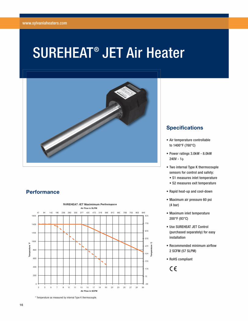
SUREHEAT JET Maximimum Performance
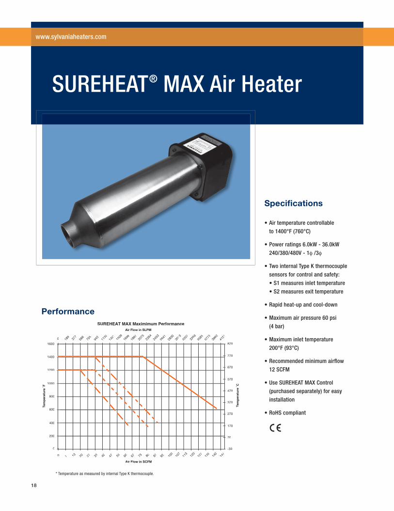
Performance
• Air temperature controllable
to 1400°F (760°C)
• Power ratings 3.0kW - 8.0kW
240V - 1φ
• Two internal Type K thermocouple
sensors for control and safety:
• S1 measures inlet temperature
• S2 measures exit temperature
• Rapid heat-up and cool-down
• Maximum air pressure 60 psi
(4 bar)
• Maximum inlet temperature
200°F (93°C)
• Use SUREHEAT JET Control
(purchased separately) for easy
installation
• Recommended minimum airfl ow 2 SCFM (57 SLPM)
• RoHS compliant
Specifi cations
SUREHEAT® JET Air Heater
www.sylvaniaheaters.com
* Temperature as measured by internal Type K thermocouple.
17
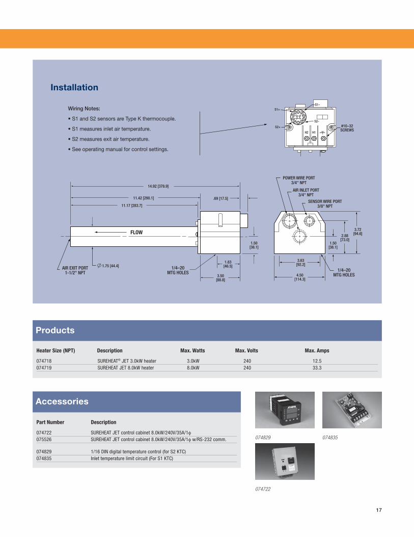
Part Number Description
074722 SUREHEAT JET control cabinet 8.0kW/240V/35A/1φ075526 SUREHEAT JET control cabinet 8.0kW/240V/35A/1φ w/RS-232 comm.
074829 1/16 DIN digital temperature control (for S2 KTC)074835 Inlet temperature limit circuit (For S1 KTC)
Heater Size (NPT) Description Max. Watts Max. Volts Max. Amps
074718 SUREHEAT® JET 3.0kW heater 3.0kW 240 12.5074719 SUREHEAT JET 8.0kW heater 8.0kW 240 33.3
Products
Wiring Notes:
• S1 and S2 sensors are Type K thermocouple.
• S1 measures inlet air temperature.
• S2 measures exit air temperature.
• See operating manual for control settings.
S2+
S1+S1-
H2 H1
#10–32SCREWS
S2-
1/4–20MTG HOLES
1/4–20MTG HOLES
14.92 [378.9]
.69 [17.5]
1.50[38.1]
3.50[88.8]
1.83[46.5]
11.17 [283.7]
11.42 [290.1]
FLOW
POWER WIRE PORT3/4" NPT
SENSOR WIRE PORT3/8" NPT
AIR INLET PORT3/4" NPT
3.72[94.6]
3.63[92.2]
2.88[73.0]
1.50[38.1]
4.50[114.3]
AIR EXIT PORT1-1/2" NPT
1.75 [44.4]
Installation
Accessories
074829 074835
074722
18
0
200
400
600
800
1000
1200
1400
1600
-30
70
170
270
370
470
570
670
770
870
0 189
377
566
755
943
1132
1321
1509
1698
1887
2075
2264
2453
2641
2830
3019
3207
3962
3773
3585
3396
4151
0 7 13 20 27 33 40 47 53 60 67 73 80 87 93 100
107
113
140
133
127
120
147
Air Flow in SCFM
Tem
per
atu
re ˚
FTT T e
mp
erat
ure
˚C
TT
Air Flow in SLPM
SUREHEAT MAX Maximimum Performance
Performance
• Air temperature controllable
to 1400°F (760°C)
• Power ratings 6.0kW - 36.0kW
240/380/480V - 1φ /3φ
• Two internal Type K thermocouple
sensors for control and safety:
• S1 measures inlet temperature
• S2 measures exit temperature
• Rapid heat-up and cool-down
• Maximum air pressure 60 psi
(4 bar)
• Maximum inlet temperature
200°F (93°C)
• Recommended minimum airfl ow
12 SCFM
• Use SUREHEAT MAX Control
(purchased separately) for easy
installation
• RoHS compliant
Specifi cations
SUREHEAT® MAX Air Heater
www.sylvaniaheaters.com
* Temperature as measured by internal Type K thermocouple.
19
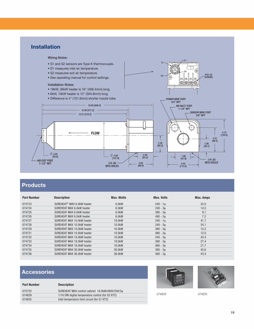
Part Number Description
075725 SUREHEAT MAX control cabinet 18.0kW/480V/25A/3φ074829 1/16 DIN digital temperature control (for S2 KTC)074835 Inlet temperature limit circuit (for S1 KTC)
Part Number Description Max. Watts Max. Volts Max. Amps
074723 SUREHEAT® MAX 6.0kW heater 6.0kW 240 - 1φ 25.0074724 SUREHEAT MAX 6.0kW heater 6.0kW 240 - 3φ 14.5074725 SUREHEAT MAX 6.0kW heater 6.0kW 380 - 3φ 9.1074726 SUREHEAT MAX 6.0kW heater 6.0kW 480 - 3φ 7.2074727 SUREHEAT MAX 10.0kW heater 10.0kW 240 - 1φ 41.7074728 SUREHEAT MAX 10.0kW heater 10.0kW 240 - 3φ 24.1074729 SUREHEAT MAX 10.0kW heater 10.0kW 380 - 3φ 15.2074731 SUREHEAT MAX 10.0kW heater 10.0kW 480 - 3φ 12.0074732 SUREHEAT MAX 18.0kW heater 18.0kW 240 - 3φ 43.4074733 SUREHEAT MAX 18.0kW heater 18.0kW 380 - 3φ 27.4074734 SUREHEAT MAX 18.0kW heater 18.0kW 480 - 3φ 21.7074735 SUREHEAT MAX 30.0kW heater 30.0kW 380 - 3φ 45.6074736 SUREHEAT MAX 36.0kW heater 36.0kW 480 - 3φ 43.4
Products
Installation
Accessories
074829 074835
Wiring Notes:
• S1 and S2 sensors are Type K thermocouple. • S1 measures inlet air temperature. • S2 measures exit air temperature. • See operating manual for control settings.
Installation Notes: • 18kW, 36kW heater is 16" (406.4mm) long. • 6kW, 10kW heater is 12" (304.8mm) long. • Difference is 4" (101.6mm) shorter nozzle tube.
S1-
#10–32SCREWS
4.75[120.6]
3.51[89.2]
1.90[48.1]
1.88[47.8]
4.45[113.0]
2.38[60.3]
2.49[63.2]
16.00 [406.4]
12.49 [317.2]
12.21 [310.2]
3.50[88.9]
AIR EXIT PORT1-1/2" NPT 1/4–20
MTG HOLES
1/4–20MTG HOLES
POWER WIRE PORT3/4" NPT
SENSOR WIRE PORT3/8" NPT
AIR INLET PORT1-1/4" NPT
FLOW
S2-
S2+
S1+
H2H3 H1
4.00[101.6]
2.00[50.8]
20
0
200
400
600
800
1000
1200
1400
1600
1800
0
100
200
300
400
500
600
700
800
900
1000
Tem
per
atu
re ˚
FTT Te
mp
erat
ure
˚C
Air Flow in SLPM
SUREHEAT MAX HT Maximimum Performance
0 189
377
566
755
943
1132
1321
1509
1698
1887
2075
2264
2453
2641
2830
3019
3207
3962
3773
3585
3396
4151
0 7 13 20 27 33 40 47 53 60 67 73 80 87 93 100
107
113
140
133
127
120
147
Air Flow in SCFM
SUREHEATAA ® MAX-HT
Standard SUREHEATAA ® MAXAA
30kW
36kW
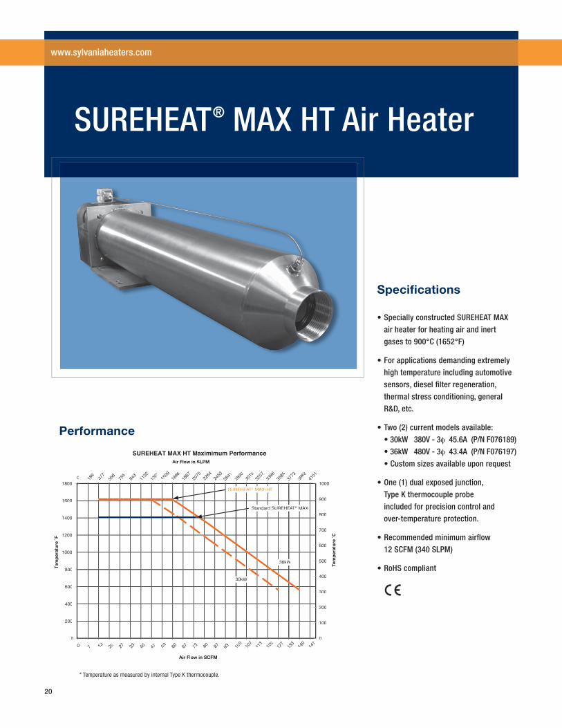
Performance
• Specially constructed SUREHEAT MAX
air heater for heating air and inert
gases to 900°C (1652°F)
• For applications demanding extremely
high temperature including automotive
sensors, diesel fi lter regeneration,
thermal stress conditioning, general
R&D, etc.
• Two (2) current models available:
• 30kW 380V - 3φ 45.6A (P/N F076189)
• 36kW 480V - 3φ 43.4A (P/N F076197)
• Custom sizes available upon request
• One (1) dual exposed junction,
Type K thermocouple probe
included for precision control and
over-temperature protection.
• Recommended minimum airfl ow
12 SCFM (340 SLPM)
• RoHS compliant
Specifi cations
SUREHEAT® MAX HT Air Heater
www.sylvaniaheaters.com
* Temperature as measured by internal Type K thermocouple.
21
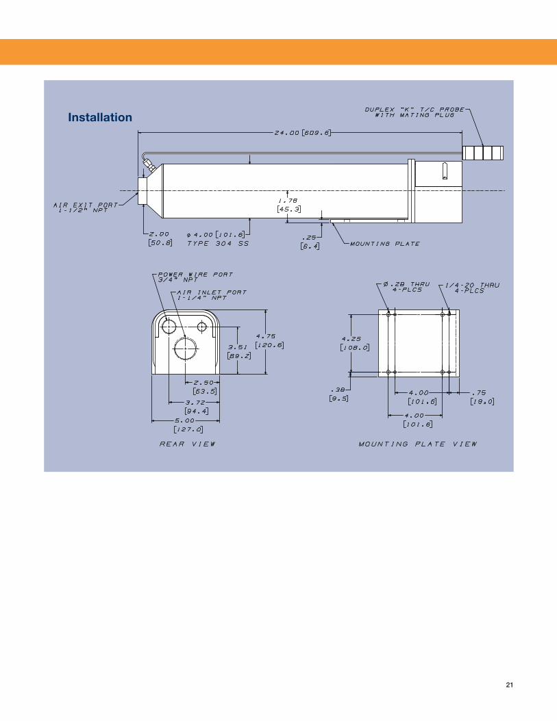
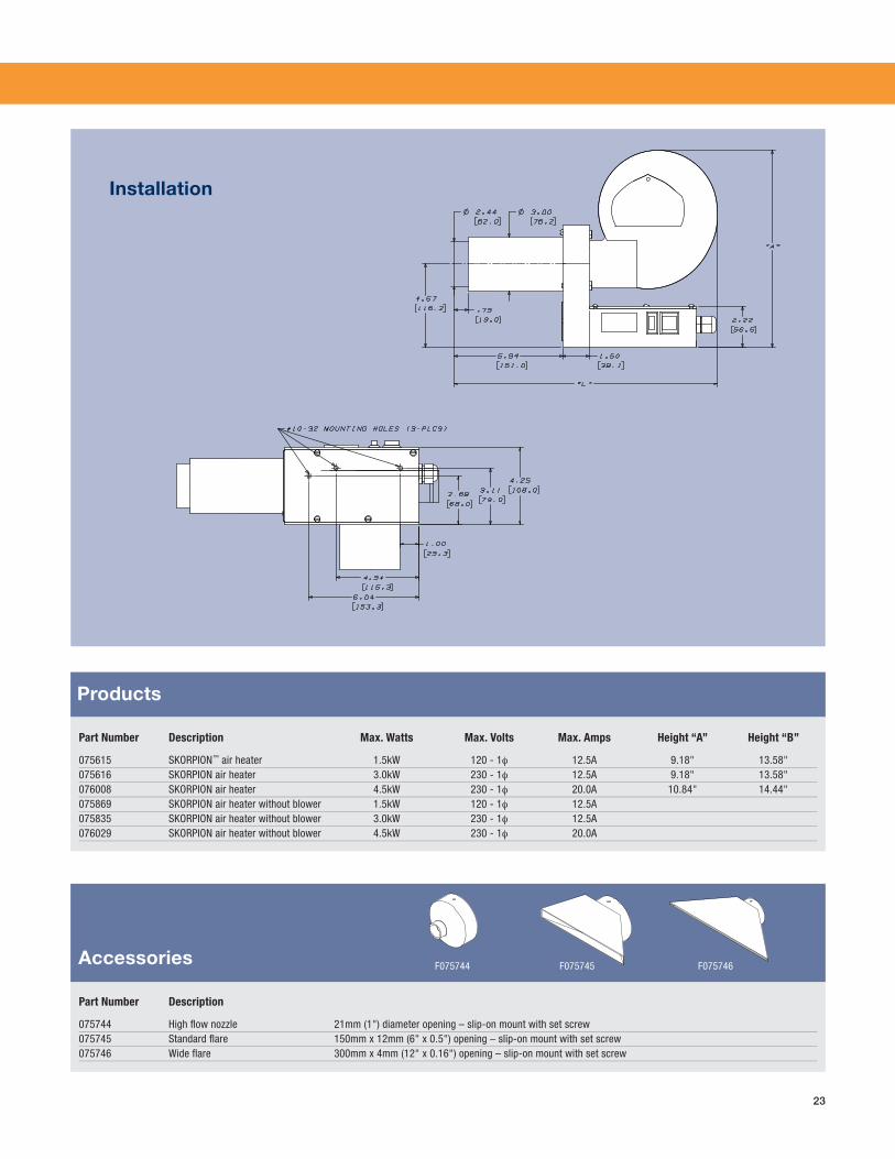
Installation
22
Tem
per
atu
re ˚
F
Tem
per
atu
re ˚
C
Air Flow in SLPM
SKORPION Maximimum Performance
Air Flow in SCFM
-30
70
170
270
370
470
570
670
770
870
0
200
400
600
800
1000
1200
1400
1600
2 5 8 12 15 18 22 25 28 32 35 38 42 45 48 52 55 58
47 142
236
330
425
519
613
708
802
896
991
1085
1179
1274
1368
1462
1557
1651
Air Damper Open beyond this point.
4.5kW Heater
r3.0kW Heater
1.5kW Heater
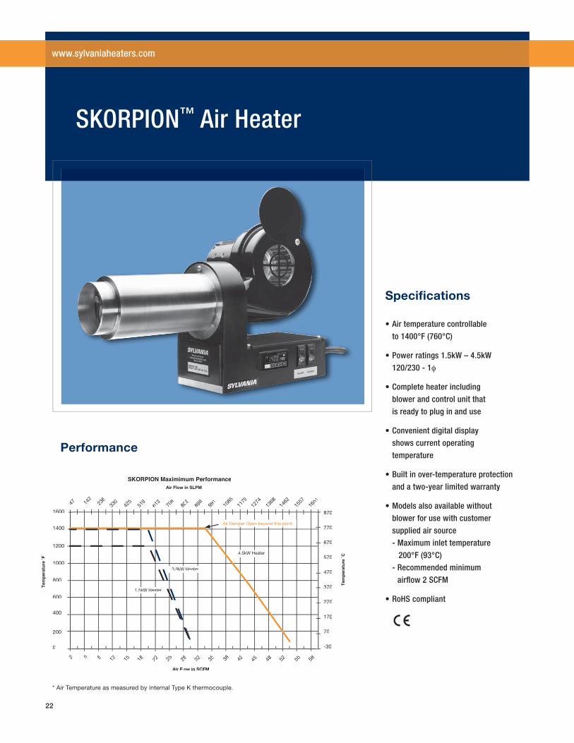
Performance
• Air temperature controllable
to 1400°F (760°C)
• Power ratings 1.5kW – 4.5kW
120/230 - 1φ
• Complete heater including
blower and control unit that
is ready to plug in and use
• Convenient digital display
shows current operating
temperature
• Built in over-temperature protection
and a two-year limited warranty
• Models also available without
blower for use with customer
supplied air source
- Maximum inlet temperature
200°F (93°C)
- Recommended minimum
airfl ow 2 SCFM
• RoHS compliant
Specifi cations
SKORPION™ Air Heater
www.sylvaniaheaters.com
* Air Temperature as measured by internal Type K thermocouple.
23
Part Number Description
075744 High fl ow nozzle 21mm (1") diameter opening – slip-on mount with set screw075745 Standard fl are 150mm x 12mm (6" x 0.5") opening – slip-on mount with set screw075746 Wide fl are 300mm x 4mm (12" x 0.16") opening – slip-on mount with set screw
Part Number Description Max. Watts Max. Volts Max. Amps Height “A” Height “B”
075615 SKORPION™ air heater 1.5kW 120 - 1φ 12.5A 9.18" 13.58"075616 SKORPION air heater 3.0kW 230 - 1φ 12.5A 9.18" 13.58"076008 SKORPION air heater 4.5kW 230 - 1φ 20.0A 10.84" 14.44"075869 SKORPION air heater without blower 1.5kW 120 - 1φ 12.5A075835 SKORPION air heater without blower 3.0kW 230 - 1φ 12.5A076029 SKORPION air heater without blower 4.5kW 230 - 1φ 20.0A
Products
Accessories
Installation
F075744 F075745 F075746
24
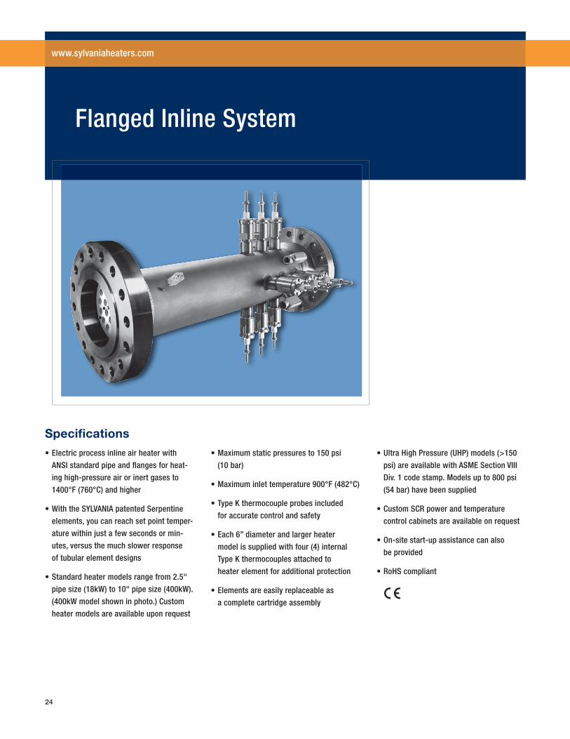
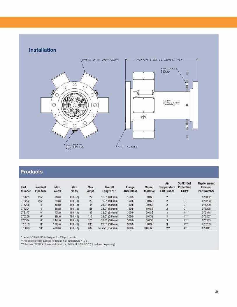
• Electric process inline air heater with
ANSI standard pipe and fl anges for heat-
ing high-pressure air or inert gases to
1400°F (760°C) and higher
• With the SYLVANIA patented Serpentine
elements, you can reach set point temper-
ature within just a few seconds or min-
utes, versus the much slower response
of tubular element designs
• Standard heater models range from 2.5"
pipe size (18kW) to 10" pipe size (400kW).
(400kW model shown in photo.) Custom
heater models are available upon request
• Maximum static pressures to 150 psi
(10 bar)
• Maximum inlet temperature 900°F (482°C)
• Type K thermocouple probes included
for accurate control and safety
• Each 6” diameter and larger heater
model is supplied with four (4) internal
Type K thermocouples attached to
heater element for additional protection
• Elements are easily replaceable as
a complete cartridge assembly
• Ultra High Pressure (UHP) models (>150
psi) are available with ASME Section VIII
Div. 1 code stamp. Models up to 800 psi
(54 bar) have been supplied
• Custom SCR power and temperature
control cabinets are available on request
• On-site start-up assistance can also
be provided
• RoHS compliant
Specifi cations
Flanged Inline System
www.sylvaniaheaters.com
25
Air SUREHEAT Replacement Part Nominal Max. Max. Max. Overall Flange Vessel Temperature Protection ElementNumber Pipe Size Watts Volts Amps Length "L" ANSI Class Material KTC Probes KTC’s Part Number
072631 2.5" 18kW 480 - 3φ 22 16.0" (406mm) 150lb 304SS 2 0 076062076202 2.5" 24kW 480 - 3φ 29 16.0" (406mm) 150lb 304SS 2 0 076203076208 4" 36kW 480 - 3φ 44 23.0" (584mm) 150lb 304SS 2 0 076209076204 4" 48kW 480 - 3φ 58 23.0" (584mm) 150lb 304SS 2 0 076205073377 6" 72kW 480 - 3φ 87 23.0" (584mm) 300lb 304SS 3 4*** 073378076206 6" 96kW 480 - 3φ 116 23.0" (584mm) 300lb 304SS 3 4*** 076207073384 8" 144kW 480 - 3φ 175 23.0" (584mm) 300lb 304SS 3 4*** 073385073153 8" 192kW 480 - 3φ 235 23.0" (584mm) 300lb 304SS 3 4*** 073253076013* 10" 400kW 480 - 3φ 482 52.75" (1340mm) 300lb 316HSS 2** 4*** 076041
* Heater P/N F076013 is designed for 300 psi operation. ** Two duplex probes supplied for total of 4 air temperature KTC's. *** Requires SUREHEAT four-zone limit circuit, SYLVANIA P/N F073262 (purchased separately).
Products
Installation

26
27
Reference Data
www.sylvaniaheaters.com
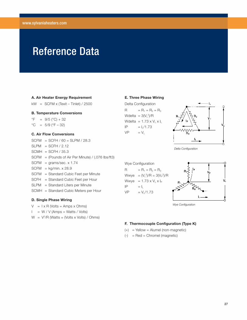
A. Air Heater Energy Requirement
kW = SCFM x (Texit – Tinlet) / 2500
B. Temperature Conversions
°F = 9/5 (°C) + 32
°C = 5/9 (°F – 32)
C. Air Flow Conversions
SCFM = SCFH / 60 = SLPM / 28.3
SLPM = SCFH / 2.12
SCMH = SCFH / 35.3
SCFM = (Pounds of Air Per Minute) / (.076 lbs/ft3)
SCFM = grams/sec. x 1.74
SCFM = kg/min. x 28.9
SCFM = Standard Cubic Feet per Minute
SCFH = Standard Cubic Feet per Hour
SLPM = Standard Liters per Minute
SCMH = Standard Cubic Meters per Hour
D. Single Phase Wiring
V = I x R (Volts = Amps x Ohms)
I = W / V (Amps = Watts / Volts)
W = V2/R (Watts = (Volts x Volts) / Ohms)
E. Three Phase Wiring
Delta Confi guration
R = R1 = R2 = R3
Wdelta = 3(VL2)/R
Wdelta = 1.73 x VL x ILIP = IL/1.73
VP = VL
Wye Confi guration
R = R1 = R2 = R3
Wwye = (VL2)/R = 3(VP
2)/R
Wwye = 1.73 x VL x IPIP = ILVP = VL/1.73
F. Thermocouple Confi guration (Type K)
(+) = Yellow = Alumel (non-magnetic)
(-) = Red = Chromel (magnetic)
© 2
009
OSR
AM S
YLVA
NIA
9/
09
OSRAM SYLVANIA 131 Portsmouth AvenueExeter, NH 03833 USATel. 800-258-8290In NH 603-772-1072www.sylvaniaheaters.com
OSRAM SYLVANIA Headquarters 100 Endicott Street Danvers, MA 01923 USA(978) 777-1900www.sylvania.com
The information and recommendations contained in this publication are based upon data collected by OSRAM SYLVANIA and believed to be correct. However, no guarantee or warranty of any kind, expressed or implied, is made with respect to the information contained herein, and OSRAM SYLVANIA assumes no responsibility for the results of the use of products and processes described herein. No statements or recommendations made herein are to be construed as inducements to infringe any relevant patent, now or hereafter in existence.
SYLVANIA is a registered trademark of OSRAM SYLVANIA Inc.SEE THE WORLD IN A NEW LIGHT is a registered trademark of OSRAM SYLVANIA Inc.SUREHEAT is a registered trademark of OSRAM SYLVANIA Inc. SKORPION is a trademark of OSRAM SYLVANIA Inc.
Prin
ted
on re
cycl
ed p
aper
with
50%
recy
cled
con
tent
incl
udin
g 25
% P
ost C
onsu
mer
Was
te a
nd is
aci
d an
d el
emen
tal c
hlor
ine
free.
PMC013 9/09
For orders and product information: