swl electric chain hoists - swl lifting...
TRANSCRIPT

SWLElectric Chain
Hoists
BLFD-008-1B L F D - 0 1 2 - 1B L F D - 0 1 6 - 1BLFD-024-1BLFD-032-2BLFD-048-2
MODELS
Presents
A div of The Dressor Group Ltd.
Part and Operations Manual for
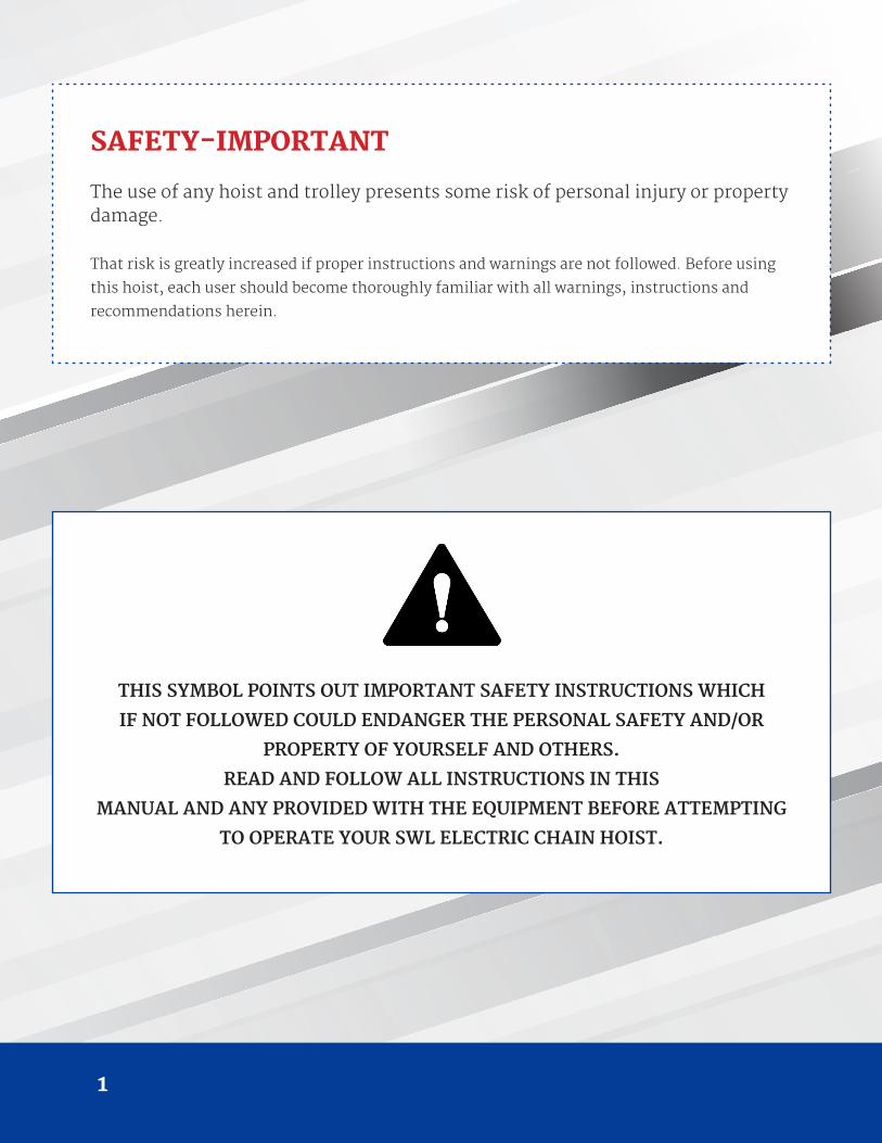
SAFETY-IMPORTANT
The use of any hoist and trolley presents some risk of personal injury or property damage.
That risk is greatly increased if proper instructions and warnings are not followed. Before using
this hoist, each user should become thoroughly familiar with all warnings, instructions and
recommendations herein.
THIS SYMBOL POINTS OUT IMPORTANT SAFETY INSTRUCTIONS WHICH
IF NOT FOLLOWED COULD ENDANGER THE PERSONAL SAFETY AND/OR
PROPERTY OF YOURSELF AND OTHERS.
READ AND FOLLOW ALL INSTRUCTIONS IN THIS
MANUAL AND ANY PROVIDED WITH THE EQUIPMENT BEFORE ATTEMPTING
TO OPERATE YOUR SWL ELECTRIC CHAIN HOIST.
1
T H E D R E S S O R G R O U P
Safety-Importan t .................................................................................................................................................................................................................................................................................................................................................................... 1
1. Foreword ................................................................................................................................................................................................................................................................................................................................................................................................ 3
2. Main Specification .................................................................................................................................................................................................................................................................................... 4
2 . 1 Specification .................................................................................................................................................................................................................................................................................................................................... 4
2.2 Mechanical Classification (Grade) and Life .............................................................................................................................................................................................................. 5
2.3 Safety D evice .............................................................................................................................................................................................................................................................................................................................. 6
2. 4 Specification and Dimensions ................................................................................................................................................................................................................................................................ 7
3.Safety Rules .................................................................................................................................................................................................................................................................................................................................................................................... 8
4. Installation ................................................................................................................................................................................................................................................................................................................................................................................... 11
4.1 Unpacking Information ....................................................................................................................................................................................................................................................................................... 11
4 .2 Voltage ..................................................................................................................................................................................................................................................................................................................................................... 11
4.3 Installation ........................................................................................................................................................................................................................................................................................................................................ 11
5.Operation ............................................................................................................................................................................................................................................................................................................................................................................................ 13
6.Maintenance and Inspection .............................................................................................................................................................................................................................................................................................................. 14
6.1 Maintenance .................................................................................................................................................................................................................................................................................................................................... 14
6.2 Inspection ........................................................................................................................................................................................................................................................................................................................................... 14
7.Troub leshooting ................................................................................................................................................................................................................................................................................................................................................................ 17
7.1 Wiring Diagrams .................................................................................................................................................................................................................................................................................................................. 17
7.2 Troubleshooting and Remedial Action ............................................................................................................................................................................................................................ 20
8.Drawings and Parts List ............................................................................................................................................................................................................................................................................................................................... 22
3
1. FOREWORDThis manual contains important information to help you properly install, operate and maintain the SWL
electric chain hoist for maximum performance, economy and safety.
Please study its contents thoroughly before putting the electric Chain hoist into operation. By practicing
correct operation, procedures and by carrying out the preventative maintenance recommendations, you will
be assured of dependable service. In order to help us to supply correct spare parts quickly, please always
specify,
(1) Hoist model
(2) Serial number
(3) Part number, plus the description.
Our goal at SWL Lifting Products is to establish a long term customer satisfaction policy with you “Our
Customer”
Should you have any queries, please contact:
( Please ask for a company’s stamp from your local agent)
T H E D R E S S O R G R O U P
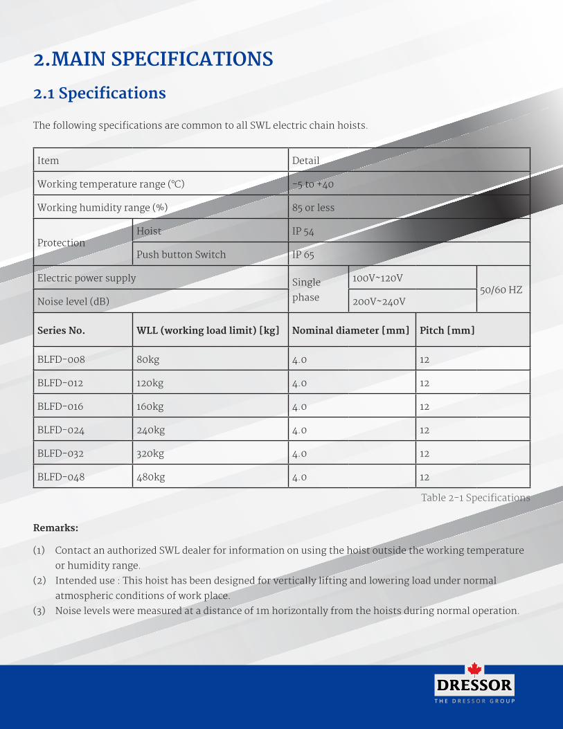
2.MAIN SPECIFICATIONS
2.1 Specifications
The following specifications are common to all SWL electric chain hoists.
Item Detail
Working temperature range (°C) -5 to +40
Working humidity range (%) 85 or less
ProtectionHoist IP 54
Push button Switch IP 65
Electric power supply Single
phase
100V~120V50/60 HZ
Noise level (dB) 200V~240V
Series No. WLL (working load limit) [kg] Nominal diameter [mm] Pitch [mm]
BLFD-008 80kg 4.0 12
BLFD-012 120kg 4.0 12
BLFD-016 160kg 4.0 12
BLFD-024 240kg 4.0 12
BLFD-032 320kg 4.0 12
BLFD-048 480kg 4.0 12
Table 2-1 Specifications
Remarks:
(1) Contact an authorized SWL dealer for information on using the hoist outside the working temperature
or humidity range.
(2) Intended use : This hoist has been designed for vertically lifting and lowering load under normal
atmospheric conditions of work place.
(3) Noise levels were measured at a distance of 1m horizontally from the hoists during normal operation.
5
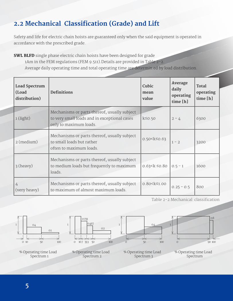
2.2 Mechanical Classification (Grade) and Lift
Safety and life for electric chain hoists are guaranteed only when the said equipment is operated in
accordance with the prescribed grade.
SWL BLFD single phase electric chain hoists have been designed for grade
1Am in the FEM regulations (FEM 9.511).Details are provided in Table 2-2.
Average daily operating time and total operating time are determin ed by load distribution.
Load Spectrum
(Load
distribution)
Definitions
Cubic
mean
value
Average
daily
operating
time [h]
Total
operating
time [h]
1 (light)
Mechanisms or parts thereof, usually subject
to very small loads and in exceptional cases
only to maximum loads.
k≤0.50 2 - 4 6300
2 (medium)
Mechanisms or parts thereof, usually subject
to small loads but rather
often to maximum loads.
0.50<k≤0.631 - 2 3200
3 (heavy)
Mechanisms or parts thereof, usually subject
to medium loads but frequently to maximum
loads.
0.63<k ≤0.80 0.5 - 1 1600
4
(very heavy)
Mechanisms or parts thereof, usually subject
to maximum of almost maximum loads.
0.80<k≤1.000.25 - 0.5 800
Table 2-2 Mechanical classification
% Operating time Load Spectrum 1
% Operating time Load Spectrum 2
% Operating time Load Spectrum 3
% Operating time Load Spectrum
0
1 0.4
0.1
10 50 100 0
1
0.733
0.467
0.2
16.7 33.3 50 100 0
1 0.4
50 100 0
1
0.8
90 100
T H E D R E S S O R G R O U P
2.3 Safety Devices
(1) Mechanical load brake
The mechanical load brake can hold a full capacity load independent of motor brake. This brake assures that
load does not accelerate while being lowered.
(2) Hook and hook latch
The hook is drop-forged from high tensile steel and heat treated for strength and toughness. The button
hook is capable of 360° swivel and fitted with safety latch to
ensure safe lifting.
(3) Limit Switches
Upper and lower limit switches are fitted for switching off power automatically in case of over lifting or over
lowering.
(4) Emergency stop device
This button is used to stop the hoist in an emergency situation. It is red, mushroom type button, located in
the uppermost position on the pendant. When pressed, power to the equipment is switch off and button
locks automatically. Turning it to the right will release the lock and to enable
re-starting.
(5) Shock protection
It cannot run, when you push the button for anti-direction in “UP” or “DOWN” running. You must
wait over 1 second.
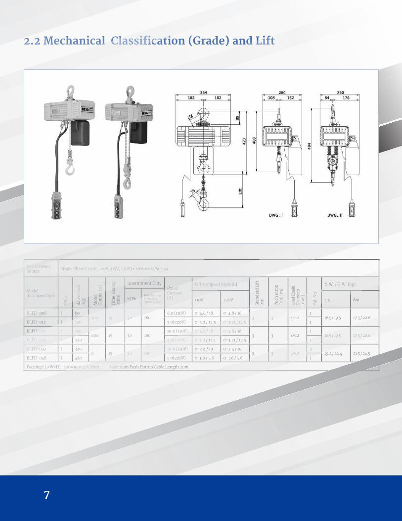
2.2 Mechanical Classification (Grade) and Lift
Rated Power Source Single Phase ( 110V, 220V, 115V, 230V) ± 10% 60Hz/50Hz9
Model (Dual Speed Type)
DW
G.
Rat
ed L
oad
[kg]
Mot
orO
utp
ut [
w]
Tim
e R
atin
g[m
in]
Intermittent DutyRated Current [A]
Lifting Speed [m/min]
Stan
dard
Lif
t [m
]
Puch
utt
on
Cor
d [m
]
Load
Ch
ain
D
iam
eter
[m
m]
Fall
No.
N.W. / G.W. [kg]
ED%Max Starting Frequency [times / min] 110V 220V 3m 6m
BLFD-008 I 80300 15 30 180
6.0 (110V) 0-4.8 / 18 0-4.8 / 183 3 4×12
116.5 / 19.5 17.5 / 20.6
BLFD-012 I 120 3.0(220V) 0-3.2 / 12.5 0-3.21 / 12.5 1
BLFD-016 I 160600 15 30 180
10.0 (110V) 0-4.8 / 18 0-4.8 / 183 3 4×12
116.5 / 19.5 17.5 / 20.6
BLFD-024 I 240 5.0(220V) 0-3.2 / 11.2 0-3.21 / 12.5 1
BLFD-032 I 3206 15 30 180
10.0 (110V) 0-2.4 / 19 0-2.4 / 193 3 4×12
219.4 / 22.4 21.5 / 24.5
BLFD-048 I 480 5.0(220V) 0-1.6 / 5.6 0-1.6 / 5.6 1
Packing ( L×W×H) : 500×390×205 [mm] Maximum Push Button Cable Length 20m
7
T H E D R E S S O R G R O U P
3. SAFETY RULES
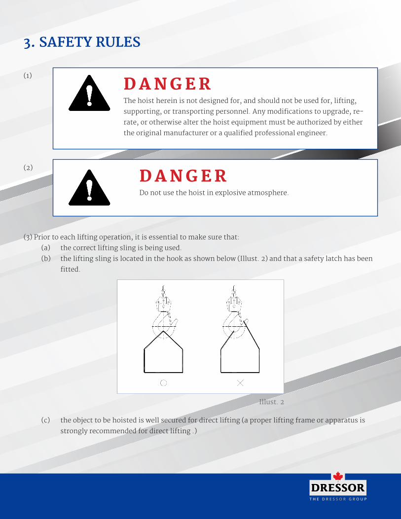
(3) Prior to each lifting operation, it is essential to make sure that:
(a) the correct lifting sling is being used.
(b) the lifting sling is located in the hook as shown below (Illust. 2) and that a safety latch has been
fitted.
(c) the object to be hoisted is well secured for direct lifting (a proper lifting frame or apparatus is
strongly recommended for direct lifting .)
D A N G E RThe hoist herein is not designed for, and should not be used for, lifting,
supporting, or transporting personnel. Any modifications to upgrade, re-
rate, or otherwise alter the hoist equipment must be authorized by either
the original manufacturer or a qualified professional engineer.
D A N G E RDo not use the hoist in explosive atmosphere.
(1)
(2)
Illust. 2
9
(4) Firm and steady button operation is required, never push the button switch intermittently.
(5) Always avoid excessive inching operation.
(6) Always make sure the hoist motor completely stops before reversing.
(7) Always leave the pendant button switch cable and bottom hook load chain vertically static after completion of operation, never leave them at any position, which may allow them swing or slip.
(8) Sling must be applied to load evenly and centrally to ensure correct balance. Never lift any object which
is insecure or out of balance.
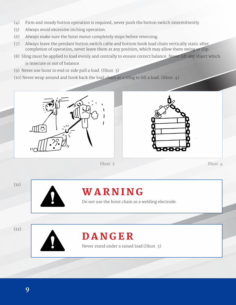
(9) Never use hoist to end or side pull a load. (Illust. 3)
(10) Never wrap around and hook back the load chain as a sling to lift a load. (Illust. 4)
Illust. 3 Illust. 4
W A R N I N GDo not use the hoist chain as a welding electrode.
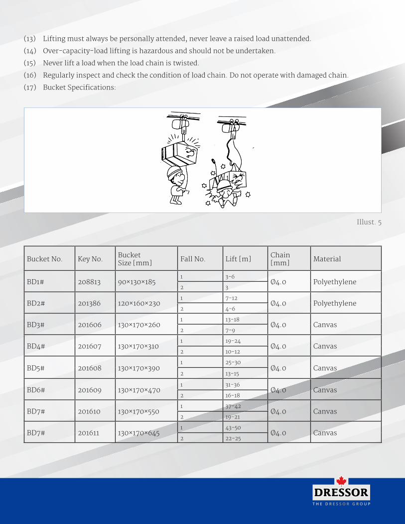
D A N G E RNever stand under a raised load (Illust. 5)
(11)
(12)
T H E D R E S S O R G R O U P
(13) Lifting must always be personally attended, never leave a raised load unattended.
(14) Over-capacity-load lifting is hazardous and should not be undertaken.
(15) Never lift a load when the load chain is twisted.
(16) Regularly inspect and check the condition of load chain. Do not operate with damaged chain.
(17) Bucket Specifications:
Bucket No. Key No. BucketSize [mm] Fall No. Lift [m] Chain
[mm] Material
BD1# 208813 90×130×1851 3-6
Ø4.0 Polyethylene2 3
BD2# 201386 120×160×2301 7-12
Ø4.0 Polyethylene2 4-6
BD3# 201606 130×170×2601 13-18
Ø4.0 Canvas2 7-9
BD4# 201607 130×170×3101 19-24
Ø4.0 Canvas2 10-12
BD5# 201608 130×170×3901 25-30
Ø4.0 Canvas2 13-15
BD6# 201609 130×170×4701 31-36
Ø4.0 Canvas2 16-18
BD7# 201610 130×170×5501 37-42
Ø4.0 Canvas2 19-21
BD7# 201611 130×170×6451 43-50
Ø4.0 Canvas2 22-25
Illust. 5
11
4. INSTALLATION
4.1 Unpacking Information
After removing the hoist from its packing box, carefully inspect the external condition of the electrical
cables, contactor, gear box and motor casing for damage.
Check and ensure that these items are present.
Each hoist is supplied as standard with the following accessories.
1. Chain bucket 1 piece
2. Power cable 3 meters
3. Separated control cable with PBS and female plug 1 set
Table. 4-1
C A U T I O NIf power supply deviates from standard by more than ± 10%, abnormal
operation or damage to the motor may result. It is imperative to ensure
correct voltage supply before commencing operation.
W A R N I N GConnection to power supply before installation procedures having been
completed is strictly prohibited.
4.2 Voltage
4.3 Installation
T H E D R E S S O R G R O U P
Illust. 6
Illust. 7
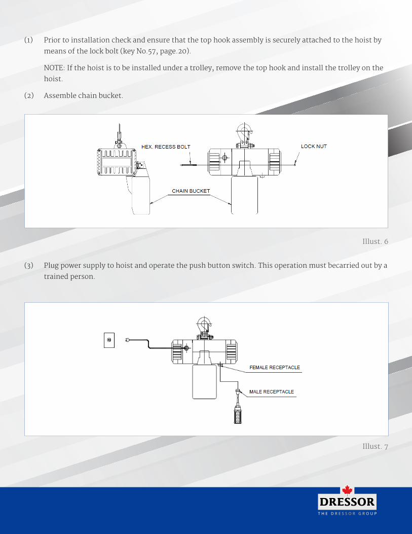
(3) Plug power supply to hoist and operate the push button switch. This operation must becarried out by a
trained person.
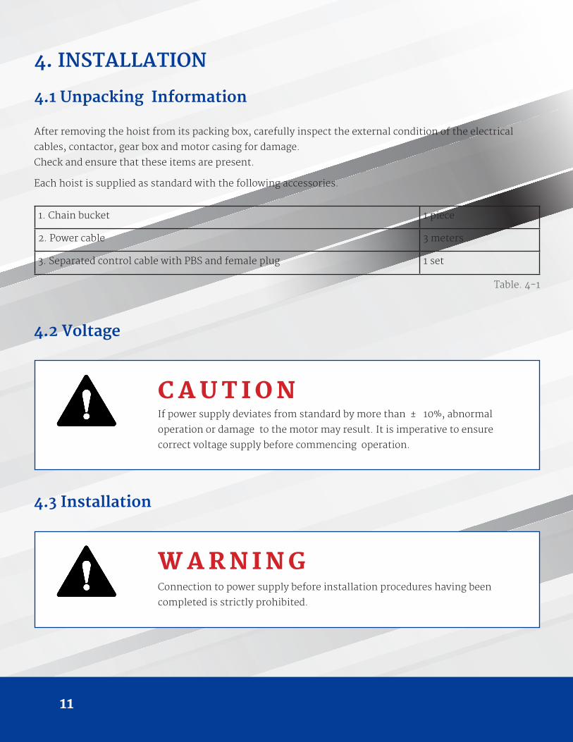
(1) Prior to installation check and ensure that the top hook assembly is securely attached to the hoist by
means of the lock bolt (key No.57, page.20).
NOTE: If the hoist is to be installed under a trolley, remove the top hook and install the trolley on the
hoist.
(2) Assemble chain bucket.
13
(4) Operation Test
(a) Firmly push switch button to lower load chain until the chain end buffer touches the limit
switch. Power should be cut off automatically.
(b) Firmly push switch button to check the collection of load chain into chain bucket.
(c) Check load chain lubrication. (It has been lubricated at our works, but the lubricant may dry out
during transportation) Any readily available lubricant is recommended. It is further advisable to
keep a small amount of lubricant in chain bucket to allow chain in oil bath.
(d) Check the emergency stop device function:
While holding down either or button on the push button switch, push the emergency stop
button. Check that the hook stops when the emergency stop button is pushed. Also, check the
hoist does not move in response to the push button switch. Finally, check that the emergency
stop device pops out when turned to the right and that operation can be resumed thereafter.
If the equipment fails to pass another above checks, check the wiring and automatic locking
function of the emergency stop device.
5. OPERATION
Since dealing with heavy loads may involve unexpected danger all of the “SAFETY RULES” (Ref 3.) must be
followed and the operator must be aware of the following points while using the hoist.
(1) On connection of power supply allow 15 seconds to initiate start up.
(2) The operator must have a clear and unobstructed view of the entire working area before operating the hoist.
(3) The operator must check that the entire working area is safe and secure before operating the hoist.
(4) When using the hoist with a plain trolley, the operator must take care to prevent excessive load swinging by sympathetic push trolley movements.
W A R N I N GSince dealing with heavy loads may involve unexpected danger all of the “SAFETY RULES” (Ref 3.) must be followed and the operator must be aware of the following points while using the hoist.

T H E D R E S S O R G R O U P
6.1 Maintenance
(1) Check the level of gear box lubricant after first 100 hours of operation, thereafter every 3 months and
lubricant accordingly. Lubricant use ISO VG460 or equivalent.
(2) Always keep the hoist unit dry and never misuse it in a manner likely to reduce its durability. (3) When
it is necessary to keep the unit outdoors, a protective covering should be fitted.
6.2 Inspection
(1) Daily inspection: Before starting daily operation, check the following,
(a) correct power supply.
(b) “Up” , “Down” and test runs under no load. (c) correct motor performance.
(d) no abnormal or excessive noise.
(e) no malfunction of the bottom hook safety latch.
(f) proper function of moving/turning parts, limit switches and brake. (g) well lubricated load chain.
6. MAINTENANCE AND INSPECTION
D A N G E RDo not perform maintenance on the hoist while it is carrying a load except
monthly checking for the brake, limit switch or slip clutch.
D A N G E RBefore performing maintenance do not forget to affix tags to the power
source and the push button switch reading : “DANGER”, “EQUIPMENT
BEING REPAIRED”.
15
(2) Monthly inspection
W A R N I N GAlways use the hoist manufacture’s recommended parts when repairing a hoist.
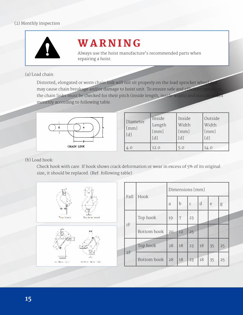
(a) Load chain:
Distorted, elongated or worn chain link will not sit properly on the load sprocket wheel and
may cause chain breakage and/or damage to hoist unit. To ensure safe and efficient operation,
the chain links must be checked for their pitch (inside length, inside width) and outside width
monthly according to following table.
(b) Load hook:
Check hook with care. If hook shows crack deformation or wear in excess of 5% of its original
size, it should be replaced. (Ref. following table)
Diameter
[mm]
[d]
Inside
Length
[mm]
[d]
Inside
Width
[mm]
[d]
Outside
Width
[mm]
[d]
4.0 12.0 5.0 14.0
Fall Hook
Dimensions [mm]
a b c d e g
1F
Top hook 19 7 23
Bottom hook 20 12 25
2F
Top hook 28 18 23 18 35 25
Bottom hook 28 18 23 18 35 25
T H E D R E S S O R G R O U P
(3) Annual inspection
(a) check gearing for any excessive wear or damage.
(b) replace gear box lubricant completely.
(c) check brake lining and ratchet pawl for any wear or damage.
(d) check operation of pawl spring.
(e) after reassembly of above check, lifting a load several times to ensure good performance of the
hoist before starting duty operation.
W A R N I N GYour dealer should be asked to perform this inspection.
17
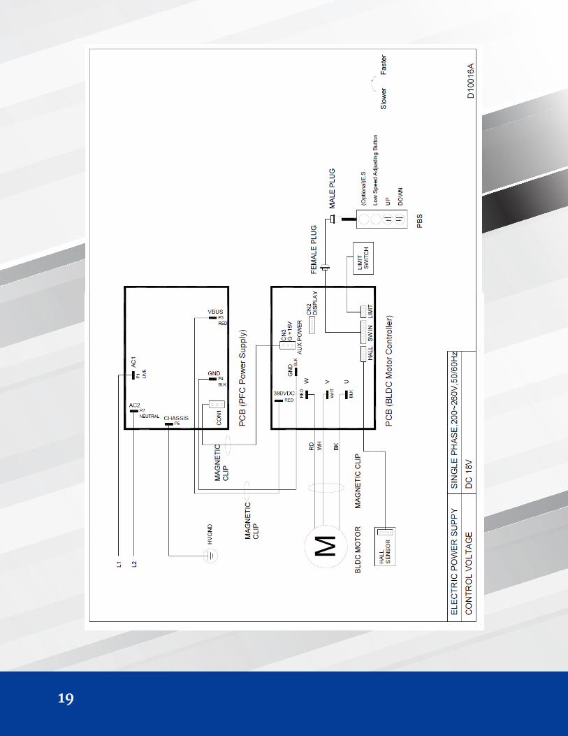
7. TROUBLESHOOTING
7.1 Wiring Diagrams
(1) 100V~120V – 1Ph – 50/60Hz power supply (with Emergency Stop) ……………………………………..............….………………………. 18
(2) 200V~260V – 1Ph – 50/60Hz power supply (with Emergency Stop) …………………………….…..............................…………… 19
The above listed wiring diagram for reference only.
The end user should refer to the wiring diagram stuck to the inside cover of electric housing.
Our electric specifications can be done according to following.
(a) 1 – Phase
(b) 50Hz or 60Hz
(c) 100V~120V or 200V~260V
Warranty Details
1. Warranty Period : One year for Mechanical Spare Parts after purchase the product.
2. Non-Warranty Scope:
a. Electrical Spare Parts (ex. Contactor, Pendant, Phase Error Relay, etc.)
b. Expense Spare Parts (ex. Chain Bucket, Brake Lining, etc.)
c. Damage caused by unsuitable operation.
(ex. Galvanize plant, Chemical Plant, Dye-work, etc. )
d. Damage caused by operate on the wrong electric voltage.
e. Damage caused by user amend the product.
f. Damage caused by natural disaster.
3. Warranty period is one year from date of invoice for parts only. See distributor for their labour
warranty policy.
Spare Parts Repair and Replacement.
(circumstance stated in detail No. 2 are not included.)

T H E D R E S S O R G R O U P
19
T H E D R E S S O R G R O U P
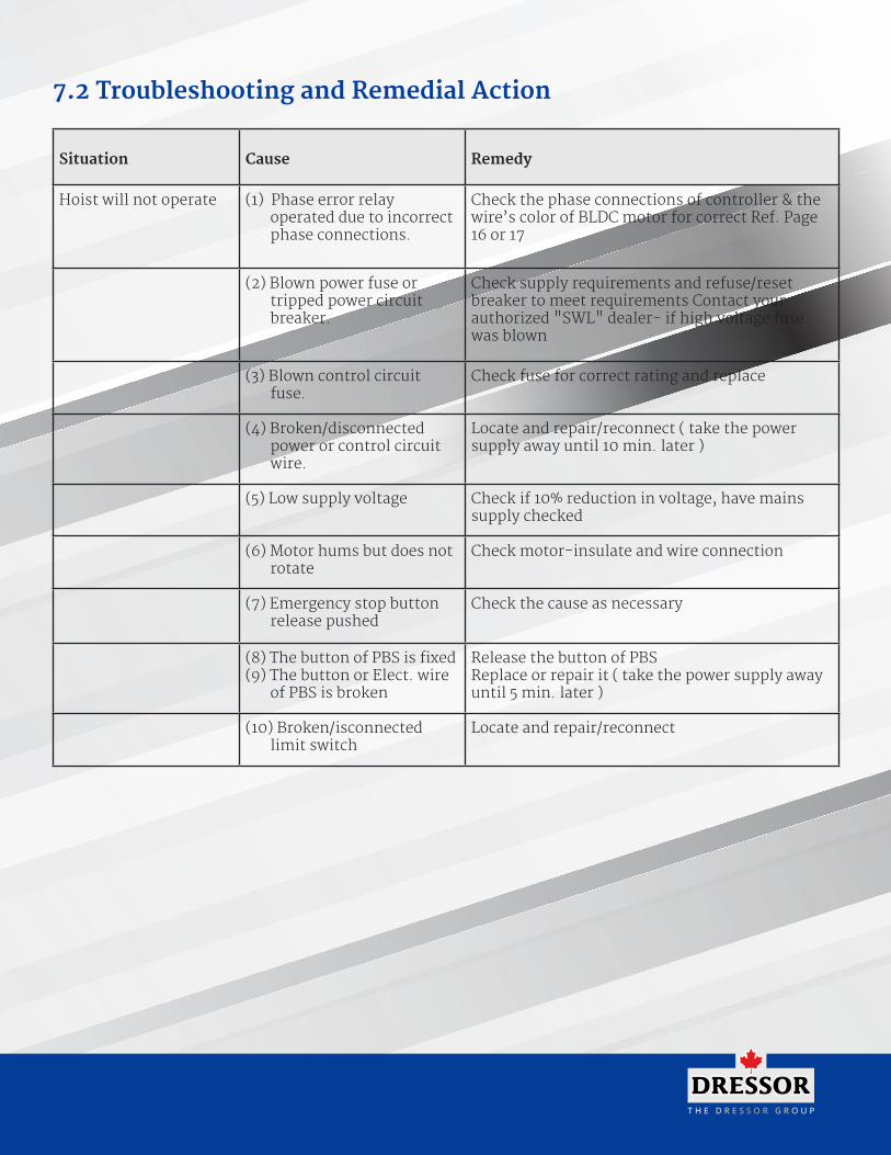
7.2 Troubleshooting and Remedial Action
Situation Cause Remedy
Hoist will not operate (1) Phase error relay operated due to incorrect phase connections.
Check the phase connections of controller & the wire’s color of BLDC motor for correct Ref. Page 16 or 17
(2) Blown power fuse or tripped power circuit breaker.
Check supply requirements and refuse/reset breaker to meet requirements Contact your authorized "SWL" dealer- if high voltage fuse was blown
(3) Blown control circuit fuse.
Check fuse for correct rating and replace
(4) Broken/disconnected power or control circuit wire.
Locate and repair/reconnect ( take the power supply away until 10 min. later )
(5) Low supply voltage Check if 10% reduction in voltage, have mains supply checked
(6) Motor hums but does not rotate
Check motor-insulate and wire connection
(7) Emergency stop button release pushed
Check the cause as necessary
(8) The button of PBS is fixed(9) The button or Elect. wire
of PBS is broken
Release the button of PBSReplace or repair it ( take the power supply away until 5 min. later )
(10) Broken/isconnected limit switch
Locate and repair/reconnect
21
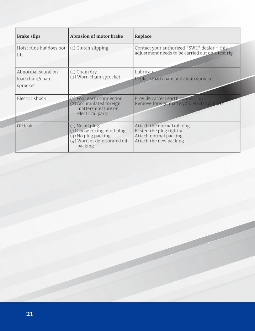
Brake slips Abrasion of motor brake Replace
Hoist runs but does not
lift
(1) Clutch slipping Contact your authorized "SWL" dealer – this adjustment needs to be carried out on a test rig
Abnormal sound on
load chain/chain
sprocket
(1) Chain dry(2) Worn chain sprocket
Lubricate
Replace load chain and chain sprocket
Electric shock (1) Poor earth connection(2) Accumulated foreign
matter/moisture on electrical parts
Provide correct earth connectionRemove foreign matter/dry electrical parts
Oil leak (1) No oil plug(2) Loose fitting of oil plug(3) No plug packing(4) Worn or deteriorated oil
packing
Attach the normal oil plug Fasten the plug tightly Attach normal packing Attach the new packing
T H E D R E S S O R G R O U P
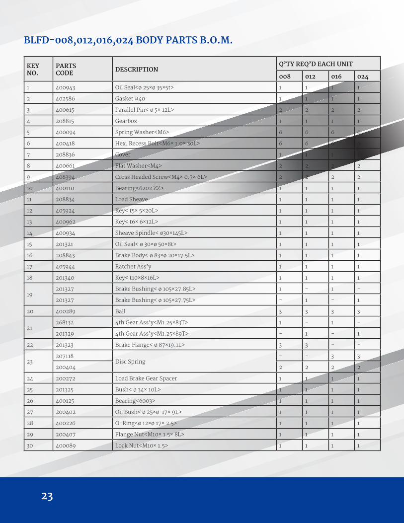
23
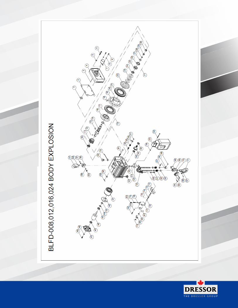
KEYNO.
PARTSCODE DESCRIPTION
Q’TY REQ’D EACH UNIT
008 012 016 024
1 400943 Oil Seal<ø 25×ø 35×5t> 1 1 1 1
2 402586 Gasket #40 1 1 1 1
3 400615 Parallel Pin< ø 5× 12L> 2 2 2 2
4 208815 Gearbox 1 1 1 1
5 400094 Spring Washer<M6> 6 6 6 6
6 400418 Hex. Recess Bolt<M6× 1.0× 30L> 6 6 6 6
7 208836 Cover 1 1 1 1
8 400661 Flat Washer<M4> 2 2 2 2
9 408394 Cross Headed Screw<M4× 0.7× 6L> 2 2 2 2
10 400110 Bearing<6202 ZZ> 1 1 1 1
11 208834 Load Sheave 1 1 1 1
12 405924 Key< t5× 5×20L> 1 1 1 1
13 400962 Key< t6× 6×12L> 1 1 1 1
14 400934 Sheave Spindle< ø30×145L> 1 1 1 1
15 201321 Oil Seal< ø 30×ø 50×8t> 1 1 1 1
16 208843 Brake Body< ø 83×ø 20×17.5L> 1 1 1 1
17 405944 Ratchet Ass’y 1 1 1 1
18 201340 Key< t10×8×16L> 1 1 1 1
19201327 Brake Bushing< ø 105×27.85L> 1 - 1 -
201327 Brake Bushing< ø 105×27.75L> - 1 - 1
20 400289 Ball 3 3 3 3
21268132 4th Gear Ass’y<M1.25×83T> 1 - 1 -
201329 4th Gear Ass’y<M1.25×89T> - 1 - 1
22 201323 Brake Flange< ø 87×19.1L> 3 3 - -
23207118
Disc Spring- - 3 3
200404 2 2 2 2
24 200272 Load Brake Gear Spacer 1 1 1 1
25 201325 Bush< ø 34× 10L> 1 1 1 1
26 400125 Bearing<6003> 1 1 1 1
27 200402 Oil Bush< ø 25×ø 17× 9L> 1 1 1 1
28 400226 O-Ring<ø 12×ø 17× 2.5> 1 1 1 1
29 200407 Flange Nut<M10× 1.5× 8L> 1 1 1 1
30 400089 Lock Nut<M10× 1.5> 1 1 1 1
BLFD-008,012,016,024 BODY PARTS B.O.M.
T H E D R E S S O R G R O U P
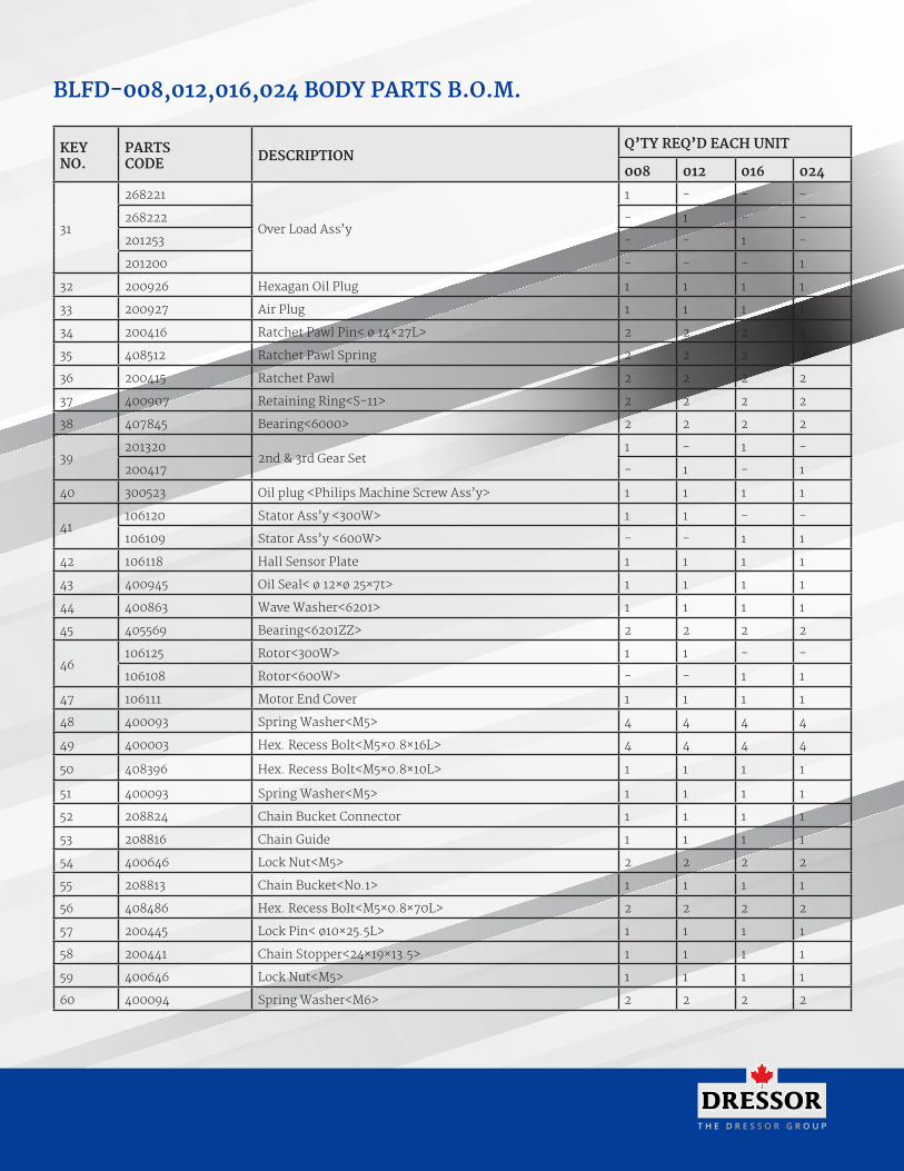
KEYNO.
PARTSCODE DESCRIPTION
Q’TY REQ’D EACH UNIT
008 012 016 024
31
268221
Over Load Ass’y
1 - - -
268222 - 1 - -
201253 - - 1 -
201200 - - - 1
32 200926 Hexagan Oil Plug 1 1 1 1
33 200927 Air Plug 1 1 1 1
34 200416 Ratchet Pawl Pin< ø 14×27L> 2 2 2 2
35 408512 Ratchet Pawl Spring 2 2 2 2
36 200415 Ratchet Pawl 2 2 2 2
37 400907 Retaining Ring<S-11> 2 2 2 2
38 407845 Bearing<6000> 2 2 2 2
39201320
2nd & 3rd Gear Set1 - 1 -
200417 - 1 - 1
40 300523 Oil plug <Philips Machine Screw Ass’y> 1 1 1 1
41106120 Stator Ass’y <300W> 1 1 - -
106109 Stator Ass’y <600W> - - 1 1
42 106118 Hall Sensor Plate 1 1 1 1
43 400945 Oil Seal< ø 12×ø 25×7t> 1 1 1 1
44 400863 Wave Washer<6201> 1 1 1 1
45 405569 Bearing<6201ZZ> 2 2 2 2
46106125 Rotor<300W> 1 1 - -
106108 Rotor<600W> - - 1 1
47 106111 Motor End Cover 1 1 1 1
48 400093 Spring Washer<M5> 4 4 4 4
49 400003 Hex. Recess Bolt<M5×0.8×16L> 4 4 4 4
50 408396 Hex. Recess Bolt<M5×0.8×10L> 1 1 1 1
51 400093 Spring Washer<M5> 1 1 1 1
52 208824 Chain Bucket Connector 1 1 1 1
53 208816 Chain Guide 1 1 1 1
54 400646 Lock Nut<M5> 2 2 2 2
55 208813 Chain Bucket<No.1> 1 1 1 1
56 408486 Hex. Recess Bolt<M5×0.8×70L> 2 2 2 2
57 200445 Lock Pin< ø10×25.5L> 1 1 1 1
58 200441 Chain Stopper<24×19×13.5> 1 1 1 1
59 400646 Lock Nut<M5> 1 1 1 1
60 400094 Spring Washer<M6> 2 2 2 2
BLFD-008,012,016,024 BODY PARTS B.O.M.

25
KEYNO.
PARTSCODE DESCRIPTION
Q’TY REQ’D EACH UNIT
008 012 016 024
61 400006 Hex. Recess Bolt<M6×1.0×16L> 2 2 2 2
62 408485 Spring 2 2 2 2
63 200442 Buffer Steel Plate <t4×25.5> 4 4 4 4
64 408329 Hex. Recess Bolt<M5×0.8×20L> 2 2 2 2
65 200445 Lock Pin< ø10×25.5L> 1 1 1 1
66 407463 Parallel Pin< ø 8×25L> 1 1 1 1
67 200480 Safe Latch Ass’y 2 2 2 2
68 400646 Lock Nut<M5> 3 3 3 3
69 201371I Bottom Hook Cover Set 2 2 2 2
70 400830 Thrust Bearing 1 1 1 1
71 201372I Bottom Hook 1 1 1 1
72 208825 Collision Block 1 1 1 1
73 400188 Retaining Ring <S-10> 2 2 2 2
74 404416 O-Ring< ø8×ø 10.8×1.5> 1 1 1 1
75 208822 Limit Control Shaft 1 1 1 1
76 405571 Lubricated Bearing 1 1 1 1
77 208819 Limit End Plate 1 1 1 1
78 208820 Compressing Block 2 2 2 2
79 408510 Limit Spring 2 2 2 2
80 400587 Threaded Stud<M8×1.25×10L> 2 2 2 2
81 400093 Spring Washer<M5> 2 2 2 2
82 400417 Hex. Recess Bolt<M5×0.8×20L> 2 2 2 2
83 300577 Limit Switch 2 2 2 2
84 208823 Limit Washer 1 1 1 1
85 208821 Limit Pawl 1 1 1 1
86 200432 Top Hook Suspension<t20×37×39L> 1 1 1 1
87 200433 Top Hook lock bolt<ø12×29.5L> 2 2 2 2
88 200456 Top Hook 1 1 1 1
89 400095 Spring Washer<M8> 2 2 2 2
90 400088 Lock Nut<M8×1.25> 2 2 2 2
91 208827 Lock Bolt< ø 12/M12x1.75x85L> 1 1 1 1
92 400084 Hex. Nut<M12×1.75> 1 1 1 1
93 400610 Cotter Pin<ø3×30L> 1 1 1 1
BLFD-008,012,016,024 BODY PARTS B.O.M.

T H E D R E S S O R G R O U P
BLFD-008,012,016,024 BODY PARTS B.O.M.

27
KEYNO.
PARTSCODE DESCRIPTION
Q’TY REQ’D EACH UNIT
032 048
1 400943 Oil Seal< ø 25×ø 35×5t> 1 1
2 402586 Gasket #40 1 1
3 400615 Parallel Pin< ø 5×12> 2 2
4 208815 Gearbox 1 1
5 400094 Spring Washer<M6> 6 6
6 400418 Hex. Recess Bolt<M6×1.0×30L> 6 6
7 208836 Cover 1 1
8 400661 Flat Washer<M4> 2 2
9 408394 Cross Headed Screw<M4×0.7×6L> 2 2
10 400110 Bearing<6202 ZZ> 1 1
11 208834 Load Sheave 1 1
12 405924 Key< t5×5×20L> 1 1
13 400962 Key< t6×6×12L> 1 1
14 201219 Sheave Spindle< ø30×145L> 1 1
15 400934 Oil Seal< ø 30×ø 50×8t> 1 1
16 201321 Brake Body< ø 83×ø 20×17.5L> 1 1
17 208843 Ratchet Ass’y 1 1
18 405944 Key< t10×8×16L> 1 1
19201340 Brake Bushing< ø 105×27.85L> 1 -
201327 Brake Bushing< ø 105×27.75L> - 1
20 400289 Ball 3 3
21268132 4th Gear Ass’y<M1.25×83T> 1 -
201329 4th Gear Ass’y<M1.25×89T> - 1
22 201323 Brake Flange< ø 87×19.1L> 1 1
23 200404 Disc Spring 1 -
24 200272 Load Brake Gear Spacer 3 3
25 201325 Bush< ø 34×10L> 2 2
26 400125 Bearing<6003> 1 1
27 200402 Oil Bush< ø 25×ø 17×9L> 1 1
28 400226 O-Ring<ø12×ø17×2.5> 1 1
29 200407 Flange Nut<M10×1.5×8L> 1 1
30 400089 Lock Nut <M10×1.5> 1 1
31201253
Over Load Ass’y1 -
201200 - 1
32 200926 Hexagan Oil Plug 1 1
33 200927 Air Plug 1 1
BLFD-032,048 BODY PARTS B.O.M.

T H E D R E S S O R G R O U P
KEYNO.
PARTSCODE DESCRIPTION
Q’TY REQ’D EACH UNIT
032 048
34 200416 Ratchet Pawl Pin< ø 14×27L> 2 2
35 408512 Ratchet Pawl Spring 2 2
36 200415 Ratchet Pawl 2 2
37 400907 Retaining Ring<S-11> 2 2
38 407845 Bearing<6000> 2 2
39201320
2nd & 3rd Gear Set1 -
200417 - 1
40 408396 Hex. Recess Bolt<M5×0.8×10L> 1 1
41 400093 Spring Washer<M5> 1 1
42 208824 Chain Bucket Connector 1 1
43 400646 Lock Nut<M5> 2 2
44 208813 Chain Bucket<No.1> 1 1
45 408486 Hex. Recess Bolt<M5×0.8×70L> 2 2
46 208816 Chain Guide 1 1
47 400094 Spring Washer<M6> 2 2
48 400006 Hex. Recess Bolt<M6×1.0×16L> 2 2
49 200442 Buffer Steel Plate <t4×25.5> 4 4
50 408485 Spring 3 3
51 200445 Lock Pin< ø10×25.5L> 1 1
52 200441 Chain Stopper<24×19×13.5> 1 1
53 400646 Lock Nut<M5> 1 1
54 408407 Threaded Stud<M4×0.7×4L> 1 1
55 407462 Parallel Pin <ø5×25L> 1 1
56 208839 Load Bracket 1 1
57 400093 Spring Washer<M5> 4 4
58 405019 Hex. Recess Bolt<M5×0.8×15L> 4 4
59 408329 Hex. Recess Bolt<M5×0.8×20L> 3 3
60 207069 Bottom Block Cover A 1 1
61 200361 Sprocket 1 1
62 408058 Needle Bearing <HK1412> 2 2
63 200322 Sprocket Axle 1 1
64 400295 Spring Pin <ø3×10L> 1 1
65 207071 Bottom Block Cover B 1 1
66 400646 Nylon Nut<M5> 3 3
67 200221 End Spacer 1 1
68 200212 Half Spacer 2 2
BLFD-032,048 BODY PARTS B.O.M.

29
KEYNO.
PARTSCODE DESCRIPTION
Q’TY REQ’D EACH UNIT
032 048
69 408057 Thrust Bearing <51103> 1 1
70 200367 Bottom Hook Ass'y 1 1
71 400300 Safety Latch Ass'y 2 2
72 300523 Oil plug <Philips Machine Screw Ass’y> 1 1
73 106109 Stator Ass’y <600W> 1 1
74 106118 Hall Sensor Plate 1 1
75 400945 Oil Seal< ø 12×ø 25×7t> 1 1
76 400863 Wave Washer<6201> 1 1
77 405569 Bearing<6201ZZ> 2 2
78 106108 Rotor<600W> 1 1
79 106111 Motor End Cover 1 1
80 400093 Spring Washer<M5> 4 4
81 400003 Hex. Recess Bolt<M5×0.8×16L> 4 4
82 208825 Collision Block 1 1
83 400188 Retaining Ring <S-10> 2 2
84 404416 O-Ring< ø8×ø 10.8×1.5> 1 1
85 208822 Limit Control Shaft 1 1
86 405571 Lubricated Bearing 1 1
87 400587 Threaded Stud<M8×1.25×10L> 2 2
88 408510 Limit Spring 2 2
89 208820 Compressing Block 2 2
90 208819 Limit End Plate 1 1
91 400093 Spring Washer<M5> 2 2
92 400417 Hex. Recess Bolt<M5×0.8×20L> 2 2
93 300577 Limit Switch 2 2
94 208823 Limit Washer 1 1
95 208821 Limit Pawl 1 1
96 208845 Top Hook Ass'y 1 1
97 208840 Washer 2 2
98 208841 Lock Bolt< ø 15/M12×1.75x85L> 1 1
99 400084 Hex. Nut<M12×1.75> 1 1
100 400610 Cotter Pin<ø3×30L> 1 1
BLFD-032,048 BODY PARTS B.O.M.

T H E D R E S S O R G R O U P

31
KEYNO.
PARTSCODE DESCRIPTION
Q’TY REQ’D EACH UNIT
100V~120V 200V~260V
300w 600w 300w 600w
1 400223 Cable Gland<M16> 1 1 1 1
2 408377 Cross Headed Screw<M3×0.5×12L> 6 6 6 6
3 405301 Spring Washer<M3> 6 6 6 6
4 300588 Holder A 1 1 1 1
5
300607PFC Power Supply
1 - - -
300606 - 1 - -
301677PFC Power Supply-D
- - 1 -
301675 - - - 1
6 400854 Spring Washer<M5> 8 8 8 8
7 408331 Hex. Recess Bolt<M5×0.8×50L> 8 8 8 8
8 402587 Gasket #41 2 2 2 2
9 300817 Fuse <5x20-5A> 1 1 2 2
10 400049 Cross Headed Screw<M4×0.7×8L> 8 8 8 8
11 400092 Spring Washer<M4> 8 8 8 8
12 300583 Electrical End Cover 1 1 1 1
13 402588 Gasket #42 1 1 1 1
14 300615 Female Receptacle 1 1 1 1
15 300616 Male Receptacle 1 1 1 1
16 300610 Push Button Switch 1 1 1 1
17 400087 Nut<M6x1.0> 1 1 1 1
18 404803 Eye Bolt< M6x1.0> 1 1 1 1
19 400841 Shackle 1 1 1 1
20 408601 Cross Headed Screw<M3×0.5×10L> 4 4 4 4
21300583
Electrical End Cover1 1 - -
301848 - - 1 1
22
300609DC Motor Controller
1 -
300599 - 1
301679DC Motor Controller-D
- - 1 -
301678 - - - 1
23 301849 Magnetic Clip 3 3 3 3
24 400048 Cross Headed Screw<M4×0.7×6L> 4 4 4 4
25 408561 Cross Headed Screw<M3×0.8×8L> 2 2 2 2
Notice: To match up No. 5 power board and No. 22 control board, even one of them needs to be replaced,please also replace another one at the same time.
BLFD-032,048 BODY PARTS B.O.M.

The Dressor Group Ltd.
400 Morobel Dr. Unit # 3Milton, ON L9T 4N6
1-905-636-9100 [email protected]
www.thedressorgroup.com