surface sensor tms - ouman oyouman.fi/documentbank/tms__data_brochure__en.pdfntc 10 pt 1000 ni 1000...
TRANSCRIPT
TMS
1
3
5
7
2
4
6
1
3
5
7
2
4
6
< 2s < 2s < 4s
+ 0,2 °C (0-70 °C) + 1 °C (0-70 °C) + 1 °C (0-70 °C)
NTC 10 Pt 1000 Ni 1000 LG
TMS / NTC10TMS / Pt1000TMS / Ni1000
Surface sensor
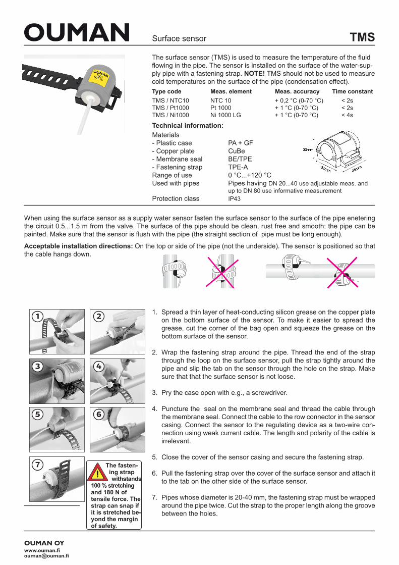
1. Spread a thin layer of heat-conducting silicon grease on the copper plate on the bottom surface of the sensor. To make it easier to spread the grease, cut the corner of the bag open and squeeze the grease on the bottom surface of the sensor.
2. Wrap the fastening strap around the pipe. Thread the end of the strap through the loop on the surface sensor, pull the strap tightly around the pipe and slip the tab on the sensor through the hole on the strap. Make sure that that the surface sensor is not loose.
3. Pry the case open with e.g., a screwdriver.
4. Puncture the seal on the membrane seal and thread the cable through the membrane seal. Connect the cable to the row connector in the sensor casing. Connect the sensor to the regulating device as a two-wire con-nection using weak current cable. The length and polarity of the cable is irrelevant.
5. Close the cover of the sensor casing and secure the fastening strap.
6. Pull the fastening strap over the cover of the surface sensor and attach it to the tab on the other side of the surface sensor.
7. Pipes whose diameter is 20-40 mm, the fastening strap must be wrapped around the pipe twice. Cut the strap to the proper length along the groove between the holes.
The surface sensor (TMS) is used to measure the temperature of the fluid flowing in the pipe. The sensor is installed on the surface of the water-sup-ply pipe with a fastening strap. NOTE! TMS should not be used to measure cold temperatures on the surface of the pipe (condensation effect).Type code Meas. element Meas. accuracy Time constant
Technical information:Materials- Plastic case PA + GF- Copper plate CuBe- Membrane seal BE/TPE- Fastening strap TPE-ARange of use 0 °C...+120 °C Used with pipes Pipes having DN 20...40 use adjustable meas. and up to DN 80 use informative measurementProtection class IP43
OUMAN OYwww.ouman.fi [email protected]
When using the surface sensor as a supply water sensor fasten the surface sensor to the surface of the pipe enetering the circuit 0.5...1.5 m from the valve. The surface of the pipe should be clean, rust free and smooth; the pipe can be painted. Make sure that the sensor is flush with the pipe (the straight section of pipe must be long enough).
Acceptable installation directions: On the top or side of the pipe (not the underside). The sensor is positioned so that the cable hangs down.
The fasten-ing strap withstands
100 % stretching and 180 N of tensile force. The strap can snap if it is stretched be-yond the margin of safety.
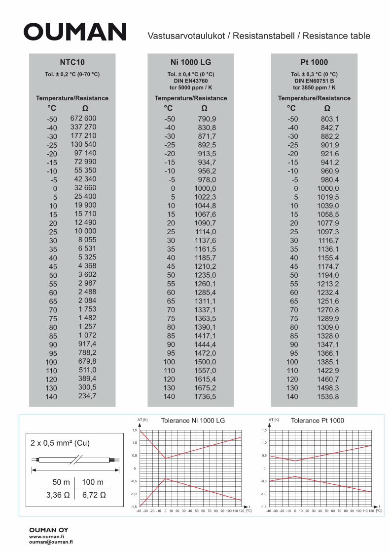
Tol. ± 0,2 °C (0-70 °C)
NTC10
°C-50-40-30-25-20-15-10
-505
101520253035404550556065707580859095
100110120130140
672 600337 270177 210130 54097 14072 99055 35042 34032 66025 40019 90015 71012 49010 000
8 0556 5315 3254 3683 6022 9872 4882 0841 7531 4821 2571 072917,4788,2679,8511,0389,4300,5234,7
ΩTemperature/Resistance
Ni 1000 LG
°C-50-40-30-25-20-15-10
-505
101520253035404550556065707580859095
100110120130140
790,9830,8871,7892,5913,5934,7956,2978,0
1000,01022,31044,81067,61090,71114,01137,61161,51185,71210,21235,01260,11285,41311,11337,11363,51390,11417,11444,41472,01500,01557,01615,41675,21736,5
Ω
Tol. ± 0,4 °C (0 °C)DIN EN43760
tcr 5000 ppm / K
Temperature/Resistance
Pt 1000
°C-50-40-30-25-20-15-10
-505
101520253035404550556065707580859095
100110120130140
Ω803,1842,7882,2901,9921,6941,2960,9980,4
1000,01019,51039,01058,51077,91097,31116,71136,11155,41174,71194,01213,21232,41251,61270,81289,91309,01328,01347,11366,11385,11422,91460,71498,31535,8
Tol. ± 0,3 °C (0 °C)DIN EN60751 Btcr 3850 ppm / K
Temperature/Resistance
OUMAN OY
Vastusarvotaulukot / Resistanstabell / Resistance table
1,5
1,0
0,5
-40 -30 -20 -10 0 10 20 30 40 50 60 70 80 90 100 110 120
-0,5
0
-1,0
-1,5[°C]
Tolerance Ni 1000 LG[K]T
t
1,5
1,0
0,5
-40 -30 -20 -10 0 10 20 30 40 50 60 70 80 90 100 110 120
-0,5
0
-1,0
-1,5[°C]
Tolerance Pt 1000
t
[K]T
50 m3,36 Ω 6,72 Ω
100 m
2 x 0,5 mm² (Cu)