suprasson pmax - suprasson pmax...
TRANSCRIPT
User's manual • Notice d'utilisation • Manual de usoBenutzerhandbuch • Manuale d'uso • Handleiding voor de gebruiker
Suprasson® PMax - Suprasson® PMax Lux
Illustrations
5 x 20230V:2x0,5AT11V:2x1AT
27 28 29 30
23 2421 25
26
BOOST31
32
3334
35
36
7
8 9 10 11 12
13a 13b 13c 14 15 16 17 18
19 20
37
38
40
41
43
39
42
22
13d
SUPPR
ASON LU
X
1
2
3
4
5
6
Illustrations
SUPRASSON
65
47
45 474644 48 49 50
5 x 20
230V:2x0,5AT
11V:2x1AT
Employer uniquement av
ecUse only with a 230 V fuse
un fusible de 230 V
Use only with
a 230V fuse
Employer uniq
uement avec
un fusible 230
V
51
52
53
54
1
1. Introduction
1. Introduction .................................................1
2. Installation ...................................................4
3. Starting and stopping the device .......................5
4. Using ultrasound mode....................................6
5. Maintenance.................................................7
6. Troubleshooting ............................................8
7. Technical specifications ................................ 10
The Suprasson® P Max is a multi-clinical piezoelectric ultrasound generator that enables treatment to be carried out in optimal aseptic and sterile conditions.
Suprasson® P Max is equipped with a Suprasson® handpiece (ultrasound).
Suprasson® P Max Lux is equipped with a Suprasson® Lux light handpiece (ultrasound).
General characteristics • Four ultrasound power ranges, each adjustable with 10
levels. • Color display for visual and ergonomic representation
of the power. • Boost function for instant selection of maximum power
in the selected mode. • Memory for each of the four power modes for easy
recall of a chosen power level. • Irrigation via the water supply with flow regulation on
the handpiece connector. • Main functions on the multifunction foot control. The Suprasson® P Max is a multifunction device for scaling, endodontic and periodontic treatment (according to option) in sterile or aseptic conditions.
Irrigation kit Available as an option • Irrigation kit comprising a peristaltic pump, an
irrigation line and two reservoirs for irrigation liquids. • Independent adjustment of irrigation flow. • Syringe effect. • Easy manual selection of the active reservoir or
complete shut-off. • Support for using bottles or pouches of sterile solution.
Parts included • A Suprasson® P Max or Suprasson® P Max Lux device
(depending on the option) • A mains cord
• A single or multifunction pedal foot control (depending on the option)
• Suprasson® or Suprasson® Lux handpiece depending on the version
• Tip kit depending on the sales version
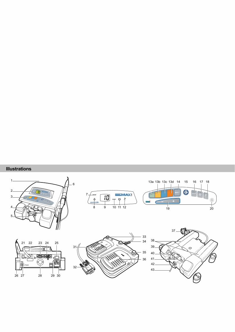
General view Refer to figure 1 on the fold-out part of the cover.
1. Rear panel 4. Button to control pump flow
2. Display area 5. Irrigation kit
3. Control keyboard 6. Suprasson® handpiece

2
1. Introduction
Front panel – Display
Includes display and indicators.
7. Boost indicator Lights when the BOOST function is activated.
8. Standby indicator Lights when the device is in standby mode (energy saving).
9. Display The display background color indicates:
• power on, the color indicator appears bluish white. Any other color signals a malfunction (see chapter “troubleshooting”);
• in use, the color displayed (green, yellow, blue and orange) corresponds to the color code of the ultrasound power range selected.
The figures displayed indicate:
• power on, the number 88 indicates the correct operation of the segments of the display. Any other value signals a malfunction of the indicator (see chapter “troubleshooting”).
• In use, the ultrasound power level (1 to 10) for the range selected, controlled by the keys (Ref. 19).
• when programming: - the length of time of inactivity before the
device enters standby mode; - for Suprasson® P Max Lux only, the length of
time before the light is switched off on the Suprasson® Lux handpiece, when ultrasound is no longer in use.
The following figure shows an example of the display, from left to right, power on, in use (setting the ultrasound power level) and when programming (light time limit).
10. Water supply indicator Lights when the key is pressed (ref. 16), and indicates irrigation via the drinking water supply.
11. Irrigation kit indicator Lights when the key is pressed (ref. 17), and indicates irrigation via one of the two reservoirs.
12. Spray or dry mode indicator Lights when the key is pressed (ref. 18).
Sensitive control panel
Is set out as follows:
13. Ultrasound power range keys Each yellow, green, blue and orange key corresponds to an ultrasound power range, from the weakest to the strongest as follows: • Green background: low power (ref. 13a). • Yellow background: intermediate power (ref. 13b). • Blue background: high power (ref. 13c). • Orange background: very high power (ref. 13d). The range selected: • a reminder is given by the color of the display
backlighting. • Is programmed in the factory at level 5 except for the
orange key which is programmed at level 1 and uses irrigation from the water supply.
The range may also be selected with the multifunction foot control (see chapter on the multifunction foot control pedal).
14. Boost Applies the power (value 10) of the selected range; the
lights up. A second press on the key exits the mode. This mode can also be accessed from the multifunction foot control (cannot be memorized and use must be occasional).
15. Memory key Memorizes a power level for each of the four power ranges, with the exception of switching on irrigation and Boost.
16. Water supply key Pressing this key selects drinking water (water supply) as the irrigation solution. The indicator lights up. Irrigation will only take place after the spray or dry key (ref. 18) is pressed; the rate of flow may be set via the handpiece connector. The two keys 16 and 17 are mutually exclusive and may be memorized.
17. Irrigation kit key Pressing this key selects the irrigation kit (optional). Irrigation will only take place after the spray or dry key (ref. 18) is pressed.
The rate of flow may be adjusted via the control knob on the pump. The two keys 16 and 17 are mutually exclusive and may be memorized.
18. Spray or dry key Switches irrigation on after keys 16 or 17 have been selected. The indicator (rep 12) lights up. A second press turns irrigation off.
19. The keys Reduce ( key ) or increase ( key) ultrasound power in the selected range. The values go from 1 to 10.
20. Button to enter or leave standby mode This button is mainly used for leaving standby mode. The initialization sequence is started. Only this button can be used to leave standby mode.
3
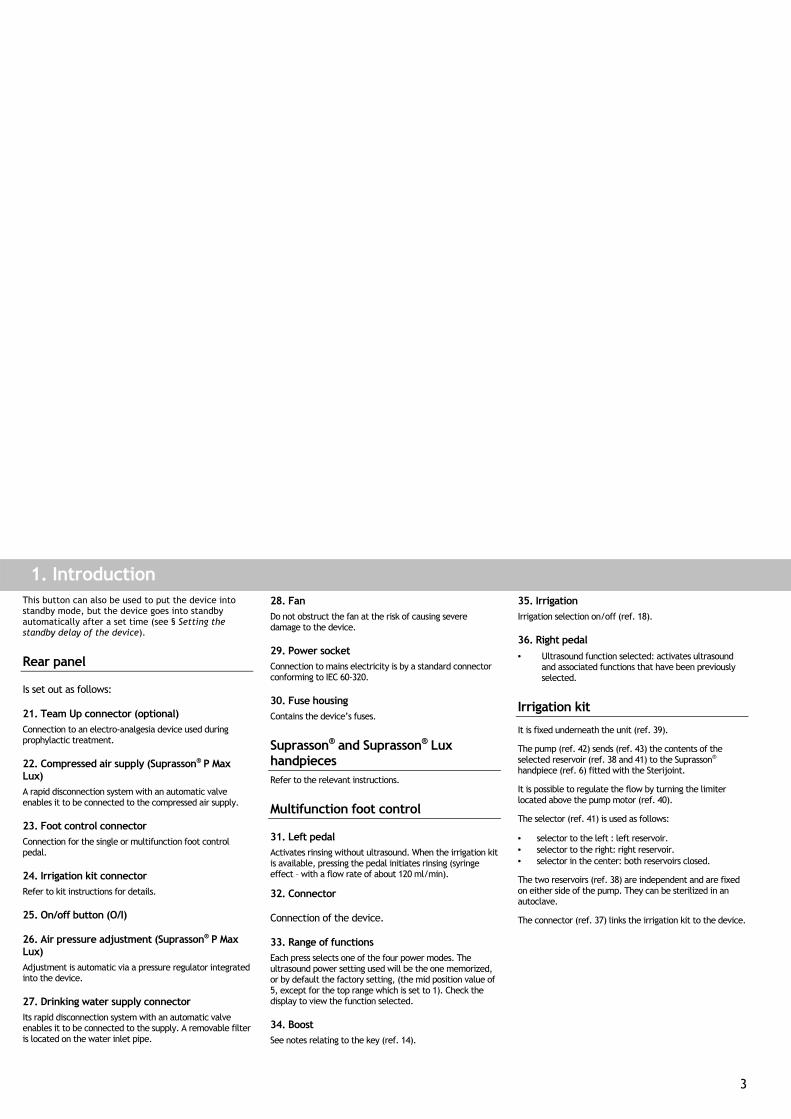
1. Introduction This button can also be used to put the device into standby mode, but the device goes into standby automatically after a set time (see § Setting the standby delay of the device).
Rear panel
Is set out as follows:
21. Team Up connector (optional) Connection to an electro-analgesia device used during prophylactic treatment.
22. Compressed air supply (Suprasson® P Max Lux) A rapid disconnection system with an automatic valve enables it to be connected to the compressed air supply.
23. Foot control connector Connection for the single or multifunction foot control pedal.
24. Irrigation kit connector Refer to kit instructions for details.
25. On/off button (O/I)
26. Air pressure adjustment (Suprasson® P Max Lux) Adjustment is automatic via a pressure regulator integrated into the device.
27. Drinking water supply connector Its rapid disconnection system with an automatic valve enables it to be connected to the supply. A removable filter is located on the water inlet pipe.
28. Fan Do not obstruct the fan at the risk of causing severe damage to the device.
29. Power socket Connection to mains electricity is by a standard connector conforming to IEC 60-320.
30. Fuse housing Contains the device’s fuses.
Suprasson® and Suprasson® Lux handpieces Refer to the relevant instructions.
Multifunction foot control
31. Left pedal Activates rinsing without ultrasound. When the irrigation kit is available, pressing the pedal initiates rinsing (syringe effect – with a flow rate of about 120 ml/min).
32. Connector
Connection of the device.
33. Range of functions Each press selects one of the four power modes. The ultrasound power setting used will be the one memorized, or by default the factory setting, (the mid position value of 5, except for the top range which is set to 1). Check the display to view the function selected.
34. Boost See notes relating to the key (ref. 14).
35. Irrigation Irrigation selection on/off (ref. 18).
36. Right pedal • Ultrasound function selected: activates ultrasound
and associated functions that have been previously selected.
Irrigation kit
It is fixed underneath the unit (ref. 39).
The pump (ref. 42) sends (ref. 43) the contents of the selected reservoir (ref. 38 and 41) to the Suprasson® handpiece (ref. 6) fitted with the Sterijoint.
It is possible to regulate the flow by turning the limiter located above the pump motor (ref. 40).
The selector (ref. 41) is used as follows:
• selector to the left : left reservoir. • selector to the right: right reservoir. • selector in the center: both reservoirs closed.
The two reservoirs (ref. 38) are independent and are fixed on either side of the pump. They can be sterilized in an autoclave.
The connector (ref. 37) links the irrigation kit to the device.
4
2. Installation
Recommendations For your safety, connections (water, air and electricity) should be carried out by an approved installer of dental equipment. The device requires the following connections (see technical specifications chapter).
Carry out the connection to the drinking water supply using an automatic cutoff valve of the Aquastop type, or to the dental chair water supply. Caution: always turn off the water supply when you leave the dental practice.
Setting up the equipment • Position the device in the place where it is going to
be used. • Connect the foot control (rep 32) to the connector on
the device (rep 23). • Connect the optional equipment (Team Up ref. 21,
irrigation kit ref. 24). • Connect the water supply pipe with its filter to the
connector located at the rear of the device (ref. 27). • Connect the air supply pipe to the rear of the device
(ref. 22) for Suprasson® P Max Lux. • Plug in the power socket (ref. 29) • Open the supply taps (water-air).
5
3. Starting and stopping the device This device should only be used by professionals (dental practictioners and hygienists). Before being used for the first time it is: • Imperative to clean, disinfect using alcohol or
disinfectant dental wipes and/or sterilize the accessories (casing of the device, handpiece, tips, keys, etc.).
• Recommended that the accessories should be plugged in and the spray operated for a few minutes to rinse the device’s internal water circuits.
Important: It is imperative that the water supply is turned off when leaving the dental practice.
Switching on the power 1. Set the power switch to the on position (I) (rep.
25). The device automatically goes into standby mode: the green indicator (ref. 8) on the front lights up. The device is in energy saving mode.
To operate 1. Press the (rep 20) key on the front of the
device The initialization phase lasting a few seconds is launched. The information displayed is as follows (any other values indicate malfunction): - Display: the figure 88 is displayed. - Background color of the display: bluish-
white. - Indicators: they all light up. At the end of the initialization phase, the display will show one of the following: - By default, low power mode is at level 5 on a
green background, no irrigation, water supply selected, light out in three seconds, (Suprasson® P Max Lux), enters standby mode automatically after nine minutes.
- Or the last configuration used. The device is ready to use.
Entering standby mode 1. Press the (rep 20) key.
- The front panel goes out. - The device is in energy saving mode. - The (rep. 8) indicator lights up.
Reminder: the device enters standby mode on its own after a predetermined time. See § Setting the device’s standby delay.
Leaving standby mode 1. Press the key (rep. 20).
The (rep. 8) indicator goes out and the device returns to the configuration being used before entering standby.
Changing the delays Delays refer to the time the light in the Suprasson® Lux handpiece stays on after ultrasound has been used, and the time taken before the device goes into standby mode after a period of inactivity.
Delay before the light goes out This function only applies to the Suprasson® P Max Lux. It specifies the length of time before the light goes out after ultrasound has been used (three seconds by default). To change this setting: 1. Put the device into standby ( key). 2. Press the boost and yellow keys together, then
the key while keeping the other keys depressed. The display will indicate “L” (Light) followed by a figure giving the current time delay in seconds.
3. Release the keys. 4. Set the time with the or keys.
The length of time can be set from 0 (L-) to nine seconds (L9). The new value comes into effect when the device is restarted. Therefore a light out time delay of 7 seconds will be displayed at “L7”.
Delay before the device enters standby mode This setting specifies the length of time before the device enters standby mode. To change this setting: 1. Put the device into standby ( key). 2. Press the yellow and blue keys together, then
the key, while keeping the other keys depressed. The display will indicate “A” (Stop) followed by a figure giving the current time delay in minutes.
3. Release the keys. 4. Set the time with the or keys.
The length of time can be set from no standby to 15 minutes. The new value comes into effect when the device is restarted.
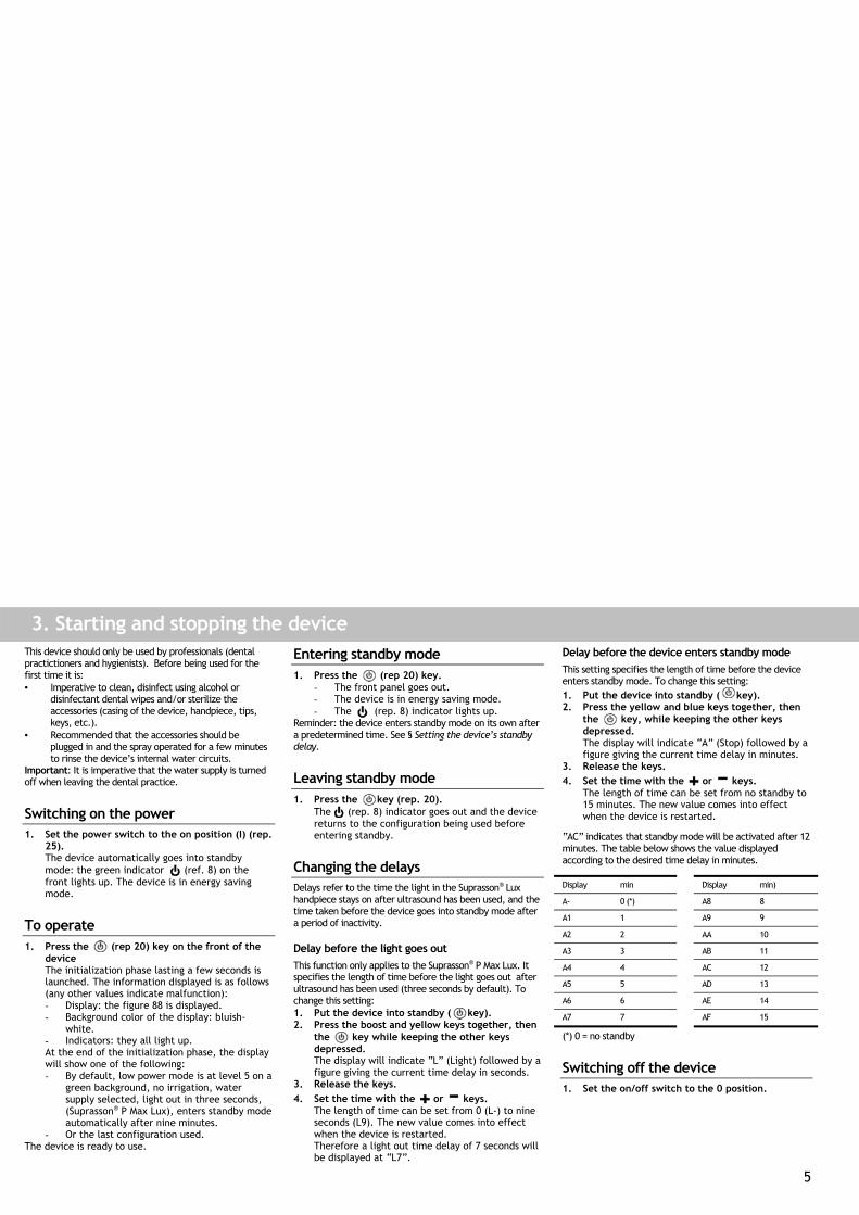
“AC” indicates that standby mode will be activated after 12 minutes. The table below shows the value displayed according to the desired time delay in minutes.
Display min Display min)
A- 0 (*) A8 8
A1 1 A9 9
A2 2 AA 10
A3 3 AB 11
A4 4 AC 12
A5 5 AD 13
A6 6 AE 14
A7 7 AF 15
(*) 0 = no standby
Switching off the device 1. Set the on/off switch to the 0 position.
6
4. Using ultrasound mode
Choosing the ultrasound power range 1. Select a power range by pressing one of the
four keys (green, yellow, blue, orange) (ref. 13) on the control panel:
By default the display indicates the color of the range selected at power setting 5 (1 for high power) and irrigation from the water supply.
Reminder: the ultrasound power range may be selected with the multifunction foot control.
Setting ultrasound power Incremental setting
1. Press the key to increase ultrasound power or the key to decrease it from 1 to 10, by steps of 1.
Setting the power to maximum ( ) 1. Press the key on the front of the unit (ref.
14) or the multifunction foot control (ref. 34) to set the power to maximum. The indicator lights up (ref. 7) and the display indicates the value of 10 in the selected range. To exit Boost mode, press the key on the front of the unit or press the multifunction foot control once more, or change the power range.
Spray or dry 1. Press the key on the face of the unit. (ref.
18) or the multifunction foot control (ref. 35) to activate irrigation. - In water supply mode, controlling the water
flow is via the connector ring on the Suprasson® handpiece (ref. 47).
- In irrigation kit mode, controlling the water flow is via the flow limiter located on the pump (ref. 40).
Memorizing the ultrasound power level 1. Select the desired power range (ref. 13). 2. Change the power level with the keys
(ref. 19). 3. Press the memory key . (ref. 15)
The power display shows “--” for one second to confirm memorization.
Recalling a level from memory 1. Press the key for the desired power range (ref.
13). The memorized value is displayed. Refer to the Tipbook for power settings of Satelec tips.
7
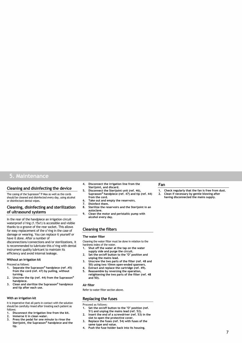
5. Maintenance
Cleaning and disinfecting the device The casing of the Suprasson® P Max as well as the cords should be cleaned and disinfected every day, using alcohol or disinfectant dental wipes.
Cleaning, disinfecting and sterilization of ultrasound systems
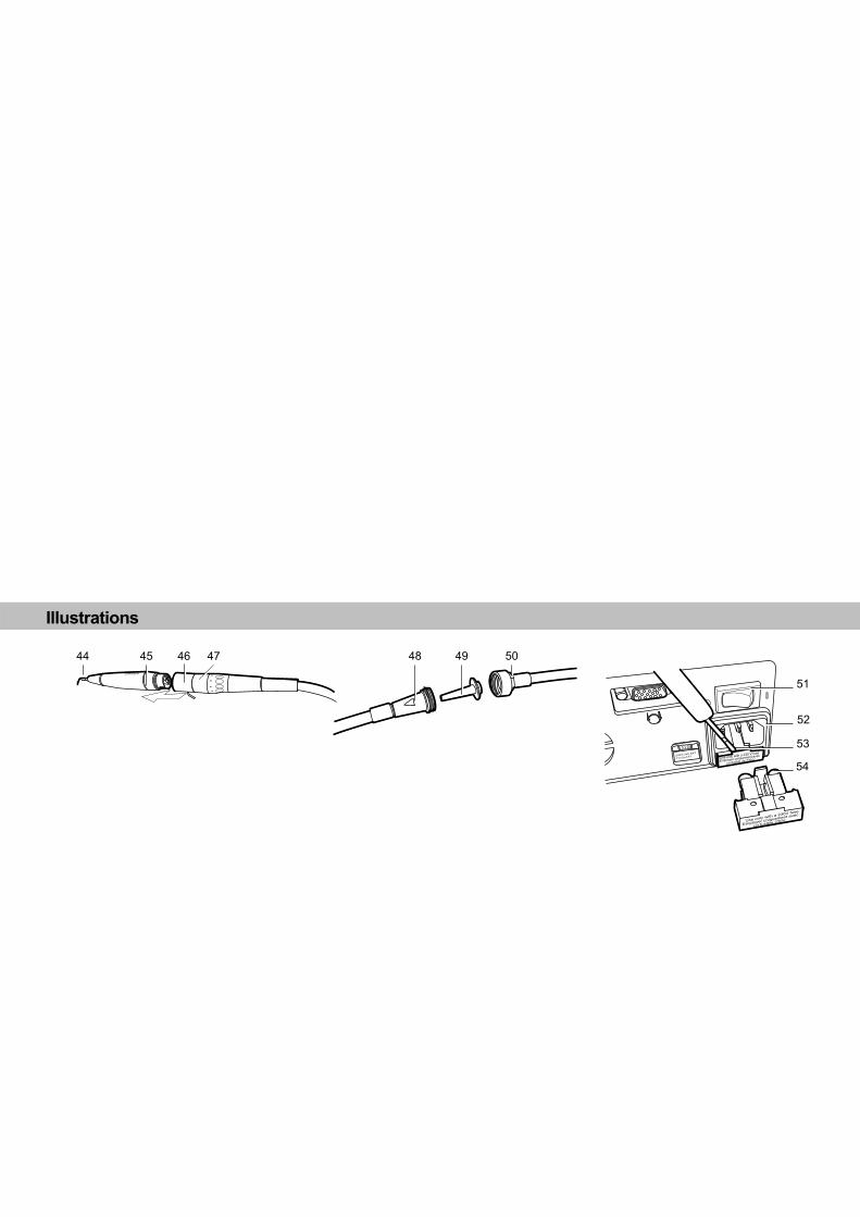
In the rear of the handpiece an irrigation circuit waterproof o’ring (1.15x1) is accessible and visible thanks to a groove of the rear socket. This allows for easy replacement of the o’ring in the case of damage or wearing. You can replace it yourself or have it done. After a number of disconnections/connections and/or sterilizations, it is recommended to lubricate this o’ring with dental instrument quality lubricant to maintain its efficiency and avoid internal leakage.
Without an irrigation kit Proceed as follows: 1. Separate the Suprasson® handpiece (ref .45)
from the cord (ref. 47) by pulling, without turning.
2. Unscrew the tip (ref. 44) from the Suprasson® handpiece.
3. Clean and sterilize the Suprasson® handpiece and tip after each use.
With an irrigation kit It is imperative that all parts in contact with the solution should be carefully rinsed after treating each patient as follows: 1. Disconnect the irrigation line from the kit. 2. Immerse it in clean water. 3. Press the pedal for one minute to rinse the
Sterijoint, the Suprasson® handpiece and the tip.
4. Disconnect the irrigation line from the Sterijoint, and discard.
5. Disconnect the Sterijoint unit (ref. 46), Suprasson® handpiece (ref. 47) and tip (ref. 44) from the cord.
6. Take out and empty the reservoirs. 7. Disinfect them. 8. Sterilize the reservoirs and the Sterijoint in an
autoclave. 9. Clean the motor and peristaltic pump with
alcohol every day.
Cleaning the filters
The water filter Cleaning the water filter must be done in relation to the hardness index of the water. 1. Shut off the water at the tap on the water
supply side and purge the circuit. 2. Set the on/off button to the "O" position and
unplug the mains lead. 3. Unscrew the two parts of the filter (ref. 48 and
50) using two 10mm open-ended spanners. 4. Extract and replace the cartridge (ref. 49). 5. Reassemble by reversing the operation,
retightening the two parts of the filter (ref. 48 and 50).
Air filter Refer to water filter section above.
Replacing the fuses Proceed as follows: 1. Set the on/off button to the "O" position (ref.
51) and unplug the mains lead (ref. 52). 2. Insert the end of a screwdriver (ref. 53) in the
slot to open the protective cover. 3. Replace the fuses (ref. 54) with fuses of the
same type and value. 4. Push the fuse holder back into its housing.
Fan 1. Check regularly that the fan is free from dust. 2. Clean if necessary by gentle blowing after
having disconnected the mains supply.
8
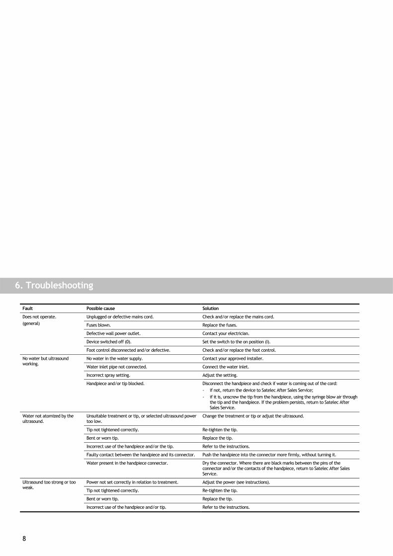
6. Troubleshooting
Fault Possible cause Solution
Unplugged or defective mains cord. Check and/or replace the mains cord.
Fuses blown. Replace the fuses.
Defective wall power outlet. Contact your electrician.
Device switched off (0). Set the switch to the on position (I).
Does not operate. (general)
Foot control disconnected and/or defective. Check and/or replace the foot control.
No water in the water supply. Contact your approved installer.
Water inlet pipe not connected. Connect the water inlet.
Incorrect spray setting. Adjust the setting.
No water but ultrasound working.
Handpiece and/or tip blocked. Disconnect the handpiece and check if water is coming out of the cord: - if not, return the device to Satelec After Sales Service; - if it is, unscrew the tip from the handpiece, using the syringe blow air through
the tip and the handpiece. If the problem persists, return to Satelec After Sales Service.
Unsuitable treatment or tip, or selected ultrasound power too low.
Change the treatment or tip or adjust the ultrasound.
Tip not tightened correctly. Re-tighten the tip.
Bent or worn tip. Replace the tip.
Incorrect use of the handpiece and/or the tip. Refer to the instructions.
Faulty contact between the handpiece and its connector. Push the handpiece into the connector more firmly, without turning it.
Water not atomized by the ultrasound.
Water present in the handpiece connector. Dry the connector. Where there are black marks between the pins of the connector and/or the contacts of the handpiece, return to Satelec After Sales Service.
Power not set correctly in relation to treatment. Adjust the power (see instructions).
Tip not tightened correctly. Re-tighten the tip.
Bent or worn tip. Replace the tip.
Ultrasound too strong or too weak.
Incorrect use of the handpiece and/or tip. Refer to the instructions.
9
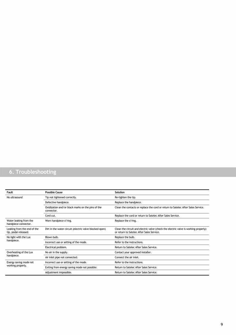
6. Troubleshooting
Fault Possible Cause Solution
Tip not tightened correctly. Re-tighten the tip.
Defective handpiece. Replace the handpiece.
Oxidization and/or black marks on the pins of the connector.
Clean the contacts or replace the cord or return to Satelec After Sales Service.
No ultrasound
Cord cut. Replace the cord or return to Satelec After Sales Service.
Water leaking from the handpiece connector.
Worn handpiece o’ring. Replace the o’ring.
Leaking from the end of the tip, pedal released.
Dirt in the water circuit (electric valve blocked open) Clean the circuit and electric valve (check the electric valve is working properly) or return to Satelec After Sales Service.
Blown bulb. Replace the bulb.
Incorrect use or setting of the mode. Refer to the instructions.
No light with the Lux handpiece.
Electrical problem. Return to Satelec After Sales Service.
No air in the supply. Contact your approved installer. Overheating of the Lux handpiece.
Air inlet pipe not connected. Connect the air inlet.
Incorrect use or setting of the mode. Refer to the instructions.
Exiting from energy saving mode not possible. Return to Satelec After Sales Service.
Energy saving mode not working properly.
Adjustment impossible. Return to Satelec After Sales Service.
10
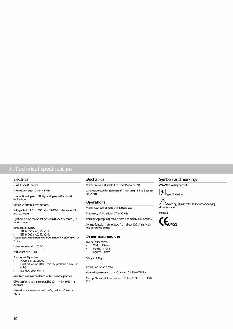
7. Technical specification
Electrical Class 1 type BF device
Intermittent duty 10 min / 5 min
Information display: LCD digital display with colored backlighting.
Option selection: press buttons.
Halogen bulb: 3.5 V / 750 mA / 15 000 lux (Suprasson® P Max Lux only)
Light out delay: can be set between 0 and 9 seconds (Lux version only)
Mains power supply • 110 to 150 V AC, 50/60 Hz • 230 to 260 V AC, 50/60 Hz Fuse protection: dimensions 5x20 mm, 0.5 A (230 V) or 1 A (115 V).
Power consumption: 55 VA
Insulation: 4kV (1 ms)
Factory configuration: • Power 5 in all ranges • Light out delay: after 3 mins (Suprasson® P Max Lux
only) • Standby: after 9 mins
Manufactured in accordance with current legislation
CEM: conforms to the general IEC 601-1 (= EN 60601-1) standard
Retention of the memorized configuration: 10 years at +25°C
Mechanical Water pressure at inlet: 1 to 5 bar (14 to 72 PSI)
Air pressure at inlet (Suprasson® P Max Lux): 4.5 to 6 bar (65 to 87 PSI)
Operational Water flow rate at exit: 0 to 120 ml/min
Frequency of vibrations: 27 to 33 kHz
Peristaltic pump: adjustable from 5 to 40 ml/min (optional)
Syringe function: rate of flow from about 120 l/min (with the peristaltic pump)
Dimensions and use Overall dimensions: • Width: 250mm • Height : 110mm • Depth: 300mm Weight: 2.7kg
Fixing: mount on a table
Operating temperature: +10 to +40 °C / 30 to 75% RH.
Storage/transport temperature: -40 to +70 °C / 10 to 100% RH
Symbols and markings Alternating current
Type BF device
Warning, please refer to the accompanying documentation.
Marking:
0459
I 597
00 -
N9 -
Vers
ion
2
17 av. Gustave Eiffel • BP 216 • 33708 MERIGNAC cedex • France • Tel. +33 (0) 556 34 06 07 • Fax. +33 (0) 556 34 92 92 E.mail : [email protected] • acteongroup.com
FRANCE Z.I. du Phare - B.P. 216 - F-33708 MERIGNAC CedexTel. ++33 (0) 556 34 06 07 - Fax. ++33 (0) 556 34 92 92 e-mail : [email protected]
U.S.A. 130 Gaither Drive, Suite 100, MOUNT LAUREL NJ 08034Tel. ++1 856 222 9988 - Fax. ++1 856 222 4726e-mail : [email protected]
GERMANY Industriestrasse 9 - D-40822 METTMANNTel. ++49 (0)21 04 / 95 65-10 - Fax. ++49 (0)21 04 / 95 65-11e-mail : [email protected]
SPAIN Av Principal - 11 H Poligono Indus - Can ClapersE-08181 SENTMENAT - BARCELONATel. ++34 93 715 33 66 - Fax. ++34 93 715 32 29 e-mail : [email protected]
U.K. Unit 1B - Steel Close - Little End Road - GB-EATON SOCON PE19 8TTTel. ++44 (0)1 480 477 307 - Fax. ++44 (0)1 480 477 381 e-mail : [email protected]
MIDDLE EAST Numan Center - 1st Floor N°111 - Gardens Street PO Box 468 - AMMAN 11953 - JORDANTel. ++962 6 553 4401 - Fax. ++962 6 553 7833 e-mail : [email protected]
CHINA Office 401 - 12 Xinyuanxili Zhong Street - Chaoyang District - BEIJING 100027Tel. ++86 10 646 570 11/2/3 - Fax. ++86 10 646 580 15 e-mail : [email protected]
PHILIPPINES 3F King's Court II Bldg. Pasong Tamo Street - Makati City - 1200 MANILATel. ++632 811 29 14-18 - Fax. ++632 811 24 88e-mail : [email protected]
KOREA 8F Hanil B/D - 132-4 1Ga Bongrae-dong Joong-gu - SEOULTel. ++82 2 753 41 91 - Fax. ++82 2 753 41 93 e-mail : [email protected]
INDIA E-91, G.I.D.C. Electronic Estate - Sector 26 - GANDHINAGAR-382044Tel. ++91 79 323 80 00 - Fax. ++91 79 642 58 51e-mail : [email protected]