supersonic retro propulsion fluid mechanics … conference...supersonic retro propulsion fluid...
TRANSCRIPT
Supersonic Retro PropulsionFluid MechanicsFundamentals
Lou CasselConsultant
08 May 2017
What’s Supersonic Retro-Propulsion (SRP)?
• SRP is rocket propulsion used to decelerate (or retard velocity) in supersonic, atmospheric flight
• There are two objectives of development of SRP for future applications
1. To retard spent launch vehicles velocity, facilitating turning back on their trajectory for recovery purposes (Most of this work is either classified or proprietary)
2. To retard velocity of Mars atmospheric entry vehicles that are too heavy for supersonic parachute technology (Much of this work is reported in open literature)
2
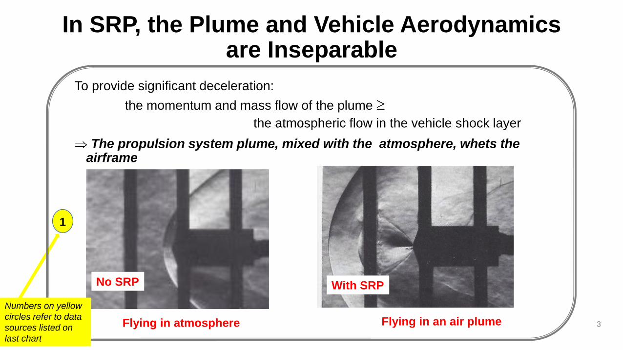
In SRP, the Plume and Vehicle Aerodynamics are Inseparable
To provide significant deceleration:
the momentum and mass flow of the plume
the atmospheric flow in the vehicle shock layer
The propulsion system plume, mixed with the atmosphere, whets the airframe
3
With SRPNo SRP
Flying in atmosphere Flying in an air plume
1
Numbers on yellow
circles refer to data
sources listed on
last chart
Why are the Fluid Mechanics ofSupersonic Retro-propulsion (SRP) Important?
• The aerodynamics interference (AI), by rocket motor plumes exhausting “into the wind”, introduces an uncertain flight environment for the airframe
• The SRP AI coupling of aerodynamics and propulsion influences selection, and design of, attitude stability and control concepts
• Propulsion system performance parameters influence aerodynamics
• Mitigation of aerodynamics interference adds design requirements for the propulsion system
4
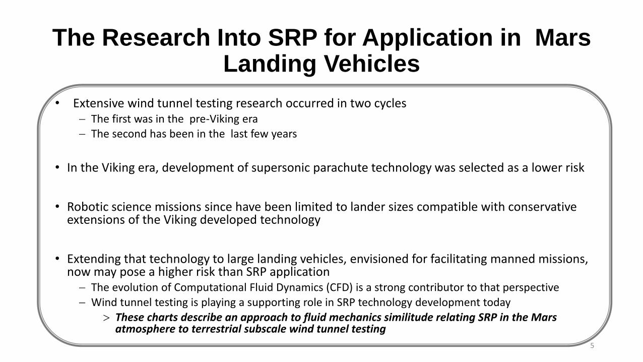
The Research Into SRP for Application in MarsLanding Vehicles
• Extensive wind tunnel testing research occurred in two cycles The first was in the pre-Viking era The second has been in the last few years
• In the Viking era, development of supersonic parachute technology was selected as a lower risk
• Robotic science missions since have been limited to lander sizes compatible with conservative extensions of the Viking developed technology
• Extending that technology to large landing vehicles, envisioned for facilitating manned missions, now may pose a higher risk than SRP application The evolution of Computational Fluid Dynamics (CFD) is a strong contributor to that perspective Wind tunnel testing is playing a supporting role in SRP technology development today
These charts describe an approach to fluid mechanics similitude relating SRP in the Mars atmosphere to terrestrial subscale wind tunnel testing
5
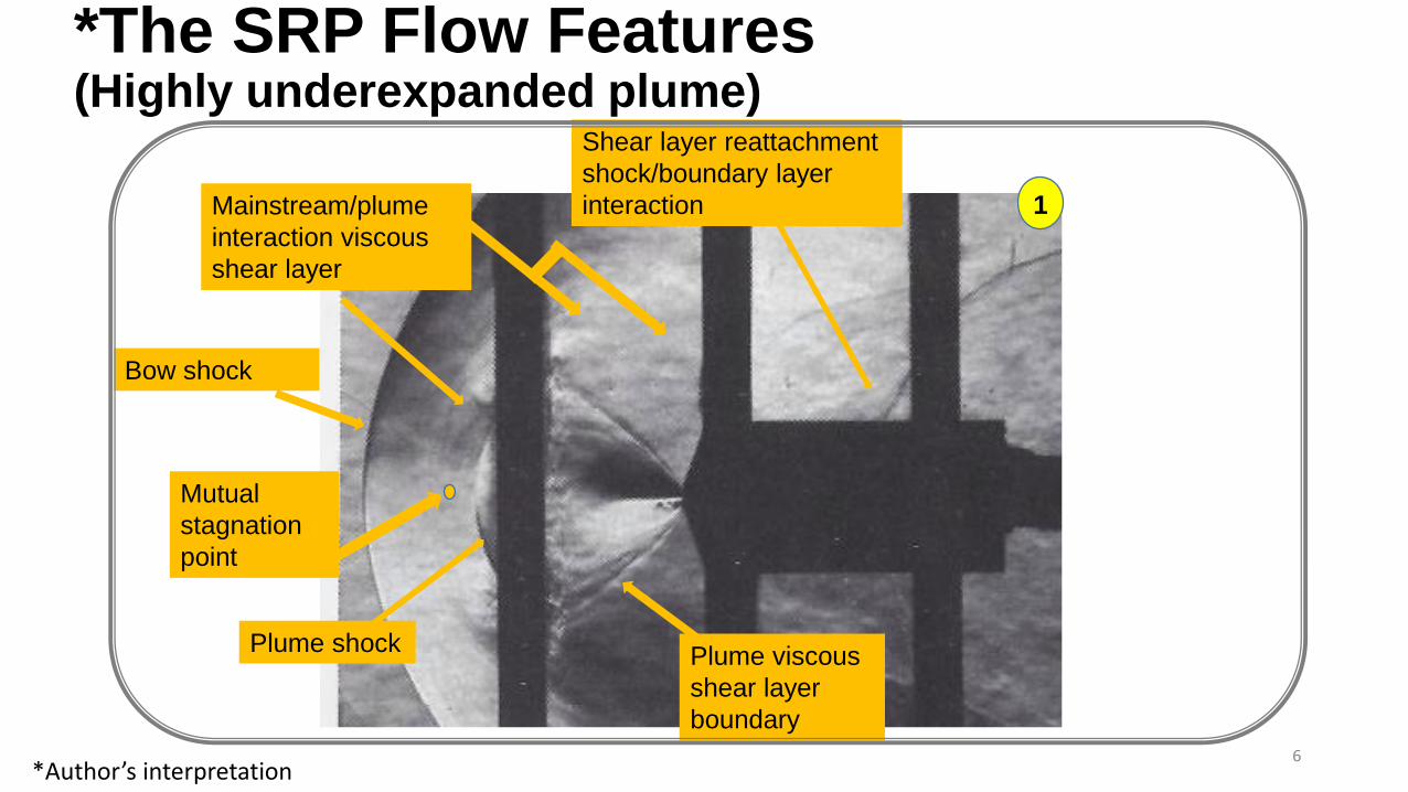
*The SRP Flow Features (Highly underexpanded plume)
6
Plume shockPlume viscous
shear layer
boundary
Mainstream/plume
interaction viscous
shear layer
Shear layer reattachment
shock/boundary layer
interaction
Bow shock
Mutual
stagnation
point
1
*Author’s interpretation
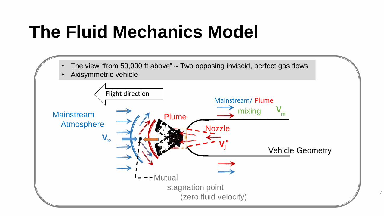
The Fluid Mechanics Model
7
Vj*
Vm
V
Mainstream
AtmospherePlume
Nozzle
Vehicle Geometry
mixing
PlumeMainstream/
Mutual
stagnation point
(zero fluid velocity)
Flight direction
• The view “from 50,000 ft above” Two opposing inviscid, perfect gas flows
• Axisymmetric vehicle
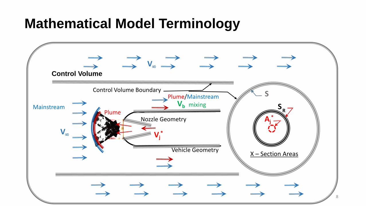
Mathematical Model Terminology
8
Control Volume
Aj*
SR
S
Vj*
Vb
V
MainstreamPlume
Plume/Mainstreammixing
Nozzle Geometry
Vehicle Geometry
Control Volume Boundary
V
X – Section Areas
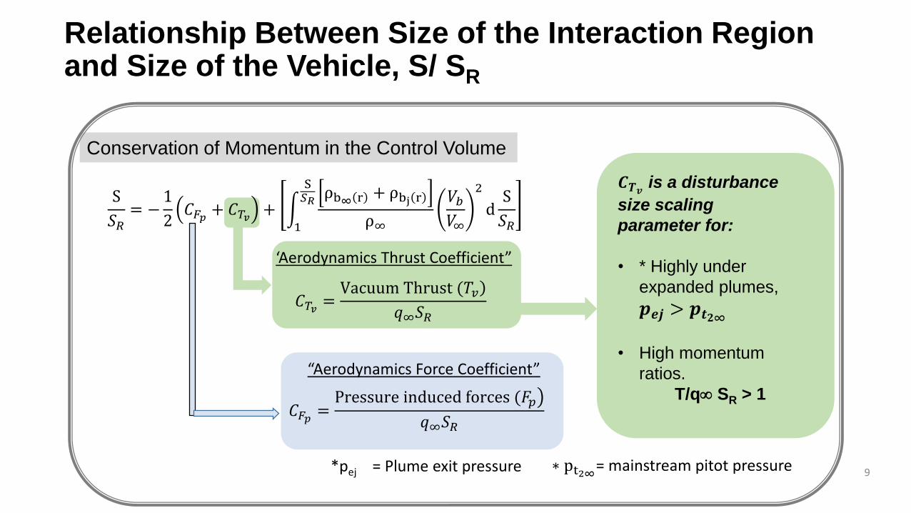
Relationship Between Size of the Interaction Region and Size of the Vehicle, S/ SR
9
𝐶𝑇𝑣 = Vacuum Thrust (𝑇𝑣
𝑞∞𝑆𝑅
Conservation of Momentum in the Control Volume
𝑪𝑻𝒗is a disturbance
size scaling
parameter for:
• * Highly under
expanded plumes,
𝒑𝒆𝒋 > 𝒑𝒕𝟐∞
• High momentum
ratios.
T/q SR > 1
∗ pt2∞= mainstream pitot pressure
‘Aerodynamics Thrust Coefficient”
S
𝑆𝑅= −
1
2𝐶𝐹𝑝 + 𝐶𝑇𝑣 +
1
S𝑆𝑅
ρb∞ r + ρbj r
ρ∞
𝑉𝑏
𝑉∞
2
dS
𝑆𝑅
𝐶𝐹𝑝 = Pressure induced forces (𝐹𝑝
𝑞∞𝑆𝑅
*pej = Plume exit pressure
“Aerodynamics Force Coefficient”
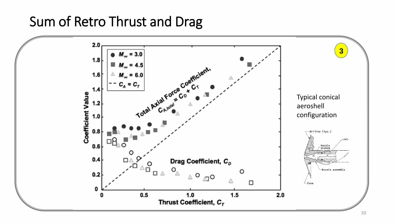
Sum of Retro Thrust and Drag
10
3
Typical conical aeroshellconfiguration
-
0.20
0.40
0.60
0.80
1.00
1.20
1.40
- 0.50 1.00 1.50
Bo
w S
ho
ck H
eig
ht/
Bas
e D
iam
ete
r
SQRT Aero Thrust Coeff (T/qS)*0.5
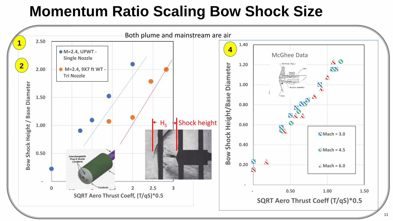
McGhee Data
Mach = 3.0
Mach = 4.5
Mach = 6.0
Momentum Ratio Scaling Bow Shock Size
4
-
0.50
1.00
1.50
2.00
2.50
0 0.5 1 1.5 2 2.5 3
Bo
w S
ho
ck H
eig
ht
/ B
ase
Dia
met
er
SQRT Aero Thrust Coeff, (T/qS)*0.5
M=2.4, UPWT -Single Nozzle
M=2.4, 9X7 ft WT -Tri Nozzle
2
1
HS Shock height
Both plume and mainstream are air
11
-0.16
-0.14
-0.12
-0.10
-0.08
-0.06
-0.04
-0.02
0.00
0 1 2 3 4 5 6 7 8 9 10
Pre
ssu
re C
oef
f, C
p
x (in)
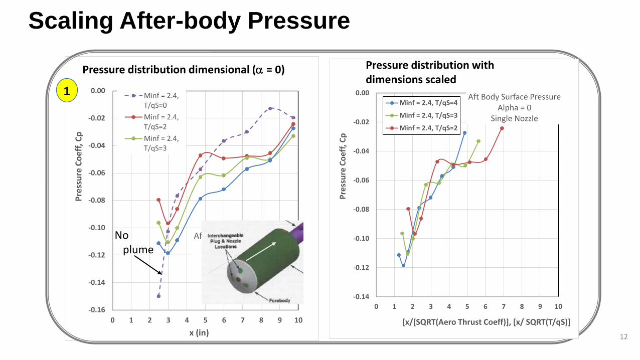
Aft Body Surface Pressure Alpha = 0
Single Nozzle
Minf = 2.4,T/qS=0
Minf = 2.4,T/qS=2
Minf = 2.4,T/qS=3
Scaling After-body Pressure
12
No plume
Pressure distribution dimensional ( = 0) Distribution scaled with momentum ratio
1
-0.14
-0.12
-0.10
-0.08
-0.06
-0.04
-0.02
0.00
0 1 2 3 4 5 6 7 8 9 10
Pre
ssu
re C
oef
f, C
p
[x/[SQRT(Aero Thrust Coeff)], [x/ SQRT(T/qS)]
Aft Body Surface Pressure Alpha = 0
Single Nozzle
Minf = 2.4, T/qS=4
Minf = 2.4, T/qS=3
Minf = 2.4, T/qS=2
Pressure distribution with dimensions scaled
Scaling Atmosphere and Plume Gasses
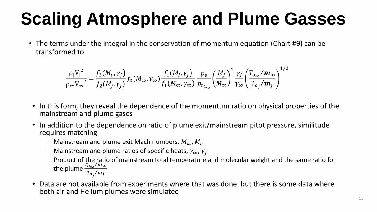
• The terms under the integral in the conservation of momentum equation (Chart #9) can be transformed to
13
ρjVj2
ρ∞V∞2 =
𝑓2(𝑀𝑒 , 𝛾𝑗
𝑓2(𝑀𝑗 , 𝛾𝑗𝑓3(𝑀∞, 𝛾∞
𝑓1(𝑀𝑗 , 𝛾𝑗 𝑓1(𝑀∞, 𝛾∞
𝑝𝑒
𝑝𝑡2∞
𝑀𝑗
𝑀∞
2𝛾𝑗
𝛾∞
𝑇𝑜∞𝒎∞
𝑇𝑜𝑗𝒎𝑗
1 2
• In this form, they reveal the dependence of the momentum ratio on physical properties of the mainstream and plume gases
• In addition to the dependence on ratio of plume exit/mainstream pitot pressure, similitude requires matching Mainstream and plume exit Mach numbers, 𝑀∞, 𝑀𝑒
Mainstream and plume ratios of specific heats, 𝛾∞, 𝛾𝑗 Product of the ratio of mainstream total temperature and molecular weight and the same ratio for
the plume 𝑇𝑜∞ 𝒎∞
𝑇𝑜𝑗𝒎𝑗
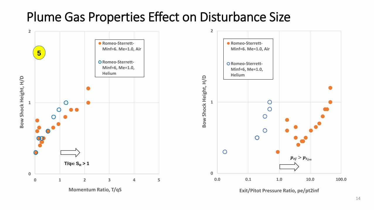
• Data are not available from experiments where that was done, but there is some data where both air and Helium plumes were simulated
0
1
2
0.0 0.1 1.0 10.0 100.0
Bo
w S
ho
ck H
eig
ht,
H/D
Exit/Pitot Pressure Ratio, pe/pt2inf
Romeo-Sterrett-Minf=6. Me=1.0, Air
Romeo-Sterrett-Minf=6, Me=1.0,Helium
Plume Gas Properties Effect on Disturbance Size
14
0
1
2
0 1 2 3 4 5
Bo
w S
ho
ck H
eig
ht,
H/D
Momentum Ratio, T/qS
Romeo-Sterrett-Minf=6. Me=1.0, Air
Romeo-Sterrett-Minf=6, Me=1.0,Helium
𝒑𝒆𝒋 > 𝒑𝒕𝟐∞
T/q SR > 1
5
Other Influencing Phenomena
• Only symmetric, supersonic flight conditions have been addressed Transonic and subsonic flight significantly change the plume interference physics
• Only highly under-expanded plumes, at thrust levels commensurate with significant deceleration, have been analyzed here
• There are two other modes of supersonic retro-plume interference (not addressed here) In one of these the shock layer configuration, and associated pressures, fluctuate at kHz frequencies In the other, termed long plume mode (LPM), the strong shock transforms to an elongated (slender body like)
shock Experimental results indicate a hysteresis in changes from one mode to the other when the nozzle chamber
pressure is throttled up and down.
• Both of these other modes appear (to this author) to be associated with either: Lower nozzle exit/ mainstream pitot pressure ratios Thrust levels too low to cause significant deceleration (lower T/qS)
15
Summary
• Scaling of large scale features of the aerodynamic interference due to supersonic retro-propulsion has been reviewed
• These first order features have been shown (at least in some data) to scale with the momentum ratios of the propulsion and aerodynamic streams
• The correlations described pertain to interference flows meeting two conditions
Highly under expanded plumes, 𝑝𝑒𝑗 > 𝑝𝑡2∞
High momentum ratios: T/qS > 1
• Outside of those conditions, there are modes of the interference phenomena that behave quite differently
16
Data Sources
1. Berry, Scott A., Rhode, Matthew N., and Enquist, Supersonic Retropropulsion Experimental Results From NASA Ames 9X7 Foot Supersonic Wind Tunnel. J.S.R. June 2014 (Reproduced)
2. Berry, Scott A., Rhode, Matthew N., and Enquist, Supersonic Retropropulsion Validation Experiment in the NASA Langley Unitary Plan Wind Tunnel. J.S.R. June 2014 (Reproduced)
3. Korzun, Ashley M., Robert D. Braun, Juan R, Cruz. Survey of Supersonic Retropropulsion Technology for Mars Entry, Descent, and Landing. J. of Spacecraft and Rockets Sept-Oct 2009
4. McGhee, Robert J., Effects of a Retro Nozzle Located at the Apex of a 140° Blunt Cone at Mach Numbers of 3.00, 4.50, and 6.00. NASA Technical Note D-6002, January 1971
5. Romeo, David J., and J.R. Sterrett. Exploratory Investigation of the Effect of a Forward-Facing Jet on the Bow Shock of a Blunt Body in a Mach Number 6 Free Stream, NASA TN D-1605
17