superior corrosion protection effectiveness of vpci … of corrosion... · superior corrosion...
TRANSCRIPT
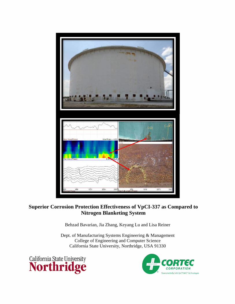
Superior Corrosion Protection Effectiveness of VpCI-337 as Compared to Nitrogen Blanketing System
Behzad Bavarian, Jia Zhang, Keyang Lu and Lisa Reiner
Dept. of Manufacturing Systems Engineering & Management
College of Engineering and Computer Science California State University, Northridge, USA 91330
Executive Summary Corrosion behavior of steel samples used for storage tanks and cross casing pipe applications were investigated using two different protection mechanisms: vapor corrosion inhibitor and nitrogen blanketing system. The objective of this project was to demonstrate which technique provides more protection in corrosive environments, especially where there are restricted geometries such as crevices, threads, notches and under-deposits. The corrosion behavior of steel samples (probes) was studied in two different conditions. Two probes were placed in an environment that contained 200 ppm chloride solution + 10% corrosion inhibitor. Two additional steel probes were placed in a different environment that included 200 ppm chloride solution (no inhibitor) and a nitrogen blanketing system at 10 psi applied pressure. In each case, one probe was immersed in solution and the other was suspended above the solution. The corrosion rate of the steel samples was monitored for more than five months (~4,000 hours) using linear polarization resistance (LPR) and electrical resistance (ER) probe techniques. The corrosion data have demonstrated that vapor phase corrosion inhibitors have superior advantages over nitrogen blanketing system in the presence of excessive salt and moisture. On average, the LPR corrosion rate measured less than 0.06 mpy for samples immersed in and exposed to the VpCI solution with no signs of corrosion. The immersed and nitrogen blanketed samples, in contrast, showed a corrosion rate of 1.78 mpy and were covered with a thick red rust. The ER probes showed a corrosion rate of 0.18 mpy for the VpCI treated samples, while the nitrogen blanketed samples showed a 2.12 mpy corrosion rate and the probes were heavily corroded. It is interesting to report that when VpCI was injected into the nitrogen blanketed corrosion cell, the corrosion rate of the corroded steel probes dropped to less than 0.26 mpy in less than 20 hours, and eventually to less than 0.04 mpy after 72 hours. This shows a significant reduction in the corrosion rate by more than eight times. Despite the fact that nitrogen blanket protection system in theory can suppress the cathodic reaction and lower the corrosion rate, in reality the amount of moisture and oxygen that is required to initiate the corrosion reaction for steel is extremely low. Therefore, the nitrogen blanket system can reduce the moisture level, but it won’t be enough to prevent corrosion and the steel sample will corrode eventually. The advantage of the VpCI inhibitor is the creation of a strong physisorption to the steel surface that minimizes any surface contact with corrosive species. This surface interaction would result in excellent long term corrosion protection. Therefore, vapor phase corrosion inhibitors have superior advantages over the nitrogen blanketing system in the presence of excessive salt, oxygen and moisture.
Introduction Steel storage tanks, both above ground and below, are abundant throughout the world given their use in multiple industries such as power generation, municipal water, biodiesel, mining, waste, oil and gas. Their prevalence is not surprising considering the variety of storage tank contents: grain, water, oil, chemicals, and fuel. Storage tanks, however, are susceptible to corrosion when exposed to moisture or an aggressive environment. The atmosphere on earth contains moisture, and when water is present as well as oxygen, the combination can cause metals (structures, parts, equipment, tanks and pipes) to corrode, sometimes with catastrophic consequences. In the absence of oxygen, water is still corrosive but at a much slower rate. The costs associated with corrosion go far beyond the 350 billion US dollars estimated for the year 2000 [1] in financial considerations and include plant shutdowns, leaking containers, loss of products and employment, contamination, and hazards to human and wildlife. Classical methods of protecting equipment from atmospheric attack include the use of coatings or paints and alloying the metal to increase its resistance to corrosion. Other commonly used mitigation techniques include sparging, inerting and blanketing. A technique referred to as tank blanketing applies a gas cover to prevent combustion and degradation. Gas blankets have been used on storage tanks downstream of other deoxygenation devices, such as vacuum degasifiers and oxygen stripping columns, to preserve deoxygenated water. Nitrogen gas blankets have been used on utility boilers during downtime corrosion control. The mechanism for this type of corrosion attack is electrochemical in nature; its electrolyte derives from a thin layer of humidity on the surface of the metal [2]. An alternative protection method that is both effective in controlling vapor phase corrosion and inexpensive, uses vapor phase corrosion inhibitors (VpCI). A vapor phase corrosion inhibitor is a volatile compound and must be capable of forming a stable bond at the interface of the metal, preventing penetration of corrosive species [3-8].VpCIs offer an alternative way to protect storage tanks and their contents, cross casing pipes, or metallic structures in general. These inhibitors are easy to apply, versatile and can be used to protect multiple metal types in a variety of industries. Casings, mentioned previously, are commonly used to surround and protect pipelines where the lines cross highways, railroads and similar locations. If isolation is impractical, other measures must be taken to minimize corrosion of the pipeline inside the casing. The vapor phase corrosion inhibitors are well suited for this application and for protection of internal void spaces and exposed surfaces [9-15].These materials have stable passivating properties, strong tendencies toward surface adsorption, and the ability to form a comparatively strong and stable bond with the metal surface [7-21]. Compared to other methods of corrosion prevention such as nitrogen blanketing and dehumidification, vapor phase corrosion inhibitors (VpCI) provide substantially better corrosion control at lower cost and require very low dosage rate. For practical purposes, it is preferable to use less volatile inhibitors that provide long-lasting and durable protection over periods of 2 to 3 years. Components and equipment treated with VpCI will have indoor protection up to 24 months without reapplication and roughly 6 months for outdoor protection [3-4]. The protection is independent of environmental conditions and is effective even in extreme conditions. Previous research on ASTM A470 steel confirms the benefits of using this technology in gas and steam turbines that are susceptible to stress corrosion cracking and crevice corrosion [22]. In this study,
the addition of VpCI increased the resistance polarization (Rp) values during electrochemical impedance testing as compared to ASTM A470 steel samples tested without inhibitor. The higher Rp values were attributed to the progressive adsorption of inhibitor molecules and film formation on the metal surface [22]. The corrosion inhibition mechanism was determined to be the physical adsorption of inhibitor molecules to the metal surfaces [23]. Physical adsorption requires energy between -5 to -20 kJ/mol [24]. The analysis of the inhibitor showed an enthalpy of adsorption in the range of -14 to-18 kJ/mol [23]. Generally, chemisorption requires more energy and results in stronger bonding between the molecules and the surface of the substrate, ergo, a more stable protective film [25]. The majority of corrosion damage to turbo-machinery systems, however, occurs during the shutdown period due to chemistry changes and stagnant condition in localized areas. Therefore, a corrosion inhibitor with strong physical adsorption to the metal surface will provide satisfactory protection and does not require strong chemical bonding. The vapor phase corrosion inhibitors are water-based and ideal for equipment with complex geometries such as boilers, heat recovery steam generators and pressure vessels. VpCI forms a solution in water and when applied by spraying or dipping, will protect ferrous and nonferrous metals, including castings, tubular parts, finished parts, gears, pumps, housings, structural steel, sintered metals, bars and roll stock. VpCI has excellent wetting properties and forms a clear, dry, hydrophobic film of roughly 0.25 mils thick (6.35 micron) on the surface that is stable up to 350°F (176°C) [3]. Adsorption of the inhibitor on to the metal surface provides a protective inhibitor layer. As well, the vapor phase action protects surfaces that have not been directly coated and are difficult to reach. This type of corrosion inhibitor is useful when oil, grease or other adherent films are not practical. The inhibitor is transmitted by vapor and the vapor phase is controlled by the crystal lattice structure and the atomic bond characteristics of the molecule [2]. The protective vapor expands within the enclosed space until the equilibrium determined by its partial pressure is reached; the higher the vapor pressure, the sooner the saturation of protected space. The VpCI organic chemistry is free of hazardous amines, nitrites and phosphate ester. There are no hazardous decomposition by-products. Furthermore, the product is biodegradable and non-flammable unlike some of the earlier chemicals tested in the 1940s and 1950s: dicyclohexyl ammonium nitrite, ammonium nitrite (NH4NO3), urea (CO [NH2]2), and acetamide (CH3CONH2) [2]. A commonly used corrosion mitigation technique is tank blanketing, or tank padding. This process applied an inert, relatively inexpensive gas to the empty space in a storage container. Though tank blanketing is used for a variety of reasons, it typically involves an inert buffer gas to protect the storage container and its contents. The buffer gas adds pressure to a system and controls the speed of combustion with existing oxygen. A few of the benefits of blanketing include a longer product life, reduced hazards, and longer equipment life cycles. When storing highly volatile substances or substances likely to oxidize, safety and product preservation are important goals. The list of products blanketed is extensive and includes adhesives, catalyst, chemicals, fats and oils, foods, fuels, inks, pharmaceuticals, photographic chemicals, soaps, and water. Nitrogen is used in a wide range of industries to either prevent degradation of food, chemicals and metallic vessels due to atmospheric oxidation and corrosion, or to enhance safety by
preventing the possibility of combustion, for instance when solvents are being stored. This is a safe and reliable way to protect food from degrading as a result of oxidation. Oxidation is a chemical reaction where atmospheric oxygen attacks the food surface or metal. The presence of nitrogen keeps oxygen levels in and around the product low. Humid air in the head space is replaced by high purity, inert, dry nitrogen. Nitrogen is an inert gas that does not support the corrosion reaction. Nitrogen effectively displaces all oxygen from the system and stops the corrosion reaction by eliminating the cathodic oxygen reaction. The dew point of 95% nitrogen is approximately -40°F, which enables it to absorb significantly more moisture than compressed air. From a corrosion point of view, air is roughly 20% oxygen, 80% nitrogen. Since fuels require oxygen to combust, reduced oxygen content in the vapor space lowers the risk of unwanted combustion. A precise valve control system ensures that as the tank is filled or emptied, the nitrogen content is automatically compensated to maintain the protective blanket. To effectively perform any of these functions the blanketing system must be capable of pressurizing the vapor space and accurately maintaining that pressure. There are various ways to achieve a blanket. One method involves continuous purging, whereby blanketing gas introduced into the tank as a continuous flow exits through a vent or other opening. This method requires more gas and is not always effective in maintaining an inert atmosphere. Another approach uses a simple, direct-operated pressure-reducing valve (PRV) to blanket the tank. However, these devices are best suited for a continuous flow rate. When used to blanket a tank they must throttle over a wide flow range. Ranging from a shut-off to a full flow condition varies the controlled pressure significantly due to droop and lockup conditions. Pressure variations can be as much as 30 percent below or 20 percent above the setpoint. This results in poor control, wasting of blanketing gas, and possibly not maintaining the necessary atmosphere within the tank. Nitrogen blanketing has been successfully used in many industries for protection of plant equipment, but it requires constant maintenance of the gas levels and additional equipment with a valve system for control. Advances have been made in corrosion science technology, given the ease of application, the versatility of the product, its bio-friendliness, and above all, its effective performance; it might be time to apply some VpCI. Experimental Procedure Corrosion inhibition of Inhibitor-VpCI 337 was determined for 1020 carbon steel commonly used in tank and casing applications. Electrochemical polarization standards per ASTM-G61were used to evaluate the behavior of this inhibitor on the steel alloy in 200 ppm chloride solution using linear polarization resistance (LPR) and electrical resistance (ER) techniques and to compare with nitrogen gas blanketing. These techniques can provide useful information regarding the corrosion mechanisms, corrosion rate and localized corrosion susceptibility of a material in a given environment. CORRATER® systems operate on the fundamental principle that a metal corroding through oxidation will generate a small electrical current. A CORRATER® instrument determines the corrosion rate by measuring the current from a small applied potential difference between the two electrodes. CORRATER® systems measure the instantaneous corrosion rate of a metal in a conductive fluid using the linear polarization resistance measurement technique. Automatic
solution resistance compensation improves the utility, convenience and accuracy of corrosion rate measurements. The 9030 Plus also monitors a form of Electrochemical Current Noise (ECN) between the electrodes called imbalance (or pitting tendency). This is a qualitative and very useful indication of instability in the material surface consistent with pitting or localized corrosion [26].The major advantage to LPR monitoring is the speed in which it can provide a measurement of the corrosion rate. Changes in the corrosion rate can typically be detected in minutes, providing an almost instantaneous measuring system. This fast response allows an operator to evaluate process changes and is particularly useful in monitoring the effectiveness of prevention program. LPR monitoring can also give an indication of metal behavior, for example when an alloy changes from a passive to an active state, thereby resulting in increased susceptibility to corrosion
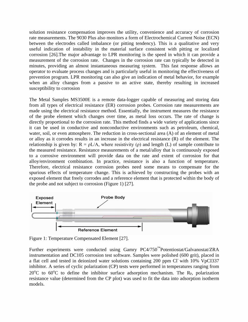
The Metal Samples MS3500E is a remote data-logger capable of measuring and storing data from all types of electrical resistance (ER) corrosion probes. Corrosion rate measurements are made using the electrical resistance method. Essentially, the instrument measures the resistance of the probe element which changes over time, as metal loss occurs. The rate of change is directly proportional to the corrosion rate. This method finds a wide variety of applications since it can be used in conductive and nonconductive environments such as petroleum, chemical, water, soil, or even atmosphere. The reduction in cross-sectional area (A) of an element of metal or alloy as it corrodes results in an increase in the electrical resistance (R) of the element. The relationship is given by: R = ρL/A, where resistivity (ρ) and length (L) of sample contribute to the measured resistance. Resistance measurements of a metal/alloy that is continuously exposed to a corrosive environment will provide data on the rate and extent of corrosion for that alloy/environment combination. In practice, resistance is also a function of temperature. Therefore, electrical resistance corrosion probes need some means to compensate for the spurious effects of temperature change. This is achieved by constructing the probes with an exposed element that freely corrodes and a reference element that is protected within the body of the probe and not subject to corrosion (Figure 1) [27].
Figure 1: Temperature Compensated Element [27]. Further experiments were conducted using Gamry PC4/750™Potentiostat/Galvanostat/ZRA instrumentation and DC105 corrosion test software. Samples were polished (600 grit), placed in a flat cell and tested in deionized water solutions containing 200 ppm Cl- with 10% VpCI337 inhibitor. A series of cyclic polarization (CP) tests were performed in temperatures ranging from 20oC to 60oC to define the inhibitor surface adsorption mechanism. The Rp, polarization resistance value (determined from the CP plot) was used to fit the data into adsorption isotherm models.
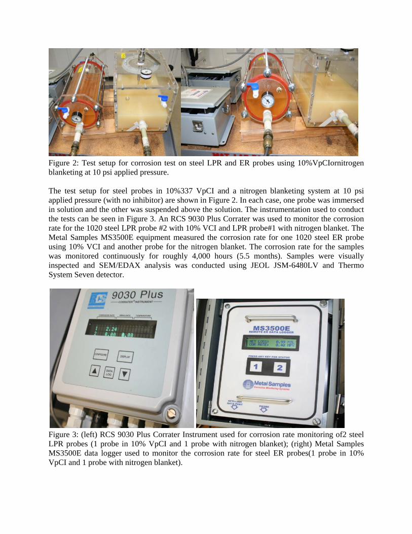
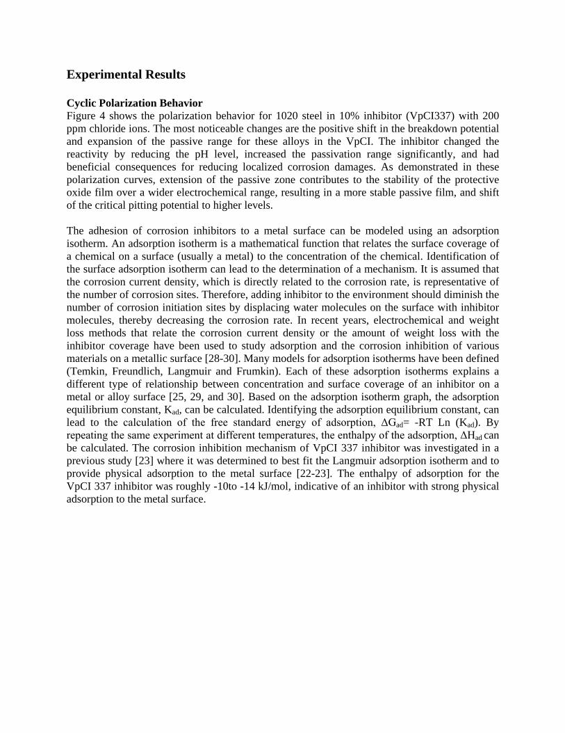
Figure 2: Test setup for corrosion test on steel LPR and ER probes using 10%VpCIornitrogen blanketing at 10 psi applied pressure. The test setup for steel probes in 10%337 VpCI and a nitrogen blanketing system at 10 psi applied pressure (with no inhibitor) are shown in Figure 2. In each case, one probe was immersed in solution and the other was suspended above the solution. The instrumentation used to conduct the tests can be seen in Figure 3. An RCS 9030 Plus Corrater was used to monitor the corrosion rate for the 1020 steel LPR probe #2 with 10% VCI and LPR probe#1 with nitrogen blanket. The Metal Samples MS3500E equipment measured the corrosion rate for one 1020 steel ER probe using 10% VCI and another probe for the nitrogen blanket. The corrosion rate for the samples was monitored continuously for roughly 4,000 hours (5.5 months). Samples were visually inspected and SEM/EDAX analysis was conducted using JEOL JSM-6480LV and Thermo System Seven detector.
Figure 3: (left) RCS 9030 Plus Corrater Instrument used for corrosion rate monitoring of2 steel LPR probes (1 probe in 10% VpCI and 1 probe with nitrogen blanket); (right) Metal Samples MS3500E data logger used to monitor the corrosion rate for steel ER probes(1 probe in 10% VpCI and 1 probe with nitrogen blanket).
Experimental Results Cyclic Polarization Behavior Figure 4 shows the polarization behavior for 1020 steel in 10% inhibitor (VpCI337) with 200 ppm chloride ions. The most noticeable changes are the positive shift in the breakdown potential and expansion of the passive range for these alloys in the VpCI. The inhibitor changed the reactivity by reducing the pH level, increased the passivation range significantly, and had beneficial consequences for reducing localized corrosion damages. As demonstrated in these polarization curves, extension of the passive zone contributes to the stability of the protective oxide film over a wider electrochemical range, resulting in a more stable passive film, and shift of the critical pitting potential to higher levels. The adhesion of corrosion inhibitors to a metal surface can be modeled using an adsorption isotherm. An adsorption isotherm is a mathematical function that relates the surface coverage of a chemical on a surface (usually a metal) to the concentration of the chemical. Identification of the surface adsorption isotherm can lead to the determination of a mechanism. It is assumed that the corrosion current density, which is directly related to the corrosion rate, is representative of the number of corrosion sites. Therefore, adding inhibitor to the environment should diminish the number of corrosion initiation sites by displacing water molecules on the surface with inhibitor molecules, thereby decreasing the corrosion rate. In recent years, electrochemical and weight loss methods that relate the corrosion current density or the amount of weight loss with the inhibitor coverage have been used to study adsorption and the corrosion inhibition of various materials on a metallic surface [28-30]. Many models for adsorption isotherms have been defined (Temkin, Freundlich, Langmuir and Frumkin). Each of these adsorption isotherms explains a different type of relationship between concentration and surface coverage of an inhibitor on a metal or alloy surface [25, 29, and 30]. Based on the adsorption isotherm graph, the adsorption equilibrium constant, Kad, can be calculated. Identifying the adsorption equilibrium constant, can lead to the calculation of the free standard energy of adsorption, ΔGad= -RT Ln (Kad). By repeating the same experiment at different temperatures, the enthalpy of the adsorption, ΔHad can be calculated. The corrosion inhibition mechanism of VpCI 337 inhibitor was investigated in a previous study [23] where it was determined to best fit the Langmuir adsorption isotherm and to provide physical adsorption to the metal surface [22-23]. The enthalpy of adsorption for the VpCI 337 inhibitor was roughly -10to -14 kJ/mol, indicative of an inhibitor with strong physical adsorption to the metal surface.
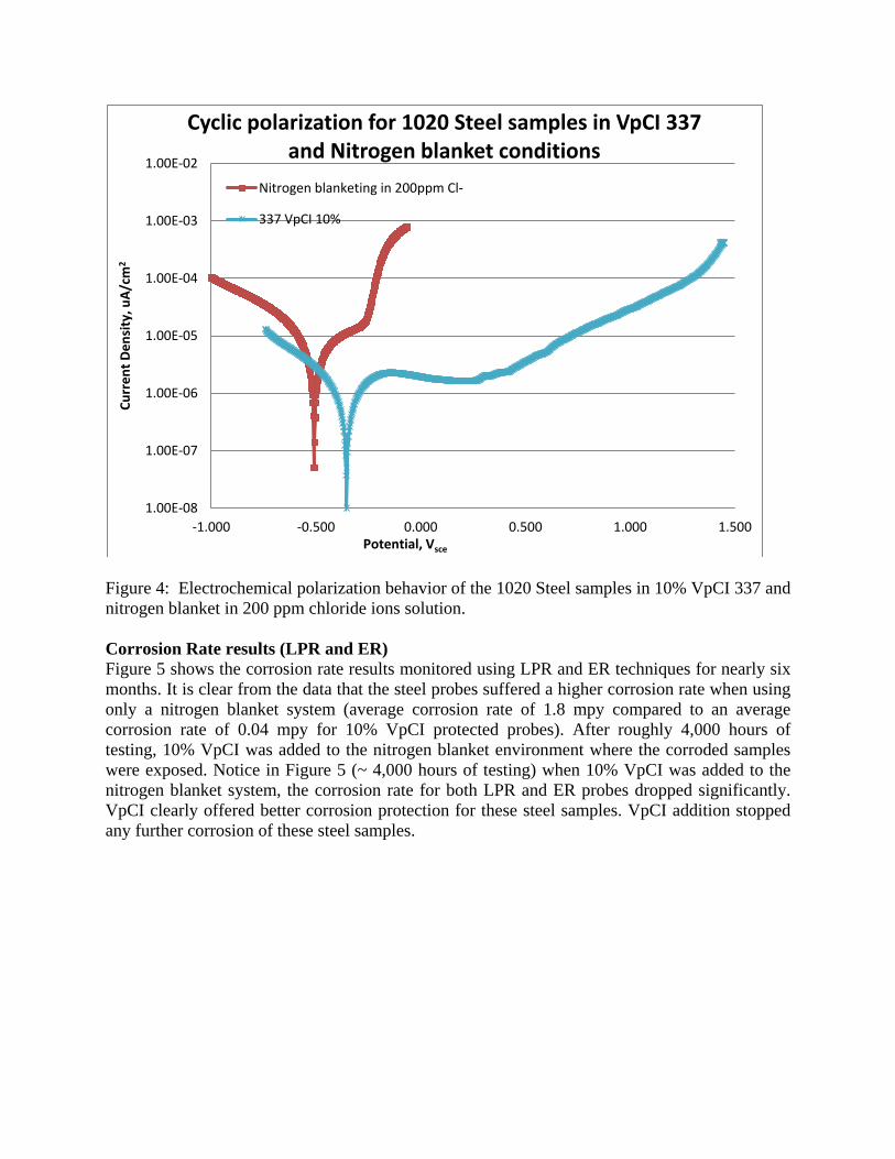
Figure 4: Electrochemical polarization behavior of the 1020 Steel samples in 10% VpCI 337 and nitrogen blanket in 200 ppm chloride ions solution. Corrosion Rate results (LPR and ER) Figure 5 shows the corrosion rate results monitored using LPR and ER techniques for nearly six months. It is clear from the data that the steel probes suffered a higher corrosion rate when using only a nitrogen blanket system (average corrosion rate of 1.8 mpy compared to an average corrosion rate of 0.04 mpy for 10% VpCI protected probes). After roughly 4,000 hours of testing, 10% VpCI was added to the nitrogen blanket environment where the corroded samples were exposed. Notice in Figure 5 (~ 4,000 hours of testing) when 10% VpCI was added to the nitrogen blanket system, the corrosion rate for both LPR and ER probes dropped significantly. VpCI clearly offered better corrosion protection for these steel samples. VpCI addition stopped any further corrosion of these steel samples.
1.00E-08
1.00E-07
1.00E-06
1.00E-05
1.00E-04
1.00E-03
1.00E-02
-1.000 -0.500 0.000 0.500 1.000 1.500
Curr
ent D
ensi
ty, u
A/cm
2
Potential, Vsce
Cyclic polarization for 1020 Steel samples in VpCI 337 and Nitrogen blanket conditions
Nitrogen blanketing in 200ppm Cl-
337 VpCI 10%
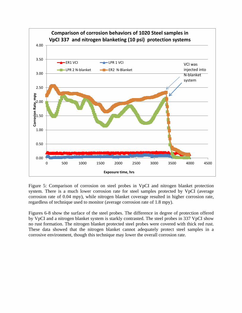
Figure 5: Comparison of corrosion on steel probes in VpCI and nitrogen blanket protection system. There is a much lower corrosion rate for steel samples protected by VpCI (average corrosion rate of 0.04 mpy), while nitrogen blanket coverage resulted in higher corrosion rate, regardless of technique used to monitor (average corrosion rate of 1.8 mpy). Figures 6-8 show the surface of the steel probes. The difference in degree of protection offered by VpCI and a nitrogen blanket system is starkly contrasted. The steel probes in 337 VpCI show no rust formation. The nitrogen blanket protected steel probes were covered with thick red rust. These data showed that the nitrogen blanket cannot adequately protect steel samples in a corrosive environment, though this technique may lower the overall corrosion rate.
0.00
0.50
1.00
1.50
2.00
2.50
3.00
3.50
4.00
0 500 1000 1500 2000 2500 3000 3500 4000 4500
Corr
osio
n Ra
te, m
py
Exposure time, hrs
Comparison of corrosion behaviors of 1020 Steel samples in VpCI 337 and nitrogen blanketing (10 psi) protection systems
ER1 VCI LPR 1 VCI
LPR 2 N-blanket ER2 N-BlanketVCI was injected into N-blanket system
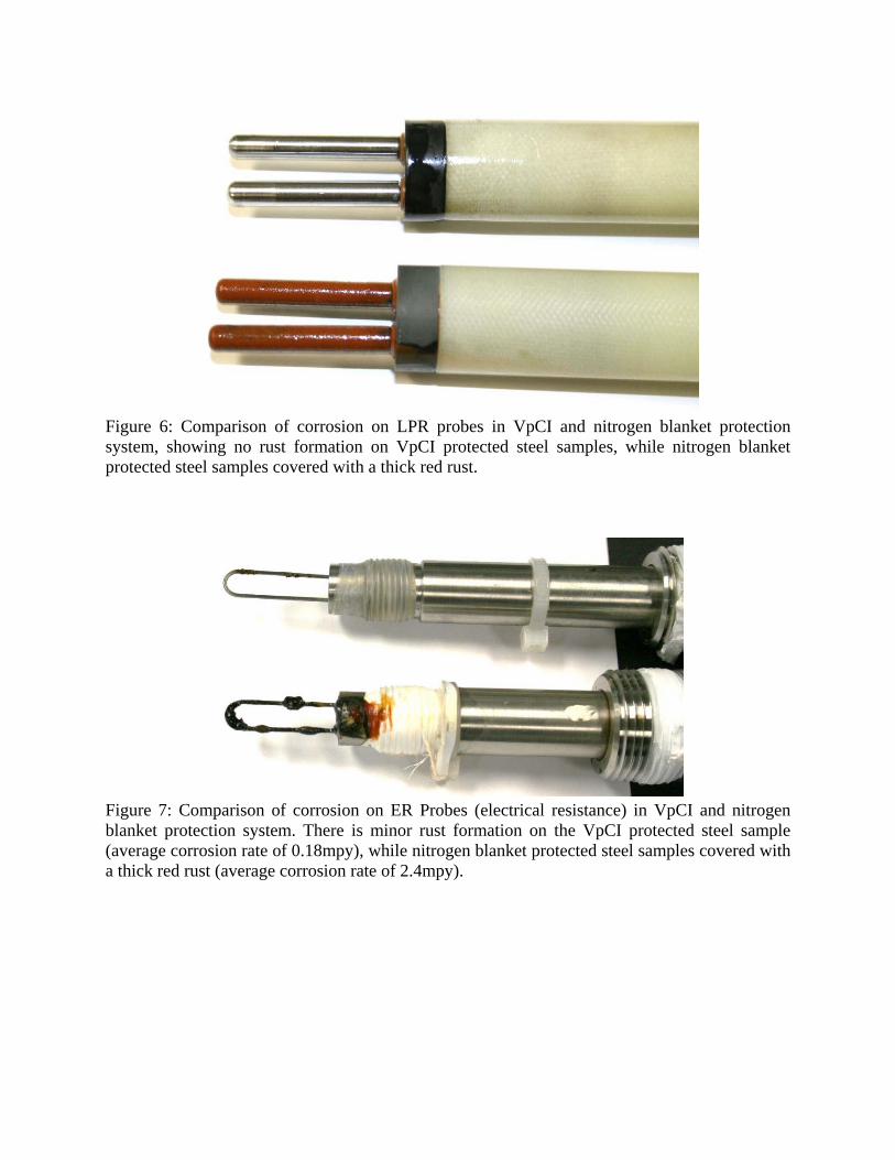
Figure 6: Comparison of corrosion on LPR probes in VpCI and nitrogen blanket protection system, showing no rust formation on VpCI protected steel samples, while nitrogen blanket protected steel samples covered with a thick red rust.
Figure 7: Comparison of corrosion on ER Probes (electrical resistance) in VpCI and nitrogen blanket protection system. There is minor rust formation on the VpCI protected steel sample (average corrosion rate of 0.18mpy), while nitrogen blanket protected steel samples covered with a thick red rust (average corrosion rate of 2.4mpy).
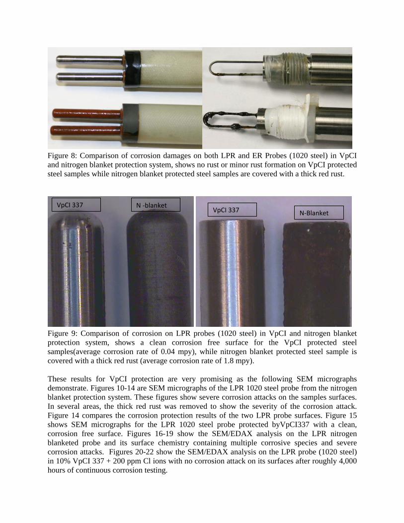
Figure 8: Comparison of corrosion damages on both LPR and ER Probes (1020 steel) in VpCI and nitrogen blanket protection system, shows no rust or minor rust formation on VpCI protected steel samples while nitrogen blanket protected steel samples are covered with a thick red rust.
Figure 9: Comparison of corrosion on LPR probes (1020 steel) in VpCI and nitrogen blanket protection system, shows a clean corrosion free surface for the VpCI protected steel samples(average corrosion rate of 0.04 mpy), while nitrogen blanket protected steel sample is covered with a thick red rust (average corrosion rate of 1.8 mpy). These results for VpCI protection are very promising as the following SEM micrographs demonstrate. Figures 10-14 are SEM micrographs of the LPR 1020 steel probe from the nitrogen blanket protection system. These figures show severe corrosion attacks on the samples surfaces. In several areas, the thick red rust was removed to show the severity of the corrosion attack. Figure 14 compares the corrosion protection results of the two LPR probe surfaces. Figure 15 shows SEM micrographs for the LPR 1020 steel probe protected byVpCI337 with a clean, corrosion free surface. Figures 16-19 show the SEM/EDAX analysis on the LPR nitrogen blanketed probe and its surface chemistry containing multiple corrosive species and severe corrosion attacks. Figures 20-22 show the SEM/EDAX analysis on the LPR probe (1020 steel) in 10% VpCI 337 + 200 ppm Cl ions with no corrosion attack on its surfaces after roughly 4,000 hours of continuous corrosion testing.
VpCI 337 N -blanket VpCI 337 N-Blanket
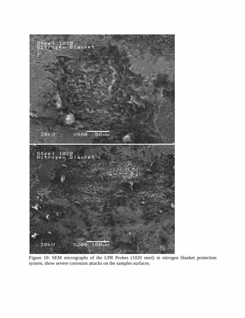
Figure 10: SEM micrographs of the LPR Probes (1020 steel) in nitrogen blanket protection system, show severe corrosion attacks on the samples surfaces.

Figure 11: SEM micrographs of the LPR Probes (1020 steel) in nitrogen blanket protection system, show severe corrosion attacks on the sample surfaces. The thick red rust was removed to show severity of corrosion attack.
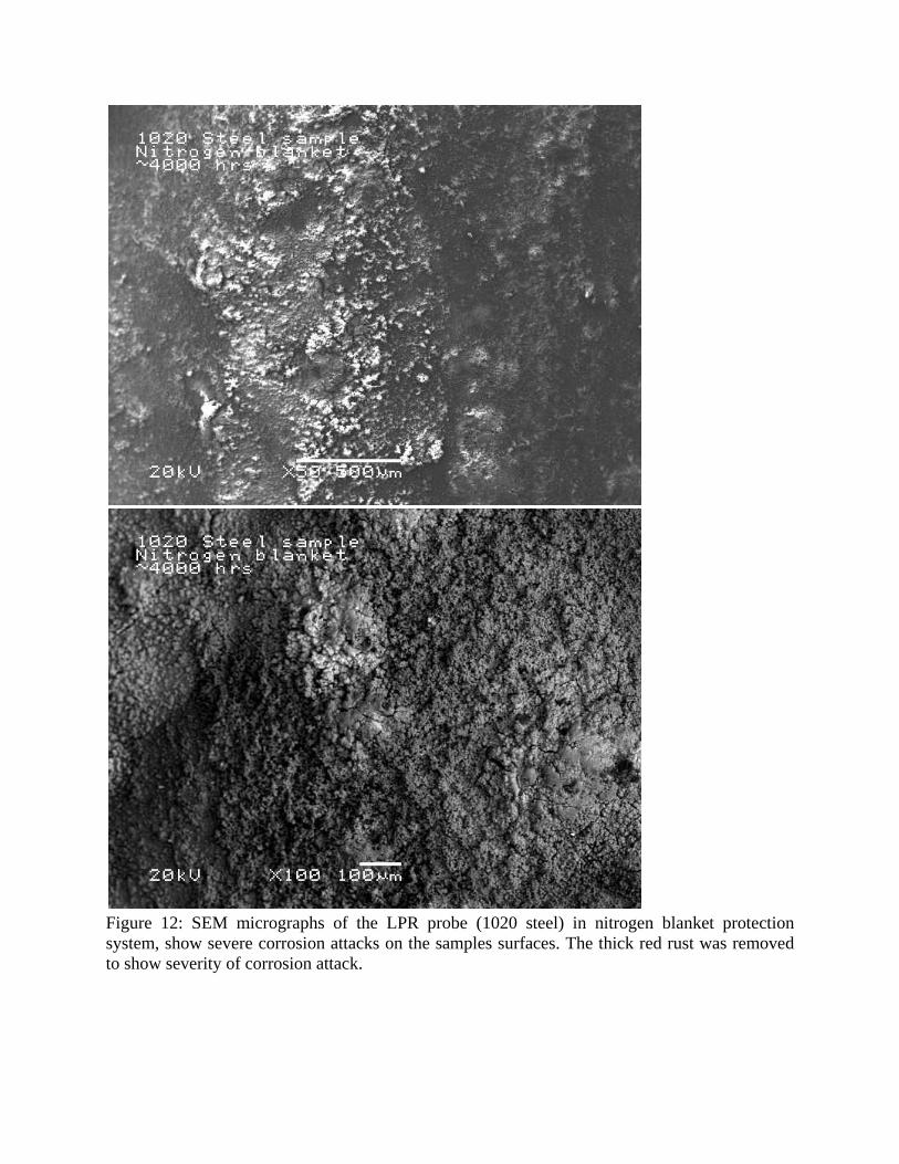
Figure 12: SEM micrographs of the LPR probe (1020 steel) in nitrogen blanket protection system, show severe corrosion attacks on the samples surfaces. The thick red rust was removed to show severity of corrosion attack.
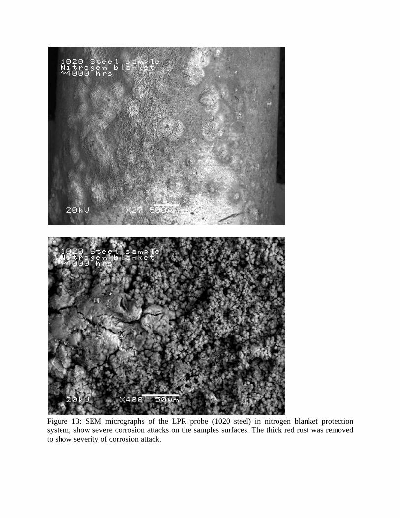
Figure 13: SEM micrographs of the LPR probe (1020 steel) in nitrogen blanket protection system, show severe corrosion attacks on the samples surfaces. The thick red rust was removed to show severity of corrosion attack.
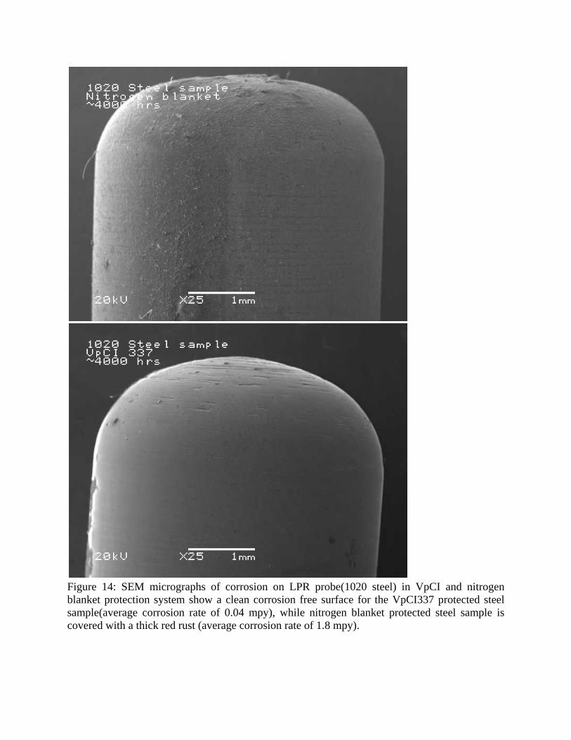
Figure 14: SEM micrographs of corrosion on LPR probe(1020 steel) in VpCI and nitrogen blanket protection system show a clean corrosion free surface for the VpCI337 protected steel sample(average corrosion rate of 0.04 mpy), while nitrogen blanket protected steel sample is covered with a thick red rust (average corrosion rate of 1.8 mpy).
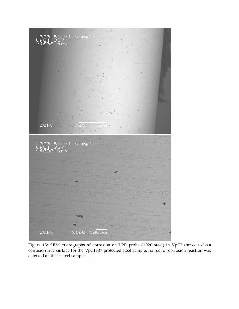
Figure 15: SEM micrographs of corrosion on LPR probe (1020 steel) in VpCI shows a clean corrosion free surface for the VpCI337 protected steel sample, no rust or corrosion reaction was detected on these steel samples.

Weight %
O-K Na-K Al-K Si-K S-K Cl-K K-K Ca-K Fe-K N-steel(1)_pt1 18.62 2.92 0.39 3.29 0.60 1.41 0.66 1.13 70.97 Figure 16: SEM/EDAX analysis on the LPR probe (1020 steel) in nitrogen blanket protection system shows severe corrosion attacks on the sample surfaces.
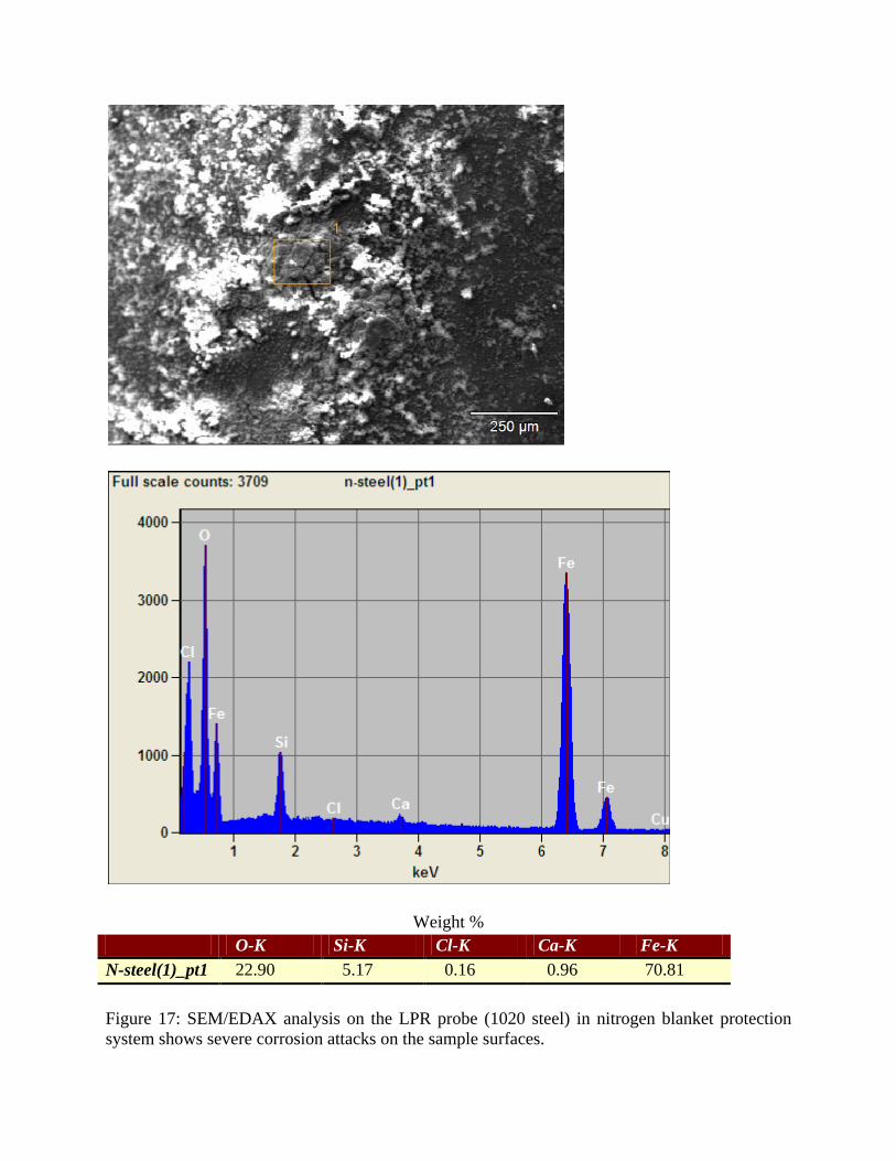
Weight % O-K Si-K Cl-K Ca-K Fe-K N-steel(1)_pt1 22.90 5.17 0.16 0.96 70.81 Figure 17: SEM/EDAX analysis on the LPR probe (1020 steel) in nitrogen blanket protection system shows severe corrosion attacks on the sample surfaces.
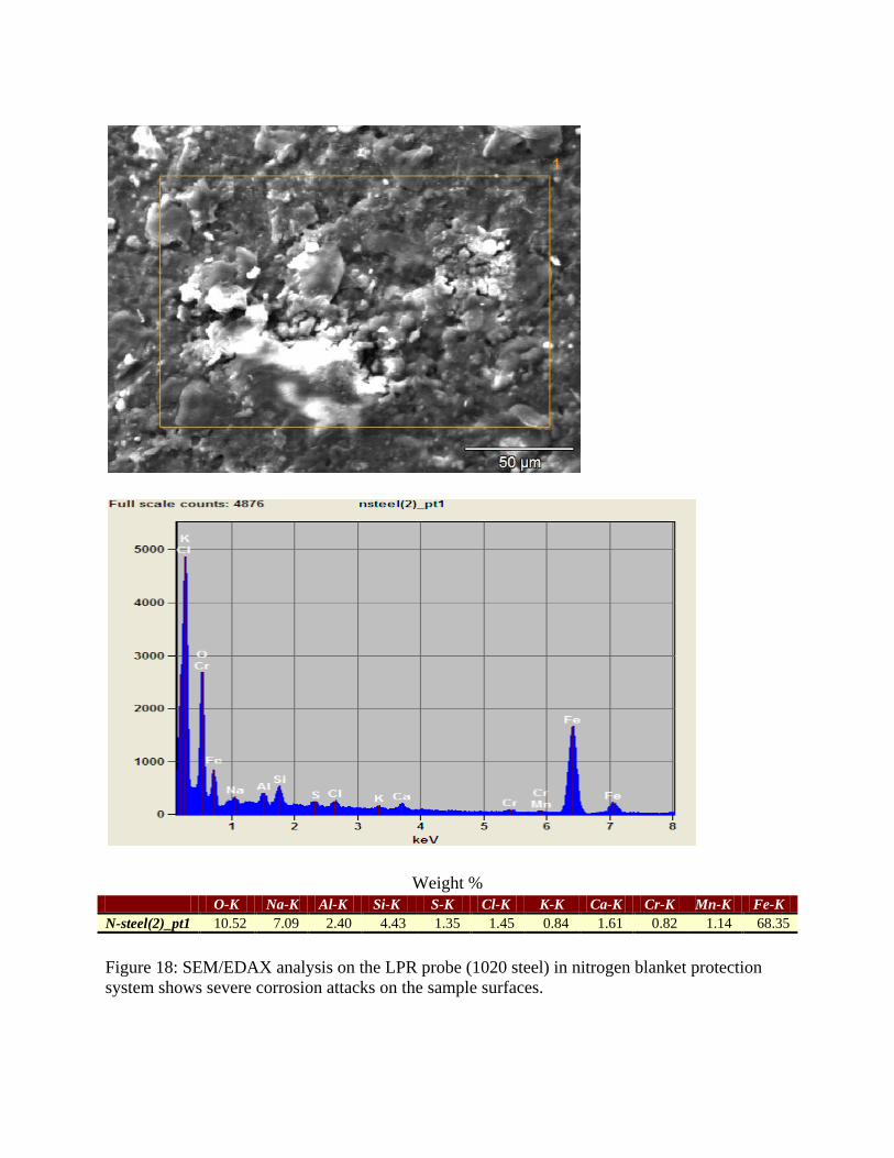
Weight % O-K Na-K Al-K Si-K S-K Cl-K K-K Ca-K Cr-K Mn-K Fe-K N-steel(2)_pt1 10.52 7.09 2.40 4.43 1.35 1.45 0.84 1.61 0.82 1.14 68.35 Figure 18: SEM/EDAX analysis on the LPR probe (1020 steel) in nitrogen blanket protection system shows severe corrosion attacks on the sample surfaces.
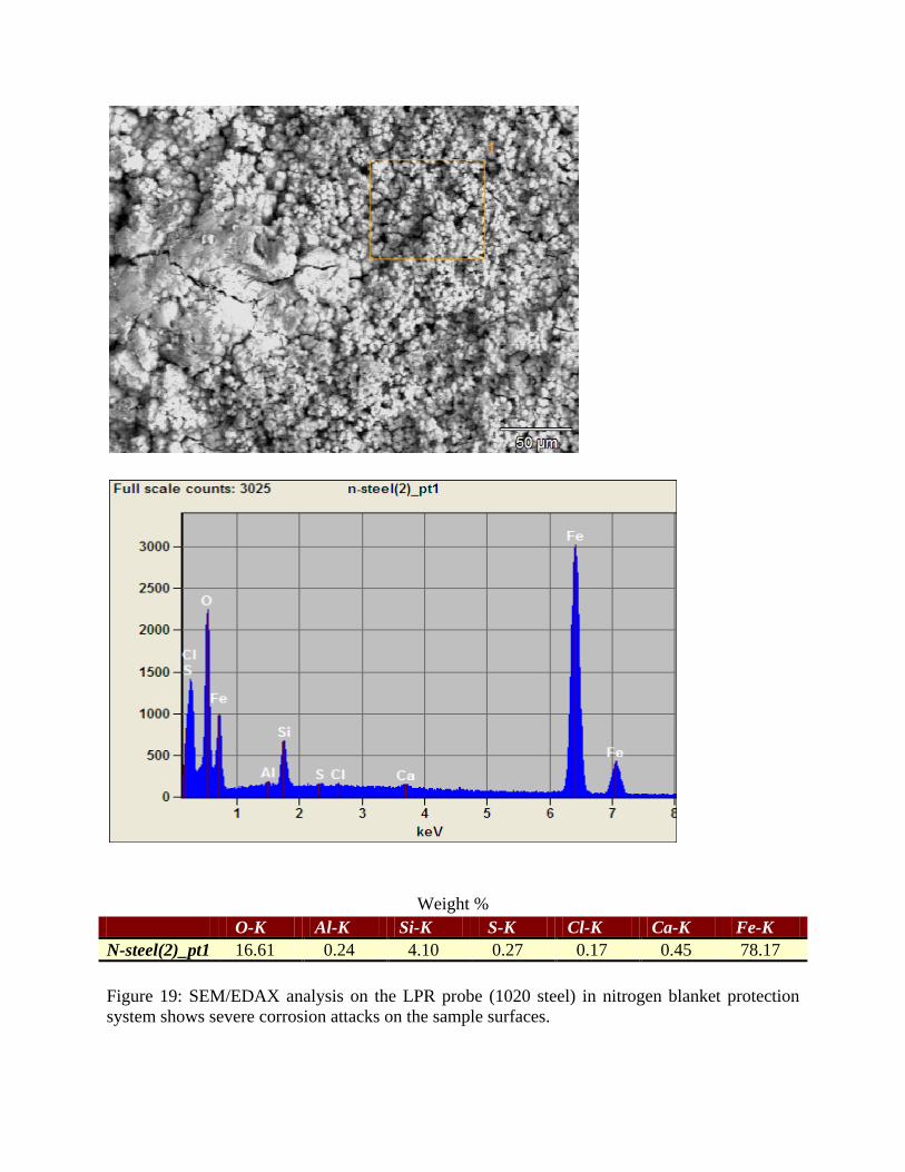
Weight % O-K Al-K Si-K S-K Cl-K Ca-K Fe-K N-steel(2)_pt1 16.61 0.24 4.10 0.27 0.17 0.45 78.17 Figure 19: SEM/EDAX analysis on the LPR probe (1020 steel) in nitrogen blanket protection system shows severe corrosion attacks on the sample surfaces.
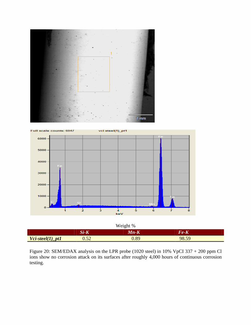
Weight % Si-K Mn-K Fe-K Vci-steel(1)_pt1 0.52 0.89 98.59 Figure 20: SEM/EDAX analysis on the LPR probe (1020 steel) in 10% VpCI 337 + 200 ppm Cl ions show no corrosion attack on its surfaces after roughly 4,000 hours of continuous corrosion testing.
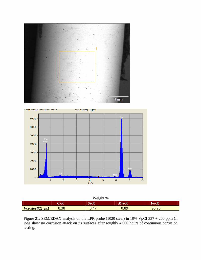
Weight % C-K Si-K Mn-K Fe-K Vci-steel(2)_pt1 8.38 0.47 0.89 90.26 Figure 21: SEM/EDAX analysis on the LPR probe (1020 steel) in 10% VpCI 337 + 200 ppm Cl ions show no corrosion attack on its surfaces after roughly 4,000 hours of continuous corrosion testing.
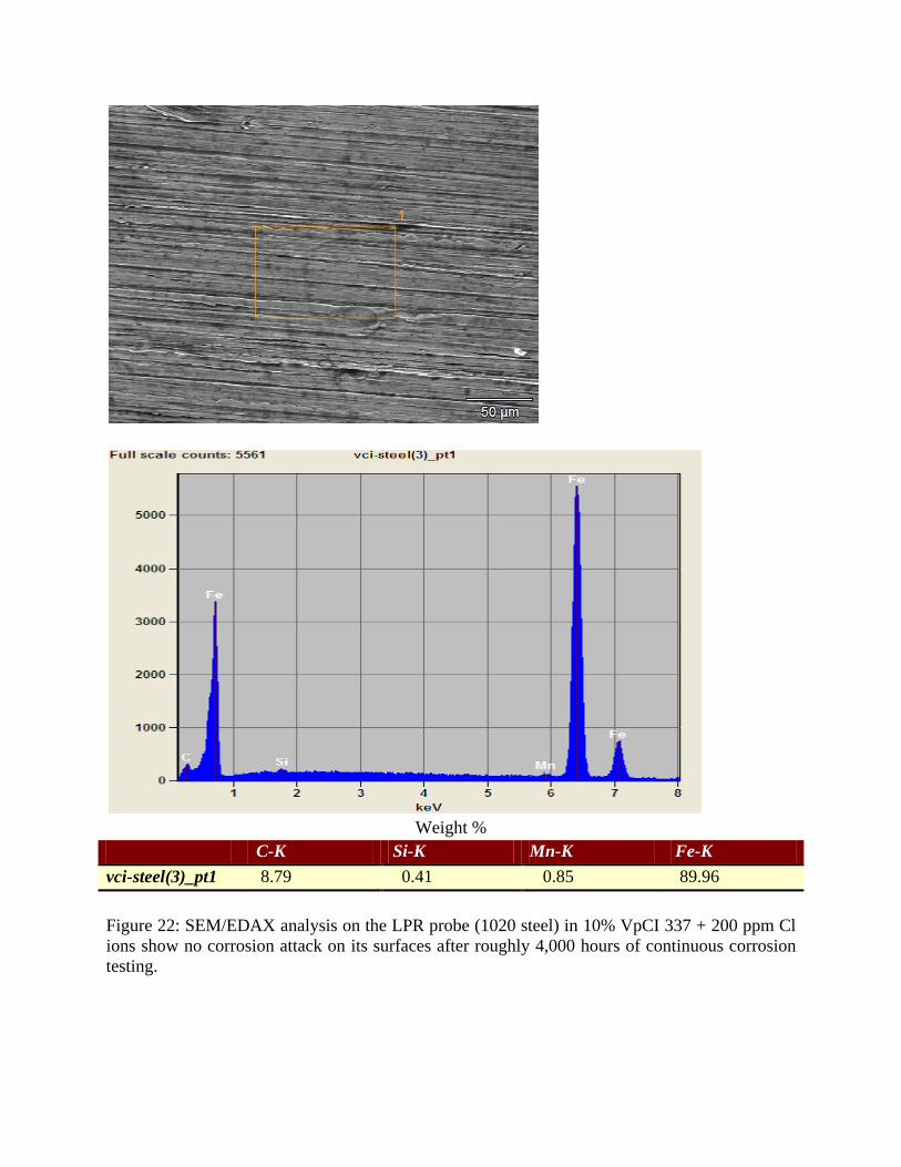
Weight %
C-K Si-K Mn-K Fe-K vci-steel(3)_pt1 8.79 0.41 0.85 89.96 Figure 22: SEM/EDAX analysis on the LPR probe (1020 steel) in 10% VpCI 337 + 200 ppm Cl ions show no corrosion attack on its surfaces after roughly 4,000 hours of continuous corrosion testing.
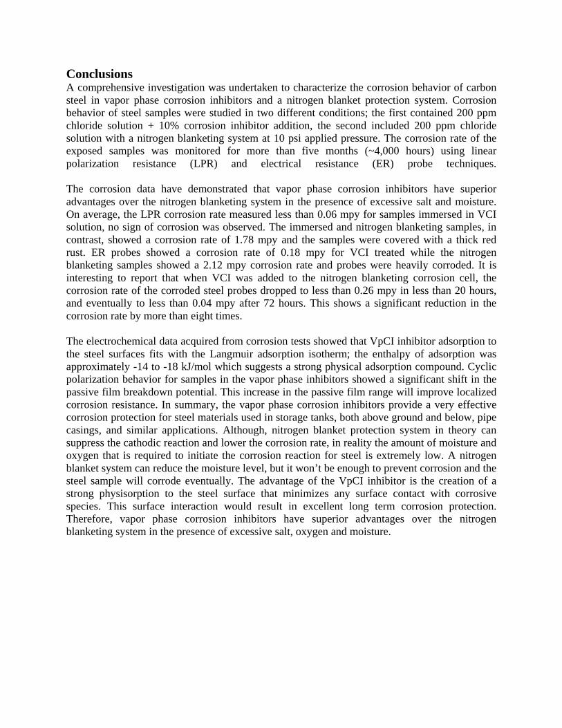
Conclusions A comprehensive investigation was undertaken to characterize the corrosion behavior of carbon steel in vapor phase corrosion inhibitors and a nitrogen blanket protection system. Corrosion behavior of steel samples were studied in two different conditions; the first contained 200 ppm chloride solution + 10% corrosion inhibitor addition, the second included 200 ppm chloride solution with a nitrogen blanketing system at 10 psi applied pressure. The corrosion rate of the exposed samples was monitored for more than five months (~4,000 hours) using linear polarization resistance (LPR) and electrical resistance (ER) probe techniques. The corrosion data have demonstrated that vapor phase corrosion inhibitors have superior advantages over the nitrogen blanketing system in the presence of excessive salt and moisture. On average, the LPR corrosion rate measured less than 0.06 mpy for samples immersed in VCI solution, no sign of corrosion was observed. The immersed and nitrogen blanketing samples, in contrast, showed a corrosion rate of 1.78 mpy and the samples were covered with a thick red rust. ER probes showed a corrosion rate of 0.18 mpy for VCI treated while the nitrogen blanketing samples showed a 2.12 mpy corrosion rate and probes were heavily corroded. It is interesting to report that when VCI was added to the nitrogen blanketing corrosion cell, the corrosion rate of the corroded steel probes dropped to less than 0.26 mpy in less than 20 hours, and eventually to less than 0.04 mpy after 72 hours. This shows a significant reduction in the corrosion rate by more than eight times. The electrochemical data acquired from corrosion tests showed that VpCI inhibitor adsorption to the steel surfaces fits with the Langmuir adsorption isotherm; the enthalpy of adsorption was approximately -14 to -18 kJ/mol which suggests a strong physical adsorption compound. Cyclic polarization behavior for samples in the vapor phase inhibitors showed a significant shift in the passive film breakdown potential. This increase in the passive film range will improve localized corrosion resistance. In summary, the vapor phase corrosion inhibitors provide a very effective corrosion protection for steel materials used in storage tanks, both above ground and below, pipe casings, and similar applications. Although, nitrogen blanket protection system in theory can suppress the cathodic reaction and lower the corrosion rate, in reality the amount of moisture and oxygen that is required to initiate the corrosion reaction for steel is extremely low. A nitrogen blanket system can reduce the moisture level, but it won’t be enough to prevent corrosion and the steel sample will corrode eventually. The advantage of the VpCI inhibitor is the creation of a strong physisorption to the steel surface that minimizes any surface contact with corrosive species. This surface interaction would result in excellent long term corrosion protection. Therefore, vapor phase corrosion inhibitors have superior advantages over the nitrogen blanketing system in the presence of excessive salt, oxygen and moisture.
Acknowledgment: The authors would like to express their appreciation to the W.M. Keck Foundation, Department of Education/AIMS2 program and Cortec Corp. for their sponsorship of this project. References: [1] Z. Ahmad, Principles of Corrosion Engineering and Corrosion Control, Elsevier 2006. [2] G. E. Fodor, the Inhibition of Vapor-Phase Corrosion: A Review, Interim Report BFLRF No. 209, Belvoir Fuels and Lubricants Research Facility, SWRI 1985. [3] Cortec website brochures on VpCI 337; http://www.cortecvci.com. [4] J. Holden, Andrea Hansen, Alla Furman, Rita Kharshan and Elizabeth Austin, Vapor Corrosion inhibitors in Hydro-testing and long term Storage applications, CORROSION/2010, paper # 10405, NACE International, Houston, TX., 2010. [5] Boris M. Miksic, Alla Y. Furman, Margarita A. Kharshan, Effectiveness of the Corrosion Inhibitors for Petroleum Industry under Various Flow conditions, CORROSION/2009, paper no. 09573, NACE International, Houston, TX, 2009. [6] M. Kharshan, and C. Cracauer, Applications for Biodegradable Vapor Phase Corrosion Inhibitors; MP, NACE International March 2011, [7] Yew C. Chang and B.A. Miksic, Environmentally Friendly VCI Systems, CORROSION/99, paper no. 93, NACE International, Houston, TX. [8] C. Chandler, A. Furman, M. Kharshan, VCIs—A Novel Approach to Corrosion Control in the Water Treatment Industry WATERTECH, 1995. [9] J. Mose, F. Holcer, Z. Culig, S. Lafta, M. Ivanusic, Volatile Corrosion Inhibitors Used for Conservation of Refinery Equipment and Facilities, Denver, CO, March 1996. [10] L. Gelner, Protection of Storage Tank Bottoms Using Volatile Corrosion Inhibitors (VCI), NACE Middle East Regional Conference, 1996. [11] A. Furman, M. Kharshan, Methodology of VCIs for Water Treatment, CORROSION/97, paper no. 182, NACE International, Houston, TX, 1997. [12] A. Furman, M. Kharshan, Efficiency of Contact and Volatile Corrosion Inhibitors for Gas and Oil Transmission Lines CORROSION/98, paper no. 236, NACE International, Houston, TX.1998. [13] C. Chandler, Biodegradable Volatile Corrosion Inhibitors 9th European Symposium on Corrosion Inhibitors, Italy, 2000. [14] B.A. Miksic, R.H. Miller, Fundamental Principals of Corrosion Protection with Vapor Phase Inhibitors, 5th European Symposium on Corrosion Inhibitors, Italy, 1980. [15] C.G. Moore, B.A. Miksic, Vapor Corrosion Inhibitors, CORROSION/95, paper no. 490, NACE: Houston, TX, 1995. [17] B.A. Miksic, Migratory VCI Inhibitors for Wet Thermal Insulation CORROSION/89, paper no. 344, NACE International, Houston, TX, 1989. [18] A.B. Hughes, M.C. Larkin, Corrosion Inhibited in Steel Vessel Stored Outdoors, Plant Services Magazine, August 1987.
[19] C. Kraemer, A Procedure for Testing the Effect of Vapor Phase Corrosion Inhibitors on Combined Multi Metals CORROSION/97, paper no. 178, NACE International, Houston, TX. [20] B. Rudman, A Comparison of Several Corrosion Inhibiting Papers in Various Environments, CORROSION/98, paper no. 237, NACE International, Houston, TX.1998. [21] A. Furman, C. Chandler, Test Methods for Vapor Corrosion Inhibitors, 9th European Symposium on Corrosion Inhibitors, Italy, 2000. [22] B. Bavarian, J. Zhang and L. Reiner, SCC and Crevice Corrosion Inhibition of Steam Turbines ASTM A470 and AA7050 Al-alloys using VCI, NACE Corrosion 2012 Conference, March 2012. [23] B. Bavarian, L. Reiner and H. Youssefpour, Vapor Phase Inhibitors to Extend the Life of Aging Aircraft, NACE Corrosion 2005, paper # 05329. [24] W. Durine, R. D Marco, A. Jefferson, and B. Kinsella, JES, 146 (5) 1751-1756 (1999). [25] R. Gasparac, C. R. Martin and E. Stupnisek-Lisac, “In situ Studies of Imidazole and its derivatives as Copper Corrosion Inhibitors,” Journal of The Electrochemical Society, 147 (2) 548-551 (2000). [26] 9030 Plus™ Corrater® Instrument User Manual P/N 710680; manual Rev. E (12/07). [27] Metal Samples Corrosion Monitoring Systems Manual for MS3500E/3510E Remote ER Data Logger.www.metalsamples.com. [28] M. L. Free, A new corrosion inhibition model for surfactants that more closely accounts for actual adsorption than traditional models that assume physical coverage is proportional to inhibition, Corrosion Science, 10 May 2004. [29] M. Lagrenée, B. Mernari, M. Bouanis, M. Traisnel and F. Bentiss, Study of the mechanism and inhibiting efficiency of 3,5-bis(4-methylthiophenyl)-4H-1,2,4-triazole on mild steel corrosion in acidic media, Corrosion Science, Vol 44, Issue 3, March 2002. [30] F. Bentiss, B. Mernari, M. Traisnel, H. Vezin and M. Lagrenée, On the relationship between corrosion inhibiting effect and molecular structure of 2,5-bis(n-pyridyl)-1,3,4-thiadiazole derivatives in acidic media: AC Impedance and DFT studies, Corrosion Science 53 (2011).