superb accelerator & ilc superb accelerator & ilc m. e. biagini, lnf-infn for the superb...
TRANSCRIPT
SuperB AcceleratorSuperB Accelerator& ILC& ILC
M. E. Biagini, LNF-INFNfor the SuperB Team
ILC GDE visit, LNF, Jan. 22th 2008
D. Alesini, M. E. Biagini, R. Boni, M. Boscolo, A. Drago, S. Guiducci, G. Mazzitelli, M. Preger, P. Raimondi, S. Tomassini, C. Vaccarezza, M. Zobov (INFN/LNF, Italy)
K. Bertsche, Y. Cai, A. Fisher, S. Heifets, A. Novokhatski, M.T. Pivi, J. Seeman, M. Sullivan, U. Wienands, W. Wittmer (SLAC, US)
T. Agoh, K. Ohmi, Y. Ohnishi (KEK, Japan) I. Koop, S. Nikitin, E. Levichev, P. Piminov, D. Shatilov (BINP, Russia)
G. Bassi, A. Wolski (Cockcroft, UK)M. Venturini (LBNL, US)
S. Bettoni (CERN, Switzerland)Variola (LAL, France)
E. Paoloni, G. Marchiori (Pisa Univ., Italy)
2
SuperB is an international enterprise aiming at the construction of a very high luminosity (1036 cm-2 s-1) asymmetric e+e- Flavor Factory, with location at the campus of the University of Rome Tor Vergata, near the INFN Frascati National LaboratoryAims: Very high luminosity
• Desire 1036: experimenters say 1035 will not get to the physics soon enough.
High reliability • The goal is integrated luminosity!
Polarized e- at IP • This is a relatively new addition by the users.
Ability to collide at Y4S and lower energy (~J/Psi)• For maximum number of experimenters.
A Conceptual Design Report, signed by 85 Institutions was published in March 2007 (arXiv:0709.0451 [hep-ex])
SuperB: a SuperB: a 10103636 cm cm-2-2 s s-1 -1 acceleratoraccelerator
3
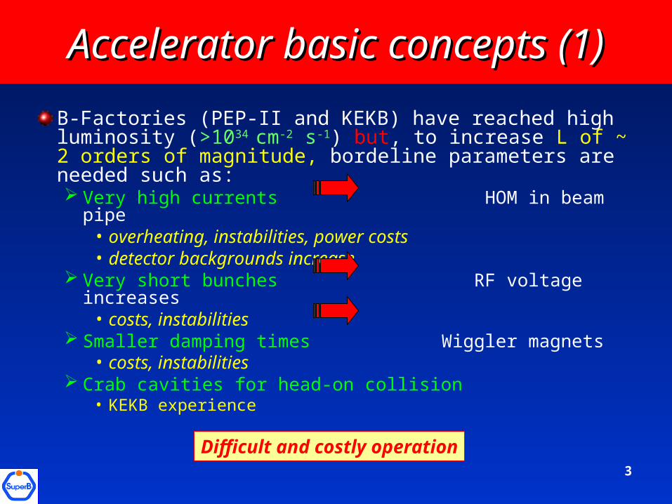
B-Factories (PEP-II and KEKB) have reached high luminosity (>1034 cm-2 s-1) but, to increase L of ~ 2 orders of magnitude, bordeline parameters are needed such as: Very high currents HOM in beam pipe
• overheating, instabilities, power costs• detector backgrounds increase
Very short bunches RF voltage increases • costs, instabilities
Smaller damping times Wiggler magnets• costs, instabilities
Crab cavities for head-on collision • KEKB experience
Accelerator basic concepts (1)Accelerator basic concepts (1)
Difficult and costly operation
4
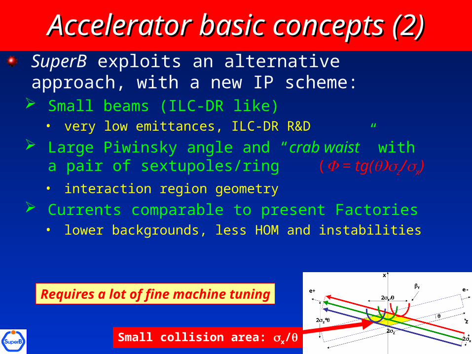
SuperB exploits an alternative approach, with a new IP scheme:
Small beams (ILC-DR like)• very low emittances, ILC-DR R&D
Large Piwinsky angle and “crab waist” with a pair of sextupoles/ring ( = tg(z/x)• interaction region geometry
Currents comparable to present Factories• lower backgrounds, less HOM and instabilities
Basic concepts (2)Basic concepts (2)
Requires a lot of fine machine tuning
Small collision area: x/
Accelerator basic concepts (2)Accelerator basic concepts (2)
5
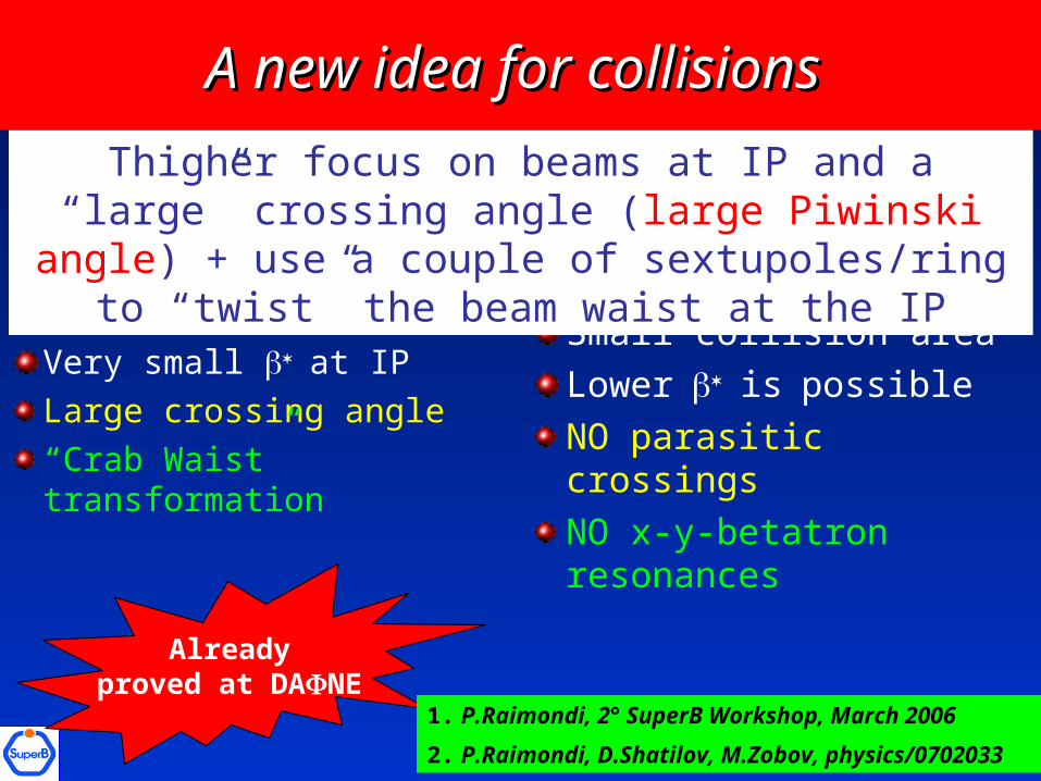
Ultra-low emittance
Very small at IP
Large crossing angle
“Crab Waist” transformation
Small collision area
Lowerispossible
NO parasitic crossings
NO x-y-betatron resonances
Thigher focus on beams at IP and a “large” crossing angle (large Piwinski angle) + use a couple of
sextupoles/ring to “twist” the beam waist at the IP
Alreadyproved at DANE
A new idea for collisions A new idea for collisions
1. P.Raimondi, 2° SuperB Workshop, March 2006
2. P.Raimondi, D.Shatilov, M.Zobov, physics/0702033
6
Relatively easier to make small x with respect to short z
Problem of parasitic collisions automatically solved due to higher crossing angle and smaller horizontal beam sizeThere is no need to increase excessively beam current and to decrease the bunch length: Beam instabilities are less severeManageable HOM heatingNo coherent synchrotron radiation of short bunchesNo excessive power consumption
and...and...
7
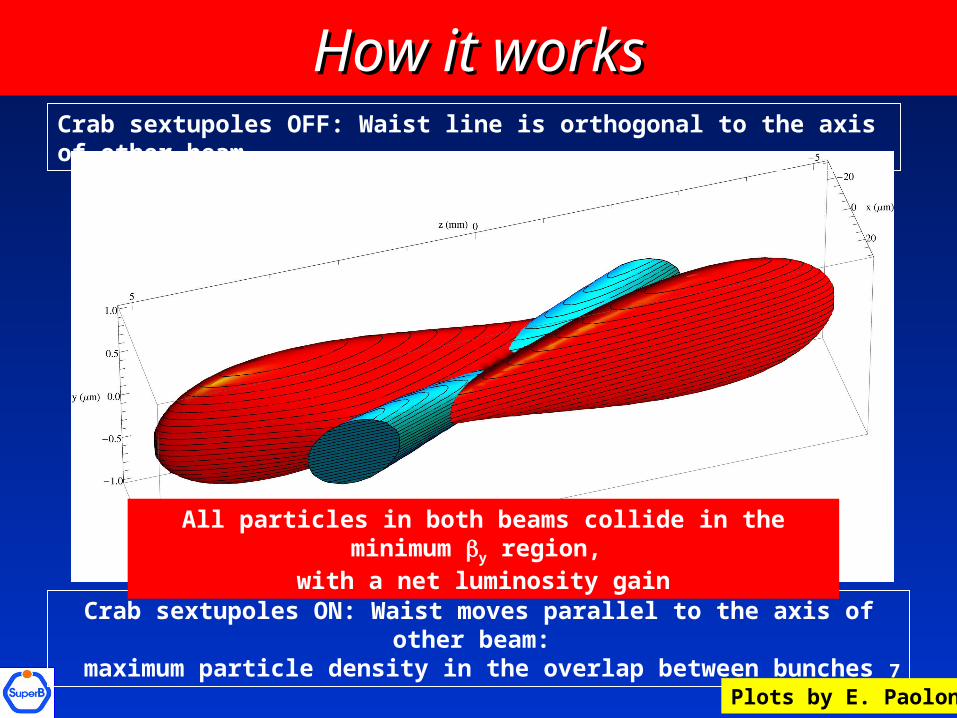
How it worksHow it worksCrab sextupoles OFF: Waist line is orthogonal to the axis of other beam
Crab sextupoles ON: Waist moves parallel to the axis of other beam: maximum particle density in the overlap between bunches
Plots by E. Paoloni
All particles in both beams collide in the minimum y region, with a net luminosity gain
8
0 0.2 0.4 0.6 0.8 1
0
0.2
0.4
0.6
0.8
1
0 0.2 0.4 0.6 0.8 1
0
0.2
0.4
0.6
0.8
1
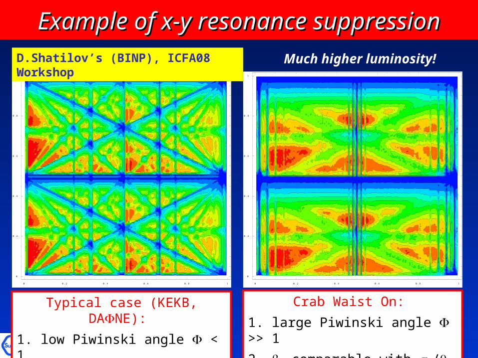
Typical case (KEKB, DANE):
1. low Piwinski angle < 1
2. y comparable with z
Crab Waist On:
1. large Piwinski angle >> 1
2. y comparable with x/
Much higher luminosity!D.Shatilov’s (BINP), ICFA08 Workshop
Example of x-y resonance suppressionExample of x-y resonance suppression
9
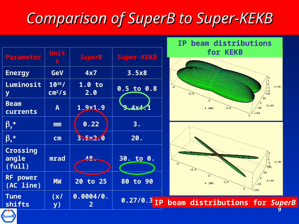
Comparison of SuperB to Super-KEKBComparison of SuperB to Super-KEKB
Parameter Units SuperB Super-KEKB
Energy GeV 4x7 3.5x8
Luminosity1036/
cm2/s1.0 to 2.0 0.5 to 0.8
Beam currents
A 1.9x1.9 9.4x4.1
y* mm 0.22 3.
x* cm 3.5x2.0 20.
Crossing angle (full)
mrad 48. 30. to 0.
RF power (AC line)
MW 20 to 25 80 to 90
Tune shifts (x/y) 0.0004/0.2 0.27/0.3
IP beam distributions for KEKB
IP beam distributions for SuperB
10
SuperB main featuresSuperB main features
Goal: maximize luminosity while keeping wall power low
2 rings (4x7 GeV) design: flexible but challenging Ultra low emittance optics: 7x4 pm vertical emittanceBeam currents: comparable to present Factories Crossing angle and “crab waist” used to maximize luminosity and minimize beam size blow-upPresently under test at DANE
No “emittance” wigglers used in Phase 1 (save in power)Design based on recycling PEP-II hardware (corresponds to a lot of money)Longitudinal polarization for e- in the HER is included (unique feature)
11
Lattice overview (1)Lattice overview (1)
The lattice for SuperB rings needs to comply with several issues: small emittances asymmetric energies insertion of a Final Focus (similar to ILC), with very small * large dynamic aperture & long lifetimes spin rotator section in HER
The new large crossing angle & small collision parameters scheme with “crab waist” has relaxed the requests on the bunch lengths and beam currents
Main objective is to design a lattice that can deliver 1x1036 luminosity while keeping wall power requirements as low as possible
12
Lattice overview (2)Lattice overview (2)
First design was derived by ILC-DR OCS lattice with TME cells and ILC-like Final Focus, but shorter ringsThen a solution using the PEP-II hardware and smaller intrinsic emittance (higher x-phase advance in a cell) was designedThe present layout has small emittances (1.6 nm/4 pm (HER x/y) and 2.8 nm/7 pm (LER x/y)) and 20 msec longitudinal damping times without insertion of wiggler magnetsHowever space is provided for wiggler installations whenever needed (ex. luminosity upgrade option)

13
Ring optical functionsRing optical functions
LER
HER
No spin rotator
here
14
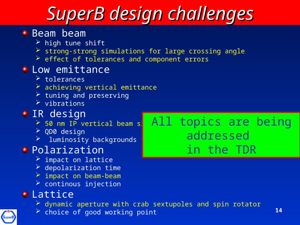
SuperB design challengesSuperB design challengesBeam beam high tune shift strong-strong simulations for large crossing angle effect of tolerances and component errors
Low emittance tolerances achieving vertical emittance tuning and preserving vibrations
IR design 50 nm IP vertical beam size QD0 design luminosity backgrounds
Polarization impact on lattice depolarization time impact on beam-beam continous injection
Lattice dynamic aperture with crab sextupoles and spin rotator choice of good working point
All topics are being addressed in the TDR

15
Low emittance tuningLow emittance tuning
VERY important in SuperB, since design y is 7 and 4 pm Contributions to y come mainly from: tilts in quadrupoles misaligned sextupoles vertical dispersion beam coupling IBS trickle injection beam instabilities
Computer modeling as well as diagnostics will help in achieving and maintaining y
This work has just started, luckily we can profit of work performed for, and experience at, ATF, SLS, CESR-TA and ILC-DR
16
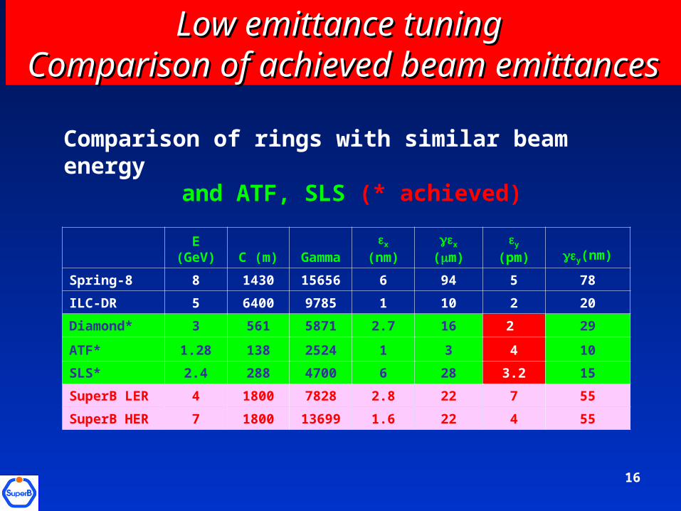
Low emittance tuning Low emittance tuning Comparison of achieved beam emittancesComparison of achieved beam emittances
E (GeV) C (m) Gamma x (nm) x (m) y (pm) y(nm)
Spring-8 8 1430 15656 6 94 5 78
ILC-DR 5 6400 9785 1 10 2 20
Diamond* 3 561 5871 2.7 16 2 29
ATF* 1.28 138 2524 1 3 4 10
SLS* 2.4 288 4700 6 28 3.2 15
SuperB LER 4 1800 7828 2.8 22 7 55
SuperB HER 7 1800 13699 1.6 22 4 55
Comparison of rings with similar beam energyand ATF, SLS (* achieved)
17
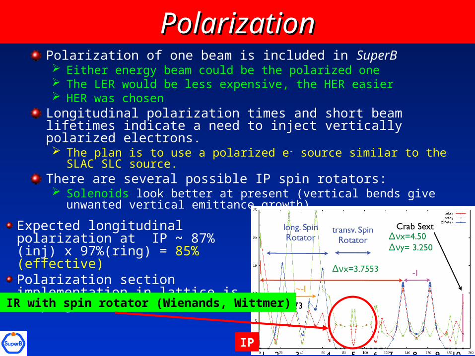
PolarizationPolarizationPolarization of one beam is included in SuperB Either energy beam could be the polarized one The LER would be less expensive, the HER easier HER was chosen
Longitudinal polarization times and short beam lifetimes indicate a need to inject vertically polarized electrons. The plan is to use a polarized e- source similar to the SLAC SLC source.
There are several possible IP spin rotators: Solenoids look better at present (vertical bends give unwanted vertical
emittance growth)
Expected longitudinal polarization at IP ~ 87%(inj) x 97%(ring) = 85%(effective)Polarization section implementation in lattice is in progress
IP
Half IR with spin rotator (Wienands, Wittmer)
18
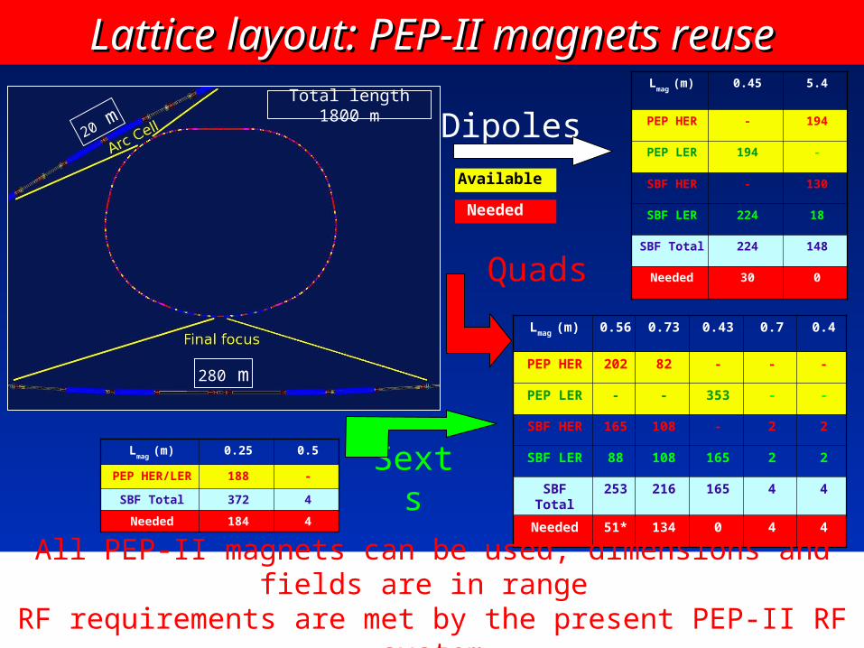
Total length 1800 m
280 m
20 m
Lmag
(m) 0.45 5.4
PEP HER - 194
PEP LER 194 -
SBF HER - 130
SBF LER 224 18
SBF Total 224 148
Needed 30 0
Dipoles
Lmag (m) 0.56 0.73 0.43 0.7 0.4
PEP HER 202 82 - - -
PEP LER - - 353 - -
SBF HER 165 108 - 2 2
SBF LER 88 108 165 2 2
SBF Total 253 216 165 4 4
Needed 51* 134 0 4 4
Quads
Available
Needed
All PEP-II magnets can be used, dimensions and fields are in range
RF requirements are met by the present PEP-II RF system
Lmag
(m) 0.25 0.5
PEP HER/LER 188 -
SBF Total 372 4
Needed 184 4
Sexts
Lattice layout: PEP-II magnets reuseLattice layout: PEP-II magnets reuse
19
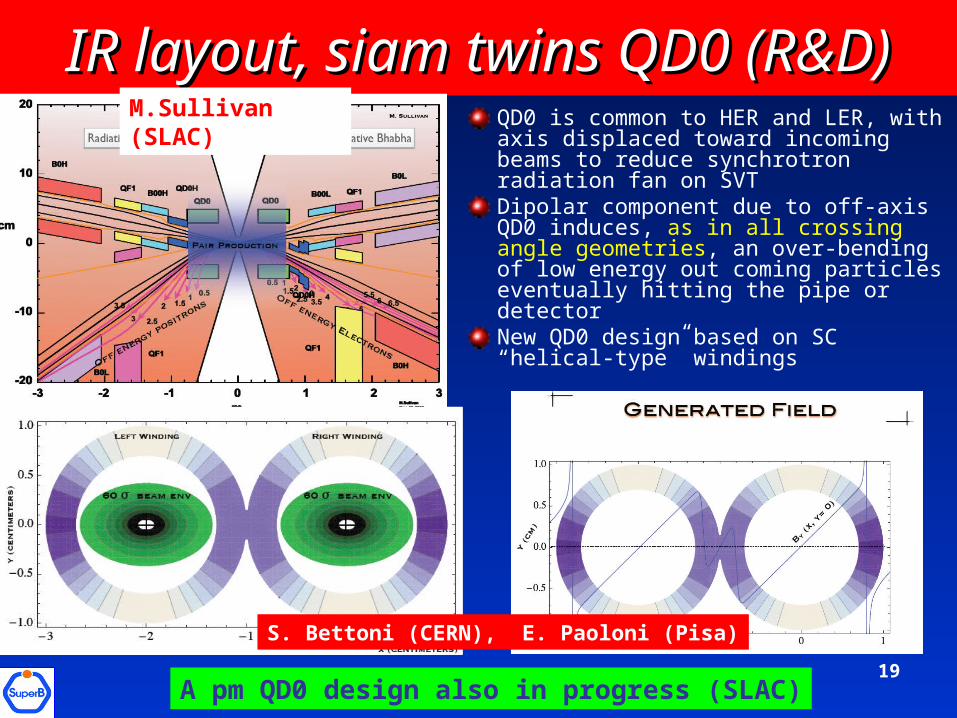
IR layout, siam twins QD0 (R&D)IR layout, siam twins QD0 (R&D)QD0 is common to HER and LER, with axis displaced toward incoming beams to reduce synchrotron radiation fan on SVTDipolar component due to off-axis QD0 induces, as in all crossing angle geometries, an over-bending of low energy out coming particles eventually hitting the pipe or detectorNew QD0 design based on SC “helical-type” windings
M.Sullivan (SLAC)
S. Bettoni (CERN), E. Paoloni (Pisa)
A pm QD0 design also in progress (SLAC)
20
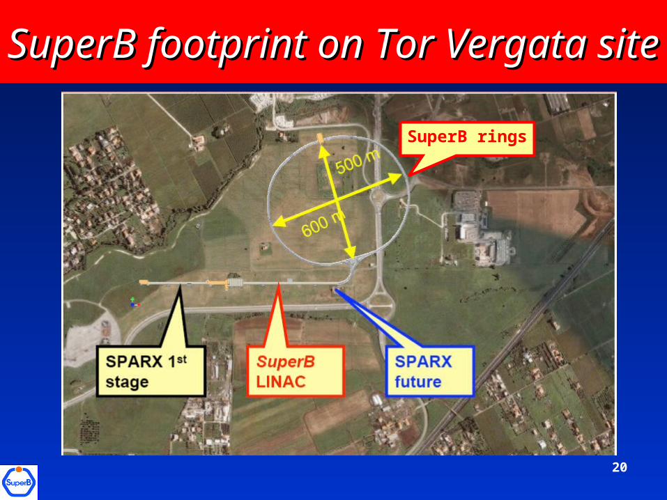
SuperB footprint on Tor Vergata siteSuperB footprint on Tor Vergata site
SuperB rings
21
Synergy with the ILC (1)Synergy with the ILC (1)
ILC-DR and SuperB will face similar demands on beam quality and stability: SuperB for direct production of luminosity, and ILC-DR for reliable tuning and operation of the downstream systems, for luminosity production from the extracted beamsThere are significant similarities between SuperB storage and ILC-DR parameters (see Table) Beam energies and bunch lenghts are similar ILC-DR have a circumference 3 times larger and smaller nominal bunch charge. Nevertheless, one may expect the beam dynamics to be in comparable regimes Emittances are also similar (lower in ILC-DR), with similar problems for tuning
22
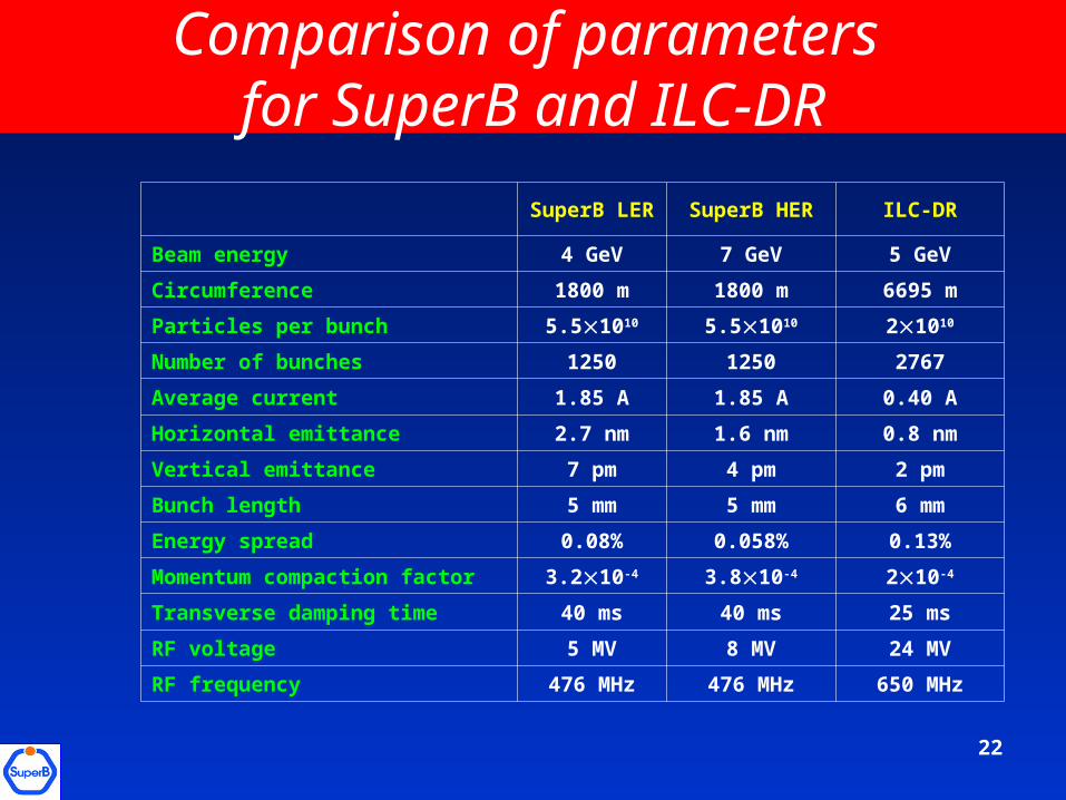
Comparison of parameters for SuperB and ILC-DR
SuperB LER SuperB HER ILC-DR
Beam energy 4 GeV 7 GeV 5 GeV
Circumference 1800 m 1800 m 6695 m
Particles per bunch 5.51010 5.51010 21010
Number of bunches 1250 1250 2767
Average current 1.85 A 1.85 A 0.40 A
Horizontal emittance 2.7 nm 1.6 nm 0.8 nm
Vertical emittance 7 pm 4 pm 2 pm
Bunch length 5 mm 5 mm 6 mm
Energy spread 0.08% 0.058% 0.13%
Momentum compaction factor 3.210-4 3.810-4 210-4
Transverse damping time 40 ms 40 ms 25 ms
RF voltage 5 MV 8 MV 24 MV
RF frequency 476 MHz 476 MHz 650 MHz
23
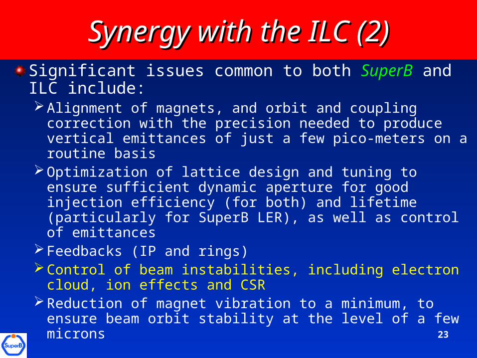
Significant issues common to both SuperB and ILC include:Alignment of magnets, and orbit and coupling correction
with the precision needed to produce vertical emittances of just a few pico-meters on a routine basis
Optimization of lattice design and tuning to ensure sufficient dynamic aperture for good injection efficiency (for both) and lifetime (particularly for SuperB LER), as well as control of emittances
Feedbacks (IP and rings)Control of beam instabilities, including electron cloud, ion
effects and CSRReduction of magnet vibration to a minimum, to ensure
beam orbit stability at the level of a few microns
Synergy with the ILC (2)Synergy with the ILC (2)
24
-600 -400 -200 0 200 400 600 800-500
-400
-300
-200
-100
0
ILC Damping Ring
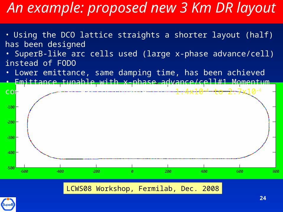
An example: proposed new 3 Km DR layout
• Using the DCO lattice straights a shorter layout (half) has been designed• SuperB-like arc cells used (large x-phase advance/cell) instead of FODO • Lower emittance, same damping time, has been achieved• Emittance tunable with x-phase advance/cell#1 Momentum compaction also easily tunable from 1.4x10⁻⁴ to 2.7x10⁻⁴
LCWS08 Workshop, Fermilab, Dec. 2008
25
All these issues are presently active areas of research and development for the ILCAdvantage could be taken whether the facilities are constructed and commissioned sequentially, or in parallel.In general, the similarity of the proposed operating regimes for the ILC-DR and SuperB presents an opportunity for a well-coordinated program of activities that could yield much greater benefits than would be achieved by separate, independent research and development programs
Synergy with the ILC (3)Synergy with the ILC (3)
26
A Conceptual Design Report has been published in May 2007 and positively reviewed by an International Review Committee, chaired by J. Dainton (UK)A Machine Advisory Committee, chaired by J. Dorfan (SLAC), has scrutinized the machine design in July 2008 endorsing the design approachThe next step will be to complete the Technical Design Report by 2010 (SuperB Workshop in Paris, Feb. 15-18, will be the starting time)Synergy with the ILC accelerator R&D are many. Collaboration started already on personal basis, it would be good to strenghten it with official commitments from both communities
ConclusionsConclusions