super retrograde - zimmer biomet · super retrograde nail ream first 6cm to 13mm diameter....
TRANSCRIPT

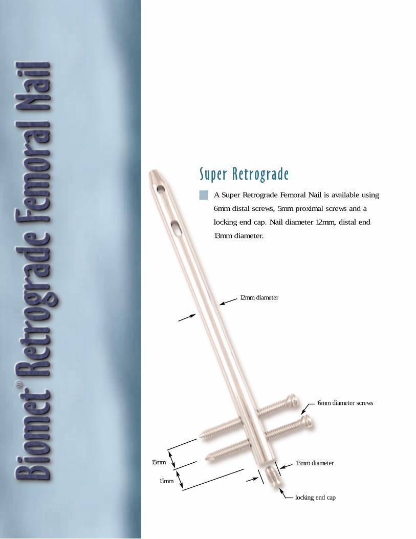
12mm diameter
13mm diameter
Super Retrograde
15mm
6mm diameter screws
locking end cap
15mm
A Super Retrograde Femoral Nail is available using
6mm distal screws, 5mm proximal screws and a
locking end cap. Nail diameter 12mm, distal end
13mm diameter.

15mm
15mm
10mm, 11mm and 12mm diameters
5mm diameter bolts
13mm diameter washers
locking T-nut
NOTE: Illustration shown using
nut, bolt and washers.
15mm
30mm
1
This brochure is presented to demonstrate the surgi-
cal technique utilized by J. Dean Cole, M.D., Orlando,
Florida. Biomet, as the manufacturer of this device,
does not practice medicine and does not recommend
this or any other surgical technique for use on a spe-
cific patient. The surgeon who performs any implant
procedure is responsible for determining and utilizing
the appropriate techniques for implanting the pros-
thesis in each individual patient. Biomet is not
responsible for selection of the appropriate surgical
technique to be utilized for an individual patient.
Anatomic Design, Optimal Patient Sizing
Proven clinical results.1–5
A/P proximal screw placement for ease of use with patient
positioning and intraoperative imaging.
The strength and biocompatibility of titanium alloy.
Fully cannulated, closed section nail design.
Anatomic design and uncompromising fit via a 5° anterior
bend and an anterior bow.
Optimal patient sizing 10, 11 and 12mm nail diameters,
nail lengths from 20–44cm.
The option of a nut/bolt and washer for distal fixation.
Fully threaded 5mm titanium screws.
Precise, reproducible instrumentation.
12mm diameter

Clinical management of supracondylar
fractures, especially those proximal
to a solidly-fixed femoral total knee
prosthesis, present the challenge of
providing adequate stability, often
with a compromised surgical approach.
The literature would suggest that alter-
natives to historic methods of open
reduction, pinning, and/or internal fixation
be selected as treatments of choice.
Indications may include: open and closed
acute distal femoral fractures, pathological
fractures, malunions, nonunions, osteo-
tomies, failed plate-screw osteosyntheses
of the distal femur, fractures proximal to a
total knee arthroplasty and fractures distal
to a total hip prosthesis.
The Biomet® Retrograde Femoral Nail
is anatomic and offers the advantages of
optimal patient sizing over short, straight
nail designs. Furthermore, its anterior-
posterior proximal screws promote
ease-of-use with desired patient positioning
and intraoperative imaging.
Supracondylar (Extraarticular)Fractures
Fractures Proximal to Total KneeArthroplasties
Fractures Distal to Total HipArthroplasties Intracondylar (Intraarticular) Fractures
2
Patient PositioningThe patient is placed in a supine position on a radiolucent
table. The limb is prepped and draped with a split drape in
a sterile fashion.
Flex the knee 90°– 120° (120° is recommended) over a
well padded thigh support to provide access for adequate
reduction and fixation. An assistant is needed to stabilize
reduction during canal preparation.
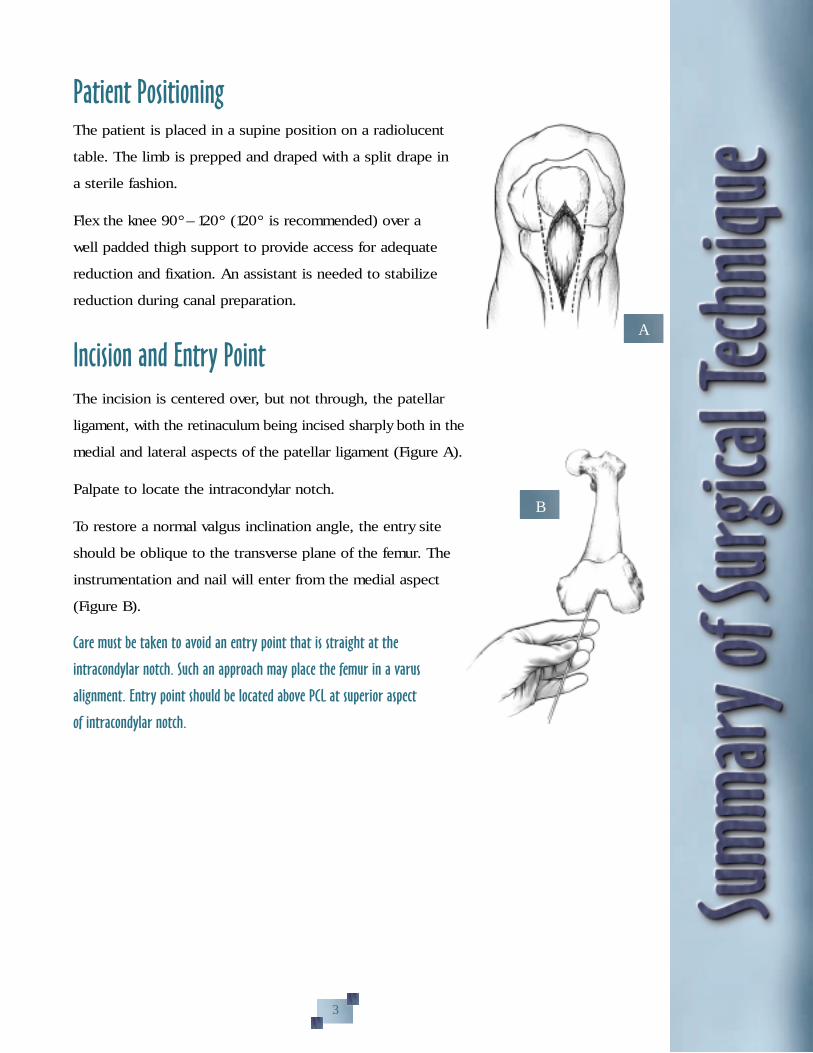
Incision and Entry PointThe incision is centered over, but not through, the patellar
ligament, with the retinaculum being incised sharply both in the
medial and lateral aspects of the patellar ligament (Figure A).
Palpate to locate the intracondylar notch.
To restore a normal valgus inclination angle, the entry site
should be oblique to the transverse plane of the femur. The
instrumentation and nail will enter from the medial aspect
(Figure B).
Care must be taken to avoid an entry point that is straight at the
intracondylar notch. Such an approach may place the femur in a varus
alignment. Entry point should be located above PCL at superior aspect
of intracondylar notch.
A
B
3
D
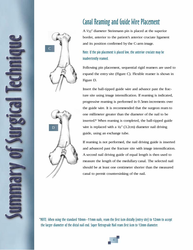
Canal Reaming and Guide Wire PlacementA 5/32" diameter Steinmann pin is placed at the superior
border, anterior to the patient’s anterior cruciate ligament
and its position confirmed by the C-arm image.
Note: If the pin placement is placed low, the anterior cruciate may be
inadvertently reamed.
Following pin placement, sequential rigid reamers are used to
expand the entry site (Figure C). Flexible reamer is shown in
Figure D.
Insert the ball-tipped guide wire and advance past the frac-
ture site using image intensification. If reaming is indicated,
progressive reaming is performed in 0.5mm increments over
the guide wire. It is recommended that the surgeon ream to
one millimeter greater than the diameter of the nail to be
inserted.* When reaming is completed, the ball-tipped guide
wire is replaced with a 1/8" (3.2cm) diameter nail driving
guide, using an exchange tube.
If reaming is not performed, the nail driving guide is inserted
and advanced past the fracture site with image intensification.
A second nail driving guide of equal length is then used to
measure the length of the medullary canal. The selected nail
should be at least one centimeter shorter than the measured
canal to permit countersinking of the nail.
C
4
*NOTE: When using the standard 10mm–11mm nails, ream the first 6cm distally (entry site) to 12mm to accept
the larger diameter of the distal nail end. Super Retrograde Nail ream first 6cm to 13mm diameter.
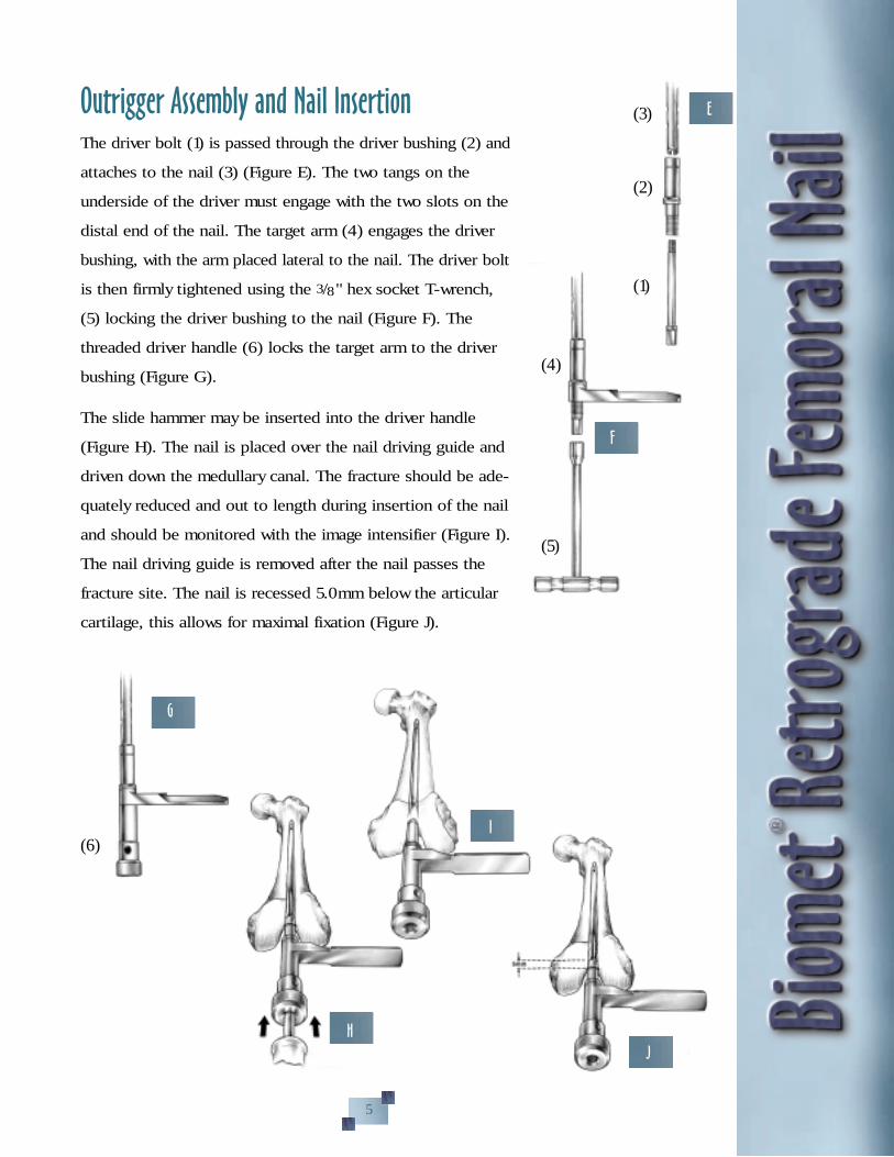
Outrigger Assembly and Nail InsertionThe driver bolt (1) is passed through the driver bushing (2) and
attaches to the nail (3) (Figure E). The two tangs on the
underside of the driver must engage with the two slots on the
distal end of the nail. The target arm (4) engages the driver
bushing, with the arm placed lateral to the nail. The driver bolt
is then firmly tightened using the 3/8" hex socket T-wrench,
(5) locking the driver bushing to the nail (Figure F). The
threaded driver handle (6) locks the target arm to the driver
bushing (Figure G).
The slide hammer may be inserted into the driver handle
(Figure H). The nail is placed over the nail driving guide and
driven down the medullary canal. The fracture should be ade-
quately reduced and out to length during insertion of the nail
and should be monitored with the image intensifier (Figure I).
The nail driving guide is removed after the nail passes the
fracture site. The nail is recessed 5.0mm below the articular
cartilage, this allows for maximal fixation (Figure J).
F
G
I
J
E
H
(3)
(2)
(1)
(4)
(5)
(6)
5
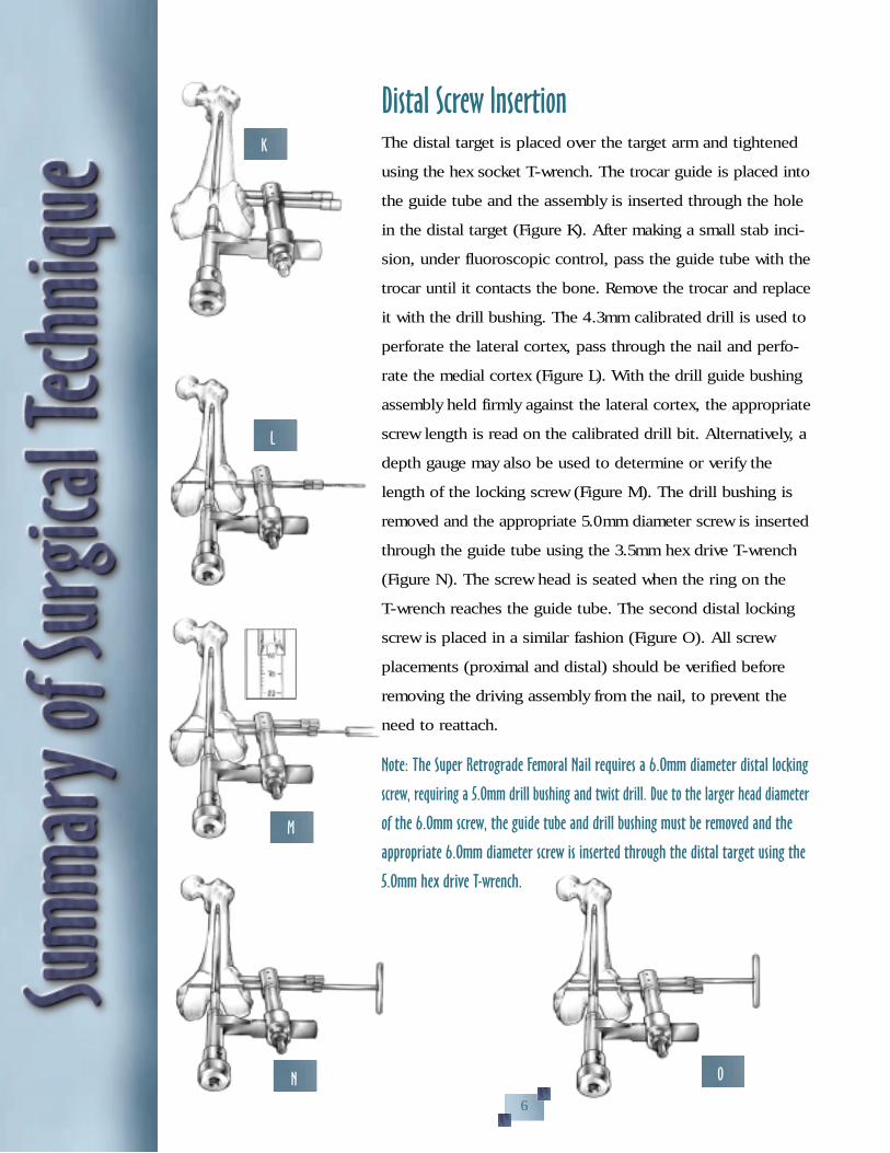
Distal Screw InsertionThe distal target is placed over the target arm and tightened
using the hex socket T-wrench. The trocar guide is placed into
the guide tube and the assembly is inserted through the hole
in the distal target (Figure K). After making a small stab inci-
sion, under fluoroscopic control, pass the guide tube with the
trocar until it contacts the bone. Remove the trocar and replace
it with the drill bushing. The 4.3mm calibrated drill is used to
perforate the lateral cortex, pass through the nail and perfo-
rate the medial cortex (Figure L). With the drill guide bushing
assembly held firmly against the lateral cortex, the appropriate
screw length is read on the calibrated drill bit. Alternatively, a
depth gauge may also be used to determine or verify the
length of the locking screw (Figure M). The drill bushing is
removed and the appropriate 5.0mm diameter screw is inserted
through the guide tube using the 3.5mm hex drive T-wrench
(Figure N). The screw head is seated when the ring on the
T-wrench reaches the guide tube. The second distal locking
screw is placed in a similar fashion (Figure O). All screw
placements (proximal and distal) should be verified before
removing the driving assembly from the nail, to prevent the
need to reattach.
Note: The Super Retrograde Femoral Nail requires a 6.Omm diameter distal locking
screw, requiring a 5.Omm drill bushing and twist drill. Due to the larger head diameter
of the 6.Omm screw, the guide tube and drill bushing must be removed and the
appropriate 6.Omm diameter screw is inserted through the distal target using the
5.Omm hex drive T-wrench.
K
L
M
N O
6

Distal Screw Insertion Using the Nut/Bolt and WasherThe instruments are assembled in the usual manor as used
with the fully threaded screw. A new 5.0mm drill bushing is
used to receive the 5.0mm drill. After making a small stab
incision, under fluoroscopic control, the 5.0mm drill is used
to perforate the lateral cortex, pass through the nail and per-
forate the medial cortex. Remove the 5.0mm drill.
Place the calibrated alignment guide through the 5.0mm drill
bushing, lateral cortex, nail, and into the medial cortex. Make
a small stab incision on the medial side under fluoroscopic
control over the end of the protruding alignment guide. The
cannulated reamer with stop is placed over the end of the
alignment guide (Figure P). The medial side is reamed
to the depth stop on the reamer to receive the T-nut. The
alignment guide will be pushed to the lateral side during the
reaming process. It is important to use the alignment guide
with the reamer for proper alignment of the T-nut and bolt.
Remove the cannulated reamer with stop.
With the calibrated alignment guide in place and the end
protruding on the medial side, the T-nut and washer is placed
over the end of the alignment guide and seated by using the
3.5mm hex T-wrench. This is achieved by pushing on the
T-wrench (Figure Q).
P
Q
7

With the T-nut and washer fully seated, the bolt length can be
determined by reading the calibrations on the lateral side of
the calibrated alignment guide, at the
bone interface. Calibrations allow for
10.0mm initial engagement of thread
and 15.0mm of compression.* To read
the calibrations, move the distal target
away from the femur (Figure R). After
selecting the correct bolt length, remove
the alignment guide, along with the distal
target, guide tube and drill bushing.
Insert the bolt and washer through the lateral cortex, pass
through the nail and turn into the T-nut using the 3.5mm hex
T-wrench on both the lateral and medial sides (Figure S).
THE BOLT AND WASHER WILL NOT PASS THROUGH THE
DISTAL TARGET AND SHOULD BE REMOVED. Repeat
steps for second nut/bolt (Figure T).
*Note: Length range of 5.Omm diameter bolt with T-nut is as follows.
Bolt Length Range
50mm 50–65mm
60mm 60–75mm
70mm 70–85mm
80mm 80–95mm
S
T
8
R

Proximal Screw Insertion Using the Freehand Technique
The image intensifier is positioned about the proximal femur
such that either of the proximal screw holes appears as a
circle in the center of the viewing screen. A pointed awl or
Steinmann pin is placed on the skin anteriorly, with the tip
centered on the screw hole, as seen on the image intensifier
(Figure U). A 3–4cm incision is made and a blunt dissection
is carried to the anterior cortex. The drill, with guide tube, is
placed on the bone with the point centered within the screw
hole, as seen on the image intensifier. The 4.3mm diameter
drill with stop is brought in line with the axis of the beam
and drilled through the anterior cortex, nail and posterior
cortex. The position of the 4.3mm diameter drill should be
confirmed with the image intensifier before it is withdrawn.
Note: Anatomic structures to consider on proximal locking include the femoral
artery (medial side) and/or the sciatic nerve (posterior side).
An alternate technique for placing the proxi-
mal screws is using the Biomet® Radiolucent
Targeting Device (Figure V).
Screw Length/InsertionThe length of the screw is measured with the depth gauge
and an appropriate 5.0mm diameter screw is inserted, using a
Williams self-holding screwdriver (Figure W).
U
W
9
Biomet® Radiolucent Targeting Device
V
X
End Cap Placement After the driver assembly is removed, an end cap is inserted
into the end of the nail using the hex-drive T-wrench. As an
alternative, the locking end cap, which engages the most
distal screw, may be used.
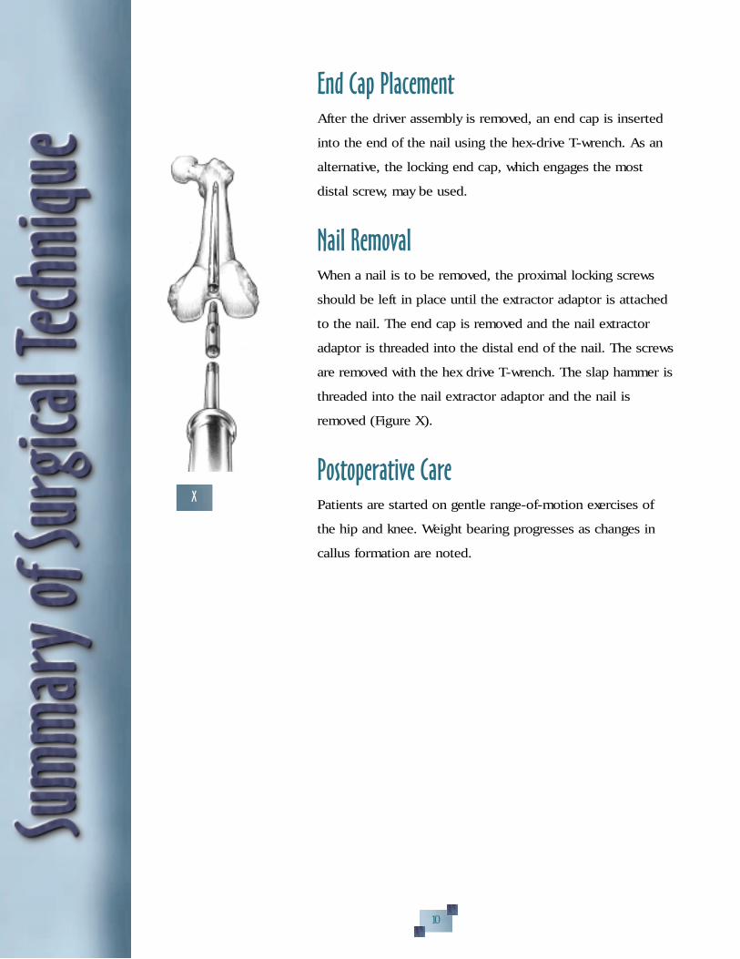
Nail RemovalWhen a nail is to be removed, the proximal locking screws
should be left in place until the extractor adaptor is attached
to the nail. The end cap is removed and the nail extractor
adaptor is threaded into the distal end of the nail. The screws
are removed with the hex drive T-wrench. The slap hammer is
threaded into the nail extractor adaptor and the nail is
removed (Figure X).
Postoperative CarePatients are started on gentle range-of-motion exercises of
the hip and knee. Weight bearing progresses as changes in
callus formation are noted.
10

Titanium Retrograde Femoral NailPart Number
Length
20cm24cm28cm32cm34cm36cm38cm40cm44cm
10mmDiameter
343520343524343528343532343534343536343538343540343544
11mmDiameter
343620343624343628343632343634343636343638343640343644
12mmDiameter
343720343724343728343732343734343736343738343740343744
Titanium Nut/Bolt/WasherPart Number
33-34546033-34546233-34546433-34546633-345472
245890
Description
5 x 50–65mm Bolt5 x 60–75mm Bolt5 x 70–85mm Bolt5 x 80–95mm BoltLocking T-Nut 5mm
Titanium Washer 13mm
Ti-Screw Buttress Thread5mm DiameterFully Threaded
Part Number
33-34542033-34542233-34542433-34542633-34542833-34543033-34543233-34543433-34543633-34543833-34544033-34544233-34544433-34544633-34544833-345450
Length
25mm30mm35mm40mm45mm50mm55mm60mm65mm70mm75mm80mm85mm90mm95mm100mm
Titanium End Cap345220
Titanium Fixation screws usea 3.5mm hex drive wrench
Titanium Super RetrogradeFemoral Nail
Distal End 13mmPart Number
12mm diameter
344920344924344928344932344934344936344938344940344944
Length
20cm24cm28cm32cm34cm36cm38cm40cm44cm
Titanium Locking End Cap345216
Ti-Screw Buttress Thread6mm DiameterFully Threaded
Part Number
345532345534345536345538345540345542345544345546345548
Length
60mm65mm70mm75mm80mm85mm90mm95mm100mm
Above nails use a 6.0mm diameterscrew distally and a 5.0mm diam-eter screw proximally
6mm screws used only on distalholes of Super Retrograde FemoralNail, uses a 5.0mm hex drivewrench.
Uses 3.5mm hex drive wrench.
NOTE: The locking end cap number 345216
designed for the Super Retrograde Femoral Nail can
also be used to lock the most distal screw in the
standard 10, 11 and 12mm diameters Retrograde
Femoral Nail.
11
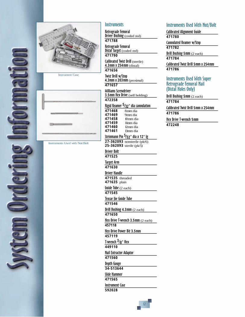
Instruments
Retrograde FemoralDriver Bushing (coded red)471788
Retrograde FemoralDistal Target (coded red)471790
Calibrated Twist Drill (sterile)4.3mm x 254mm (distal)471656
Twist Drill w/Stop4.3mm x 203mm (proximal)471657
Williams Screwdriver3.5mm Hex Drive (self holding)472358
Rigid Reamer 5/32" dia cannulation471468 8mm dia471469 9mm dia471458 10mm dia471459 11mm dia471460 12mm dia471461 13mm dia
Steinmann Pin 5/32" dia x 12" lg27-362093 nonsterile (pk/6)25-362093 sterile (pk/5)
Driver Bolt471525
Target Arm471630
Driver Handle 471535 threaded471635 plain
Guide Tube (2 each)471545
Trocar for Guide Tube471546
Drill Bushing 4.3mm (2 each)471650
Hex Drive T-wrench 3.5mm (2 each)457118
Hex Drive Power Bit 3.5mm457119
T-wrench 3/8" Hex449110
Nail Extractor Adaptor471560
Depth Gauge34-513644
Slide Hammer471565
Instrument Case592028
Instruments Used With Nut/Bolt
Calibrated Alignment Guide471780
Cannulated Reamer w/Stop471782
Drill Bushing 5mm (2 each)471784
Calibrated Twist Drill 5mm x 254mm471786
Instruments Used With SuperRetrograde Femoral Nail(Distal Holes Only)
Drill Bushing 5mm (2 each)
471784
Calibrated Twist Drill 5mm x 254mm
471786
Hex Drive T-wrench 5mm
472248
Instrument Case
Instruments Used with Nut/Bolt
12

Modular Flexible Reamer System
Reamer Reamer HeadsHeads Ti-Nitrited
467734 8.0mm 467634467736 8.5mm 467636467738 9.0mm 467638467740 9.5mm 467640467742 10.0mm 467642467744 10.5mm 467644467746 11.0mm 467646467748 11.5mm 467648467750 12.0mm 467650467752 12.5mm 467652467754 13.0mm 467654467756 13.5mm 467656467758 14.0mm 467658467760 14.5mm 467660467762 15.0mm 467662467764 15.5mm 467664467766 16.0mm 467666467768 16.5mm 467668467770 17.0mm 467670467772 17.5mm 467672467774 18.0mm 467674467776 18.5mm 467676467778 19.0mm 467678467780 19.5mm 467680467782 20.0mm 467682
Reamer Shafts
467716 8.0mm Dia. 40cm Length467718 8.0mm Dia. 52cm Length
Sterilization Case
593243
Suggested AdditionalInstrumentation
Guide Pin Handgrip469675
Telescoping Nail Measuring Gauge469380
Ball Tip Guide 3.2mm x 98cm469060
Medullary Alignment Tube w/Ring 8mm
469388 (pk/6)469389 (ea)
Medullary Alignment Tube w/o Ring 8mm 469392 (pk/6)469393 (ea)
Skin Protector
476920
Reduction Lever
469385
Canal Sizer—Cannulated469310 10mm469311 11mm469312 12mm
Distal Target Awl 4.3mm471794
X-ray Scale475920
Nail Driving Guide 3.2mm x 80cm (2 each)467210
Radiolucent Distal Targeting Device471830 Device471845 4.3mm drill bit w/stop
13
Biomet® is a registered trademark of Biomet, Inc.1 Ostrum RF and, Poka A; “Ipsilateral Femoral Hip and Shaft Fractures: A Management Protocol.” A Supp. to Am. J. of
Orthopedics, IS:4–11, 1999.2 Morgan E, Ostrum RF, DiCicco J, McElroy J and Poka A; “Effects of Retrograde Femoral Intramedullary Nailing on the
Patellofemoral Articulation.” J. Orthop Trauma, 1:13–16, 1999.3 Ostrum RF, DiCicco J, Lakatos and Poka A; “Retrograde Intramedullary Nailing of Femoral Diaphyseal Fractures.”
J. Orthop. Trauma, 7:464–468, 1998.4 Ryan MG, Khan AM and Meinhard BP; “Distal Femur Fractures and Retrograde Intramedullary Rod Fixation.” A Supp. to
Am J. Orthopedics, 2S:46–50, 1998.5 Cole JD, Huff WA and Blum DA; “Retrograde Femoral Nailing of Supracondylar, Intercondylar and Distal Fractures of the
Femur.” A Supp. to Am. J. Orthopedics, 5S:22–30, 1998.

P.O. Box 587, Warsaw, IN 46581-0587 • 219.267.6639 • ©1999 Biomet, Inc. All Rights Reservedweb site: http://www.biomet.com • eMail: [email protected]
Form No. Y-BMT-568R/113099/K