submodeling automation in ansys workbench mechanical · pdf fileansys workbench mechanical. 2...
TRANSCRIPT
© 2012 CAE Associates
SubmodelingAutomation in
Ansys Workbench Mechanical
2
Submodeling - Background
l Submodeling is an analysis technique that allows for a more refined solution to be calculated from a previous analysis.
— This analysis technique uses two separate models (one coarse and one more refined).
— The results from the coarse model are mapped onto the refined model as an analysis input.
l The results that are typically mapped between the two different models are displacements.
— i.e. the calculated displacement results from the coarse model are mapped as input displacements onto the refined model.
l Displacements or forces could however be used with this technique.
3
Submodeling - Background
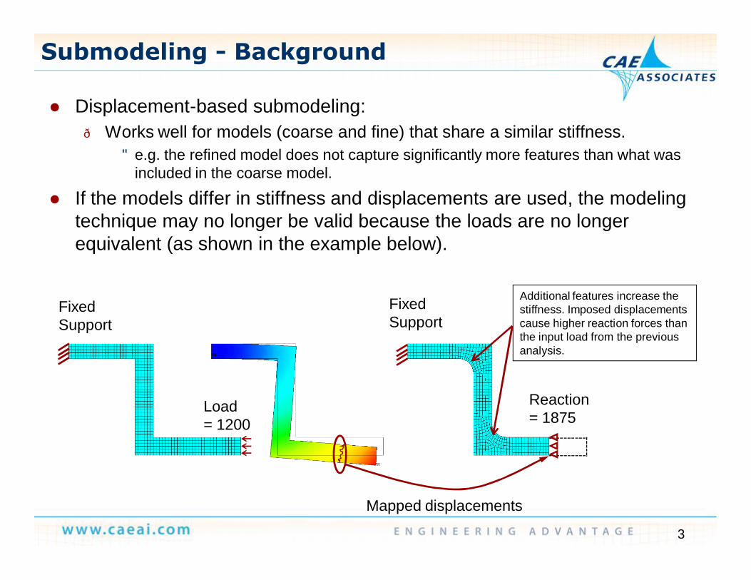
l Displacement-based submodeling:— Works well for models (coarse and fine) that share a similar stiffness.
• e.g. the refined model does not capture significantly more features than what was included in the coarse model.
l If the models differ in stiffness and displacements are used, the modeling technique may no longer be valid because the loads are no longer equivalent (as shown in the example below).
Load = 1200
Reaction = 1875
Fixed Support
Fixed Support
Mapped displacements
Additional features increase the stiffness. Imposed displacements cause higher reaction forces than the input load from the previous analysis.

4
Submodeling - Background
l Force-based submodeling:— Useful when the refined model does not match up well with the global model’s
stiffness.— Using forces allows for both models to share the same loading.
l An example of using forces is shown below:
Load = 1200
Fixed Support
Fixed Support
Mapped forces
Same load transferred between the two models when mapping forces.
Load = 1200

5
Submodeling - Background
l Displacement-based submodeling:— This procedure is already built within MAPDL.— This type of submodeling can be done within Workbench; however it would
require either a series of command blocks and/or using the external data feature to perform the mapping.
l Force-based submodeling:— This is not directly available within either the MAPDL or Workbench GUIs.— How this technique was implemented within Workbench will be shown.

6
Workbench Submodel Automation
l Procedure Summary— Run global model, possibly many load cases.— Apply global model cut boundary loads on submodel.
l Workbench Mechanical automation procedure for detailed analysis:
Global model with loads to… Submodel with applied freebodyloads from the Global model

7
Workbench Submodel Automation
l Summary of the overall approach: Apply the global model load set to a refined-mesh model in Mechanical.
l Loads are applied using a “Remote Force and/or Remote Moment” which is connected to a surface via MPC type formulation.
— This is a force-distributed formulation that does not impart any additional stiffness.
— Rigid-distributed formulation can be used if desired.l The location of each remote point is automatically
obtained from the GRID coordinates in the global model load file.
l The surface to which the loads are applied is set up by the user as a “Named Selection” in Mechanical.

8
Workbench Submodel Automation
l What does the user have to do?— Create the global model loads file, formatted as shown:
• Note: Exclude the header line, shown for format purposes only.
— The following MAPDL script can be used as an example to generate this file:
Node Number Node X – Coord Node Y - Coord Node Z – Coord X – Force Y – Force Z – Force X - Moment Y – Moment Z - Moment0.34600000E+03 0.22869699E+01 0.39693382E+01 0.10000000E+01 -0.43632647E+03 0.00000000E+00 -0.10134672E+03 0.00000000E+00 0.00000000E+00 0.00000000E+000.34700000E+03 0.20547679E+01 0.41314414E+01 0.10000000E+01 0.44097543E+02 0.00000000E+00 -0.24463717E+02 0.00000000E+00 0.00000000E+00 0.00000000E+000.34800000E+03 0.18225660E+01 0.42935446E+01 0.10000000E+01 -0.67849514E+02 0.00000000E+00 0.11068292E+02 0.00000000E+00 0.00000000E+00 0.00000000E+000.34900000E+03 0.15903641E+01 0.44556478E+01 0.10000000E+01 -0.41197611E+03 0.00000000E+00 0.14319679E+02 0.00000000E+00 0.00000000E+00 0.00000000E+000.35000000E+03 0.13581622E+01 0.46177510E+01 0.10000000E+01 -0.32768655E+03 0.00000000E+00 0.47461539E+02 0.00000000E+00 0.00000000E+00 0.00000000E+000.36200000E+03 -0.11653908E+01 0.41971589E+01 0.10000000E+01 -0.25396659E+03 0.24740064E+03 0.00000000E+00 0.00000000E+00 0.00000000E+00 0.00000000E+000.36300000E+03 -0.13489603E+01 0.40477800E+01 0.10000000E+01 -0.41577343E+03 0.57856992E+03 0.00000000E+00 0.00000000E+00 0.00000000E+00 0.00000000E+000.36400000E+03 -0.15325299E+01 0.38984010E+01 0.10000000E+01 -0.27608402E+03 0.40337368E+03 0.00000000E+00 0.00000000E+00 0.00000000E+00 0.00000000E+00
set,lastnsel,,,,Cut_Surfesel,,,,Cut_Body*dim,rxns,,ndinqr(0,13),7ndcur=0*do,i,1,ndinqr(0,13)ndcur=ndnext(ndcur)nsel,,,,ndcurFsumrxns(i,1)=ndcur*get,rxns(i,2),node,ndcur,loc,x*get,rxns(i,3),node,ndcur,loc,y*get,rxns(i,4),node,ndcur,loc,z*get,rxns(i,5),fsum,,ITEM,fx*get,rxns(i,6),fsum,,ITEM,fy*get,rxns(i,7),fsum,,ITEM,fznsel,,,,cut_Surf*enddo*mwrite,rxns,ANSYS_RXNs,csv,,jik(7E16.8)
9
Workbench Submodel Automation
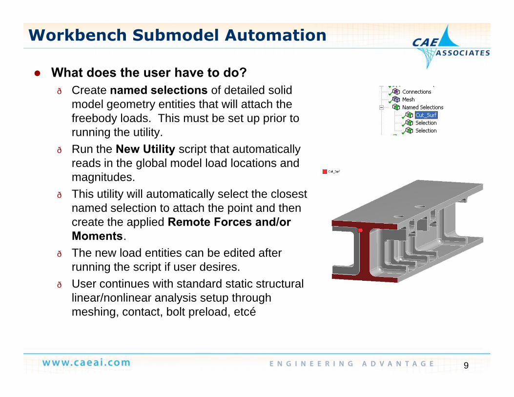
l What does the user have to do?— Create named selections of detailed solid
model geometry entities that will attach the freebody loads. This must be set up prior to running the utility.
— Run the New Utility script that automatically reads in the global model load locations and magnitudes.
— This utility will automatically select the closest named selection to attach the point and then create the applied Remote Forces and/or Moments.
— The new load entities can be edited after running the script if user desires.
— User continues with standard static structural linear/nonlinear analysis setup through meshing, contact, bolt preload, etc…

10
Workbench Submodel Automation
l Automated loads generation example:
11
Workbench Submodel Automation
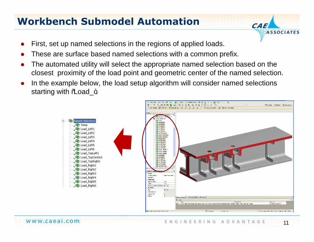
l First, set up named selections in the regions of applied loads.l These are surface based named selections with a common prefix.l The automated utility will select the appropriate named selection based on the
closest proximity of the load point and geometric center of the named selection.l In the example below, the load setup algorithm will consider named selections
starting with “Load_”.

12
Workbench Submodel Automation
l Next, launch the load setup utility from the new icon on the Tools menu.
13
Workbench Submodel Automation
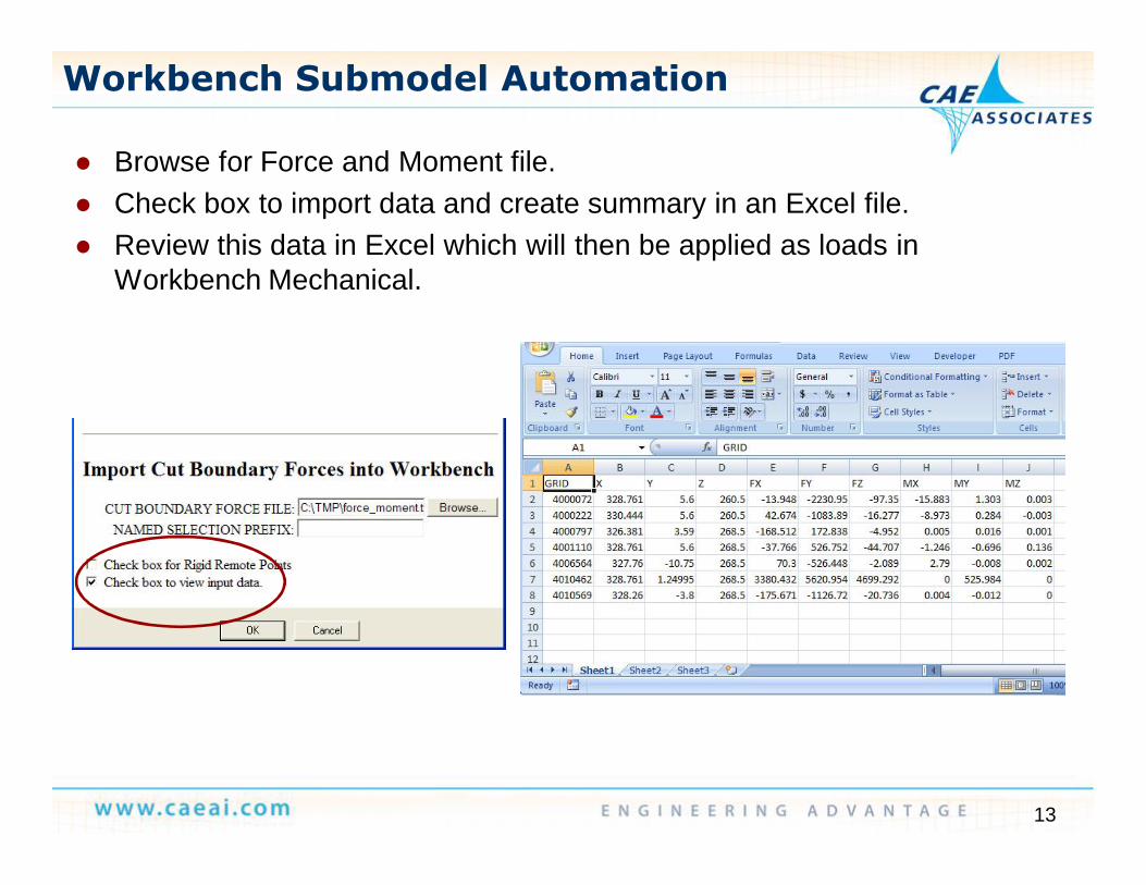
l Browse for Force and Moment file.l Check box to import data and create summary in an Excel file.l Review this data in Excel which will then be applied as loads in
Workbench Mechanical.
14
Workbench Submodel Automation
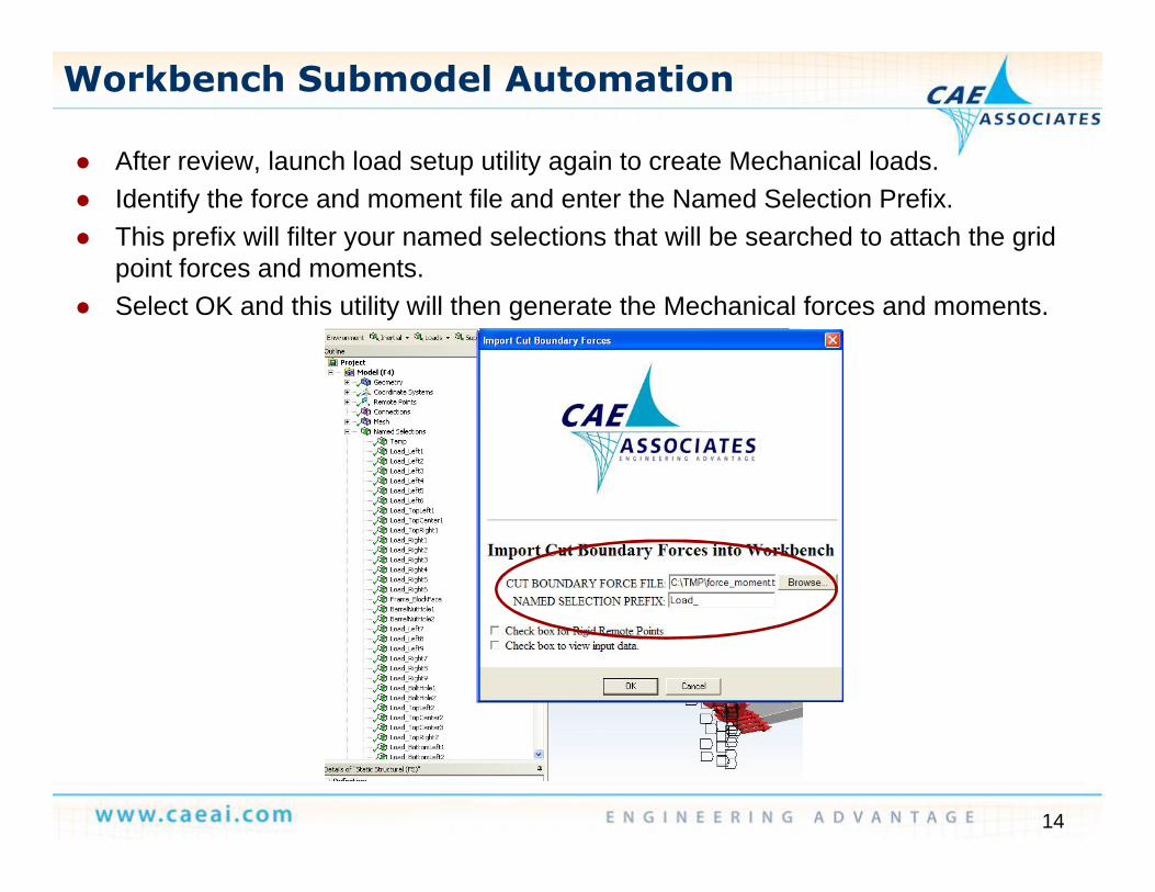
l After review, launch load setup utility again to create Mechanical loads.l Identify the force and moment file and enter the Named Selection Prefix.l This prefix will filter your named selections that will be searched to attach the grid
point forces and moments.l Select OK and this utility will then generate the Mechanical forces and moments.

15
Workbench Submodel Automation
l Now, review and modify any loads you may want to change.— The name of the applied Remote Force or Moment will correspond to the node
number from the force and moment file that was read in.

16
Workbench Submodel Automation
l Continue with structural analysis setup, solution, and postprocess.
17
Workbench Submodel Automation
Thank You!