subject code-421 semester-5 - madin poly · single cylinder four stroke petrol engine test rig with...
TRANSCRIPT
HEATE ENGINE LAB
SUBJECT CODE-421
SEMESTER-5
SINGLE CYLINDER FOUR STROKE PETROL ENGINE TEST RIG
WITH ROPE BRAKE DYNAMOMETER
AIM:
To conduct a performance test on single cylinder four stroke petrol engine.
DESCRIPTION:
The Rope brake Dynamometer is coupled to the Engine and the engine is
mounted on a MS. Channel Frame. Panel board is used to fix burette with 3-way
cock, digital temperature indicator with selector, Digital Speed indicator and
’U’ tube manometer.
INSTRUMENTATION:
1. Digital Temperature Indicator to measure different temperature sensed by
respective thermocouples.
2. Manometer to measure the quantity of air drawn into the engine cylinder.
3. Burette to measure the rate of fuel consumed.
4. Digital speed indicator to measure the speed of the engine.
ENGINE SPECIFICATION:
MAKE : HONDA
BHP : 3
SPEED : 3000RPM
NO. OF CYLINDER : ONE
BORE : 67mm
STROKE : 56mm
ORIFICE DIA : 20mm
TYPE OF IGNITION : SPARK IGNITION
METHOD OF LOADING : ROPE BRAKE DYNAMOMETER
METHOD OF STARTING : ROPE
METHOD OF COOLING : AIR COOLED
TO DETERMINE THE FOLLOWING:
1. Specific Fuel Consumption : SFC
2. Brake Horse Power : BP
3. Brake Thermal Efficiency : ηBth
4. Volumetric Efficiency : ηVol
The engine test rig is directly coupled to a brake drum through a shaft and
a rope is wound around the drum. One end of the rope is connected to a
balance and the other end to a linear balance. The load to the engine can
be varied by rotating the hand wheel. Allow cooling water to the brake
drum while applying the load.
H.P = (2πNT/4500) x 0.75Kw
T = Torque = W x Re
Where,
W = Net load applied in Kgs = w1 – w2
W1 = Dial balance reading in Kgs
W2 = Linear Balance reading in kgs (pocket type)
Re = Effective radius of the brake drum = D+d /2 = 0.115m
D = Diameter of the brake drum = 0.217m
D = Diameter of the rope in m (0.015m)
N = Speed of engine
FUEL MEASUREMENT
The fuel is supplied from the main fuel tank through a measuring burette
with 3 way manifold system. To measure the fuel consumption of the
engine, fill the burette by opening the cock from the tank. When the
burette is filled with fuel, close the cock from tank. By starting a stop
clock measure the time taken to consume 10cc of fuel.
Weight of fuel, wf = (10/Time) x (Specific gravity of diesel / 1000) x
3600 kg/hr
AIR FLOW MEASURMENT:
An air drum is fitted on the panel frame and is connected to the engine
through an air hose. The air drum facilitates an orifice. The pressure
pickup point is connected to ‘U’ tube manometer limb. The difference in
manometer reading is taken at different loads and the air sucked by the
engine is calculated by
Va = Cd Ao �2�ℎ� �ρ�ρ x 3600
m3/hr
Where,
Ao = Area of orifice = πd2/4 m
2
Cd of orifice = 0.62
Dia of orifice, d = 20mm
TEMPERATURE MEASUREMENT
A digital temperature indicator with selector switch is provided on the
panel to read the temperature in deg.c, directly sensed by thermocouples
located at different places on the engine test rig.
T1 = Exhaust gas temperature.
T2 = Temperature of air passing through engine head.
T3 = Room temperature.
DIGITAL SPEED INDICATOR
A Digital Speed indicator is provided with proximity sensor to measure
the speed of the engine (Readable only when the dynamometer is
coupled).
PROCEDURE
1. Connect the instruments power input plug to a 230V, single phase
power source. Now the digital temperature indicator displays the
respective readings.
2. Fill up the petrol into the tank.
3. Check the lubricating oil level in the sump.
4. Open the petrol cock provided underneath the petrol tank and. Also
ensure the accelerator knob is in cut off position (idle condition).
5. Start the engine by pulling. Now the engine is running at idling
speed.
6. Increase the speed by turning the accelerator knob clockwise until
the speed reaches approx. 3000RPM.
7. Now apply the load by rotating the hand wheel of rope brake
dynamometer. The load w1 is indicated on a dial type spring
balance in terms of kg and w2 is linear balance reading. Net load
W = W1-W2. Now the engine speed decreases due to the
application of load. Operate the acceleration knob simultaneously
with the rope brake dynamometer hand wheel and set the load to ¼
of the full load ie, 5kg (approx) on the spring balance.
8. Allow the engine to run at the set load and speed for few minutes.
Note down the readings. Then increase the load by repeating the
same procedure up to maximum load ie 6.2kg.
FORMULAE REQUIRED
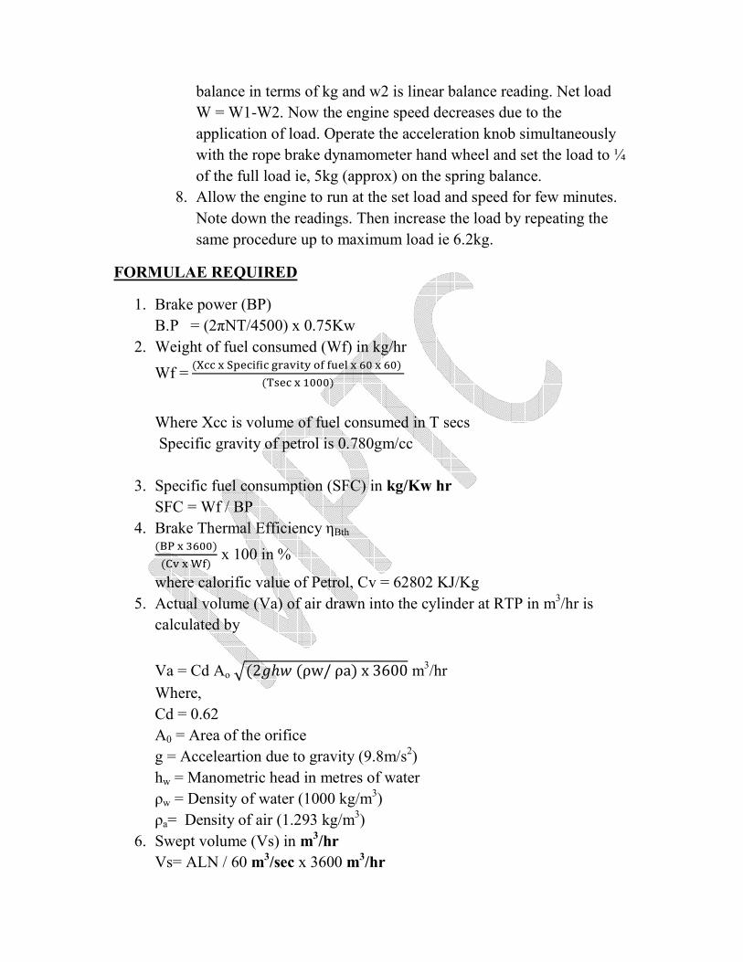
1. Brake power (BP)
B.P = (2πNT/4500) x 0.75Kw
2. Weight of fuel consumed (Wf) in kg/hr
Wf = (��� � �������� ������ �� ��� � !" � !") ($%�� � &""")
Where Xcc is volume of fuel consumed in T secs
Specific gravity of petrol is 0.780gm/cc
3. Specific fuel consumption (SFC) in kg/Kw hr
SFC = Wf / BP
4. Brake Thermal Efficiency ηBth ('( � )!"")(*� � +�) x 100 in %
where calorific value of Petrol, Cv = 62802 KJ/Kg
5. Actual volume (Va) of air drawn into the cylinder at RTP in m3/hr is
calculated by
Va = Cd Ao ,(2�ℎ� (ρw/ ρa) x 3600 m3/hr
Where,
Cd = 0.62
A0 = Area of the orifice
g = Acceleartion due to gravity (9.8m/s2)
hw = Manometric head in metres of water
ρw = Density of water (1000 kg/m3)
ρa= Density of air (1.293 kg/m3)
6. Swept volume (Vs) in m3/hr
Vs= ALN / 60 m3/sec x 3600 m
3/hr
7. Where, A = Area of cylinder
L = Stroke length
N = Speed of the engine
8. Volumetric efficiency η vol
(Actual Volume / Swept Volume) x 100 in %
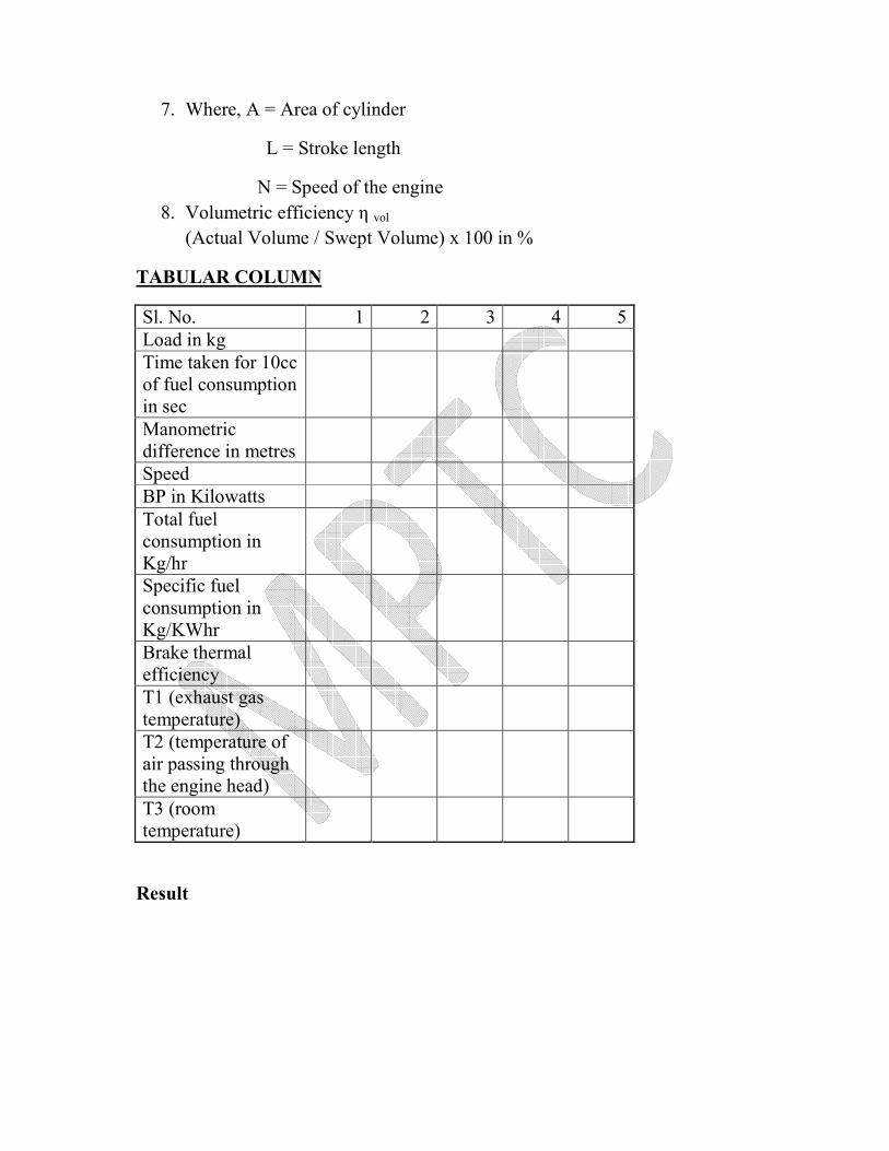
TABULAR COLUMN
Sl. No. 1 2 3 4 5
Load in kg
Time taken for 10cc
of fuel consumption
in sec
Manometric
difference in metres
Speed
BP in Kilowatts
Total fuel
consumption in
Kg/hr
Specific fuel
consumption in
Kg/KWhr
Brake thermal
efficiency
T1 (exhaust gas
temperature)
T2 (temperature of
air passing through
the engine head)
T3 (room
temperature)
Result
PENSKY MARTEN CLOSED CUP FLASH POINT
APPARATUS
Aim :
To determine the flash & Fire point of the given oil by using
close cup apparatus.
Apparatus required :
Pensky marten close cup apparatus
Thermometer
Electric heater
Flash point :
Flash point of a material is the lowest temperature at which the
vapour of substance momentarily takes fire in the form of a flash
under specified condition of test.
Fire point :
The fire point is the lowest temperature at which the material gets
ignited and burns under specified condition of test. Generally this
event takes place 10º-15ºC above the flash point.
Procedure :
1. Clean the oil cup and take the given sample of oil up to the mark
and place the thermometer in the required position.
2. The bitumen sample is then heated.
3. Stirring is done at the rate of approximately 60 rev per minute
4. The test flame is applied at intervals depending upon expected
flash and fire points. Preferably 17ºC below the actual flash
point and then at every 1ºC to 3ºC.
5. The flash point is taken as the temperature read on the
thermometer at the time of the flame application that causes a
bright flash in the interior of the cup in closed system.(for open
cup it is the instance when flash appears first at any point on the
surface of the material)
6. Heating is continued until the volatiles ignite and the material
continues to burn for 5 seconds.
7. The temperature of the sample material when this occurs is
recorded as the fire point.
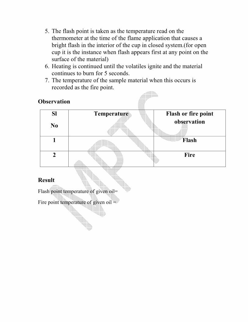
Observation
Sl
No
Temperature Flash or fire point
observation
1 Flash
2 Fire
Result
Flash point temperature of given oil=
Fire point temperature of given oil =
SINGLE CYLINDER AIR COMPRESSOR TEST RIG
Aim:
To conduct a test on single cylinder, single stage air compressor and to
determine the mechanical efficiency and isothermal efficiency at various
delivery pressure.
Description:
Single cylinder compressor is a reciprocating type driven by a prime mover AC
motor through belt. The test rig consists of a base on which the tank (air
reservoir) is mounted. The outlet of the air compressor is indicated by a pressure
gauge. The electrical safety valve is provided for an additional safety. The
suction is connected to the air tank with a calibrated orifice plate through the
water manometer. The input to the motor is recorded by an energy meter.
Procedure:
• Close the outlet valve
• Check the manometer connections. The manometer is filled with water up
to the half level.
• Start the compressor & wait till the pressure reaches 2kgs.
• The tank pressure gauge is read for a particular pressure.
• Note down the rpm of the compressor
• Note down the manometer reading
• Reading of energy meter
• Repeat the experiment for various pressure like 2,4,6,8,10 kgs
Calculations:
01. HNTP = hm=ha (ρw/ρa)
ρw = Density of water = 1000 kg/m3
ρa = Density of air = 1.293 kg/m3
h = Manometer reading in mm
02. Density of air at R.T.P
Air density at R.T.P = (ρa x 273)/ (273+ room temp.) kg/m3
03. Actual volume of air drawn at RTP condition
Va = Cd x A x 2gh (ρw/ρa) m3 /sec
Where Cd coefficient of discharge = 0.62
Area of orifice = πd2/4 in m
2
d = dia of orifice = 15mm (0.15m)
h = ha (ρw/ ρa ) in m
ρa = 1.293 kg/m3 (density of air)
ρw = 1000 kg/m3 (density of water)
ha = manometer reading in m
04. Swept volume = Vs
Vs = π/4 d2 x L x Nc/60 in m
3/sec
D is dia of piston = in m
L is stroke length = in m
Nc is speed of the motor in rpm
05. Volumetric efficiency in %
ηvol = Va/Vs x 100

Tabular column
S.No
Delivery
Pressure
(kg/cm²)
Manometer
Head Reading
Equivalent
Airhead
(m)
Volume at
RTP*10³־
(m)
Theoretical
Volume of
Air * 10³־
(m³/sec)
Volumetric
Efficiency
%
H1 H2 H3
VALVE TIMING DIAGRAM OF FOUR CYCLE DIESEL ENGINE
Aim :
To draw the valve timing diagram of the given four stroke cycle diesel engine.
Apparatus Required :
1. Four stroke cycle diesel engine
2. Measuring tape
3. Chalk
4. Piece of paper
Theory and Description:
The diagram which shows the position of crank of four stroke cycle engine at
the beginning and at the end of suction, compression, expansion, and exhaust of
the engine are called as Valve Timing Diagram.
The extreme position of the bottom of the cylinder is called “Bottom Dead
Centre” [BDC]. The position of the piston at the top of the cylinder is called
“Top Dead Centre” [TDC].
In an ideal engine , the inlet valve opens at TDC and closes at BDC .,. The
exhaust valve opens at BDC and closes at TDC. The fuel is injected into the
cylinder when the piston is at TDC and at the end of compression stroke but in
actual practice it will differ.
Inlet Valve opening and closing : In an actual engine, the inlet valve begins to open 5°C to 20 °C before the piston
reaches the TDC during the end of exhaust stroke. This is necessary to ensure
that the valve will be fully open when the piston reaches the TDC. If the inlet
valve is allowed to close at BDC, the cylinder would receive less amount of air
than its capacity and the pressure at the end of suction will be below the
atmospheric pressure. To avoid this, inlet valve is kept open for 25° to 40°after
BDC.
Exhaust valve opening and closing
Complete clearing of the burned gases from the cylinder is necessary to take in
more air into the cylinder. To achieve this, exhaust valve is opens at 35° to 45°
before BDC and closes at 10° to 20° after the TCC. It is clear from the diagram,
for certain period both inlet valve and exhaust valve remains in open
condition. The crank angles for which the both valves are open are called as
overlapping period or angle of overlap.
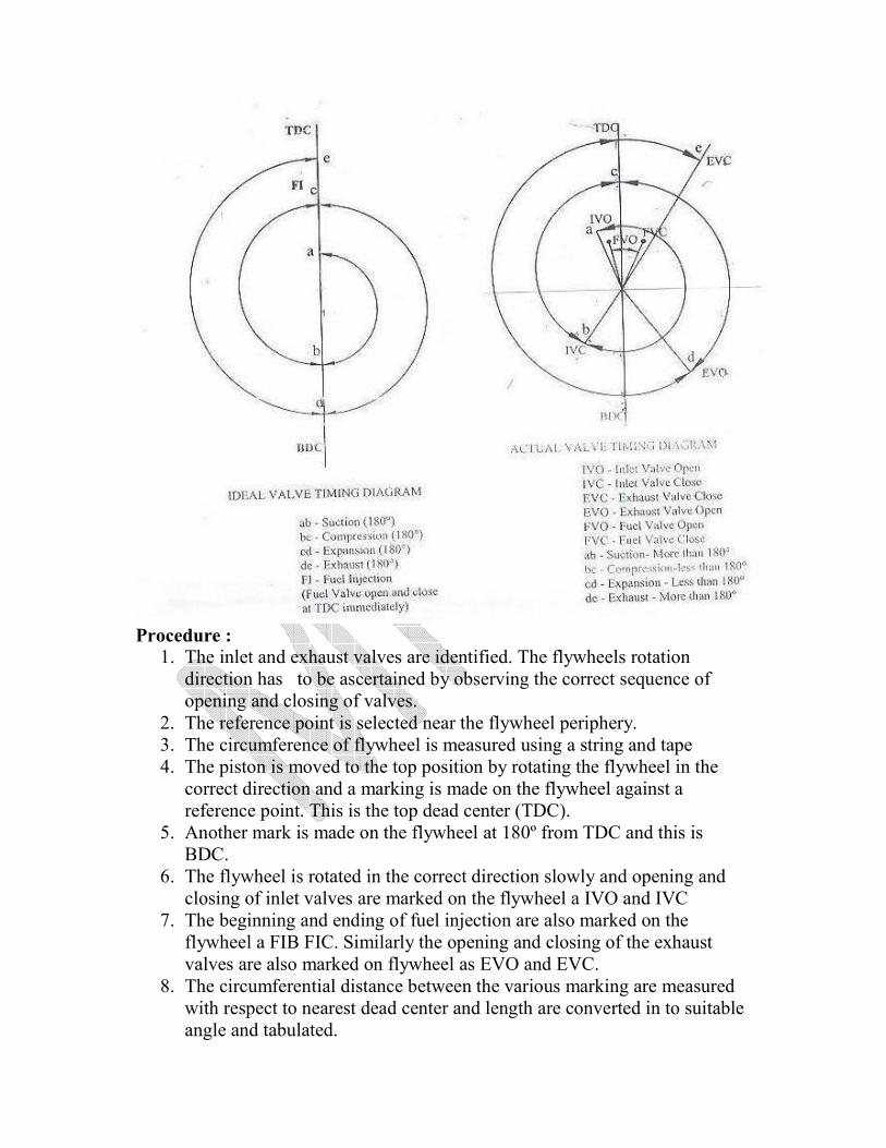
Procedure :
1. The inlet and exhaust valves are identified. The flywheels rotation
direction has to be ascertained by observing the correct sequence of
opening and closing of valves.
2. The reference point is selected near the flywheel periphery.
3. The circumference of flywheel is measured using a string and tape
4. The piston is moved to the top position by rotating the flywheel in the
correct direction and a marking is made on the flywheel against a
reference point. This is the top dead center (TDC).
5. Another mark is made on the flywheel at 180º from TDC and this is
BDC.
6. The flywheel is rotated in the correct direction slowly and opening and
closing of inlet valves are marked on the flywheel a IVO and IVC
7. The beginning and ending of fuel injection are also marked on the
flywheel a FIB FIC. Similarly the opening and closing of the exhaust
valves are also marked on flywheel as EVO and EVC.
8. The circumferential distance between the various marking are measured
with respect to nearest dead center and length are converted in to suitable
angle and tabulated.
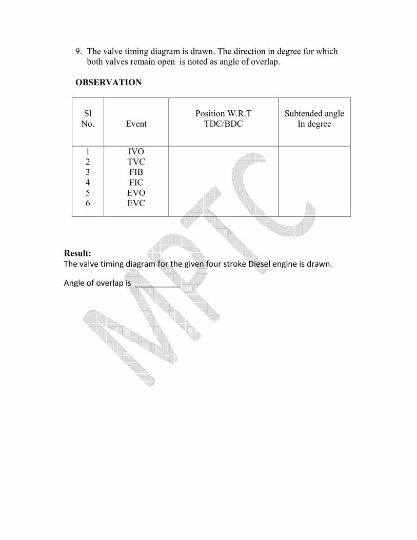
9. The valve timing diagram is drawn. The direction in degree for which
both valves remain open is noted as angle of overlap.
OBSERVATION
Sl
No.
Event
Position W.R.T
TDC/BDC
Subtended angle
In degree
1
2
3
4
5
6
IVO
TVC
FIB
FIC
EVO
EVC
Result:
The valve timing diagram for the given four stroke Diesel engine is drawn.
Angle of overlap is __________
REDWOOD VISCOMETER
Aim: To determine the kinematic viscosity and absolute viscosity of the given
lubricating oil at different temperatures using Redwood Viscometer
Apparatus required:
• Red wood viscometer
• Thermometer
• Stopwatch
• 50 ml standard narrow necked flask
Principle
The redwood viscometer consists of vertical cylindrical oil cup with an orifice
in the centre of its base. The orifice can be closed by a ball. Hooks pointing
upward serve as a guide mark for filling the oil. The cylindrical cup is
surrounded by the water bath. The water bath maintains the temperature of the
oil to be tested at constant temperature. The oil is heated by heating the water
bath by means of an immersed electric heater in the water bath. The provision is
made for stirring the water which is to maintain the uniform temperature in the
water bath and to place the thermometer to record the temperature of oil and
water bath. This viscometer is used to determine the kinematic viscosity of the
oil.
Precautions:
• The temperature of oil during the test period should not vary more than
0 – 20C.
• The temperature difference between the oil and water both should not
exceed 20C.
• The oil should not be stirred during the test period.
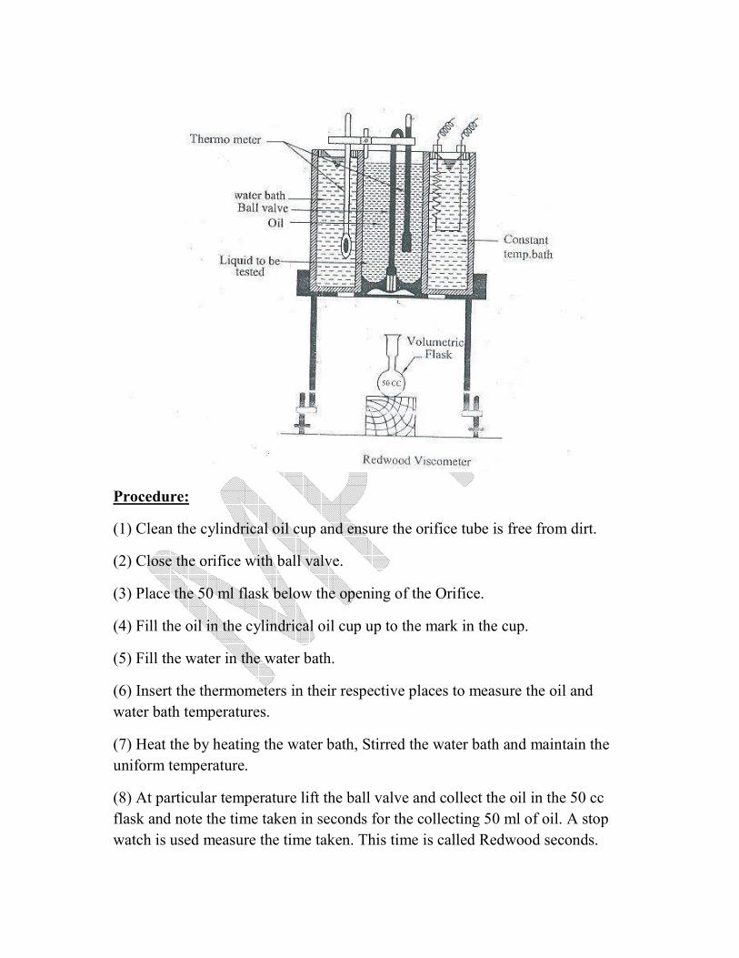
Procedure:
(1) Clean the cylindrical oil cup and ensure the orifice tube is free from dirt.
(2) Close the orifice with ball valve.
(3) Place the 50 ml flask below the opening of the Orifice.
(4) Fill the oil in the cylindrical oil cup up to the mark in the cup.
(5) Fill the water in the water bath.
(6) Insert the thermometers in their respective places to measure the oil and
water bath temperatures.
(7) Heat the by heating the water bath, Stirred the water bath and maintain the
uniform temperature.
(8) At particular temperature lift the ball valve and collect the oil in the 50 cc
flask and note the time taken in seconds for the collecting 50 ml of oil. A stop
watch is used measure the time taken. This time is called Redwood seconds.

(9) Increase the temperature and repeat the procedure ‘8’ and note down the
Redwood seconds for different temperatures
Observation:
ρx = 0.25
A = 0.22
B = 171.5
Tr = 147
S.no Temperature
of oil 00C
Time for
50cc ‘t’
Dencity Kinematic
viscosity
centistokes
Abs.
Viscosity
centipose
1
Formula:
ρT= ρR-0.00065(T- TR)
Kinematic viscosity = AxT – B/T Centistokes
Absolute viscosity = K.V x ρT Centipoises
Result:
Relative, Kinematic, Absolute viscosities are found out and graphs are plotted.
Kinematic viscosity =
Absolute viscosity =