study of the molten metal migration in the oxide porous … · study of the molten metal migration...
TRANSCRIPT

STUDY OF THE MOLTEN METAL MIGRATION IN THE OXIDE POROUS MATRIX
V. Asmolov, Yu. Degaltsev, O. Shakh, S. Abalin, I. Semenov, I. Isaev, K. Pechalin, V. Vlasov, Yu. Utkin, A. Kovalev, N. Kiselev
RRC “Kurchatov Institute”, Moscow, Russia
Abstract
From the viewpoint of modelling the reactor core damage in the course of a severe accident, the behaviour of the core debris on the reactor vessel lower head is the process of a high significance. It is recognised at the MASCA Project Meetings that the interaction of metallic melts with the corium oxidic debris bed is the issue of importance. The relocation of these metallic masses is of interest for modelling of impacts on the reactor vessel.
Therefore, organizing studies under the MASCA Project a special emphasis was laid on the investigation of molten steel or alloy of zirconium with stainless steel penetration into the porous corium debris.
10 tests were carried out in the KORPUS facility as well as one test in the TULPAN facility within the MASCA Project. The performed test matrix was intended to investigate the influence of following parameters:
• sizes of particles; • compositions of metallic melts; • the temperature variation rate, gradient, and maximum value; • the corium composition (suboxidised, completely oxidised); • the test scale, and • some other parameters. The employed experimental technique and obtained results are outlined in this paper.

Introduction
In 1998 an expert group from the NEA/OECD recognized that the migration of the molten materials was one of the domain of essential uncertainties due to limited base of experimental data and consequently insufficient knowledge had an effect on the simplification of models employed in the codes assessing the consequences of severe accidents [1].
In case of accident, it is assumed that relocated molten materials come into water and fragmented into debris of quite small sizes. This process was studied in detail in the FARO facility [2]. At the average, 50 % of particles had a size less than 4 mm in all tests.
According to the data of the reference [3], from 3 up to 10 % of elements had a size less than 1 mm after the accident at the TMI-2.
Thus, the matter concerns the significance of studying some phenomena taking place under relatively low temperature (ranging from 1200°C up to 2000°C) when that of the corium particles is still far off the melting temperature but liquid metallic phases are already appearing. Relocation of molten metals in the lower head and its penetration may accompany by the interactions with the corium debris.
The question of interactions between molten zirconium and uranium dioxide is one of the concerns. Such interactions were studied earlier [4] and it was found that this process might influence the formation of molten materials.
Thus the objectives for the tests were to study migration of molten metals formed in course of accident through the porous corium debris. The parameters varied were the major parameters which may determine the interaction process, such as:
• sizes of particles; • compositions of metallic melts; • the temperature variation rate, gradient, and maximum value; • the corium composition (suboxidised, completely oxidized); • the test scale, and • some other parameters.
To achieve experimental goals a total of 10 small scale tests were conducted. Moreover 3 supporting tests were conducted using the Laboratory oven with tungsten crucible as well as one supporting test in STFM facility. In addition one middle scale test T-7 was conducted using TULPAN facility. The experimental matrix and major parameters of the test are presented in Table 1.
2

Table 1. Test matrix and major Parameters of Performed Tests
Corium Metal #
Type Mass, g Porosity, % Quality Mass, g VV
pore
Meliq.
Test temperature,
°С
Metal penetration into
the loading
Interaction of steel St-30 with corium debris К-1 С-321) 117.00 38.0 St-30 95.50 1.70 1600 down to bottom К-2 С-32 80.00 ~50.0 St-30 95.50 1.33 1600 ~ 2.8 mm К-4 С-32 81.00 48.0 St-30 64.80 0.96 1800 down to bottom D-1 C-32 10.0 St-30 14.6 0.5 1800 Complete К-3 С-100 90.30 43.0 St-30 96.00 1.48 1600 ~ 0.2 mm
Interaction of stainless steel with corium debris D-3 C-32 10.0 12X18H10T 14.6 0.25 1800 Complete К-10 С-32 248.9 51.2 12X18Н10Т 259.46 1.11 2050 down to bottom T-75) C-32 4026 51.0 X18H10T 3450 1.0 2050 Complete
Interaction of 85SS/15Zr with corium debris К-74) С-32 45.37 51.0 85SS/15Zr3) 43.00 1.01 1800 1.27 mm К-5 С-32 80.20 49.0 85SS/15Zr2) 63.70 0.92 2050 3.2 mm D-2 C-32 85SS/15Zr 0.25 1800 Partial К-84) С-70 46.33 46.0 85SS/15Zr2) 44.00 0.98 1800 0.71 mm К-6 С-100 65.90 41.0 85SS/15Zr2) 46.15 1.06 1600 1.4 mm К-94) С-100 67.86 41.0 85SS/15Zr2) 44.00 0.98 1800 0.34 mm
1) Corium fragments of ~8 mm size. 2) Briquette pressed from the mixture of zirconium and stainless steel powders (85 mass %
of SS + 15 mass % of Zr) hot-extruded in the protective casing. 3) Alloy of 85 mass % of SS and 15 mass % of Zr. 4) Assemblies K-7, K-8 and K-9 were placed inside one heater and were heated
simultaneously. 5) Non isothermal test conditions.
Test Technique
Tested Materials
Coria of different compositions namely C-32, C-70, C-100 compositions with the atomic ratio of U/Zr = 1.2 were employed in the tests. Most part of experiments was conducted with the corium particles loading with the sizes of particles 1.2 - 3.5 mm, and one test (the K-1 test) was with the corium fragments of ~ 8 × 8 × 10 mm size.
The molten metals were presented by the steel of the St30 quality, stainless steel 12X18H10T, and by the alloy of stainless steel (85 mass %) and zirconium (15 mass %)
The corium fragments and particles were produced by cutting or crushing of the corium sintered briquettes (the C-32 corium was sintered under the temperature 1700°C, the C-70 and C-100 coria were sintered under the temperature 2000°C). The particle fractions were prepared by the altering bolting through the riddle with openings of 1.2 and 3.5 mm.
3

Figure 1 illustrates the size distribution of the corium particles.
KORPUS facility
Most tests were performed in the KORPUS facility in the argon atmosphere (Figure 2). The heating device consisted of a resistive graphite heater of a cylindrical geometry and up to 20 kW power. A tantalum shell in which studied test assemblies were placed was located in the heater.
As a rule, one test assembly was placed into the heating device in each test. In one case three test assemblies, K-7, K-8, and K-9, were tested simultaneously in one heating device. Test conditions for these assemblies were the same ones. Energy to heat a test assembly was transferred by the radiation from the graphite heater to the tantalum shell and from the Ta shell to the test assembly.
Temperature was measured within the temperature range 1400°C – 2300°C by W/Re thermocouples (TCs) and optical pyrometer calibrated for the tungsten radiating surface. The measurement error was ± 20°C. Pressure in the protection chamber was measured by a differential sensor with the measurement range ∆p = 760 mm Hg. Readings from all sensors were recorded by the data acquisition system.
The technique for all tests conduction was similar and consisted in several steps, which are described in details in the Report MP-TR-5 [5]. Typical temperature history for all tests is shown in Figure 3 using as an example temperature measurements in the K-5 test.
Laboratory Tests in a Tungsten Crucible
As K test series was conducted in a carbon heater three supporting tests were conducted to study the possible carbon influence on the test results. The tests were conducted with the C-32 corium briquette of the size of 15 × 15 × 15 mm. Steel St-30 or SS ring plate (See Figure 4) was placed onto the briquette. The space between the steel ring plate and a tungsten wall was filled with the C-32 corium particles. The debris temperature was measured by the W/Re thermocouple.
Test D-1 through D-3 were performed under the temperature T = 1800°C in argon atmosphere with the overpressure 0.3 atm. The exposition time under the temperature T = 1800°C was 30 minutes.
In the D - 2 test the mixture of SS (85 mass %) and Zr (15 mass %) was used. The sample was of a pyramid shape with the area contacting with the corium ~ 1.5 cm2 (Figure 5).
The TULPAN T-8 Test
The T-8 test was performed in the TULPAN facility to study the interaction of the C-32 corium particles with stainless steel in non isothermal conditions and in a larger scale. One of the goals was to determine the depth to which molten steel may penetrate through the porous debris. The goals for the posttest examination was also to study interactions occurred during penetration.
The TULPAN facility represents a gas-vacuum induction furnace with a graphite heater. The inductor power at the frequency 1000 Hz is up to 250 kW. The temperature gradient was maintained by the radiation from the outer surface of the test unit.
Figure 6 illustrates the test section layout and test unit itself is shown in Figure 7.
The intermediate steel bottom (1) was located in the steel protective casing (2). The protective casing of 340 mm diameter and 120 mm high was placed on the support (3). Two tiers of the C-100 corium briquettes (5) serving for radial thermal insulation were put on the intermediate bottom. The C-32 corium grits (8) were loaded into the gap between the briquettes and protective casing. ZrO2 crucible of 174 × 10 mm diameter and 90 mm high (4) was located inside the cavity between the C-
4

100 briquettes. The crucible was filled with a layer of the C-32 corium particles (6) 55 mm thick and of 154 mm diameter. A stainless steel X18H10T plate ~ 25 mm thick and of 152 mm diameter (7) was situated on this layer.
The temperatures in the facility were monitored by the system of thermocouples measuring the temperature on the structures, in thermal insulation and in the gas medium.
The following parameters were monitored in addition to the temperatures: • voltage, current, and power with regard to cosϕ in the inductor; • argon flow rate and pressure; • CO content in the atmosphere of the gas-vacuum chamber; • cooling water flow rate and temperature in the inductor coils.
Temperatures in TU were monitored by the system of thermocouples consisting of 8 Cr/Al thermocouples and 10 W/Re thermocouples. Figure 7 shows the schematics for the location of thermocouples. Thermocouples (TCs) were located symmetrically relative to the TU central axis approximately in one and the same diametral plane:
• 9 W/Re TCs 5-20 were located in the C-32 corium particles at 3 levels along the height and at 3 radii;
• 1 W/Re TC 5-20 was located in the opening in the steel plate.
In the test course, the steel maximum temperature achieved ~ 2050°C. The temperature of the corium particles loading at the lower level of thermocouples was ~ 1300°C (T9).
Test matrix and Results
Table 1 demonstrates the basic parameters for the performed tests. As a rule, the steel melt volume exceeded the volume of pores in the corium loading except of three D tests, which were conducted with the corium briquettes.
After test was completed, crucibles were filled up with epoxy and cut along the diameter in the vertical direction. A macrosection was prepared from one crucible half in which a general pattern of the metallic melt interaction with the corium particles corium was studied. Microsections of individual interaction zones were prepared from the second crucible half aiming to obtain images with a large magnification and to determine the element composition of individual phases.
The methods of optical microscopy (Neophot 30) with a quantitative element analysis in the micro analyzer Comebax 50SX were employed for the study.
Behavior of the Carbon Steel ST-30 Melt
Four experiments were conducted to study the interaction of St-30 steel with the debris made of C-32 corium, and one test utilized C-100 corium. In the test K-1, the corium briquettes were used and molten steel penetrated into the gaps between the fragments of the C-32 corium briquettes in all layers and reached the crucible bottom at relatively low temperature of 1600oC. The minimum gap in which steel was able to penetrate was about 0.2 mm (See Figure 8).
In the test K-2 the debris was formed of particles (See Figure 9), molten steel penetrated at temperature of 1600OC into the corium C-32 loading at a depth of ~ 2.8 mm. Temperature increase to 1800oC (Test K-4 with the same corium particles as in the test K-2) caused penetration to the bottom of the crucible as it is shown in Figure 10. This figure demonstrates also the microstructure of samples cut out of the ingot upper and lower parts and the microprobe analysis results. It can be seen that a partial interaction of steel with the corium particles took place in the crucible lower part resulted in the
5

mixture melting. This is indicated by the ingot structure containing the iron matrix with dendrites of intermetallic compounds Fe3Zr and Fe3U with the impurity of zirconium.
Similar metallic phases were found in the interaction zone of the K-2 test (Figure 9).
Thus, the temperature increase by 200°C in comparison with that in the test K-2 resulted in the complete leaking of liquid steel St-30 through the C-32 corium particles in a partial melting of interacted products in the crucible lower part.
At 1800oC steel St-30 penetrates through the pores of the corium briquettes with the porosity of about 10% as it was observed in the D-1 test. The metallographic study demonstrated vertical streams of the light metallic phase (Figure 11) observable throughout the volume of the C-32 corium.
Experiment K-3 conducted with the C-100 corium demonstrated significantly less penetration of the steel in the corium (0.2 mm at 1600oC). The penetration pattern was not the continuous filling of pores but steel diffusion over surfaces of the corium particles. Steel did not penetrate deeper into the particles and the latter freely spilled out of the UO2 crucible.
In the test with the C-100 corium (Figure 12) the following basic phases were observed: • of the (U0.9Zr0.1)O2.0oxidic type with the impurity of Fe and • of iron with the impurity of oxygen (3-8 at%).
Behavior of Stainless Steel
Stainless steel of the following chemical composition given in mass% was employed in the test K-10: Cr - 18.1; Ni - 10.2; Mn - 0.78; Si - 0.63; Ti - 0.41; Mo < 0.01; Fe – the rest part. In general the behavior of stainless steel observed in the tests K-10 and D-3 was similar to the behavior of St-30 steel.
At temperature of 1800oC molten steel leaked through the corium briquettes with the porosity about 10% as it is shown in Figure 13. In the test K-10 molten steel under T = 2050°C leaked through the C-32 corium particles and partially leaked out of the crucible due to the crucible bottom degradation desiccating the corium particles in the upper part (Figure 14a).
Figure 14b shows the C-32 corium particles that partially interacted with steel. In the area “1”, a good wettability of the corium particles by liquid steel (the wetting angle ~ 45°C) is seen well. Figure 14c demonstrates the interface between the corium C-32 particle and liquid steel. A partial steel penetration into the corium is also seen clearly as well as the produced intergranular streaks of intermetallic compounds of Fe-U-Zr similar to those produced in the test K-2.
Results of middle scale tests TULPAN T-8
Additional information on steel behavior was obtained from the test TULPAN T-8. As it was mentioned this test was conducted in the conditions of the vertical temperature gradients. The cross section of ingot obtained after the test is shown in Figure 15.
On examining the macrosection of the ingot central section, the following was noted: • Steel was melted and leaked through the corium particles down to the depth ~ 35 mm from
the lower surface of initial steel filling the porosity among particles; the lower boundary of steel penetration was rectilinear.
• Approximately 25 % of initial steel form a layer ~ 8 mm thick. ZrO2 crucible walls were wetted by steel (Figure 15), the wetting angle Θ ≅ 70°.
6

• Separate portions of particles with a light surface similar to those observed in the K-5 test were observed in the loading in the ingot lower part below the lower boundary of steel penetration.
• A total thickness of the loading layer was reduced after the test by ~ 15 mm (~ 25 % of the initial thickness).
Thermocouples T7 and T9 were located approximately 3 mm lower than the lower front of the leaked alloy and showed the temperatures 1170°C and 1310°C, respectively, that approximately by 100 - 250°C lower than Tmelt of steel.
Figure 16 shows the macrostructure of the sample #1 (Figure 15). Table 2 contains the microprobe analysis results.
Two basic phases were observed in the sample #1 (T ≅ 1600°C): 1. The light one among the corium particles (1.1.) was of the steel composition with some
abnormal Cr/Ni ratio and with striations of the (Fe0.48Cr0.05Ni0.21)Zr0.2U0.06 composition observable only in electron rays (1.1.2). These two phases did not contain oxygen.
2. The spotty phase representing the corium particles consisted of grey grains (1.3) typical of the corium (U0.8Zr0.2)O2 of the oxidic phase and of the light metal phase (1.2) presenting steel with a low impurity of U.
Table 2. Typical Microstructure of the T-8 Middle Part (Sample #1,Figure 15)
Fe Zr U C Ni Cr O #
Concentration (mass%) Sum Point Comment Composition
Averaged according to the changes in three points
1 69.95 0.06 0.04 0.11 5.41 23.17 0.00 99.23 1.1. Grains in the light
field Fe0.7Cr0.25Ni0.05
2 35.66 23.43 19.55 0.00 16.52 3.41 0.00 98.45 1.1.2*)
Impurities at the
boundary of grains
Fe0.48Ni0.21Cr0.05Zr0.2U0.06
3 70.33 0.00 0 0.01 6.86 20.76 0.00 98.98 1.2 Light grains Fe0.7Cr0.23Ni0.06U0.01
4 0.05 7.64 79.54 0.00 0.05 0.00 12.97 99.93 1.3 Dark grains (U0.8Zr0.2)O2.0
*) impurities 1.1.2 were segregated only by the microprobe analysis and were not observable in the optical microscope.
Figure 17 illustrates the microstructure of the sample #2 (Figure 15). Table 3 presents the microprobe analysis results for the ingot lower part (Sample #2)
Filling of gaps among the corium particles was not observed in the lower sample but separate corium particles were observed that interacted with steel according to the mechanism “vaporization-condensation-diffusion” generating oxygen-free intermetallic compounds (UZrFeCrNi).
Light impurities 2.1 consisted of two phases: 2.1.1 and 2.1.2 (Table 3) and were approximately equal in areas (could be segregated by the microprobe analysis). Grey impurities were close in composition to U6Fe.
7

Table 3. Typical Microstructure of the Ingot Lower Part
Fe Zr U C Ni Cr O #
Concentration (mass%) Sum Point Comment Composition
5 10.22 33.47 49.29 0.00 6.07 0.03 0.00 99.73 2.1.1*) Light impurities Zr0.43U0.24Fe0.21Ni0.12
6 36.15 42.93 7.58 0.00 2.43 10.83 0.01 99.82 2.1.2*) Light impurities Zr0.33U0.02Fe0.47Cr0.15Ni0.03
7 3.54 0.35 95.54 0.00 0.26 0.00 0.00 99.44 2.2 Grey impurities U0.84Fe0.14Zr0.01Ni0.01
*) impurities 2.1.1 and 2.1.2 were differed only by the microprobe analysis.
Behaviour of Stainless Steel – Zr Alloy
Remaining experiments were conducted with the alloy made of 85 mass % of SS + 15 mass % of Zr. Figure Figure 18 illustrates macrosections from the tests K-7, K-5, K-8, K-6, and K-9. It can be seen that the metallic melt (SS + Zr) leaked through the corium particles in neither of the tests. Wetting of the ZrO2 crucible walls by the melt was not also observed.
The penetration depth depended upon temperature and corium composition. For example, in the K-7 test the penetration was about 1.3 mm while with temperature increase the penetration increased also, 3.2 mm for the K-5 test at 2050oC. Comparing K-7, K-8 and K-9 tests at the same temperature of 1800oC, the penetration depth decreases with the increase of oxidation degree: from 1.3 mm for C-32 to 0.71 and 0.34 for C-70 and C-100 correspondingly.
Let us consider the interactions of alloys with the coria of different types.
Interactions with the highly oxidized corium
Wetting of the C-70, C-100 coria particles by the melt and the melt leakage into the gaps among the particles were not observed in all three tests. The melt interaction with a high-oxidized corium C-100 was studied in more detail in the test K-6 taken as an example.
Figure 19 shows the macrostructure of the melt (SS + Zr) boundary layer with 2 - 3 particles of the C-100 corium (the test K-6, T = 1600°C). Three layers separated by clear boundaries being “parallel” to the surface of the contact with the melt were observed in the C-100 corium particle located in the direct contact with the SS + Zr melt. The layers are 0.5, 0.9, 0.7 mm thick beginning from the melt boundary.
The element composition of layers was studied by the microprobe analysis employing different diameters of electronic probes. Table in Figure 19 presents the microprobe analysis results obtained by a large diameter probe (∅ ~ 50 µm). They indicated that the crystallized melt (area #1) near the boundary with the C-100 particle consisted of stainless steel (~ 87 at %), carbon, zirconium (~ 12 at %) that was close to the alloy initial composition. Besides, approximately 1 at% of uranium was found out in the alloy.
Stainless steel (up to 60 at %) was found out in the solid C-100 corium (area #2) with the initial ratio of elements including carbon.
In the third area, the content of stainless steel was reduced down to ~ 40 at %. The quantities of uranium and zirconium in the form of oxides with the reduced content of oxygen were about 60 at %.
8

Contents of the area #4 of the C-100 corium particle being in the contact with the melt and of the particle in the area #5 not contacting with the melt were close to that of the C-100 corium.
The analysis of the corium phases by the point probe (∅ ~ 1 - 2 µm) is illustrated in Figure 20. A light phase close to SS and a dark oxidic phase containing uranium and zirconium with the ratio of U/Zr = 0.14 at % (in the initial corium U/Zr = 1.2 at %) were detected in the corium area #2 that confirmed uranium migration into the melt.
The area #3 contained 2 phases:
I phase presented a grey oxidic base of the ~ (U0.8Zr0.2)O1.7-1.8 composition with the reduced quantity of zirconium as compared to the initial C-100 corium.
II phase was of a white colour and presented zirconium oxycarbide.
The areas ## 4 and 5 far from the melt boundary presented a one-phase corium close in the composition to the C-100 corium with the unbroken initial U/Zr ratio.
Interactions with the C-32 Corium
The SS+Zr alloy penetration into the porous corium loading (Figure 21, Figure 18) was observed in the test K-7 and especially in the test K-5. However, this penetration took place not by the leakage of the liquid melt through the gap system in the corium loading particles but, apparently, by the “surface” diffusion over the surfaces of the corium particles (Figure 22a) as well as by the mechanism “vaporization – condensation” (Figure 21 and Figure 18, the test K-5).
The melt first relocated by the mechanism “vaporization – condensation” then penetrated by diffusion in depth of the particles loading, as this was discussed in detail in the test K-6, and produced a two-phase system (Figure 22a) which included the following:
• a light metallic phase containing stainless steel of the composition close to the initial one and zirconium the quantity of which approximately 2 times exceeded that in the initial alloy;
• a grey oxidic phase (U1.3Zr)O2.
Figure 22b, c shows the structure of the metallic SS+Zr alloy cut out of the metallic ingot upper (b) and lower (c) parts.
The melt was crystallized into a two-phase system: • the one close in composition to stainless steel (Fe0.7Cr0.25Ni0.05) • the intermetallic compound of the (SS3Zr) approximate composition.
Up to 4 at % of uranium was observed in the ingot lower part near the corium particles that coincided with the investigation results for the test K-6.
Discussion on findings
The corium (UZr)O2-x particles were employed in the tests with different contents of oxidized zirconium from 32 % up to 100 % (Cn = 32 - 100). Particles were sized within the range 1.2 - 3.5 mm. Steel St-30, stainless steel 12X18H10T and alloy of stainless steel (85 mass %) with zirconium (15 mass %) were used as liquid metals.
Results of experiments demonstrated several mechanisms for the penetration of molten metal in the porous debris:
• Filling of the open porosity among particles by liquid metal. This process depends upon the debris particle size, the wettability of the corium particles and surface tension which are in turn depend upon composition and temperature;
9

• The interactions between molten metals and corium particles near the contact area between phases. The depth of such penetration did not exceed ~ 3.2 mm.
• In some cases (under the temperature higher than 1800°C) the metal migration by the mechanism “vaporization-condensation” on the surface of particles located deeply in the loading was found
Molten steel demonstrated good ability to penetrate into the corium if the temperature of steel exceeds its melting point by 350 K. At the temperature of 1600°C steel penetrated only if the size of pores is large enough. However at temperature higher than 1800°C, steel penetrate not only in the debris formed by particles of 1.2 - 3.5 mm, but also through the corium briquettes with the low porosity (about 10%). TULPAN T-8 test conducted in the vertical temperature gradient indicated that the penetration of steel was observed up to the temperature about its melting point.
However the composition containing the alloy of stainless steel and zirconium (85 % SS + 15 % Zr ) demonstrated weak wettability and consequently the penetration ability even in the cases when superheating above the melting point was 400 – 500°. The wetting angle was assessed to be ~ 150° (See Figure 18).
The most probable reason for the lack of wetting is as follows. In contact with the gas or liquid on the surface of the 85 % SS + 15 % Zr liquid films of low-volatile and insoluble materials [6] may be formed which increases sharply the limiting wetting angle. Carbon contained in SS may form refractory zirconium carbide that comes to the surface due to “adsorption” and increases the wetting angle. This may explain the experiments with steel St-30 at the temperature of 1600°C if the Fe3C film with the melting temperature of 1650°C [7] is formed on the surface of molten steel.
This hypnoses was confirmed in the test K-6. As one can see in Figure 9, a heightened carbon concentration (~ 2 at % - in metal and ~ 8 at % - in the corium) is near the boundary “liquid metal – the C-100 corium” (the carbon content in the initial alloy 85 % SS + 15 % Zr does not exceed 0.5 at %).
The contact interaction of the corium with any Cn value with liquid metals was observed under all test temperatures (starting from 1600°C). In principle, the interaction leads to the diffusion release of U and Zr from the contacting layer of the corium particles into liquid metal (up to ~ 5 at %) and to the diffusion of steel components Fe, Cr, Ni into the corium solid particles forming complicated compounds of the metal type. They are oxygen-free or with low oxygen content. The thickness of the interaction layers is increased with the decrease of Cn. However, the interaction was observed also in the completely oxidized corium (Cn = 100).
The oxidic phase of the corium particles (UZr)O2-x varies to a less degree. This may include metal atoms of steel up to ~ 10 at % with respect to U + Zr (for example, [U0.7Zr0.2Fe0.1]O2-x).
Aiming to obtain more complete information about the behaviour of the corium particles in liquid metal, it is worthwhile to perform a test with a durable exposition under a high temperature (for example, up to 10 hours) and to refine some issues of the influence of the temperature, size of pores, etc.
Improvement of understanding about the zirconium and stainless steel alloy penetration into the porous medium of the corium particles, it seems expedient to continue studies in the line of the temperature range increase (up to 2300°C) and employment of other alloys' composition.
Conclusions
Thus, in the case of the MASCA project prolongation, two lines of studies seem to be expedient for the investigation of the liquid metal and alloy behaviour in the porous medium of the corium particles:
10

• Studies of the behaviour of metals in the oxidizing environment; • Further studies of the nature for the behaviour of alloys zirconium – stainless steel with other
alloy compositions under the maximum possible (from the viewpoint of the operating capability of test devices) temperature rise.
11

Figure 1. The Size Distribution of the C-32 and C-100 Coria
C-32
C-100
Figure 2. Layout of the Heating Device with the Test Assembly in the KORPUS Facility
D 40
7030~2
0
T1 T2
ПИР. 5
D 28
D 30
Ar
1
2
3
4
5
6
7
9
8
10
8
1. graphite heater; 2. Ta shell; 3. steel; 4. W crucible; 5. corium loading; 6. ZrO2 (or UO2) crucible; 7. W support; 8. carbon-fibrous thermal insulation; 9. graphite disc; 10. Mo casing with ZrO2 cladding.
12

Figure 3. Typical temperature history for the Series of Tests K-1 – K-10 (Test K-5)
0 60 120 180 240Time (min)
0
500
1000
1500
2000
2500Te
mpe
ratu
re (o C
)T2Pyr 5
T1
Figure 4. The Layout of the Tests D1 and D3
1
2
3
4
5
6
1. Steel St-30 or SS (12X18H10T); 2. C-32 particles; 3. C-32 briquette; 4. Tungsten crucible; 5. Tungsten heater; 6. W/Re thermocouple.
Figure 5. The Layout of the D2 Test
1
2
3
4
5
6
1. SS(85 mass %) and Zr(15 mass %); 2. C-32 particles; 3. C-32 briquette; 4. Tungsten crucible; 5. Tungsten heater; 6. W/Re thermocouple.
13
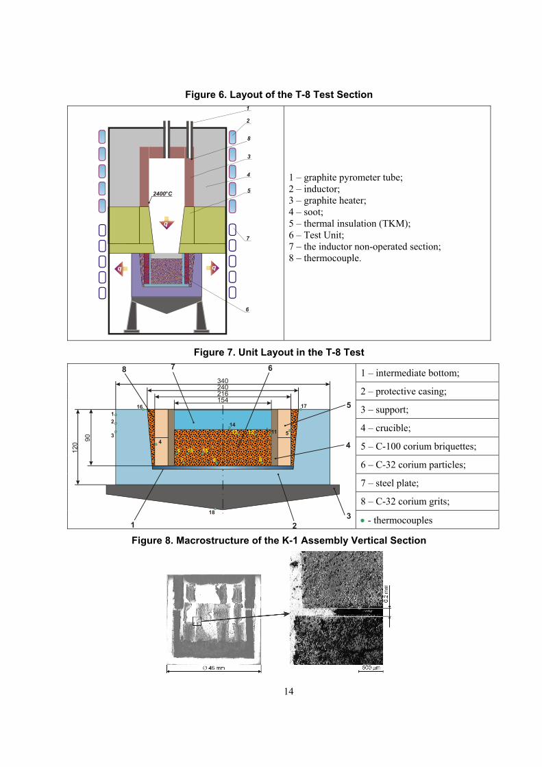
Figure 6. Layout of the T-8 Test Section
2400°C
q
2
3
4
5
6
7
8
1
1 – graphite pyrometer tube; 2 – inductor; 3 – graphite heater; 4 – soot; 5 – thermal insulation (TKM); 6 – Test Unit; 7 – the inductor non-operated section; 8 – thermocouple.
Figure 7. Unit Layout in the T-8 Test
1 – intermediate bottom;
2 – protective casing;
3 – support;
4 – crucible;
5 – C-100 corium briquettes;
6 – C-32 corium particles;
7 – steel plate;
8 – C-32 corium grits;
154216240340
14
17
1213
987
6 10 154
16
511
78 6
5
1 23
90
120
12
3
18
4
• - thermocouples
Figure 8. Macrostructure of the K-1 Assembly Vertical Section
14

Figure 9. Macrostructure and Results of the Element Analysis for the C-32 Corium
20 mµ
(U Zr Fe )O0.7 0.2 0.1 1.7
Fe Zr0.7 0.3
1521
24
2.8
Figure 10. Macro- and Microstructure from the Test K-4
15

Figure 11. Microstructure of the C-32 Briquette Upper Part after the Test D1
Upper part of the ingot Middle part of the ingot
Figure 12. Microstructure and Results of the Element Analysis for the C-100 Corium Particles
100 mµ
С-1
00 p
artic
les
Met
al
Fe
(U Zr )O0.9 0.1 2.0
Figure 13. Microstructure of the C-32 Briquette Upper Part after the Test D3
The C-32 briquette upper part The C-32 briquette middle part
16

Figure 14. Microstructures of the C-32 Corium Groats and of the Leaked Steel 12X18H10T
a) b) c)
Figure 15. Macrosection of the T-8 Tests
Figure 16. Steel Spreading in the Corium Debris Loading (the Ingot Middle Part,
Sample #1 in the Area of the Thermocouple T10, T ≅ 1600°C
17

Figure 17. Microstructure of the Sample #2 (the Ingot Lower Part)
Figure 18. Macrosections of Crucibles after the Tests K-6, K-7, K-8, K-9, K-5 К-7 С-32
К-5 С-32
К-8 С-70
К-6 С-100
К-9 С-100
1800°С 2050°С 1800°С 1600°С 1800°С
18

Figure 19. Macrostructure and the Microprobe Analysis Results (the Probe Diameter = 50 µm)
Fe Ni Cr Zr U C O
Concentrations of elements (mass%) Sum Dz
(µm) point Calculation formula
54.14 8.52 13.56 17.10 4.04 0.32 0.00 97.68 50 1 [(Fe0.71Cr0.19Ni0.10)0.87
Zr0.12U0.01]×С0.02
28.24 4.26 7.90 38.15 11.23 1.76 8.63 100.17 50 2 [(Fe0.69Cr0.20Ni0.11)0.61
Zr0.35U0.04]×С0.12O0.39
12.69 1.88 3.50 18.81 54.22 0.00 9.92 101.02 50 3 [(Fe0.69Cr0.21Ni0.10)0.44
Zr0.27U0.29]×O0.8
0.03 0.03 0.00 21.93 62.66 0.00 14.48 99.13 50 4 (U0.50Zr0.50)O1.8
0.03 0.02 0.00 21.28 65.22 0.00 13.04 99.59 50 5 (U0.55Zr0.45)O1.6
19
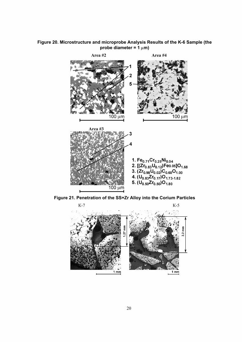
Figure 20. Microstructure and microprobe Analysis Results of the K-6 Sample (the probe diameter = 1 µm)
Area #2 Area #4
Area #3
Figure 21. Penetration of the SS+Zr Alloy into the Corium Particles К-7 К-5
20

Figure 22. Microstructure and Microprobe Analysis Results for the K-5 Sample The metallic sample upper part The corium C-32 grits
b) a)
The metallic sample lower part
c)
1. (Fe0.66Cr0.07Ni0.27)0.8Zr0.20 2. Fe0.70Cr0.25Ni0.05 3. (Fe0.70Cr0.17Ni0.13)0.72Zr0.28 4. (Fe0.72Cr0.18Ni0.10)0.69Zr0.31 5. (U1.3Zr)O2 6. (Fe0.71Cr0.25Ni0.04 7. (Fe0.73Cr0.12Ni0.15)0.76Zr0.24 8. (Fe0.66Cr0.70Ni0.27)0.74Zr0.22U0.04
21

22
References
1 Molten Material Relocation into the Lower Plenum: A Status Report. NEA/CSNI/R(97)34, September, 1998. 2 D. Magellon et. al., Debris and Pool Formation/Heat Transfer in FARO-LWR: Experiments and Analyses. Work shop Proceedings, March 3-6 1998. 3 H. Unger et. al., Key Phenomena of Late Phase Core Melt Progression, Accident Management Strategies and Status Quo of Severe Fuel Damage Codes. Workshop Proceedings, March 3-6 1998. 4 P. Hofmann et. al., Dissolution of Solid UO2 by Molten Zircaloy and its Modelling. International Symposium on severe accidents in Muclear Power Plants. Sorrento, Italy, 21-25 March 1988. 5 V.G. Asmolov, Yu.G. Degaltsev, O.Ya. Shakh, S.S. Abalin, I.M. Semenov, et al. Study of the Molten Metal Migration in the Oxide Porous Matrix. MP-TR-5, July 2003. 6 L.L. Kunin, Surface Phenomena in Metals, M., 1955 (rus) 7 G.V. Samsonov, Refractory Compounds, Metallurgizdat, M., 1963 (rus)