study of impact between two equal & unequal height of...
TRANSCRIPT
Vol-3 Issue-3 2017 IJARIIE-ISSN(O)-2395-4396
5792 www.ijariie.com 3914
“Study of Impact between Two Equal & Unequal Height of Building during Of
Earthquake”
S.B.ANANTWAD¹, Prof. V.G.PATWARI²
¹PG Student, M.E. (Structures) Civil Department M.S.Bidve College of Engineering Latur Maharashtra,
India.
²Assistant Professo M.E. (Structures) Civil Department M.S.Bidve College of Engineering Latur
Maharashtra, India.
ABSTRACT Increasing population and growing social and commercial activities but limited land resources available in a
modern city lead to more and more buildings being built closely to each other. These buildings, in most cases, are
separated without any structural connections. The ground motion during earthquakes causes’ damage to the
structure by generating inertial forces caused by the vibration of the buildings masses. From previous studies it was
observed that majority researchers did the work on the separation gap between two adjacent structures. Thus, after
reviewing the existing literature it was observed that most of literature compares existing & low-rise structure. The
project objective is to decrease the effect of earthquake responses on structures. The main objective and scope are to
evaluate the effects of structural pounding on the global response of building structures and to determine the
minimum seismic gap between equal and unequal but adjacent buildings. In this project using response spectrum
analysis we have checked whether two models have displacement within the permissible limit for adjacent buildings
as well as to determine & compare the seismic gap provided as per IS 1893-2002 and other codal provisions.
Keyword. - Structural pounding, Adjacent buildings, Seismic separation distance, Response Spectrum, Separation Gap, IS code, Deflection.
1. INTRODUCTION
Increasing population and growing social and commercial activities but limited land resources available in a modern
city lead to more and more buildings being built closely to each other. These buildings, in most cases, are separated
without any structural connections. Hence, wind-resistant or earthquake resistant capacity of each building mainly
depends on itself. The ground motion during earthquakes causes‟ damage to the structure by generating inertial
forces caused by the vibration of the buildings masses. Tall structures are extremely vulnerable to the structural
damage because the masses at the levels are relatively large, supported by slender columns. The displacement of the
upper stories is very large as compared to the lower ones. This includes large shear forces on the base columns. If
the separation distances between adjacent buildings are not sufficient, mutual pounding may also occur during an
earthquake. During strong earthquakes, adjacent structures that do not have appropriate distance and hit each other,
that is called impact. The difference between dynamic properties (mass, hardness and height) of adjacent structures
results different-phase oscillations which is the main cause to impact and the more different in shape of vibration
causes stronger impact and vice versa. Impact phenomenon has been reported in the strong earthquakes.
1.1 Separation Gap

Vol-3 Issue-3 2017 IJARIIE-ISSN(O)-2395-4396
5792 www.ijariie.com 3915
A separation gap is the distance between two different building structures often two wings of the same facility that
allows the structures to move independently of one another. Investigations of past and recent earthquake damage
have illustrated that the building structures are vulnerable to severe damage and/or collapse during moderate to
strong ground motion.
1.2 Objectives of Study
From literature survey, it was observed that majority researchers did the work on the separation gap between two
adjacent structures. Thus, after reviewing the existing literature it was observed that most of literature compares
existing & low-rise structure. In this thesis separation gap is determined & compared as per Indian codal provision
& other relevant codes. The objective of the thesis is to ensure that the overall building behaviour meets stated
performance objectives at serviceability and code design levels. The resulting design provides a level of safety and
overall building occupant comfort equivalent to that provided by building code requirements (Indian and in some
instances American) as well as good practices for tall buildings
2. LITERATURE REVIEW
1. Jankowski 2006a.
This paper proposes the idea of impact force response spectrum for two structures; peak pounding force vs. natural
periods. Pounding has been simulated by nonlinear viscoelastic model. The structural parameters, such as gap,
natural periods, damping, mass and ductility as well as the time lag of input ground motion records, might have a
substantial influence
2. Maison, Kasai 1992.
A formulation and solution of the multiple-degree-of-freedom equations of motion for floor-to-floor pounding
between two 15-storey and 8-storey buildings are presented. The influence of building separation, relative mass, and
contact location properties are assessed
3. Warnotte Viviance (2007)
Adjacent buildings subjected to seismic excitations collide against each other when the separation distance is not
large enough accommodate the displacement response of the structures relative to one another
4. Jeng et al (1998) Taipei City, with its high seismicity, soft soil condition, and many tall buildings without proper
seismic separation, is vulnerable to seismic pounding destruction similar to that occurred in Mexico City during the
1985 earthquake. Amar M Rahman et al (2000) Collisions between adjacent structures due to insufficient separation
gaps have been witnessed in almost every major earthquake since the 1960‘s.
3. STRUCTURAL MODELING AND ANALYSIS
In order to evaluate the Seismic separation gap between buildings with rigid floor diaphragms using dynamic and P-
Delta analysis procedures five case studies are adopted. Various methods of differing complexity have been
developed for the seismic analysis of structures. The three main techniques currently used for this analysis are:
1.Dynamic analysis.
Linear Dynamic Analysis.
Non-Linear Dynamic Analysis.
2. P-Δ (Delta) Analysis.
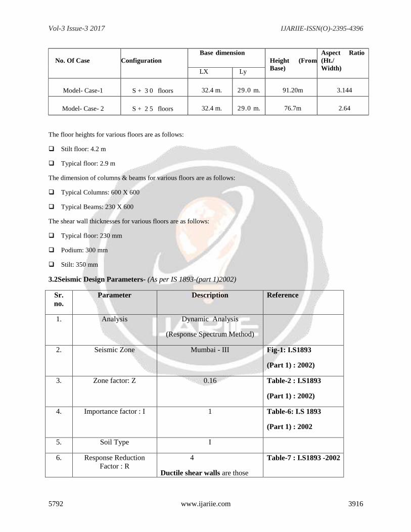
3.1 Brief Description of the Structure
Vol-3 Issue-3 2017 IJARIIE-ISSN(O)-2395-4396
5792 www.ijariie.com 3916
No. Of Case
Configuration
Base dimension
Height (From
Base)
Aspect Ratio
(Ht./
Width) LX Ly
Model- Case-1
S + 3 0 floors
32.4 m.
29.0 m.
91.20m
3.144
Model- Case- 2
S + 2 5 floors
32.4 m.
29.0 m.
76.7m
2.64
The floor heights for various floors are as follows:
Stilt floor: 4.2 m
Typical floor: 2.9 m
The dimension of columns & beams for various floors are as follows:
Typical Columns: 600 X 600
Typical Beams: 230 X 600
The shear wall thicknesses for various floors are as follows:
Typical floor: 230 mm
Podium: 300 mm
Stilt: 350 mm
3.2Seismic Design Parameters- (As per IS 1893-(part 1)2002)
Sr.
no.
Parameter Description Reference
1. Analysis Dynamic Analysis
(Response Spectrum Method)
2. Seismic Zone Mumbai - III Fig-1: I.S1893
(Part 1) : 2002)
3. Zone factor: Z 0.16 Table-2 : I.S1893
(Part 1) : 2002)
4. Importance factor : I 1 Table-6: I.S 1893
(Part 1) : 2002
5. Soil Type I
6. Response Reduction
Factor : R
4
Ductile shear walls are those
Table-7 : I.S1893 -2002
Vol-3 Issue-3 2017 IJARIIE-ISSN(O)-2395-4396
5792 www.ijariie.com 3917
designed and detailed as per IS
13920 Clause -6.4.2 , sr.no- 7
(Part 1) : 2002)
7. Seismic resisting
structural system
Ductile shear walls
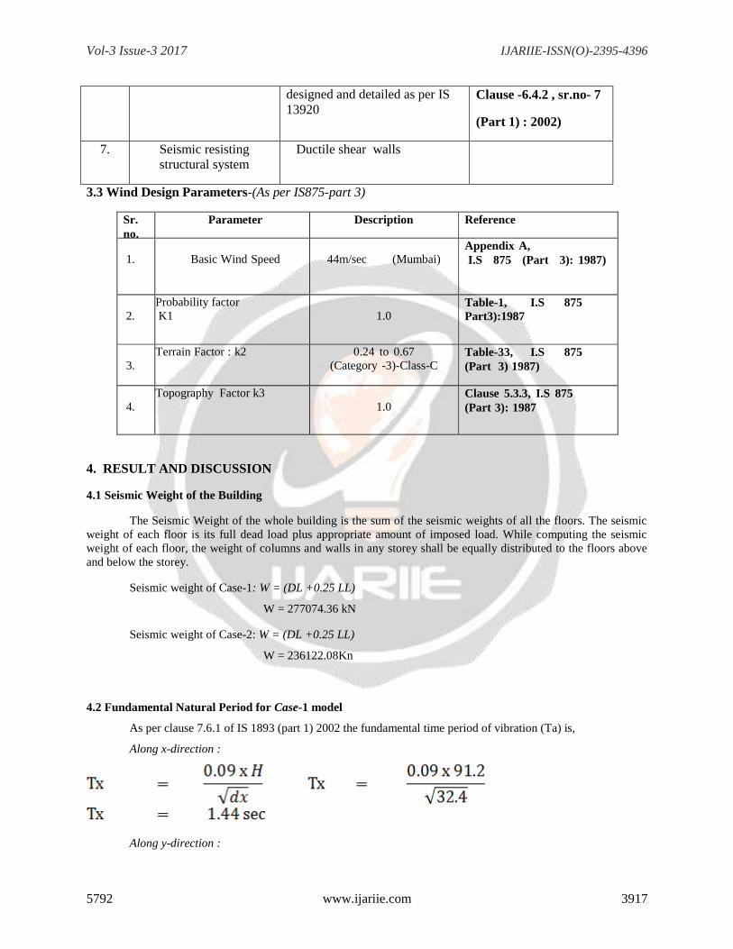
3.3 Wind Design Parameters-(As per IS875-part 3)
Sr.
no.
Parameter Description Reference
1.
Basic Wind Speed
44m/sec (Mumbai) Appendix A,
I.S 875 (Part 3): 1987)
2.
Probability factor
K1
1.0 Table-1, I.S 875
Part3):1987
3.
Terrain Factor : k2 0.24 to 0.67
(Category -3)-Class-C
/ Class C)
Table-33, I.S 875
(Part 3) 1987)
4.
Topography Factor k3
1.0 Clause 5.3.3, I.S 875
(Part 3): 1987
4. RESULT AND DISCUSSION
4.1 Seismic Weight of the Building
The Seismic Weight of the whole building is the sum of the seismic weights of all the floors. The seismic
weight of each floor is its full dead load plus appropriate amount of imposed load. While computing the seismic
weight of each floor, the weight of columns and walls in any storey shall be equally distributed to the floors above
and below the storey.
Seismic weight of Case-1: W = (DL +0.25 LL)
W = 277074.36 kN
Seismic weight of Case-2: W = (DL +0.25 LL)
W = 236122.08Kn
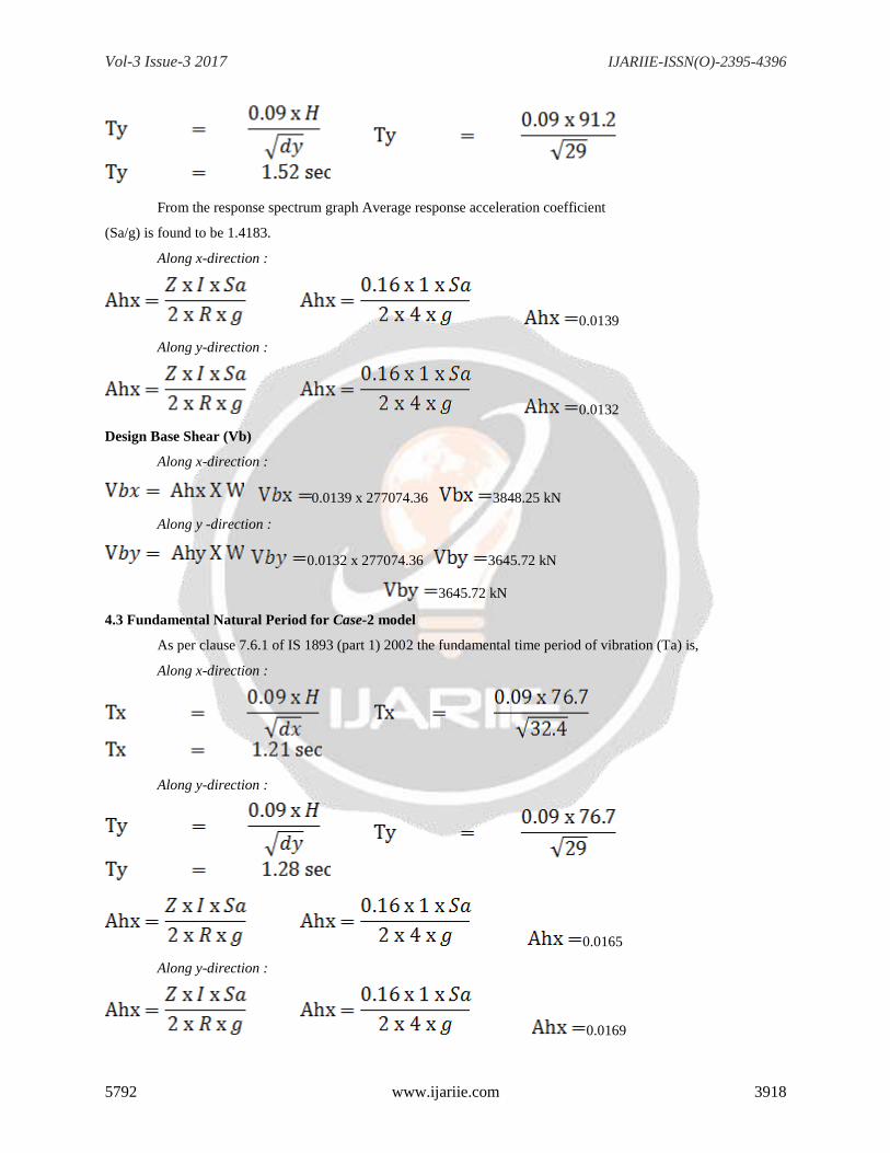
4.2 Fundamental Natural Period for Case-1 model
As per clause 7.6.1 of IS 1893 (part 1) 2002 the fundamental time period of vibration (Ta) is,
Along x-direction :
Along y-direction :
Vol-3 Issue-3 2017 IJARIIE-ISSN(O)-2395-4396
5792 www.ijariie.com 3918
From the response spectrum graph Average response acceleration coefficient
(Sa/g) is found to be 1.4183.
Along x-direction :
0.0139
Along y-direction :
0.0132
Design Base Shear (Vb)
Along x-direction :
0.0139 x 277074.36 3848.25 kN
Along y -direction :
0.0132 x 277074.36 3645.72 kN
3645.72 kN
4.3 Fundamental Natural Period for Case-2 model
As per clause 7.6.1 of IS 1893 (part 1) 2002 the fundamental time period of vibration (Ta) is,
Along x-direction :
Along y-direction :
0.0165
Along y-direction :
0.0169

Vol-3 Issue-3 2017 IJARIIE-ISSN(O)-2395-4396
5792 www.ijariie.com 3919
Design Base Shear (Vb)
Along x-direction :
0.0165 x 236122.08 3902.84 kN
Along y -direction :
0.0169 x 236122.08 3808.42 kN
Fig 4.1: Mass Participation Ratio vs. Mode for model Case-1
Fig 4.2.: Seismic Story shear –Story shear vs. story for model Case-1
Fig 4.3: Seismic Base shear –Story shear vs story for model Case-1

Vol-3 Issue-3 2017 IJARIIE-ISSN(O)-2395-4396
5792 www.ijariie.com 3920
Fig4.4: Response Spectrum Reaction vs mode shape (x & y- Direction)
4.4 Seismic Displacement
Fig.4.5 Seismic Displacement-Maximum Story Displacements along EX-Direction.
Fig.4.6 Seismic Displacement- Maximum Story Displacements along EQ Y- Direction.
Vol-3 Issue-3 2017 IJARIIE-ISSN(O)-2395-4396
5792 www.ijariie.com 3921
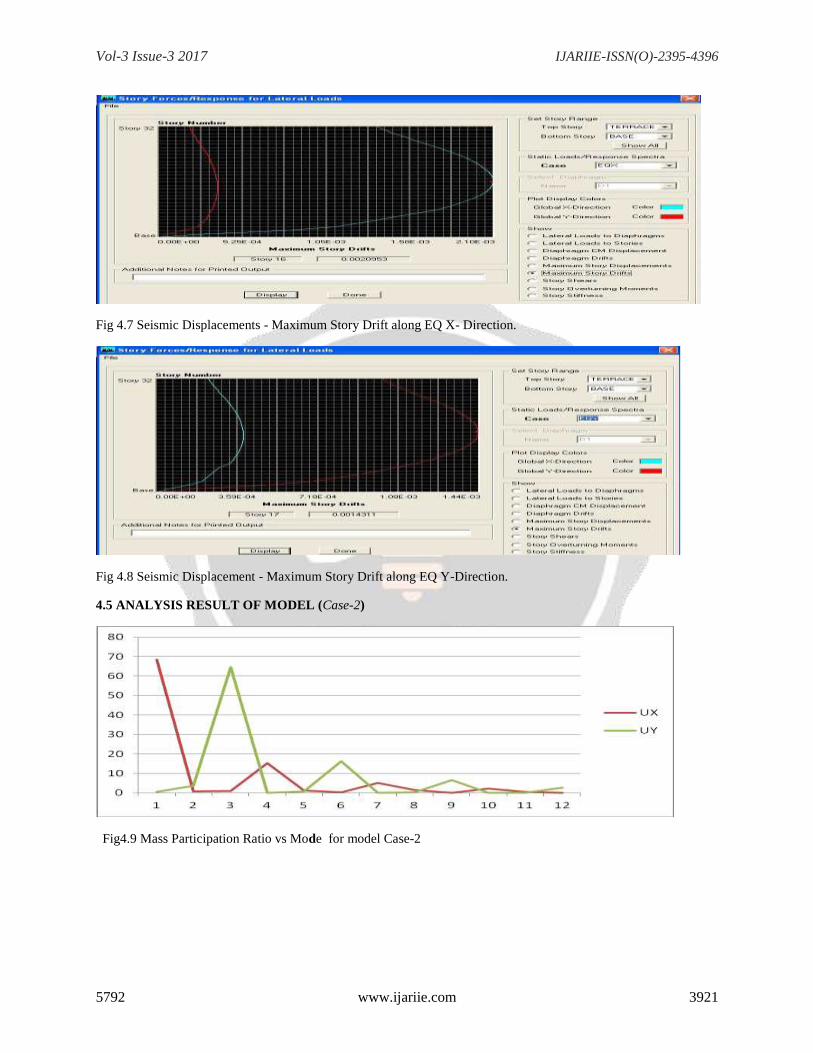
Fig 4.7 Seismic Displacements - Maximum Story Drift along EQ X- Direction.
Fig 4.8 Seismic Displacement - Maximum Story Drift along EQ Y-Direction.
4.5 ANALYSIS RESULT OF MODEL (Case-2)
Fig4.9 Mass Participation Ratio vs Mode for model Case-2

Vol-3 Issue-3 2017 IJARIIE-ISSN(O)-2395-4396
5792 www.ijariie.com 3922
Fig 4.10 Seismic Story shear –Story shear vs story for model Case-2
Fig 4.11: Seismic Base shear –Story shear vs story for model Case2-2
Fig 4.12 Response Spectrum Reaction vs mode shape (x & y- Direction)
4.6 Displacement-case 2

Vol-3 Issue-3 2017 IJARIIE-ISSN(O)-2395-4396
5792 www.ijariie.com 3923
Fig 4.13–Maximum Story Displacements along EQ X- Direction (Case-2 Unequal Equal Height)
Fig 4.14–Maximum Story Displacements along EQ Y- Direction (Case-2 Unequal Equal Height)
Fig 4.15 –Maximum Story Displacements along WL X- Direction (Case-2 Unequal Equal Height)
Fig 4.16–Maximum Story Displacements along WL Y- Direction (Case-2 Unequal Equal Height)

Vol-3 Issue-3 2017 IJARIIE-ISSN(O)-2395-4396
5792 www.ijariie.com 3924
4.7 Deflection
Model –M1 Equal Height
S+30 S+30
Max. Deflection(mm)
Permissible
Limit
Max. Deflection(mm)
Permissible
Limit
EQX 156.7939 364.8 EQX 156.7939 364.8
EQY 105.7987 364.8 EQY 105.7987 364.8
WLX 155.2225 182.4 WLX 155.2225 182.4
WLY 68.691 182.4 WLY 68.691 182.4
Model -M2 Unequal Height
S+25 S+30
Max. Deflection(mm)
Permissible
Limit
Max. Deflection(mm)
Permissible
Limit
EQX 120.1265 306.8 EQX 156.7939 364.8
EQY 82.9824 306.8 EQY 105.7987 364.8
WLX 77.6978 153.4 WLX 155.2225 182.4
WLY 44.559 153.4 WLY 68.691 182.4
4.8 Separation Gap
Model –M1 Equal Height G+30
IS1893-2000 IS4326-1993 FEMA-273(1997)
IBC-ASCE1997
EQX 627.17 547.2 221.74 313.5878
EQY 423.19 547.2 149.62 211.5878
Model -M2 Unequal Height G+25&G+30

Vol-3 Issue-3 2017 IJARIIE-ISSN(O)-2395-4396
5792 www.ijariie.com 3925
IS1893-2000 IS4326-1993 FEMA-273(1997)
IBC-ASCE1997
EQX 1107.6816 503.7 197.5214 313.5878
EQY 755.1252 503.7 134.4598 211.5878
Table 4.1: Separation distances from codes G+30 Equal Building
Code
Deflection
EQX 156.7939
Deflection
EQY 105.7987
Canada
313.5878
211.5974
Egypt
627.1756 OR 364.8
423.1948 OR 3364.8
Ethiopia
627.1756
423.1948
India
627.1756
423.1948
Peru
209.058 OR 365.8
141.049 OR 365.8
Code
Deflection
EQX 25 - 120.1265
EQX 30 -156.7939
Deflection
EQY25 - 82.9824
EQY30 - 105.7939
Canada
276.9204
188.7763

Vol-3 Issue-3 2017 IJARIIE-ISSN(O)-2395-4396
5792 www.ijariie.com 3926
Table 7.2: Separation distances from codes G+25 & G+30 Unequal Building
5. CONCLUSION
1. In general when the separation distance between the two structures decreases, the amount of impact is increases,
which is not in all cases.
2. Among all the codal provisions, the calculated separation distance is less for FEMA: 273-1997 and PeruE030-
2003. Because the clauses for these codes depends on height of the structure.
3. Equal height required less separation gap, Unequal height required more separation gap
4. Existing adjacent buildings which are not properly separated from each other can be protected from effects of
pounding by placing elastic materials between them.
5. The pounding effect can be decreased with increasing separation distance.
6. The pounding forces are also decreasing gradually between two adjacent buildings by introducing shear walls at
suitable locations
6. REFERANCES
1. Alireza M.Goltabar, R. Shamstabar Kami and A. Ebadi - Study of Impact between Adjacent Structures
during of Earthquake and their Effective Parameters
2. Anagnostopoulos, S. A. and Spiliopoulos, K.V. (1992), ‗An investigation of earthquake induced pounding
between adjacent buildings‘, Earthquake Engineering and Structural Dynamics, Vol. 21, pp. 289-302.
3. Thoms and others— 1964 Great Alaska Earthquake—A Photographic Tour of Anchorage, Alaska—
Open-File Report 2014–108 ISSN 2331-
4. Chenna Rajaram, ‗A Study of Pounding Between Adjacent Structures‘, A thesis submitted for the Degree
of MS, Earthquake Research Center, International Institute of Information Technology, Hyderabad, April
2011.
5. Shehata E. Abdel Raheem, ‗Seismic Pounding Between Adjacent Building Structures‘, Electronic Journal
of Structural Engineering, 6 (2006), Page No. 66.
6. Uemuet Goergulue & Nawawi Chouw, ‗Measures for Reducing The Effect of Pounding Between Adjacent
Buildings During Near-source Earthquakes‘.
7. Ishan Joyti Sharma, ‗Seismic Pounding Effect in Buildings‘, A thesis submitted for the Degree, Department
of Civil Engineering, NIT, Rourkela.
Egypt
553.839
377.5526
Ethiopia
553.839
377.5526
India
1107.6816
755.1052
Peru
184.6136
125.8508

Vol-3 Issue-3 2017 IJARIIE-ISSN(O)-2395-4396
5792 www.ijariie.com 3927
8. Robert Jankowski, ‗Earthquake-induced pounding Between Equal Height Buildings With Substantially
Different Dynamic Properties‘, Engineering Structures 30 (2008) 2818-2829, Science Direct, March 2008.
9. IS 1893 (Part 1) : 2002 Indian Standard ‗Criteria for Earthquake Resistant Design of Structures‘, Part 1
General Provisions and Buildings.
10. IS 456 : 2000 Indian Standard ‗Plain and Reinforced Concrete - Code of Practice‘.
11. SP 16 Design Aids for Reinforced Concrete
12. IS 875 (Part 2): 1987 Indian Standard ‗Code of Practice for Design Loads (Other Than Earthquake) for
Buildings and Structures‘, Part 2 Imposed Loads.
13. IS 4326-2005: 1993 ‗Indian Standard Code of Practice for Earthquake Resistant Design and Construction
of Building‘.
14. FEMA±273 [1997] ―NEHRP Guidelines for the seismic rehabilitation of buildings, Report
No.FEMA±273,‖ Federal Emergency Management Agency.
15. International building code (IBC) American society for civil engg. Seismic provision (ASCE 7-05)
16. CSI Analysis Reference Manual for E-tabs, Computers and Structures, Inc, Berkeley, California, USA,
2005.
BIOGRAPHIES
Shailesh Bharat Anantwad,
student:-
Masters of Engineering (civil), M. S.
Bidve college of Engineering, Latur.
Prof. V.G.PATWARI Assistant professor, Civil Engineering, M.S.Bidve College of Engineering, Latur.