studies on compressive failure features in syntactic foam material
TRANSCRIPT
J O U R N A L O F M A T E R I A L S S C I E N C E 3 6 (2 0 0 1 ) 4485 – 4491
Studies on compressive failure features in
syntactic foam material
N. GUPTA∗Department of Mechanical Engineering, Louisiana State University, Baton Rouge, LA 70803,USAE-mail: [email protected]
KISHOREDepartment of Metallurgy, Center for Advanced Studies, Polymer Composite Laboratory,Indian Institute of Science, Bangalore 560 012, India
E. WOLDESENBETDepartment of Mechanical Engineering, Louisiana State University, Baton Rouge, LA 70803,USA
S. SANKARANAeronautical Development Establishment, C.V. Raman Nagar, Bangalore 560 093, India
Syntactic foam made by mechanical mixing of glass hollow spheres in epoxy resin matrixis characterized for compressive properties in the present study. Volume fraction of hollowspheres in the syntactic foam under investigation is kept at 67.8%. Effect of specimenaspect ratio on failure behavior and stress-strain curve of the material is highlighted.Considerable differences are noted in the macroscopic fracture features of the specimenand the stress-strain curve with the variation in specimen aspect ratio, althoughcompressive yield strength values were within a narrow range. Post compression testscanning electron microscopic observations coupled with the macroscopic observationstaken during the test helped in explaining the deviation in specimen behavior and ingathering support for the proposed arguments. C© 2001 Kluwer Academic Publishers
1. IntroductionDeveloped in early 60’s as buoyancy-aid materials fordeep-sea applications [1], syntactic foams soon gainedattention of aeronautical sector due to their superiorcompressive properties and adaptability to many situ-ations through the use of various reinforcements andfiller materials. The possibilities of making wide rangeof densities including the very low value bearing onesare the key to these materials gaining increasing atten-tion. Among other properties low radar detectabilityand low moisture absorption [2] open a route for thesematerials for structural applications in the aeronauticalsector. Depending upon raw materials and the composi-tion, it is possible to manufacture syntactic foams hav-ing compressive yield strength between 10 to 100 MPaand density range from 150 to over 1000 kg/cm3.
Due to the presence of hollow spheres in the syn-tactic foam structure, porosity is present in the closedcell form. The hollow spheres may be made up of met-als, polymers or ceramics [3]. Similarly several typesof polymers are used as matrix resin [4]. If the hol-low spheres are incorporated to the maximum possiblevolume fraction, they are expected to assume a close
∗ Author to whom all correspondence should be addressed.
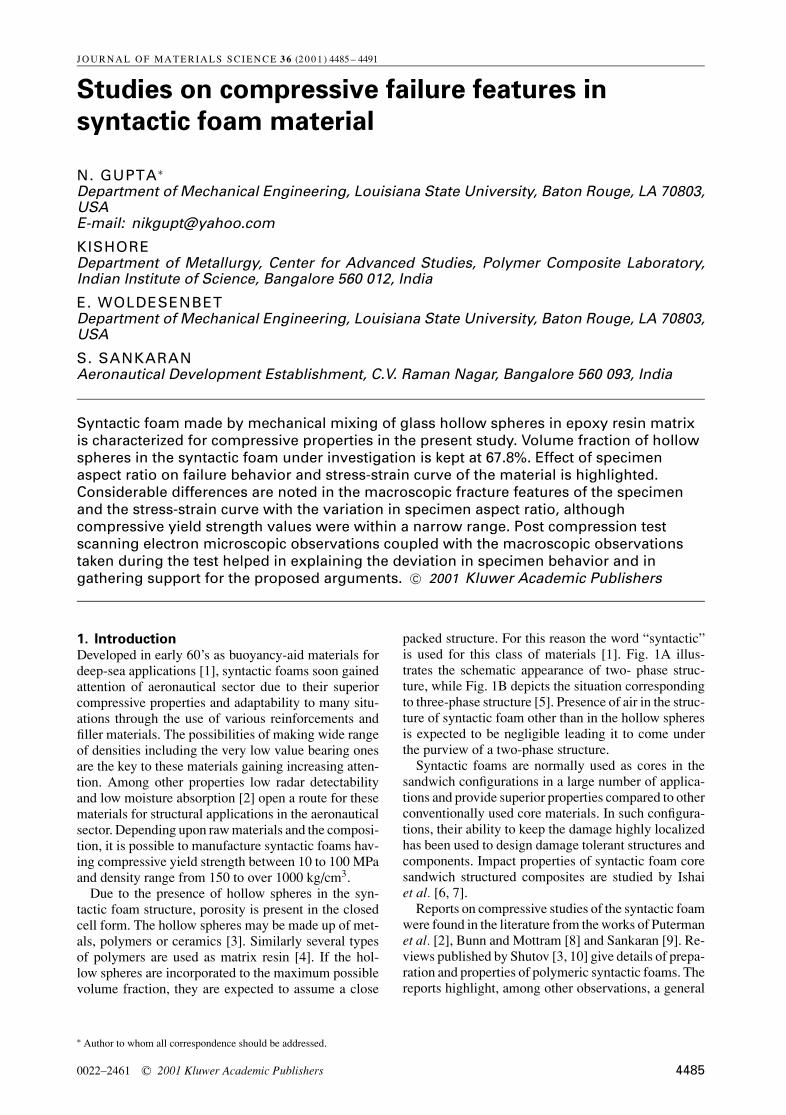
packed structure. For this reason the word “syntactic”is used for this class of materials [1]. Fig. 1A illus-trates the schematic appearance of two- phase struc-ture, while Fig. 1B depicts the situation correspondingto three-phase structure [5]. Presence of air in the struc-ture of syntactic foam other than in the hollow spheresis expected to be negligible leading it to come underthe purview of a two-phase structure.
Syntactic foams are normally used as cores in thesandwich configurations in a large number of applica-tions and provide superior properties compared to otherconventionally used core materials. In such configura-tions, their ability to keep the damage highly localizedhas been used to design damage tolerant structures andcomponents. Impact properties of syntactic foam coresandwich structured composites are studied by Ishaiet al. [6, 7].
Reports on compressive studies of the syntactic foamwere found in the literature from the works of Putermanet al. [2], Bunn and Mottram [8] and Sankaran [9]. Re-views published by Shutov [3, 10] give details of prepa-ration and properties of polymeric syntactic foams. Thereports highlight, among other observations, a general
0022–2461 C© 2001 Kluwer Academic Publishers 4485
(A)
(B)
Figure 1 Schematic showing the features in (a) two phase and (b) threephase structures in a syntactic foam material.
stress-strain curve for a low hollow sphere volume frac-tion bearing syntactic foam system. In the present studystress is laid on analyzing the compressive properties ofhigh hollow sphere volume fraction bearing two-phasesyntactic foam system. Volume fraction of glass hollowspheres in the fabricated syntactic foam slabs was main-tained at 74%. Further on, compressive properties withrespect to the aspect ratio (height/width ratio) of thetest specimens were looked into. The investigation wascarried out with an aim of looking at the deformationand fracture features of syntactic foam specimens in thecompressive loading conditions, shape of stress–straincurve and compressive strength values arising fromalteration in aspect ratio of the specimen. Attempts havebeen made to correlate the different factors at variousstages of compression testing.
2. MaterialsThe raw materials used to fabricate syntactic foamwere glass hollow spheres (microballoons) as closedpore material and epoxy resin as matrix system. Glassmicroballoons supplied by Grace Electronic Materials(Belgium) had an average particle diameter of 80 µmand bulk density of 254 kg/m3. Glass microballoon par-ticle size distribution and compressive strength valuesprovided by the supplier are given in Tables I and IIrespectively. Low temperature curing epoxy resin (LY
T ABL E I Particle size distribution of glass microballoons
No. Particle size range (µm) Weight fraction
1 149–175 0.142 125–149 0.103 100–125 0.124 44–100 0.555 <44 0.09
TABLE I I Crushing strength of glass microballoons
No. Stress level (MPa) % Collapse
1 3.4 142 6.9 323 13.8 554 20.7 75
5052) with the hardener (HY 5052), manufactured byCiba-Geigy was used as the matrix material. Resin sys-tem had a density of 1100 kg/m3. Resin and hardenerwere mixed together in the ratio of 100:38 by weight.For the fabrication of syntactic foam slabs, resin systemto microballoon ratio of 1.52:1 by weight was taken,which is 74.0% microballoons and 26.0% resin by vol-ume. Density of the foam slabs was 433 kg/m3 with avariation of 0.18% among the various slabs. Averagevoid content (open cell porosity) in the foam slab was8.4% by volume, with a variation of 0.2% among vari-ous foam slabs. Through careful and extensive scanningelectron microscopy it was observed that the voids wereevenly distributed in the structure. Due to the voids inthe structure the final volume fractions of the materialsin the syntactic foam slabs can be given as: resin 23.8%,microballoons 67.8% and voids 8.4%. Through a care-ful processing schedule and repetition of experiments,the above cited value for the void content was found tobe the minimal approachable for the given combinationof materials and the processing parameters.
Syntactic foam was cast as slabs in the mold of di-mensions measuring 150×150×25.4 mm3 by unpres-surized casting. Foam slabs were cured for 18 hrs atambient temperature and then post cured at 130 ± 3◦Cfor 2 1/2 hrs.
3. Test parametersA 100 KN DARTEC-9500 servo-hydraulic micropro-cessor controlled machine was used for carrying outthe compression tests. True strain rate of 0.01 s−1
was maintained throughout the test. Load vs. displace-ment data plots obtained from the test were used for theanalysis.
Based on the cellular structure of the materials,ASTM D1621 [11] test standard was considered to besuitable for compression tests. In order to investigatethe effect of specimen aspect ratio on the compres-sive test results, several aspect ratio values were takenwithin the range recommended in this ASTM standard.A smaller than ASTM recommended specimen cross-section area specimens were fabricated and tested. Thisis justified by the fact that the average cell size in thematerial is 80 microns and about 75% of the microbal-loons had size less than 125 microns, hence over 75cells would be present in the smallest dimension of anyof the test specimens, which is 10 mm. Due to presenceof large number of cells in the specimen in any givendirection the effect of localized phenomena, if any, isexpected to be negligible. The characterization of syn-tactic foam for the mechanical data with respect to thespecimen aspect ratio has not been found explored in theliterature.
4486
T ABL E I I I Values of compressive yield strength for the syntacticfoam specimens
Dimensions (mm) Compressive yieldSpecimen type h × l × b∗ Aspect satio strength (MPa)
A 10 × 11 × 11 0.91 22.4B 10 × 15 × 15 0.67 20.5C 6.0 × 10 × 10 0.6 19.7D 10 × 25 × 25 0.4 20.9
∗h, l and b are height, length and width of the specimens respectively.
4. ExperimentalSquare cross section area specimens were preparedfrom the cast foam slabs for testing. Specimens havingfour different aspect ratios 0.91, 0.67, 0.6 and 0.4 werefabricated for compression testing. Dimensions of allthe specimens tested in this study are given in Table III.Variations in the measurements of the dimensions ofthe specimens were kept below the ASTM standardrecommended value of 1%.
In order to make this characterization study morecomplete, the behavior of the specimen and the oc-currence of various events during the test were care-fully monitored. Tests were continued well beyond theminimum recommended compression value, which is13% or the appearance of yield point. Compressiveyield strength was measured for every specimen. Forthe specimens that did not show a distinct yield point,tangents were drawn to the linear portions of elasticregion and plastic region of the curve. The intersectionpoint of these tangents was taken as the yield point forthat specimen.
5. Results and discussionFor the syntactic foam material under investigation inthe present study the test standard ASTM D 1621-94 isconsidered suitable. In an earlier study of low microbal-loon volume fraction syntactic foams [8], the specimenshaving aspect ratio of 2 were tested according to the teststandard ASTM D 695-91 [12]. For low volume frac-tion of the microballoons, the characteristics of epoxyresin matrix prevail and this standard, which is for com-pression testing of rigid plastics, can be followed. Athigher volume fraction of microballoons the syntacticfoam material behaves like a cellular material havingcell size equal to the size of microballoons. Hence, thestandard ASTM D 1621-94, which is specifically forcellular structured rigid plastics, is followed. It is ofrelevance to note that with total porosity figure (openand closed porosity combined) being as high as 76%,specimens having aspect ratio value of 1 or higher dis-play difficulties in uniform compression. This is due tothe formation of powdery and loose mass at the regionwhere crack originated in the early stages of compres-sion, which later on leads to the separation of fragmentsfrom the material around the path of the crack. For thisreason it was decided not to try out aspect ratios of 1 forthe studies and the maximum value of aspect ratio wasset at 0.91. The values of specimen aspect ratios takenin this study are in the range recommended by ASTM D1621-94. Justification for taking smaller cross-section
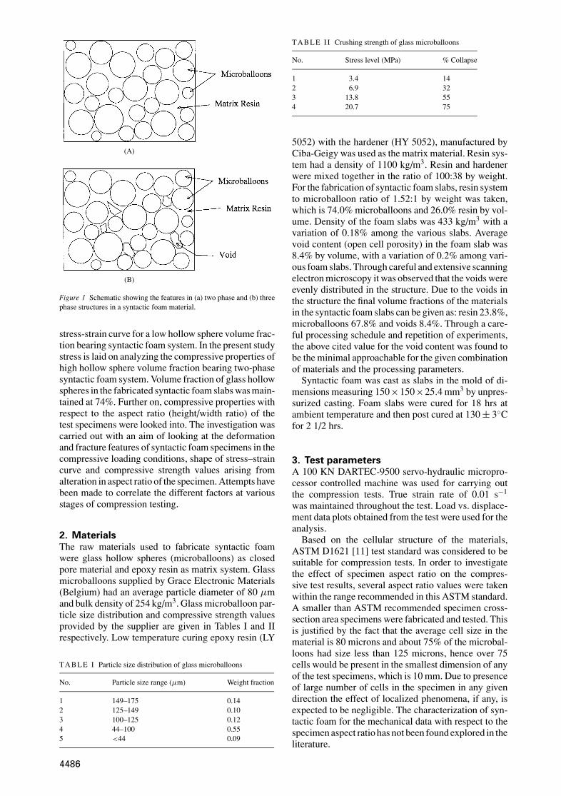
Figure 2 Load-displacement curve for high aspect ratio (0.91) syntacticfoam specimen as obtained during the compression test.
area than the recommended values is given in test pa-rameters sections.
An actual load-displacement curve obtained in thecompression testing of the specimen having aspect ra-tio of 0.91 is shown if Fig. 2. A generalized schematiccurve for the specimens having the higher side of val-ues for aspect ratio (viz., 0.91 and 0.67) is shown inFig. 3, where a distinct yield point at the end of elasticregion could be noted. The decrease in the load at thispoint was of the order of about 15 to 20% of the peakload. This curve is divided into three distinct regions.Region 1 showing linear trend corresponds to the elas-tic behavior of the foam. At the end of the region 1, ayield point is seen and the load becomes nearly constantafter a slight decrease, which is termed as region 2 orplateau region. At the end of the second region stressagain starts increasing. Plateau region corresponds tothe energy absorption in the process of crushing ofmicroballoons. Hollow space exposed by the fractureof microballoons is consumed by the materials whilegetting compressed. When a significant fraction of mi-croballoons gets crushed, further increase in the loadresults in the densification of the foam and is visibleas an upward trend in the curve. Similar observationswere made by Bunn and Mottram [8] also. On thecontrary, the specimens having a lower value of as-pect ratio, namely 0.6, did not display this decrease instress after the maximum value. Stress becomes nearly
Figure 3 Generalized stress-strain curve for high aspect ratio bearingsyntactic foam specimens.
4487
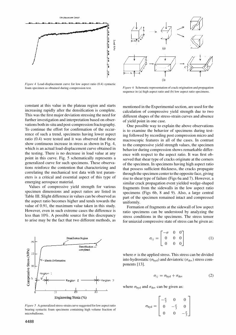
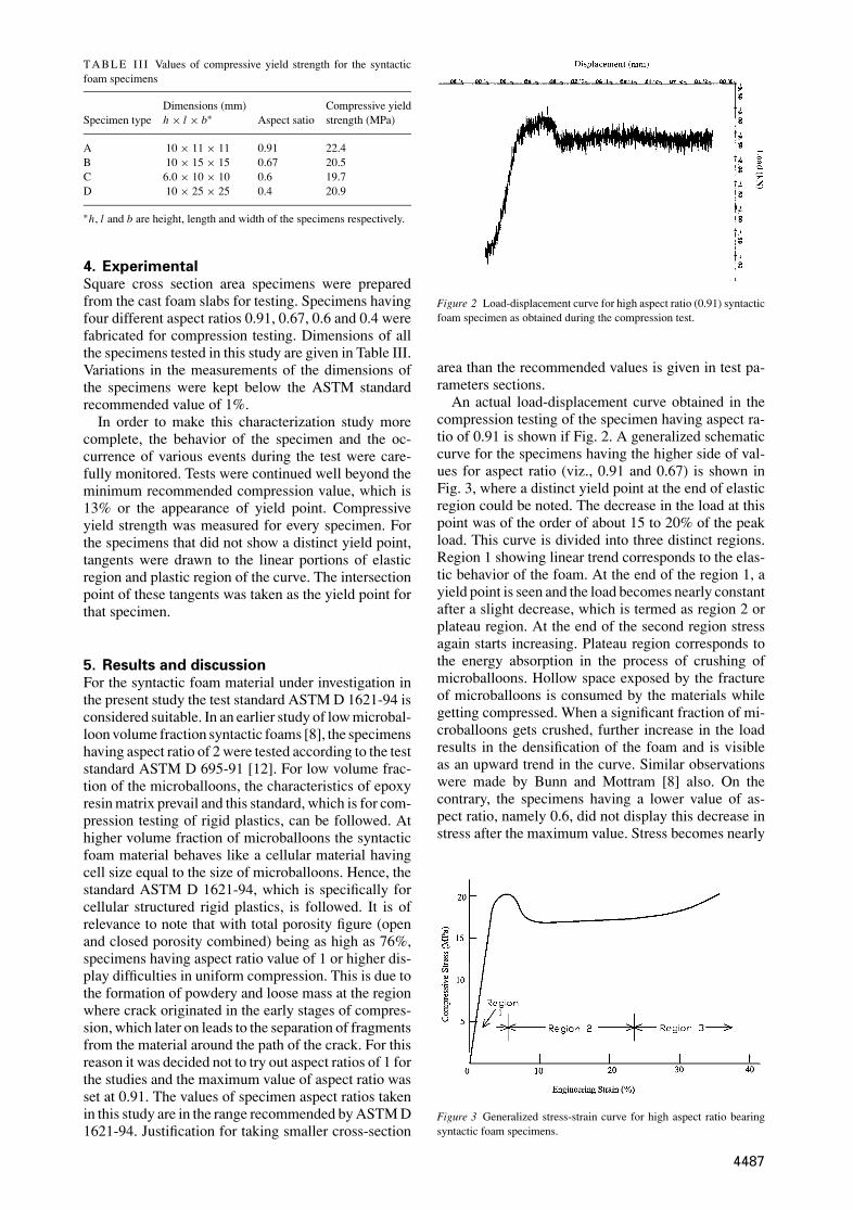
Figure 4 Load-displacement curve for low aspect ratio (0.4) syntacticfoam specimen as obtained during compression test.
constant at this value in the plateau region and startsincreasing rapidly after the densification is complete.This was the first major deviation stressing the need forfurther investigation and interpretation based on obser-vations both in-situ and post-compression fractography.To continue the effort for confirmation of the occur-rence of such a trend, specimens having lower aspectratio (0.4) were tested and it was observed that theseshow continuous increase in stress as shown in Fig. 4,which is an actual load-displacement curve obtained inthe testing. There is no decrease in load value at anypoint in this curve. Fig. 5 schematically represents ageneralized curve for such specimens. These observa-tions reinforce the contention that characterizing andcorrelating the mechanical test data with test param-eters is a critical and essential aspect of this type ofemerging aerospace material.
Values of compressive yield strength for variousspecimen dimensions and aspect ratios are listed inTable III. Slight difference in values can be observed asthe aspect ratio becomes higher and tends towards thevalue of 0.91, the maximum value taken in this study.However, even in such extreme cases the difference isless than 10%. A possible source for this discrepancyto arise may be the fact that two different methods, as
Figure 5 A generalized stress-strain curve suggested for low aspect ratiobearing syntactic foam specimens containing high volume fraction ofmicroballoons.
Figure 6 Schematic representation of crack origination and propagationsequence in (a) high aspect ratio and (b) low aspect ratio specimens.
mentioned in the Experimental section, are used for thecalculation of compressive yield strength due to twodifferent shapes of the stress-strain curves and absenceof yield point in one case.
One possible way to explain the above observationsis to examine the behavior of specimens during test-ing followed by recording post compression micro andmacroscopic features in all of the cases. In contrastto the compressive yield strength values, the specimenbehavior during compression shows remarkable differ-ence with respect to the aspect ratio. It was first ob-served that shear type of cracks originate at the cornersof the specimen. In specimens having high aspect ratiothat possess sufficient thickness, the cracks propagatethrough the specimen center to the opposite face, givingrise to shear type of failure (Figs 6a and 7). However, asimilar crack propagation event yielded wedge-shapedfragments from the sidewalls in the low aspect ratiospecimens (Figs 6b, 8 and 9). Also, a large centralpart of the specimen remained intact and compresseduniformly.
Formation of fragments at the sidewall of low aspectratio specimens can be understood by analyzing thestress conditions in the specimens. The stress tensorfor uniaxial compressive state of stress can be given as:
σi j =
−σ 0 00 0 00 0 0
(1)
where σ is the applied stress. This stress can be dividedinto hydrostatic (σhyd) and deviatoric (σdev) stress com-ponents [13].
σi j = σhyd + σdev (2)
where σhyd and σdev can be given as:
σhyd =
−σ3 0 0
0 −σ3 0
0 0 −σ3
4488
(a)
(b)
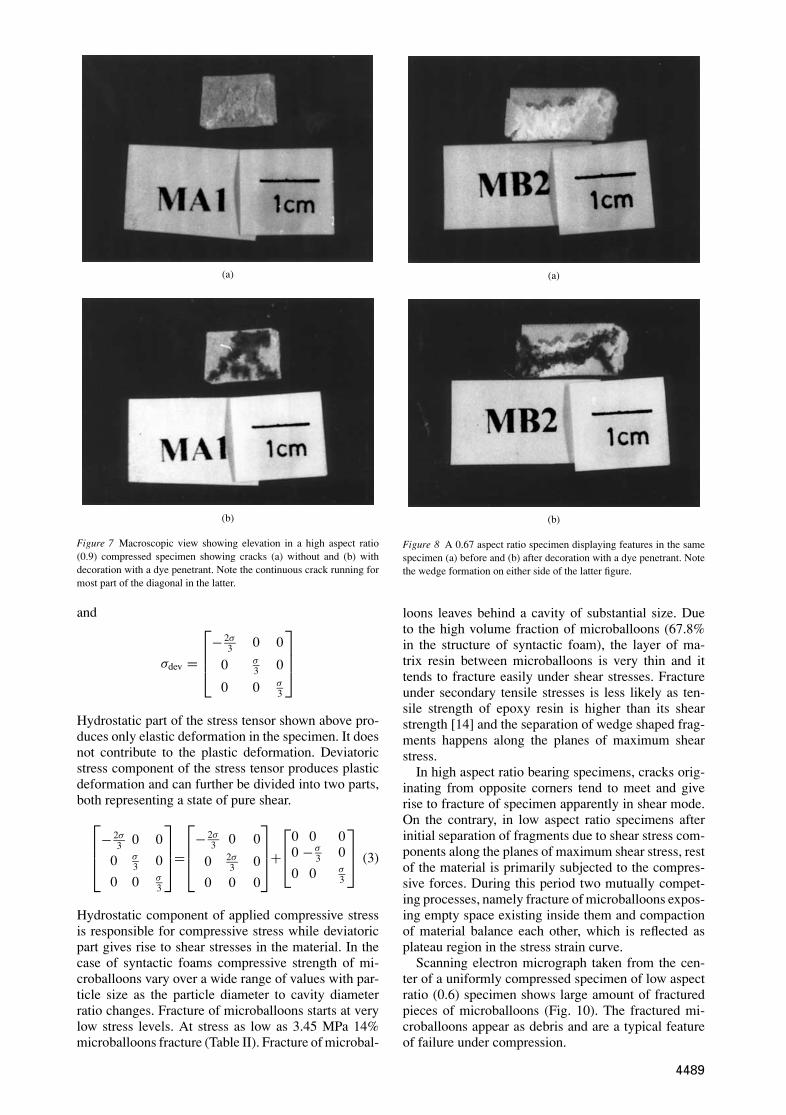
Figure 7 Macroscopic view showing elevation in a high aspect ratio(0.9) compressed specimen showing cracks (a) without and (b) withdecoration with a dye penetrant. Note the continuous crack running formost part of the diagonal in the latter.
and
σdev =
− 2σ3 0 0
0 σ3 0
0 0 σ3
Hydrostatic part of the stress tensor shown above pro-duces only elastic deformation in the specimen. It doesnot contribute to the plastic deformation. Deviatoricstress component of the stress tensor produces plasticdeformation and can further be divided into two parts,both representing a state of pure shear.
− 2σ3 0 0
0 σ3 0
0 0 σ3
=
− 2σ3 0 0
0 2σ3 0
0 0 0
+
0 0 00 −σ
3 0
0 0 σ3
(3)
Hydrostatic component of applied compressive stressis responsible for compressive stress while deviatoricpart gives rise to shear stresses in the material. In thecase of syntactic foams compressive strength of mi-croballoons vary over a wide range of values with par-ticle size as the particle diameter to cavity diameterratio changes. Fracture of microballoons starts at verylow stress levels. At stress as low as 3.45 MPa 14%microballoons fracture (Table II). Fracture of microbal-
(a)
(b)
Figure 8 A 0.67 aspect ratio specimen displaying features in the samespecimen (a) before and (b) after decoration with a dye penetrant. Notethe wedge formation on either side of the latter figure.
loons leaves behind a cavity of substantial size. Dueto the high volume fraction of microballoons (67.8%in the structure of syntactic foam), the layer of ma-trix resin between microballoons is very thin and ittends to fracture easily under shear stresses. Fractureunder secondary tensile stresses is less likely as ten-sile strength of epoxy resin is higher than its shearstrength [14] and the separation of wedge shaped frag-ments happens along the planes of maximum shearstress.
In high aspect ratio bearing specimens, cracks orig-inating from opposite corners tend to meet and giverise to fracture of specimen apparently in shear mode.On the contrary, in low aspect ratio specimens afterinitial separation of fragments due to shear stress com-ponents along the planes of maximum shear stress, restof the material is primarily subjected to the compres-sive forces. During this period two mutually compet-ing processes, namely fracture of microballoons expos-ing empty space existing inside them and compactionof material balance each other, which is reflected asplateau region in the stress strain curve.
Scanning electron micrograph taken from the cen-ter of a uniformly compressed specimen of low aspectratio (0.6) specimen shows large amount of fracturedpieces of microballoons (Fig. 10). The fractured mi-croballoons appear as debris and are a typical featureof failure under compression.
4489
(a)
(b)
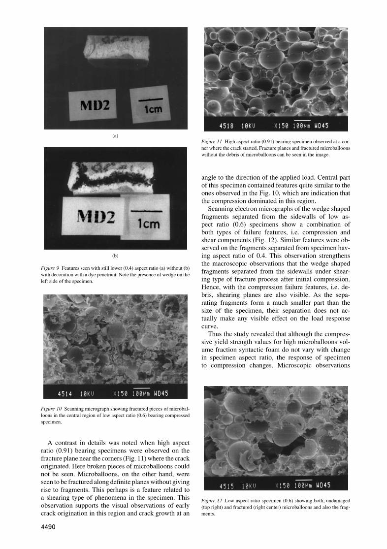
Figure 9 Features seen with still lower (0.4) aspect ratio (a) without (b)with decoration with a dye penetrant. Note the presence of wedge on theleft side of the specimen.
Figure 10 Scanning micrograph showing fractured pieces of microbal-loons in the central region of low aspect ratio (0.6) bearing compressedspecimen.
A contrast in details was noted when high aspectratio (0.91) bearing specimens were observed on thefracture plane near the corners (Fig. 11) where the crackoriginated. Here broken pieces of microballoons couldnot be seen. Microballoons, on the other hand, wereseen to be fractured along definite planes without givingrise to fragments. This perhaps is a feature related toa shearing type of phenomena in the specimen. Thisobservation supports the visual observations of earlycrack origination in this region and crack growth at an
Figure 11 High aspect ratio (0.91) bearing specimen observed at a cor-ner where the crack started. Fracture planes and fractured microballoonswithout the debris of microballoons can be seen in the image.
angle to the direction of the applied load. Central partof this specimen contained features quite similar to theones observed in the Fig. 10, which are indication thatthe compression dominated in this region.
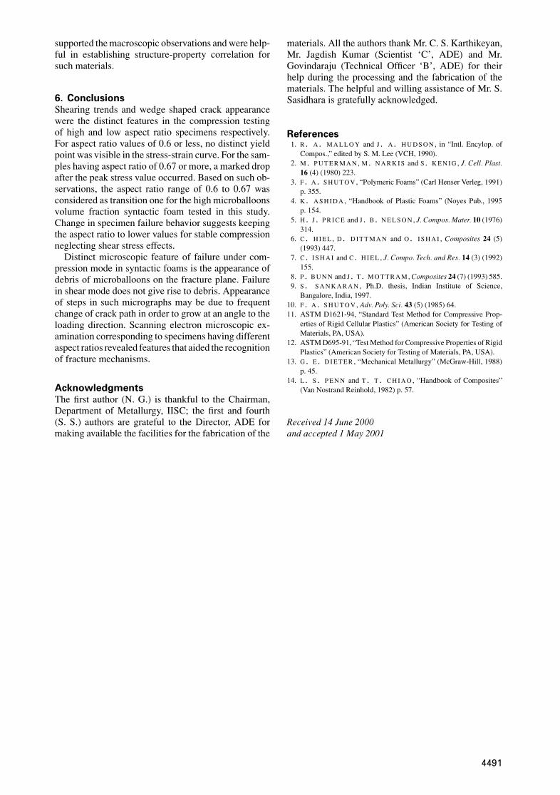
Scanning electron micrographs of the wedge shapedfragments separated from the sidewalls of low as-pect ratio (0.6) specimens show a combination ofboth types of failure features, i.e. compression andshear components (Fig. 12). Similar features were ob-served on the fragments separated from specimen hav-ing aspect ratio of 0.4. This observation strengthensthe macroscopic observations that the wedge shapedfragments separated from the sidewalls under shear-ing type of fracture process after initial compression.Hence, with the compression failure features, i.e. de-bris, shearing planes are also visible. As the sepa-rating fragments form a much smaller part than thesize of the specimen, their separation does not ac-tually make any visible effect on the load responsecurve.
Thus the study revealed that although the compres-sive yield strength values for high microballoons vol-ume fraction syntactic foam do not vary with changein specimen aspect ratio, the response of specimento compression changes. Microscopic observations
Figure 12 Low aspect ratio specimen (0.6) showing both, undamaged(top right) and fractured (right center) microballoons and also the frag-ments.
4490
supported the macroscopic observations and were help-ful in establishing structure-property correlation forsuch materials.
6. ConclusionsShearing trends and wedge shaped crack appearancewere the distinct features in the compression testingof high and low aspect ratio specimens respectively.For aspect ratio values of 0.6 or less, no distinct yieldpoint was visible in the stress-strain curve. For the sam-ples having aspect ratio of 0.67 or more, a marked dropafter the peak stress value occurred. Based on such ob-servations, the aspect ratio range of 0.6 to 0.67 wasconsidered as transition one for the high microballoonsvolume fraction syntactic foam tested in this study.Change in specimen failure behavior suggests keepingthe aspect ratio to lower values for stable compressionneglecting shear stress effects.
Distinct microscopic feature of failure under com-pression mode in syntactic foams is the appearance ofdebris of microballoons on the fracture plane. Failurein shear mode does not give rise to debris. Appearanceof steps in such micrographs may be due to frequentchange of crack path in order to grow at an angle to theloading direction. Scanning electron microscopic ex-amination corresponding to specimens having differentaspect ratios revealed features that aided the recognitionof fracture mechanisms.
AcknowledgmentsThe first author (N. G.) is thankful to the Chairman,Department of Metallurgy, IISC; the first and fourth(S. S.) authors are grateful to the Director, ADE formaking available the facilities for the fabrication of the
materials. All the authors thank Mr. C. S. Karthikeyan,Mr. Jagdish Kumar (Scientist ‘C’, ADE) and Mr.Govindaraju (Technical Officer ‘B’, ADE) for theirhelp during the processing and the fabrication of thematerials. The helpful and willing assistance of Mr. S.Sasidhara is gratefully acknowledged.
References1. R . A . M A L L O Y and J . A . H U D S O N , in “Intl. Encylop. of
Compos.,” edited by S. M. Lee (VCH, 1990).2. M. P U T E R M A N , M. N A R K I S and S . K E N I G , J. Cell. Plast.
16 (4) (1980) 223.3. F . A . S H U T O V , “Polymeric Foams” (Carl Henser Verleg, 1991)
p. 355.4. K . A S H I D A , “Handbook of Plastic Foams” (Noyes Pub., 1995
p. 154.5. H . J . P R I C E and J . B . N E L S O N , J. Compos. Mater. 10 (1976)
314.6. C . H I E L , D . D I T T M A N and O. I S H A I , Composites 24 (5)
(1993) 447.7. C . I S H A I and C. H I E L , J. Compo. Tech. and Res. 14 (3) (1992)
155.8. P . B U N N and J . T . M O T T R A M , Composites 24 (7) (1993) 585.9. S . S A N K A R A N , Ph.D. thesis, Indian Institute of Science,
Bangalore, India, 1997.10. F . A . S H U T O V , Adv. Poly. Sci. 43 (5) (1985) 64.11. ASTM D1621-94, “Standard Test Method for Compressive Prop-
erties of Rigid Cellular Plastics” (American Society for Testing ofMaterials, PA, USA).
12. ASTM D695-91, “Test Method for Compressive Properties of RigidPlastics” (American Society for Testing of Materials, PA, USA).
13. G . E . D I E T E R , “Mechanical Metallurgy” (McGraw-Hill, 1988)p. 45.
14. L . S . P E N N and T . T . C H I A O , “Handbook of Composites”(Van Nostrand Reinhold, 1982) p. 57.
Received 14 June 2000and accepted 1 May 2001
4491