stryker hand plating system · stryker hand operative technique • variax hand locking plate...
TRANSCRIPT
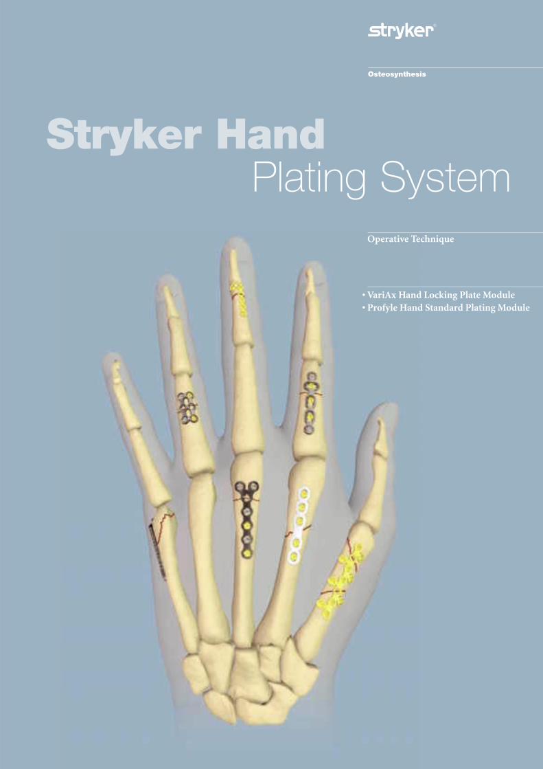
Stryker Hand
Operative Technique
• VariAx Hand Locking Plate Module• Profyle Hand Standard Plating Module
Plating System
2
Stryker Hand Plating System
Indications
•Intended for use in internal fixation of small bones including the hand and wrist.
Contraindications
•Inadequate bone quantity.
•Patients with active infections.
•Patients with metal allergies andforeign body sensitivity.
•Severely non-compliant patients with mental or neurologicalconditions who are unwilling orincapable of following postoperativecare instructions.
•Patients with limited blood supply
•Patients with unstable physical and/ormental health conditions.
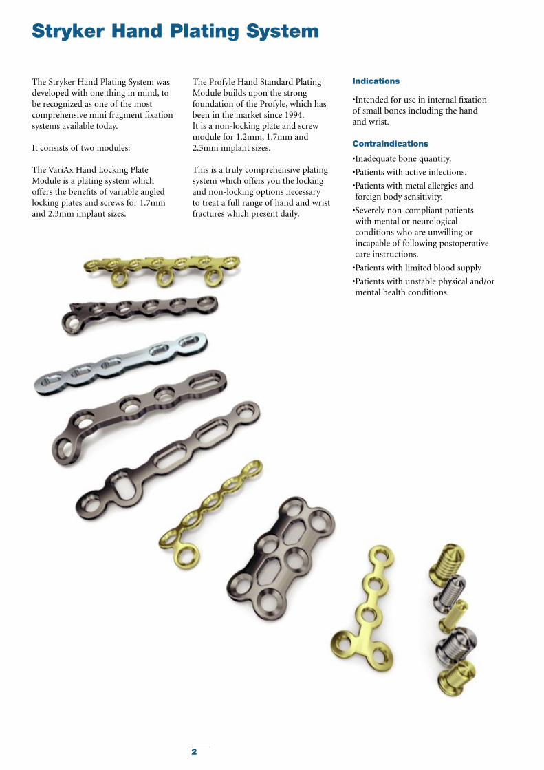
The Stryker Hand Plating System wasdeveloped with one thing in mind, tobe recognized as one of the mostcomprehensive mini fragment fixationsystems available today.
It consists of two modules:
The VariAx Hand Locking PlateModule is a plating system whichoffers the benefits of variable angledlocking plates and screws for 1.7mmand 2.3mm implant sizes.
The Profyle Hand Standard PlatingModule builds upon the strongfoundation of the Profyle, which hasbeen in the market since 1994.It is a non-locking plate and screwmodule for 1.2mm, 1.7mm and2.3mm implant sizes.
This is a truly comprehensive platingsystem which offers you the lockingand non-locking options necessary to treat a full range of hand and wristfractures which present daily.
3
Features & Benefits
Offers many choices to treat virtuallyany fracture.
Less need for bending, which mayreduce OR time.
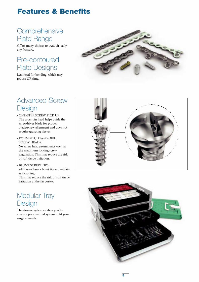
• ONE-STEP SCREW PICK UP.The cross pin head helps guide thescrewdriver blade for properblade/screw alignment and does notrequire grasping sleeves.
• ROUNDED, LOW-PROFILE SCREW HEADS.No screw head prominence even atthe maximum locking screwangulation. This may reduce the riskof soft tissue irritation.
• BLUNT SCREW TIPS.All screws have a blunt tip and remainself tapping.This may reduce the risk of soft tissueirritation at the far cortex.
ComprehensivePlate Range
Pre-contouredPlate Designs
Advanced ScrewDesign
The storage system enables you tocreate a personalized system to fit yoursurgical needs.
Modular TrayDesign
4
Features & Benefits
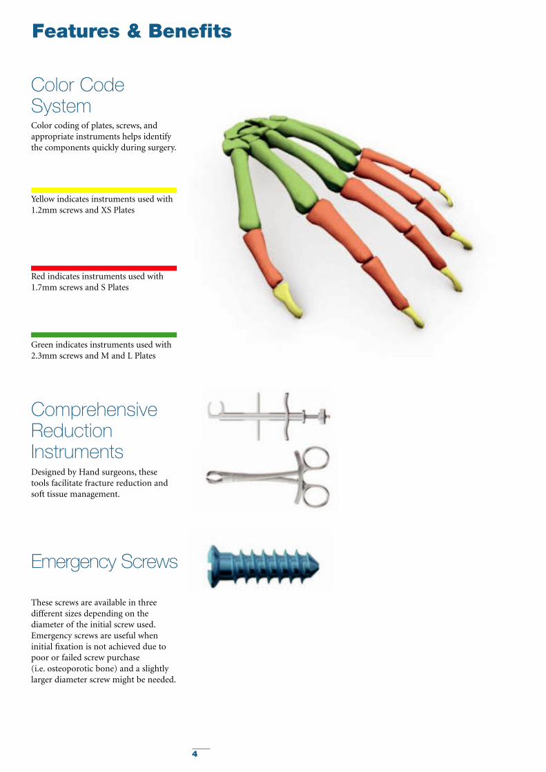
Color coding of plates, screws, andappropriate instruments helps identifythe components quickly during surgery.
Yellow indicates instruments used with1.2mm screws and XS Plates
Red indicates instruments used with1.7mm screws and S Plates
Green indicates instruments used with2.3mm screws and M and L Plates
Color CodeSystem
Designed by Hand surgeons, thesetools facilitate fracture reduction andsoft tissue management.
ComprehensiveReductionInstruments
Emergency Screws
These screws are available in threedifferent sizes depending on thediameter of the initial screw used.Emergency screws are useful wheninitial fixation is not achieved due topoor or failed screw purchase (i.e. osteoporotic bone) and a slightlylarger diameter screw might be needed.
5
Operative Technique
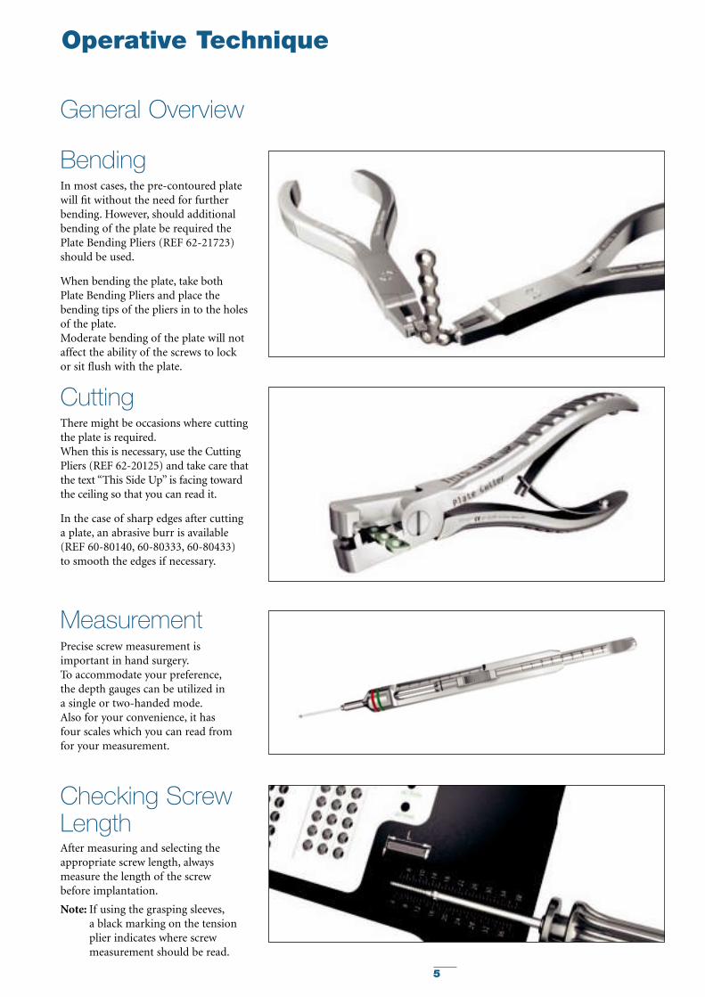
BendingIn most cases, the pre-contoured platewill fit without the need for furtherbending. However, should additionalbending of the plate be required thePlate Bending Pliers (REF 62-21723)should be used.
When bending the plate, take bothPlate Bending Pliers and place thebending tips of the pliers in to the holesof the plate.Moderate bending of the plate will notaffect the ability of the screws to lockor sit flush with the plate.
CuttingThere might be occasions where cuttingthe plate is required.When this is necessary, use the CuttingPliers (REF 62-20125) and take care thatthe text “This Side Up” is facing towardthe ceiling so that you can read it.
In the case of sharp edges after cuttinga plate, an abrasive burr is available(REF 60-80140, 60-80333, 60-80433) to smooth the edges if necessary.
General Overview
Precise screw measurement isimportant in hand surgery.To accommodate your preference,the depth gauges can be utilized in a single or two-handed mode.Also for your convenience, it has four scales which you can read fromfor your measurement.
Measurement
After measuring and selecting theappropriate screw length, alwaysmeasure the length of the screw before implantation.
Checking ScrewLength
Note: If using the grasping sleeves,a black marking on the tensionplier indicates where screwmeasurement should be read.
6
VariAx Hand Locking Plate Module
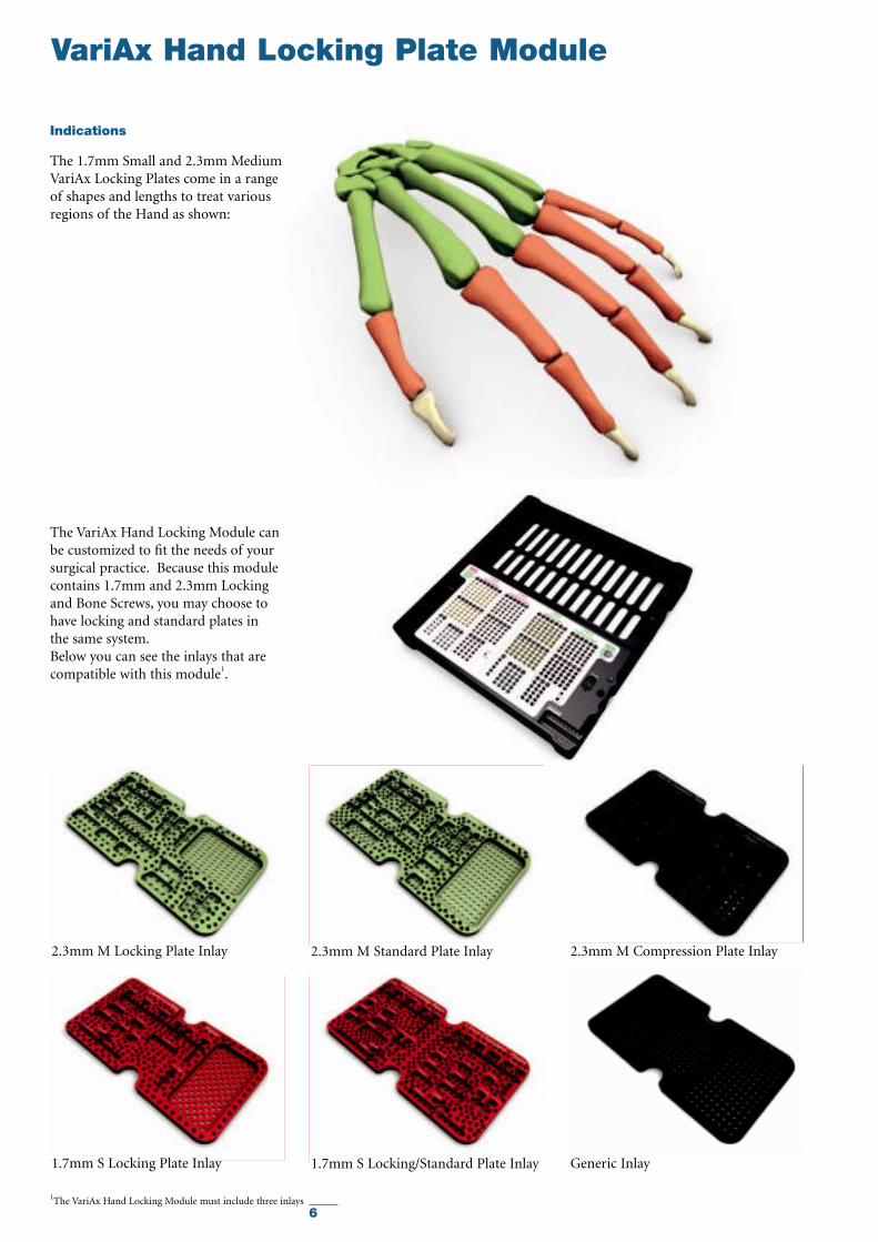
The VariAx Hand Locking Module canbe customized to fit the needs of yoursurgical practice. Because this modulecontains 1.7mm and 2.3mm Lockingand Bone Screws, you may choose tohave locking and standard plates in the same system.Below you can see the inlays that arecompatible with this module1.
1The VariAx Hand Locking Module must include three inlays
Indications
The 1.7mm Small and 2.3mm MediumVariAx Locking Plates come in a rangeof shapes and lengths to treat variousregions of the Hand as shown:
2.3mm M Locking Plate Inlay 2.3mm M Standard Plate Inlay 2.3mm M Compression Plate Inlay
1.7mm S Locking Plate Inlay 1.7mm S Locking/Standard Plate Inlay Generic Inlay
7
VariA
xH
and
Lockin
g P
late
Module
Features & Benefits
Type II Anodization
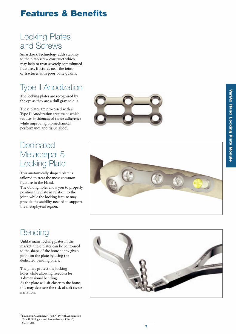
DedicatedMetacarpal 5Locking Plate
The locking plates are recognized bythe eye as they are a dull gray colour.
These plates are processed with a Type II Anodization treatment whichreduces incidences of tissue adherencewhile improving biomechanicalperformance and tissue glide2.
This anatomically shaped plate istailored to treat the most commonfracture in the Hand.The oblong holes allow you to properlyposition the plate in relation to thejoint, while the locking feature mayprovide the stability needed to supportthe metaphyseal region.
2 Baumann A., Zander, N. “Ti6A14V with Anodization Type II: Biological and Biomechanical Effects”,March 2005
Locking Plates and ScrewsSmartLock Technology adds stability to the plate/screw construct which may help to treat severely comminutedfractures, fractures near the joint,or fractures with poor bone quality.
BendingUnlike many locking plates in themarket, these plates can be contouredto the shape of the bone at any givenpoint on the plate by using thededicated bending pliers.
The pliers protect the locking holes while allowing freedom for 3 dimensional bending.As the plate will sit closer to the bone,this may decrease the risk of soft tissueirritation.
8
Features & Benefits
3Oblong holes do not lock 4The SmartLock Technology is patented (US 6, 322, 562; DE 43 43 117) by Professor Dietmar Wolter, Hamburg Germany
Locking orNonLocking – You Choose
SmartLockTechnology
SmartLockTechnology
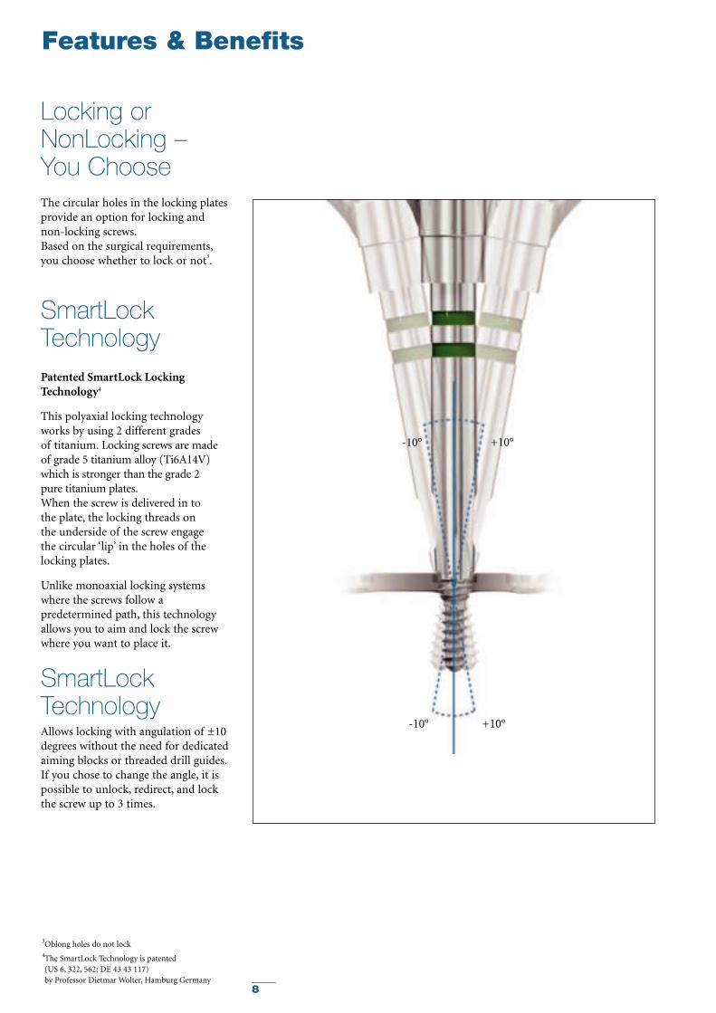
The circular holes in the locking platesprovide an option for locking and non-locking screws.Based on the surgical requirements,you choose whether to lock or not3.
Patented SmartLock LockingTechnology4
This polyaxial locking technologyworks by using 2 different grades of titanium. Locking screws are made of grade 5 titanium alloy (Ti6A14V)which is stronger than the grade 2 pure titanium plates.When the screw is delivered in to the plate, the locking threads on the underside of the screw engage the circular ‘lip’ in the holes of thelocking plates.
Unlike monoaxial locking systemswhere the screws follow apredetermined path, this technologyallows you to aim and lock the screwwhere you want to place it.
Allows locking with angulation of ±10degrees without the need for dedicatedaiming blocks or threaded drill guides.If you chose to change the angle, it ispossible to unlock, redirect, and lockthe screw up to 3 times.
-10° +10°
+10°-10°
9
VariA
xH
and
Lockin
g P
late
Module
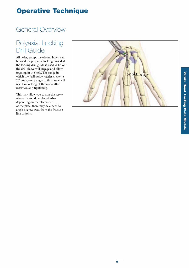
Polyaxial LockingDrill GuideAll holes, except the oblong holes, canbe used for polyaxial locking providedthe locking drill guide is used. A lip onthe drill sleeve will engage and allowtoggling in the hole. The range inwhich the drill guide toggles creates a20o cone; every angle in this range willresult in locking of the screw afterinsertion and tightening.
This may allow you to aim the screwwhere it should be placed. Also,depending on the placement of the plate, there may be a need toangle a screw away from the fractureline or joint.
20° ‘locking cone’
Operative Technique
General Overview
10
Operative Technique
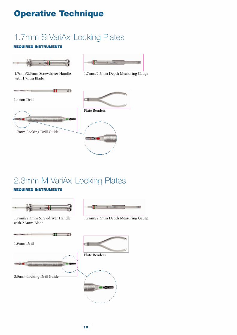
1.7mm S VariAx Locking PlatesREQUIRED INSTRUMENTS
2.3mm M VariAx Locking PlatesREQUIRED INSTRUMENTS
1.7mm Locking Drill Guide
1.7mm/2.3mm Screwdriver Handlewith 1.7mm Blade
1.7mm/2.3mm Depth Measuring Gauge
Plate Benders
1.4mm Drill
2.3mm Locking Drill Guide
1.7mm/2.3mm Depth Measuring Gauge
Plate Benders
1.7mm/2.3mm Screwdriver Handlewith 2.3mm Blade
1.9mm Drill
11
VariA
xH
and
Lockin
g P
late
Module
Operative Technique
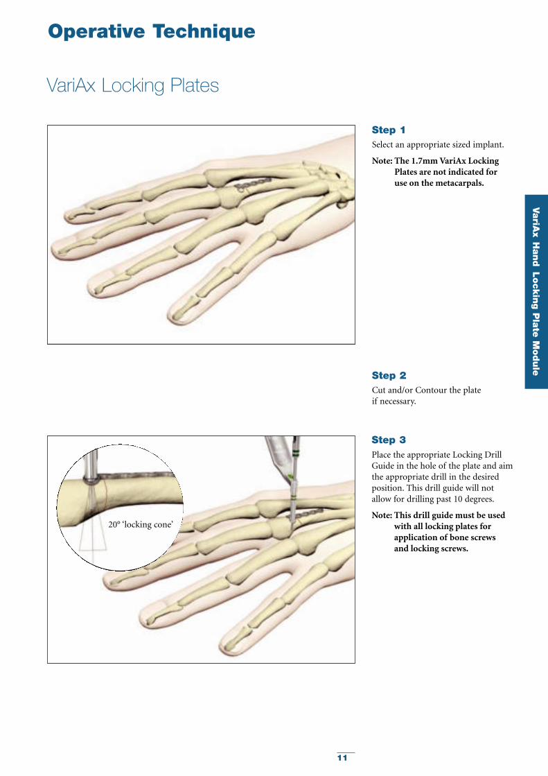
VariAx Locking Plates
Select an appropriate sized implant.
Note: The 1.7mm VariAx LockingPlates are not indicated for use on the metacarpals.
Step 1
Cut and/or Contour the plate if necessary.
Step 2
Place the appropriate Locking DrillGuide in the hole of the plate and aimthe appropriate drill in the desiredposition. This drill guide will notallow for drilling past 10 degrees.
Note: This drill guide must be usedwith all locking plates forapplication of bone screws and locking screws.
Step 3
20° ‘locking cone’
12
Operative Technique
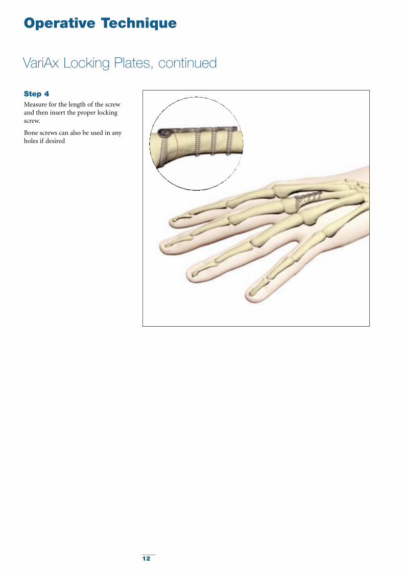
VariAx Locking Plates, continued
Measure for the length of the screwand then insert the proper lockingscrew.
Bone screws can also be used in anyholes if desired
Step 4
13
VariA
xH
and
Lockin
g P
late
Module
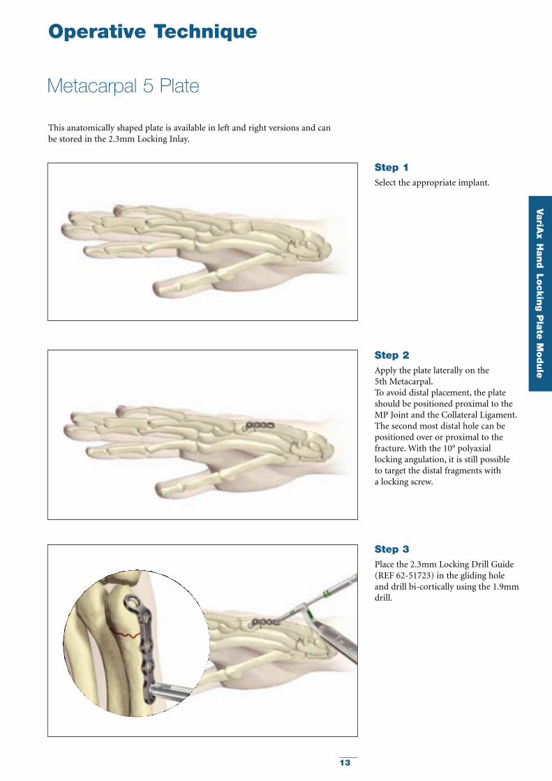
Select the appropriate implant.
Step 1
Apply the plate laterally on the 5th Metacarpal.To avoid distal placement, the plateshould be positioned proximal to theMP Joint and the Collateral Ligament.The second most distal hole can bepositioned over or proximal to thefracture. With the 10° polyaxiallocking angulation, it is still possible to target the distal fragments with a locking screw.
Step 2
Place the 2.3mm Locking Drill Guide(REF 62-51723) in the gliding holeand drill bi-cortically using the 1.9mmdrill.
Step 3
Operative Technique
Metacarpal 5 Plate
This anatomically shaped plate is available in left and right versions and can be stored in the 2.3mm Locking Inlay.
14
Operative Technique
Metacarpal 5 Plate, continued
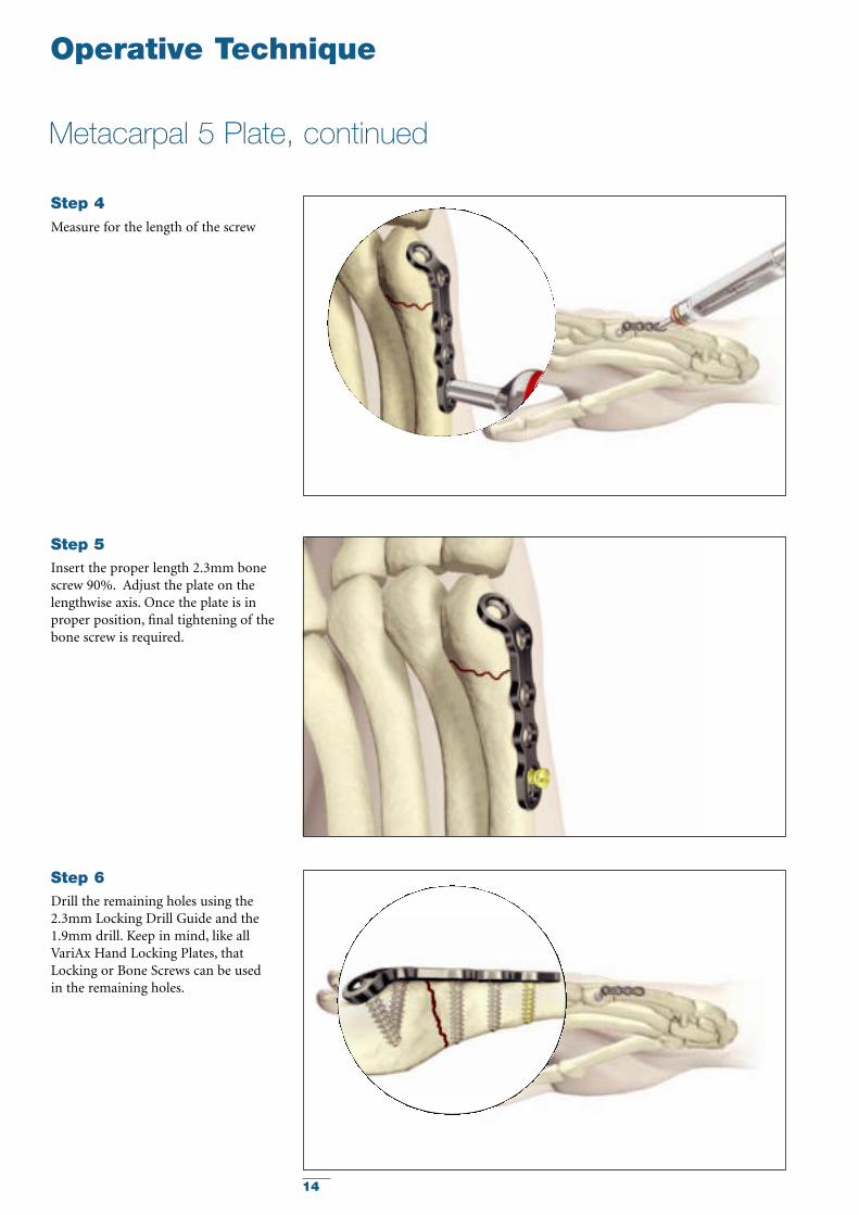
Measure for the length of the screw
Step 4
Insert the proper length 2.3mm bonescrew 90%. Adjust the plate on thelengthwise axis. Once the plate is inproper position, final tightening of thebone screw is required.
Step 5
Drill the remaining holes using the2.3mm Locking Drill Guide and the1.9mm drill. Keep in mind, like allVariAx Hand Locking Plates, thatLocking or Bone Screws can be used in the remaining holes.
Step 6
15
VariA
xH
and
Lockin
g P
late
Module
Operative Technique
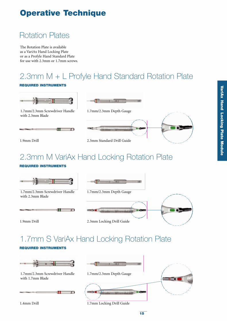
2.3mm M + L Profyle Hand Standard Rotation PlateREQUIRED INSTRUMENTS
1.7mm/2.3mm Screwdriver Handlewith 2.3mm Blade
2.3mm Standard Drill Guide1.9mm Drill
1.7mm/2.3mm Depth Gauge
2.3mm M VariAx Hand Locking Rotation PlateREQUIRED INSTRUMENTS
1.7mm/2.3mm Screwdriver Handlewith 2.3mm Blade
2.3mm Locking Drill Guide1.9mm Drill
1.7mm/2.3mm Depth Gauge
1.7mm S VariAx Hand Locking Rotation PlateREQUIRED INSTRUMENTS
1.7mm/2.3mm Screwdriver Handlewith 1.7mm Blade
1.7mm Locking Drill Guide1.4mm Drill
1.7mm/2.3mm Depth Gauge
Rotation PlatesThe Rotation Plate is available as a VariAx Hand Locking Plate or as a Profyle Hand Standard Platefor use with 2.3mm or 1.7mm screws.
16
Operative Technique
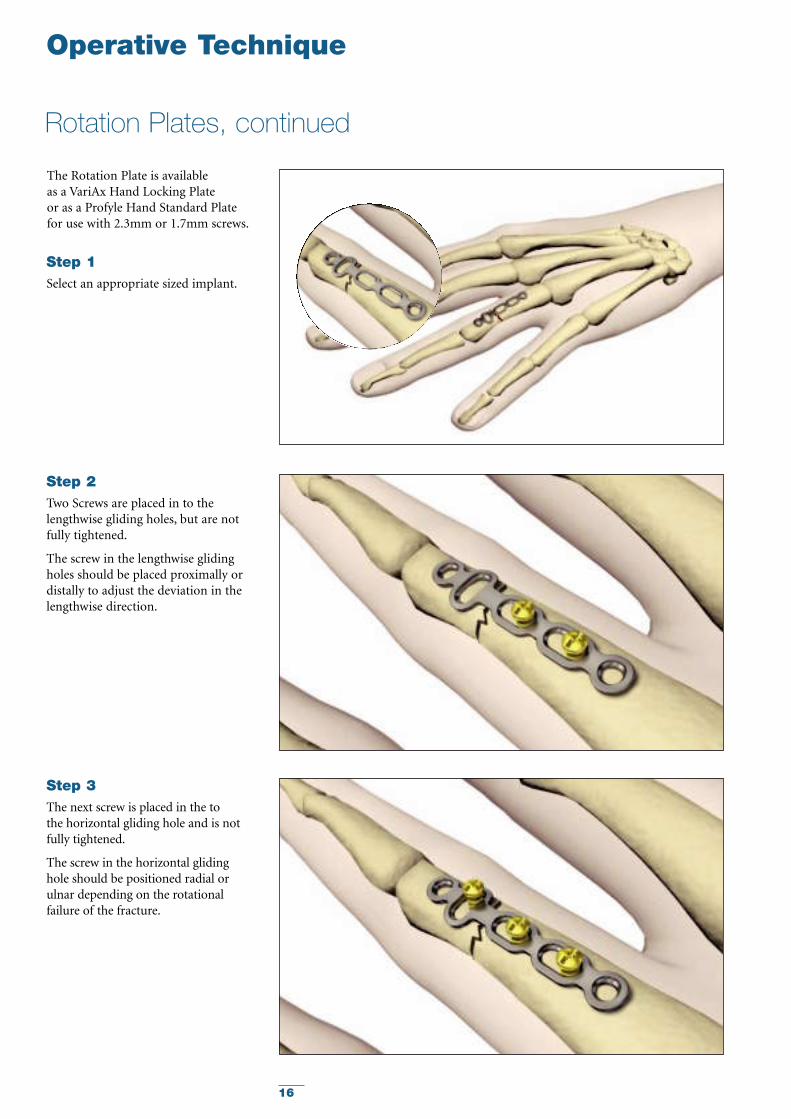
Rotation Plates, continued
Select an appropriate sized implant.
Step 1
Two Screws are placed in to thelengthwise gliding holes, but are notfully tightened.
The screw in the lengthwise glidingholes should be placed proximally ordistally to adjust the deviation in thelengthwise direction.
Step 2
The next screw is placed in the to the horizontal gliding hole and is notfully tightened.
The screw in the horizontal glidinghole should be positioned radial orulnar depending on the rotationalfailure of the fracture.
Step 3
The Rotation Plate is available as a VariAx Hand Locking Plate or as a Profyle Hand Standard Platefor use with 2.3mm or 1.7mm screws.
17
VariA
xH
and
Lockin
g P
late
Module
Operative Technique
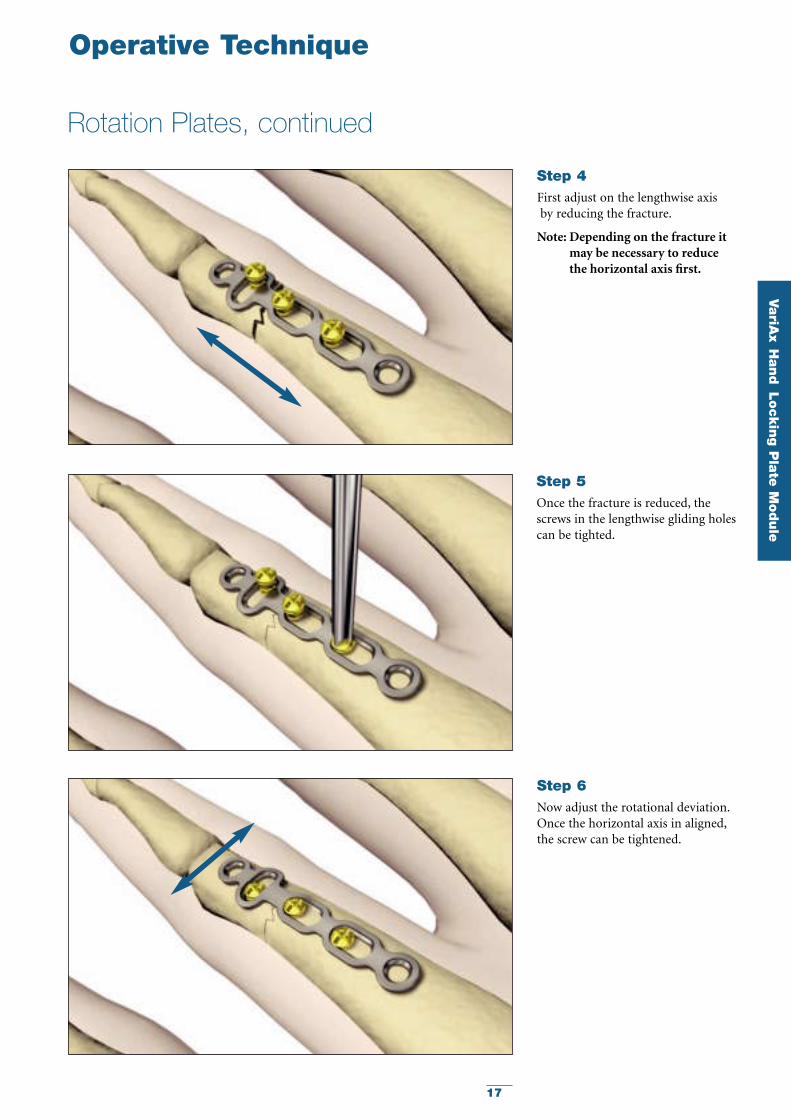
Rotation Plates, continued
Once the fracture is reduced, thescrews in the lengthwise gliding holescan be tighted.
First adjust on the lengthwise axisby reducing the fracture.
Note: Depending on the fracture itmay be necessary to reduce the horizontal axis first.
Step 4
Now adjust the rotational deviation.Once the horizontal axis in aligned,the screw can be tightened.
Step 6
Step 5
18
Operative Technique
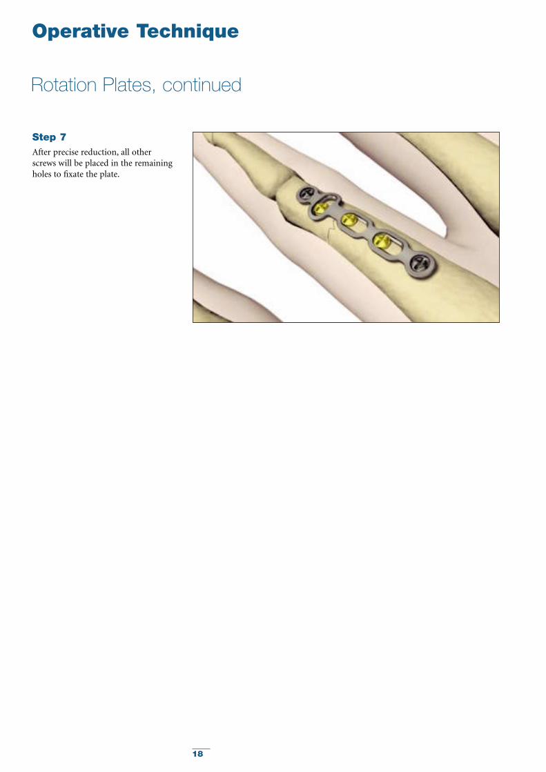
Rotation Plates, continued
After precise reduction, all otherscrews will be placed in the remainingholes to fixate the plate.
Step 7
19
Pro
fyle H
and
Sta
ndard
Pla
te M
odule
Profyle Hand Standard Plating Module
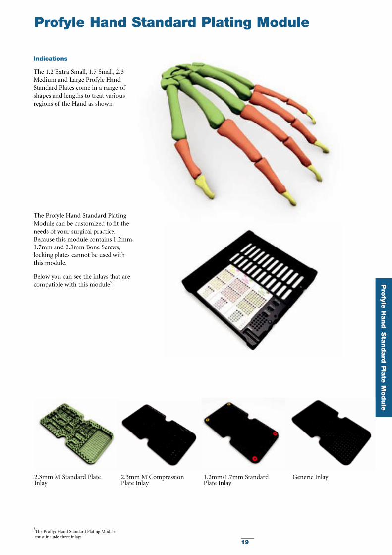
Indications
The 1.2 Extra Small, 1.7 Small, 2.3Medium and Large Profyle HandStandard Plates come in a range ofshapes and lengths to treat variousregions of the Hand as shown:
5The Proflye Hand Standard Plating Module must include three inlays
The Profyle Hand Standard PlatingModule can be customized to fit theneeds of your surgical practice.Because this module contains 1.2mm,1.7mm and 2.3mm Bone Screws,locking plates cannot be used with this module.
Below you can see the inlays that arecompatible with this module5:
2.3mm M Standard PlateInlay
2.3mm M CompressionPlate Inlay
1.2mm/1.7mm StandardPlate Inlay
Generic Inlay
20
Operative Technique
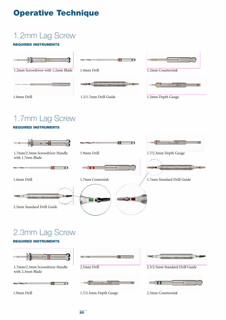
1.2mm Lag ScrewREQUIRED INSTRUMENTS
1.2/1.7mm Drill Guide
1.2mm Screwdriver with 1.2mm Blade 1.2mm Countersink
1.2mm Depth Gauge1.0mm Drill
1.4mm Drill
1.7mm Lag ScrewREQUIRED INSTRUMENTS
1.7mm/2.3mm Screwdriver Handlewith 1.7mm Blade
1.7/2.3mm Depth Gauge
1.7mm Coutersink 1.7mm Standard Drill Guide
2.3mm Standard Drill Guide
1.4mm Drill
1.9mm Drill
2.3mm Lag ScrewREQUIRED INSTRUMENTS
1.7mm/2.3mm Screwdriver Handlewith 2.3mm Blade
2.3/2.5mm Standard Drill Guide
1.7/2.3mm Depth Gauge1.9mm Drill
2.5mm Drill
2.3mm Countersink
21
Pro
fyle H
and
Sta
ndard
Pla
te M
odule
Operative Technique
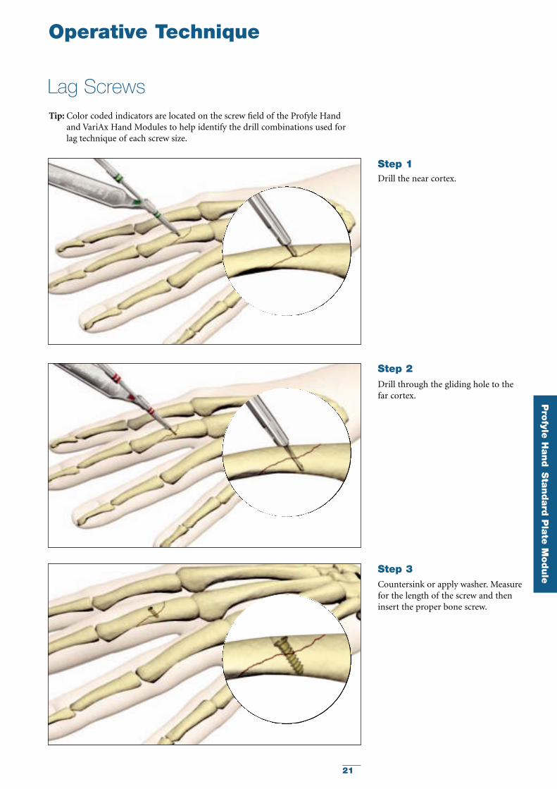
Lag Screws
Drill the near cortex.
Step 1
Drill through the gliding hole to thefar cortex.
Step 2
Countersink or apply washer. Measurefor the length of the screw and theninsert the proper bone screw.
Step 3
Tip: Color coded indicators are located on the screw field of the Profyle Hand and VariAx Hand Modules to help identify the drill combinations used for lag technique of each screw size.
22
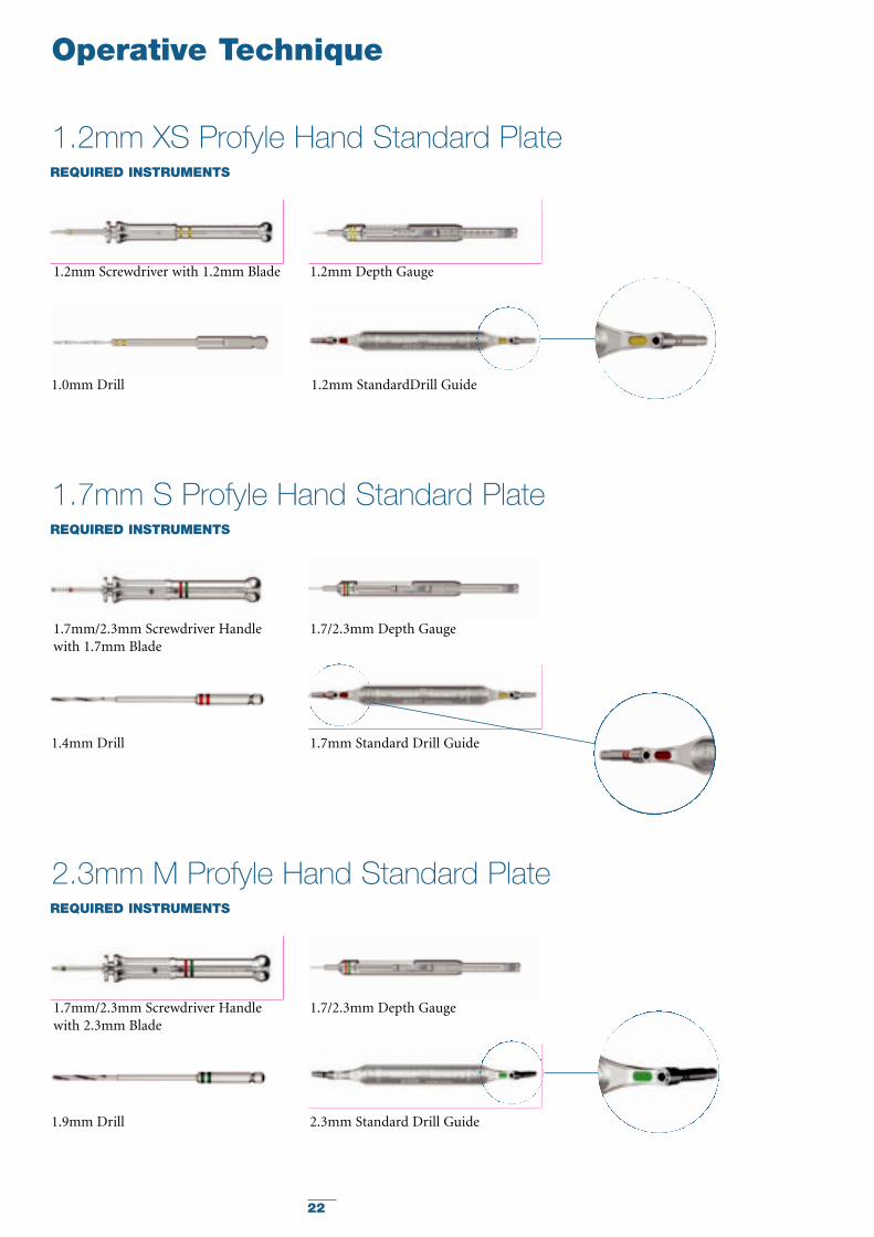
Operative Technique
1.2mm XS Profyle Hand Standard PlateREQUIRED INSTRUMENTS
1.2mm StandardDrill Guide
1.2mm Screwdriver with 1.2mm Blade
1.0mm Drill
1.2mm Depth Gauge
1.7mm S Profyle Hand Standard PlateREQUIRED INSTRUMENTS
1.7mm/2.3mm Screwdriver Handlewith 1.7mm Blade
1.7mm Standard Drill Guide1.4mm Drill
1.7/2.3mm Depth Gauge
2.3mm M Profyle Hand Standard PlateREQUIRED INSTRUMENTS
1.7mm/2.3mm Screwdriver Handlewith 2.3mm Blade
2.3mm Standard Drill Guide1.9mm Drill
1.7/2.3mm Depth Gauge
23
Pro
fyle H
and
Sta
ndard
Pla
te M
odule
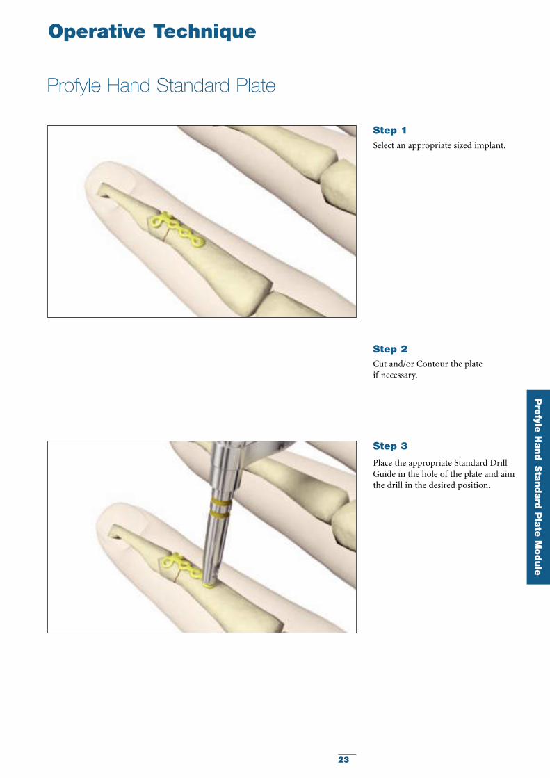
Operative Technique
Profyle Hand Standard Plate
Select an appropriate sized implant.
Step 1
Cut and/or Contour the plate if necessary.
Step 2
Place the appropriate Standard DrillGuide in the hole of the plate and aimthe drill in the desired position.
Step 3
24
Operative Technique
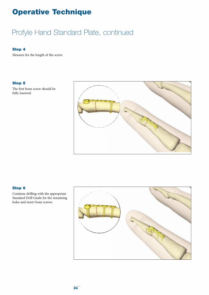
Profyle Hand Standard Plate, continued
Measure for the length of the screw.
Step 4
The first bone screw should be fully inserted.
Step 5
Continue drilling with the appropriateStandard Drill Guide for the remainingholes and insert bone screws.
Step 6
25
Pro
fyle H
and
Sta
ndard
Pla
te M
odule
Profyle Compression Plates
Operative Technique
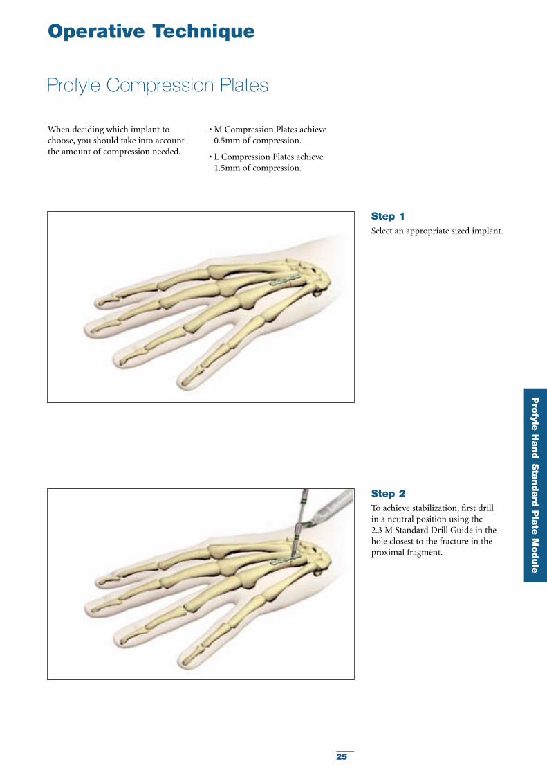
Select an appropriate sized implant.
Step 1
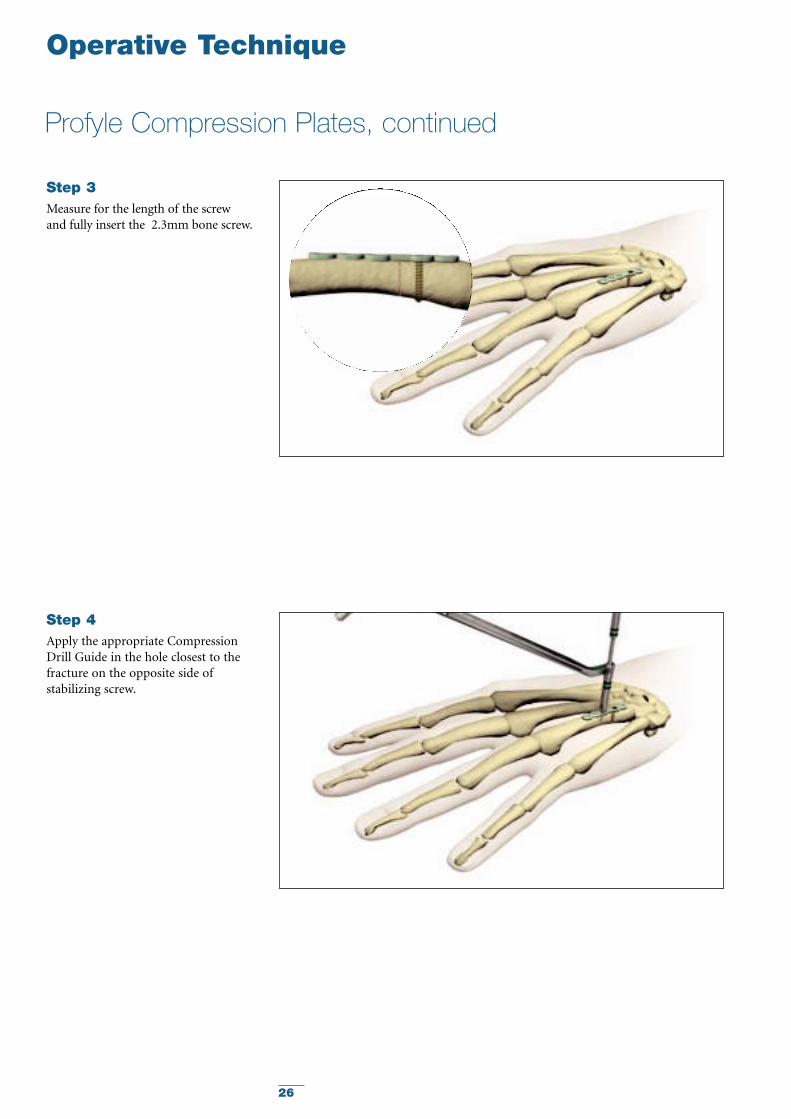
To achieve stabilization, first drill in a neutral position using the 2.3 M Standard Drill Guide in the hole closest to the fracture in theproximal fragment.
Step 2
When deciding which implant tochoose, you should take into accountthe amount of compression needed.
• M Compression Plates achieve0.5mm of compression.
• L Compression Plates achieve1.5mm of compression.
26
Profyle Compression Plates, continued
Operative Technique
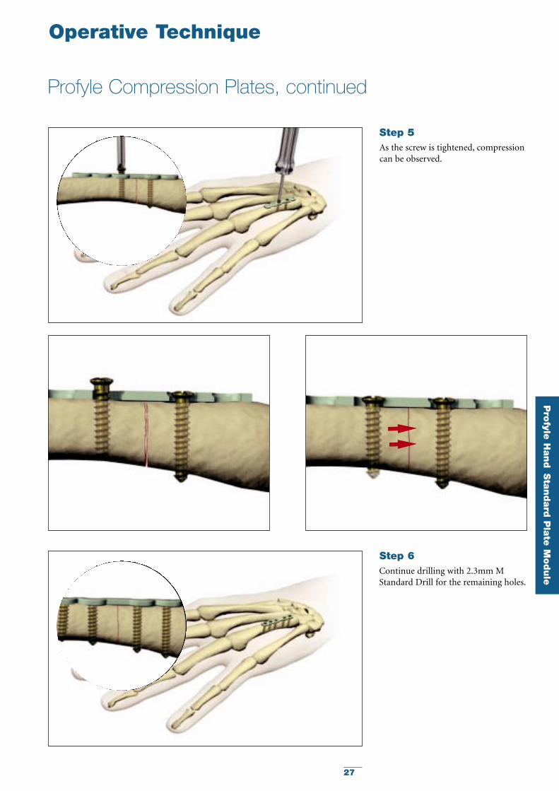
Apply the appropriate CompressionDrill Guide in the hole closest to thefracture on the opposite side ofstabilizing screw.
Step 4
Measure for the length of the screwand fully insert the 2.3mm bone screw.
Step 3
27
Pro
fyle H
and
Sta
ndard
Pla
te M
odule
Profyle Compression Plates, continued
Operative Technique
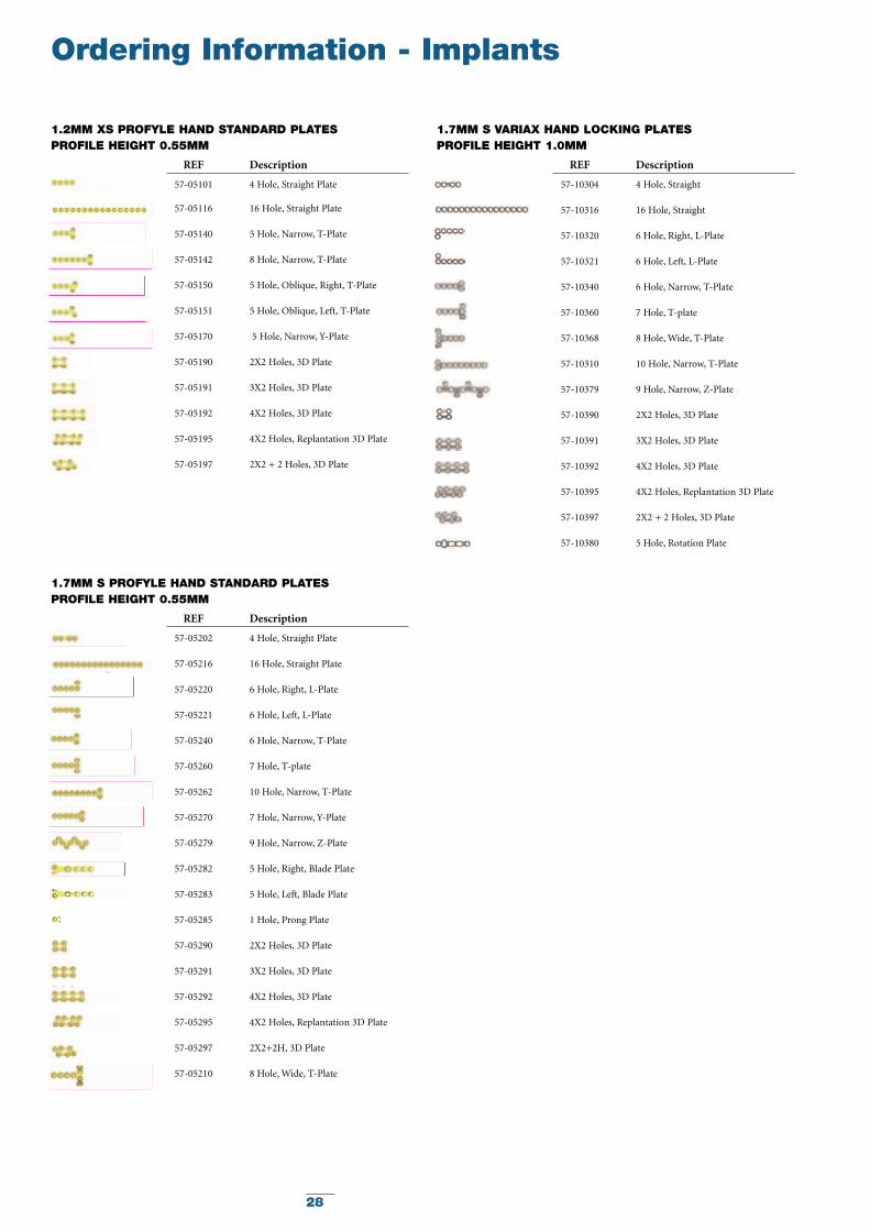
Continue drilling with 2.3mm MStandard Drill for the remaining holes.
Step 6
As the screw is tightened, compressioncan be observed.
Step 5
28
Ordering Information - Implants
REF Description
57-05101 4 Hole, Straight Plate
57-05116 16 Hole, Straight Plate
57-05140 5 Hole, Narrow, T-Plate
57-05142 8 Hole, Narrow, T-Plate
57-05150 5 Hole, Oblique, Right, T-Plate
57-05151 5 Hole, Oblique, Left, T-Plate
57-05170 5 Hole, Narrow, Y-Plate
57-05190 2X2 Holes, 3D Plate
57-05191 3X2 Holes, 3D Plate
57-05192 4X2 Holes, 3D Plate
57-05195 4X2 Holes, Replantation 3D Plate
57-05197 2X2 + 2 Holes, 3D Plate
1.2MM XS PROFYLE HAND STANDARD PLATESPROFILE HEIGHT 0.55MM
REF Description
57-10304 4 Hole, Straight
57-10316 16 Hole, Straight
57-10320 6 Hole, Right, L-Plate
57-10321 6 Hole, Left, L-Plate
57-10340 6 Hole, Narrow, T-Plate
57-10360 7 Hole, T-plate
57-10368 8 Hole, Wide, T-Plate
57-10310 10 Hole, Narrow, T-Plate
57-10379 9 Hole, Narrow, Z-Plate
57-10390 2X2 Holes, 3D Plate
57-10391 3X2 Holes, 3D Plate
57-10392 4X2 Holes, 3D Plate
57-10395 4X2 Holes, Replantation 3D Plate
57-10397 2X2 + 2 Holes, 3D Plate
57-10380 5 Hole, Rotation Plate
1.7MM S VARIAX HAND LOCKING PLATESPROFILE HEIGHT 1.0MM
REF Description
57-05202 4 Hole, Straight Plate
57-05216 16 Hole, Straight Plate
57-05220 6 Hole, Right, L-Plate
57-05221 6 Hole, Left, L-Plate
57-05240 6 Hole, Narrow, T-Plate
57-05260 7 Hole, T-plate
57-05262 10 Hole, Narrow, T-Plate
57-05270 7 Hole, Narrow, Y-Plate
57-05279 9 Hole, Narrow, Z-Plate
57-05282 5 Hole, Right, Blade Plate
57-05283 5 Hole, Left, Blade Plate
57-05285 1 Hole, Prong Plate
57-05290 2X2 Holes, 3D Plate
57-05291 3X2 Holes, 3D Plate
57-05292 4X2 Holes, 3D Plate
57-05295 4X2 Holes, Replantation 3D Plate
57-05297 2X2+2H, 3D Plate
57-05210 8 Hole, Wide, T-Plate
1.7MM S PROFYLE HAND STANDARD PLATESPROFILE HEIGHT 0.55MM
29
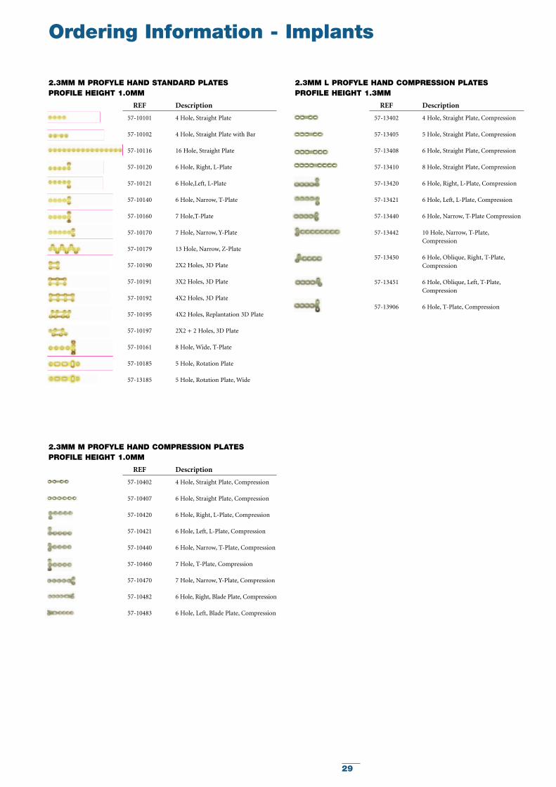
Ordering Information - Implants
REF Description
57-10101 4 Hole, Straight Plate
57-10102 4 Hole, Straight Plate with Bar
57-10116 16 Hole, Straight Plate
57-10120 6 Hole, Right, L-Plate
57-10121 6 Hole,Left, L-Plate
57-10140 6 Hole, Narrow, T-Plate
57-10160 7 Hole,T-Plate
57-10170 7 Hole, Narrow, Y-Plate
57-10179 13 Hole, Narrow, Z-Plate
57-10190 2X2 Holes, 3D Plate
57-10191 3X2 Holes, 3D Plate
57-10192 4X2 Holes, 3D Plate
57-10195 4X2 Holes, Replantation 3D Plate
57-10197 2X2 + 2 Holes, 3D Plate
57-10161 8 Hole, Wide, T-Plate
57-10185 5 Hole, Rotation Plate
57-13185 5 Hole, Rotation Plate, Wide
2.3MM M PROFYLE HAND STANDARD PLATESPROFILE HEIGHT 1.0MM
REF Description
57-13402 4 Hole, Straight Plate, Compression
57-13405 5 Hole, Straight Plate, Compression
57-13408 6 Hole, Straight Plate, Compression
57-13410 8 Hole, Straight Plate, Compression
57-13420 6 Hole, Right, L-Plate, Compression
57-13421 6 Hole, Left, L-Plate, Compression
57-13440 6 Hole, Narrow, T-Plate Compression
57-13442 10 Hole, Narrow, T-Plate,Compression
57-13450 6 Hole, Oblique, Right, T-Plate,Compression
57-13451 6 Hole, Oblique, Left, T-Plate,Compression
57-13906 6 Hole, T-Plate, Compression
2.3MM L PROFYLE HAND COMPRESSION PLATESPROFILE HEIGHT 1.3MM
REF Description
57-10402 4 Hole, Straight Plate, Compression
57-10407 6 Hole, Straight Plate, Compression
57-10420 6 Hole, Right, L-Plate, Compression
57-10421 6 Hole, Left, L-Plate, Compression
57-10440 6 Hole, Narrow, T-Plate, Compression
57-10460 7 Hole, T-Plate, Compression
57-10470 7 Hole, Narrow, Y-Plate, Compression
57-10482 6 Hole, Right, Blade Plate, Compression
57-10483 6 Hole, Left, Blade Plate, Compression
2.3MM M PROFYLE HAND COMPRESSION PLATESPROFILE HEIGHT 1.0MM
30
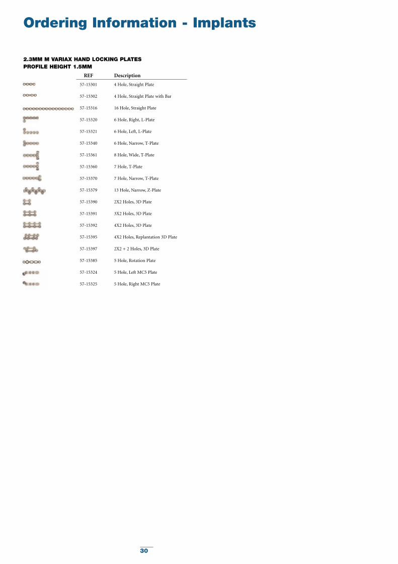
Ordering Information - Implants
REF Description
57-15301 4 Hole, Straight Plate
57-15302 4 Hole, Straight Plate with Bar
57-15316 16 Hole, Straight Plate
57-15320 6 Hole, Right, L-Plate
57-15321 6 Hole, Left, L-Plate
57-15340 6 Hole, Narrow, T-Plate
57-15361 8 Hole, Wide, T-Plate
57-15360 7 Hole, T-Plate
57-15370 7 Hole, Narrow, T-Plate
57-15379 13 Hole, Narrow, Z-Plate
57-15390 2X2 Holes, 3D Plate
57-15391 3X2 Holes, 3D Plate
57-15392 4X2 Holes, 3D Plate
57-15395 4X2 Holes, Replantation 3D Plate
57-15397 2X2 + 2 Holes, 3D Plate
57-15385 5 Hole, Rotation Plate
57-15324 5 Hole, Left MC5 Plate
57-15325 5 Hole, Right MC5 Plate
2.3MM M VARIAX HAND LOCKING PLATESPROFILE HEIGHT 1.5MM
31
Ordering Information - Implants
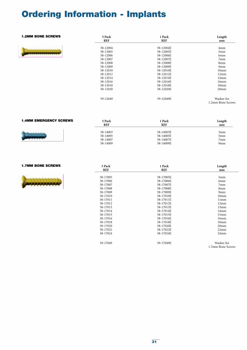
5 Pack 1 Pack LengthREF REF mm
58-12004 58-12004E 4mm58-12005 58-12005E 5mm58-12006 58-12006E 6mm58-12007 58-12007E 7mm58-12008 58-12008E 8mm58-12009 58-12009E 9mm58-12010 58-12010E 10mm58-12012 58-12012E 12mm58-12014 58-12014E 14mm58-12016 58-12016E 16mm58-12018 58-12018E 18mm58-12020 58-12020E 20mm
59-12049 59-12049E Washer for 1.2mm Bone Screws
1.2MM BONE SCREWS
5 Pack 1 Pack LengthREF REF mm
58-14003 58-14003E 3mm58-14005 58-14005E 5mm58-14007 58-14007E 7mm58-14009 58-14009E 9mm
1.4MM EMERGENCY SCREWS
5 Pack 1 Pack LengthREF REF mm
58-17005 58-17005E 5mm58-17006 58-17006E 6mm58-17007 58-17007E 7mm58-17008 58-17008E 8mm58-17009 58-17009E 9mm58-17010 58-17010E 10mm58-17011 58-17011E 11mm58-17012 58-17012E 12mm58-17013 58-17013E 13mm58-17014 58-17014E 14mm58-17015 58-17015E 15mm58-17016 58-17016E 16mm58-17018 58-17018E 18mm58-17020 58-17020E 20mm58-17022 58-17022E 22mm58-17024 58-17024E 24mm
59-17049 59-17049E Washer for 1.7mm Bone Screws
1.7MM BONE SCREWS
32
Ordering Information - Implants
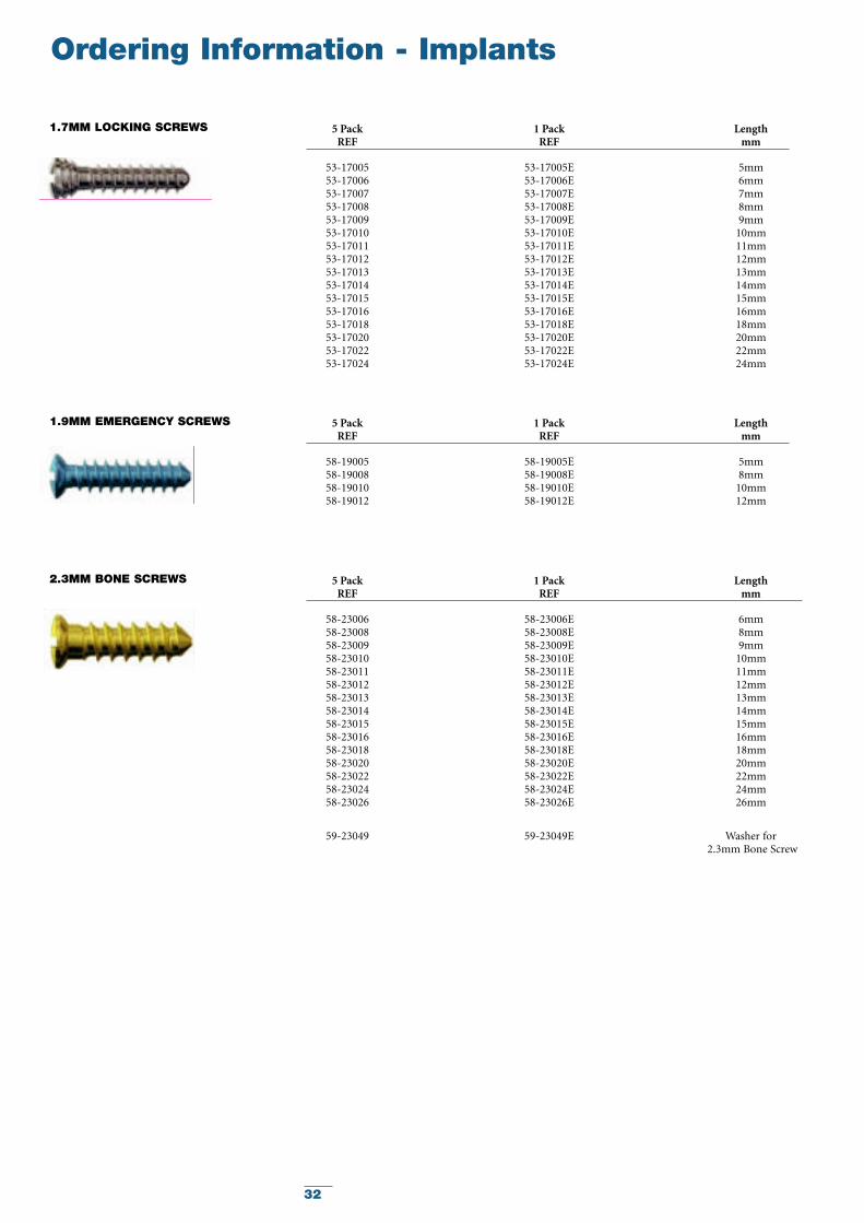
5 Pack 1 Pack LengthREF REF mm
53-17005 53-17005E 5mm53-17006 53-17006E 6mm53-17007 53-17007E 7mm53-17008 53-17008E 8mm53-17009 53-17009E 9mm53-17010 53-17010E 10mm53-17011 53-17011E 11mm53-17012 53-17012E 12mm53-17013 53-17013E 13mm53-17014 53-17014E 14mm53-17015 53-17015E 15mm53-17016 53-17016E 16mm53-17018 53-17018E 18mm53-17020 53-17020E 20mm53-17022 53-17022E 22mm53-17024 53-17024E 24mm
1.7MM LOCKING SCREWS
5 Pack 1 Pack LengthREF REF mm
58-19005 58-19005E 5mm58-19008 58-19008E 8mm58-19010 58-19010E 10mm58-19012 58-19012E 12mm
1.9MM EMERGENCY SCREWS
5 Pack 1 Pack LengthREF REF mm
58-23006 58-23006E 6mm58-23008 58-23008E 8mm58-23009 58-23009E 9mm58-23010 58-23010E 10mm58-23011 58-23011E 11mm58-23012 58-23012E 12mm58-23013 58-23013E 13mm58-23014 58-23014E 14mm58-23015 58-23015E 15mm58-23016 58-23016E 16mm58-23018 58-23018E 18mm58-23020 58-23020E 20mm58-23022 58-23022E 22mm58-23024 58-23024E 24mm58-23026 58-23026E 26mm
59-23049 59-23049E Washer for2.3mm Bone Screw
2.3MM BONE SCREWS
33
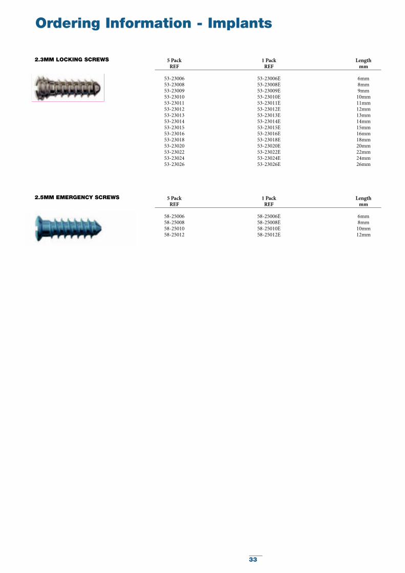
Ordering Information - Implants
5 Pack 1 Pack LengthREF REF mm
53-23006 53-23006E 6mm53-23008 53-23008E 8mm53-23009 53-23009E 9mm53-23010 53-23010E 10mm53-23011 53-23011E 11mm53-23012 53-23012E 12mm53-23013 53-23013E 13mm53-23014 53-23014E 14mm53-23015 53-23015E 15mm53-23016 53-23016E 16mm53-23018 53-23018E 18mm53-23020 53-23020E 20mm53-23022 53-23022E 22mm53-23024 53-23024E 24mm53-23026 53-23026E 26mm
2.3MM LOCKING SCREWS
5 Pack 1 Pack LengthREF REF mm
58-25006 58-25006E 6mm58-25008 58-25008E 8mm58-25010 58-25010E 10mm58-25012 58-25012E 12mm
2.5MM EMERGENCY SCREWS
34
Ordering Information - Instruments
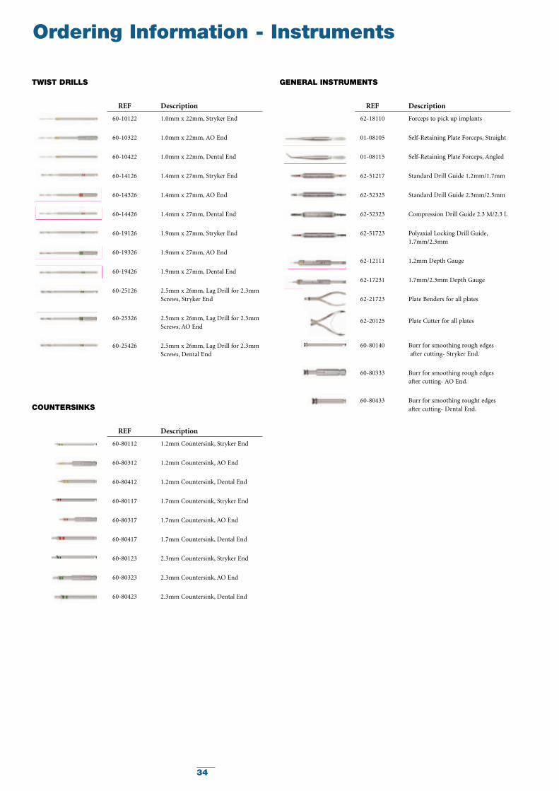
TWIST DRILLS
REF Description
60-10122 1.0mm x 22mm, Stryker End
60-10322 1.0mm x 22mm, AO End
60-10422 1.0mm x 22mm, Dental End
60-14126 1.4mm x 27mm, Stryker End
60-14326 1.4mm x 27mm, AO End
60-14426 1.4mm x 27mm, Dental End
60-19126 1.9mm x 27mm, Stryker End
60-19326 1.9mm x 27mm, AO End
60-19426 1.9mm x 27mm, Dental End
60-25126 2.5mm x 26mm, Lag Drill for 2.3mmScrews, Stryker End
60-25326 2.5mm x 26mm, Lag Drill for 2.3mmScrews, AO End
60-25426 2.5mm x 26mm, Lag Drill for 2.3mmScrews, Dental End
GENERAL INSTRUMENTS
REF Description
62-18110 Forceps to pick up implants
01-08105 Self-Retaining Plate Forceps, Straight
01-08115 Self-Retaining Plate Forceps, Angled
62-51217 Standard Drill Guide 1.2mm/1.7mm
62-52325 Standard Drill Guide 2.3mm/2.5mm
62-52323 Compression Drill Guide 2.3 M/2.3 L
62-51723 Polyaxial Locking Drill Guide,1.7mm/2.3mm
62-12111 1.2mm Depth Gauge
62-17231 1.7mm/2.3mm Depth Gauge
62-21723 Plate Benders for all plates
62-20125 Plate Cutter for all plates
60-80140 Burr for smoothing rough edgesafter cutting- Stryker End.
60-80333 Burr for smoothing rough edges after cutting- AO End.
60-80433 Burr for smoothing rought edges after cutting- Dental End.COUNTERSINKS
REF Description
60-80112 1.2mm Countersink, Stryker End
60-80312 1.2mm Countersink, AO End
60-80412 1.2mm Countersink, Dental End
60-80117 1.7mm Countersink, Stryker End
60-80317 1.7mm Countersink, AO End
60-80417 1.7mm Countersink, Dental End
60-80123 2.3mm Countersink, Stryker End
60-80323 2.3mm Countersink, AO End
60-80423 2.3mm Countersink, Dental End
35
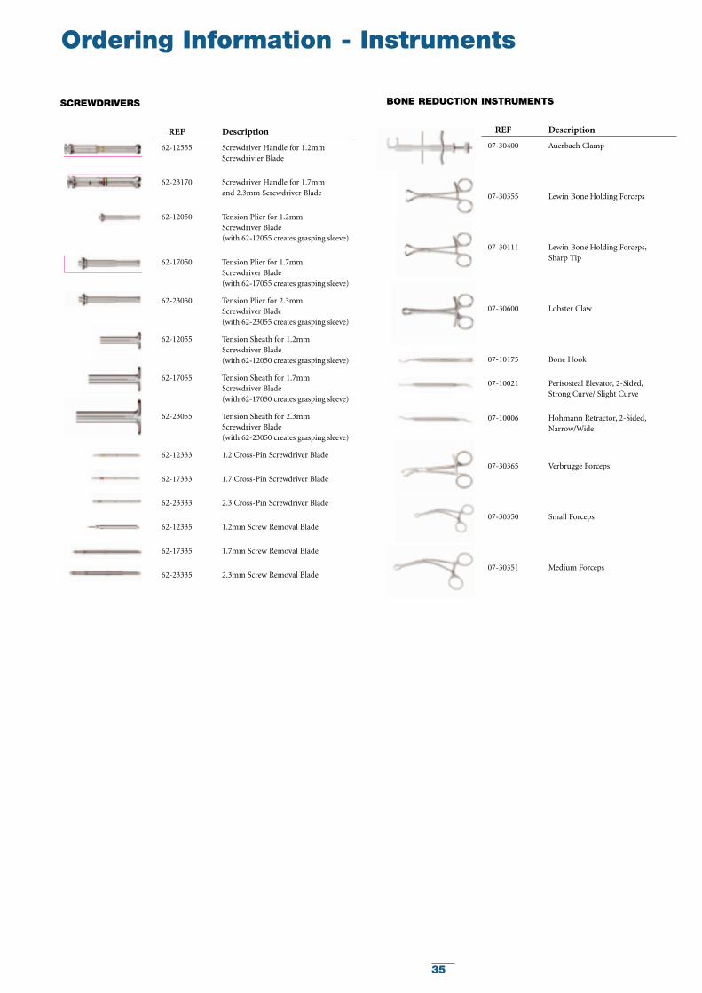
BONE REDUCTION INSTRUMENTS
REF Description
07-30400 Auerbach Clamp
07-30355 Lewin Bone Holding Forceps
07-30111 Lewin Bone Holding Forceps,Sharp Tip
07-30600 Lobster Claw
07-10175 Bone Hook
07-10021 Perisosteal Elevator, 2-Sided,Strong Curve/ Slight Curve
07-10006 Hohmann Retractor, 2-Sided,Narrow/Wide
07-30365 Verbrugge Forceps
07-30350 Small Forceps
07-30351 Medium Forceps
SCREWDRIVERS
REF Description
62-12555 Screwdriver Handle for 1.2mm Screwdrivier Blade
62-23170 Screwdriver Handle for 1.7mm and 2.3mm Screwdriver Blade
62-12050 Tension Plier for 1.2mm Screwdriver Blade (with 62-12055 creates grasping sleeve)
62-17050 Tension Plier for 1.7mm Screwdriver Blade (with 62-17055 creates grasping sleeve)
62-23050 Tension Plier for 2.3mm Screwdriver Blade (with 62-23055 creates grasping sleeve)
62-12055 Tension Sheath for 1.2mm Screwdriver Blade (with 62-12050 creates grasping sleeve)
62-17055 Tension Sheath for 1.7mm Screwdriver Blade (with 62-17050 creates grasping sleeve)
62-23055 Tension Sheath for 2.3mmScrewdriver Blade (with 62-23050 creates grasping sleeve)
62-12333 1.2 Cross-Pin Screwdriver Blade
62-17333 1.7 Cross-Pin Screwdriver Blade
62-23333 2.3 Cross-Pin Screwdriver Blade
62-12335 1.2mm Screw Removal Blade
62-17335 1.7mm Screw Removal Blade
62-23335 2.3mm Screw Removal Blade
Ordering Information - Instruments
36
Ordering Information - Instruments
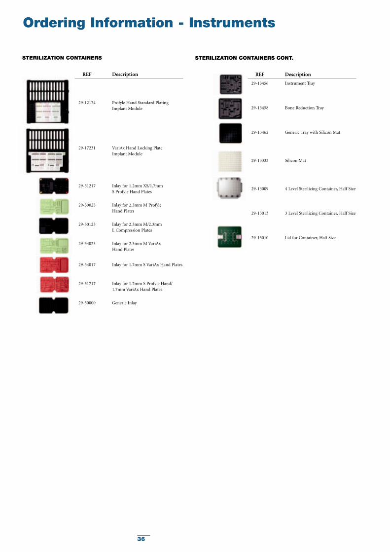
STERILIZATION CONTAINERS
REF Description
29-12174 Profyle Hand Standard PlatingImplant Module
29-17231 VariAx Hand Locking Plate Implant Module
29-51217 Inlay for 1.2mm XS/1.7mm S Profyle Hand Plates
29-50023 Inlay for 2.3mm M Profyle Hand Plates
29-50123 Inlay for 2.3mm M/2.3mm L Compression Plates
29-54023 Inlay for 2.3mm M VariAx Hand Plates
29-54017 Inlay for 1.7mm S VariAx Hand Plates
29-51717 Inlay for 1.7mm S Profyle Hand/1.7mm VariAx Hand Plates
29-50000 Generic Inlay
STERILIZATION CONTAINERS CONT.
REF Description
29-13456 Instrument Tray
29-13458 Bone Reduction Tray
29-13462 Generic Tray with Silicon Mat
29-13333 Silicon Mat
29-13009 4 Level Sterilizing Container, Half Size
29-13013 3 Level Sterilizing Container, Half Size
29-13010 Lid for Container, Half Size

37
Notes

38
Notes

39
Notes

Stryker OsteosynthesisBötzinger Straße 4179111 FreiburgGermany
www.osteosynthesis.stryker.com
The information presented in this brochure is intended to demonstrate a Stryker product. Always refer to the package insert, product label and/or user instructions before using any Stryker product. Surgeons must always relyon their own clinical judgment when deciding which products and techniques to use with their patients. Products maynot be available in all markets. Product availability is subject to the regulatory or medical practices that govern individualmarkets. Please contact your Stryker representative if you have questions about the availability of Stryker products inyour area.
Stryker Corporation or its subsidiary owns the registered trademark: StrykerStryker or its subsidiary owns, uses or has applied for the trademark: Variax
Literature Number: 90-07555LOT B2507
Copyright © 2007 StrykerPrinted in Germany
1275