structures studies on geosynthetic-reinforced road pavement · studies on geosynthetic-reinforced...
TRANSCRIPT
Full Terms & Conditions of access and use can be found athttp://www.tandfonline.com/action/journalInformation?journalCode=yjge20
Download by: [84.94.200.65] Date: 17 August 2016, At: 07:35
International Journal of Geotechnical Engineering
ISSN: 1938-6362 (Print) 1939-7879 (Online) Journal homepage: http://www.tandfonline.com/loi/yjge20
Studies on geosynthetic-reinforced road pavementstructures
K. Rajagopal, S. Chandramouli, Anusha Parayil & K. Iniyan
To cite this article: K. Rajagopal, S. Chandramouli, Anusha Parayil & K. Iniyan (2014) Studieson geosynthetic-reinforced road pavement structures, International Journal of GeotechnicalEngineering, 8:3, 287-298, DOI: 10.1179/1939787914Y.0000000042
To link to this article: http://dx.doi.org/10.1179/1939787914Y.0000000042
Published online: 17 Feb 2014.
Submit your article to this journal
Article views: 1134
View related articles
View Crossmark data
Citing articles: 1 View citing articles
Studies on geosynthetic-reinforced roadpavement structures
K. Rajagopal*, S. Chandramouli, Anusha Parayil and K. Iniyan
Many of the pavement structures fail well before their design life owing to the poor quality of
construction materials, inadequate compaction, inadequate preparation of the subgrade, over-
loading, etc. Two options are available to improve the longevity of the pavement. The first option is by
increasing the thickness of different pavement layers and the other option is by increasing the rigidity
of the layers within the system so as to reduce the stresses transferred to the lower layers. Of these
two methods it has been widely observed that increasing the strength and rigidity of the pavement
layers is a more efficient method to lower the stresses on the pavement layers thereby increasing the
life of the pavement.
In the present research work, the improvement in the strength and stiffness of the subbase layer in a
flexible pavement system through the use of geosynthetic layers was investigated by conducting
field plate load tests and a series of laboratory plate load tests. The improvement in the strength of
the pavement is reflected by the increase in modulus of the section reinforced with geosynthetic
layers. This paper will describe the field and laboratory tests, interpretation of the data from these
tests, and the application of this data for design of flexible pavements and their economic analyses.
Keywords: Geosynthetics, Flexible pavements, Geogrids, Geocells, Geotextiles
This paper is part of a special issue on geosynthetics
IntroductionThe performance of highway pavements is governed bythe strength and stiffness of the pavement layers. The costand duration of construction are dependent on theavailability of aggregate materials for construction.Scarcity of natural resources often delays the projects orescalates the costs due to large lead distances from theborrow areas. Hence, it is essential to look at alternativesto achieve improved quality of pavements using newmaterials and reduced usage of natural materials, Giroudand Han (2004). This paper reports on the studies of theperformance of geosynthetic-reinforced flexible pave-ments. Different types of geosynthetics like planar(geogrids and geotextiles) and three dimensional (geocells)can be employed for strengthening the pavement bases.The geocells are three-dimensional honeycomb geosyn-thetic products that provide all round confinement to thesoils. The geocell-confined soil acts like a semi-rigid mat indistributing the surface loads over a wide area of thefoundation soil.
The performance of the geocells as surface confinementlayers and as reinforcement layers has been reported byseveral researchers in the past. Bathurst and Rajagopal(1993) and Rajagopal et al. (1999) have reported thestrength and stiffness behavior of soils confined in singlegeocell and multiple geocell pockets. Madhavi Latha et al.(2008, 2009) have reported the benefit of using geocells asbasal reinforcement layers for embankments constructedon soft foundation soils. It was reported that the factor ofsafety of the slopes can be increased significantly becauseof the interception of the slip surface by the geocell layer.Unni (2010) and Chandramouli (2011) have reported theconstruction of geocell-reinforced unpaved road pave-ments and their performance on different types ofsubgrade layers. Iniyan (2012) has reported the use ofgeogrids for construction of pavements and the improve-ment of the strength of the pavement sections. Based onthe higher modulus obtained with geosynthetic reinforce-ment layers, he has discussed that the pavement thicknesscan be reduced while maintaining the same level of designparameters.
Geocells and geosynthetics are adopted in several roadand ground stabilization projects across the globe. Hanet al. (2008, 2010, 2011) have described the influence of theinfill material and the stiffness on the performance ofgeocells in pavements. Unni (2010), Chandramouli (2011),
Department of Civil Engineering, IIT Madras, Chennai 600 036, India
*Corresponding author, email [email protected]
� 2014 W. S. Maney & Son LtdReceived 13 December 2013; accepted 10 January 2014DOI 10.1179/1939787914Y.0000000042
International Journal ofGeotechnical Engineering 2014 VOL 8 NO 3 287
Iniyan (2012), and Parayil (2013) have reported theperformance of geosynthetic-reinforced flexible pavementsections. They reported that the stresses below thereinforced layers are two to three times lesser than thesurface stresses. Emersleben and Meyer (2010) conductedtest box analysis for 200 mm height geocell filled with sandabove very soft clay and observed that the stresses can bereduced by 30 and 36% depending on the applied load.The load carrying capacity could be improved up to 1?5times due to the reinforcement of dry sand with geocells.Shin et al. (2010) conducted field plate load tests onreinforced and unreinforced subgrade soil and analyzed byusing finite element software. They gave the subgradeimprovement factor of 2. Bush et al. (1990) carried outresearch on geocell-reinforced embankment and con-cluded that the 1 m high geocell with local soil infill willhave 33% lesser settlements after 4 years when comparedto systems with horizontal layers of reinforcement.Further, the cost savings of more than 31% were reportedfor geocell-treated constructions.
The current paper investigates the performance of thereinforced flexible pavements under monotonic andrepeated loads. The granular subbase and sand materialswere obtained from a highway construction site nearChennai. All the index tests were performed to character-ize these materials. Field and laboratory plate load testswere conducted on the flexible pavements. The pressure–settlement data was used to back-calculate the elasticmodulus of the geosynthetic-reinforced pavement layers.
Field studies on geosynthetic flexiblepavements
Geocell-reinforced pavementsThe internal access roads at Govind Dairy Factory inPhaltan, Maharashtra required frequent repairs. Thefoundation soil is typically black cotton soil, whichundergoes severe swelling and shrinking. The propertiesof this soil are given in Table 1. The roads are typicalunpaved roads with thick layers of water-bound Macadam(WBM) and granular subbase (GSB) materials. Nearly200 m long stretch of this road was treated with 150 mmthick geocell layer on an experimental basis to study theperformance improvement.
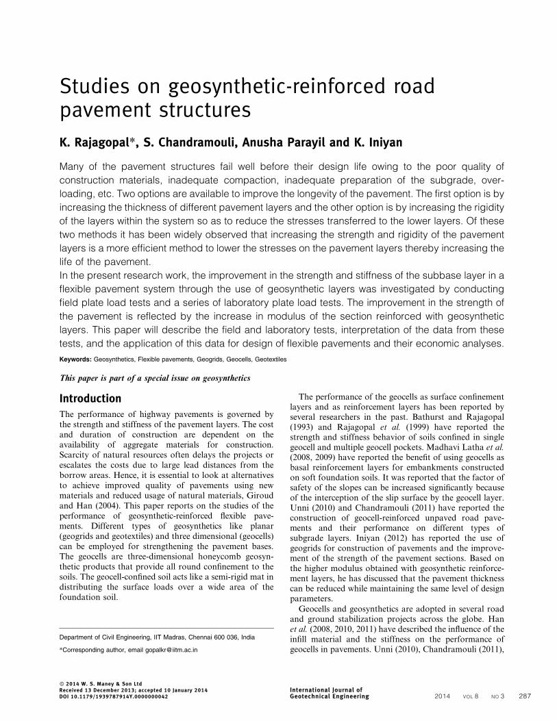
Based on the soil properties and the traffic data, thefollowing designed section of pavement as shown in Fig. 1was used for reconstructing the road using geocellreinforcement. The geocell pockets were filled with GSBmaterials. Water-bound Macadam layers were not usedwithin this stretch of road where geocell was used as areinforcement layer. The bottom most layer was treatedwith 4% lime (hydrated lime) in order to stabilize theexpansive foundation soil. Addition of 3% lime itself wasfound to reduce the plasticity index substantially. Hence,slightly higher percentage of 4% lime addition wasrecommended in order to account for any losses duringinstallation and service life.
The geocell is 150 mm high and made of a polymericalloy. The thickness of the geocell walls is approximately1?2 mm. The c/c weld distance is 330 mm and the pocket
opening dimensions are approximately 2106250 mm. Thetensile strength of the geocell material in strip tension testwas found to be 0?25 kN (ASTM D638-2003) and the peelstrength of the weld is 0?2 kN from ASTM D6392-99standard tensile strength tests. There was no change ofdimensions when pieces of the geocell were exposed to100uC temperature in an oven for 1 h duration (ASTMD1204).
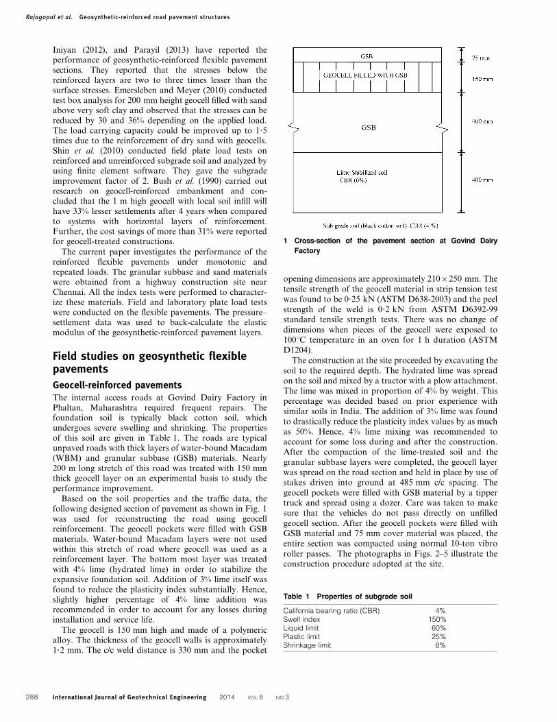
The construction at the site proceeded by excavating thesoil to the required depth. The hydrated lime was spreadon the soil and mixed by a tractor with a plow attachment.The lime was mixed in proportion of 4% by weight. Thispercentage was decided based on prior experience withsimilar soils in India. The addition of 3% lime was foundto drastically reduce the plasticity index values by as muchas 50%. Hence, 4% lime mixing was recommended toaccount for some loss during and after the construction.After the compaction of the lime-treated soil and thegranular subbase layers were completed, the geocell layerwas spread on the road section and held in place by use ofstakes driven into ground at 485 mm c/c spacing. Thegeocell pockets were filled with GSB material by a tippertruck and spread using a dozer. Care was taken to makesure that the vehicles do not pass directly on unfilledgeocell section. After the geocell pockets were filled withGSB material and 75 mm cover material was placed, theentire section was compacted using normal 10-ton vibroroller passes. The photographs in Figs. 2–5 illustrate theconstruction procedure adopted at the site.
Table 1 Properties of subgrade soil
California bearing ratio (CBR) 4%Swell index 150%Liquid limit 60%Plastic limit 25%Shrinkage limit 8%
1 Cross-section of the pavement section at Govind Dairy
Factory
Rajagopal et al. Geosynthetic-reinforced road pavement structures
International Journal of Geotechnical Engineering 2014 VOL 8 NO 3288
The construction of the pavement took place in March2010. The unreinforced pavement sections were alsoconstructed in the same manner without the geocellreinforcement at the subbase level. This stretch of roadwas provided with layers of WBM material, which is moreexpensive compared to GSB material. In place of the400 mm thick GSB layer, two layers of 200 mm thickWBM layers were provided. Over this 150 mm thick layerof GSB was provided. The thickness of the lime-treatedsoil is the same as shown in Fig. 1.
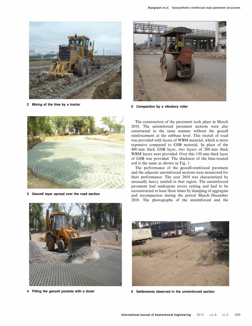
The performance of the geocell-reinforced pavementand the adjacent unreinforced sections were monitored fortheir performance. The year 2010 was characterized byunusually heavy rainfall in that region. The unreinforcedpavement had undergone severe rutting and had to bereconstructed at least three times by dumping of aggregateand recompaction during the period March–December2010. The photographs of the unreinforced and the
2 Mixing of the lime by a tractor
3 Geocell layer spread over the road section
4 Filling the geocell pockets with a dozer
5 Compaction by a vibratory roller
6 Settlements observed in the unreinforced section
Rajagopal et al. Geosynthetic-reinforced road pavement structures
International Journal of Geotechnical Engineering 2014 VOL 8 NO 3 289
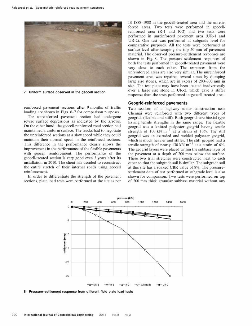
reinforced pavement sections after 9 months of trafficloading are shown in Figs. 6–7 for comparison purposes.
The unreinforced pavement section had undergonesevere surface depressions as indicated by the arrows.On the other hand, the geocell-reinforced road section hadmaintained a uniform surface. The trucks had to negotiatethe unreinforced sections at a slow speed while they couldmaintain their normal speed in the reinforced sections.This difference in the performance clearly shows theimprovement in the performance of the flexible pavementswith geocell reinforcement. The performance of thegeocell-treated section is very good even 3 years after itsinstallation in 2010. The client has decided to reconstructthe entire stretch of their internal roads using geocellreinforcement.
In order to differentiate the strength of the pavementsections, plate load tests were performed at the site as per
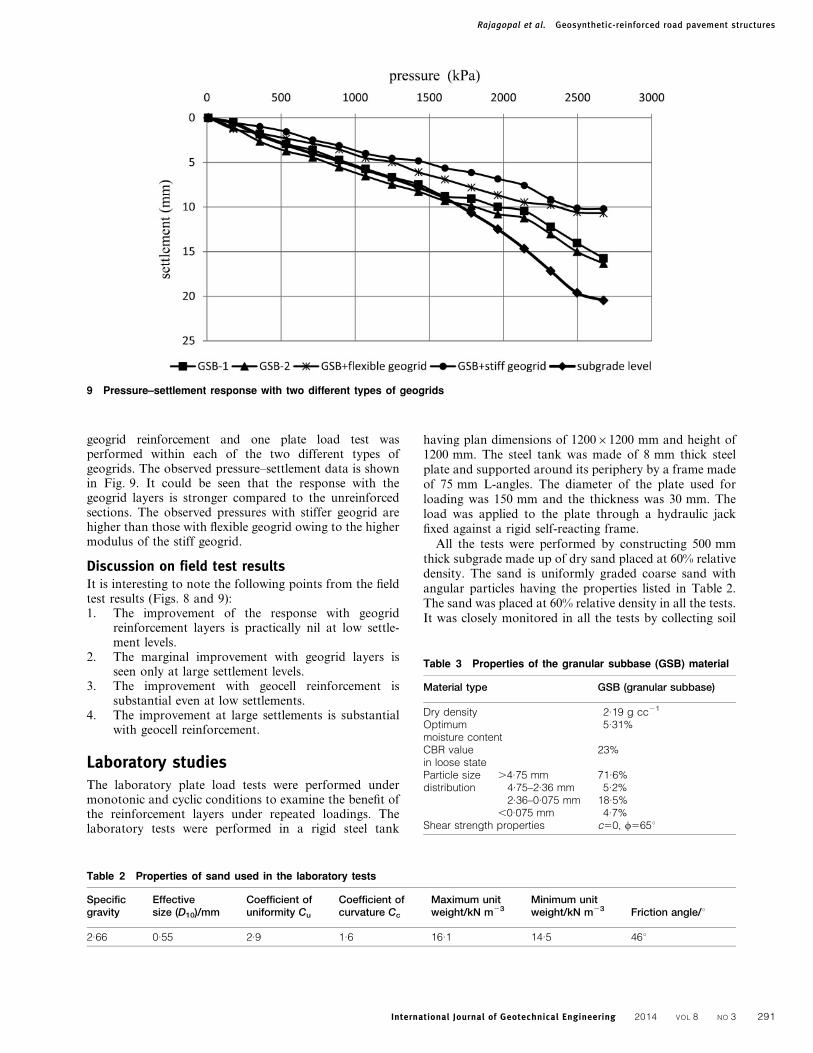
IS 1888–1988 in the geocell-treated area and the unrein-forced areas. Two tests were performed in geocell-reinforced area (R-1 and R-2) and two tests wereperformed in unreinforced pavement area (UR-1 andUR-2). One test was performed at subgrade level forcomparative purposes. All the tests were performed atsurface level after scraping the top 50 mm of pavementmaterial. The observed pressure–settlement responses areshown in Fig. 8. The pressure–settlement responses ofboth the tests performed in geocell-treated pavement werevery close to each other. The responses from theunreinforced areas are also very similar. The unreinforcedpavement area was repaired several times by dumpinglarge size stones, which are in excess of 200–300 mm insize. The test plate may have been located inadvertentlyover a large size stone in UR-2, which gave a stifferresponse than the tests performed in geocell-treated area.
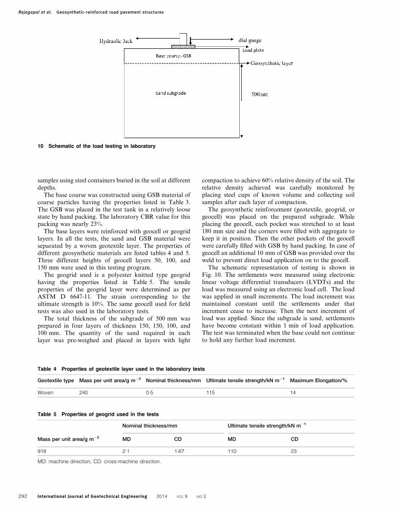
Geogrid-reinforced pavementsTwo sections of a highway under construction nearChennai were reinforced with two different types ofgeogrids (flexible and stiff). Both geogrids are biaxial typehaving tensile strengths in the same range. The flexiblegeogrid was a knitted polyester geogrid having tensilestrength of 100 kN m21 at a strain of 10%. The stiffgeogrid was an extruded and welded polyester geogrid,which is much heavier and stiffer. The stiff geogrid had atensile strength of nearly 130 kN m21 at a strain of 6%.The geogrid layers were placed within the subbase layer ofthe pavement at a depth of 200 mm below the surface.These two trial stretches were constructed next to eachother so that the subgrade soil is similar. The subgrade soilat this site has a soaked CBR value of 8%. The pressure–settlement data of test performed at subgrade level is alsoshown for comparison. Two tests were performed on topof 200 mm thick granular subbase material without any
7 Uniform surface observed in the geocell section
8 Pressure–settlement response from different field plate load tests
Rajagopal et al. Geosynthetic-reinforced road pavement structures
International Journal of Geotechnical Engineering 2014 VOL 8 NO 3290
geogrid reinforcement and one plate load test wasperformed within each of the two different types ofgeogrids. The observed pressure–settlement data is shownin Fig. 9. It could be seen that the response with thegeogrid layers is stronger compared to the unreinforcedsections. The observed pressures with stiffer geogrid arehigher than those with flexible geogrid owing to the highermodulus of the stiff geogrid.
Discussion on field test resultsIt is interesting to note the following points from the fieldtest results (Figs. 8 and 9):1. The improvement of the response with geogrid
reinforcement layers is practically nil at low settle-ment levels.
2. The marginal improvement with geogrid layers isseen only at large settlement levels.
3. The improvement with geocell reinforcement issubstantial even at low settlements.
4. The improvement at large settlements is substantialwith geocell reinforcement.
Laboratory studiesThe laboratory plate load tests were performed undermonotonic and cyclic conditions to examine the benefit ofthe reinforcement layers under repeated loadings. Thelaboratory tests were performed in a rigid steel tank
having plan dimensions of 120061200 mm and height of1200 mm. The steel tank was made of 8 mm thick steelplate and supported around its periphery by a frame madeof 75 mm L-angles. The diameter of the plate used forloading was 150 mm and the thickness was 30 mm. Theload was applied to the plate through a hydraulic jackfixed against a rigid self-reacting frame.
All the tests were performed by constructing 500 mmthick subgrade made up of dry sand placed at 60% relativedensity. The sand is uniformly graded coarse sand withangular particles having the properties listed in Table 2.The sand was placed at 60% relative density in all the tests.It was closely monitored in all the tests by collecting soil
9 Pressure–settlement response with two different types of geogrids
Table 2 Properties of sand used in the laboratory tests
Specificgravity
Effectivesize (D10)/mm
Coefficient ofuniformity Cu
Coefficient ofcurvature Cc
Maximum unitweight/kN m23
Minimum unitweight/kN m23 Friction angle/u
2.66 0.55 2.9 1.6 16.1 14.5 46u
Table 3 Properties of the granular subbase (GSB) material
Material type GSB (granular subbase)
Dry density 2.19 g cc21
Optimummoisture content
5.31%
CBR valuein loose state
23%
Particle sizedistribution
.4.75 mm 71.6%4.75–2.36 mm 5.2%2.36–0.075 mm 18.5%
,0.075 mm 4.7%Shear strength properties c50, w565u
Rajagopal et al. Geosynthetic-reinforced road pavement structures
International Journal of Geotechnical Engineering 2014 VOL 8 NO 3 291
samples using steel containers buried in the soil at differentdepths.
The base course was constructed using GSB material ofcoarse particles having the properties listed in Table 3.The GSB was placed in the test tank in a relatively loosestate by hand packing. The laboratory CBR value for thispacking was nearly 23%.
The base layers were reinforced with geocell or geogridlayers. In all the tests, the sand and GSB material wereseparated by a woven geotextile layer. The properties ofdifferent geosynthetic materials are listed tables 4 and 5.Three different heights of geocell layers 50, 100, and150 mm were used in this testing program.
The geogrid used is a polyester knitted type geogridhaving the properties listed in Table 5. The tensileproperties of the geogrid layer were determined as perASTM D 6647-11. The strain corresponding to theultimate strength is 10%. The same geocell used for fieldtests was also used in the laboratory tests.
The total thickness of the subgrade of 500 mm wasprepared in four layers of thickness 150, 150, 100, and100 mm. The quantity of the sand required in eachlayer was pre-weighed and placed in layers with light
compaction to achieve 60% relative density of the soil. Therelative density achieved was carefully monitored byplacing steel cups of known volume and collecting soilsamples after each layer of compaction.
The geosynthetic reinforcement (geotextile, geogrid, orgeocell) was placed on the prepared subgrade. Whileplacing the geocell, each pocket was stretched to at least180 mm size and the corners were filled with aggregate tokeep it in position. Then the other pockets of the geocellwere carefully filled with GSB by hand packing. In case ofgeocell an additional 10 mm of GSB was provided over theweld to prevent direct load application on to the geocell.
The schematic representation of testing is shown inFig. 10. The settlements were measured using electroniclinear voltage differential transducers (LVDTs) and theload was measured using an electronic load cell. The loadwas applied in small increments. The load increment wasmaintained constant until the settlements under thatincrement cease to increase. Then the next increment ofload was applied. Since the subgrade is sand, settlementshave become constant within 1 min of load application.The test was terminated when the base could not continueto hold any further load increment.
Table 4 Properties of geotextile layer used in the laboratory tests
Geotextile type Mass per unit area/g m22 Nominal thickness/mm Ultimate tensile strength/kN m21 Maximum Elongation/%
Woven 240 0.5 115 14
Table 5 Properties of geogrid used in the tests
Mass per unit area/g m22
Nominal thickness/mm Ultimate tensile strength/kN m21
MD CD MD CD
918 2.1 1.67 110 23
MD: machine direction; CD: cross-machine direction.
10 Schematic of the load testing in laboratory
Rajagopal et al. Geosynthetic-reinforced road pavement structures
International Journal of Geotechnical Engineering 2014 VOL 8 NO 3292
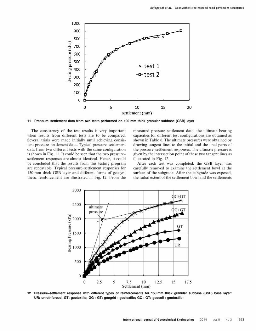
The consistency of the test results is very importantwhen results from different tests are to be compared.Several trials were made initially until achieving consis-tent pressure–settlement data. Typical pressure–settlementdata from two different tests with the same configurationis shown in Fig. 11. It could be seen that the two pressure–settlement responses are almost identical. Hence, it couldbe concluded that the results from this testing programare repeatable. Typical pressure–settlement responses for150 mm thick GSB layer and different forms of geosyn-thetic reinforcement are illustrated in Fig. 12. From the
measured pressure–settlement data, the ultimate bearingcapacities for different test configurations are obtained asshown in Table 6. The ultimate pressures were obtained bydrawing tangent lines to the initial and the final parts ofthe pressure–settlement responses. The ultimate pressure isgiven by the intersection point of these two tangent lines asillustrated in Fig. 12.
After each test was completed, the GSB layer wascarefully removed to examine the settlement bowl at thesurface of the subgrade. After the subgrade was exposed,the radial extent of the settlement bowl and the settlements
11 Pressure–settlement data from two tests performed on 100 mm thick granular subbase (GSB) layer
12 Pressure–settlement response with different types of reinforcements for 150 mm thick granular subbase (GSB) base layer:
UR: unreinforced; GT: geotextile; GGzGT: geogridzgeotextile; GCzGT: geocellzgeotextile
Rajagopal et al. Geosynthetic-reinforced road pavement structures
International Journal of Geotechnical Engineering 2014 VOL 8 NO 3 293
within the bowl were carefully measured. In general, it wasnoticed that the loads are distributed over a larger area ofthe subgrade due to the provision of the geosyntheticlayer. The tests were performed with a single layer ofgeotextile, combination of geotextile and geogrid, and ageocell underlain by a geotextile, which acts as a separatorlayer. The ratio between the diameters of the settlementbowl and the loading plate gives an idea of the pressurestransmitted to the subgrade. These ratios for different testconfigurations are given in Table 7.
It is seen that for geosynthetic-reinforced cases, thediameter of the settlement bowl is much bigger leading tolesser pressures transmitted to the subgrade soil. Thesettlement bowl for the geocell reinforcement is found tobe biggest among all the reinforced cases.
The pavements are subjected to number of loadrepetitions during their service life. The response of thepavements under repeated loading may be much differentfrom that under static loading. Hence, several tests wereperformed by subjecting the pavement sections to repeatedloading (cyclic loading). The loading was applied as one-way cyclic loading. The load was increased to a pre-setmaximum value and reduced to a lower value (1 kN) andincreased once again. The same configurations used forstatic load tests were also used for the cyclic plate loadtests.
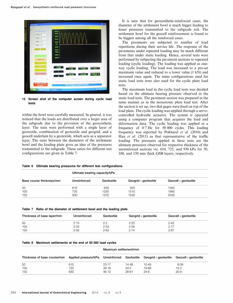
The maximum load in the cyclic load tests was decidedbased on the ultimate bearing pressure observed in thestatic load tests. The pavement section was prepared in thesame manner as in the monotonic plate load test. Afterthe section is set up, two dial gages were fixed on top of theload plate. The cyclic loading was applied through a servo-controlled hydraulic actuator. The system is operatedusing a computer program that acquires the load anddeformation data. The cyclic loading was applied at afrequency of 0?7 Hz for 50 000 cycles. This loadingfrequency was reported by Pokharel et al. (2010) andHan et al. (2011) as that representative of the trafficloading. The pressures applied in these tests are theultimate pressures observed for respective thickness of theunreinforced sections viz. 610, 725, and 930 kPa for 50,100, and 150 mm thick GSB layers, respectively.
13 Screen shot of the computer screen during cyclic load
tests
Table 6 Ultimate bearing pressures for different test configurations
Base course thickness/mm
Ultimate bearing capacity/kPa
Unreinforced Geotextile Geogridzgeotextile Geocellzgeotextile
50 610 630 920 1560100 725 1320 1510 1980150 930 1370 1530 2045
Table 7 Ratio of the diameter of settlement bowl and the loading plate
Thickness of base layer/mm Unreinforced Geotextile Geogridzgeotextile Geocellzgeotextile
50 2.15 2.2 2.25 2.43100 2.33 2.53 2.59 2.77150 2.56 2.62 2.74 2.87
Table 8 Maximum settlements at the end of 50 000 load cycles
Thickness of base course/mm Applied pressure/kPa
Maximum settlement/mm
Unreinforced Geotextile Geogridzgeotextile Geocellzgeotextile
50 610 23.17 14.48 10.49 8.08100 725 39.18 24.5 19.88 15.2150 930 46.12 28.61 24.6 20.9
Rajagopal et al. Geosynthetic-reinforced road pavement structures
International Journal of Geotechnical Engineering 2014 VOL 8 NO 3294
A screen shot of the cyclic loading program is shown inFig. 13. The green line shows the load calculated as per theapplied load and the red line shows the load measured bythe load cell in the actuator. It is seen that both are veryclose to each other.
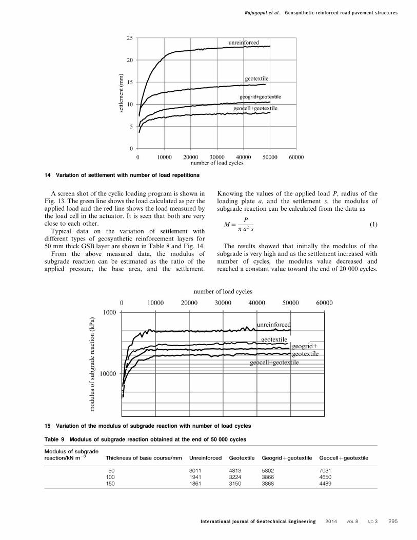
Typical data on the variation of settlement withdifferent types of geosynthetic reinforcement layers for50 mm thick GSB layer are shown in Table 8 and Fig. 14.
From the above measured data, the modulus ofsubgrade reaction can be estimated as the ratio of theapplied pressure, the base area, and the settlement.
Knowing the values of the applied load P, radius of theloading plate a, and the settlement s, the modulus ofsubgrade reaction can be calculated from the data as
M~P
p a2 s(1)
The results showed that initially the modulus of thesubgrade is very high and as the settlement increased withnumber of cycles, the modulus value decreased andreached a constant value toward the end of 20 000 cycles.
14 Variation of settlement with number of load repetitions
15 Variation of the modulus of subgrade reaction with number of load cycles
Table 9 Modulus of subgrade reaction obtained at the end of 50 000 cycles
Modulus of subgradereaction/kN m23 Thickness of base course/mm Unreinforced Geotextile Geogridzgeotextile Geocellzgeotextile
50 3011 4813 5802 7031100 1941 3224 3866 4650150 1861 3150 3868 4489
Rajagopal et al. Geosynthetic-reinforced road pavement structures
International Journal of Geotechnical Engineering 2014 VOL 8 NO 3 295
The typical variation of the subgrade modulus withdifferent number of cycles is shown in Fig. 15 for100 mm thick GSB layer.
The modulus values obtained at the end of 50 000 cyclesare shown in Table 9.The geosynthetic reinforcementimproved the modulus of subgrade reaction of the testsection for all thicknesses of the base course layer. Thereduction in modulus value with increased base layerthickness is due to the compressions within the base layeras it was placed in loose state.
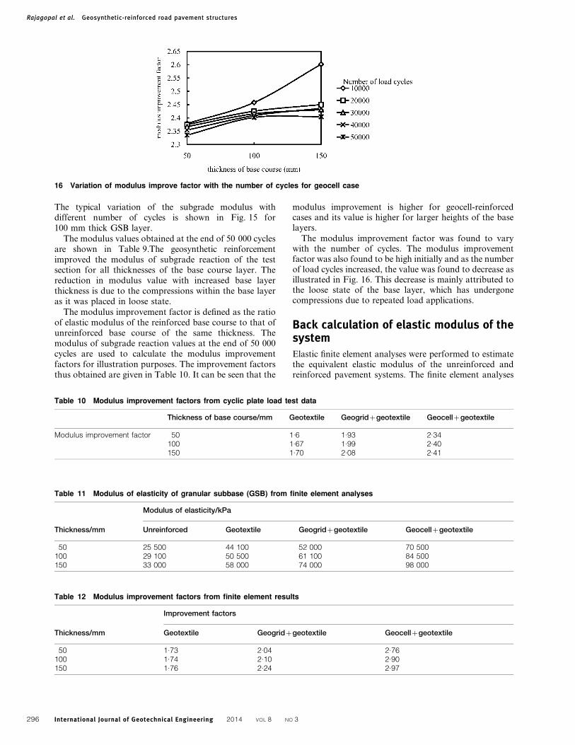
The modulus improvement factor is defined as the ratioof elastic modulus of the reinforced base course to that ofunreinforced base course of the same thickness. Themodulus of subgrade reaction values at the end of 50 000cycles are used to calculate the modulus improvementfactors for illustration purposes. The improvement factorsthus obtained are given in Table 10. It can be seen that the
modulus improvement is higher for geocell-reinforcedcases and its value is higher for larger heights of the baselayers.
The modulus improvement factor was found to varywith the number of cycles. The modulus improvementfactor was also found to be high initially and as the numberof load cycles increased, the value was found to decrease asillustrated in Fig. 16. This decrease is mainly attributed tothe loose state of the base layer, which has undergonecompressions due to repeated load applications.
Back calculation of elastic modulus of thesystemElastic finite element analyses were performed to estimatethe equivalent elastic modulus of the unreinforced andreinforced pavement systems. The finite element analyses
16 Variation of modulus improve factor with the number of cycles for geocell case
Table 10 Modulus improvement factors from cyclic plate load test data
Thickness of base course/mm Geotextile Geogridzgeotextile Geocellzgeotextile
Modulus improvement factor 50 1.6 1.93 2.34100 1.67 1.99 2.40150 1.70 2.08 2.41
Table 11 Modulus of elasticity of granular subbase (GSB) from finite element analyses
Thickness/mm
Modulus of elasticity/kPa
Unreinforced Geotextile Geogridzgeotextile Geocellzgeotextile
50 25 500 44 100 52 000 70 500100 29 100 50 500 61 100 84 500150 33 000 58 000 74 000 98 000
Table 12 Modulus improvement factors from finite element results
Thickness/mm
Improvement factors
Geotextile Geogridzgeotextile Geocellzgeotextile
50 1.73 2.04 2.76100 1.74 2.10 2.90150 1.76 2.24 2.97
Rajagopal et al. Geosynthetic-reinforced road pavement structures
International Journal of Geotechnical Engineering 2014 VOL 8 NO 3296
were performed by using axi-symmetric model and 15-node triangular elements. The rough, rigid footing wassimulated by applying uniform settlements at the nodescorresponding to the footing and restraining their lateraldeformations.
The equivalent elastic modulus was determined by trialand error by matching the finite element calculated footingpressure at 1?5 mm settlement (equal to 1% of platediameter) with the measured pressures in the laboratorytests. It is assumed that the response of the system at asmall settlement equal to 1% of the footing diameter iswithin the elastic limit. The elastic modulus value of thecontinuum was varied until the estimated pressurematches with the experimentally measured values. Theresults of the monotonic plate load tests were used forthese analyses. The elastic modulus values back calculatedfor different cases are listed in Table 11.
The modulus improvement factor for the reinforcedcases is calculated as the ratio between the modulus of thereinforced system and the corresponding modulus of theunreinforced cases. These values are reported in Table 12.It is interesting to note that these improvement factors fallwithin the same range as those estimated using the cyclicload test results. Hence, it may be possible to utilizethe results from static load tests for preliminary designpurposes without incurring too much of an error.However, the designs will not be conservative as themodulus improvement factors from static load tests areabout 15% higher than those from cyclic load tests.
The modulus improvement factors are required inmechanistic-based design of flexible pavements in whichthe modulus values of each pavement layers are to begiven as input values, e.g. CIRCLY program for design ofpavements. These modulus improvement factors can beused to represent the equivalent behavior of the geosyn-thetic-reinforced pavement sections. The use of highermodulus for the pavement layers results in lesser thicknessfor the layers as the pressure transmitted to the subgradereduces with increase in the modulus values. By usingdifferent modulus improvement factors in the CIRCLYprogram, Iniyan (2012) has studied the influence of geocelland geogrid layers on the thickness of the pavement layers.Reduced thickness of the pavement layers results in lessertotal cost of the pavement and lesser construction times.This will also lead to lesser carbon footprint as reducedquantities of natural aggregate materials are required forconstruction.
ConclusionThis paper has presented some results from field andlaboratory tests on the performance of pavements withdifferent types of geosynthetic reinforcements. It is seenthat both the strength and stiffness of the pavement systemcan be improved by the use of geosynthetics. Theperformance under repeated loads is also better withgeosynthetic reinforcement layers.
The improvement in the overall performance is bydistributing the applied loads over a much wider area ofthe subgrade thus reducing the stresses at the subgradelevel. The geocell reinforcement gives much higher
improvement in the pavement performance as comparedto the planar type products like geotextiles and geogrids.
The modulus improvement factors obtained from bothmonotonically applied tests and the cyclic load tests areclose to each other. Significant improvement is observedfor all types of geosynthetic reinforcement systems. Themodulus improvement factor is seen to be higher formonotonic loading as compared to the cyclic load tests.This could be due to the loose packing of the GSB layer inlaboratory tests leading to continuous compressionswithin the GSB layer under cyclic loading.
AckowledgementThe authors are grateful to the support from M/s PRSMediterranean, Tel Aviv, Israel for their support inperforming the field tests at a site near Pune and for thesupply of the geocell materials free of cost.
ReferencesASTM D 0638. 2003. Standard test method for tensile properties of
plastics, West Conshohocken, PA, USA, ASTM International.
ASTM D1204. 2008. Linear dimensional changes of nonrigid thermo-
plastic sheeting or film at elevated temperature, West
Conshohocken, PA, USA, ASTM International.
ASTM D 6392. 2008. Determining the integrity of nonreinforced
geomembrane seams produced using thermo-fusion methods, West
Conshohocken, PA, USA, ASTM International.
ASTM D6647. 2001. Test method for determining tensile properties of
geogrids by the single or multi-rib tensile method, West
Conshohocken, PA, USA, ASTM International.
Bathurst, R. J. and Rajagopal, K. 1993. Large scale triaxial compression
testing of geocell-reinforced granular soils, Geotech. Test. J., 16, 3,
296–303.
Bush, D. I., Jenner, C. G. and Bassett, R. H. 1990. The design and
construction of geocell foundation mattresses supporting embank-
ments over soft ground, Geotext. Geomembr., 9, 83–98.
Chandramouli, S. 2011. Performance and economic evaluation of geocells
in the road pavement structure, Thesis submitted in partial
fulfillment of the requirements of the MTech degree, Department
of Civil Engineering, Indian Institute of Technology Madras,
Chennai, India.
CIRCLY. 2013. Software for design of flexible pavements, Richmond,
VIC, Australia, MINCAD Systems Pvt. Ltd.
Emersleben, A. and Meyer, N. 2010. The influence of hoop stresses and
earth resistance on the reinforcement mechanism of single and
multiple geocells, 9th International Conference on Geosynthetics,
Brazilian Chapter of International Geosynthetics Society, IGC-
2010, Guaruja, Brazil, May 23-27, 713–716.
Giroud, J. P. and Han, J. 2004. Design method for geogrid-reinforced
unpaved roads. I. Development of design method and II. Calibration
of applications, J. Geotech. Geoenviron. Eng., 130, (8), 775–797.
Han, J., Pokharel, S. K., Parsons, R. L., Leshchinsky, D. and Halahmi,
I. 2010. Effect of infill material on the performance of geocell-
reinforced bases, 9th Int. Conf. on ‘Geosynthetics’ (ICG 2010),
Brazil, May 23–27.
Han, J., Pokharel, S. K., Parsons, R. L., Leshchinsky, D. and Halahmi, I.
2010. Effect of infill material on the performance of geocell-
reinforced bases, 9th International Conference on Geosynthetics,
Brazilian Chapter of International Geosynthetics Society ICG 2010,
Guaraja, Brazil, May 23-27, 1503–1506.
Han, J., Yang, X. M., Leshchinsky, D. and Parsons, R. L. 2008. Behavior
of geocell-reinforced sand under a vertical load, J. Transp. Res.
Board, 2045, 95–101.
Iniyan, K. 2012. Influence of geogrid reinforcement on the carbon
footprint of flexible pavements, Thesis submitted in partial
fulfillment of the requirements of the MTech degree, Department
of Civil Engineering, Indian Institute of Technology Madras,
Chennai, India.
Rajagopal et al. Geosynthetic-reinforced road pavement structures
International Journal of Geotechnical Engineering 2014 VOL 8 NO 3 297

IS 1888. 1988. Method of load test on soils, Bureau of Indian Standards,
New Delhi.
Madhavi Latha, G., Dash, S. K. and Rajagopal, K. 2008. Equivalent
continuum simulations of geocell reinforced sand beds supporting
strip footings, Geotech. Geol. Eng., 6, (4), 387–398.
Madhavi Latha, G., Dash, S. K. and Rajagopal, K. 2009 Numerical
simulation of the behaviour of geocell reinforced sand in founda-
tions, ASCE Int. J. Geomech., 9, 143–152.
Parayil, A. 2013. Performance of geosynthetic reinforced flexible
pavements, Thesis submitted in partial fulfillment of the require-
ments of the MTech degree, Department of Civil Engineering,
Indian Institute of Technology Madras, Chennai, India.
Pokharel, S. K., Han, J., Leshchinsky, D., Parsons, R. I. and Halahmi,
I. 2010. Investigation of factors influencing behavior of
single geocell-reinforced based under static loading, Geotext.
Geomembr., 28, 6, 570–578.
Rajagopal, K., Krishnaswamy, N. R. and Madhavi Latha, G. 1999.
Behavior of sand confined with single and multiple geocells,
Geotext. Geomembr., 17, 3, 171–184.
Shin, E. C., Kim, S. H. and Oh, Y. I. 2010. Comparison of bearing
capacity on geocell-reinforced subgrade, 9th International
Conference on Geosynthetics, Brazilian Chapter of International
Geosynthetics Society, IGC-2010, Guaruja, Brazil, May 23-27,
1441–1444.
Unni, A. 2010. Structural and economic evaluation of geocells in the road
pavement structure, Thesis submitted in partial fulfillment of the
requirements of the MTech degree, Department of Civil Engineering,
Indian Institute of Technology Madras, Chennai, India.
Rajagopal et al. Geosynthetic-reinforced road pavement structures
International Journal of Geotechnical Engineering 2014 VOL 8 NO 3298