structural vibration control using extension and shear ... · structural vibration control using...
TRANSCRIPT

Structural Vibration Control Using Active-Passive Piezoelectric Networks Including Sensitivity to Electrical Uncertainties
Heinsten F. L. dos [email protected]
Department of Mechanical EngineeringSao Carlos School of Engineering
University of Sao Paulo13566-590 Sao Carlos, SP, Brazil
Marcelo A. [email protected]
Department of Mechanical EngineeringSao Carlos School of Engineering
University of Sao Paulo13566-590 Sao Carlos, SP, Brazil
Structural Vibration Control UsingExtension and Shear Active-PassivePiezoelectric Networks IncludingSensitivity to Electrical UncertaintiesActive-Passive Piezoelectric Networks (APPN) integrate active voltage sources with passiveresistance-inductance shunt circuits to a piezoelectric patch. This technique allows tosimultaneously passively dissipate vibratory energy through the shunt circuit and activelycontrol the structural vibrations. This work presents an analysis of active-passive dampingperformance of beams with extension and shear APPN. A coupled finite element model withmechanical and electrical degrees of freedom is developed and used to design passive andactive control parameters. Then, stochastic modeling and analyses of two cantilever beamconfigurations, with extension and shear APPN, are performed to evaluate the effect ofuncertainties in circuit components on passive and active-passive vibration control. Resultsshow that active-passive shunt circuits can be very interesting since they may combinean adequate passive control performance with an increase of active control authoritywhen a control voltage is applied to the circuit. For the extension configuration, vibrationamplitude reductions of up to 22 dB and 28 dB are obtained for passive and active-passivecases, respectively. Considering relative dispersions of 10% for the resistance andinductance values, the passive and active-passive amplitude reductions are found to be inthe ranges 16-24 dB and 27-28 dB, respectively. For the shear configuration, increasesin the active control authority of up to 29 dB due to a properly tuned resonant circuit areobserved. When subjected to uncertainties in the resistance and inductance values, with10% relative dispersions, the control authority increase is in the range of 6-29 dB.Keywords: piezoelectric materials, active-passive piezoelectric networks, vibration control,stochastic modeling, uncertainty analysis
Introduction
Due to their strong electromechanical coupling, piezoelectricmaterials have been widely used as sensors and actuators for structuralvibration control. They can be used either as actuators connectedto an appropriate control law to provide active vibration control oras sensors connected to shunt circuits to provide passive damping.In the last decade, research was redirected to combined active andpassive vibration control techniques. One of these techniques, so-called Active-Passive Piezoelectric Networks (APPN), integrates anactive voltage source with a passive resistance-inductance shuntcircuit to a piezoelectric sensor/actuator (Tsai and Wang, 1999). Inthis case, the piezoelectric material serves two purposes. First, thevibration strain energy of the structure can be transferred to the shuntcircuit, through the difference of electric potential induced in thepiezoelectric material electrodes, and then passively dissipated in theelectric components of the shunt circuit (Forward, 1979; Hagood andvon Flotow, 1991, Viana and Steffen, 2006). On the other hand,the piezoelectric material may also serve as an actuator for whicha control voltage can be applied to actively control the structuralvibrations. This active mechanism combined to a velocity feedback,for instance, may then induce an additional active damping in thestructure.
There are still some unresolved issues concerning this active-passive damping mechanism, such as for which conditionssimultaneous active-passive damping outperforms separate active andpassive mechanisms, that is, whether the control voltage should bepart of the shunt circuit or not (Thornburgh and Chattopadhyay,2003). It has been shown that combined active-passive vibrationcontrol allows better performance with smaller cost than separateactive and passive control, provided the simultaneous action is
Paper received 5 August 2010. Paper accepted 5 February 2011.Technical Editor: Francisco Cunha
optimized (Tsai and Wang, 1999). On the other hand, like for purelypassive shunted piezoelectric damping, most of the studies concerningAPPN focus on the optimization of the electric circuit architectureand components. It is well-known, however, that the performance ofboth active and passive damping mechanisms is highly dependent onthe effective electromechanical coupling provided by the piezoelectricactuators/sensors. Nevertheless, few studies focus on the optimizationof this coupling for given structure and piezoelectric material. Inparticular, it has been shown that piezoelectric actuators using theirthickness-shear mode can be more effective than surface-mountedextension piezoelectric actuators for both active (Trindade, Benjeddouand Ohayon, 1999; Raja, Prathap and Sinha, 2002; Baillargeon andVel, 2005; Trindade and Benjeddou, 2006) and passive (Benjeddouand Ranger-Vieillard, 2004; Benjeddou, 2007; Trindade and Maio,2008) vibration damping. One of the reasons for that is the thickness-shear electromechanical coupling coefficient k15 that is normallytwice the value of the extension one, k31, which may lead to ahigher effective electromechanical coupling coefficient (Trindade andBenjeddou, 2009). The thickness-shear mode, originally proposedby Sun and Zhang (1995), can be obtained using longitudinally-poled piezoelectric patches that couple through-thickness electricfields/displacements and shear strains/stresses. On the other hand,although it is well-known that the performance of shunt circuitsis quite sensible to the tuning of circuit parameters, little hasbeen published about the complexities in tuning the electric circuitparameters and the effect of the parametric variations on the overallperformance of the system (Viana and Steffen, 2006; Andreaus andPorfiri, 2007).
This work presents the modeling of sandwich structureswith APPN using extension and thickness-shear piezoelectricsensors/actuators. The model is based on a stress-voltageelectromechanical model for the piezoelectric materials fully coupledwith the APPN active-passive circuit. To this end, the APPN
J. of the Braz. Soc. of Mech. Sci. & Eng. Copyright c© 2011 by ABCM July-September 2011, Vol. XXXIII, No. 3 / 287

Heinsten F.L. dos Santos and Marcelo A. Trindade
circuit equations are also included in the variational formulation.Hence, conservation of charge and full electromechanical couplingare guaranteed. The formulation results in a coupled finite elementmodel with mechanical (displacements) and electrical (electrodescharges) degrees of freedom. An analysis of the resulting coupledequations of motion is performed to identify the damping mechanismsprovided by an active-passive piezoelectric network. Then, stochasticmodeling and analysis of two cantilever beam configurations, withextension and shear piezoceramics, are performed to account foruncertainties in circuit components. This work includes an originalmodeling and analysis of APPN using shear response mode ofpiezoelectric materials and also an original sensitivity analysis ofpassive and active-passive shunted piezoelectric damping using astochastic model.
Nomenclature
A = cross-sections or electrodes areab = perturbation input distribution vectorC = damping matrixc = output distribution vectorcDk
11 = effective elastic stiffness constant of surface layer kcDc
33 = effective elastic stiffness constant of core layerD = vector of electric displacements dofD3 = transverse electric displacementE3 = transverse electric fieldF = vector of generalized mechanical forcesf = amplitude of perturbation inputGc = control authority of pair patch and shunt circuitGh = FRF for beams with active-passive shunt circuitsGp = FRF for beams with passive shunt circuitsg = vector of control gainsH = electric enthalpyhk
31 = effective piezoelectric constant of surface layer khc
15 = effective piezoelectric constant of core layerh = thicknessI = second moment of cross-section areaK = stiffness matrixK = modified stiffness matrixke = effective stiffness coefficient of pair patch-circuitkp = effective piezoelectric stiffness of vibration mode of interestL = length of the beamLc j = inductance of circuit jM = mass matrixmq = effective inertia coefficient of pair patch-circuitpX = probability density function of random variable Xqc = vector of electric charges generated at piezo-patchesRc j = resistance of circuit ju = vector of nodal mechanical displacementsu = axial displacementT = kinetic energyVc j = voltage source applied to circuit jW = work done by dissipative forcesw = transverse displacementy = mechanical response output
Greek Symbols
αn = modal displacement of vibration mode of interestβεk33 = effective dielectric constant of surface layer kβεc11 = effective dielectric constant of core layerβi = cross-section rotation angleδ = virtual variation operatorδX = relative dispersion of random variable Xε1 = normal strainε5 = shear strainφn = vibration mode of interestω = resonance frequencyρi = mass density of layer iσ1 = normal stressσ5 = shear stressσX = standard deviation of random variable X
Subscripts
c = relative to electric shunt circuitse = relative to dielectric contributions or electric circuiti = relative to layer ij = relative to circuit jL = relative to shunt circuit inductancem = relative to mechanical contributionsme = relative to piezoelectric contributionsn = relative to vibration mode np = relative to piezoelectric patch pq = relative to electric displacement dofsR = relative to shunt circuit resistance
Superscripts
c = relative to core layer or shear strainD = for constant electric displacementε = for constant strainf = relative to bending straink = relative to surface layer km = relative to membrane strainOC = relative to open-circuited shunt circuitR = relative to resistive shunt circuitRL = relative to resonant shunt circuitSC = relative to short-circuited shunt circuitV = relative to voltage source only
Finite Element Model of a Piezoelectric Sandwich Beam
Consider a sandwich beam made of piezoelectric layers andmodeled using a classical sandwich theory. Surface layers are madeof transversely poled piezoelectric materials, whereas the core layeris made of longitudinally poled piezoelectric materials. Electrodesfully cover the top and bottom skins of all layers so that onlythrough-thickness electric field and displacement are considered.For simplicity, all layers are assumed to be made of orthotropicpiezoelectric materials, perfectly bonded and in plane stress state.Bernoulli-Euler theory is retained for the sandwich beam surfacelayers, while the core is assumed to behave as a Timoshenko beam.The length, width and thickness of the beam are denoted by L, b andh, respectively.
288 / Vol. XXXIII, No. 3, July-September 2011 ABCM
Structural Vibration Control Using Active-Passive Piezoelectric Networks Including Sensitivity to Electrical Uncertainties
Displacements and strains
The axial and transverse displacement fields of faces and coremay be written in the following general form:
ui(x,y,z) = ui(x)+(z− zi)βi(x) , i = t,c,b,
vi(x,y,z) = 0,
wi(x,y,z) = w(x),
(1)
where ui is the mid-plane axial displacement of the layer i (i= t for thetop layer, i = c for the core layer and i = b for the bottom layer). βi isthe cross-section rotation angle and from Bernoulli-Euler assumptionsβt = βb =−w′, where w′ states for ∂w/∂x. zi states for the positionof the layer i mid-plane in the global transversal z direction. Using thedisplacement continuity conditions between layers, the displacementfields may be written in terms of only three main variables, ut , ub andw, so that uc and βc are written as
uc =ut +ub
2+
hd
4w′ and βc =
ut −ub
hc+
hm
hcw′, (2)
with hm and hd being the mean and difference of the surface layersthicknesses, ht and hb:
hm =ht +hb
2and hd = ht −hb. (3)
The usual strain-displacement relations for each layer yield thefollowing axial and shear strains for the layer i:
ε1i =∂ ui
∂x= εm
i +(z− zi)εfi and ε5i =
∂ ui
∂ z+
∂ wi
∂x= εc
i , (4)
while the remaining strainsε2i, ε3i, ε4i andε6i vanish. The membrane,bending and shear generalized strains, εm
i , ε fi and εc
i , can be writtenas
εmk = u′k, ε
fk =−w′′, εc
k = 0, for surface layers (k = t,b), (5)
εmc =
u′t +u′b2
+hd
4w′′, ε f
c =u′t −u′b
hc+
hm
hcw′′,
εcc =
ut −ub
hc+
(hm
hc+1)
w′.(6)
Alternatively, these expressions can be written in terms ofthe mean and relative axial displacements, instead of the axialdisplacements of the top and bottom layers, as done in previous works(Benjeddou, Trindade and Ohayon, 1999; Trindade, Benjeddou andOhayon, 2001).
Piezoelectric constitutive equations
Linear orthotropic piezoelectric materials with material symmetryaxes parallel to the beam ones are considered here. The constitutiveequations for these materials can be obtained starting from the generalexpression for the electric enthalpy of a piezoelectric layer
H(ε,D) =12εtcDε−εthtD+
12
DtβεD, (7)
such that
σ = ∂H/∂ε = cDε−htD,
E = ∂H/∂D =−hε+βεD,(8)
where cDi j, hl j and βεl (i, j = 1, ...,6; l = 1,2,3) denote the elastic
(for constant electric displacement), piezoelectric and dielectric (forconstant strain) constants of the piezoelectric material, respectively.
For both extension and shear mode piezoelectric layers, onlytransverse electric field and displacements are considered (D1 =D2 =0) since the layers have electrodes on top and bottom skins. However,faces and core layers are treated separately, since they have differentpoling directions. An additional assumption of plane stress state(σ3 = 0) allows to write the following reduced constitutive equationsfor the faces and the core:
σ1kE3k
=
[cDk
11 −hk31
−hk31 βεk33
]ε1kD3k
, (9)
andσ1cσ5cE3c
=
cDc33 0 00 cDc
55 −hc15
0 −hc15 βεc11
ε1cε5cD3c
, (10)
where,
cDk11 = cDk
11 −cDk
132
cDk33
, hk31 = hk
31−hk33
cDk13
cDk33
, βεk33 =βεk33 +
hk33
2
cDk33
, (11)
cDc33 = cDc
33 −cDc
132
cDc11
. (12)
Finite element discretization
Lagrange linear shape functions are assumed for the axialdisplacements, ut and ub, and electric displacements in each layer,D3t , D3c and D3b. For the transverse deflection w, Hermite cubicshape functions are assumed. These assumptions lead to a two nodefinite element with four mechanical dof and three electrical dof pernode. The elementary mechanical degrees of freedom (dof) columnvector un is defined as
un = [u(1)t u(1)b w(1) w′(1) u(2)t u(2)b w(2) w′(2)]t. (13)
The axial and transverse displacements of the face layers can bewritten in terms of the elementary dofs as
uk = Nxkun, w = Nzun, k = t,b, (14)
where
Nxt =[N1 0 0 0 N2 0 0 0
],
Nxb =[0 N1 0 0 0 N2 0 0
],
Nz =[0 0 N3 N4 0 0 N5 N6
],
(15)
and
J. of the Braz. Soc. of Mech. Sci. & Eng. Copyright c© 2011 by ABCM July-September 2011, Vol. XXXIII, No. 3 / 289

Heinsten F.L. dos Santos and Marcelo A. Trindade
N1 = 1− xL, N2 =
xL, N3 = 1− 3x2
L2 +2x3
L3 , N4 = x(
1− xL
)2,
N5 =x2
L2
(3− 2x
L
), N6 =
x2
L
( xL−1).
(16)
The axial displacement of the core layer uc and the cross-sectionrotations βi can then be written, using βt =βb =−w′ and (2), as
uc = Nxcun, βi = Nriun, i = t,c,b, (17)
where
Nxc =Nxt +Nxb
2+
hd
4N′z, Nrc =
Nxt −Nxb
hc+
hm
hcN′z,
Nrt = N′xt , Nrb = N′xb.
(18)
According to expressions (5) and (6) for the generalized strains,εm
i , ε fi , and εc
i , they can be written in terms of the elementary dofs as
εmi = Bmiun, ε
fi = B f iun, ε
cc = Bccun. (19)
The membrane, bending and shear strain operators Bmi, B f i andBcc are defined as
Bmi = N′xi, B f i = N′ri, Bcc = Nrc +N′z. (20)
The elementary electric dofs column vector Dn is defined as
Dn =[D(1)
3t D(1)3c D(1)
3b D(2)3t D(2)
3t D(2)3b
]t. (21)
Then, the electric displacement in the piezoelectric layers can bewritten in terms of the elementary dofs
D3i = NDiDn, i = t,c,b, (22)
where
NDt =[N1 0 0 N2 0 0
],
NDc =[0 N1 0 0 N2 0
],
NDb =[0 0 N1 0 0 N2
].
(23)
Variational formulation
The equation of motions can be written using the Hamilton’sprinciple extended to piezoelectric media
δΠb =∫
t
[∑
i(δTi−δHi)+δWm
]dt = 0, (24)
where δTi, δHi and δWm are the virtual variations of kinetic energy Tiand electric enthalpy Hi of layer i and the total virtual work done bymechanical forces on the structure.
The virtual variation of kinetic energy for layer i of the sandwichbeam can be written using the displacements fields defined in (1) andsupposing that all layers are symmetric with respect to their neutrallines, z = zi, such that integration over the cross-section areas leads to
∫tδTidt =−
∫t
∫ L
0
[ρiAi (δuiui +δww)+ρiIiδβiβi
]dx dt, (25)
where ρi is the mass density and Ai and Ii are the area and secondmoment of area of the cross-section of layer i, respectively, and thedot stands for time derivation.
Using the finite element discretization of generalizeddisplacements (14) and (17),
∫tδTidt =−
∫tδut
nMiun dt, (26)
where Mi is mass matrix of the layer i defined as
Mi =∫ L
0
[ρiAi(Nt
xiNxi +NtziNzi)+ρiIiNt
riNri]
dx. (27)
The virtual variation of the electric enthalpy Hi for each layer willbe composed of mechanical δHmi, electromechanical (piezoelectric)δHmei, and dielectric δHei contributions. In what follows, these aredetailed for the faces i = t,b and core i = c layer.
For the core layer, both normal and shear strains contribute to thevirtual variation of electric enthalpy, while for the faces only normalstrains are relevant. Then, using (4) and supposing symmetric layers,the integration over the cross-section reduces δHmi to
δHmk =∫ L
0
(δεm
k cDk11 Akε
mk +δε
fk cDk
11 Ikεfk
)dx, k = t,b,
δHmc =∫ L
0
(δεm
c cDc33 Acε
mc +δε
fc cDc
33 Icεfc +δε
cckccDc
55 Acεcc
)dx,
(28)
where kc is a shear correction factor for the Timoshenko core layer.Also supposing symmetric layers and integrating in the cross-
section, the piezoelectric contributions to the virtual variation ofelectric enthalpy can be written as
δHmek =−∫ L
0
(δεm
k hk31AkD3k +δD3khk
31Akεmk
)dx,
δHmec =−∫ L
0(δεc
chc15AcD3c +δD3chc
15Acεcc)dx.
(29)
Notice that the piezoelectric effect couples the transversal electricdisplacement D3i with membrane and bending strains εm
k and ε fk , for
the faces, and with shear strain εcc, for the core.
The dielectric contribution to the virtual variation of electricenthalpy can be written as
δHek =∫ L
0δD3kβ
εk33AkD3kdx, δHec =
∫ L
0δD3cβ
εc11AcD3cdx.
(30)
The mechanical, piezoelectric and dielectric contributions to thevirtual variation of electric enthalpy can be written in a discrete
290 / Vol. XXXIII, No. 3, July-September 2011 ABCM

Structural Vibration Control Using Active-Passive Piezoelectric Networks Including Sensitivity to Electrical Uncertainties
form substituting the discretized generalized strains (19) and electricdisplacements (22) in equations (28), (29) and (30), such that
δHmi = δutnKmiun, δHmei =−δut
nKmeiDn−δDtnKt
meiun,
δHei = δDtnKeiDn,
(31)
where Kmi are the elastic stiffness matrices of the layer i written as
Kmk =∫ L
0
(Bt
mk cDk11 AkBmk +Bt
f k cDk11 IkB f k
)dx,
Kmc =∫ L
0
(Bt
mccDc33 AcBmc +Bt
f ccDc33 IcB f c +Bt
cckccDc55 AcBcc
)dx,
(32)
Kmei states for the electromechanical (piezoelectric) stiffness matrices
Kmek =∫ L
0
(Bt
mkhk31AkNDk
)dx,
Kmec =∫ L
0
(Bt
cch15AcNDc)
dx,(33)
and Kei are the dielectric stiffness matrices
Kek =∫ L
0
(Nt
Dkβεk33AkNDk
)dx,
Kec =∫ L
0
(Nt
Dcβεc11AcNDc
)dx.
(34)
The virtual work done by external mechanical forces can bewritten in terms of a vector of generalized mechanical forces F suchthat
δWm = δutnF. (35)
Replacing the discretized virtual work expressions in theHamilton’s principle (24) and assembling for all finite elements inthe structure, the global equations of motion can be expressed as
[M 00 0
]uD
+
[Km −Kme−Kt
me Ke
]uD
=
F0
, (36)
where u and D are the global mechanical and electric dofs andthe mass and stiffness matrices and mechanical force vector wereassembled for all layers and all finite elements.
Connecting Piezoelectric Patches to Electrodes andElectric Circuits
To account for the electrodes fully covering the piezoelectricpatches top and bottom skins, the electric displacements of selectednodes and layers are set to be equal. This dof assignment can berepresented by the following expression:
D = LpDp , Dp =[Dp1 Dp2 · · · Dpn
]t (37)
where Lp is a binary matrix and Dp is a vector of the electricdisplacement for one piezoelectric patch (constant throughout the
electrode surface). Substituting (37) into the variational form of (36),the equations of motion are reduced to
[M 00 0
]u
Dp
+
[Km −Kme−Kt
me Ke
]u
Dp
=
F0
, (38)
where
Kme = KmeLp , Ke = LtpKeLp. (39)
In addition, it is supposed that each piezoelectric actuator/sensorcan be connected to an electric circuit composed of an inductance Lc j ,a resistance Rc j and a voltage source Vc j in series, with j = 1, ...,nwhere n is the number of electric circuits. The equations of motionfor the circuits can be written using the Hamilton’s principle also as
δΠc =∫
t
n
∑j=1
(δTc j +δWr j +δWe j) dt = 0 (40)
where δTc j, δWr j and δWe j are, respectively, the virtual variation ofthe kinetic energy due to the inductances Lc j and the virtual workdone by the resistances Rc j and voltage sources Vc j connected inseries for the j-th electric circuit. These are written as
∫tδTc j dt =−
∫tδqt
c jLc j qc j dt, δWr j =−δqtc jRc jqc j,
δWe j = δqtc jVc j, j = 1, . . . ,n.
(41)
To account for the connection between piezoelectric patches andelectric circuits, it is supposed that electric charges entering a givenelectric circuit are equal to electric charges of a given piezoelectricpatch. Since, due to equipotentiality condition in the electrodes, theelectric displacement is constant throughout the electrode surface,the electric charges for a given piezoelectric patch is obtained bymultiplying the electric displacement by the electrode area. Thus, adiagonal matrix Ap with elements that are the electrodes areas of eachpiezoelectric patch is defined. Then, the vector of electric chargesgenerated at the piezoelectric patches and, thus, entering the n electriccircuits can be written as
qc = ApDp (42)
Including the virtual works of (41) in the variational form of theequations of motion (38) leads to
δut (Mu+Kmu− KmeDp−F)+δDt
p(−Kt
meu+ KeDp)
+δqtc (−Lcqc−Rcqc +Vc) = 0. (43)
Accounting for the relation between circuits’ electric charges andpatches’ electric displacements (42), the structure-patches-circuitscoupled equations of motion can then be written as
[M 00 Mq
]u
Dp
+
[C 00 Cq
]u
Dp
+
[Km −Kme−Kt
me Ke
]u
Dp
=
FFq
, (44)
where Mq = AtpLcAp, Cq = At
pRcAp, Fq = AtpVc and a structural
damping matrix C can be added a posteriori.
J. of the Braz. Soc. of Mech. Sci. & Eng. Copyright c© 2011 by ABCM July-September 2011, Vol. XXXIII, No. 3 / 291

Heinsten F.L. dos Santos and Marcelo A. Trindade
Passive and Active Vibration Control Design
From (44), it is possible to observe that the shunt circuit canaffect the structural response either passively through coupling ofthe dynamics of circuit and structure, via the piezoelectric patches,or actively through the application of an electric voltage in thecircuit which excites the structure, also via the piezoelectric patches.These effects can be better observed in a frequency response function(FRF) of the structure when subjected to a mechanical or electricalexcitation.
For a purely mechanical excitation, such that Vc = 0 and F =b f ejωt , the amplitude of a displacement output y = cu can be writtensuch that y = Gp(ω) f , where the FRF Gp(ω) is
Gp(ω) = c−ω2M+ jωC+Km
− Kme(−ω2Mq + jωCq + Ke)−1Kt
me−1b, (45)
from which it is possible to notice that the resistance and inductancehave the effect of changing the dynamic stiffness of the structure. Twoparticular cases of interest can be derived: i) open-circuit when Cq→∞ and ii) short-circuit when Mq = Cq = 0, in which cases
GOCp (ω) = c
−ω2M+ jωC+Km
−1b,
GSCp (ω) = c
−ω2M+ jωC+Km− KmeK−1
e Ktme
−1b.
(46)
As expected, no structural modification is observed in the open-circuit case while, for the short-circuit case, the stiffness of thepiezoelectric patches is reduced.
For a purely electric excitation using a single pair patch-circuit,such that F = 0 and Vc = Vcejωt , the FRF between the output y andthe applied voltage Vc is such that y = Gc(ω)Vc, where
Gc(ω) = c−ω2M+ jωC+Km
− Kme(−ω2Mq + jωCq + Ke)−1Kt
me−1
× Kme(−ω2Mq + jωCq + Ke)−1At
p (47)
In this case, the resistance and inductance of the electric circuithave two effects. The first is a modification on the dynamic stiffnessof the structure as in the previous case. The second is a modificationof amplitude of the equivalent force input induced in the structureby the applied voltage, which for a properly adjusted circuit can leadto a desirable amplification of the control authority of the pair patch-circuit. The particular case of a simple voltage actuator can be derivedby making Mq = Cq = 0, for which
GVc (ω)= c
−ω2M+ jωC+Km− KmeK−1
e Ktme
−1KmeK−1
e Atp
(48)
Passive vibration control using electromechanical vibrationabsorbers
Starting from the equations of motion (44) for the case of asingle passive electric shunt circuit (RL) connected to a piezoelectricpatch embedded in the structure, it is desired to apply the theory
of dynamic vibration absorbers for a particular vibration mode ofinterest. Therefore, the structural response is approximated by thecontribution of a single vibration mode of interest such that
u(t) =φnαn(t), (49)
where φn and αn are the vibration mode of interest and itscorresponding modal displacement. Thus, neglecting the structuraldamping, the equations of motion for the resulting two degree offreedom system can be written as
αn +ω2nαn− kpDp = bn f ,
mqDp + cqDp + keDp− kpαn = 0,(50)
whereφtnMφn = 1,φt
nKmφn =ω2n, kp =φ
tnKme and bn =φ
tnb.
Assuming a mechanical excitation through input f , the structuralresponse measured by a displacement output y = cnαn, where cn =cφn, can be written such that its amplitude is y = Gp(ω) f , where theamplitude of the FRF Gp(ω) is
|Gp(ω)|= cnbn
[(−ω2mq + ke)
2 +(ωcq)2]1/2×
[ω4mq−ω2(ke +mqωn2)+ keωn
2− kp2]2
+[(−ω2 +ωn2)ωcq]
2−1/2
. (51)
For limited values of cq, |Gp(ω)| has an anti-resonance at a frequencyequal to the resonance frequency of the electrical circuit, definedas ωe = (ke/mq)
1/2, which can be designed to match the structuralresonance of interestωn. This leads to an expression for mq, and thusfor the inductance Lc, in terms ofωn, such that
Lc =ke
ω2nA2
p, (52)
where Ap is the surface area of the electrode covering the piezoelectricpatch connected to the circuit. From the theory of dynamic vibrationabsorbers, it is known that the anti-resonance is accompanied by tworesonances which may have their amplitudes controlled by the electriccircuit damping cq. One strategy to design the damping parameter isto minimize the difference between the resonances and anti-resonanceamplitudes. This can be done by first using limcq→0 |Gp(ω)|2 =
limcq→∞ |Gp(ω)|2 to find the frequencies for which the amplitude isindependent of damping parameter which are
ω21,2 =
12
[ω2
e +ω2n±√
(ω2e −ω2
n)2 +2ω2
e(k2p/ke)
]. (53)
Equalizing the vibration amplitudes at one of these invariantfrequencies ω1 and at the anti-resonance frequency ωn leads to anexpression for the resistance Rc in terms of the equivalent couplingstiffness kp, electrical stiffness ke, surface area of the electrode Apand structural resonance frequency of interestωn,
Rc =kp√
2ke
ω2nA2
p. (54)
292 / Vol. XXXIII, No. 3, July-September 2011 ABCM

Structural Vibration Control Using Active-Passive Piezoelectric Networks Including Sensitivity to Electrical Uncertainties
Active vibration control using piezoelectric actuators and statefeedback
A state feedback LQR (Linear Quadratic Regulator) optimalcontrol is considered. For that, it is necessary to rewrite the equationsof motion (44) in state space form, such that a vector of state variablesz is defined, containing the modal displacements and velocities of aseries of vibration modes of interest and the electric displacements ofthe piezoelectric patches and their time-derivatives. This leads to
z = Az+ BVc + B f f , y = Cyz, (55)
where
z =
α
Dpα
Dp
, A =
0 0 I 00 0 0 I−Ω 2 Kp −Λ 0
M−1q Kt
p −Ω 2e 0 −Λe
,
B =
000
M−1q At
p
, B f =
00
bφ0
, Cy =[cφ 0 0 0
].
(56)
The modal displacements are such that u =Φα and, for massnormalized vibration modes, Ω 2 =ΦtKmΦ and Λ =ΦtCΦ. Ωis a diagonal matrix which elements are the undamped naturalfrequencies of the structure with piezoelectric patches in open-circuit.Ω 2
e = M−1q Ke and Λe = M−1
q Cq are both diagonal matrices whichelements stand, respectively, for the squared natural frequencies of theelectric circuits and the ratio between the resistances and inductances(M−1
q Cq = L−1c Rc). The electromechanical coupling stiffness matrix
projected in the undamped modal basis is defined as Kp =ΦtKme.Input b and output c distribution vectors are also defined, with modalprojections bφ =Φtb and cφ = cΦ, and f is a vector of the amplitudesof each mechanical force applied to the structure.
A linear state feedback for the applied voltages Vc is assumedsuch that Vc = −gz = −gdmα− gdeDp− gvmα− gveDp, where g isa vector of control gains for each state variable. Therefore, the statespace equation (55) becomes
z = (A− Bg)z+ B f f , y = Cyz. (57)
For a single-input mechanical excitation f , the closed-loop orcontrolled amplitude of a single displacement output y can be writtensuch that y = Gh(ω) f , where the FRF Gh(ω) is
Gh(ω) = Cy(jωI− A+ Bg)−1B f , (58)
which can also be derived from the second order equations of motionprojected into the undamped modal basis leading to
Gh(ω) = cφ−ω2I+ jω(Λ+KpD−1
cc Atpgvm)
+ [Ω 2 +KpD−1cc (At
pgdm−Ktp)]−1bφ, (59)
where the closed-loop dynamic stiffness of the electric circuit Dcc is
Dcc =−ω2Mq + jω(Cq +Atpgve)+(Ke +At
pgde). (60)
In this work, the control gain g is calculated using the standardoptimal LQR control theory applied to a single-input/single-outputcase, that is, with only one active-passive patch-circuit pair for thecontrol to minimize the vibration amplitude at one specific location ofthe structure, such that the following objective function is minimized:
J =12
∫∞
0
(y2 + rV 2
c
)dt, (61)
where y is the velocity at one location of interest and Vc is the controlvoltage applied to the active-passive shunt circuit. The weightingfactor r is automatically adjusted to guarantee a maximum controlvoltage of 200 V in all cases following an iterative routine proposedin (Trindade, Benjeddou and Ohayon, 1999).
Results and Discussion
In this section, the FRFs of two cantilever beam configurations,with extension and shear piezoceramics as shown in Figure 1, areanalyzed in order to evaluate the APPN performance in terms ofpassive damping, control authority and active-passive damping. Theextension and shear piezoceramics are made of PZT-5H materialwhose properties are: cD
11 = 97.767 GPa, cD33 = 119.71 GPa, cD
55 =
42.217 GPa, ρ= 7500 kg m−3, piezoelectric coupling constants h31 =−1.3520 109 N C−1 and h15 = 1.1288 109 N C−1, and dielectricconstants βε33 = 57.830 106 m F−1 and βε11 = 66.267 106 m F−1.For the Aluminium beam, material properties are: Young’s modulus70.3 GPa and density 2710 kg m−3 and, for the foam, Young’smodulus 35.3 MPa, shear modulus 12.7 MPa and density 32 kg m−3.A viscous damping of 0.5% and a shear correction factor kc = 0.83were considered.
25220
3.00.5
Piezoceramic Aluminum
10
LRsourceVoltage
Shunt circuit
Output
External input
Control input
(a)
25220
3.00.5
Piezoceramic Aluminum
Aluminum 3.0
Foam
10
LRsourceVoltage
Shunt circuit Control input
Output
External input
(b)Figure 1. Representation of cantilever beams with piezoceramic patches:(a) in extension and (b) in shear.
First, the beam with extension piezoelectric patch is analyzed.The resistance and inductance were tuned to the first resonancefrequency, using the methodology presented in the previous section.Notice, however, that the values obtained using (52) and (54), Rc =34117 Ω and Lc = 406 H, are just a first approximation to the optimalvalues and had to be fine-tuned manually to Rc = 31541 Ω andLc = 390 H. The purely passive action is obtained by eliminatingthe voltage source and the purely active action is obtained by makingRc = Lc = 0. For the general case, the inductance and resistance notonly modify the dynamic stiffness of the structure, leading to dampingand/or absorption, but also affects the active control authority of theactuator.
The purely passive performance of resistive and resonant shuntcircuits can be evaluated using the frequency response of the beam tip
J. of the Braz. Soc. of Mech. Sci. & Eng. Copyright c© 2011 by ABCM July-September 2011, Vol. XXXIII, No. 3 / 293

Heinsten F.L. dos Santos and Marcelo A. Trindade
40 50 60 70 80 90100 200 300 40060
50
40
30
20
10
0
10
20
30
Mob
ility
(m/s
/N, d
B)
Frequency (Hz)
OC
SC
R
RL
Figure 2. FRF of the beam with extension piezoceramic patch connected toa passive shunt circuit: GOC
p (dotted), GSCp (dashed), GR
p (dash-dot) and GRLp
(solid).
40 45 50 55 60 65 70−10
−5
0
5
10
15
20
25
30
Mob
ility
(m
/s/N
, dB
)
Frequency (Hz)
OC
SC
R
RL
Figure 3. FRF, zoomed at the first resonance, of the beam with extensionpiezoceramic patch connected to a passive shunt circuit: GOC
p (dotted), GSCp
(dashed), GRp (dash-dot) and GRL
p (solid).
velocity when the beam is subject to a transverse force at the samepoint (Figure 2). The reference is considered to be unitary. It ispossible to observe that both shunt circuits affect significantly onlythe first resonance, as expected. Figure 3 presents the same response,zoomed at the first resonance, from which one can conclude thatboth shunt circuits may yield a vibration amplitude reduction but theresonant circuit leads to a much better performance (approximately22 dB vibration amplitude reduction). The resistive circuit leads to avariation in the resonance frequency, between short-circuit and open-circuit ones, and also induces an equivalent damping factor. For theresonant circuit, tuning of its resistance allows to reduce amplitudeat the structure’s resonance frequency (i.e. the anti-resonance ofthe coupled system) at the cost of increasing the amplitude at thetwo resonance frequencies of the coupled system. Figure 4 showsthe effect of increasing and decreasing the resistance of the optimalresonant circuit by 20%.
Figure 5 shows the active control authority of the piezoelectricmaterial, acting as an actuator through the shunt circuit, measured asthe beam tip velocity response when subject to a voltage applied to thecircuit. As expected, the resistive shunt circuit diminishes the activecontrol authority for all frequencies, since part of the input electric
40 45 50 55 60 65 70−10
−5
0
5
10
15
20
25
30
Mob
ility
(m
/s/N
, dB
)
Frequency (Hz)
OC
RL−
RL+
RL
Figure 4. FRF of the beam with extension piezoceramic patch connected toa resonant circuit subject to variations in the resistance value: open-circuitGOC
p (dotted), optimal RL GRLp (solid), RL with 20% reduction on resistance
value GRL−p (dashed) and RL with 20% increase on resistance value GRL+
p(dash-dot).
40 50 60 70 80 90100 200 300 400120
110
100
90
80
70
60
50
40
30
Mob
ility
(m/s
/V, d
B)
Frequency (Hz)
V
RV
RLV
RLV+
RLV
Figure 5. Control authority of the extension piezoceramic patch: withoutshunt GV
c (dotted), resistive shunt GRc (fine dot), RL shunt with 20%
reduction on resistance value GRL−c (dashed), RL shunt with 20% increase
on resistance value GRL+c (dash-dot) and optimal RL shunt GRL
c (solid).
40 45 50 55 60 65 70−10
−5
0
5
10
15
20
25
30
Mob
ility
(m
/s/N
, dB
)
Frequency (Hz)
OC
R
RV
RL
RLV
Figure 6. FRF of the beam with extension piezoceramic patch connectedto passive and active-passive shunt circuits: open-circuit GOC
p (dotted),passive R shunt GR
p (fine dot), active-passive R shunt GRh (dashed), passive
RL shunt GRLp (dash-dot) and active-passive RL shunt GRL
h (solid).
294 / Vol. XXXIII, No. 3, July-September 2011 ABCM

Structural Vibration Control Using Active-Passive Piezoelectric Networks Including Sensitivity to Electrical Uncertainties
80 100 200 300 400 500 600 700
70
60
50
40
30
20
10
0
10
20
Mob
ility
(m/s
/N, d
B)
Frequency (Hz)
OC
SC
R
RL
Figure 7. FRF of the beam with shear piezoceramic patch connected to apassive shunt circuit: GOC
p (dotted), GSCp (dashed), GR
p (dash-dot) and GRLp
(solid).
102 103 104 105 106 107 1080
2
4
6
8
10
12
14
16
18
20
Mob
ility
(m
/s/N
, dB
)
Frequency (Hz)
OC
SC
R
RL
Figure 8. FRF, zoomed at the first resonance, of the beam with shearpiezoceramic patch connected to a passive shunt circuit: GOC
p (dotted), GSCp
(dashed), GRp (dash-dot) and GRL
p (solid).
energy is being dissipated through the resistance. On the other hand,the resonant shunt circuit allows an increase of the active controlauthority around the first resonance at the cost of reducing it for theremaining frequency range.
Then, the LQR state feedback control strategy voltage presentedpreviously was considered to evaluate the control voltage to beapplied to the circuit and actively reduce the vibration amplitudeof the beam. Figure 6 shows the beam tip mobility, zoomedat the first resonance, for uncontrolled beam (open-circuit, Rc →∞), passive controlled beam with resistive (Rc = 144 kΩ, Lc =0, Vc = 0) and resonant (Rc = 31541 Ω, Lc = 390 H, Vc = 0)shunt circuits, and active-passive controlled beam with resistive (Rc =144 kΩ, Lc = 0, Vc < 200 V ) and resonant (Rc = 31541 Ω, Lc =390 H, Vc < 200 V ) shunt circuits. The active-passive controlyields better performance than its passive counterpart with amplitudereductions of approximately 14 dB (resistive) and 28 dB (resonant).Therefore, despite the small reduction on active control authority atthe resonance frequency, active-passive control always outperformsthe corresponding passive one.
Then, a similar analysis was performed for the sandwich beamwith embedded shear piezoelectric patch. In this case, the resistance
102 103 104 105 106 107 1080
2
4
6
8
10
12
14
16
18
20
Mob
ility
(m
/s/N
, dB
)
Frequency (Hz)
OC
RL−
RL+
RL
Figure 9. FRF of the beam with shear piezoceramic patch connected to aresonant circuit subject to variations in the resistance value: open-circuitGOC
p (dotted), optimal RL GRLp (solid), RL with 20% reduction on resistance
value GRL−p (dashed) and RL with 20% increase on resistance value GRL+
p(dash-dot).
80 100 200 300 400 500 600 700120
110
100
90
80
70
60
50
40
30
20
Mob
ility
(m/s
/V, d
B)
Frequency (Hz)
V
RV
RLV
RLV+
RLV
Figure 10. Control authority of the shear piezoceramic patch: without shuntGV
c (dotted), resistive shunt GRc (fine dot), RL shunt with 20% reduction on
resistance value GRL−c (dashed), RL shunt with 20% increase on resistance
value GRL+c (dash-dot) and optimal RL shunt GRL
c (solid).
102 103 104 105 106 107 1080
2
4
6
8
10
12
14
16
18
20
Mob
ility
(m
/s/N
, dB
)
Frequency (Hz)
OC
R
RV
RL
RLV
Figure 11. FRF of the beam with shear piezoceramic patch connectedto passive and active-passive shunt circuits: open-circuit GOC
p (dotted),passive R shunt GR
p (fine dot), active-passive R shunt GRh (dashed), passive
RL shunt GRLp (dash-dot) and active-passive RL shunt GRL
h (solid).
J. of the Braz. Soc. of Mech. Sci. & Eng. Copyright c© 2011 by ABCM July-September 2011, Vol. XXXIII, No. 3 / 295

Heinsten F.L. dos Santos and Marcelo A. Trindade
and inductance values obtained from (52) and (54) are Rc = 835.9 Ω
and Lc = 121.7 H and were fine-tuned manually to Rc = 835.8 Ω
and Lc = 121.5 H. The purely passive performance of resistive andresonant shunt circuits are presented in Figures 7 and 8. It is possibleto observe that the vibration reduction performance is much smallerthan in the previous case for both shunt circuits. This is due tothe fact the sandwich design considered does not induce significantshear strains in the piezoelectric patch when the beam vibrates on thefirst mode. For the resonant circuit, the amplitude at structure’s firstresonance can be further reduced by decreasing the resistance of thecircuit as can be seen in Figure 9, which shows the effect of increasingand decreasing the resistance of the optimal resonant circuit by 20%.
Figure 10 shows the active control authority of the shearpiezoelectric patch, acting as an actuator through the shunt circuit,measured as the beam tip velocity response when subject to a voltageapplied to the circuit. Here, the resistive shunt circuit also leadsto a reduction on the active control authority for all frequencies.On the other hand, the resonant shunt circuit yields a very largeincrease on the active control authority around the first resonance.This fact indicates that, although the passive performance of theshear configuration is not very good, it might be an adequate choicefor active or active-passive control since its control authority canbe significantly enhanced by the circuit tuning. Indeed, as shownin Figure 11, when applying a similar LQR control strategy to thesandwich beam with shear actuator, the vibration amplitude is greatlyreduced as compared to the corresponding passive case. As for theprevious case, Figure 11 compares the frequency response of thebeam when uncontrolled (open-circuit, Rc → ∞), passive controlledwith resistive (Rc = 593 kΩ, Lc = 0, Vc = 0) and resonant (Rc =835.8 Ω, Lc = 121.5 H, Vc = 0) shunt circuits, and active-passivecontrolled with resistive (Rc = 593 kΩ, Lc = 0, Vc < 200 V ) andresonant (Rc = 835.8 Ω, Lc = 121.5 H, Vc < 200 V ) shunt circuits.The shear active-passive resonant control leads to an amplitudereduction of approximately 10 dB.
Stochastic Modeling for Uncertainties Analysis
This section presents an approach for analyzing randomuncertainties for the resistance R and inductance L elements of theelectric shunt circuits. An appropriate probabilistic model for eachrandom variable, R and L, is constructed accounting for the availableinformation only, which is the following: (1) the support of theprobability density function is ]0,+∞[; (2) the mean values are suchthat E[R] = R and E[L] = L; and (3) zero is a repulsive value forthe positive-valued random variables which is accounted for by thecondition E[ln(R)] = cR with |cR| < +∞ and E[ln(L)] = cL with|cL| < +∞. Therefore, the Maximum Entropy Principle yields thefollowing Gamma probability density functions for R and L (Soize,2001; Cataldo et al., 2009; Ritto et al., 2010)
pR(R)= I]0,+∞[(R)1R
(1δ2
R
)δ−2R 1
Γ(δ−2R )
(RR
)δ−2R −1
exp(− Rδ2
RR
)(62)
and
pL(L) = I]0,+∞[(L)1L
(1δ2
L
)δ−2L 1
Γ(δ−2L )
(LL
)δ−2L −1
exp(− Lδ2
LL
)(63)
in which δR = σR/R and δL = σL/L are the relative dispersions ofR and L and σR and σL are their standard deviations. The Gammafunction is defined as Γ(α)=
∫∞
0 tα−1e−tdt. These probability densityfunctions are shown in Figure 12 together with the histograms ofrandom sets for R and L generated with MATLAB function gamrnd,considering 10000 realizations. The vectors of random realizationsfor R and L where then combined into pairs of RL parameters,which were then applied to the evaluation of realizations of the FRFGp(θ j,ω), Gc(θ j,ω) and Gh(θ j,ω) using equations (45), (47) and(58), respectively. To improve the analysis of the sensitiveness ofthe responses to the circuit parameters, three values were consideredfor the relative dispersions δR and δL: 5%, 10% and 20%. Themean-square convergence analysis with respect to the independentrealizations of random variable Gp(ω), denoted by Gp(θ j,ω) wascarried out considering the function
conv(ns) =1ns
ns
∑j=1
∫‖Gp(θ j,ω)−GN
p (ω)‖2 dω, (64)
where ns is the number of simulations, or the number of RLpairs considered, and GN
p (ω) is the response calculated usingthe corresponding mean model. Figure 13 shows the mean-square convergence analysis for extension and shear configurationsconsidering δR = δL = 0.10. It is possible to observe that for bothcases 3000 simulations are enough to assure convergence. Despitethat, the statistical analyses presented in the following sectionsconsider all 10000 simulations performed.
0.6 0.8 1 1.2 1.40
2
4
R/Rop
Pro
babi
lity
dens
ity
0.6 0.8 1 1.2 1.40
2
4
L/Lop
Pro
babi
lity
dens
ity
Figure 12. Probability density function for resistance (R/Rop) andinductance (L/Lop) values.
0 2000 4000 6000 8000 100000.4
0.6
0.8
1
1.2
1.4
Number of simulations
Nor
mal
ized
con
verg
ence
Figure 13. Mean square convergence of Monte Carlo simulation.
The statistical analyses of the FRF amplitudes were performedusing their 10000 realizations at each frequency to calculate thecorresponding mean values and 95% confidence intervals. The95% confidence intervals were evaluated using the 2.5% and 97.5%percentiles of the realizations of FRF amplitudes at each frequency.Figure 14 summarizes the simulation procedure.
296 / Vol. XXXIII, No. 3, July-September 2011 ABCM

Structural Vibration Control Using Active-Passive Piezoelectric Networks Including Sensitivity to Electrical Uncertainties
Rop
pR(R)
Gamma p.d.f. generator
Lop
pL(L)
Gamma p.d.f. generator
Computationof FRF
Computationof FRF
Convergenceanalysis
GN(ω)
G(ω), Gsup(ω), Ginf(ω)
Evaluation of mean and confidence interval of G(ω)
L(θj)
R(θj)G(θj,ω)
y
n
Figure 14. Schematic procedure for the computation of FRFs mean andconfidence intervals.
40 45 50 55 60 65 70−5
0
5
10
15
20
25
30
Mo
bili
ty (
m/s
/N,
dB
)
Frequency (Hz)
Figure 15. FRF of the beam with extension piezoceramic patch connectedto a passive shunt circuit: GOC
p (dash-dot), GNp (solid), Gp (dashed) and GCI
p(filled) for δR = δL = 0.10.
30 40 50 60 70 80 90 100−90
−80
−70
−60
−50
−40
−30
Mobili
ty (
m/s
/V, dB
)
Frequency (Hz)
Figure 16. Control authority of the extension piezoceramic patch with andwithout shunt circuit: GV
c (dash-dot), GNc (solid), Gc (dashed) and GCI
c (filled)for δR = δL = 0.10.
Figure 15 shows the FRFs for the extension configuration withOC (GOC
p ) and RL shunted (GNp ) piezoceramics, where, for last case,
the nominal values of R = 31541 Ω and L = 390 H were used. Italso shows the mean value (Gp) and 95% confidence intervals (GCI
p )of random variable Gp(ω) for δR = δL = 0.10. Notice that the RLshunt circuit does not affect the FRF but near the first resonance (forwhich the shunt circuit was designed). In the FRF zoomed near thefirst resonance (Figure 15), one may notice that the nominal model
40 45 50 55 60 65 70−5
0
5
10
15
20
25
30
Mo
bili
ty (
m/s
/N,
dB
)
Frequency (Hz)
Figure 17. FRF of the beam with extension piezoceramic patch connectedto an active-passive shunt circuit: GOC
h (dash-dot), GNh (solid), Gh (dashed)
and GCIh (filled) for δR = δL = 0.10.
103 103.5 104 104.5 105 105.5 106 106.5 1078
9
10
11
12
13
14
15
16
17
18
Mobili
ty (
m/s
/N, dB
)
Frequency (Hz)
Figure 18. FRF of the beam with shear piezoceramic patch connected to apassive shunt circuit: GOC
p (dash-dot), GNp (solid), Gp (dashed) and GCI
p (filled)for δR = δL = 0.10.
90 95 100 105 110 115 120−100
−90
−80
−70
−60
−50
−40
−30
−20
Mo
bili
ty (
m/s
/V,
dB
)
Frequency (Hz)
Figure 19. Control authority of the shear piezoceramic patch with andwithout shunt circuit: GV
c (dash-dot), GNc (solid), Gc (dashed) and GCI
c (filled)for δR = δL = 0.10.
indicates a reduction in the vibration amplitude of 22 dB (consideringthe difference between peak responses for OC and RL), while whenconsidering the circuit components uncertainties this reduction is
J. of the Braz. Soc. of Mech. Sci. & Eng. Copyright c© 2011 by ABCM July-September 2011, Vol. XXXIII, No. 3 / 297

Heinsten F.L. dos Santos and Marcelo A. Trindade
100 102 104 106 108 1100
2
4
6
8
10
12
14
16
18
20
Mobili
ty (
m/s
/N, dB
)
Frequency (Hz)
Figure 20. FRF of the beam with shear piezoceramic patch connected to anactive-passive shunt circuit: GOC
h (dash-dot), GNh (solid), Gh (dashed) and GCI
h(filled) for δR = δL = 0.10.
40 45 50 55 60 65 70−5
0
5
10
15
20
25
30
Mo
bili
ty (
m/s
/N,
dB
)
Frequency (Hz) (a)
40 45 50 55 60 65 70−5
0
5
10
15
20
25
30
Mo
bili
ty (
m/s
/N,
dB
)
Frequency (Hz) (b)Figure 21. FRF of the beam with extension piezoceramic patch connectedto a passive shunt circuit: GOC
p (dash-dot), GNp (solid), Gp (dashed) and GCI
p(filled) for: (a) δR = δL = 0.05 and (b) δR = δL = 0.20.
found to be in the range 16-24 dB. It can be also noticed that thedifference between the mean and nominal FRFs is almost negligible.
Then, an analysis of the control authority FRFs for the extensionconfiguration with purely active (GV
c ) and RL shunted (GNc ) was
performed, including its mean (Gc) and 95% confidence intervals(GCI
c ) for δR = δL = 0.10. Figure 16 shows that despite the circuit
30 40 50 60 70 80 90 100−90
−80
−70
−60
−50
−40
−30
Mobili
ty (
m/s
/V, dB
)
Frequency (Hz) (a)
30 40 50 60 70 80 90 100−90
−80
−70
−60
−50
−40
−30
Mobili
ty (
m/s
/V, dB
)
Frequency (Hz) (b)Figure 22. Control authority of the extension piezoceramic patch with andwithout shunt circuit: GV
c (dash-dot), GNc (solid), Gc (dashed) and GCI
c (filled)for: (a) δR = δL = 0.05 and (b) δR = δL = 0.20.
components uncertainties, the control authority is indeed increasednear the first resonance at the cost of being significantly reduced forhigher frequencies. The active-passive vibration control performancecan be observed in Figure 17, which shows the FRFs for theuncontrolled (GOC
p ) and controlled structure (GNh ), including its mean
(Gh) and confidence intervals (GCIh ) for δR = δL = 0.10. Comparison
with Figure 15 shows that the LQR control combined with theresonant shunt circuit allows to reduce further the vibration amplitude.Indeed, the nominal model indicates a reduction of 27.5 dB, while theconfidence intervals indicate a reduction between 27 dB and 28 dB.It is also worthwhile to notice that the active control also shrinks theconfidence intervals, compared to the passive case.
Similar analyses were done for the shear configuration. Hence,Figure 18 shows the FRFs with OC (GOC
p ) and RL shunted (GNp )
piezoceramics. For the present shear case, the nominal values ofR = 835.8 Ω and L = 121.5 H were used. Figure 18 also shows themean value (Gp) and 95% confidence intervals (GCI
p ) for δR = δL =0.10. In this case, a much smaller vibration amplitude reduction isobserved, since the shear configuration is less appropriate to controlthe first vibration mode. The nominal model indicates a reductionof 3 dB and based on the 95% confidence intervals one couldobserve a reduction between 0 dB and 3.3 dB. Notice that, for thisconfiguration, the anti-resonance observed in the nominal model isoutside the confidence intervals. This is due to the fact that onlythe nearly perfect combination of optimal resistance and inductancevalues may lead to such performance. The shear configuration leads
298 / Vol. XXXIII, No. 3, July-September 2011 ABCM
Structural Vibration Control Using Active-Passive Piezoelectric Networks Including Sensitivity to Electrical Uncertainties
40 45 50 55 60 65 70−5
0
5
10
15
20
25
30
Mo
bili
ty (
m/s
/N,
dB
)
Frequency (Hz) (a)
40 45 50 55 60 65 70−5
0
5
10
15
20
25
30
Mo
bili
ty (
m/s
/N,
dB
)
Frequency (Hz) (b)Figure 23. FRF of the beam with extension piezoceramic patch connectedto an active-passive shunt circuit: GOC
h (dash-dot), GNh (solid), Gh (dashed)
and GCIh (filled) for: (a) δR = δL = 0.05 and (b) δR = δL = 0.20.
to a significant control authority amplification near the first resonanceand, differently from the extension configuration, it occurs also atthe resonance (Figure 19). This amplification leads to an increaseof 29 dB at the resonance, according to the nominal model, andin the range 6-29 dB, according to the 95% confidence intervals.From Figure 20, the vibration amplitude reduction induced by theactive-passive control is 10 dB, according to the nominal model, andbetween 3 dB and 11 dB, according to the 95% confidence intervals.
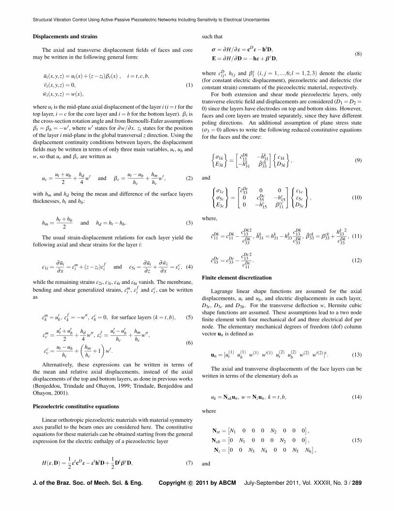
It is also worthwhile to analyse the effect of the relativedispersions of resistance and inductance values on the confidenceintervals of the responses of passive and active-passive controlledstructures and the control authority of the shunted piezoelectricactuators. Therefore, two additional values for relative dispersionsδR and δL were considered: 0.05 and 0.20. It is expected thathigher relative dispersions would lead to wider confidence intervalsand vice-versa. Figures 21, 22 and 23 show, respectively, thefrequency responses Gp, Gc and Gh of the structure with the extensionpiezoceramics for the two additional relative dispersions. It canbe observed in Figure 21, as expected, that the confidence intervalis widened (shrunk) compared to the previous case (Figure 15) forlarger (smaller) relative dispersions. The range of vibration amplitudereduction (considering the difference between peak responses)becomes 19-24 dB, for 5% relative dispersion, and 11-25 dB, for 20%relative dispersion. The same behaviour was observed for the controlauthority (Figure 22) and active-passive case (Figure 23). The range
103 103.5 104 104.5 105 105.5 106 106.5 1078
9
10
11
12
13
14
15
16
17
18
Mobili
ty (
m/s
/N, dB
)
Frequency (Hz) (a)
103 103.5 104 104.5 105 105.5 106 106.5 1078
9
10
11
12
13
14
15
16
17
18
Mobili
ty (
m/s
/N, dB
)
Frequency (Hz) (b)Figure 24. FRF of the beam with shear piezoceramic patch connected to apassive shunt circuit: GOC
p (dash-dot), GNp (solid), Gp (dashed) and GCI
p (filled)for: (a) δR = δL = 0.05 and (b) δR = δL = 0.20.
of vibration amplitude reduction when using the active-passive shuntcircuit remains 27-28 dB, for 5% relative dispersion, and is widenedto 24-29 dB, for 20% relative dispersion.
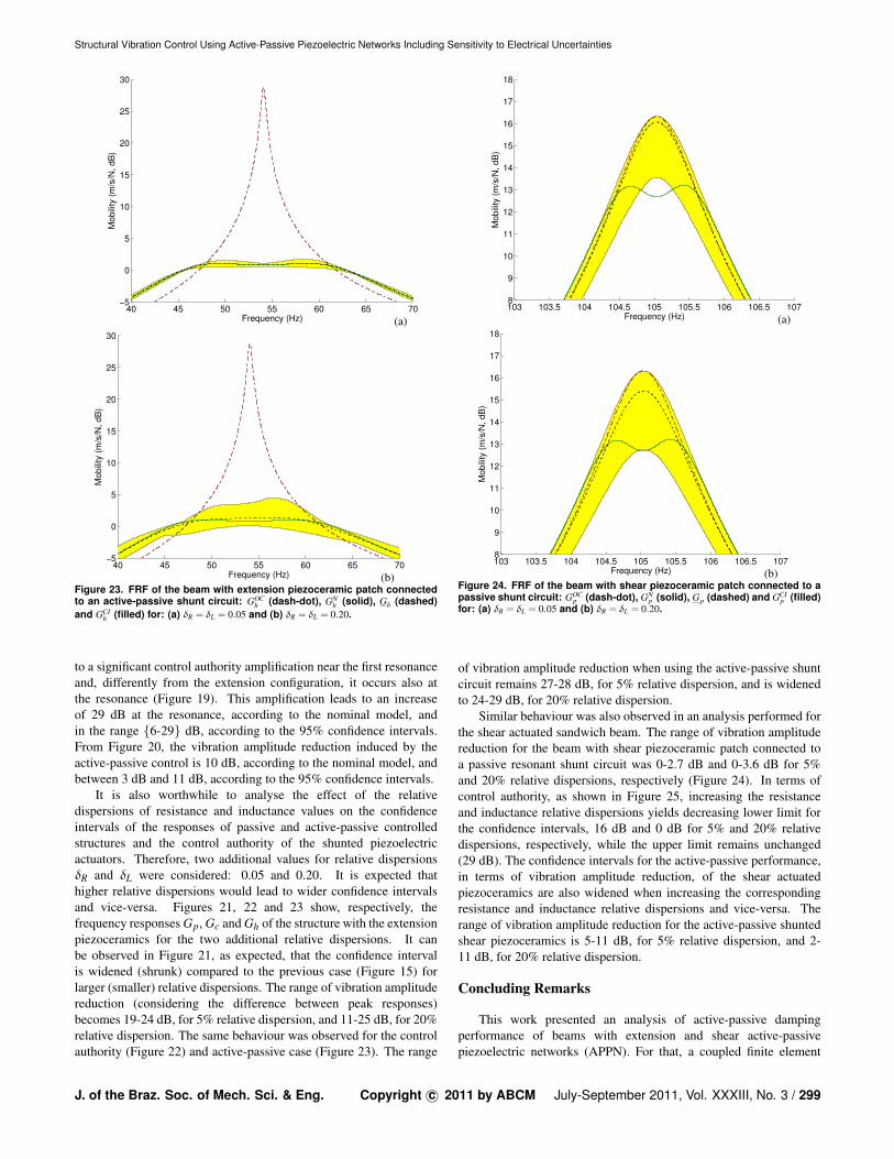
Similar behaviour was also observed in an analysis performed forthe shear actuated sandwich beam. The range of vibration amplitudereduction for the beam with shear piezoceramic patch connected toa passive resonant shunt circuit was 0-2.7 dB and 0-3.6 dB for 5%and 20% relative dispersions, respectively (Figure 24). In terms ofcontrol authority, as shown in Figure 25, increasing the resistanceand inductance relative dispersions yields decreasing lower limit forthe confidence intervals, 16 dB and 0 dB for 5% and 20% relativedispersions, respectively, while the upper limit remains unchanged(29 dB). The confidence intervals for the active-passive performance,in terms of vibration amplitude reduction, of the shear actuatedpiezoceramics are also widened when increasing the correspondingresistance and inductance relative dispersions and vice-versa. Therange of vibration amplitude reduction for the active-passive shuntedshear piezoceramics is 5-11 dB, for 5% relative dispersion, and 2-11 dB, for 20% relative dispersion.
Concluding Remarks
This work presented an analysis of active-passive dampingperformance of beams with extension and shear active-passivepiezoelectric networks (APPN). For that, a coupled finite element
J. of the Braz. Soc. of Mech. Sci. & Eng. Copyright c© 2011 by ABCM July-September 2011, Vol. XXXIII, No. 3 / 299

Heinsten F.L. dos Santos and Marcelo A. Trindade
90 95 100 105 110 115 120−100
−90
−80
−70
−60
−50
−40
−30
−20
Mo
bili
ty (
m/s
/V,
dB
)
Frequency (Hz) (a)
90 95 100 105 110 115 120−100
−90
−80
−70
−60
−50
−40
−30
−20
Mo
bili
ty (
m/s
/V,
dB
)
Frequency (Hz) (b)Figure 25. Control authority of the shear piezoceramic patch with andwithout shunt circuit: GV
c (dash-dot), GNc (solid), Gc (dashed) and GCI
c (filled)for: (a) δR = δL = 0.05 and (b) δR = δL = 0.20.
model with mechanical and electrical degrees of freedom wasdeveloped and used to design passive and active control parameters.Then, a stochastic modeling and analysis of two cantilever beamconfigurations, with extension and shear APPN, was performed toevaluate the effect of uncertainties in circuit components on passiveand active-passive vibration control. Results have shown that active-passive shunt circuits can be very interesting since they may combinean adequate passive control performance with an increase of the activecontrol authority when a control voltage is applied to the circuit.For the extension configuration, vibration amplitude reductions ofup to 22 dB and 28 dB were obtained for the purely passive andactive-passive cases, respectively. Considering relative dispersions of10% for the resistance and inductance values, the passive and active-passive amplitude reductions were found to be in the ranges 16-24 dBand 27-28 dB, respectively. For the shear configuration, increases inthe active control authority of up to 29 dB due to a properly tunedresonant circuit were observed. When subjected to uncertainties inthe resistance and inductance values, with 10% relative dispersions,the control authority increase was found to be in the range of 6-29 dB.
Acknowledgements
This research was supported by FAPESP and CNPq, throughresearch grants 04/10255-7 and 473105/2004-7, which the authorsgratefully acknowledge. The authors also acknowledge thesupport of the MCT/CNPq/FAPEMIG National Institute of Science
100 102 104 106 108 1100
2
4
6
8
10
12
14
16
18
20
Mobili
ty (
m/s
/N, dB
)
Frequency (Hz) (a)
100 102 104 106 108 1100
2
4
6
8
10
12
14
16
18
20
Mobili
ty (
m/s
/N, dB
)
Frequency (Hz) (b)Figure 26. FRF of the beam with shear piezoceramic patch connected to anactive-passive shunt circuit: GOC
h (dash-dot), GNh (solid), Gh (dashed) and GCI
h(filled) for: (a) δR = δL = 0.05 and (b) δR = δL = 0.20.
and Technology on Smart Structures in Engineering, grantno.574001/2008-5.
References
Andreaus, U. and Porfiri, M., 2007, “Effect of electrical uncertainties onresonant piezoelectric shunting,” Journal of Intelligent Material Systems andStructures, Vol. 18, pp. 477-485.
Baillargeon, B.P. and Vel, S.S., 2005, “Active vibration suppressionof sandwich beams using piezoelectric shear actuators: experiments andnumerical simulations,” Journal of Intelligent Materials Systems andStructures, Vol. 16, No. 6, pp. 517–530.
Benjeddou, A., 2007, “Shear-mode piezoceramic advanced materials andstructures: a state of the art,” Mechanics of Advanced Materials and Structures,Vol. 14, No. 4, pp. 263-275.
Benjeddou, A. and Ranger-Vieillard, J.-A., 2004, “Passive vibrationdamping using shunted shear-mode piezoceramics,” In Topping, B.H.V.and Mota Soares, C.A., eds., Proceedings of the Seventh InternationalConference on Computational Structures Technology, Civil-Comp Press,Stirling, Scotland, p. 4.
Benjeddou, A., Trindade, M.A., and Ohayon, R., 1999, “New shearactuated smart structure beam finite element,” AIAA Journal, Vol. 37, No.3, pp. 378-383.
Cataldo, E., Soize, C., Sampaio, R. and Desceliers, C., 2009,“Probabilistics modeling of a nonlinear dynamical system used for producingvoice,” Computational Mechanics, Vol. 43, pp. 265-275
Forward, R., 1979, “Electronic damping of vibrations in opticalstructures,” Applied Optics, Vol. 18, No. 5, pp. 690-697.
Hagood, N.W. and von Flotow, A., 1991, “Damping of structuralvibrations with piezoelectric materials and passive electrical networks,”
300 / Vol. XXXIII, No. 3, July-September 2011 ABCM

Structural Vibration Control Using Active-Passive Piezoelectric Networks Including Sensitivity to Electrical Uncertainties
Journal of Sound and Vibration, Vol. 146, No. 2, pp. 243-268.Raja, S., Prathap, G., and Sinha, P.K., 2002, “Active vibration control
of composite sandwich beams with piezoelectric extension-bending and shearactuators,” Smart Materials and Structures, Vol. 11, No. 1, pp. 63-71.
Ritto, T., Soize, C., Sampaio, R., 2010, “Stochastic dynamics of a drill-string with uncertain weight-on-hook,” Journal of the Brazilian Society ofMechanical Sciences and Engineering, Vol. 32, No. 3, pp. 250-258.
Soize, C., 2001, “Maximum entropy approach for modeling randomuncertainties in transient elastodynamics,” Journal of the Acoustical Societyof America, Vol. 109, No. 5, pp. 1979-1996.
Sun, C.T. and Zhang, X.D., 1995, “Use of thickness-shear mode inadaptive sandwich structures,” Smart Materials and Structures, Vol. 4, No.3, pp. 202-206.
Thornburgh, R.P., and Chattopadhyay, A., 2003, “Modeling andoptimization of passively damped adaptive composite structures,” Journal ofIntelligent Materials Systems and Structures, Vol. 14, No. 4-5, pp. 247-256.
Trindade, M.A. and Benjeddou, A., 2006, “On higher-order modelling ofsmart beams with embedded shear-mode piezoceramic actuators and sensors,”Mechanics of Advanced Materials and Structures, Vol. 13, No. 5, pp. 357-369.
Trindade, M.A. and Benjeddou, A., 2009, “Effective electromechanicalcoupling coefficients of piezoelectric adaptive structures: critical evaluationand optimization,” Mechanics of Advanced Materials and Structures, Vol. 16,No. 3, pp. 210-223.
Trindade, M.A., Benjeddou, A., and Ohayon, R., 1999, “Parametricanalysis of the vibration control of sandwich beams through shear-basedpiezoelectric actuation,” Journal of Intelligent Materials Systems andStructures, Vol. 10, No. 5, pp. 377-385.
Trindade, M.A., Benjeddou, A., and Ohayon, R., 2001, “Finiteelement modeling of hybrid active-passive vibration damping of multilayerpiezoelectric sandwich beams – part 2: System analysis,” InternationalJournal for Numerical Methods in Engineering, Vol. 51, No. 7, pp. 855-864.
Trindade, M.A. and Maio, C.E.B., 2008, “Multimodal passive vibrationcontrol of sandwich beams with shunted shear piezoelectric materials,” SmartMaterials and Structures, Vol. 17, art. no. 055015.
Tsai, M.S., and Wang, K.W., 1999, “On the structural dampingcharacteristics of active piezoelectric actuators with passive shunt,” Journalof Sound and Vibration, Vol. 221, No.1, pp. 1-22.
Viana, F.A.C. and Steffen Jr., V., 2006, “Multimodal vibration dampingthrough piezoelectric patches and optimal resonant shunt circuits,” Journal ofthe Brazilian Society of Mechanical Sciences and Engineering, Vol. 28, No.3, pp. 293-310.
J. of the Braz. Soc. of Mech. Sci. & Eng. Copyright c© 2011 by ABCM July-September 2011, Vol. XXXIII, No. 3 / 301