structural steel properties & design charts book · the structural steel properties and design...
TRANSCRIPT
March 2016
Structural Steel Properties & Design Charts Book

The Easysteel Way
Our Values
We all have to contribute to ensure success - It’s “The Easysteel Way”
Safety - “Because we want to,not because we have to”We want zero harm for our work mates, colleagues, customersand suppliers - ensuring that our actions or inactions never put aperson’s health or safety at risk.
Steel is our businessWe are passionate about steel and its benefits and take pride in each person making a positive difference to our customers and suppliers.
Achieve big results throughdaily actionsWe are empowered to make decisions because we thrive onsuccess and winning.
Great place to work...Great people to deal withWork is FUN, REWARDING and CHALLENGINGbecause of the colleagues, customers and supplierswe work with.
Customer success is our successWe will ensure that our customers see us as their steel merchant of choice and thereby ensure that their success is also ours.
One team... One resultWe believe results are the true measure of our success.We work for outstanding results for our shareholders, our customers and for each other
3
Introduction
Fletcher Easysteel is a division of Fletcher Building Limited. The company prides itself on its position as a leading steel distributor in New Zealand providing a comprehensive range of products and services to meet the needs of this market.
The Structural Steel Properties and Design Charts Catalogue is a directory of products and services available from Fletcher Easysteel and is provided as a guide to assist customers when determining their requirements.
It is by no means an exhaustive list of the company’s service portfolio. For in this dynamic environment, operating within a more prevalent global economy, the range of products and services that Fletcher Easysteel offers is ever changing.
The Structural Steel Properties and Design Charts Catalogue is an indication of the company’s commitment to informing customers of what is available from your steel supplier. Supplementary product catalogues are;
• The Special Steels Book • Pipe and Pipe Fittings Catalogue • The Steel Book
Every care has been taken by staff in producing this catalogue. Fletcher Easysteel has endeavoured to ensure accuracy of the information contained herein, however Fletcher Easysteel cannot and does not accept responsibility for any loss or damage sustained by any party through use of this information.
Quality Fletcher Easysteel continues to maintain a strong commitment to the principles which have become total quality management. This results in minimum waste, improved efficiencies and a service promise which meets customer requirements. Fletcher Easysteel has a philosophy of continuous improvement in all areas of its business.
Technical Advice Fletcher Easysteel provides technical expertise on all products and services it markets. Specialist advice is available on product properties, product selection and specific end use application. Any advice given should subsequently be authorised by a qualified engineer.
Information Systems Fletcher Easysteel operates an ERP system across its business. This includes handling front-line customer enquiries and orders, to back-office automatic stock replenishment in line with customer forecasts.
Supporting this is a forecasting system which captures historic sales information, combining it with future market intelligence to provide the best possible forecast. This enables us to have the right product on hand at the right time to meet customer requirements and to ensure excellent service for our customers.
Fletcher Easysteel is continually researching the new opportunities information technology offers in making business easier with customers and suppliers alike.
Suppliers Fletcher Easysteel has a centrally based supply chain which leverages its strong relationship with suppliers to provide highly competitive offers to its customers. These offers are sourced globally from quality steel mills and suppliers which enables its customers to compete in both domestic and export markets.
Health & Safety At Fletcher Easysteel, our safety goal is zero harm. Health and Safety is our highest priority, not only for all employees, but also for our customers, suppliers, contractors and visitors. We take a pro-active approach in regards to Health & Safety and Environment, and we are continually developing and implementing systems to ensure our workplace is a safe one. At Fletcher Easysteel, everyone is responsible for ensuring that we are working in a safe manner -
Because we want to... not because we have to!
Introduction
Introduction 1
Universal & Taper Flange Beams 3 Dimensions and Properties 4 Properties for Fire and Section Capacities - to NZS 3404 5 Design Load Capacities for Members with Lateral Restraint - Subjuect to bending about X-axis Grade 250 6 Grade 300 8 Grade 350 10 Design Moment Capacities for Members without Lateral Restraint (am=1.0) - Subjuect to bending about X-axis Grade 250 12 Grade 300 13 Grade 350 14 Design Load Capacities for Members Subject to Axial Compression Buckling about Y-axis Grade 250 15 Grade 300 16 Grade 350 17
Universal Columns 18 Dimensions and Properties 19 Properties for Fire and Section Capacities - to NZS 3404 20 Design Load Capacities for Members with Lateral Restraint - Subjuect to bending about X-axis Grade 250 21 Grade 300 21 Grade 350 22 Design Moment Capacities for Members without Lateral Restraint - Subjuect to bending about X-axis Grade 250 23 Grade 300 23 Grade 350 24
Standard Welded Columns & Beams 25 Standard Welded Columns - Dimensions and Properties 26 Standard Welded Beams - Dimensions and Properties 27
4
Parallel & Taper Flange Channels 29 Dimensions and Properties 30 Properties for Fire and Section Capacities - to NZS 3404 31 Design Load Capacities for Members with Full Lateral Restraint - Subjuect to bending about X-axis Grade 250 32 Grade 300 33 Grade 350 34
Hollow Sections 35 Circular Hollows - Dimensions, Section Properties and Properties for assesing Section Capacities - to NZS 3404 36 Design Load Capacities for Members Subject to Axial Compression Buckling about Y-axis Grade B or API 5L Grade B 37 Square Hollows - Dimensions and Properties Grade 350 38 Grade 450 39 Design Load Capacities for Members Subject to Axial Compression Buckling about Y-axis Grade 350 40 Grade 450 41 Rectangular Hollows - Dimensions and Properties Grade 350 42 Grade 450 43 Design Load Capacities for Members Subject to Axial Compression Buckling about Y-axis Grade 350 44 Grade 450 45
Service Centres 46 Processing 47 Indent Services 48
Universal & Taper Flange Beams
5
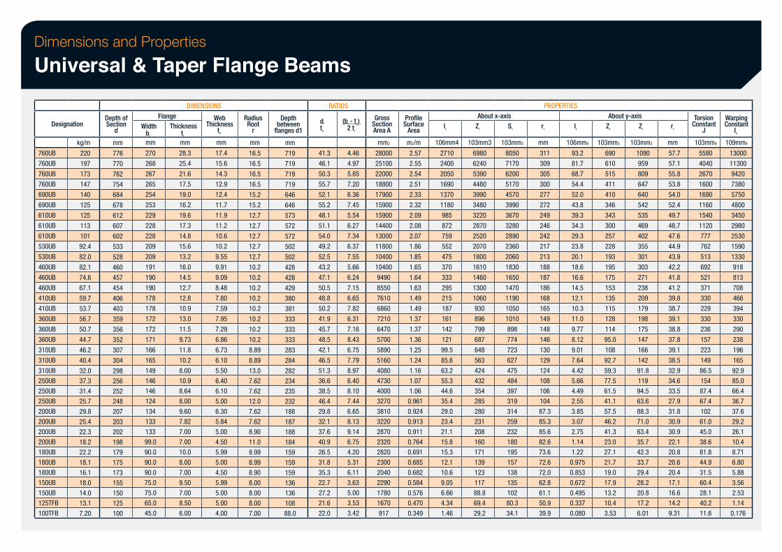
Dimensions and Properties
Universal & Taper Flange Beams
Designation
760UB
760UB
760UB
760UB
690UB
690UB
610UB
610UB
610UB
530UB
530UB
460UB
460UB
460UB
410UB
410UB
360UB
360UB
360UB
310UB
310UB
310UB
250UB
250UB
250UB
200UB
200UB
200UB
200UB
180UB
180UB
180UB
150UB
150UB
125TFB
100TFB
kg/m
220
197
173
147
140
125
125
113
101
92.4
82.0
82.1
74.6
67.1
59.7
53.7
56.7
50.7
44.7
46.2
40.4
32.0
37.3
31.4
25.7
29.8
25.4
22.3
18.2
22.2
18.1
16.1
18.0
14.0
13.1
7.20
Depth of Section
d
mm
776
770
762
754
684
678
612
607
602
533
528
460
457
454
406
403
359
356
352
307
304
298
256
252
248
207
203
202
198
179
175
173
155
150
125
100
Flange Width
bf
mm
270
268
267
265
254
253
229
228
228
209
209
191
190
190
178
178
172
172
171
166
165
149
146
146
124
134
133
133
99.0
90.0
90.0
90.0
75.0
75.0
65.0
45.0
DIMENSIONS
Thickness tf
mm
28.3
25.4
21.6
17.5
19.0
16.2
19.6
17.3
14.8
15.6
13.2
16.0
14.5
12.7
12.8
10.9
13.0
11.5
9.73
11.8
10.2
8.00
10.9
8.64
8.00
9.60
7.82
7.00
7.00
10.0
8.00
7.00
9.50
7.00
8.50
6.00
Thickness Web
tw
mm
17.4
15.6
14.3
12.9
12.4
11.7
11.9
11.2
10.6
10.2
9.55
9.91
9.09
8.48
7.80
7.59
7.95
7.29
6.86
6.73
6.10
5.50
6.40
6.10
5.00
6.30
5.84
5.00
4.50
5.99
5.00
4.50
5.99
5.00
5.00
4.00
Radius Root
r
mm
16.5
16.5
16.5
16.5
15.2
15.2
12.7
12.7
12.7
12.7
12.7
10.2
10.2
10.2
10.2
10.2
10.2
10.2
10.2
8.89
8.89
13.0
7.62
7.62
12.0
7.62
7.62
8.90
11.0
8.99
8.99
8.90
8.00
8.00
8.00
7.00
flanges d1 between
Depth
mm
719
719
719
719
646
646
573
572
572
502
502
428
428
429
380
381
333
333
333
283
284
282
234
235
232
188
187
188
184
159
159
159
136
136
108
88.0
RATIOS
d1
tw
41.3
46.1
50.3
55.7
52.1
55.2
48.1
51.1
54.0
49.2
52.5
43.2
47.1
50.5
48.8
50.2
41.9
45.7
48.5
42.1
46.5
51.3
36.6
38.5
46.4
29.8
32.1
37.6
40.9
26.5
31.8
35.3
22.7
27.2
21.6
22.0
(bf - tw) 2 tf
4.46
4.97
5.85
7.20
6.36
7.45
5.54
6.27
7.34
6.37
7.55
5.66
6.24
7.15
6.65
7.82
6.31
7.16
8.43
6.75
7.79
8.97
6.40
8.10
7.44
6.65
8.13
9.14
6.75
4.20
5.31
6.11
3.63
5.00
3.53
3.42
Section Gross
Area A
mm2
28000
25100
22000
18800
17900
15900
15900
14400
13000
11800
10400
10400
9490
8550
7610
6860
7210
6470
5700
5890
5160
4080
4730
4000
3270
3810
3220
2870
2320
2820
2300
2040
2290
1780
1670
917
Surface Profile
Area
m2/m
2.57
2.55
2.54
2.51
2.33
2.32
2.09
2.08
2.07
1.86
1.85
1.65
1.64
1.63
1.49
1.49
1.37
1.37
1.36
1.25
1.24
1.16
1.07
1.06
0.961
0.924
0.913
0.911
0.764
0.691
0.685
0.682
0.584
0.576
0.470
0.349
Ix
106mm4
2710
2400
2050
1690
1370
1180
985
872
759
552
475
370
333
295
215
187
161
142
121
99.5
85.6
63.2
55.3
44.6
35.4
29.0
23.4
21.1
15.8
15.3
12.1
10.6
9.05
6.66
4.34
1.46
About x-axis Zx
103mm3
6980
6240
5390
4480
3990
3480
3220
2870
2520
2070
1800
1610
1460
1300
1060
930
896
799
687
648
563
424
432
354
285
280
231
208
160
171
139
123
117
88.8
69.4
29.2
Sx
103mm3
8050
7170
6200
5170
4570
3990
3670
3280
2890
2360
2060
1830
1650
1470
1190
1050
1010
898
774
723
627
475
484
397
319
314
259
232
180
195
157
138
135
102
80.3
34.1
PROPERTIES
rx
mm
311
309
305
300
277
272
249
246
242
217
213
188
187
186
168
165
149
148
146
130
129
124
108
106
104
87.3
85.3
85.6
82.6
73.6
72.6
72.0
62.8
61.1
50.9
39.9
Iy
106mm4
93.2
81.7
68.7
54.4
52.0
43.8
39.3
34.3
29.3
23.8
20.1
18.6
16.6
14.5
12.1
10.3
11.0
9.77
8.12
9.01
7.64
4.42
5.66
4.49
2.55
3.85
3.07
2.75
1.14
1.22
0.975
0.853
0.672
0.495
0.337
0.080
About y-axis Zy
103mm3
690
610
515
411
410
346
343
300
257
228
193
195
175
153
135
115
128
114
95.0
108
92.7
59.3
77.5
61.5
41.1
57.5
46.2
41.3
23.0
27.1
21.7
19.0
17.9
13.2
10.4
3.53
Zy
103mm3
1090
959
809
647
640
542
535
469
402
355
301
303
271
238
209
179
198
175
147
166
142
91.8
119
94.5
63.6
88.3
71.0
63.4
35.7
42.3
33.7
29.4
28.2
20.8
17.2
6.01
ry
mm
57.7
57.1
55.8
53.8
54.0
52.4
49.7
48.7
47.6
44.9
43.9
42.2
41.8
41.2
39.8
38.7
39.1
38.8
37.8
39.1
38.5
32.9
34.6
33.5
27.9
31.8
30.9
30.9
22.1
20.8
20.6
20.4
17.1
16.6
14.2
9.31
Constant Torsion
J
103mm4
5580
4040
2670
1600
1690
1160
1540
1120
777
762
513
692
521
371
330
229
330
236
157
223
149
86.5
154
87.4
67.4
102
61.0
45.0
38.6
81.8
44.9
31.5
60.4
28.1
40.2
11.6
Constant Warping
Iw
109mm6
13000
11300
9420
7380
5750
4800
3450
2980
2530
1590
1330
918
813
708
466
394
330
290
238
196
165
92.9
85.0
66.4
36.7
37.6
29.2
26.1
10.4
8.71
6.80
5.88
3.56
2.53
1.14
0.176
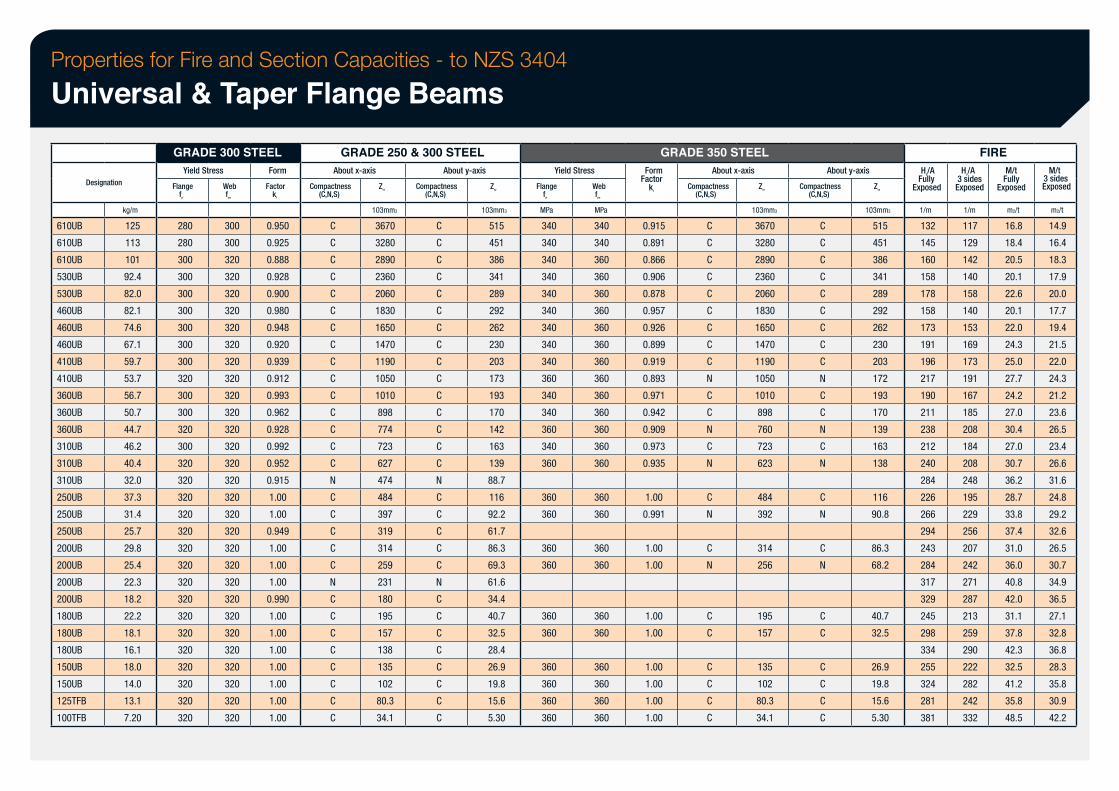
Properties for Fire and Section Capacities - to NZS 3404
Universal & Taper Flange Beams
Designation
610UB
610UB
610UB
530UB
530UB
460UB
460UB
460UB
410UB
410UB
360UB
360UB
360UB
310UB
310UB
310UB
250UB
250UB
250UB
200UB
200UB
200UB
200UB
180UB
180UB
180UB
150UB
150UB
125TFB
100TFB
kg/m
125
113
101
92.4
82.0
82.1
74.6
67.1
59.7
53.7
56.7
50.7
44.7
46.2
40.4
32.0
37.3
31.4
25.7
29.8
25.4
22.3
18.2
22.2
18.1
16.1
18.0
14.0
13.1
7.20
GRADE 300 STEEL Yield Stress
Flange fyf
280
280
300
300
300
300
300
300
300
320
300
300
320
300
320
320
320
320
320
320
320
320
320
320
320
320
320
320
320
320
Web fyw
300
300
320
320
320
320
320
320
320
320
320
320
320
320
320
320
320
320
320
320
320
320
320
320
320
320
320
320
320
320
Form
Factor kf
0.950
0.925
0.888
0.928
0.900
0.980
0.948
0.920
0.939
0.912
0.993
0.962
0.928
0.992
0.952
0.915
1.00
1.00
0.949
1.00
1.00
1.00
0.990
1.00
1.00
1.00
1.00
1.00
1.00
1.00
GRADE 250 & 300 STEEL About x-axis
Compactness (C,N,S)
C
C
C
C
C
C
C
C
C
C
C
C
C
C
C
N
C
C
C
C
C
N
C
C
C
C
C
C
C
C
Zex
103mm3
3670
3280
2890
2360
2060
1830
1650
1470
1190
1050
1010
898
774
723
627
474
484
397
319
314
259
231
180
195
157
138
135
102
80.3
34.1
About y-axis
Compactness (C,N,S)
C
C
C
C
C
C
C
C
C
C
C
C
C
C
C
N
C
C
C
C
C
N
C
C
C
C
C
C
C
C
Zey
103mm3
515
451
386
341
289
292
262
230
203
173
193
170
142
163
139
88.7
116
92.2
61.7
86.3
69.3
61.6
34.4
40.7
32.5
28.4
26.9
19.8
15.6
5.30
Yield Stress
Flange fyf
MPa
340
340
340
340
340
340
340
340
340
360
340
340
360
340
360
360
360
360
360
360
360
360
360
360
360
Web fyw
MPa
340
340
360
360
360
360
360
360
360
360
360
360
360
360
360
360
360
360
360
360
360
360
360
360
360
GRADE 350 STEEL
Factor Form
kf
0.915
0.891
0.866
0.906
0.878
0.957
0.926
0.899
0.919
0.893
0.971
0.942
0.909
0.973
0.935
1.00
0.991
1.00
1.00
1.00
1.00
1.00
1.00
1.00
1.00
About x-axis
Compactness (C,N,S)
C
C
C
C
C
C
C
C
C
N
C
C
N
C
N
C
N
C
N
C
C
C
C
C
C
Zex
103mm3
3670
3280
2890
2360
2060
1830
1650
1470
1190
1050
1010
898
760
723
623
484
392
314
256
195
157
135
102
80.3
34.1
About y-axis
Compactness (C,N,S)
C
C
C
C
C
C
C
C
C
N
C
C
N
C
N
C
N
C
N
C
C
C
C
C
C
Zey
103mm3
515
451
386
341
289
292
262
230
203
172
193
170
139
163
138
116
90.8
86.3
68.2
40.7
32.5
26.9
19.8
15.6
5.30
Exposed Fully Hp/A
1/m
132
145
160
158
178
158
173
191
196
217
190
211
238
212
240
284
226
266
294
243
284
317
329
245
298
334
255
324
281
381
FIRE
Exposed 3 sides Hp/A
1/m
117
129
142
140
158
140
153
169
173
191
167
185
208
184
208
248
195
229
256
207
242
271
287
213
259
290
222
282
242
332
Exposed Fully M/t
m2/t
16.8
18.4
20.5
20.1
22.6
20.1
22.0
24.3
25.0
27.7
24.2
27.0
30.4
27.0
30.7
36.2
28.7
33.8
37.4
31.0
36.0
40.8
42.0
31.1
37.8
42.3
32.5
41.2
35.8
48.5
M/t 3 sides Exposed
m2/t
14.9
16.4
18.3
17.9
20.0
17.7
19.4
21.5
22.0
24.3
21.2
23.6
26.5
23.4
26.6
31.6
24.8
29.2
32.6
26.5
30.7
34.9
36.5
27.1
32.8
36.8
28.3
35.8
30.9
42.2
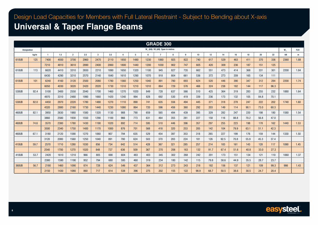
Design Load Capacities for Members with Full Lateral Restraint - Subject to Bending about X-axis
Universal & Taper Flange Beams
8
Designation
610UB
610UB
610UB
530UB
530UB
460UB
460UB
460UB
410UB
410UB
360UB
kg/m
125
113
101
92.4
82.0
82.1
74.6
67.1
59.7
53.7
56.7
1
7400
7210
6620
6430
6240
6050
5100
4970
4450
4320
3950
3860
3570
3500
3180
3120
2570
2540
2420
2380
2180
2150
1.5
4930
4810
4410
4290
4160
4030
3400
3310
2970
2880
2630
2580
2380
2340
2120
2080
1710
1700
1610
1590
1460
1430
2
3700
3610
3310
3210
3120
3020
2550
2480
2220
2160
1980
1930
1780
1750
1590
1560
1280
1270
1210
1190
1090
1080
2.5
2960
2890
2650
2570
2500
2420
2040
1990
1780
1730
1580
1550
1430
1400
1270
1250
1030
1020
966
952
874
860
3
2470
2400
2210
2140
2080
2020
1700
1660
1480
1440
1320
1290
1190
1170
1060
1040
856
848
805
794
728
717
3.5
2110
2060
1890
1840
1780
1730
1460
1420
1270
1230
1130
1100
1020
1000
907
891
734
727
690
680
624
614
4
1850
1800
1650
1610
1560
1510
1270
1240
1110
1080
988
966
892
876
794
780
642
636
604
595
546
538
5
1480
1440
1320
1290
1250
1210
1020
994
890
864
790
773
714
701
635
624
514
509
483
460
437
396
GRADE 300 WLC1 (kN) / Ws (kN) Span in metres
6
1230
1200
1100
1070
1040
1010
849
828
741
720
659
631
595
568
529
503
428
367
403
319
364
275
7
1060
1030
945
918
891
864
728
692
635
596
565
464
510
418
454
370
367
270
345
234
312
202
8
925
902
827
804
780
729
637
530
556
456
494
355
446
320
397
283
321
206
302
180
273
155
9
822
747
735
661
693
576
566
419
494
360
439
281
396
253
353
224
285
163
268
142
243
122
10
740
605
662
536
624
466
510
339
445
292
395
227
357
205
318
181
257
132
242
115
218
98.9
12
617
420
551
372
520
324
425
236
371
203
329
158
297
142
265
126
214
91.7
201
79.8
182
68.7
14
529
309
473
273
446
238
364
173
318
149
282
116
255
104
227
92.5
183
67.4
173
58.6
156
50.5
16
463
236
414
209
390
182
319
132
278
114
247
88.8
223
79.9
199
70.8
161
51.6
151
44.9
137
38.6
18
411
187
368
165
347
144
283
105
247
90.1
220
70.2
198
63.1
176
55.9
143
40.8
134
35.5
121
30.5
20
370
151
331
134
312
117
255
84.8
222
73.0
198
56.8
178
51.1
159
45.3
128
33.0
121
28.7
109
24.7
22
336
125
301
111
284
96.3
232
70.1
202
60.3
180
47.0
162
42.3
144
37.4
117
27.3
110
23.7
99.3
20.4
WLC2
kN
2360
2200
2200
1880
1740
1580
1440
1330
1090
1060
986
FLR
m
1.88
1.84
1.74
1.64
1.60
1.54
1.53
1.50
1.45
1.37
1.43
9
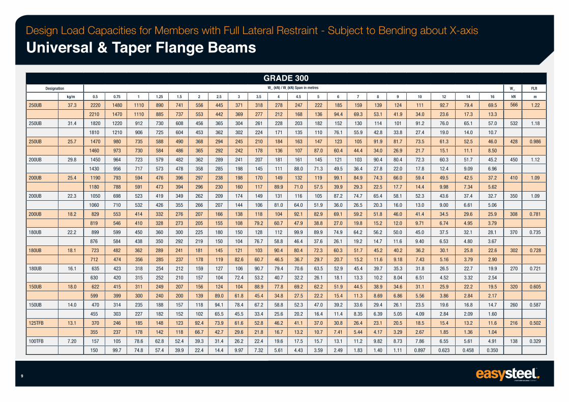
Design Load Capacities for Members with Full Lateral Restraint - Subject to Bending about X-axis
Universal & Taper Flange Beams
250UB
250UB
250UB
200UB
200UB
200UB
200UB
180UB
180UB
180UB
150UB
150UB
Designation
125TFB
100TFB
kg/m
37.3
31.4
25.7
29.8
25.4
22.3
18.2
22.2
18.1
16.1
18.0
14.0
13.1
7.20
0.5
2220
2210
1820
1810
1470
1460
1450
1430
1190
1180
1050
1060
829
819
899
876
723
712
635
630
622
599
470
455
370
355
157
150
0.75
1480
1470
1220
1210
980
973
964
956
793
788
698
710
553
546
599
584
482
474
423
420
415
399
314
303
246
237
105
99.7
1
1110
1110
912
906
735
730
723
717
594
591
523
532
414
410
450
438
362
356
318
315
311
300
235
227
185
178
78.6
74.8
1.25
890
885
730
725
588
584
579
573
476
473
419
426
332
328
360
350
289
285
254
252
249
240
188
182
148
142
62.8
57.4
1.5
741
737
608
604
490
486
482
478
396
394
349
355
276
273
300
292
241
237
212
210
207
200
157
152
123
118
52.4
39.9
2
556
553
456
453
368
365
362
358
297
296
262
266
207
205
225
219
181
178
159
157
156
139
118
102
92.4
66.7
39.3
22.4
2.5
445
442
365
362
294
292
289
285
238
230
209
207
166
155
180
150
145
119
127
104
124
89.0
94.1
65.5
73.9
42.7
31.4
14.4
3
371
369
304
302
245
242
241
198
198
160
174
144
138
108
150
104
121
82.6
106
72.4
104
61.8
78.4
45.5
61.6
29.6
26.2
9.97
GRADE 300 WLC1 (kN) / Ws (kN) Span in metres
3.5
318
277
261
224
210
178
207
145
170
117
149
106
118
79.2
128
76.7
103
60.7
90.7
53.2
88.9
45.4
67.2
33.4
52.8
21.8
22.4
7.32
4
278
212
228
171
184
136
181
111
149
89.9
131
81.0
104
60.7
112
58.8
90.4
46.5
79.4
40.7
77.8
34.8
58.8
25.6
46.2
16.7
19.6
5.61
4.5
247
168
203
135
163
107
161
88.0
132
71.0
116
64.0
92.1
47.9
99.9
46.4
80.4
36.7
70.6
32.2
69.2
27.5
52.3
20.2
41.1
13.2
17.5
4.43
5
222
136
182
110
147
87.0
145
71.3
119
57.5
105
51.9
82.9
38.8
89.9
37.6
72.3
29.7
63.5
26.1
62.2
22.2
47.0
16.4
37.0
10.7
15.7
3.59
6
185
94.4
152
76.1
123
60.4
121
49.5
99.1
39.9
87.2
36.0
69.1
27.0
74.9
26.1
60.3
20.7
52.9
18.1
51.9
15.4
39.2
11.4
30.8
7.41
13.1
2.49
7
159
69.3
130
55.9
105
44.4
103
36.4
84.9
29.3
74.7
26.5
59.2
19.8
64.2
19.2
51.7
15.2
45.4
13.3
44.5
11.3
33.6
8.35
26.4
5.44
11.2
1.83
8
139
53.1
114
42.8
91.9
34.0
90.4
27.8
74.3
22.5
65.4
20.3
51.8
15.2
56.2
14.7
45.2
11.6
39.7
10.2
38.9
8.69
29.4
6.39
23.1
4.17
9.82
1.40
9
124
41.9
101
33.8
81.7
26.9
80.4
22.0
66.0
17.7
58.1
16.0
46.0
12.0
50.0
11.6
40.2
9.18
35.3
8.04
34.6
6.86
26.1
5.05
20.5
3.29
8.73
1.11
10
111
34.0
91.2
27.4
73.5
21.7
72.3
17.8
59.4
14.4
52.3
13.0
41.4
9.71
45.0
9.40
36.2
7.43
31.8
6.51
31.1
5.56
23.5
4.09
18.5
2.67
7.86
0.897
12
92.7
23.6
76.0
19.0
61.3
15.1
60.3
12.4
49.5
9.98
43.6
9.00
34.5
6.74
37.5
6.53
30.1
5.16
26.5
4.52
25.9
3.86
19.6
2.84
15.4
1.85
6.55
0.623
14
79.4
17.3
65.1
14.0
52.5
11.1
51.7
9.09
42.5
7.34
37.4
6.61
29.6
4.95
32.1
4.80
25.8
3.79
22.7
3.32
22.2
2.84
16.8
2.09
13.2
1.36
5.61
0.458
16
69.5
13.3
57.0
10.7
46.0
8.50
45.2
6.96
37.2
5.62
32.7
5.06
25.9
3.79
28.1
3.67
22.6
2.90
19.9
2.54
19.5
2.17
14.7
1.60
11.6
1.04
4.91
0.350
WLC2
kN
566
532
428
450
410
350
308
370
302
270
320
260
216
138
FLR
m
1.22
1.18
0.986
1.12
1.09
1.09
0.781
0.735
0.728
0.721
0.605
0.587
0.502
0.329
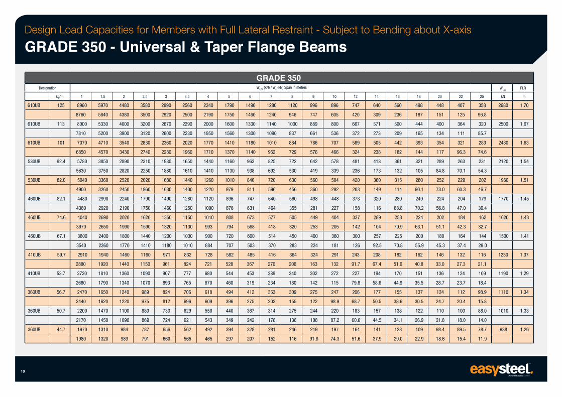
Design Load Capacities for Members with Full Lateral Restraint - Subject to Bending about X-axis
GRADE 350 - Universal & Taper Flange Beams
Designation
610UB
610UB
610UB
530UB
530UB
460UB
460UB
460UB
410UB
410UB
360UB
360UB
360UB
10
kg/m
125
113
101
92.4
82.0
82.1
74.6
67.1
59.7
53.7
56.7
50.7
44.7
1
8960
8760
8000
7810
7070
6850
5780
5630
5040
4900
4480
4380
4040
3970
3600
3540
2910
2880
2720
2680
2470
2440
2200
2170
1970
1980
1.5
5970
5840
5330
5200
4710
4570
3850
3750
3360
3260
2990
2920
2690
2650
2400
2360
1940
1920
1810
1790
1650
1620
1470
1450
1310
1320
2
4480
4380
4000
3900
3540
3430
2890
2820
2520
2450
2240
2190
2020
1990
1800
1770
1460
1440
1360
1340
1240
1220
1100
1090
984
989
2.5
3580
3500
3200
3120
2830
2740
2310
2250
2020
1960
1790
1750
1620
1590
1440
1410
1160
1150
1090
1070
989
975
880
869
787
791
3
2990
2920
2670
2600
2360
2280
1930
1880
1680
1630
1490
1460
1350
1320
1200
1180
971
961
907
893
824
812
733
724
656
660
3.5
2560
2500
2290
2230
2020
1960
1650
1610
1440
1400
1280
1250
1150
1130
1030
1010
832
824
777
765
706
696
629
621
562
565
4
2240
2190
2000
1950
1770
1710
1440
1410
1260
1220
1120
1090
1010
993
900
884
728
721
680
670
618
609
550
543
492
465
5
1790
1750
1600
1560
1410
1370
1160
1130
1010
979
896
876
808
794
720
707
582
528
544
460
494
396
440
349
394
297
6
GRADE 350 WLC1 (kN) / Ws (kN) Span in metres
1490
1460
1330
1300
1180
1140
963
938
840
811
747
631
673
568
600
503
485
367
453
319
412
275
367
242
328
207
7
1280
1240
1140
1090
1010
952
825
692
720
596
640
464
577
418
514
370
416
270
389
234
353
202
314
178
281
152
8
1120
946
1000
837
884
729
722
530
630
456
560
355
505
320
450
283
364
206
340
180
309
155
275
136
246
116
9
996
747
889
661
786
576
642
419
560
360
498
281
449
253
400
224
324
163
302
142
275
122
244
108
219
91.8
10
896
605
800
536
707
466
578
339
504
292
448
227
404
205
360
181
291
132
272
115
247
98.9
220
87.2
197
74.3
12
747
420
667
372
589
324
481
236
420
203
373
158
337
142
300
126
243
91.7
227
79.8
206
68.7
183
60.6
164
51.6
14
640
309
571
273
505
238
413
173
360
149
320
116
289
104
257
92.5
208
67.4
194
58.6
177
50.5
157
44.5
141
37.9
16
560
236
500
209
442
182
361
132
315
114
280
88.8
253
79.9
225
70.8
182
51.6
170
44.9
155
38.6
138
34.1
123
29.0
18
498
187
444
165
393
144
321
105
280
90.1
249
70.2
224
63.1
200
55.9
162
40.8
151
35.5
137
30.5
122
26.9
109
22.9
20
448
151
400
134
354
117
289
84.8
252
73.0
224
56.8
202
51.1
180
45.3
146
33.0
136
28.7
124
24.7
110
21.8
98.4
18.6
22
407
125
364
111
321
96.3
263
70.1
229
60.3
204
47.0
184
42.3
164
37.4
132
27.3
124
23.7
112
20.4
100
18.0
89.5
15.4
25
358
96.8
320
85.7
283
74.6
231
54.3
202
46.7
179
36.4
162
32.7
144
29.0
116
21.1
109
18.4
98.9
15.8
88.0
14.0
78.7
11.9
WLC2
kN
2680
2500
2480
2120
1960
1770
1620
1500
1230
1190
1110
1010
938
FLR
m
1.70
1.67
1.63
1.54
1.51
1.45
1.43
1.41
1.37
1.29
1.34
1.33
1.26
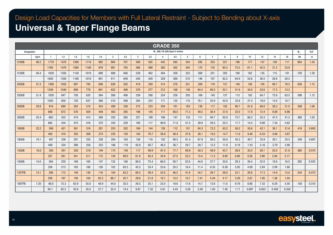
Design Load Capacities for Members with Full Lateral Restraint - Subject to Bending about X-axis
Universal & Taper Flange Beams
Designation
310UB
310UB
250UB
250UB
200UB
200UB
180UB
180UB
150UB
150UB
125TFB
100TFB
11
kg/m
46.2
40.4
37.3
31.4
29.8
25.4
22.2
18.1
18.0
14.0
13.1
7.20
1
1770
1760
1620
1620
1260
1240
1020
1020
816
806
663
665
506
492
407
400
350
337
264
256
208
200
88.0
84.1
1.2
1470
1470
1350
1350
1050
1040
847
850
680
672
553
554
421
410
339
334
291
281
220
213
173
167
73.3
62.3
1.4
1260
1260
1150
1160
897
889
726
728
583
576
474
475
361
352
291
286
250
241
189
183
149
136
62.9
45.8
1.6
1110
1100
1010
1010
785
778
635
637
510
504
415
416
316
308
255
250
219
211
165
160
130
104
55.0
35.0
1.8
982
979
898
901
698
691
564
566
453
448
368
370
281
274
226
222
194
172
147
126
116
82.3
48.9
27.7
2
884
881
808
811
628
622
508
510
408
403
332
333
253
235
204
186
175
139
132
102
104
66.7
44.0
22.4
2.5
707
705
646
649
502
498
406
408
326
285
265
230
202
150
163
119
140
89.0
106
65.5
83.2
42.7
35.2
14.4
3
589
588
539
540
419
378
339
304
272
198
221
160
169
104
136
82.6
117
61.8
88.0
45.5
69.3
29.6
29.3
9.97
GRADE 350 WLC1 (kN) / Ws (kN) Span in metres
3.5
505
499
462
429
359
277
290
224
233
145
189
117
144
76.7
116
60.7
99.9
45.4
75.4
33.4
59.4
21.8
25.1
7.32
4
442
382
404
329
314
212
254
171
204
111
166
89.9
126
58.8
102
46.5
87.4
34.8
66.0
25.6
52.0
16.7
22.0
5.61
4.5
393
302
359
260
279
168
226
135
181
88.0
147
71.0
112
46.4
90.5
36.7
77.7
27.5
58.7
20.2
46.2
13.2
19.6
4.43
5
354
245
323
210
251
136
203
110
163
71.3
133
57.5
101
37.6
81.4
29.7
69.9
22.2
52.8
16.4
41.6
10.7
17.6
3.59
6
295
170
269
146
209
94.4
169
76.1
136
49.5
111
39.9
84.3
26.1
67.9
20.7
58.3
15.4
44.0
11.4
34.7
7.41
14.7
2.49
7
253
125
231
107
179
69.3
145
55.9
117
36.4
94.7
29.3
72.2
19.2
58.2
15.2
49.9
11.3
37.7
8.35
29.7
5.44
12.6
1.83
8
221
95.5
202
82.2
157
53.1
127
42.8
102
27.8
82.9
22.5
63.2
14.7
50.9
11.6
43.7
8.69
33.0
6.39
26.0
4.17
11.0
1.40
9
196
75.5
180
64.9
140
41.9
113
33.8
90.7
22.0
73.7
17.7
56.2
11.6
45.2
9.18
38.8
6.86
29.3
5.05
23.1
3.29
9.78
1.11
10
177
61.1
162
52.6
126
34.0
102
27.4
81.6
17.8
66.3
14.4
50.6
9.40
40.7
7.43
35.0
5.56
26.4
4.09
20.8
2.67
8.80
0.897
12
147
42.5
135
36.5
105
23.6
84.7
19.0
68.0
12.4
55.3
9.98
42.1
6.53
33.9
5.16
29.1
3.86
22.0
2.84
17.3
1.85
7.33
0.623
14
126
31.2
115
26.8
89.7
17.3
72.6
14.0
58.3
9.09
47.4
7.34
36.1
4.80
29.1
3.79
25.0
2.84
18.9
2.09
14.9
1.36
6.29
0.458
16
111
23.9
101
20.5
78.5
13.3
63.5
10.7
51.0
6.96
41.5
5.62
31.6
3.67
25.5
2.90
21.9
2.17
16.5
1.60
13.0
1.04
5.50
0.350
WLC2
kN
804
720
638
598
508
460
416
340
360
292
244
156
FLR
m
1.34
1.28
1.15
1.12
1.06
1.03
0.693
0.687
0.570
0.553
0.473
0.310
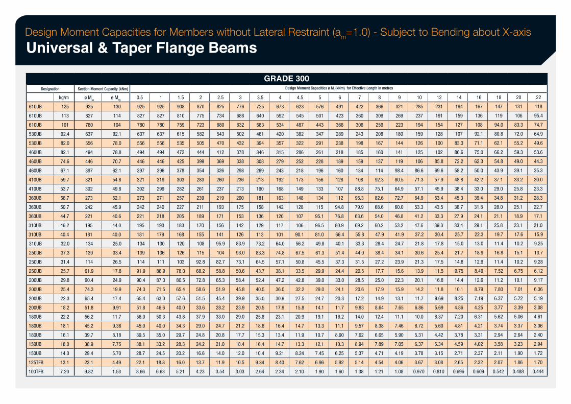
Design Moment Capacities for Members without Lateral Restraint (am=1.0) - Subject to Bending about X-axis
Universal & Taper Flange Beams
Designation
610UB
610UB
610UB
530UB
530UB
460UB
460UB
460UB
410UB
410UB
360UB
360UB
360UB
310UB
310UB
310UB
250UB
250UB
250UB
200UB
200UB
200UB
200UB
180UB
180UB
180UB
150UB
150UB
125TFB
100TFB
kg/m
125
113
101
92.4
82.0
82.1
74.6
67.1
59.7
53.7
56.7
50.7
44.7
46.2
40.4
32.0
37.3
31.4
25.7
29.8
25.4
22.3
18.2
22.2
18.1
16.1
18.0
14.0
13.1
7.20
Section Moment Capacity (kNm)
ø Msx
925
827
780
637
556
494
446
397
321
302
273
242
221
195
181
134
139
114
91.9
90.4
74.3
65.4
51.8
56.2
45.2
39.7
38.9
29.4
23.1
9.82
ø Msy
130
114
104
92.1
78.0
78.8
70.7
62.1
54.8
49.8
52.1
45.9
40.6
44.0
40.0
25.0
33.4
26.5
17.8
24.9
19.9
17.4
9.91
11.7
9.36
8.18
7.75
5.70
4.49
1.53
0.5
925
827
780
637
556
494
446
397
321
302
273
242
221
195
181
134
139
114
91.9
90.4
74.3
65.4
51.8
56.0
45.0
39.5
38.1
28.7
22.1
8.66
1
925
827
780
637
556
494
446
396
319
299
271
240
218
193
179
130
136
111
86.9
87.3
71.5
63.0
46.6
50.3
40.0
35.0
33.2
24.5
18.8
6.63
1.5
908
810
759
615
535
472
425
378
303
282
257
227
205
183
168
120
126
103
78.0
80.5
65.4
57.6
40.0
43.8
34.3
29.7
28.3
20.2
16.0
5.21
2
870
775
723
582
505
444
399
354
283
261
239
211
189
170
155
108
115
92.8
68.2
72.8
58.6
51.5
33.6
37.9
29.0
24.8
24.2
16.6
13.7
4.23
2.5
825
734
680
543
470
412
369
326
260
237
219
193
171
156
141
95.9
104
82.7
58.8
65.3
51.9
45.4
28.2
33.0
24.7
20.8
21.0
14.0
11.9
3.54
3
776
688
632
502
432
378
338
298
236
213
200
175
153
142
126
83.9
93.0
73.1
50.6
58.4
45.8
39.9
23.9
29.0
21.2
17.7
18.4
12.0
10.5
3.03
GRADE 300 Design Moment Capacities ø Mb (kNm) for Effective Length in metres
3.5
725
640
583
461
394
346
308
269
213
190
181
158
136
129
113
73.2
83.3
64.5
43.7
52.4
40.5
35.0
20.5
25.8
18.6
15.3
16.4
10.4
9.34
2.64
4
673
592
534
420
357
315
279
243
192
168
163
142
120
117
101
64.0
74.8
57.1
38.1
47.2
36.0
30.9
17.9
23.1
16.4
13.4
14.7
9.21
8.40
2.34
4.5
623
545
487
382
322
286
252
218
173
149
148
128
107
106
90.1
56.2
67.5
50.8
33.5
42.8
32.2
27.5
15.8
20.9
14.7
11.9
13.3
8.24
7.62
2.10
5
576
501
443
347
291
261
228
196
156
133
134
115
95.1
96.5
81.0
49.8
61.3
45.5
29.9
39.0
29.0
24.7
14.1
19.1
13.3
10.7
12.1
7.45
6.96
1.90
6
491
423
366
289
238
218
189
160
128
107
112
94.8
76.8
80.9
66.4
40.1
51.4
37.3
24.4
33.0
24.1
20.3
11.7
16.2
11.1
8.90
10.3
6.25
5.92
1.60
7
422
360
306
243
198
185
159
134
108
88.8
95.3
79.9
63.6
69.2
55.8
33.3
44.0
31.5
20.5
28.5
20.6
17.2
9.93
14.0
9.57
7.62
8.94
5.37
5.14
1.38
8
366
309
259
208
167
160
137
114
92.3
75.1
82.6
68.6
54.0
60.2
47.9
28.4
38.4
27.2
17.7
25.0
17.9
14.9
8.64
12.4
8.38
6.65
7.89
4.71
4.54
1.21
9
321
269
223
180
144
141
119
98.4
80.5
64.9
72.7
60.0
46.8
53.2
41.9
24.7
34.1
23.9
15.6
22.3
15.9
13.1
7.65
11.1
7.46
5.90
7.05
4.19
4.06
1.08
10
285
237
194
159
126
125
106
86.6
71.3
57.1
64.9
53.3
41.2
47.6
37.2
21.8
30.6
21.3
13.9
20.1
14.2
11.7
6.86
10.0
6.72
5.31
6.37
3.78
3.67
0.970
12
231
191
154
128
100
102
85.8
69.6
57.9
45.9
53.4
43.5
33.3
39.3
30.4
17.8
25.4
17.5
11.5
16.8
11.8
9.69
5.69
8.37
5.60
4.42
5.34
3.15
3.08
0.810
14
194
159
127
107
83.3
86.6
72.2
58.2
48.8
38.4
45.3
36.7
27.9
33.4
25.7
15.0
21.7
14.8
9.75
14.4
10.1
8.25
4.86
7.20
4.81
3.78
4.59
2.71
2.65
0.696
16
167
136
108
92.1
71.1
75.0
62.3
50.0
42.2
33.0
39.4
31.8
24.1
29.1
22.3
13.0
18.9
12.9
8.49
12.6
8.79
7.19
4.25
6.31
4.21
3.31
4.02
2.37
2.32
0.609
18
147
119
94.0
80.8
62.1
66.2
54.8
43.9
37.1
29.0
34.8
28.0
21.1
25.8
19.7
11.4
16.8
11.4
7.52
11.2
7.80
6.37
3.77
5.62
3.74
2.94
3.58
2.11
2.07
0.542
20
131
106
83.3
72.0
55.2
59.3
49.0
39.1
33.2
25.8
31.2
25.1
18.9
23.1
17.6
10.2
15.1
10.2
6.75
10.1
7.01
5.72
3.39
5.06
3.37
2.64
3.23
1.90
1.86
0.488
22
118
95.4
74.7
64.9
49.6
53.6
44.3
35.3
30.0
23.3
28.3
22.7
17.1
21.0
15.9
9.25
13.7
9.28
6.12
9.17
6.36
5.19
3.08
4.61
3.06
2.40
2.94
1.72
1.70
0.444
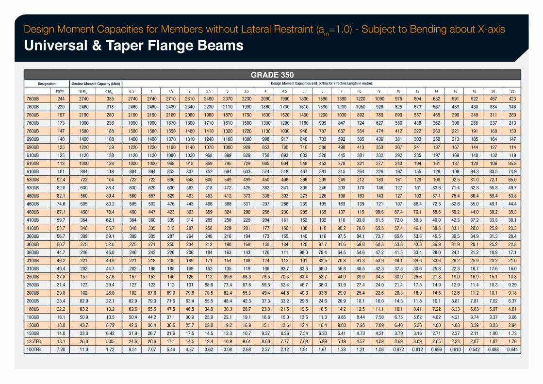
Design Moment Capacities for Members without Lateral Restraint (am=1.0) - Subject to Bending about X-axis
Universal & Taper Flange Beams
Designation
760UB
760UB
760UB
760UB
760UB
690UB
690UB
610UB
610UB
610UB
530UB
530UB
460UB
460UB
460UB
410UB
410UB
360UB
360UB
360UB
310UB
310UB
250UB
250UB
200UB
200UB
180UB
180UB
150UB
150UB
125TFB
100TFB
kg/m
244
220
197
173
147
140
125
125
113
101
92.4
82.0
82.1
74.6
67.1
59.7
53.7
56.7
50.7
44.7
46.2
40.4
37.3
31.4
29.8
25.4
22.2
18.1
18.0
14.0
13.1
7.20
Section Moment Capacity (kNm)
ø Msx
2740
2460
2190
1900
1580
1400
1220
1120
1000
884
722
630
560
505
450
364
340
309
275
246
221
202
157
127
102
82.9
63.2
50.9
43.7
33.0
26.0
11.0
ø Msy
355
318
280
236
188
188
159
158
138
118
104
88.4
89.4
80.2
70.4
62.1
55.7
59.1
52.0
45.0
49.9
44.7
37.6
29.4
28.0
22.1
13.2
10.5
8.72
6.42
5.05
1.72
0.5
2740
2460
2190
1900
1580
1400
1220
1120
1000
884
722
630
560
505
450
364
340
309
275
246
221
202
157
127
102
82.9
62.6
50.4
42.5
31.9
24.6
9.51
1
2740
2460
2190
1900
1580
1400
1220
1120
1000
884
722
629
557
502
447
360
335
305
271
242
218
198
152
123
97.6
79.0
55.5
44.2
36.4
26.7
20.6
7.07
1.5
2710
2430
2160
1870
1550
1370
1190
1090
968
853
690
600
529
476
423
339
313
287
255
226
205
185
140
112
89.0
71.6
47.5
37.1
30.5
21.6
17.1
5.44
2
2610
2340
2080
1800
1480
1310
1140
1030
918
807
648
562
493
443
393
314
287
264
234
206
189
169
126
101
79.6
63.4
40.5
30.9
25.7
17.5
14.5
4.37
2.5
2490
2230
1980
1710
1410
1240
1070
968
859
752
600
518
453
406
359
285
258
240
212
184
171
152
112
88.6
70.5
55.5
34.8
25.9
22.0
14.5
12.4
3.62
3
2370
2110
1870
1610
1320
1160
1000
899
795
694
549
472
412
368
324
256
229
216
190
163
154
135
99.6
77.4
62.4
48.4
30.3
22.1
19.2
12.3
10.9
3.08
GRADE 350 Design Moment Capacities ø Mb (kNm) for Effective Length in metres
3.5
2230
1990
1750
1500
1220
1080
929
829
729
633
499
425
373
331
290
229
201
194
169
143
138
119
88.3
67.6
55.3
42.3
26.7
19.1
16.9
10.7
9.61
2.68
4
2090
1860
1630
1390
1130
998
853
759
665
574
450
382
336
297
258
204
177
173
150
126
124
106
78.5
59.3
49.4
37.3
23.8
16.8
15.1
9.37
8.60
2.37
4.5
1960
1730
1520
1290
1030
917
780
693
604
518
406
341
303
266
230
181
156
155
134
111
112
93.7
70.3
52.4
44.5
33.2
21.5
15.0
13.6
8.36
7.77
2.12
5
1830
1610
1400
1180
946
840
710
632
548
467
366
305
273
239
205
162
138
140
120
98.0
101
83.6
63.4
46.7
40.3
29.8
19.5
13.5
12.4
7.54
7.08
1.91
6
1590
1390
1200
999
787
703
588
528
453
381
299
246
226
195
165
132
110
116
97.7
78.4
83.5
68.0
52.7
38.0
33.8
24.6
16.5
11.3
10.4
6.30
5.99
1.61
7
1390
1200
1030
847
657
592
490
445
378
315
249
203
190
163
137
110
90.2
97.5
81.6
64.5
70.8
56.8
44.9
31.9
29.0
20.9
14.2
9.65
9.03
5.41
5.19
1.38
8
1220
1050
892
724
554
505
413
381
321
264
212
170
163
139
115
93.8
76.0
84.1
69.8
54.6
61.3
48.5
39.0
27.4
25.4
18.1
12.5
8.44
7.95
4.73
4.57
1.21
9
1090
926
780
627
474
436
353
332
277
226
183
146
143
121
99.6
81.5
65.5
73.7
60.8
47.2
53.9
42.3
34.5
24.0
22.6
16.0
11.1
7.50
7.09
4.21
4.09
1.08
10
975
825
690
550
412
381
307
292
243
197
161
127
127
107
87.4
72.0
57.4
65.6
53.8
41.5
48.1
37.5
30.9
21.4
20.3
14.3
10.1
6.75
6.40
3.79
3.69
0.972
12
804
673
557
438
322
303
241
235
194
155
129
101
103
86.4
70.1
58.3
46.1
53.8
43.8
33.4
39.6
30.6
25.6
17.5
16.9
11.8
8.41
5.62
5.36
3.16
3.09
0.812
14
682
567
465
362
263
250
197
197
161
128
108
83.6
87.1
72.5
58.5
49.0
38.5
45.5
36.9
28.0
33.6
25.8
21.8
14.9
14.5
10.1
7.22
4.82
4.60
2.71
2.65
0.696
16
591
489
399
308
221
213
167
169
137
108
92.5
71.4
75.4
62.6
50.2
42.3
33.1
39.5
31.9
24.1
29.2
22.3
19.0
12.9
12.6
8.81
6.33
4.21
4.03
2.37
2.33
0.610
18
522
430
349
268
191
185
144
148
120
94.3
81.0
62.3
66.4
55.0
44.0
37.2
29.0
34.9
28.1
21.2
25.9
19.7
16.9
11.4
11.2
7.81
5.63
3.74
3.59
2.11
2.07
0.542
20
467
384
311
237
168
164
127
132
106
83.5
72.1
55.3
59.4
49.1
39.2
33.3
25.9
31.3
25.2
18.9
23.2
17.6
15.1
10.3
10.1
7.02
5.07
3.37
3.23
1.90
1.87
0.488
22
423
346
280
213
150
147
114
119
95.8
74.9
65.0
49.7
53.8
44.4
35.3
30.1
23.3
28.4
22.8
17.1
21.0
16.0
13.8
9.29
9.18
6.37
4.61
3.06
2.94
1.73
1.70
0.444
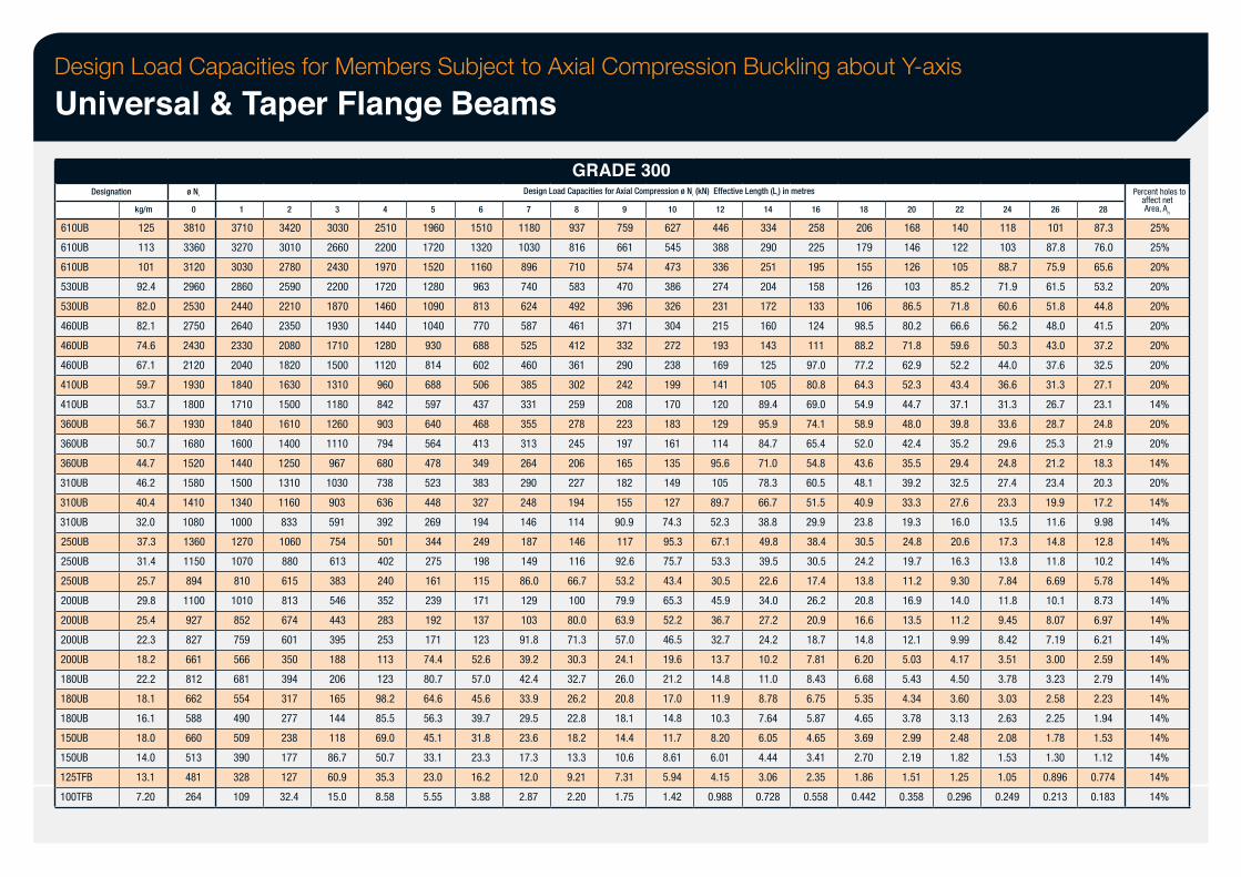
Design Load Capacities for Members Subject to Axial Compression Buckling about Y-axis
Universal & Taper Flange Beams
Designation
610UB
610UB
610UB
530UB
530UB
460UB
460UB
460UB
410UB
410UB
360UB
360UB
360UB
310UB
310UB
310UB
250UB
250UB
250UB
200UB
200UB
200UB
200UB
180UB
180UB
180UB
150UB
150UB
125TFB
100TFB
kg/m
125
113
101
92.4
82.0
82.1
74.6
67.1
59.7
53.7
56.7
50.7
44.7
46.2
40.4
32.0
37.3
31.4
25.7
29.8
25.4
22.3
18.2
22.2
18.1
16.1
18.0
14.0
13.1
7.20
ø Ns
0
3810
3360
3120
2960
2530
2750
2430
2120
1930
1800
1930
1680
1520
1580
1410
1080
1360
1150
894
1100
927
827
661
812
662
588
660
513
481
264
1
3710
3270
3030
2860
2440
2640
2330
2040
1840
1710
1840
1600
1440
1500
1340
1000
1270
1070
810
1010
852
759
566
681
554
490
509
390
328
109
2
3420
3010
2780
2590
2210
2350
2080
1820
1630
1500
1610
1400
1250
1310
1160
833
1060
880
615
813
674
601
350
394
317
277
238
177
127
32.4
3
3030
2660
2430
2200
1870
1930
1710
1500
1310
1180
1260
1110
967
1030
903
591
754
613
383
546
443
395
188
206
165
144
118
86.7
60.9
15.0
4
2510
2200
1970
1720
1460
1440
1280
1120
960
842
903
794
680
738
636
392
501
402
240
352
283
253
113
123
98.2
85.5
69.0
50.7
35.3
8.58
5
1960
1720
1520
1280
1090
1040
930
814
688
597
640
564
478
523
448
269
344
275
161
239
192
171
74.4
80.7
64.6
56.3
45.1
33.1
23.0
5.55
6
1510
1320
1160
963
813
770
688
602
506
437
468
413
349
383
327
194
249
198
115
171
137
123
52.6
57.0
45.6
39.7
31.8
23.3
16.2
3.88
GRADE 300 Design Load Capacities for Axial Compression ø Nc (kN) Effective Length (Le) in metres
7
1180
1030
896
740
624
587
525
460
385
331
355
313
264
290
248
146
187
149
86.0
129
103
91.8
39.2
42.4
33.9
29.5
23.6
17.3
12.0
2.87
8
937
816
710
583
492
461
412
361
302
259
278
245
206
227
194
114
146
116
66.7
100
80.0
71.3
30.3
32.7
26.2
22.8
18.2
13.3
9.21
2.20
9
759
661
574
470
396
371
332
290
242
208
223
197
165
182
155
90.9
117
92.6
53.2
79.9
63.9
57.0
24.1
26.0
20.8
18.1
14.4
10.6
7.31
1.75
10
627
545
473
386
326
304
272
238
199
170
183
161
135
149
127
74.3
95.3
75.7
43.4
65.3
52.2
46.5
19.6
21.2
17.0
14.8
11.7
8.61
5.94
1.42
12
446
388
336
274
231
215
193
169
141
120
129
114
95.6
105
89.7
52.3
67.1
53.3
30.5
45.9
36.7
32.7
13.7
14.8
11.9
10.3
8.20
6.01
4.15
0.988
14
334
290
251
204
172
160
143
125
105
89.4
95.9
84.7
71.0
78.3
66.7
38.8
49.8
39.5
22.6
34.0
27.2
24.2
10.2
11.0
8.78
7.64
6.05
4.44
3.06
0.728
16
258
225
195
158
133
124
111
97.0
80.8
69.0
74.1
65.4
54.8
60.5
51.5
29.9
38.4
30.5
17.4
26.2
20.9
18.7
7.81
8.43
6.75
5.87
4.65
3.41
2.35
0.558
18
206
179
155
126
106
98.5
88.2
77.2
64.3
54.9
58.9
52.0
43.6
48.1
40.9
23.8
30.5
24.2
13.8
20.8
16.6
14.8
6.20
6.68
5.35
4.65
3.69
2.70
1.86
0.442
20
168
146
126
103
86.5
80.2
71.8
62.9
52.3
44.7
48.0
42.4
35.5
39.2
33.3
19.3
24.8
19.7
11.2
16.9
13.5
12.1
5.03
5.43
4.34
3.78
2.99
2.19
1.51
0.358
22
140
122
105
85.2
71.8
66.6
59.6
52.2
43.4
37.1
39.8
35.2
29.4
32.5
27.6
16.0
20.6
16.3
9.30
14.0
11.2
9.99
4.17
4.50
3.60
3.13
2.48
1.82
1.25
0.296
24
118
103
88.7
71.9
60.6
56.2
50.3
44.0
36.6
31.3
33.6
29.6
24.8
27.4
23.3
13.5
17.3
13.8
7.84
11.8
9.45
8.42
3.51
3.78
3.03
2.63
2.08
1.53
1.05
0.249
26
101
87.8
75.9
61.5
51.8
48.0
43.0
37.6
31.3
26.7
28.7
25.3
21.2
23.4
19.9
11.6
14.8
11.8
6.69
10.1
8.07
7.19
3.00
3.23
2.58
2.25
1.78
1.30
0.896
0.213
28
87.3
76.0
65.6
53.2
44.8
41.5
37.2
32.5
27.1
23.1
24.8
21.9
18.3
20.3
17.2
9.98
12.8
10.2
5.78
8.73
6.97
6.21
2.59
2.79
2.23
1.94
1.53
1.12
0.774
0.183
Percent holes to affect net Area, An
25%
25%
20%
20%
20%
20%
20%
20%
20%
14%
20%
20%
14%
20%
14%
14%
14%
14%
14%
14%
14%
14%
14%
14%
14%
14%
14%
14%
14%
14%
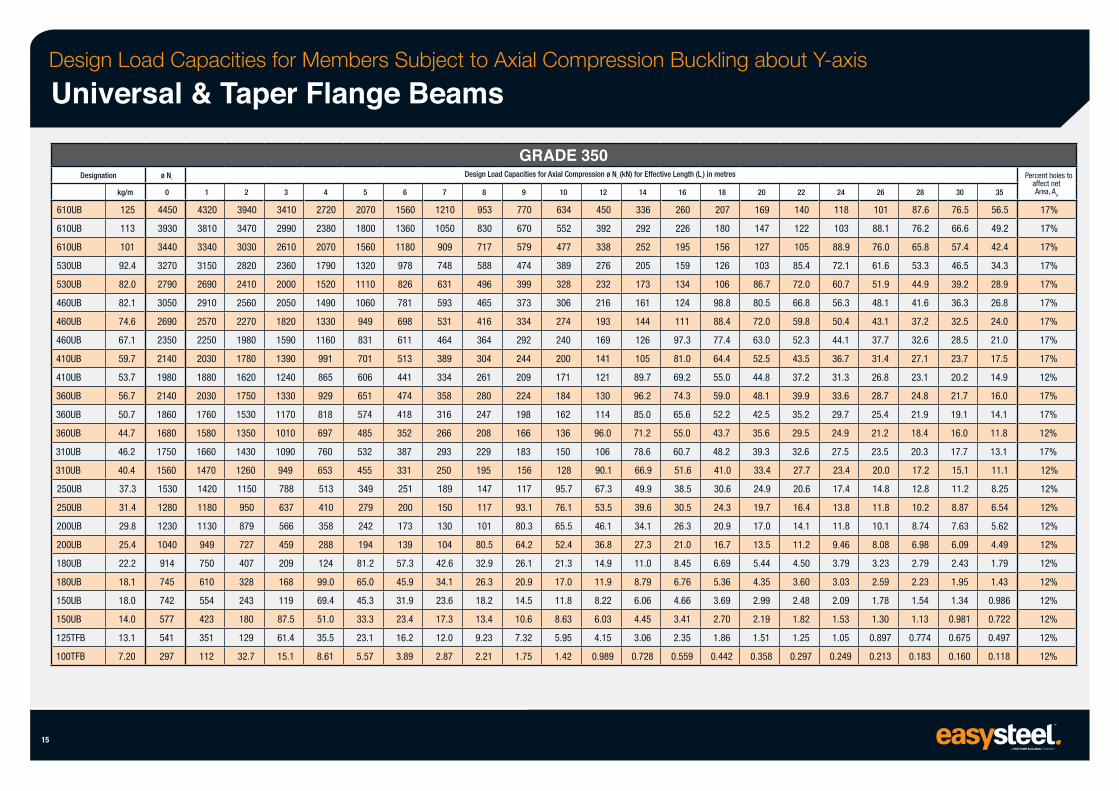
Design Load Capacities for Members Subject to Axial Compression Buckling about Y-axis
Universal & Taper Flange Beams
Designation
610UB
610UB
610UB
530UB
530UB
460UB
460UB
460UB
410UB
410UB
360UB
360UB
360UB
310UB
310UB
250UB
250UB
200UB
200UB
180UB
180UB
150UB
150UB
125TFB
100TFB
15
kg/m
125
113
101
92.4
82.0
82.1
74.6
67.1
59.7
53.7
56.7
50.7
44.7
46.2
40.4
37.3
31.4
29.8
25.4
22.2
18.1
18.0
14.0
13.1
7.20
ø Ns
0
4450
3930
3440
3270
2790
3050
2690
2350
2140
1980
2140
1860
1680
1750
1560
1530
1280
1230
1040
914
745
742
577
541
297
1
4320
3810
3340
3150
2690
2910
2570
2250
2030
1880
2030
1760
1580
1660
1470
1420
1180
1130
949
750
610
554
423
351
112
2
3940
3470
3030
2820
2410
2560
2270
1980
1780
1620
1750
1530
1350
1430
1260
1150
950
879
727
407
328
243
180
129
32.7
3
3410
2990
2610
2360
2000
2050
1820
1590
1390
1240
1330
1170
1010
1090
949
788
637
566
459
209
168
119
87.5
61.4
15.1
4
2720
2380
2070
1790
1520
1490
1330
1160
991
865
929
818
697
760
653
513
410
358
288
124
99.0
69.4
51.0
35.5
8.61
5
2070
1800
1560
1320
1110
1060
949
831
701
606
651
574
485
532
455
349
279
242
194
81.2
65.0
45.3
33.3
23.1
5.57
6
1560
1360
1180
978
826
781
698
611
513
441
474
418
352
387
331
251
200
173
139
57.3
45.9
31.9
23.4
16.2
3.89
7
1210
1050
909
748
631
593
531
464
389
334
358
316
266
293
250
189
150
130
104
42.6
34.1
23.6
17.3
12.0
2.87
GRADE 350 Design Load Capacities for Axial Compression ø Nc (kN) for Effective Length (Le) in metres
8
953
830
717
588
496
465
416
364
304
261
280
247
208
229
195
147
117
101
80.5
32.9
26.3
18.2
13.4
9.23
2.21
9
770
670
579
474
399
373
334
292
244
209
224
198
166
183
156
117
93.1
80.3
64.2
26.1
20.9
14.5
10.6
7.32
1.75
10
634
552
477
389
328
306
274
240
200
171
184
162
136
150
128
95.7
76.1
65.5
52.4
21.3
17.0
11.8
8.63
5.95
1.42
12
450
392
338
276
232
216
193
169
141
121
130
114
96.0
106
90.1
67.3
53.5
46.1
36.8
14.9
11.9
8.22
6.03
4.15
0.989
14
336
292
252
205
173
161
144
126
105
89.7
96.2
85.0
71.2
78.6
66.9
49.9
39.6
34.1
27.3
11.0
8.79
6.06
4.45
3.06
0.728
16
260
226
195
159
134
124
111
97.3
81.0
69.2
74.3
65.6
55.0
60.7
51.6
38.5
30.5
26.3
21.0
8.45
6.76
4.66
3.41
2.35
0.559
18
207
180
156
126
106
98.8
88.4
77.4
64.4
55.0
59.0
52.2
43.7
48.2
41.0
30.6
24.3
20.9
16.7
6.69
5.36
3.69
2.70
1.86
0.442
20
169
147
127
103
86.7
80.5
72.0
63.0
52.5
44.8
48.1
42.5
35.6
39.3
33.4
24.9
19.7
17.0
13.5
5.44
4.35
2.99
2.19
1.51
0.358
22
140
122
105
85.4
72.0
66.8
59.8
52.3
43.5
37.2
39.9
35.2
29.5
32.6
27.7
20.6
16.4
14.1
11.2
4.50
3.60
2.48
1.82
1.25
0.297
24
118
103
88.9
72.1
60.7
56.3
50.4
44.1
36.7
31.3
33.6
29.7
24.9
27.5
23.4
17.4
13.8
11.8
9.46
3.79
3.03
2.09
1.53
1.05
0.249
26
101
88.1
76.0
61.6
51.9
48.1
43.1
37.7
31.4
26.8
28.7
25.4
21.2
23.5
20.0
14.8
11.8
10.1
8.08
3.23
2.59
1.78
1.30
0.897
0.213
28
87.6
76.2
65.8
53.3
44.9
41.6
37.2
32.6
27.1
23.1
24.8
21.9
18.4
20.3
17.2
12.8
10.2
8.74
6.98
2.79
2.23
1.54
1.13
0.774
0.183
30
76.5
66.6
57.4
46.5
39.2
36.3
32.5
28.5
23.7
20.2
21.7
19.1
16.0
17.7
15.1
11.2
8.87
7.63
6.09
2.43
1.95
1.34
0.981
0.675
0.160
35
56.5
49.2
42.4
34.3
28.9
26.8
24.0
21.0
17.5
14.9
16.0
14.1
11.8
13.1
11.1
8.25
6.54
5.62
4.49
1.79
1.43
0.986
0.722
0.497
0.118
Percent holes to affect net Area, An
17%
17%
17%
17%
17%
17%
17%
17%
17%
12%
17%
17%
12%
17%
12%
12%
12%
12%
12%
12%
12%
12%
12%
12%
12%
Universal Columns
16
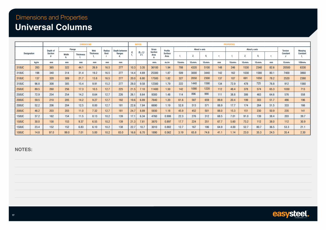
Dimensions and Properties
Universal Columns
Designation
310UC
310UC
310UC
310UC
250UC
250UC
200UC
200UC
200UC
150UC
150UC
150UC
100UC
kg/m
283
198
137
96.8
89.5
72.9
59.5
52.2
46.2
37.2
30.0
23.4
14.8
NOTES:
17
Depth of Section
d
mm
365
340
320
308
260
254
210
206
203
162
158
152
97.0
Flange
Width bf
mm
322
314
309
305
256
254
205
204
203
154
153
152
99.0
DIMENSIONS
Thickness tf
mm
44.1
31.4
21.7
15.4
17.3
14.2
14.2
12.5
11.0
11.5
9.37
6.83
7.01
Web Thickness
tw
mm
26.9
19.2
13.8
9.91
10.5
8.64
9.27
8.00
7.32
8.13
6.55
6.10
5.00
Radius Root
r
mm
16.5
16.5
16.5
15.2
12.7
12.7
12.7
12.7
12.7
10.2
10.2
10.2
10.2
Depth between flanges
d1
mm
277
277
277
277
225
226
182
181
181
139
139
138
83.0
RATIOS
d1
tw
10.3
14.4
20.0
28.0
21.5
26.1
19.6
22.6
24.7
17.1
21.3
22.7
16.6
(bf - tw) 2 tf
3.35
4.69
6.80
9.58
7.10
8.64
6.89
7.84
8.89
6.34
7.81
10.7
6.70
Gross Section
Area A
mm2
36100
25300
17500
12300
11400
9300
7640
6690
5930
4760
3870
3010
1890
Profile Surface
Area
m2/m
1.94
1.87
1.82
1.79
1.50
1.48
1.20
1.19
1.18
0.906
0.897
0.882
0.562
Ix
106mm4
788
509
327
222
142
114
61.6
52.8
45.9
22.3
17.7
12.7
3.19
About x-axis
Zx
103mm3
4320
3000
2050
1440
1090
896
587
513
452
276
224
167
65.8
Sx
103mm3
5100
3440
2300
1590
1220
990
659
571
501
312
251
186
74.6
rx
PROPERTIES
mm
148
142
137
134
112
111
89.8
88.9
88.0
68.5
67.7
64.9
41.1
Iy
106mm4
246
162
107
72.9
48.4
38.8
20.4
17.7
15.3
7.01
5.60
4.00
1.14
About y-axis
Zy
103mm3
1530
1030
691
478
378
306
199
174
151
91.0
73.2
52.7
23.0
Sy
103mm3
2340
1580
1050
725
574
463
303
264
230
139
112
80.7
35.3
ry
mm
82.6
80.1
78.2
76.8
65.3
64.6
51.7
51.5
50.9
38.4
38.0
36.5
24.5
Torsion Constant
J
103mm4
20500
7400
2520
912
1030
576
486
333
235
203
112
53.3
35.4
Warping Constant
Iw
109mm6
6330
3860
2380
1560
713
558
196
166
141
39.7
30.9
21.1
2.30
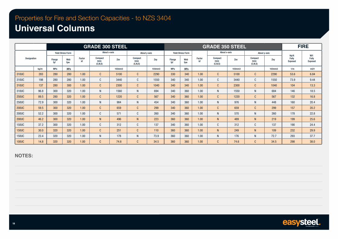
Properties for Fire and Section Capacities - to NZS 3404
Universal Columns
Designation
310UC
310UC
310UC
310UC
250UC
250UC
200UC
200UC
200UC
150UC
150UC
150UC
100UC
NOTES:
18
kg/m
283
198
137
96.8
89.5
72.9
59.5
52.2
46.2
37.2
30.0
23.4
14.8
Yield Stress Form
Flange fyf
MPa
280
280
280
300
280
300
300
300
300
300
320
320
320
Web fyw
MPa
280
280
300
320
320
320
320
320
320
320
320
320
320
GRADE 300 STEEL About x-axis
Factor kf
1.00
1.00
1.00
1.00
1.00
1.00
1.00
1.00
1.00
1.00
1.00
1.00
1.00
Compact ness
(C,N,S)
C
C
C
N
C
N
C
C
N
C
C
N
C
Zex
103mm3
5100
3440
2300
1560
1220
984
659
571
496
312
251
178
74.6
About y-axis
Compact ness
(C,N,S)
C
C
C
N
C
N
C
C
N
C
C
N
C
Zey
103mm3
2290
1550
1040
694
567
454
299
260
223
137
110
73.9
34.5
Yield Stress Form
Flange fyf
MPa
330
340
340
340
340
340
340
340
360
340
360
360
360
Web fyw
MPa
340
340
340
360
360
360
360
360
360
360
360
360
360
GRADE 350 STEEL About x-axis
Factor kf
1.00
1.00
1.00
1.00
1.00
1.00
1.00
1.00
1.00
1.00
1.00
1.00
1.00
Compact ness
(C,N,S)
C
C
C
N
C
N
C
N
N
C
N
N
C
Zex
103mm3
5100
3440
2300
1550
1220
976
659
570
489
312
249
176
74.6
About y-axis
Compact ness
(C,N,S)
C
C
C
N
C
N
C
N
N
C
N
N
C
Zey
103mm3
2290
1550
1040
684
567
448
299
260
219
137
109
72.7
34.5
Hp/A Fully
Exposed
FIRE
1/m
53.6
73.9
104
146
132
160
157
178
199
190
232
293
298
M/t Fully
Exposed
m2/t
6.84
9.44
13.3
18.5
16.8
20.4
20.2
22.8
25.6
24.4
29.9
37.7
38.0
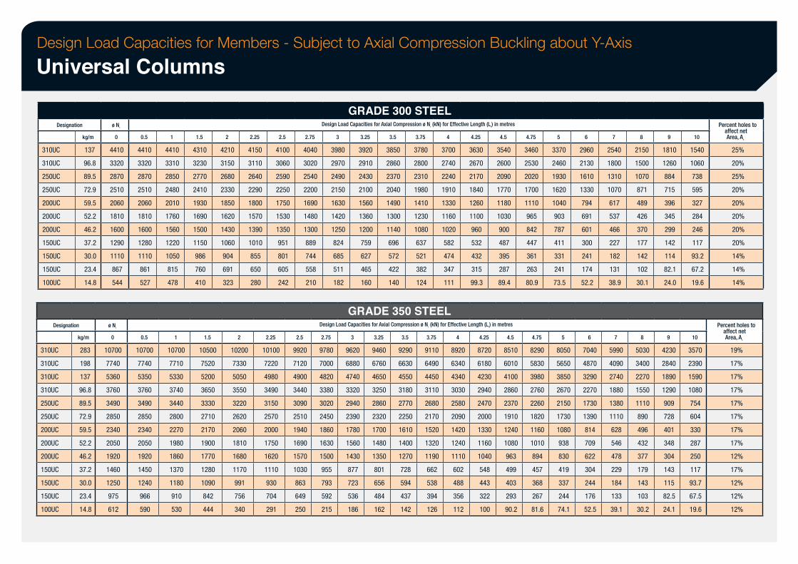
Design Load Capacities for Members - Subject to Axial Compression Buckling about Y-Axis
Universal Columns
Designation
310UC
310UC
250UC
250UC
200UC
200UC
200UC
150UC
150UC
150UC
100UC
kg/m
137
96.8
89.5
72.9
59.5
52.2
46.2
37.2
30.0
23.4
14.8
Designation
310UC
310UC
310UC
310UC
250UC
250UC
200UC
200UC
200UC
150UC
150UC
150UC
100UC
kg/m
283
198
137
96.8
89.5
72.9
59.5
52.2
46.2
37.2
30.0
23.4
14.8
ø Ns
0
4410
3320
2870
2510
2060
1810
1600
1290
1110
867
544
ø Ns
0
10700
7740
5360
3760
3490
2850
2340
2050
1920
1460
1250
975
612
0.5
4410
3320
2870
2510
2060
1810
1600
1280
1110
861
527
0.5
10700
7740
5350
3760
3490
2850
2340
2050
1920
1450
1240
966
590
1
4410
3310
2850
2480
2010
1760
1560
1220
1050
815
478
1
10700
7710
5330
3740
3440
2800
2270
1980
1860
1370
1180
910
530
1.5
4310
3230
2770
2410
1930
1690
1500
1150
986
760
410
2
4210
3150
2680
2330
1850
1620
1430
1060
1.5
10500
7520
5200
3650
3330
2710
2170
1900
1770
1280
1090
842
444
904
691
323
2
2.25
4150
3110
2640
2290
1800
1570
1390
1010
855
650
280
10200
7330
5050
3550
3220
2620
2060
1810
1680
1170
991
756
340
2.5
4100
3060
2590
2250
1750
1530
1350
2.25
951
801
605
242
10100
7220
4980
3490
3150
2570
2000
1750
1620
1110
930
704
291
2.75
4040
3020
2540
2200
1690
1480
1300
889
744
558
210
2.5
9920
7120
4900
3440
3090
2510
1940
1690
1570
1030
863
649
250
GRADE 300 STEEL Design Load Capacities for Axial Compression ø Nc (kN) for Effective Length (Le) in metres
3
3980
2970
2490
2150
1630
1420
1250
824
685
511
182
3.25
3920
2910
2430
2100
1560
1360
1200
759
627
465
160
3.5
3850
2860
2370
2040
1490
1300
1140
696
572
422
140
3.75
3780
2800
2310
1980
1410
1230
1080
637
521
382
124
4
3700
2740
2240
1910
1330
1160
1020
582
474
347
111
GRADE 350 STEEL Design Load Capacities for Axial Compression ø Nc (kN) for Effective Length (Le) in metres
4.25
3630
2670
2170
1840
1260
1100
960
532
432
315
99.3
4.5
3540
2600
2090
1770
1180
1030
900
487
395
287
89.4
2.75
9780
7000
4820
3380
3020
2450
1860
1630
1500
955
793
592
215
3
9620
6880
4740
3320
2940
2390
1780
1560
1430
877
723
536
186
3.25
9460
6760
4650
3250
2860
2320
1700
1480
1350
801
656
484
162
3.5
9290
6630
4550
3180
2770
2250
1610
1400
1270
728
594
437
142
3.75
9110
6490
4450
3110
2680
2170
1520
1320
1190
662
538
394
126
4
8920
6340
4340
3030
2580
2090
1420
1240
1110
602
488
356
112
4.25
8720
6180
4230
2940
2470
2000
1330
1160
1040
548
443
322
100
4.75
3460
2530
2020
1700
1110
4.5
8510
6010
4100
2860
2370
1910
1240
1080
963
499
403
293
90.2
965
842
447
361
263
80.9
4.75
8290
5830
3980
2760
2260
1820
1160
1010
894
457
368
267
81.6
5
3370
2460
1930
1620
1040
903
787
411
331
241
73.5
5
8050
5650
3850
2670
2150
1730
1080
938
830
419
337
244
74.1
6
2960
2130
1610
1330
794
691
601
300
241
174
52.2
6
7040
4870
3290
2270
1730
1390
814
709
622
304
244
176
52.5
7
2540
1800
1310
1070
617
537
466
227
182
131
38.9
7
5990
4090
2740
1880
1380
1110
628
546
478
229
184
133
39.1
8
2150
1500
1070
871
489
426
370
177
142
102
30.1
8
5030
3400
2270
1550
1110
890
496
432
377
179
143
103
30.2
9
1810
1260
884
715
396
345
299
142
114
82.1
24.0
9
4230
2840
1890
1290
909
728
401
348
304
143
115
82.5
24.1
10
1540
1060
738
595
327
284
246
117
93.2
67.2
19.6
10
3570
2390
1590
1080
754
604
330
287
250
117
93.7
67.5
19.6
Percent holes to affect net Area, An
25%
20%
25%
20%
20%
20%
20%
20%
14%
14%
14%
Percent holes to affect net Area, An
19%
17%
17%
17%
17%
17%
17%
17%
12%
17%
12%
12%
12%
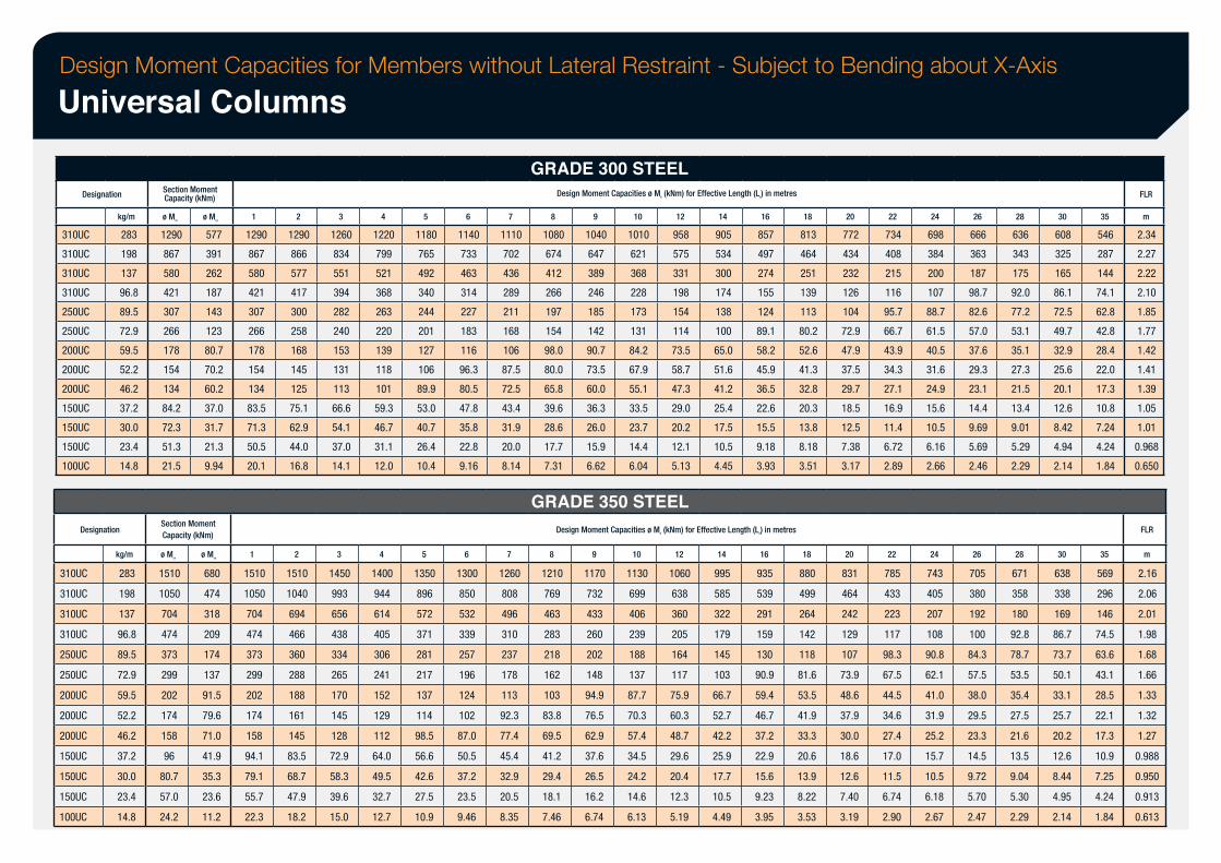
Design Moment Capacities for Members without Lateral Restraint - Subject to Bending about X-Axis
Universal Columns
Designation
310UC
310UC
310UC
310UC
250UC
250UC
200UC
200UC
200UC
150UC
150UC
150UC
100UC
kg/m
283
198
137
96.8
89.5
72.9
59.5
52.2
46.2
37.2
30.0
23.4
14.8
Designation
310UC
310UC
310UC
310UC
250UC
250UC
200UC
200UC
200UC
150UC
150UC
150UC
100UC
kg/m
283
198
137
96.8
89.5
72.9
59.5
52.2
46.2
37.2
30.0
23.4
14.8
Section Moment Capacity (kNm)
ø Msx
1290
867
580
421
307
266
178
154
134
84.2
72.3
51.3
21.5
ø Msy
577
391
262
187
143
123
80.7
70.2
60.2
37.0
31.7
21.3
9.94
Section Moment Capacity (kNm)
ø Msx
1510
1050
704
474
373
299
202
174
158
96
80.7
57.0
24.2
ø Msy
680
474
318
209
174
137
91.5
79.6
71.0
41.9
35.3
23.6
11.2
1
1290
867
580
421
307
266
178
154
134
83.5
71.3
50.5
20.1
1
1510
1050
704
474
373
299
202
174
158
94.1
79.1
55.7
22.3
2
1290
866
577
417
300
258
168
145
125
75.1
62.9
44.0
16.8
2
1510
1040
694
466
360
288
188
161
145
83.5
68.7
47.9
18.2
3
1260
834
551
394
282
240
153
131
113
66.6
54.1
37.0
14.1
3
1450
993
656
438
334
265
170
145
128
72.9
58.3
39.6
15.0
4
1220
799
521
368
263
220
139
118
101
59.3
46.7
31.1
12.0
4
1400
944
614
405
306
241
152
129
112
64.0
49.5
32.7
12.7
5
1180
765
492
340
244
201
127
106
89.9
53.0
40.7
26.4
10.4
5
1350
896
572
371
281
217
137
114
98.5
56.6
42.6
27.5
10.9
6
1140
733
463
314
227
183
116
96.3
80.5
47.8
35.8
22.8
9.16
6
1300
850
532
339
257
196
124
102
87.0
50.5
37.2
23.5
9.46
7
1110
702
436
289
211
168
106
87.5
72.5
43.4
31.9
20.0
8.14
7
1260
808
496
310
237
178
113
92.3
77.4
45.4
32.9
20.5
8.35
GRADE 300 STEEL Design Moment Capacities ø Mb (kNm) for Effective Length (Le) in metres
8
1080
674
412
266
197
154
98.0
80.0
65.8
39.6
28.6
17.7
7.31
9
1040
647
389
246
185
142
90.7
73.5
60.0
36.3
26.0
15.9
6.62
10
1010
621
368
228
173
131
84.2
67.9
55.1
33.5
23.7
14.4
6.04
12
958
575
331
198
154
114
73.5
58.7
47.3
29.0
20.2
12.1
5.13
GRADE 350 STEEL
14
905
534
300
174
138
100
65.0
51.6
41.2
25.4
17.5
10.5
4.45
16
857
497
274
155
124
89.1
58.2
45.9
36.5
22.6
15.5
9.18
3.93
18
813
464
251
139
113
80.2
52.6
41.3
32.8
20.3
13.8
8.18
3.51
Design Moment Capacities ø Mb (kNm) for Effective Length (Le) in metres
8
1210
769
463
283
218
162
103
83.8
69.5
41.2
29.4
18.1
7.46
9
1170
732
433
260
202
148
94.9
76.5
62.9
37.6
26.5
16.2
6.74
10
1130
699
406
239
188
137
87.7
70.3
57.4
34.5
24.2
14.6
6.13
12
1060
638
360
205
164
117
75.9
60.3
48.7
29.6
20.4
12.3
5.19
14
995
585
322
179
145
103
66.7
52.7
42.2
25.9
17.7
10.5
4.49
16
935
539
291
159
130
90.9
59.4
46.7
37.2
22.9
15.6
9.23
3.95
18
880
499
264
142
118
81.6
53.5
41.9
33.3
20.6
13.9
8.22
3.53
20
772
434
232
126
104
72.9
47.9
37.5
29.7
18.5
12.5
7.38
3.17
20
831
464
242
129
107
73.9
48.6
37.9
30.0
18.6
12.6
7.40
3.19
22
734
408
215
116
95.7
66.7
43.9
34.3
27.1
16.9
11.4
6.72
2.89
22
785
433
223
117
98.3
67.5
44.5
34.6
27.4
17.0
11.5
6.74
2.90
24
698
384
200
107
88.7
61.5
40.5
31.6
24.9
15.6
10.5
6.16
2.66
24
743
405
207
108
90.8
62.1
41.0
31.9
25.2
15.7
10.5
6.18
2.67
26
666
363
187
98.7
82.6
57.0
37.6
29.3
23.1
14.4
9.69
5.69
2.46
26
705
380
192
100
84.3
57.5
38.0
29.5
23.3
14.5
9.72
5.70
2.47
28
636
343
175
92.0
77.2
53.1
35.1
27.3
21.5
13.4
9.01
5.29
2.29
28
671
358
180
92.8
78.7
53.5
35.4
27.5
21.6
13.5
9.04
5.30
2.29
30
608
325
165
86.1
72.5
49.7
32.9
25.6
20.1
12.6
8.42
4.94
2.14
30
638
338
169
86.7
73.7
50.1
33.1
25.7
20.2
12.6
8.44
4.95
2.14
35
546
287
144
74.1
62.8
42.8
28.4
22.0
17.3
10.8
7.24
4.24
1.84
35
569
296
146
74.5
63.6
43.1
28.5
22.1
17.3
10.9
7.25
4.24
1.84
FLR
m
2.34
2.27
2.22
2.10
1.85
1.77
1.42
1.41
1.39
1.05
1.01
0.968
0.650
FLR
m
2.16
2.06
2.01
1.98
1.68
1.66
1.33
1.32
1.27
0.988
0.950
0.913
0.613
Standard Welded Columns & Beams
21
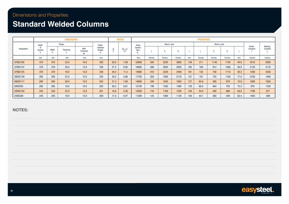
Dimensions and Properties
Standard Welded Columns
Designation
370SC185
370SC147
370SC125
295SC139
295SC117
295SC95
245SC104
245SC89
NOTES:
22
Depth of
Section d
mm
370
370
370
295
295
295
245
245
Width bf
mm
370
370
370
295
295
295
245
245
DIMENSIONS
Flange
Thickness tf
mm
25.0
20.0
16.0
25.0
20.0
16.0
22.0
18.0
Web Thickness
tw
mm
16.0
12.0
12.0
12.0
12.0
10.0
12.0
12.0
Depth between flanges
d1
mm
320
330
338
245
255
263
201
209
d1 tw
RATIOS
20.0
27.5
28.2
20.4
21.3
26.3
16.8
17.4
(bf - tw) 2 tf
7.08
8.95
11.2
5.66
7.08
8.91
5.30
6.47
Gross Section
Area Ag
mm2
23600
18800
15900
17700
14900
12100
13200
11300
Ix
106mm4
595
490
410
284
240
199
143
123
About x-axis
Zx
103mm3
3220
2650
2220
1930
1630
1350
1160
1000
Sx
103mm3
3600
2920
2440
2170
1820
1490
1320
1130
rx
mm
159
162
161
127
127
128
104
104
PROPERTIES
Iy
106mm4
211
169
135
107
85.6
68.5
54.0
44.1
About y-axis
Zy
103mm3
1140
913
730
725
580
464
440
360
Sy
103mm3
1730
1380
1110
1100
879
703
668
548
ry
mm
94.6
94.9
92.2
77.8
75.9
75.3
64.0
62.4
Torsion Constant
J
103mm4
4210
2130
1200
3100
1680
879
1790
1050
Warping Constant
Iw
109mm6
6280
5170
4230
1950
1620
1330
671
569
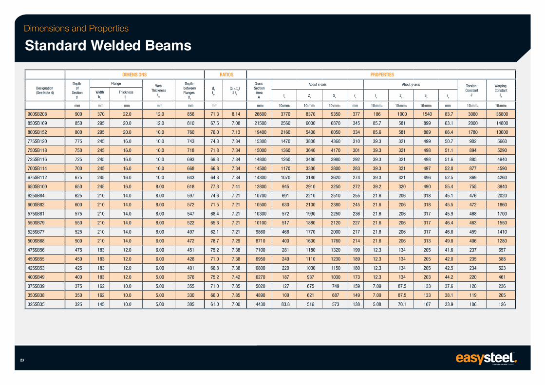
Dimensions and Properties
Standard Welded Beams
Designation (See Note 4)
900SB208
850SB169
800SB152
775SB120
750SB118
725SB116
700SB114
675SB112
650SB100
625SB84
600SB82
575SB81
550SB79
525SB77
500SB68
475SB56
450SB55
425SB53
400SB49
375SB39
350SB38
325SB35
23
Depth of
Section d
mm
900
850
800
775
750
725
700
675
650
625
600
575
550
525
500
475
450
425
400
375
350
325
Width bf
mm
370
295
295
245
245
245
245
245
245
210
210
210
210
210
210
183
183
183
183
162
162
145
DIMENSIONS
Flange
Thickness tf
mm
22.0
20.0
20.0
16.0
16.0
16.0
16.0
16.0
16.0
14.0
14.0
14.0
14.0
14.0
14.0
12.0
12.0
12.0
12.0
10.0
10.0
10.0
Web Thickness
tw
mm
12.0
12.0
10.0
10.0
10.0
10.0
10.0
10.0
8.00
8.00
8.00
8.00
8.00
8.00
6.00
6.00
6.00
6.00
5.00
5.00
5.00
5.00
Depth between Flanges
d1
mm
856
810
760
743
718
693
668
643
618
597
572
547
522
497
472
451
426
401
376
355
330
305
RATIOS
d1
tw
mm
71.3
67.5
76.0
74.3
71.8
69.3
66.8
64.3
77.3
74.6
71.5
68.4
65.3
62.1
78.7
75.2
71.0
66.8
75.2
71.0
66.0
61.0
(bf - tw) 2 tf
8.14
7.08
7.13
7.34
7.34
7.34
7.34
7.34
7.41
7.21
7.21
7.21
7.21
7.21
7.29
7.38
7.38
7.38
7.42
7.85
7.85
7.00
Gross Section
Area A
mm2
26600
21500
19400
15300
15000
14800
14500
14300
12800
10700
10500
10300
10100
9860
8710
7100
6950
6800
6270
5020
4890
4430
Ix
106mm4
3770
2560
2160
1470
1360
1260
1170
1070
945
691
630
572
517
466
400
281
249
220
187
127
109
83.8
About x-axis
Zx
103mm3
8370
6030
5400
3800
3640
3480
3330
3180
2910
2210
2100
1990
1880
1770
1600
1180
1110
1030
937
675
621
516
Sx
103mm3
9350
6870
6050
4360
4170
3980
3800
3620
3250
2510
2380
2250
2120
2000
1760
1320
1230
1150
1030
749
687
573
rx
mm
377
345
334
310
301
292
283
274
272
255
245
236
227
217
214
199
189
180
173
159
149
138
PROPERTIES
Iy
103mm4
186
85.7
85.6
39.3
39.3
39.3
39.3
39.3
39.2
21.6
21.6
21.6
21.6
21.6
21.6
12.3
12.3
12.3
12.3
7.09
7.09
5.08
About y-axis
Zy
103mm3
1000
581
581
321
321
321
321
321
320
206
206
206
206
206
206
134
134
134
134
87.5
87.5
70.1
Sy
103mm3
1540
899
889
499
498
498
497
496
490
318
318
317
317
317
313
205
205
205
203
133
133
107
ry
mm
83.7
63.1
66.4
50.7
51.1
51.6
52.0
52.5
55.4
45.1
45.5
45.9
46.4
46.8
49.8
41.6
42.0
42.5
44.2
37.6
38.1
33.9
Torsion Constant
J
103mm4
3060
2000
1780
902
894
885
877
869
755
476
472
468
463
459
406
237
235
234
220
120
119
106
Warping Constant
Iw
109mm6
35800
14800
13000
5660
5290
4940
4590
4260
3940
2020
1860
1700
1550
1410
1280
657
588
523
461
236
205
126
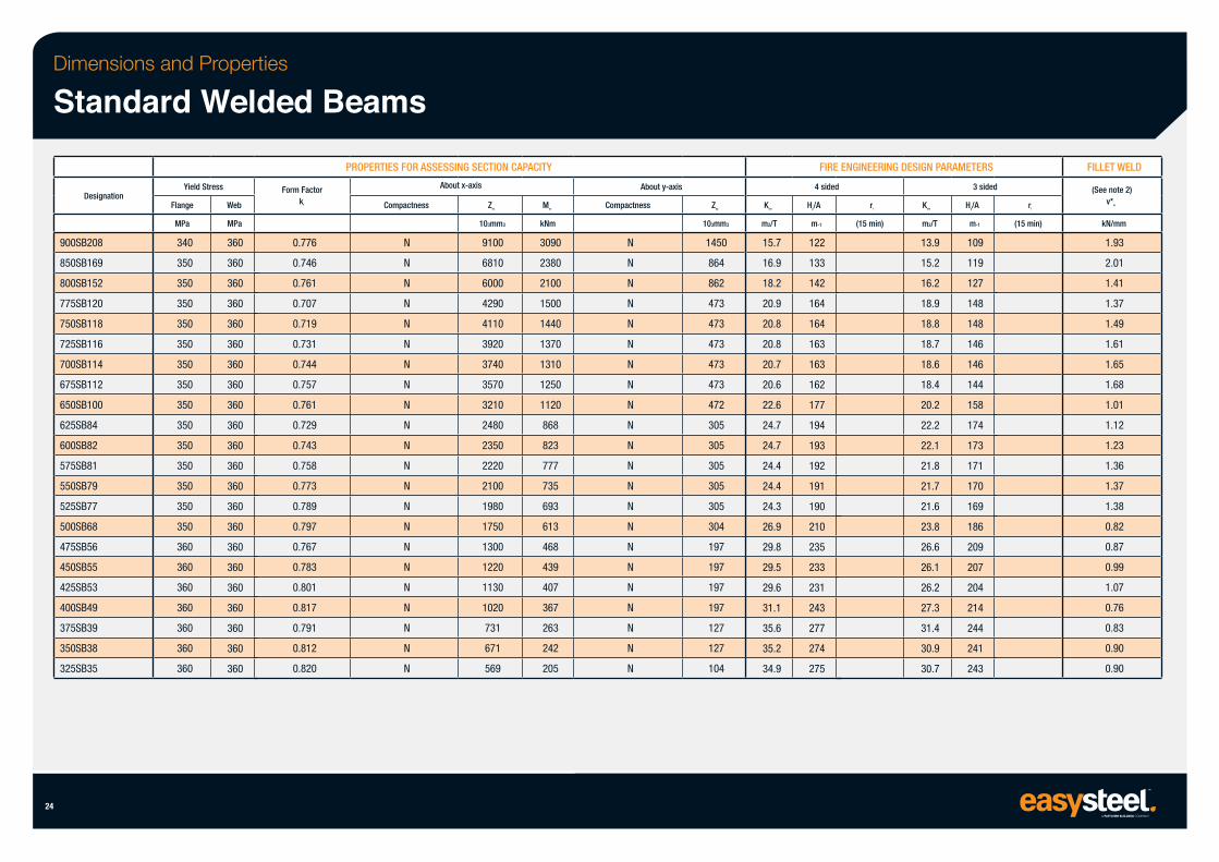
Dimensions and Properties
Standard Welded Beams
Designation
900SB208
850SB169
800SB152
775SB120
750SB118
725SB116
700SB114
675SB112
650SB100
625SB84
600SB82
575SB81
550SB79
525SB77
500SB68
475SB56
450SB55
425SB53
400SB49
375SB39
350SB38
325SB35
24
Yield Stress
Flange
MPa
340
350
350
350
350
350
350
350
350
350
350
350
350
350
350
360
360
360
360
360
360
360
Web
MPa
360
360
360
360
360
360
360
360
360
360
360
360
360
360
360
360
360
360
360
360
360
360
Form Factor kf
0.776
0.746
0.761
0.707
0.719
0.731
0.744
0.757
0.761
0.729
0.743
0.758
0.773
0.789
0.797
0.767
0.783
0.801
0.817
0.791
0.812
0.820
PROPERTIES FOR ASSESSING SECTION CAPACITY
About x-axis
Compactness
N
N
N
N
N
N
N
N
N
N
N
N
N
N
N
N
N
N
N
N
N
N
Zex
103mm3
9100
6810
6000
4290
4110
3920
3740
3570
3210
2480
2350
2220
2100
1980
1750
1300
1220
1130
1020
731
671
569
Msx
kNm
3090
2380
2100
1500
1440
1370
1310
1250
1120
868
823
777
735
693
613
468
439
407
367
263
242
205
About y-axis
Compactness
N
N
N
N
N
N
N
N
N
N
N
N
N
N
N
N
N
N
N
N
N
N
Zey
103mm3
1450
864
862
473
473
473
473
473
472
305
305
305
305
305
304
197
197
197
197
127
127
104
Ksm
m2/T
15.7
16.9
18.2
20.9
20.8
20.8
20.7
20.6
22.6
24.7
24.7
24.4
24.4
24.3
26.9
29.8
29.5
29.6
31.1
35.6
35.2
34.9
FIRE ENGINEERING DESIGN PARAMETERS
4 sided
Hp/A
m-1
122
133
142
164
164
163
163
162
177
194
193
192
191
190
210
235
233
231
243
277
274
275
rf
(15 min)
Ksm
m2/T
13.9
15.2
16.2
18.9
18.8
18.7
18.6
18.4
20.2
22.2
22.1
21.8
21.7
21.6
23.8
26.6
26.1
26.2
27.3
31.4
30.9
30.7
3 sided
Hp/A
m-1
109
119
127
148
148
146
146
144
158
174
173
171
170
169
186
209
207
204
214
244
241
243
rf
(15 min)
FILLET WELD
(See note 2) v*w
kN/mm
1.93
2.01
1.41
1.37
1.49
1.61
1.65
1.68
1.01
1.12
1.23
1.36
1.37
1.38
0.82
0.87
0.99
1.07
0.76
0.83
0.90
0.90
Parallel & Taper Flange Channels
25
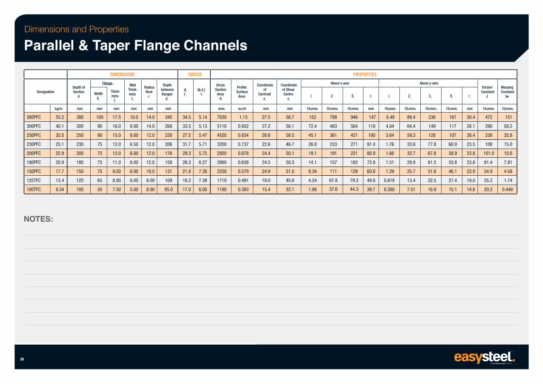
Dimensions and Properties
Parallel & Taper Flange Channels
Designation
380PFC
300PFC
250PFC
230PFC
200PFC
180PFC
150PFC
125TFC
100TFC
kg/m
55.2
40.1
35.5
25.1
22.9
20.9
17.7
13.4
9.34
NOTES:
26
Depth of Section
d
mm
380
300
250
230
200
180
150
125
100
DIMENSIONS
Flange
Width bf
mm
100
90
90
75
75
75
75
65
50
Thick- ness
tf
mm
17.5
16.0
15.0
12.0
12.0
11.0
9.50
8.00
7.50
Web Thick- ness
tw
mm
10.0
8.00
8.00
6.50
6.00
6.00
6.00
6.00
5.00
Radius Root
r
mm
14.0
14.0
12.0
12.0
12.0
12.0
10.0
8.00
8.00
Depth between flanges
d1
mm
345
268
220
206
176
158
131
109
85.0
RATIOS
d1
tw
34.5
33.5
27.5
31.7
29.3
26.3
21.8
18.2
17.0
(bf-tw) tf
5.14
5.13
5.47
5.71
5.75
6.27
7.26
7.38
6.00
Gross Section
Area A
mm2
7030
5110
4520
3200
2920
2660
2250
1710
1190
Profile Surface
Area
m2/m
1.13
0.932
0.834
0.737
0.678
0.638
0.579
0.491
0.383
Coordinate of
Centroid xL
mm
27.5
27.2
28.6
22.6
24.4
24.5
24.9
19.0
15.4
Coordinate of Shear Centre
x0
mm
56.7
56.1
58.5
46.7
50.1
50.3
51.0
40.8
32.1
Ix
106mm4
152
72.4
45.1
26.8
19.1
14.1
8.34
4.24
1.88
About x-axis
Zx
103mm3
798
483
361
233
191
157
111
67.8
37.6
PROPERTIES
Sx
103mm3
946
564
421
271
221
182
129
79.3
44.3
rx
mm
147
119
100
91.4
80.9
72.9
60.8
49.8
39.7
Iy
106mm4
6.48
4.04
3.64
1.76
1.66
1.51
1.29
0.618
0.260
ZyL
103mm3
89.4
64.4
59.3
33.6
32.7
29.9
25.7
13.4
7.51
About y-axis
ZyR
103mm3
236
149
128
77.8
67.8
61.5
51.6
32.5
16.9
Sy
103mm3
161
117
107
60.9
58.9
53.8
46.1
27.4
15.1
ry
mm
30.4
28.1
28.4
23.5
23.8
23.8
23.9
19.0
14.8
Torsion Constant
J
103mm4
472
290
238
108
101.0
81.4
54.9
35.2
20.2
Warping Constant
Iw
109mm6
151
58.2
35.8
15.0
10.6
7.81
4.58
1.74
0.449
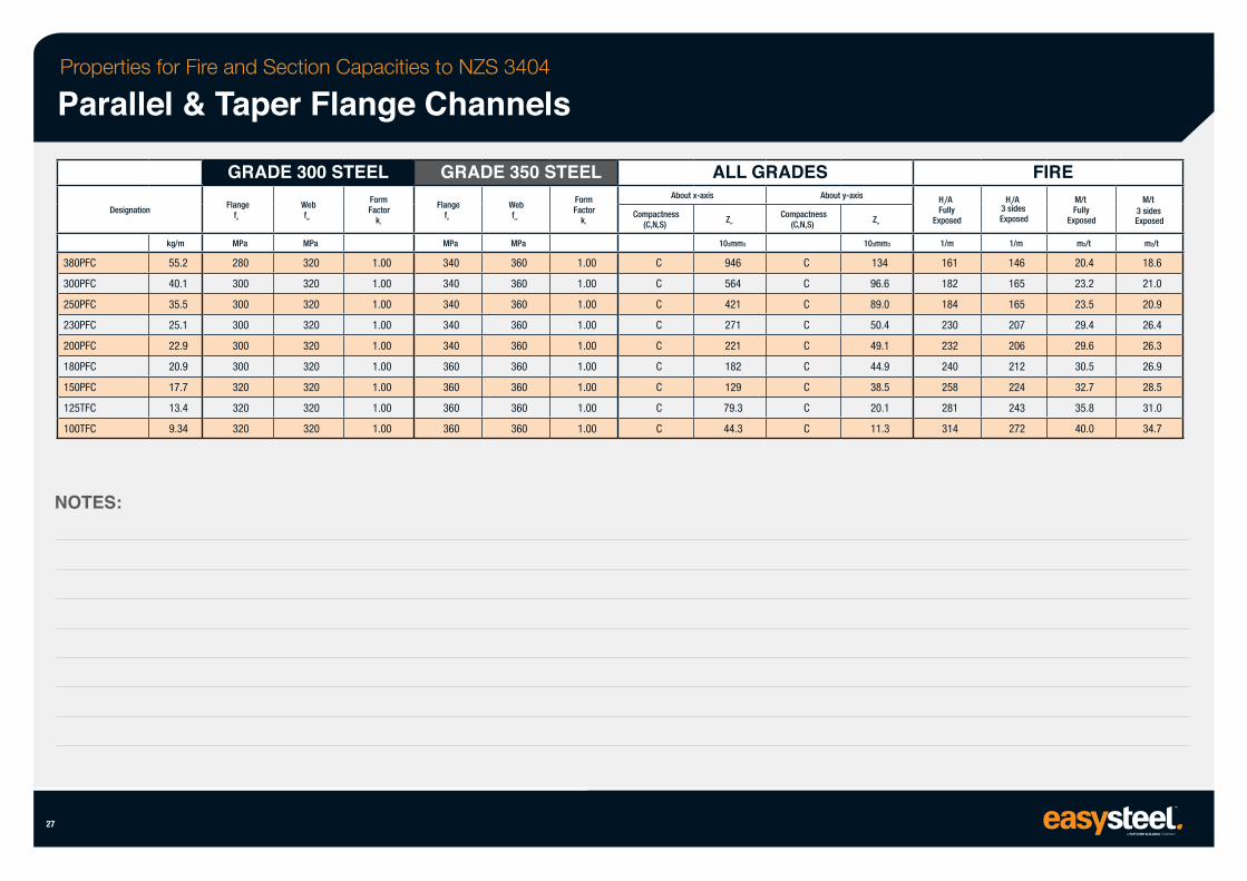
Properties for Fire and Section Capacities to NZS 3404
Parallel & Taper Flange Channels
380PFC
300PFC
250PFC
230PFC
200PFC
180PFC
150PFC
125TFC
100TFC
Designation
NOTES:
27
kg/m
55.2
40.1
35.5
25.1
22.9
20.9
17.7
13.4
9.34
GRADE 300 STEEL Flange
fyf
MPa
280
300
300
300
300
300
320
320
320
Web fyw
MPa
320
320
320
320
320
320
320
320
320
Form Factor
kf
1.00
1.00
1.00
1.00
1.00
1.00
1.00
1.00
1.00
GRADE 350 STEEL Flange
fyf
MPa
340
340
340
340
340
360
360
360
360
Web fyw
MPa
360
360
360
360
360
360
360
360
360
Form Factor
kf
1.00
1.00
1.00
1.00
1.00
1.00
1.00
1.00
1.00
ALL GRADES About x-axis
Compactness (C,N,S)
C
C
C
C
C
C
C
C
C
Zex
103mm3
946
564
421
271
221
182
129
79.3
44.3
About y-axis
Compactness (C,N,S)
C
C
C
C
C
C
C
C
C
Zey
103mm3
134
96.6
89.0
50.4
49.1
44.9
38.5
20.1
11.3
Hp/A Fully
Exposed
1/m
161
182
184
230
232
240
258
281
314
FIRE Hp/A
3 sides Exposed
1/m
146
165
165
207
206
212
224
243
272
M/t Fully
Exposed
m2/t
20.4
23.2
23.5
29.4
29.6
30.5
32.7
35.8
40.0
M/t 3 sides Exposed
m2/t
18.6
21.0
20.9
26.4
26.3
26.9
28.5
31.0
34.7
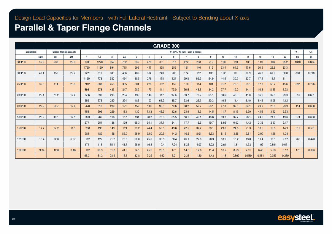
Design Load Capacities for Members - with Full Lateral Restraint - Subject to Bending about X-axis
Parallel & Taper Flange Channels
Designation
380PFC
300PFC
28
250PFC
230PFC
200PFC
180PFC
150PFC
125TFC
100TFC
kg/m
55.2
40.1
35.5
25.1
22.9
20.9
17.7
13.4
9.34
Section Moment Capacity
øMsx
238
152
114
73.2
59.7
49.1
37.2
22.8
12.8
øMsy
29.0
22.2
23.9
12.2
12.6
12.1
11.1
6.57
3.46
1
1900
1790
1220
1160
912
866
586
559
478
458
393
377
298
284
182
174
102
96.3
1.5
1270
1190
811
773
608
578
390
373
318
306
262
251
198
189
122
116
68.3
51.3
2
952
894
608
580
456
433
293
280
239
229
196
188
149
128
91.2
65.1
51.2
28.9
2.5
762
715
486
464
365
347
234
224
191
183
157
139
119
82.0
73.0
41.7
41.0
18.5
3
635
596
405
386
304
289
195
183
159
130
131
96.3
99.2
56.9
60.8
28.9
34.1
12.8
4
476
447
304
278
228
173
146
103
119
73.3
98.2
54.1
74.4
32.0
45.6
16.3
25.6
7.22
GRADE 300
5
381
358
243
178
182
111
117
65.9
95.5
46.9
78.6
34.7
59.5
20.5
36.5
10.4
20.5
4.62
WLC1 (kN) / Ws (kN) - Span in metres
6
317
259
203
124
152
77.0
97.6
45.7
79.6
32.6
65.5
24.1
49.6
14.2
30.4
7.24
17.1
3.21
7
272
191
174
90.8
130
56.5
83.7
33.6
68.2
23.9
56.1
17.7
42.5
10.5
26.1
5.32
14.6
2.36
8
238
146
152
69.5
114
43.3
73.2
25.7
59.7
18.3
49.1
13.5
37.2
8.01
22.8
4.07
12.8
1.80
9
212
115
135
54.9
101
34.2
65.1
20.3
53.1
14.5
43.6
10.7
33.1
6.33
20.3
3.22
11.4
1.43
10
190
93.4
122
44.5
91.2
27.7
58.6
16.5
47.8
11.7
39.3
8.66
29.8
5.12
18.2
2.61
10.2
1.16
12
159
64.9
101
30.9
76.0
19.2
48.8
11.4
39.8
8.15
32.7
6.02
24.8
3.56
15.2
1.81
8.53
0.802
14
136
47.6
86.9
22.7
65.1
14.1
41.8
8.40
34.1
5.99
28.1
4.42
21.3
2.61
13.0
1.33
7.31
0.589
16
119
36.5
76.0
17.4
57.0
10.8
36.6
6.43
29.9
4.58
24.6
3.38
18.6
2.00
11.4
1.02
6.40
0.451
18
106
28.8
67.6
13.7
50.7
8.55
32.5
5.08
26.5
3.62
21.8
2.67
16.5
1.58
10.1
0.804
5.69
0.357
20
95.2
23.3
60.8
11.1
45.6
6.93
29.3
4.12
23.9
2.93
19.6
2.17
14.9
1.28
9.12
0.651
5.12
0.289
WLC2
kN
1310
830
692
516
414
374
312
260
173
FLR
m
0.804
0.718
0.726
0.601
0.608
0.608
0.591
0.470
0.366
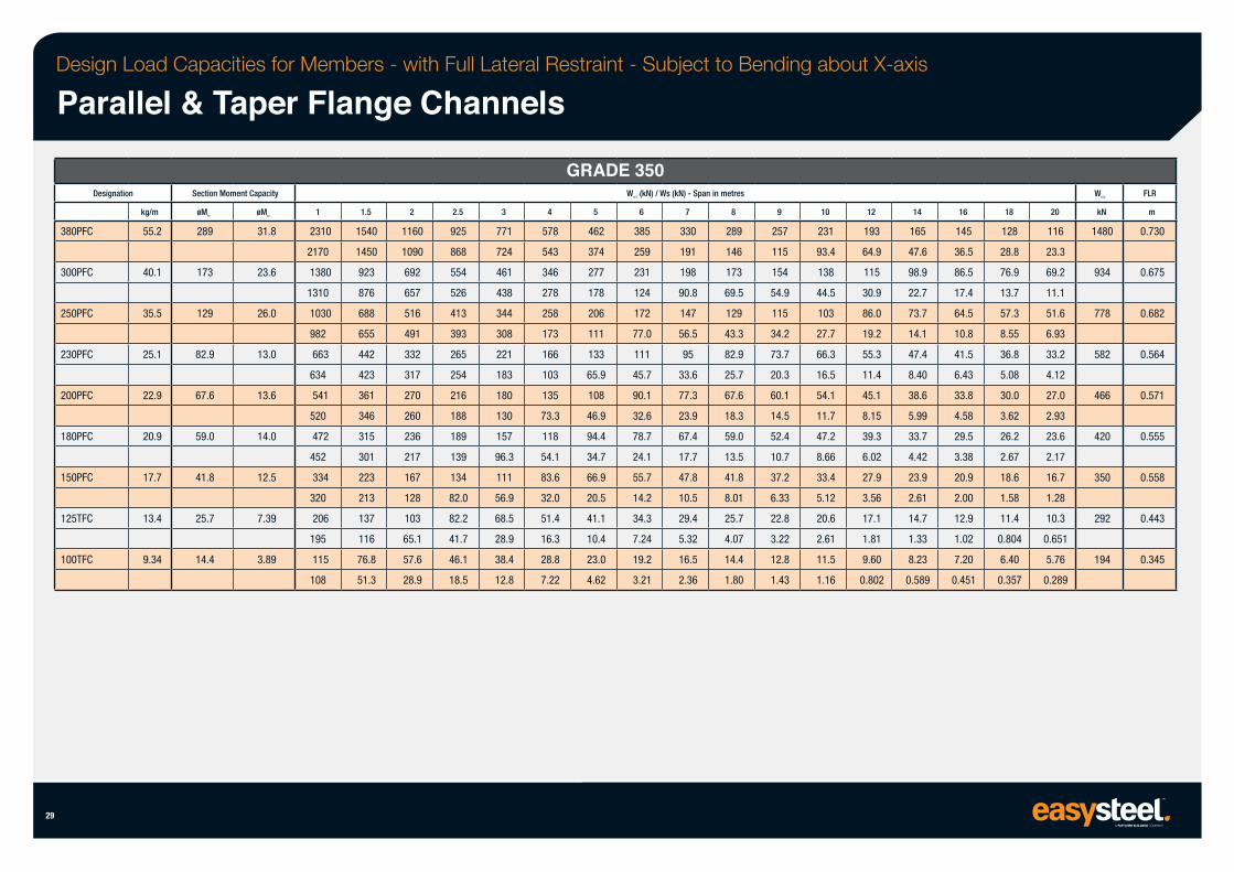
Design Load Capacities for Members - with Full Lateral Restraint - Subject to Bending about X-axis
Parallel & Taper Flange Channels
Designation
380PFC
300PFC
250PFC
230PFC
200PFC
180PFC
150PFC
125TFC
100TFC
29
kg/m
55.2
40.1
35.5
25.1
22.9
20.9
17.7
13.4
9.34
Section Moment Capacity
øMsx
289
173
129
82.9
67.6
59.0
41.8
25.7
14.4
øMsy
31.8
23.6
26.0
13.0
13.6
14.0
12.5
7.39
3.89
1
2310
2170
1380
1310
1030
982
663
634
541
520
472
452
334
320
206
195
115
108
1.5
1540
1450
923
876
688
655
442
423
361
346
315
301
223
213
137
116
76.8
51.3
2
1160
1090
692
657
516
491
332
317
270
260
236
217
167
128
103
65.1
57.6
28.9
2.5
925
868
554
526
413
393
265
254
216
188
189
139
134
82.0
82.2
41.7
46.1
18.5
3
771
724
461
438
344
308
221
183
180
130
157
96.3
111
56.9
68.5
28.9
38.4
12.8
4
578
543
346
278
258
173
166
103
135
73.3
118
54.1
83.6
32.0
51.4
16.3
28.8
7.22
GRADE 350
5
462
374
277
178
206
111
133
65.9
108
46.9
94.4
34.7
66.9
20.5
41.1
10.4
23.0
4.62
WLC1 (kN) / Ws (kN) - Span in metres
6
385
259
231
124
172
77.0
111
45.7
90.1
32.6
78.7
24.1
55.7
14.2
34.3
7.24
19.2
3.21
7
330
191
198
90.8
147
56.5
95
33.6
77.3
23.9
67.4
17.7
47.8
10.5
29.4
5.32
16.5
2.36
8
289
146
173
69.5
129
43.3
82.9
25.7
67.6
18.3
59.0
13.5
41.8
8.01
25.7
4.07
14.4
1.80
9
257
115
154
54.9
115
34.2
73.7
20.3
60.1
14.5
52.4
10.7
37.2
6.33
22.8
3.22
12.8
1.43
10
231
93.4
138
44.5
103
27.7
66.3
16.5
54.1
11.7
47.2
8.66
33.4
5.12
20.6
2.61
11.5
1.16
12
193
64.9
115
30.9
86.0
19.2
55.3
11.4
45.1
8.15
39.3
6.02
27.9
3.56
17.1
1.81
9.60
0.802
14
165
47.6
98.9
22.7
73.7
14.1
47.4
8.40
38.6
5.99
33.7
4.42
23.9
2.61
14.7
1.33
8.23
0.589
16
145
36.5
86.5
17.4
64.5
10.8
41.5
6.43
33.8
4.58
29.5
3.38
20.9
2.00
12.9
1.02
7.20
0.451
18
128
28.8
76.9
13.7
57.3
8.55
36.8
5.08
30.0
3.62
26.2
2.67
18.6
1.58
11.4
0.804
6.40
0.357
20
116
23.3
69.2
11.1
51.6
6.93
33.2
4.12
27.0
2.93
23.6
2.17
16.7
1.28
10.3
0.651
5.76
0.289
WLC2
kN
1480
934
778
582
466
420
350
292
194
FLR
m
0.730
0.675
0.682
0.564
0.571
0.555
0.558
0.443
0.345
Hollow Sections
30
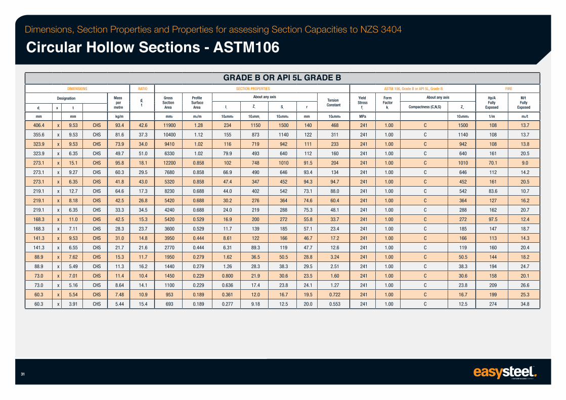
Dimensions, Section Properties and Properties for assessing Section Capacities to NZS 3404
Circular Hollow Sections - ASTM106
31
do
mm
406.4
355.6
323.9
323.9
273.1
273.1
273.1
219.1
219.1
219.1
168.3
168.3
141.3
141.3
88.9
88.9
73.0
73.0
60.3
60.3
DIMENSIONS
Designation
x
x
x
x
x
x
x
x
x
x
x
x
x
x
x
x
x
x
x
x
x
t
mm
9.53
9.53
9.53
6.35
15.1
9.27
6.35
12.7
8.18
6.35
11.0
7.11
9.53
6.55
7.62
5.49
7.01
5.16
5.54
3.91
CHS
CHS
CHS
CHS
CHS
CHS
CHS
CHS
CHS
CHS
CHS
CHS
CHS
CHS
CHS
CHS
CHS
CHS
CHS
CHS
Mass per
metre
kg/m
93.4
81.6
73.9
49.7
95.8
60.3
41.8
64.6
42.5
33.3
42.5
28.3
31.0
21.7
15.3
11.3
11.4
8.64
7.48
5.44
RATIO
do
t
42.6
37.3
34.0
51.0
18.1
29.5
43.0
17.3
26.8
34.5
15.3
23.7
14.8
21.6
11.7
16.2
10.4
14.1
10.9
15.4
Gross Section
Area
mm2
11900
10400
9410
6330
12200
7680
5320
8230
5420
4240
5420
3600
3950
2770
1950
1440
1450
1100
953
693
Profile Surface
Area
m2/m
1.28
1.12
1.02
1.02
0.858
0.858
0.858
0.688
0.688
0.688
0.529
0.529
0.444
0.444
0.279
0.279
0.229
0.229
0.189
0.189
GRADE B OR API 5L GRADE B
Ix
106mm4
234
155
116
79.9
102
66.9
47.4
44.0
30.2
24.0
16.9
11.7
8.61
6.31
1.62
1.26
0.800
0.636
0.361
0.277
SECTION PROPERTIES
About any axis
Zx
103mm3
1150
873
719
493
748
490
347
402
276
219
200
139
122
89.3
36.5
28.3
21.9
17.4
12.0
9.18
Sx
103mm3
1500
1140
942
640
1010
646
452
542
364
288
272
185
166
119
50.5
38.3
30.6
23.8
16.7
12.5
r
mm
140
122
111
112
91.5
93.4
94.3
73.1
74.6
75.3
55.8
57.1
46.7
47.7
28.8
29.5
23.5
24.1
19.5
20.0
Torsion Constant
106mm4
468
311
233
160
204
134
94.7
88.0
60.4
48.1
33.7
23.4
17.2
12.6
3.24
2.51
1.60
1.27
0.722
0.553
Yield Stress
fy
MPa
241
241
241
241
241
241
241
241
241
241
241
241
241
241
241
241
241
241
241
241
ASTM 106, Grade B or API 5L, Grade B
Form Factor
kf
1.00
1.00
1.00
1.00
1.00
1.00
1.00
1.00
1.00
1.00
1.00
1.00
1.00
1.00
1.00
1.00
1.00
1.00
1.00
1.00
About any axis
Compactness (C,N,S)
C
C
C
C
C
C
C
C
C
C
C
C
C
C
C
C
C
C
C
C
Zex
103mm3
1500
1140
942
640
1010
646
452
542
364
288
272
185
166
119
50.5
38.3
30.6
23.8
16.7
12.5
Hp/A Fully
Exposed
1/m
108
108
108
161
70.1
112
161
83.6
127
162
97.5
147
113
160
144
194
158
209
199
274
FIRE
M/t Fully
Exposed
m2/t
13.7
13.7
13.8
20.5
9.0
14.2
20.5
10.7
16.2
20.7
12.4
18.7
14.3
20.4
18.2
24.7
20.1
26.6
25.3
34.8
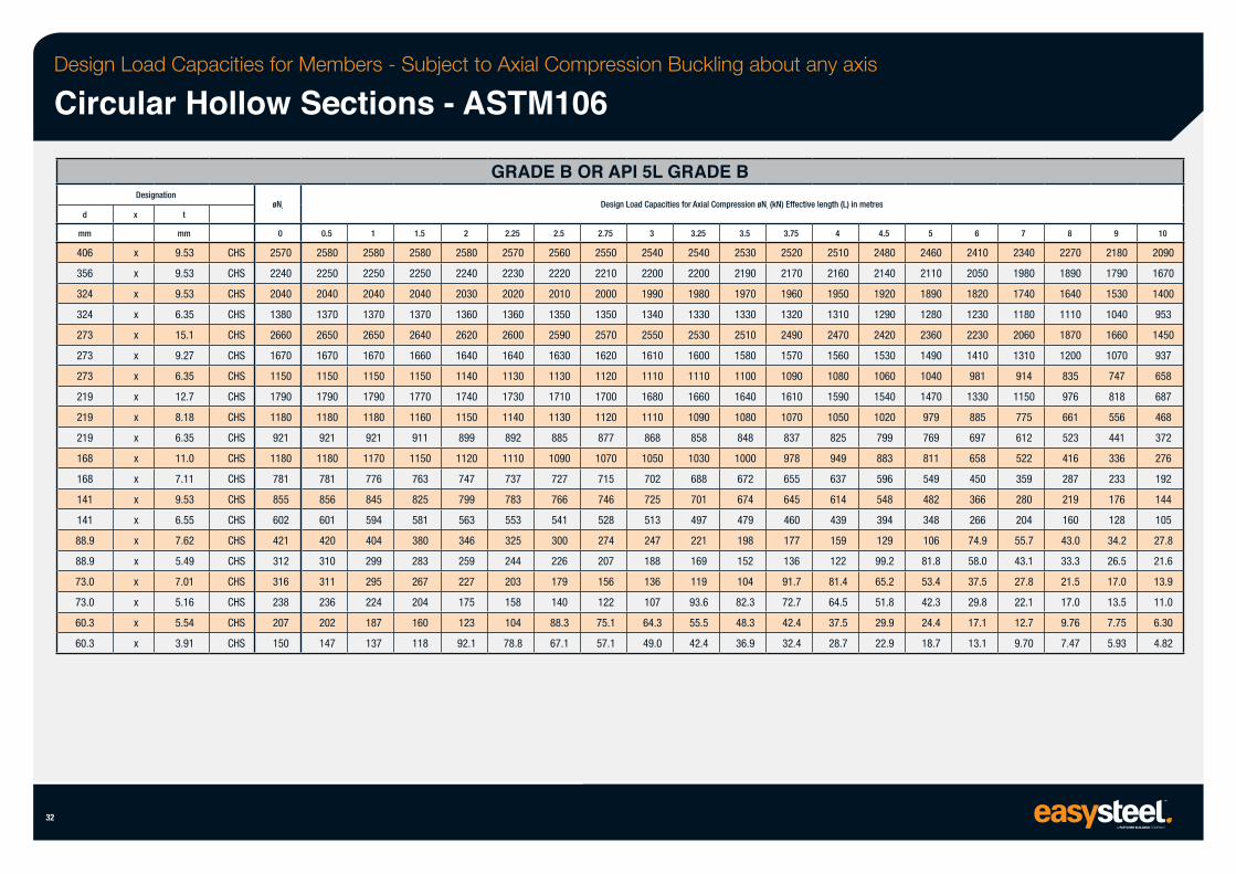
Design Load Capacities for Members - Subject to Axial Compression Buckling about any axis
Circular Hollow Sections - ASTM106
32
d
mm
406
356
324
324
273
273
273
219
219
219
168
168
141
141
88.9
88.9
73.0
73.0
60.3
60.3
Designation
x
x
x
x
x
x
x
x
x
x
x
x
x
x
x
x
x
x
x
x
x
t
mm
9.53
9.53
9.53
6.35
15.1
9.27
6.35
12.7
8.18
6.35
11.0
7.11
9.53
6.55
7.62
5.49
7.01
5.16
5.54
3.91
CHS
CHS
CHS
CHS
CHS
CHS
CHS
CHS
CHS
CHS
CHS
CHS
CHS
CHS
CHS
CHS
CHS
CHS
CHS
CHS
øNs
0
2570
2240
2040
1380
2660
1670
1150
1790
1180
921
1180
781
855
602
421
312
316
238
207
150
0.5
2580
2250
2040
1370
2650
1670
1150
1790
1180
921
1180
781
856
601
420
310
311
236
202
147
1
2580
2250
2040
1370
2650
1670
1150
1790
1180
921
1170
776
845
594
404
299
295
224
187
137
1.5
2580
2250
2040
1370
2640
1660
1150
1770
1160
911
1150
763
825
581
380
283
267
204
160
118
2
2580
2240
2030
1360
2620
1640
1140
1740
1150
899
1120
747
799
563
346
259
227
175
123
92.1
GRADE B OR API 5L GRADE B
2.25
2570
2230
2020
1360
2600
1640
1130
1730
1140
892
1110
737
783
553
325
244
203
158
104
78.8
2.5
2560
2220
2010
1350
2590
1630
1130
1710
1130
885
1090
727
766
541
300
226
179
140
88.3
67.1
Design Load Capacities for Axial Compression øNc (kN) Effective length (L) in metres
2.75
2550
2210
2000
1350
2570
1620
1120
1700
1120
877
1070
715
746
528
274
207
156
122
75.1
57.1
3
2540
2200
1990
1340
2550
1610
1110
1680
1110
868
1050
702
725
513
247
188
136
107
64.3
49.0
3.25
2540
2200
1980
1330
2530
1600
1110
1660
1090
858
1030
688
701
497
221
169
119
93.6
55.5
42.4
3.5
2530
2190
1970
1330
2510
1580
1100
1640
1080
848
1000
672
674
479
198
152
104
82.3
48.3
36.9
3.75
2520
2170
1960
1320
2490
1570
1090
1610
1070
837
978
655
645
460
177
136
91.7
72.7
42.4
32.4
4
2510
2160
1950
1310
2470
1560
1080
1590
1050
825
949
637
614
439
159
122
81.4
64.5
37.5
28.7
4.5
2480
2140
1920
1290
2420
1530
1060
1540
1020
799
883
596
548
394
129
99.2
65.2
51.8
29.9
22.9
5
2460
2110
1890
1280
2360
1490
1040
1470
979
769
811
549
482
348
106
81.8
53.4
42.3
24.4
18.7
6
2410
2050
1820
1230
2230
1410
981
1330
885
697
658
450
366
266
74.9
58.0
37.5
29.8
17.1
13.1
7
2340
1980
1740
1180
2060
1310
914
1150
775
612
522
359
280
204
55.7
43.1
27.8
22.1
12.7
9.70
8
2270
1890
1640
1110
1870
1200
835
976
661
523
416
287
219
160
43.0
33.3
21.5
17.0
9.76
7.47
9
2180
1790
1530
1040
1660
1070
747
818
556
441
336
233
176
128
34.2
26.5
17.0
13.5
7.75
5.93
10
2090
1670
1400
953
1450
937
658
687
468
372
276
192
144
105
27.8
21.6
13.9
11.0
6.30
4.82
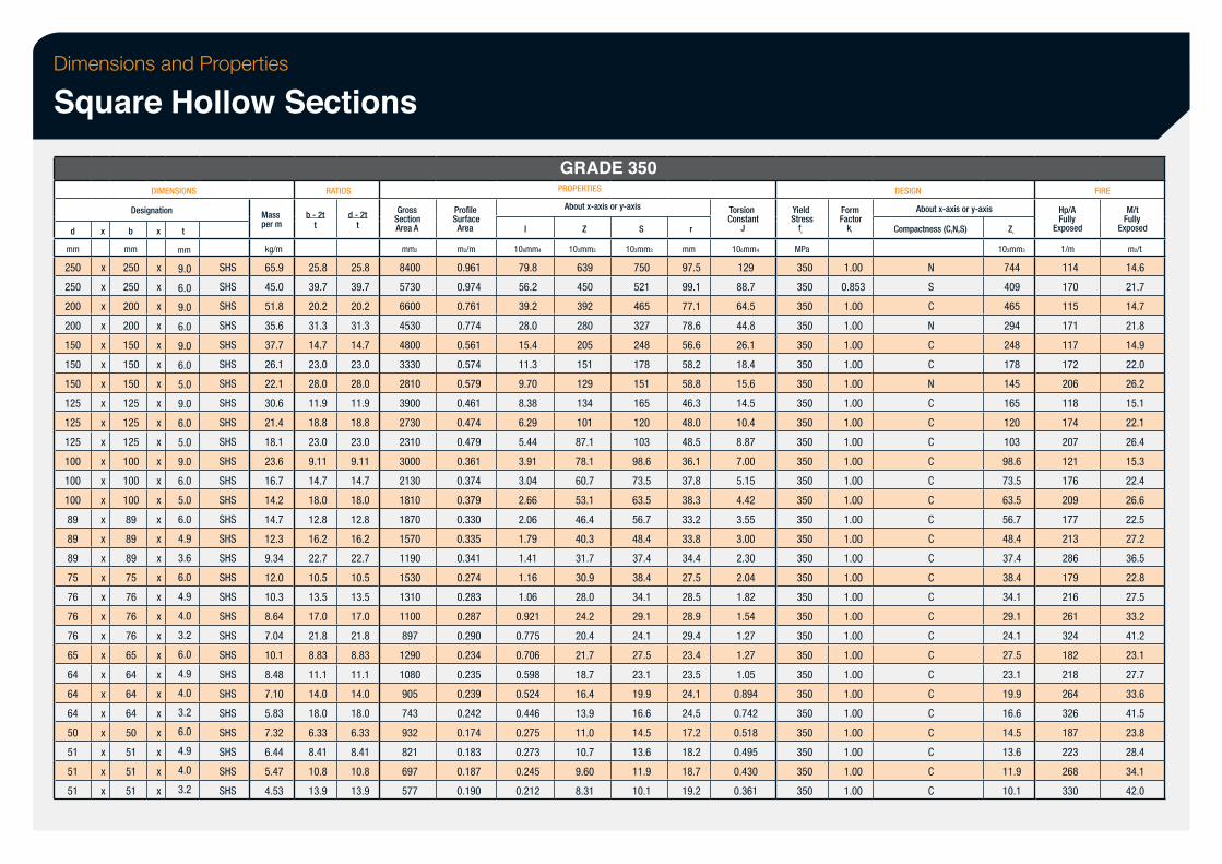
Dimensions and Properties
Square Hollow Sections
d
mm
250
250
200
200
150
150
150
125
125
125
100
100
100
89
89
89
75
76
76
76
65
64
64
64
50
51
51
51
x
x
x
x
x
x
x
x
x
x
x
x
x
x
x
x
x
x
x
x
x
x
x
x
x
x
x
x
x
DIMENSIONS
Designation
b
mm
250
250
200
200
150
150
150
125
125
125
100
100
100
89
89
89
75
76
76
76
65
64
64
64
50
51
51
51
x
x
x
x
x
x
x
x
x
x
x
x
x
x
x
x
x
x
x
x
x
x
x
x
x
x
x
x
x
t
mm
9.0
6.0
9.0
6.0
9.0
6.0
5.0
9.0
6.0
5.0
9.0
6.0
5.0
6.0
4.9
3.6
6.0
4.9
4.0
3.2
6.0
4.9
4.0
3.2
6.0
4.9
4.0
3.2
SHS
SHS
SHS
SHS
SHS
SHS
SHS
SHS
SHS
SHS
SHS
SHS
SHS
SHS
SHS
SHS
SHS
SHS
SHS
SHS
SHS
SHS
SHS
SHS
SHS
SHS
SHS
SHS
Mass per m
kg/m
65.9
45.0
51.8
35.6
37.7
26.1
22.1
30.6
21.4
18.1
23.6
16.7
14.2
14.7
12.3
9.34
12.0
10.3
8.64
7.04
10.1
8.48
7.10
5.83
7.32
6.44
5.47
4.53
RATIOS
b - 2t t
25.8
39.7
20.2
31.3
14.7
23.0
28.0
11.9
18.8
23.0
9.11
14.7
18.0
12.8
16.2
22.7
10.5
13.5
17.0
21.8
8.83
11.1
14.0
18.0
6.33
8.41
10.8
13.9
d - 2t t
25.8
39.7
20.2
31.3
14.7
23.0
28.0
11.9
18.8
23.0
9.11
14.7
18.0
12.8
16.2
22.7
10.5
13.5
17.0
21.8
8.83
11.1
14.0
18.0
6.33
8.41
10.8
13.9
Gross Section Area A
mm2
8400
5730
6600
4530
4800
3330
2810
3900
2730
2310
3000
2130
1810
1870
1570
1190
1530
1310
1100
897
1290
1080
905
743
932
821
697
577
Profile Surface Area
m2/m
0.961
0.974
0.761
0.774
0.561
0.574
0.579
0.461
0.474
0.479
0.361
0.374
0.379
0.330
0.335
0.341
0.274
0.283
0.287
0.290
0.234
0.235
0.239
0.242
0.174
0.183
0.187
0.190
I
106mm4
79.8
56.2
39.2
28.0
15.4
11.3
9.70
8.38
6.29
5.44
3.91
3.04
2.66
2.06
1.79
1.41
1.16
1.06
0.921
0.775
0.706
0.598
0.524
0.446
0.275
0.273
0.245
0.212
GRADE 350 PROPERTIES
About x-axis or y-axis
Z
103mm3
639
450
392
280
205
151
129
134
101
87.1
78.1
60.7
53.1
46.4
40.3
31.7
30.9
28.0
24.2
20.4
21.7
18.7
16.4
13.9
11.0
10.7
9.60
8.31
S
103mm3
750
521
465
327
248
178
151
165
120
103
98.6
73.5
63.5
56.7
48.4
37.4
38.4
34.1
29.1
24.1
27.5
23.1
19.9
16.6
14.5
13.6
11.9
10.1
r
mm
97.5
99.1
77.1
78.6
56.6
58.2
58.8
46.3
48.0
48.5
36.1
37.8
38.3
33.2
33.8
34.4
27.5
28.5
28.9
29.4
23.4
23.5
24.1
24.5
17.2
18.2
18.7
19.2
Torsion Constant
J
106mm4
129
88.7
64.5
44.8
26.1
18.4
15.6
14.5
10.4
8.87
7.00
5.15
4.42
3.55
3.00
2.30
2.04
1.82
1.54
1.27
1.27
1.05
0.894
0.742
0.518
0.495
0.430
0.361
Yield Stress
fy
MPa
350
350
350
350
350
350
350
350
350
350
350
350
350
350
350
350
350
350
350
350
350
350
350
350
350
350
350
350
Form Factor
kf
1.00
0.853
1.00
1.00
1.00
1.00
1.00
1.00
1.00
1.00
1.00
1.00
1.00
1.00
1.00
1.00
1.00
1.00
1.00
1.00
1.00
1.00
1.00
1.00
1.00
1.00
1.00
1.00
DESIGN
About x-axis or y-axis
Compactness (C,N,S)
N
S
C
N
C
C
N
C
C
C
C
C
C
C
C
C
C
C
C
C
C
C
C
C
C
C
C
C
Ze
103mm3
744
409
465
294
248
178
145
165
120
103
98.6
73.5
63.5
56.7
48.4
37.4
38.4
34.1
29.1
24.1
27.5
23.1
19.9
16.6
14.5
13.6
11.9
10.1
Hp/A Fully
Exposed
1/m
114
170
115
171
117
172
206
118
174
207
121
176
209
177
213
286
179
216
261
324
182
218
264
326
187
223
268
330
FIRE
M/t Fully
Exposed
m2/t
14.6
21.7
14.7
21.8
14.9
22.0
26.2
15.1
22.1
26.4
15.3
22.4
26.6
22.5
27.2
36.5
22.8
27.5
33.2
41.2
23.1
27.7
33.6
41.5
23.8
28.4
34.1
42.0
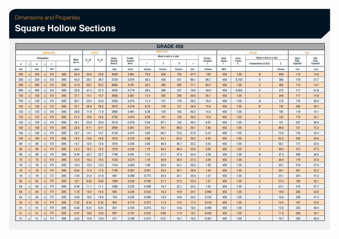
Dimensions and Properties
Square Hollow Sections
d
mm
250
250
200
200
150
150
150
125
125
125
100
100
100
89
89
89
75
76
76
76
65
64
64
64
50
51
51
51
x
x
x
x
x
x
x
x
x
x
x
x
x
x
x
x
x
x
x
x
x
x
x
x
x
x
x
x
x
DIMENSIONS
Designation
b
mm
250
250
200
200
150
150
150
125
125
125
100
100
100
89
89
89
75
76
76
76
65
64
64
64
50
51
51
51
x
x
x
x
x
x
x
x
x
x
x
x
x
x
x
x
x
x
x
x
x
x
x
x
x
x
x
x
x
t
mm
9.0
6.0
9.0
6.0
9.0
6.0
5.0
9.0
6.0
5.0
9.0
6.0
5.0
6.0
4.9
3.6
6.0
4.9
4.0
3.2
6.0
4.9
4.0
3.2
6.0
4.9
4.0
3.2
SHS
SHS
SHS
SHS
SHS
SHS
SHS
SHS
SHS
SHS
SHS
SHS
SHS
SHS
SHS
SHS
SHS
SHS
SHS
SHS
SHS
SHS
SHS
SHS
SHS
SHS
SHS
SHS
Mass per m
kg/m
65.9
45.0
51.8
35.6
37.7
26.1
22.1
30.6
21.4
18.1
23.6
16.7
14.2
14.7
12.3
9.34
12.0
10.3
8.64
7.04
10.1
8.48
7.10
5.83
7.32
6.44
5.47
4.53
RATIOS
b - 2t t
25.8
39.7
20.2
31.3
14.7
23.0
28.0
11.9
18.8
23.0
9.11
14.7
18.0
12.8
16.2
22.7
10.5
13.5
17.0
21.8
8.83
11.1
14.0
18.0
6.33
8.41
10.8
13.9
d - 2t t
25.8
39.7
20.2
31.3
14.7
23.0
28.0
11.9
18.8
23.0
9.11
14.7
18.0
12.8
16.2
22.7
10.5
13.5
17.0
21.8
8.83
11.1
14.0
18.0
6.33
8.41
10.8
13.9
Gross Section Area A
mm2
8400
5730
6600
4530
4800
3330
2810
3900
2730
2310
3000
2130
1810
1870
1570
1190
1530
1310
1100
897
1290
1080
905
743
932
821
697
577
Profile Surface Area
m2/m
0.961
0.974
0.761
0.774
0.561
0.574
0.579
0.461
0.474
0.479
0.361
0.374
0.379
0.330
0.335
0.341
0.274
0.283
0.287
0.290
0.234
0.235
0.239
0.242
0.174
0.183
0.187
0.190
I
106mm4
79.8
56.2
39.2
28.0
15.4
11.3
9.70
8.38
6.29
5.44
3.91
3.04
2.66
2.06
1.79
1.41
1.16
1.06
0.921
0.775
0.706
0.598
0.524
0.446
0.275
0.273
0.245
0.212
GRADE 450 PROPERTIES
About x-axis or y-axis
Z
103mm3
639
450
392
280
205
151
129
134
101
87.1
78.1
60.7
53.1
46.4
40.3
31.7
30.9
28.0
24.2
20.4
21.7
18.7
16.4
13.9
11.0
10.7
9.60
8.31
S
103mm3
750
521
465
327
248
178
151
165
120
103
98.6
73.5
63.5
56.7
48.4
37.4
38.4
34.1
29.1
24.1
27.5
23.1
19.9
16.6
14.5
13.6
11.9
10.1
r
mm
97.5
99.1
77.1
78.6
56.6
58.2
58.8
46.3
48.0
48.5
36.1
37.8
38.3
33.2
33.8
34.4
27.5
28.5
28.9
29.4
23.4
23.5
24.1
24.5
17.2
18.2
18.7
19.2
Torsion Constant
J
106mm4
129
88.7
64.5
44.8
26.1
18.4
15.6
14.5
10.4
8.87
7.00
5.15
4.42
3.55
3.00
2.30
2.04
1.82
1.54
1.27
1.27
1.05
0.894
0.742
0.518
0.495
0.430
0.361
Yield Stress
fy
MPa
450
450
450
450
450
450
450
450
450
450
450
450
450
450
450
450
450
450
450
450
450
450
450
450
450
450
450
450
Form Factor
kf
1.00
0.752
1.00
0.952
1.00
1.00
1.00
1.00
1.00
1.00
1.00
1.00
1.00
1.00
1.00
1.00
1.00
1.00
1.00
1.00
1.00
1.00
1.00
1.00
1.00
1.00
1.00
1.00
DESIGN
About x-axis or y-axis
Compactness (C,N,S)
N
S
C
S
C
N
N
C
C
N
C
C
C
C
C
N
C
C
C
C
C
C
C
C
C
C
C
C
Ze
103mm3
699
380
465
272
248
175
135
165
120
101
98.6
73.5
63.5
56.7
48.4
37.2
38.4
34.1
29.1
24.1
27.5
23.1
19.9
16.6
14.5
13.6
11.9
10.1
Hp/A Fully
Exposed
1/m
114
170
115
171
117
172
206
118
174
207
121
176
209
177
213
286
179
216
261
324
182
218
264
326
187
223
268
330
FIRE
M/t Fully
Exposed
m2/t
14.6
21.7
14.7
21.8
14.9
22.0
26.2
15.1
22.1
26.4
15.3
22.4
26.6
22.5
27.2
36.5
22.8
27.5
33.2
41.2
23.1
27.7
33.6
41.5
23.8
28.4
34.1
42.0
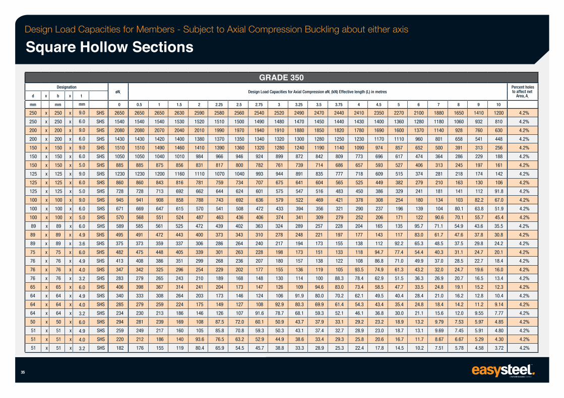
Design Load Capacities for Members - Subject to Axial Compression Buckling about either axis
Square Hollow Sections
35
d
mm
250
250
200
200
150
150
150
125
125
125
100
100
100
89
89
89
75
76
76
76
65
64
64
64
50
51
51
51
x
x
x
x
x
x
x
x
x
x
x
x
x
x
x
x
x
x
x
x
x
x
x
x
x
x
x
x
x
Designation
b
mm
250
250
200
200
150
150
150
125
125
125
100
100
100
89
89
89
75
76
76
76
65
64
64
64
50
51
51
51
x
x
x
x
x
x
x
x
x
x
x
x
x
x
x
x
x
x
x
x
x
x
x
x
x
x
x
x
x
t
mm
9.0
6.0
9.0
6.0
9.0
6.0
5.0
9.0
6.0
5.0
9.0
6.0
5.0
6.0
4.9
3.6
6.0
4.9
4.0
3.2
6.0
4.9
4.0
3.2
6.0
4.9
4.0
3.2
SHS
SHS
SHS
SHS
SHS
SHS
SHS
SHS
SHS
SHS
SHS
SHS
SHS
SHS
SHS
SHS
SHS
SHS
SHS
SHS
SHS
SHS
SHS
SHS
SHS
SHS
SHS
SHS
øNs
0
2650
1540
2080
1430
1510
1050
885
1230
860
728
945
671
570
589
495
375
482
413
347
283
406
340
285
234
294
259
220
182
0.5
2650
1540
2080
1430
1510
1050
885
1230
860
728
941
669
568
585
491
373
475
408
342
279
398
333
279
230
281
249
212
176
1
2650
1540
2070
1420
1490
1040
875
1200
843
713
908
647
551
561
472
359
448
386
325
265
367
308
259
213
239
217
186
155
1.5
2630
1530
2040
1400
1460
1010
856
1160
816
692
858
615
524
525
443
337
405
351
296
243
314
264
224
186
169
160
140
119
2
2590
1520
2010
1380
1410
984
831
1110
781
662
788
570
487
472
400
306
339
299
254
210
241
203
175
146
108
105
93.6
80.4
2.25
2580
1510
1990
1370
1390
966
817
1070
759
644
743
541
463
439
373
286
301
268
229
189
204
173
149
126
87.5
85.8
76.5
65.9
2.5
2560
1500
1970
1350
1360
946
800
1040
734
624
692
508
436
402
343
264
263
236
202
168
173
146
127
107
72.0
70.8
63.2
54.5
GRADE 350 Design Load Capacities for Axial Compression øNc (kN) Effective length (L) in metres
2.75
2540
1490
1940
1340
1320
924
782
993
707
601
636
472
406
363
310
240
228
207
177
148
147
124
108
91.6
60.1
59.3
52.9
45.7
3
2520
1480
1910
1320
1280
899
761
944
675
575
579
433
374
324
278
217
198
180
155
130
126
106
92.9
78.7
50.9
50.3
44.9
38.8
3.25
2490
1470
1880
1300
1240
872
739
891
641
547
522
394
341
289
248
194
173
157
136
114
109
91.9
80.3
68.1
43.7
43.1
38.6
33.3
3.5
2470
1450
1850
1280
1190
842
714
835
604
516
469
356
309
257
221
173
151
138
119
100
94.6
80.0
69.9
59.3
37.9
37.4
33.4
28.9
3.75
2440
1440
1820
1250
1140
809
686
777
565
483
421
321
279
228
197
155
133
122
105
88.3
83.0
70.2
61.4
52.1
33.1
32.7
29.3
25.3
4
2410
1430
1780
1230
1090
773
657
718
525
450
378
290
252
204
177
138
118
108
93.5
78.4
73.4
62.1
54.3
46.1
29.2
28.9
25.8
22.4
4.5
2350
1400
1690
1170
974
696
593
609
449
386
308
237
206
165
143
112
94.7
86.8
74.9
62.9
58.5
49.5
43.4
36.8
23.2
23.0
20.6
17.8
5
2270
1360
1600
1110
857
617
527
515
382
329
254
196
171
135
117
92.2
77.4
71.0
61.3
51.5
47.7
40.4
35.4
30.0
18.9
18.7
16.7
14.5
6
2100
1280
1370
960
652
474
406
374
279
241
180
139
122
95.7
83.0
65.3
54.4
49.9
43.2
36.3
33.5
28.4
24.8
21.1
13.2
13.1
11.7
10.2
7
1880
1180
1140
801
500
364
313
281
210
181
134
104
90.6
71.1
61.7
48.5
40.3
37.0
32.0
26.9
24.8
21.0
18.4
15.6
9.79
9.69
8.67
7.51
8
1650
1060
928
658
391
286
245
218
163
141
103
80.1
70.1
54.9
47.6
37.5
31.1
28.5
24.7
20.7
19.1
16.2
14.2
12.0
7.53
7.45
6.67
5.78
9
1410
932
760
541
313
229
197
174
130
112
82.2
63.8
55.7
43.6
37.8
29.8
24.7
22.7
19.6
16.5
15.2
12.8
11.2
9.55
5.97
5.91
5.29
4.58
10
1200
810
630
448
256
188
161
142
106
91.8
67.0
51.9
45.4
35.5
30.8
24.2
20.1
18.4
16.0
13.4
12.3
10.4
9.14
7.77
4.85
4.80
4.30
3.72
Percent holes to affect net
Area, An
4.2%
4.2%
4.2%
4.2%
4.2%
4.2%
4.2%
4.2%
4.2%
4.2%
4.2%
4.2%
4.2%
4.2%
4.2%
4.2%
4.2%
4.2%
4.2%
4.2%
4.2%
4.2%
4.2%
4.2%
4.2%
4.2%
4.2%
4.2%
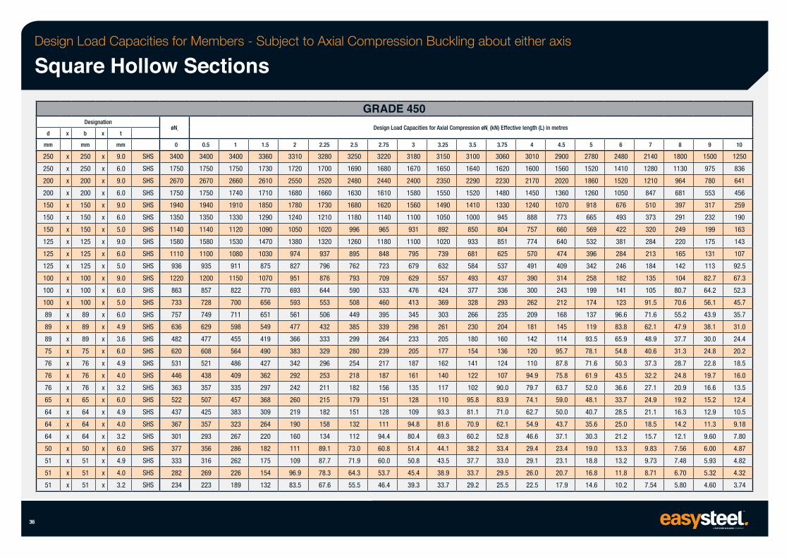
Design Load Capacities for Members - Subject to Axial Compression Buckling about either axis
Square Hollow Sections
36
d
mm
250
250
200
200
150
150
150
125
125
125
100
100
100
89
89
89
75
76
76
76
65
64
64
64
50
51
51
51
x
x
x
x
x
x
x
x
x
x
x
x
x
x
x
x
x
x
x
x
x
x
x
x
x
x
x
x
x
Designation
b
mm
250
250
200
200
150
150
150
125
125
125
100
100
100
89
89
89
75
76
76
76
65
64
64
64
50
51
51
51
x
x
x
x
x
x
x
x
x
x
x
x
x
x
x
x
x
x
x
x
x
x
x
x
x
x
x
x
x
t
mm
9.0
6.0
9.0
6.0
9.0
6.0
5.0
9.0
6.0
5.0
9.0
6.0
5.0
6.0
4.9
3.6
6.0
4.9
4.0
3.2
6.0
4.9
4.0
3.2
6.0
4.9
4.0
3.2
SHS
SHS
SHS
SHS
SHS
SHS
SHS
SHS
SHS
SHS
SHS
SHS
SHS
SHS
SHS
SHS
SHS
SHS
SHS
SHS
SHS
SHS
SHS
SHS
SHS
SHS
SHS
SHS
øNs
0
3400
1750
2670
1750
1940
1350
1140
1580
1110
936
1220
863
733
757
636
482
620
531
446
363
522
437
367
301
377
333
282
234
0.5
3400
1750
2670
1750
1940
1350
1140
1580
1100
935
1200
857
728
749
629
477
608
521
438
357
507
425
357
293
356
316
269
223
1
3400
1750
2660
1740
1910
1330
1120
1530
1080
911
1150
822
700
711
598
455
564
486
409
335
457
383
323
267
286
262
226
189
1.5
3360
1730
2610
1710
1850
1290
1090
1470
1030
875
1070
770
656
651
549
419
490
427
362
297
368
309
264
220
182
175
154
132
2
3310
1720
2550
1680
1780
1240
1050
1380
974
827
951
693
593
561
477
366
383
342
292
242
260
219
190
160
111
109
96.9
83.5
2.25
3280
1700
2520
1660
1730
1210
1020
1320
937
796
876
644
553
506
432
333
329
296
253
211
215
182
158
134
89.1
87.7
78.3
67.6
GRADE 450
2.5
3250
1690
2480
1630
1680
1180
996
1260
895
762
793
590
508
449
385
299
280
254
218
182
179
151
132
112
73.0
71.9
64.3
55.5
Design Load Capacities for Axial Compression øNc (kN) Effective length (L) in metres
2.75
3220
1680
2440
1610
1620
1140
965
1180
848
723
709
533
460
395
339
264
239
217
187
156
151
128
111
94.4
60.8
60.0
53.7
46.4
3
3180
1670
2400
1580
1560
1100
931
1100
795
679
629
476
413
345
298
233
205
187
161
135
128
109
94.8
80.4
51.4
50.8
45.4
39.3
3.25
3150
1650
2350
1550
1490
1050
892
1020
739
632
557
424
369
303
261
205
177
162
140
117
110
93.3
81.6
69.3
44.1
43.5
38.9
33.7
3.5
3100
1640
2290
1520
1410
1000
850
933
681
584
493
377
328
266
230
180
154
141
122
102
95.8
81.1
70.9
60.2
38.2
37.7
33.7
29.2
3.75
3060
1620
2230
1480
1330
945
804
851
625
537
437
336
293
235
204
160
136
124
107
90.0
83.9
71.0
62.1
52.8
33.4
33.0
29.5
25.5
4
3010
1600
2170
1450
1240
888
757
774
570
491
390
300
262
209
181
142
120
110
94.9
79.7
74.1
62.7
54.9
46.6
29.4
29.1
26.0
22.5
4.5
2900
1560
2020
1360
1070
773
660
640
474
409
314
243
212
168
145
114
95.7
87.8
75.8
63.7
59.0
50.0
43.7
37.1
23.4
23.1
20.7
17.9
5
2780
1520
1860
1260
918
665
569
532
396
342
258
199
174
137
119
93.5
78.1
71.6
61.9
52.0
48.1
40.7
35.6
30.3
19.0
18.8
16.8
14.6
6
2480
1410
1520
1050
676
493
422
381
284
246
182
141
123
96.6
83.8
65.9
54.8
50.3
43.5
36.6
33.7
28.5
25.0
21.2
13.3
13.2
11.8
10.2
7
2140
1280
1210
847
510
373
320
284
213
184
135
105
91.5
71.6
62.1
48.9
40.6
37.3
32.2
27.1
24.9
21.1
18.5
15.7
9.83
9.73
8.71
7.54
8
1800
1130
964
681
397
291
249
220
165
142
104
80.7
70.6
55.2
47.9
37.7
31.3
28.7
24.8
20.9
19.2
16.3
14.2
12.1
7.56
7.48
6.70
5.80
9
1500
975
780
553
317
232
199
175
131
113
82.7
64.2
56.1
43.9
38.1
30.0
24.8
22.8
19.7
16.6
15.2
12.9
11.3
9.60
6.00
5.93
5.32
4.60
10
1250
836
641
456
259
190
163
143
107
92.5
67.3
52.3
45.7
35.7
31.0
24.4
20.2
18.5
16.0
13.5
12.4
10.5
9.18
7.80
4.87
4.82
4.32
3.74
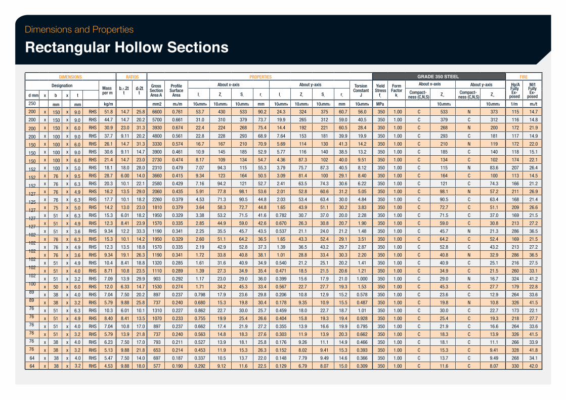
Dimensions and Properties
Rectangular Hollow Sections
d mm
250
200
200
200
200
150
150
150
152
152
152
127
125
127
127
127
102
102
102
102
102
102
100
89
89
76
76
76
76
76
76
64
64
x
x
x
x
x
x
x
x
x
x
x
x
x
x
x
x
x
x
x
x
x
x
x
x
x
x
x
x
x
x
x
x
x
x
DIMENSIONS
Designation
b
mm
150
150
150
100
100
100
100
100
76
76
76
76
75
51
51
51
76
76
76
51
51
51
50
38
38
51
51
51
51
38
38
38
38
x
x
x
x
x
x
x
x
x
x
x
x
x
x
x
x
x
x
x
x
x
x
x
x
x
x
x
x
x
x
x
x
x
x
t
mm
9.0
9.0
6.0
9.0
6.0
9.0
6.0
5.0
9.5
6.3
4.9
6.3
5.0
6.3
4.9
3.6
6.3
4.9
3.6
4.9
4.0
3.2
6.0
4.0
3.2
6.3
4.9
4.0
3.2
4.0
3.2
RHS
RHS
RHS
RHS
RHS
RHS
RHS
RHS
RHS
RHS
RHS
RHS
RHS
RHS
RHS
RHS
RHS
RHS
RHS
RHS
RHS
RHS
RHS
RHS
RHS
RHS
RHS
RHS
RHS
RHS
RHS
4.0
3.2
RHS
RHS
Mass per m
kg/m
51.8
44.7
30.9
37.7
26.1
30.6
21.4
18.1
28.7
20.3
16.2
17.7
14.2
15.3
12.3
9.34
15.3
12.3
9.34
10.4
8.71
7.09
12.0
7.04
5.79
10.3
8.40
7.04
5.79
6.23
5.13
5.47
4.53
RATIOS
b - 2t t
14.7
14.7
23.0
9.11
14.7
9.11
14.7
18.0
6.00
10.1
13.5
10.1
13.0
6.01
8.41
12.2
10.1
13.5
19.1
8.41
10.8
13.9
6.33
7.50
9.88
6.01
8.41
10.8
13.9
7.50
9.88
7.50
9.88
d-2t t
25.8
20.2
31.3
20.2
31.3
14.7
23.0
28.0
14.0
22.1
29.0
18.2
23.0
18.2
23.9
33.3
14.2
18.8
26.3
18.8
23.5
29.9
14.7
20.2
25.8
10.1
13.5
17.0
21.8
17.0
21.8
14.0
18.0
Section Gross
Area A
mm2
6600
5700
3930
4800
3330
3900
2730
2310
3660
2580
2060
2260
1810
1950
1570
1190
1950
1570
1190
1320
1110
903
1530
897
737
1310
1070
897
737
793
653
697
577
Surface Profile
Area
m2/m
0.761
0.661
0.674
0.561
0.574
0.461
0.474
0.479
0.415
0.429
0.435
0.379
0.379
0.329
0.335
0.341
0.329
0.335
0.341
0.285
0.289
0.292
0.274
0.237
0.240
0.227
0.233
0.237
0.240
0.211
0.214
0.187
0.190
Ix
106mm4
53.7
31.0
22.4
22.8
16.7
10.9
8.17
7.07
9.34
7.16
5.91
4.53
3.64
3.38
2.85
2.25
2.60
2.19
1.72
1.61
1.39
1.17
1.71
0.798
0.680
0.862
0.755
0.662
0.563
0.527
0.453
0.337
0.292
About x-axis
Zx
103mm3
430
310
224
228
167
145
109
94.3
123
94.2
77.8
71.3
58.3
53.2
44.9
35.5
51.1
42.9
33.8
31.6
27.3
23.0
34.2
17.9
15.3
22.7
19.9
17.4
14.8
13.9
11.9
10.5
9.12
Sx
PROPERTIES
103mm3
533
379
268
293
210
185
134
115
164
121
98.1
90.5
72.7
71.5
59.0
45.7
64.2
52.8
40.8
40.9
34.9
29.0
45.3
23.6
19.8
30.0
25.4
21.9
18.3
18.1
15.3
13.7
11.6
rx
mm
90.2
73.7
75.4
68.9
70.9
52.9
54.7
55.3
50.5
52.7
53.6
44.8
44.8
41.6
42.6
43.5
36.5
37.3
38.1
34.9
35.4
36.0
33.4
29.8
30.4
25.7
26.6
27.2
27.6
25.8
26.3
22.0
22.5
Iy
106mm4
24.3
19.9
14.4
7.64
5.69
5.77
4.36
3.79
3.09
2.41
2.01
2.03
1.65
0.782
0.670
0.537
1.65
1.39
1.01
0.540
0.471
0.399
0.567
0.206
0.178
0.459
0.404
0.355
0.303
0.176
0.152
0.148
0.129
About y-axis
Zy
103mm3
324
265
192
153
114
116
87.3
75.7
81.4
63.5
52.8
53.4
43.9
30.7
26.3
21.1
43.3
36.5
28.8
21.2
18.5
15.6
22.7
10.8
9.35
18.0
15.8
13.9
11.9
9.26
8.02
7.79
6.79
Sy
103mm3
375
312
221
181
130
140
102
87.3
100
74.3
60.6
63.4
51.1
37.0
30.8
24.0
52.4
43.2
33.4
25.1
21.5
17.9
27.7
12.9
10.9
22.7
19.3
16.6
13.9
11.1
9.41
9.49
8.07
ry
mm
60.7
59.0
60.5
39.9
41.3
38.5
40.0
40.5
29.1
30.6
31.2
30.0
30.2
20.0
20.7
21.2
29.1
29.7
30.3
20.2
20.6
21.0
19.3
15.2
15.5
18.7
19.4
19.9
20.3
14.9
15.3
14.6
15.0
Constant Torsion
J
106mm4
56.0
40.5
28.4
19.9
14.2
13.2
9.51
8.12
8.40
6.22
5.05
4.84
3.83
2.28
1.90
1.48
3.51
2.87
2.20
1.41
1.21
1.000
1.53
0.578
0.487
1.01
0.928
0.795
0.662
0.466
0.393
0.366
0.309
Stress Yield
fy
MPa
350
350
350
350
350
350
350
350
350
350
350
350
350
350
350
350
350
350
350
350
350
350
350
350
350
350
350
350
350
350
350
350
350
Factor Form
kf
1.00
1.00
1.00
1.00
1.00
1.00
1.00
1.00
1.00
1.00
1.00
1.00
1.00
1.00
1.00
1.00
1.00
1.00
1.00
1.00
1.00
1.00
1.00
1.00
1.00
1.00
1.00
1.00
1.00
1.00
1.00
1.00
1.00
GRADE 350 STEEL About x-axis
Compact- ness (C,N,S)
C
C
C
C
C
C
C
C
C
C
C
C
C
C
C
C
C
C
C
C
C
C
C
C
C
C
C
C
C
C
C
C
C
Zex
103mm3
533
379
268
293
210
185
134
115
164
121
98.1
90.5
72.7
71.5
59.0
45.7
64.2
52.8
40.8
40.9
34.9
29.0
45.3
23.6
19.8
30.0
25.4
21.9
18.3
18.1
15.3
13.7
11.6
About y-axis
Compact- ness (C,N,S)
N
C
N
C
N
C
C
N
C
C
N
C
C
C
C
N
C
C
N
C
C
N
C
C
N
C
C
C
C
C
C
C
C
Zey
103mm3
373
312
200
181
119
140
102
83.6
100
74.3
57.2
63.4
51.1
37.0
30.8
21.3
52.4
43.2
32.9
25.1
21.5
16.7
27.7
12.9
10.8
22.7
19.3
16.6
13.9
11.1
9.41
9.49
8.07
Hp/A Fully
FIRE
posed Ex-
1/m
115
116
172
117
172
118
174
207
113
166
211
168
209
169
213
286
169
213
286
216
260
324
179
264
326
173
218
264
326
266
328
268
330
Fully M/t
posed Ex-
m2/t
14.7
14.8
21.9
14.9
22.0
15.1
22.1
26.4
14.5
21.2
26.9
21.4
26.6
21.5
27.2
36.5
21.5
27.2
36.5
27.5
33.1
41.2
22.8
33.6
41.5
22.1
27.7
33.6
41.5
33.9
41.8
34.1
42.0
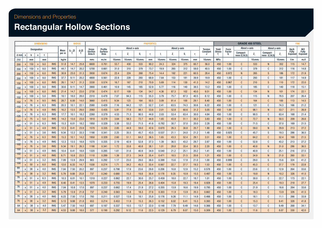
Dimensions and Properties
Rectangular Hollow Sections
d mm
250
200
200
200
200
150
150
150
152
152
152
127
125
127
127
127
102
102
102
102
102
102
100
89
89
76
76
76
76
76
76
x
x
x
x
x
x
x
x
x
x
x
x
64
64
x
x
x
x
x
x
x
x
x
x
x
x
x
x
x
x
x
x
x
x
x
x
DIMENSIONS
Designation
b
mm
150
150
150
100
100
100
100
100
76
76
76
76
75
51
51
51
76
76
76
51
51
51
50
38
38
51
51
51
51
38
38
38
38
x
x
x
x
x
x
x
x
x
x
x
x
x
x
x
x
x
x
x
x
x
x
x
x
x
x
x
x
x
x
x
x
x
x
t
mm
9.0
9.0
6.0
9.0
6.0
9.0
6.0
5.0
9.5
6.3
4.9
6.3
5.0
6.3
4.9
3.6
6.3
4.9
3.6
4.9
4.0
3.2
6.0
4.0
3.2
6.3
4.9
4.0
3.2
4.0
3.2
4.0
3.2
RHS
RHS
RHS
RHS
RHS
RHS
RHS
RHS
RHS
RHS
RHS
RHS
RHS
RHS
RHS
RHS
RHS
RHS
RHS
RHS
RHS
RHS
RHS
RHS
RHS
RHS
RHS
RHS
RHS
RHS
RHS
RHS
RHS
Mass per m
kg/m
51.8
44.7
30.9
37.7
26.1
30.6
21.4
18.1
28.7
20.3
16.2
17.7
14.2
15.3
12.3
9.34
15.3
12.3
9.34
10.4
8.71
7.09
12.0
7.04
5.79
10.3
8.40
7.04
5.79
6.23
5.13
5.47
4.53
RATIOS
b - 2t t
14.7
14.7
23.0
9.11
14.7
9.11
14.7
18.0
6.00
10.1
13.5
10.1
13.0
6.01
8.41
12.2
10.1
13.5
19.1
8.41
10.8
13.9
6.33
7.50
9.88
6.01
8.41
10.8
13.9
7.50
9.88
7.50
9.88
d-2t t
25.8
20.2
31.3
20.2
31.3
14.7
23.0
28.0
14.0
22.1
29.0
18.2
23.0
18.2
23.9
33.3
14.2
18.8
26.3
18.8
23.5
29.9
14.7
20.2
25.8
10.1
13.5
17.0
21.8
17.0
21.8
14.0
18.0
Section Gross
Area A
mm2
6600
5700
3930
4800
3330
3900
2730
2310
3660
2580
2060
2260
1810
1950
1570
1190
1950
1570
1190
1320
1110
903
1530
897
737
1310
1070
897
737
793
653
697
577
Surface Profile
Area
m2/m
0.761
0.661
0.674
0.561
0.574
0.461
0.474
0.479
0.415
0.429
0.435
0.379
0.379
0.329
0.335
0.341
0.329
0.335
0.341
0.285
0.289
0.292
0.274
0.237
0.240
0.227
0.233
0.237
0.240
0.211
0.214
0.187
0.190
Ix
106mm4
53.7
31.0
22.4
22.8
16.7
10.9
8.17
7.07
9.34
7.16
5.91
4.53
3.64
3.38
2.85
2.25
2.60
2.19
1.72
1.61
1.39
1.17
1.71
0.798
0.680
0.862
0.755
0.662
0.563
0.527
0.453
0.337
0.292
About x-axis
Zx
103mm3
430
310
224
228
167
145
109
94.3
123
94.2
77.8
71.3
58.3
53.2
44.9
35.5
51.1
42.9
33.8
31.6
27.3
23.0
34.2
17.9
15.3
22.7
19.9
17.4
14.8
13.9
11.9
10.5
9.12
PROPERTIES
Sx
103mm3
533
379
268
293
210
185
134
115
164
121
98.1
90.5
72.7
71.5
59.0
45.7
64.2
52.8
40.8
40.9
34.9
29.0
45.3
23.6
19.8
30.0
25.4
21.9
18.3
18.1
15.3
13.7
11.6
rx
mm
90.2
73.7
75.4
68.9
70.9
52.9
54.7
55.3
50.5
52.7
53.6
44.8
44.8
41.6
42.6
43.5
36.5
37.3
38.1
34.9
35.4
36.0
33.4
29.8
30.4
25.7
26.6
27.2
27.6
25.8
26.3
22.0
22.5
Iy
106mm4
24.3
19.9
14.4
7.64
5.69
5.77
4.36
3.79
3.09
2.41
2.01
2.03
1.65
0.782
0.670
0.537
1.65
1.39
1.01
0.540
0.471
0.399
0.567
0.206
0.178
0.459
0.404
0.355
0.303
0.176
0.152
0.148
0.129
About y-axis
Zy
103mm3
324
265
192
153
114
116
87.3
75.7
81.4
63.5
52.8
53.4
43.9
30.7
26.3
21.1
43.3
36.5
28.8
21.2
18.5
15.6
22.7
10.8
9.35
18.0
15.8
13.9
11.9
9.26
8.02
7.79
6.79
Sy
103mm3
375
312
221
181
130
140
102
87.3
100
74.3
60.6
63.4
51.1
37.0
30.8
24.0
52.4
43.2
33.4
25.1
21.5
17.9
27.7
12.9
10.9
22.7
19.3
16.6
13.9
11.1
9.41
9.49
8.07
ry
mm
60.7
59.0
60.5
39.9
41.3
38.5
40.0
40.5
29.1
30.6
31.2
30.0
30.2
20.0
20.7
21.2
29.1
29.7
30.3
20.2
20.6
21.0
19.3
15.2
15.5
18.7
19.4
19.9
20.3
14.9
15.3
14.6
15.0
Constant Torsion
J
106mm4
56.0
40.5
28.4
19.9
14.2
13.2
9.51
8.12
8.40
6.22
5.05
4.84
3.83
2.28
1.90
1.48
3.51
2.87
2.20
1.41
1.21
1.00
1.53
0.578
0.487
1.01
0.928
0.795
0.662
0.466
0.393
0.366
0.309
Stress Yield
fy
MPa
450
450
450
450
450
450
450
450
450
450
450
450
450
450
450
450
450
450
450
450
450
450
450
450
450
450
450
450
450
450
450
450
450
Factor Form
kf
1.00
1.00
0.972
1.00
0.967
1.00
1.00
1.00
1.00
1.00
1.00
1.00
1.00
1.00
1.00
0.925
1.00
1.00
1.00
1.00
1.00
0.999
1.00
1.00
1.00
1.00
1.00
1.00
1.00
1.00
1.00
1.00
1.00
GRADE 450 STEEL About x-axis
Compact- ness (C,N,S)
C
C
N
C
C
C
C
C
C
C
C
C
C
C
C
C
C
C
C
C
C
C
C
C
C
C
C
C
C
C
C
C
C
Zex
103mm3
533
379
265
293
210
185
134
115
164
121
98.1
90.5
72.7
71.5
59.0
45.7
64.2
52.8
40.8
40.9
34.9
29.0
45.3
23.6
19.8
30.0
25.4
21.9
18.3
18.1
15.3
13.7
11.6
About y-axis
Compact- ness (C,N,S)
N
C
S
C
S
C
N
N
C
C
N
C
N
C
N
S
C
C
N
C
N
S
C
C
N
C
C
C
C
C
C
C
C
Zey
103mm3
352
312
186
181
110
140
101
78.5
100
74.3
53.7
63.4
50.5
37.0
29.9
19.3
52.4
43.2
31.0
25.1
21.0
15.6
27.7
12.9
10.2
22.7
19.3
16.6
13.9
11.1
9.41
9.49
8.07
Hp/A
FIRE
Exposed Fully
1/m
115
116
172
117
172
118
174
207
113
166
211
168
209
169
213
286
169
213
286
216
260
324
179
264
326
173
218
264
326
266
328
268
330
Exposed Fully M/t
m2/t
14.7
14.8
21.9
14.9
22.0
15.1
22.1
26.4
14.5
21.2
26.9
21.4
26.6
21.5
27.2
36.5
21.5
27.2
36.5
27.5
33.1
41.2
22.8
33.6
41.5
22.1
27.7
33.6
41.5
33.9
41.8
34.1
42.0
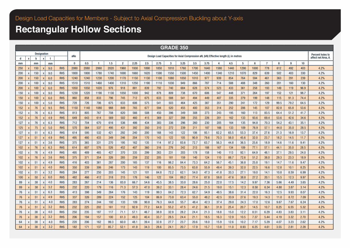
Design Load Capacities for Members - Subject to Axial Compression Buckling about Y-axis
Rectangular Hollow Sections
d
mm
250
200
200
200
200
150
150
150
152
152
152
127
125
127
127
127
102
102
102
102
102
102
100
89
89
76
76
76
76
76
76
64
64
x
x
x
x
x
x
x
x
x
x
x
x
x
x
x
x
x
x
x
x
x
x
x
x
x
x
x
x
x
x
x
x
x
x
Designation
b
mm
150
150
150
100
100
100
100
100
76
76
76
76
75
51
51
51
76
76
76
51
51
51
50
38
38
51
51
51
51
38
38
38
38
x
x
x
x
x
x
x
x
x
x
x
x
x
x
x
x
x
x
x
x
x
x
x
x
x
x
x
x
x
x
x
x
x
x
t
mm
9.0
9.0
6.0
9.0
6.0
9.0
6.0
5.0
9.5
6.3
4.9
6.3
5.0
6.3
4.9
3.6
6.3
4.9
3.6
4.9
4.0
3.2
6.0
4.0
3.2
6.3
4.9
4.0
3.2
4.0
3.2
4.0
3.2
RHS
RHS
RHS
RHS
RHS
RHS
RHS
RHS
RHS
RHS
RHS
RHS
RHS
RHS
RHS
RHS
RHS
RHS
RHS
RHS
RHS
RHS
RHS
RHS
RHS
RHS
RHS
RHS
RHS
RHS
RHS
RHS
RHS
øNs
0
2080
1800
1240
1510
1050
1230
860
728
1150
813
649
712
570
614
495
375
614
495
375
416
350
284
482
283
232
413
337
283
232
250
206
220
182
0.5
2080
1800
1240
1510
1050
1220
858
726
1140
805
643
704
564
595
480
365
607
489
371
403
339
277
466
267
220
398
326
274
225
235
194
206
171
1
2060
1780
1230
1460
1020
1190
833
706
1080
767
614
670
537
532
433
331
576
465
354
361
306
250
412
214
179
349
289
244
202
187
157
162
137
1.5
2020
1740
1200
1400
976
1130
796
675
988
708
569
616
495
421
349
270
526
427
326
287
246
203
318
136
116
264
224
192
161
117
100
99.3
85.7
2
1960
1690
1170
1310
918
1050
745
633
849
620
502
536
431
292
246
195
452
370
285
200
173
145
215
83.0
71.3
176
152
133
112
71.1
61.3
60.0
52.1
2.25
1930
1660
1150
1250
881
1000
712
606
765
566
460
486
392
240
204
162
407
335
259
165
143
121
176
66.7
57.3
143
125
109
92.9
57.1
49.3
48.1
41.9
GRADE 350 Design Load Capacities for Axial Compression øNc (kN) Effective length (L) in metres
2.5
1890
1620
1130
1190
839
942
675
575
677
508
415
434
350
200
170
135
360
299
232
137
119
101
146
54.6
47.0
119
104
90.8
77.2
46.7
40.4
39.4
34.3
2.75
1850
1590
1100
1110
792
878
633
541
594
450
369
383
310
168
143
114
316
263
205
116
100
84.8
122
45.5
39.2
99.3
86.9
76.3
64.9
38.9
33.7
32.8
28.6
3
1810
1550
1080
1030
740
809
588
503
520
396
327
336
272
143
122
97.2
276
231
181
98.2
85.5
72.2
104
38.5
33.1
84.2
73.8
64.8
55.2
32.9
28.5
27.7
24.1
3.25
1760
1500
1050
949
684
738
541
464
455
349
288
296
239
122
105
83.6
242
203
159
84.4
73.5
62.1
89.2
33.0
28.4
72.3
63.4
55.7
47.5
28.2
24.4
23.7
20.7
3.5
1700
1450
1010
866
628
670
494
425
400
308
255
260
211
106
90.9
72.7
213
178
140
73.3
63.8
54.0
77.4
28.6
24.6
62.7
55.0
48.4
41.2
24.4
21.1
20.6
17.9
3.75
1640
1400
977
787
574
606
449
387
353
273
226
230
187
93.1
79.6
63.7
188
158
124
64.2
55.9
47.3
67.8
25.0
21.5
54.9
48.2
42.3
36.1
21.3
18.5
18.0
15.7
4
1580
1340
939
714
523
547
407
351
314
243
201
205
166
82.2
70.3
56.3
167
140
110
56.7
49.4
41.8
59.8
22.0
19.0
48.5
42.5
37.4
31.9
18.8
16.3
15.9
13.8
4.5
1440
1210
854
588
433
448
335
290
252
195
162
164
133
65.5
56.0
44.8
134
113
88.7
45.1
39.3
33.3
47.6
17.5
15.1
38.6
33.9
29.8
25.4
15.0
12.9
12.6
11.0
5
1290
1070
764
488
361
371
279
241
206
160
133
135
109
53.3
45.6
36.5
109
92.1
72.6
36.8
32.0
27.1
38.8
14.2
12.3
31.4
27.6
24.3
20.7
12.2
10.5
10.2
8.93
6
1000
829
594
348
258
264
199
172
145
113
93.6
94.8
76.9
37.4
32.0
25.6
77.1
64.9
51.2
25.8
22.5
19.0
27.2
9.97
8.58
22.0
19.3
17.0
14.5
8.51
7.37
7.17
6.25
7
778
639
461
260
193
197
148
129
107
83.5
69.4
70.3
57.1
27.6
23.7
18.9
57.1
48.1
38.0
19.1
16.6
14.1
20.1
7.36
6.34
16.3
14.3
12.6
10.7
6.29
5.44
5.29
4.61
8
612
502
363
201
149
152
115
99.5
82.8
64.4
53.6
54.2
44.0
21.3
18.2
14.6
44.1
37.1
29.3
14.7
12.8
10.8
15.5
5.66
4.88
12.5
11.0
9.67
8.25
4.83
4.19
4.07
3.55
9
492
403
291
160
119
121
91.3
79.2
65.8
51.2
42.6
43.1
35.0
16.9
14.5
11.6
35.0
29.5
23.3
11.6
10.1
8.59
12.3
4.49
3.87
9.93
8.72
7.67
6.55
3.83
3.32
3.23
2.81
10
403
330
239
130
96.9
98.7
74.4
64.5
53.6
41.7
34.6
35.1
28.5
13.7
11.7
9.41
28.5
24.0
18.9
9.47
8.25
6.99
9.97
3.65
3.14
8.07
7.09
6.24
5.32
3.11
2.70
2.62
2.28
Percent holes to affect net Area, An
4.2%
4.2%
4.2%
4.2%
4.2%
4.2%
4.2%
4.2%
4.2%
4.2%
4.2%
4.2%
4.2%
4.2%
4.2%
4.2%
4.2%
4.2%
4.2%
4.2%
4.2%
4.2%
4.2%
4.2%
4.2%
4.2%
4.2%
4.2%
4.2%
4.2%
4.2%
4.2%
4.2%
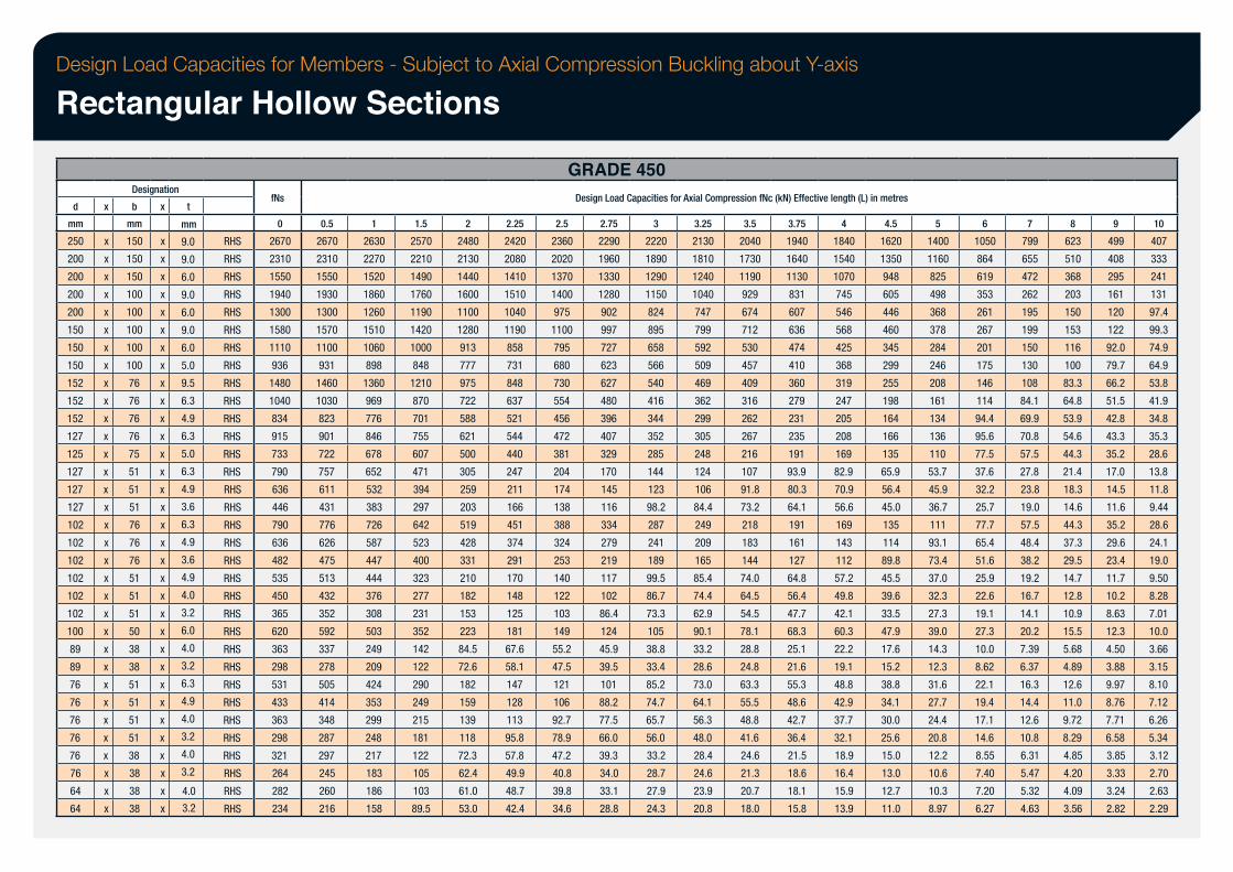
Design Load Capacities for Members - Subject to Axial Compression Buckling about Y-axis
Rectangular Hollow Sections
d
mm
250
200
200
200
200
150
150
150
152
152
152
127
125
127
127
127
102
102
102
102
102
102
100
89
89
76
76
76
76
76
76
64
64
x
x
x
x
x
x
x
x
x
x
x
x
x
x
x
x
x
x
x
x
x
x
x
x
x
x
x
x
x
x
x
x
x
x
Designation
b
mm
150
150
150
100
100
100
100
100
76
76
76
76
75
51
51
51
76
76
76
51
51
51
50
38
38
51
51
51
51
38
38
38
38
x
x
x
x
x
x
x
x
x
x
x
x
x
x
x
x
x
x
x
x
x
x
x
x
x
x
x
x
x
x
x
x
x
x
t
mm
9.0
9.0
6.0
9.0
6.0
9.0
6.0
5.0
9.5
6.3
4.9
6.3
5.0
6.3
4.9
3.6
6.3
4.9
3.6
4.9
4.0
3.2
6.0
4.0
3.2
6.3
4.9
4.0
3.2
4.0
3.2
4.0
3.2
RHS
RHS
RHS
RHS
RHS
RHS
RHS
RHS
RHS
RHS
RHS
RHS
RHS
RHS
RHS
RHS
RHS
RHS
RHS
RHS
RHS
RHS
RHS
RHS
RHS
RHS
RHS
RHS
RHS
RHS
RHS
RHS
RHS
fNs
0
2670
2310
1550
1940
1300
1580
1110
936
1480
1040
834
915
733
790
636
446
790
636
482
535
450
365
620
363
298
531
433
363
298
321
264
282
234
0.5
2670
2310
1550
1930
1300
1570
1100
931
1460
1030
823
901
722
757
611
431
776
626
475
513
432
352
592
337
278
505
414
348
287
297
245
260
216
1
2630
2270
1520
1860
1260
1510
1060
898
1360
969
776
846
678
652
532
383
726
587
447
444
376
308
503
249
209
424
353
299
248
217
183
186
158
1.5
2570
2210
1490
1760
1190
1420
1000
848
1210
870
701
755
607
471
394
297
642
523
400
323
277
231
352
142
122
290
249
215
181
122
105
103
89.5
2
2480
2130
1440
1600
1100
1280
913
777
975
722
588
621
500
305
259
203
519
428
331
210
182
153
223
84.5
72.6
182
159
139
118
72.3
62.4
61.0
53.0
2.25
2420
2080
1410
1510
1040
1190
858
731
848
637
521
544
440
247
211
166
451
374
291
170
148
125
181
67.6
58.1
147
128
113
95.8
57.8
49.9
48.7
42.4
GRADE 450 Design Load Capacities for Axial Compression fNc (kN) Effective length (L) in metres
2.5
2360
2020
1370
1400
975
1100
795
680
730
554
456
472
381
204
174
138
388
324
253
140
122
103
149
55.2
47.5
121
106
92.7
78.9
47.2
40.8
39.8
34.6
2.75
2290
1960
1330
1280
902
997
727
623
627
480
396
407
329
170
145
116
334
279
219
117
102
86.4
124
45.9
39.5
101
88.2
77.5
66.0
39.3
34.0
33.1
28.8
3
2220
1890
1290
1150
824
895
658
566
540
416
344
352
285
144
123
98.2
287
241
189
99.5
86.7
73.3
105
38.8
33.4
85.2
74.7
65.7
56.0
33.2
28.7
27.9
24.3
3.25
2130
1810
1240
1040
747
799
592
509
469
362
299
305
248
124
106
84.4
249
209
165
85.4
74.4
62.9
90.1
33.2
28.6
73.0
64.1
56.3
48.0
28.4
24.6
23.9
20.8
3.5
2040
1730
1190
929
674
712
530
457
409
316
262
267
216
107
91.8
73.2
218
183
144
74.0
64.5
54.5
78.1
28.8
24.8
63.3
55.5
48.8
41.6
24.6
21.3
20.7
18.0
3.75
1940
1640
1130
831
607
636
474
410
360
279
231
235
191
93.9
80.3
64.1
191
161
127
64.8
56.4
47.7
68.3
25.1
21.6
55.3
48.6
42.7
36.4
21.5
18.6
18.1
15.8
4
1840
1540
1070
745
546
568
425
368
319
247
205
208
169
82.9
70.9
56.6
169
143
112
57.2
49.8
42.1
60.3
22.2
19.1
48.8
42.9
37.7
32.1
18.9
16.4
15.9
13.9
4.5
1620
1350
948
605
446
460
345
299
255
198
164
166
135
65.9
56.4
45.0
135
114
89.8
45.5
39.6
33.5
47.9
17.6
15.2
38.8
34.1
30.0
25.6
15.0
13.0
12.7
11.0
5
1400
1160
825
498
368
378
284
246
208
161
134
136
110
53.7
45.9
36.7
111
93.1
73.4
37.0
32.3
27.3
39.0
14.3
12.3
31.6
27.7
24.4
20.8
12.2
10.6
10.3
8.97
6
1050
864
619
353
261
267
201
175
146
114
94.4
95.6
77.5
37.6
32.2
25.7
77.7
65.4
51.6
25.9
22.6
19.1
27.3
10.0
8.62
22.1
19.4
17.1
14.6
8.55
7.40
7.20
6.27
7
799
655
472
262
195
199
150
130
108
84.1
69.9
70.8
57.5
27.8
23.8
19.0
57.5
48.4
38.2
19.2
16.7
14.1
20.2
7.39
6.37
16.3
14.4
12.6
10.8
6.31
5.47
5.32
4.63
8
623
510
368
203
150
153
116
100
83.3
64.8
53.9
54.6
44.3
21.4
18.3
14.6
44.3
37.3
29.5
14.7
12.8
10.9
15.5
5.68
4.89
12.6
11.0
9.72
8.29
4.85
4.20
4.09
3.56
9
499
408
295
161
120
122
92.0
79.7
66.2
51.5
42.8
43.3
35.2
17.0
14.5
11.6
35.2
29.6
23.4
11.7
10.2
8.63
12.3
4.50
3.88
9.97
8.76
7.71
6.58
3.85
3.33
3.24
2.82
10
407
333
241
131
97.4
99.3
74.9
64.9
53.8
41.9
34.8
35.3
28.6
13.8
11.8
9.44
28.6
24.1
19.0
9.50
8.28
7.01
10.0
3.66
3.15
8.10
7.12
6.26
5.34
3.12
2.70
2.63
2.29
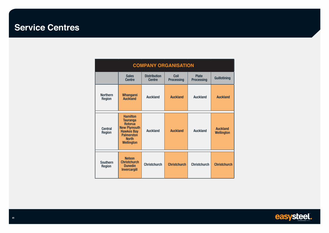
Service Centres
41
Northern Region
Central Region
Southern Region
Sales Centre
Whangarei Auckland
Hamilton Tauranga Rotorua
New Plymouth Hawkes Bay Palmerston
North Wellington
Nelson Christchurch
Dunedin Invercargill
Distribution Centre
Auckland
Auckland
Christchurch
Coil Processing
Auckland
Auckland
Christchurch
Plate Processing
Auckland
Auckland
Christchurch
Guillotining
Auckland
Auckland Wellington
Christchurch
COMPANY ORGANISATION
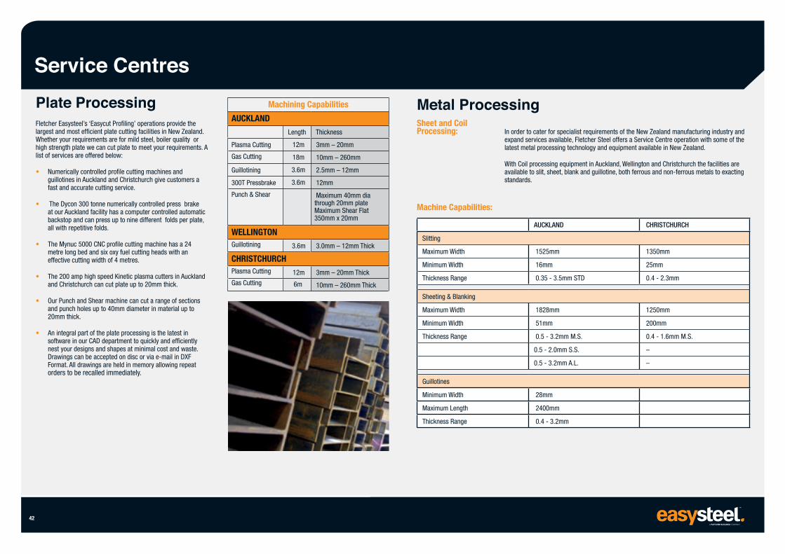
Service Centres Plate Processing Fletcher Easysteel’s ‘Easycut Profiling’ operations provide the largest and most efficient plate cutting facilities in New Zealand. Whether your requirements are for mild steel, boiler quality or high strength plate we can cut plate to meet your requirements. A list of services are offered below:
• Numerically controlled profile cutting machines and guillotines in Auckland and Christchurch give customers a fast and accurate cutting service.
• The Dycon 300 tonne numerically controlled press brake at our Auckland facility has a computer controlled automatic backstop and can press up to nine different folds per plate, all with repetitive folds.
• The Mynuc 5000 CNC profile cutting machine has a 24 metre long bed and six oxy fuel cutting heads with an effective cutting width of 4 metres.
• The 200 amp high speed Kinetic plasma cutters in Auckland and Christchurch can cut plate up to 20mm thick.
• Our Punch and Shear machine can cut a range of sections and punch holes up to 40mm diameter in material up to 20mm thick.
• An integral part of the plate processing is the latest in software in our CAD department to quickly and efficiently nest your designs and shapes at minimal cost and waste. Drawings can be accepted on disc or via e-mail in DXF Format. All drawings are held in memory allowing repeat orders to be recalled immediately.
42
Machining Capabilities
AUCKLAND
Plasma Cutting
Gas Cutting
Guillotining
300T Pressbrake
Punch & Shear
WELLINGTON Guillotining
Length
12m
18m
3.6m
3.6m
3.6m
CHRISTCHURCH Plasma Cutting
Gas Cutting
12m
6m
Thickness
3mm – 20mm
10mm – 260mm
2.5mm – 12mm
12mm
Maximum 40mm dia through 20mm plate Maximum Shear Flat 350mm x 20mm
3.0mm – 12mm Thick
3mm – 20mm Thick
10mm – 260mm Thick
Metal Processing Sheet and Coil Processing: In order to cater for specialist requirements of the New Zealand manufacturing industry and
expand services available, Fletcher Steel offers a Service Centre operation with some of the latest metal processing technology and equipment available in New Zealand.
With Coil processing equipment in Auckland, Wellington and Christchurch the facilities are available to slit, sheet, blank and guillotine, both ferrous and non-ferrous metals to exacting standards.
Machine Capabilities:
Slitting
Maximum Width
Minimum Width
Thickness Range
Sheeting & Blanking
Maximum Width
Minimum Width
Thickness Range
Guillotines
Minimum Width
Maximum Length
Thickness Range
AUCKLAND
1525mm
16mm
0.35 - 3.5mm STD
1828mm
51mm
0.5 - 3.2mm M.S.
0.5 - 2.0mm S.S.
0.5 - 3.2mm A.L.
28mm
2400mm
0.4 - 3.2mm
CHRISTCHURCH
1350mm
25mm
0.4 - 2.3mm
1250mm
200mm
0.4 - 1.6mm M.S.
–
–
Indent
Services
Indent Sourcing
For the products and quantities outside our stocking policy, Fletcher Easysteel has many years of experience in sourcing a comprehensive range of steel and related products for our customers for the products and quantities outside our stocked range. The resulting well established channels, relationships with suppliers, and collective purchasing leverage means Fletcher Easysteel is well positioned to cater for your indent requirements.
Further, our ability to co-ordinate indent orders in a centralised operation ensures excellent service at all times.
In addition to our normal ex-stock range which can also be sourced through indent, Fletcher Easysteel has indent channels for an extensive range of products which include the following:
Flat Rolled Steel Products:
• Tin Plate and Tin Free Steel
• Terne Sheet
• Electrical Steels
• Electrogalv Steel
• Hot Dip Galvanised Steel
• Galfan
• Zincalume
• Cold Rolled Sheet and Coil (all grades)
• Prepainted Sheet and Coil
• Enamelling Sheet and Coil
• Aluminised Sheet and Coil
• High Carbon Steel and Coil
• Steel Sheet Piling
• 7 Wire Strand and Wire
• Steel Rails
• Spring Steels
• Boiler Tubes
• Head Plates (Dished Ends)
• Tool Steels
• Forgings
• Titanium
• Hollow Bar
• Inconel - Nickel Alloys
• Elmedur - Copper Alloys
Please contact your local Easysteel Sales Centre with your enquiry.
43
WHANGAREI33 Rewarewa RoadPO Box 292, Whangarei 0140Ph: 09 470 2510 Fax: 09 438 4589
AUCKLAND575 Great South RoadPrivate Bag 92803Penrose, Auckland 1642Ph: 09 525 9400 Fax: 09 525 9401
HAMILTONEllis Street, FranktonPO Box 828, Hamilton 3240Ph: 07 846 2700 Fax: 07 846 2708
TAURANGA99 Aviation AvenueMt MaunganuiPO Box 450, Tauranga 3140Ph: 07 572 9700 Fax: 07 572 9707
ROTORUATallyho StreetPO Box 331, Rotorua 3040Ph: 07 348 3039 Fax: 07 347 7353
NEW PLYMOUTH50 Corbett RoadBell BlockNew Plymouth 4342Ph: 06 755 9039 Fax: 06 755 2099
HAWKES BAY1100 Omahu RoadRD 5, Hastings 4175Ph: 06 873 9036 Fax: 06 879 6880
PALMERSTON NORTH118-120 Kaimanawa StreetKelvin GrovePalmerston North 4414Ph: 06 354 2622 Fax: 06 354 2623
WELLINGTONBurnham StreetPO Box 33-254 Petone, Wellington 5046Ph: 04 570 8472 Fax: 04 570 8473
NORTH ISLAND
SOUTH ISLAND
easysteel.co.nz
NELSON40-42 Beach Road, Richmond, Nelson 7050Ph: 03 543 8215 Fax: 0800 432 793
CHRISTCHURCH5 Brydone RoadHornby South, Christchurch 8042Ph: 03 348 8479 Fax: 03 343 0320
DUNEDIN26 Orari StreetSouth Dunedin, Dunedin 9012Ph: 0800 327 978 Fax: 0800 432 793
INVERCARGILL54 Tweed Street PO Box 957, Invercargill 9840Ph: 03 211 0696 Fax: 03 218 2318
As part of Fletcher Easysteel’s policy of continued product improvement, the company reserves the right, at any time, at their discretion and without notice to discontinue or change the features, designs, materials, colours and other specifications of their product and to either permanently or temporarily withdraw any such products from the market without incurring any liability. This publication is issued as a general guide only and should not be treated as a substitute for detailed technical advice in relation to individual circumstances. Fletcher Easysteel disclaim any liability for loss or damage suffered from the use of such data. To the best of our knowledge, all information is correct at the time of printing. A division of Fletcher Building Ltd. Copyright 2016.