structural redesign two way slab / drop panels redesign.pdfstructural redesign two way slab / drop...
TRANSCRIPT
Structural Redesign
Two way slab / Drop panels
My redesign of Fordham Place will comprise of a 9” flat slab
with 5 ½” drop panels. Materials used for this redesign is
normal weight concrete with compressive strength of 4ksi and
steel rebar with a yield stress of 60 ksi. Floor slab thickness
was determined by ACI 318-02 table 9.5(c) using exterior
panels, without edge beams, but with drop panels to get
minimum floor slab thickness of ℓn/36. Where ℓn = 28’ – 2’ =
26’, and the value ℓn/36 = (26’ x 12”) / 36 = 8.67”. At first I
determined the drop projection of ¼ tslab from ACI 318-02
section 13.3.7.2. Where ¼ tslab = 9”/4 = 2.25”. In order to form
the drops with 2 x 4’s or 2 x 6’s, drop projection needs to be
either 3.5” or 5.5”. Therefore drop projections were 3.5”.
However, when analyzed in ADOSS, a 3.5” drop did not
provide sufficient shear capacity. I then changed the drop
projection to 5.5” and determined the slab had sufficient shear
capacity.
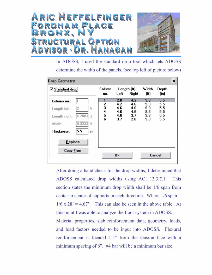
In ADOSS, I used the standard drop tool which lets ADOSS
determine the width of the panels. (see top left of picture below)
T
h
e
d
r
o
p
A
After doing a hand check for the drop widths, I determined that
ADOSS calculated drop widths using ACI 13.3.7.1. This
section states the minimum drop width shall be 1/6 span from
center to center of supports in each direction. Where 1/6 span =
1/6 x 28’ = 4.67’. This can also be seen in the above table. At
this point I was able to analyze the floor system in ADOSS.
Material properties, slab reinforcement data, geometry, loads,
and load factors needed to be input into ADOSS. Flexural
reinforcement is located 1.5” from the tension face with a
minimum spacing of 6”. #4 bar will be a minimum bar size.
Minimum reinforcement ratio is
(As)min = 0.0018 Ag ACI 7.12.2.1
= 0.0018 x 9” x 12”
= 0.19 in2/ft
Therefore the minimum flexural reinforcement will be
#4’s @ 12”.
In order to simplify the design of the slab and columns, there
was an assumption that shear walls would resist 100% of the
lateral load; leaving the slab and columns to resist only gravity
loads. Gravity loads that were considered were dead, live, roof
live, and snow. The following is a list of the loads that were
used in designing the concrete system.
Superimposed Dead = 30psf
Live = 80psf
Roof live / snow = 30psf
Live loads were reduced to lesser values based on ASCE 7-02.
(See Appendix for complete calculations)
After inputting this information into ADOSS, I was then able to
design the system. The following is part of an ADOSS output
file showing positive and negative reinforcement. Although
ADOSS does design the number and spacing of bars, it was not
very uniform throughout the different spans of the slab even
though the total amount of steel required was similar.
Therefore from the output file, I determined the amount of steel
per foot width and selected bar size and spacing. This was done
for both column and middle strips. Having a more uniform
steel layout throughout the building reduces the chance of a
mistake in the field where a contractor may place the rebar
incorrectly.
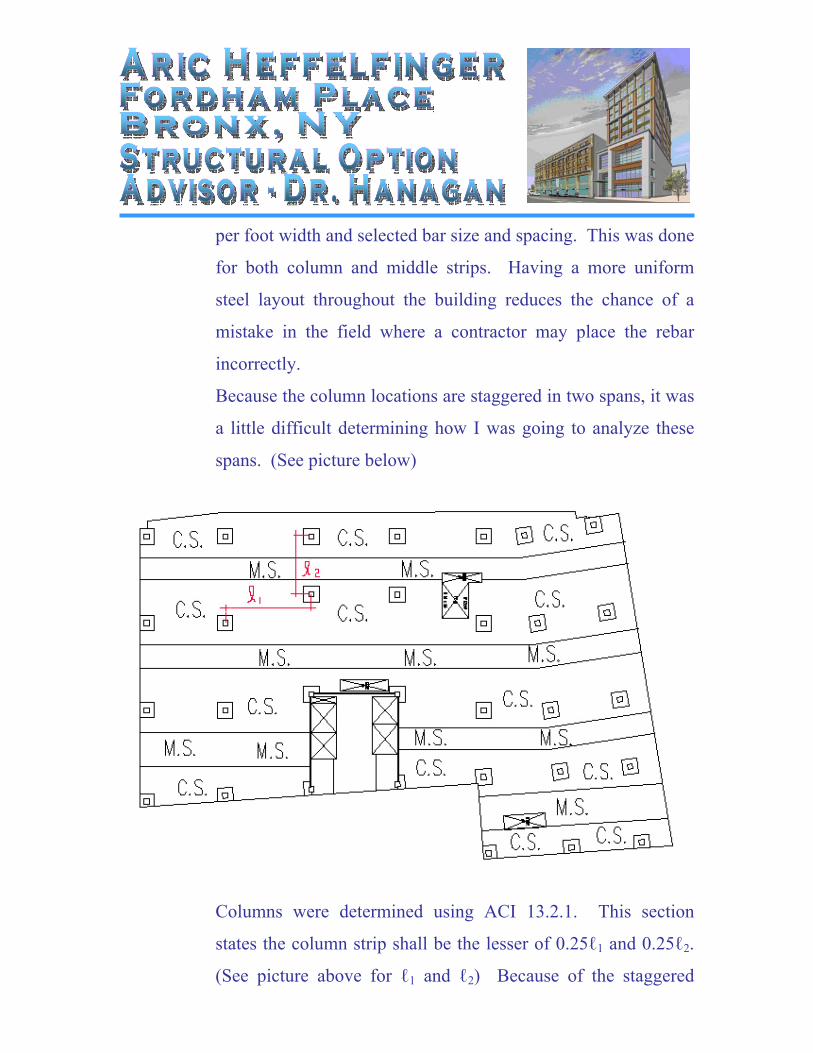
Because the column locations are staggered in two spans, it was
a little difficult determining how I was going to analyze these
spans. (See picture below)
Columns were determined using ACI 13.2.1. This section
states the column strip shall be the lesser of 0.25ℓ1 and 0.25ℓ2.
(See picture above for ℓ1 and ℓ2) Because of the staggered
columns, I decided to just make the area between those columns
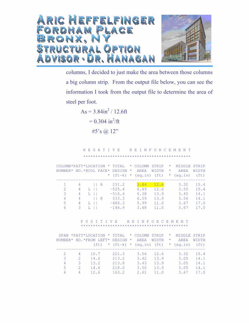
a big column strip. From the output file below, you can see the
information I took from the output file to determine the area of
steel per foot.
As = 3.84in2 / 12.6ft
= 0.304 in2/ft
#5’s @ 12”
N E G A T I V E R E I N F O R C E M E N T
******************************************** COLUMN*PATT*LOCATION * TOTAL * COLUMN STRIP * MIDDLE STRIP NUMBER* NO.*@COL FACE* DESIGN * AREA WIDTH * AREA WIDTH * (ft-k) * (sq.in) (ft) * (sq.in) (ft) ------------------------------------------------------------- 1 4 || R 231.2 3.84 12.6 3.32 15.4 2 4 L || -525.4 6.49 12.6 3.50 15.4 3 4 L || -516.4 6.38 13.9 3.45 14.1 4 4 || R 533.3 6.59 13.9 3.56 14.1 5 4 L || -486.3 5.99 11.0 3.67 17.0 6 3 L || -146.9 3.48 11.0 3.67 17.0 P O S I T I V E R E I N F O R C E M E N T ******************************************** SPAN *PATT*LOCATION * TOTAL * COLUMN STRIP * MIDDLE STRIP NUMBER* NO.*FROM LEFT* DESIGN * AREA WIDTH * AREA WIDTH (ft) * (ft-k) * (sq.in) (ft) * (sq.in) (ft) ------------------------------------------------------------- 2 4 10.7 221.3 3.56 12.6 3.32 15.4 3 2 14.6 213.2 3.42 13.9 3.05 14.1 4 3 13.2 213.8 3.43 13.9 3.05 14.1 5 2 14.6 218.0 3.50 13.9 3.05 14.1 6 4 12.6 163.2 2.61 11.0 3.67 17.0
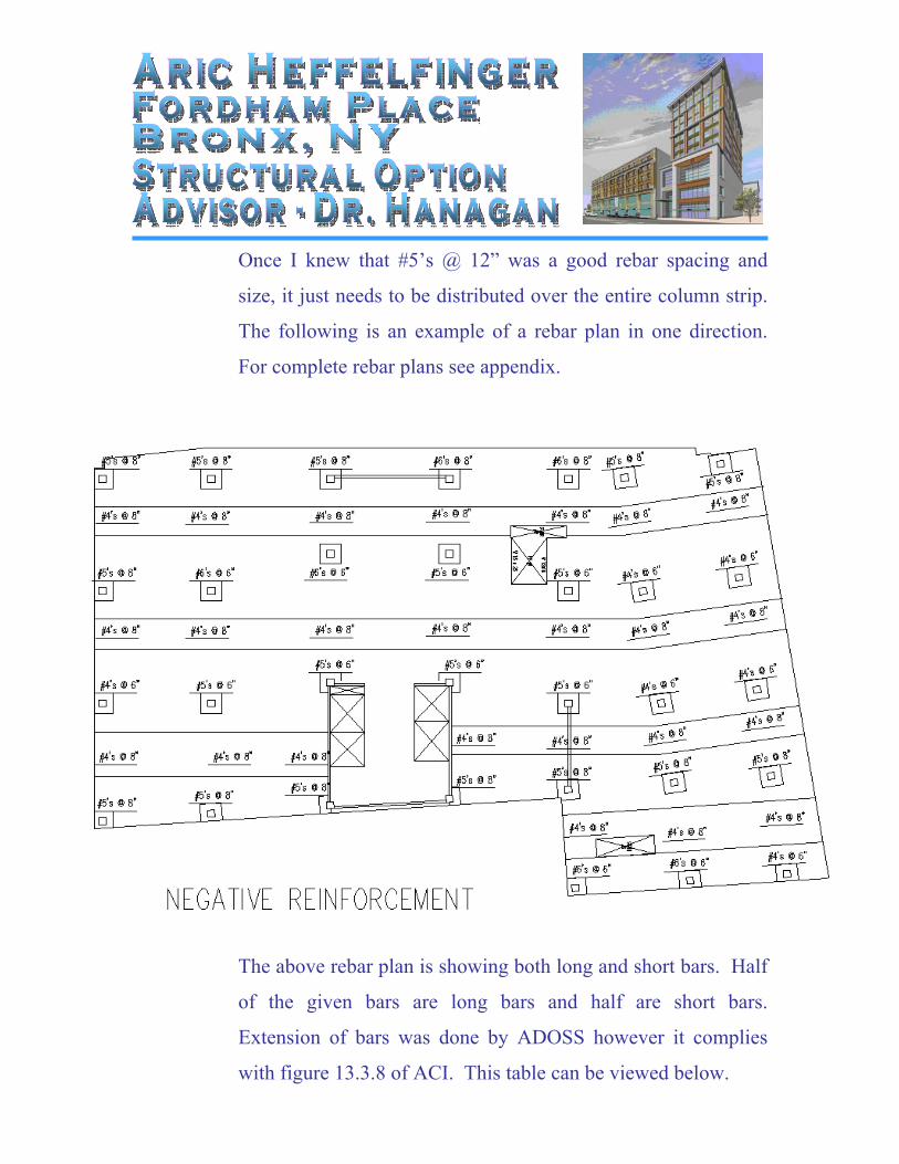
Once I knew that #5’s @ 12” was a good rebar spacing and
size, it just needs to be distributed over the entire column strip.
The following is an example of a rebar plan in one direction.
For complete rebar plans see appendix.
The above rebar plan is showing both long and short bars. Half
of the given bars are long bars and half are short bars.
Extension of bars was done by ADOSS however it complies
with figure 13.3.8 of ACI. This table can be viewed below.
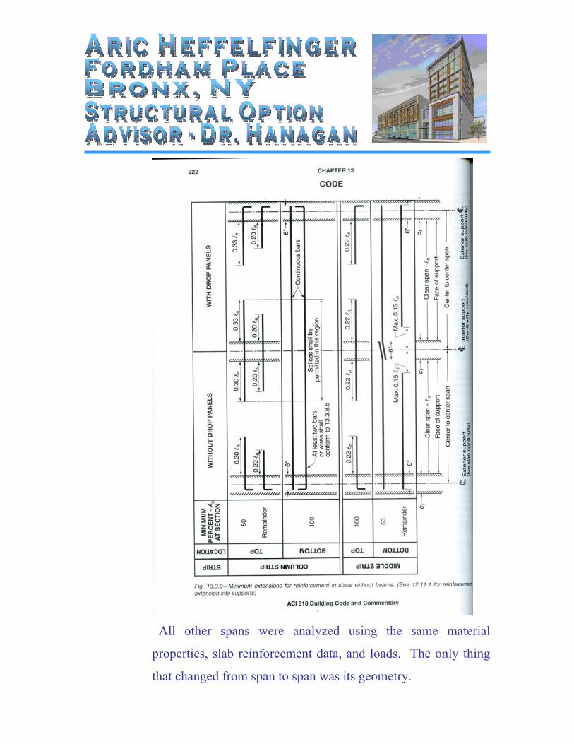
All other spans were analyzed using the same material
properties, slab reinforcement data, and loads. The only thing
that changed from span to span was its geometry.
Columns
The columns at Fordham Place are 26” x 26” normal weight
concrete throughout the entire building. The concrete
compressive strength is primarily 4ksi, however there are some
8ksi columns on the bottom 5 floors which support large
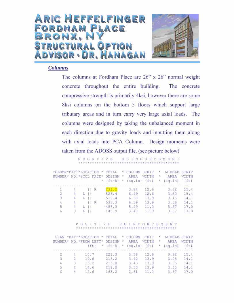
tributary areas and in turn carry very large axial loads. The
columns were designed by taking the unbalanced moment in
each direction due to gravity loads and inputting them along
with axial loads into PCA Column. Design moments were
taken from the ADOSS output file. (see picture below) N E G A T I V E R E I N F O R C E M E N T ******************************************** COLUMN*PATT*LOCATION * TOTAL * COLUMN STRIP * MIDDLE STRIP NUMBER* NO.*@COL FACE* DESIGN * AREA WIDTH * AREA WIDTH * (ft-k) * (sq.in) (ft) * (sq.in) (ft) ------------------------------------------------------------- 1 4 || R 231.2 3.84 12.6 3.32 15.4 2 4 L || -525.4 6.49 12.6 3.50 15.4 3 4 L || -516.4 6.38 13.9 3.45 14.1 4 4 || R 533.3 6.59 13.9 3.56 14.1 5 4 L || -486.3 5.99 11.0 3.67 17.0 6 3 L || -146.9 3.48 11.0 3.67 17.0 P O S I T I V E R E I N F O R C E M E N T ******************************************** SPAN *PATT*LOCATION * TOTAL * COLUMN STRIP * MIDDLE STRIP NUMBER* NO.*FROM LEFT* DESIGN * AREA WIDTH * AREA WIDTH (ft) * (ft-k) * (sq.in) (ft) * (sq.in) (ft) ------------------------------------------------------------- 2 4 10.7 221.3 3.56 12.6 3.32 15.4 3 2 14.6 213.2 3.42 13.9 3.05 14.1 4 3 13.2 213.8 3.43 13.9 3.05 14.1 5 2 14.6 218.0 3.50 13.9 3.05 14.1 6 4 12.6 163.2 2.61 11.0 3.67 17.0
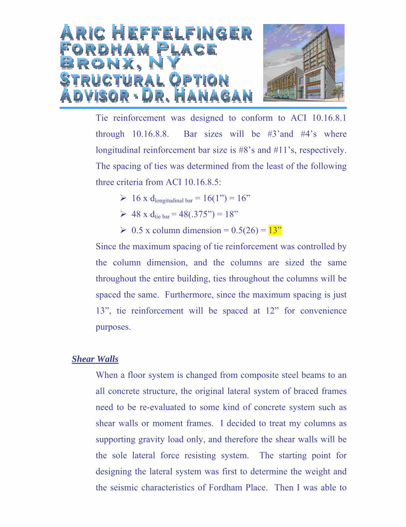
Also, design axial loads were determined using an excel
spreadsheet that multiplied tributary area by self weight,
superimposed dead load, reduced live load, and roof live load.
(See table below)
The following is a list of other design criteria that was used for
the concrete columns at Fordham Place:
Minimum Reinforcement Ratio = 0.01
Maximum Reinforcement Ration = 0.08
Minimum Clear spacing between bars = 1.5”
Minimum Clear cover = 0.75”
Minimum bar size = #8
Maximum Bar Size = #11
Longitudinal reinforcement in columns at a minimum is 12 - #11’s.
This is the next smallest reinforcement ratio = 0.014 > 0.01.
Tie reinforcement was designed to conform to ACI 10.16.8.1
through 10.16.8.8. Bar sizes will be #3’and #4’s where
longitudinal reinforcement bar size is #8’s and #11’s, respectively.
The spacing of ties was determined from the least of the following
three criteria from ACI 10.16.8.5:
16 x dlongitudinal bar = 16(1”) = 16”
48 x dtie bar = 48(.375”) = 18”
0.5 x column dimension = 0.5(26) = 13”
Since the maximum spacing of tie reinforcement was controlled by
the column dimension, and the columns are sized the same
throughout the entire building, ties throughout the columns will be
spaced the same. Furthermore, since the maximum spacing is just
13”, tie reinforcement will be spaced at 12” for convenience
purposes.
Shear Walls
When a floor system is changed from composite steel beams to an
all concrete structure, the original lateral system of braced frames
need to be re-evaluated to some kind of concrete system such as
shear walls or moment frames. I decided to treat my columns as
supporting gravity load only, and therefore the shear walls will be
the sole lateral force resisting system. The starting point for
designing the lateral system was first to determine the weight and
the seismic characteristics of Fordham Place. Then I was able to
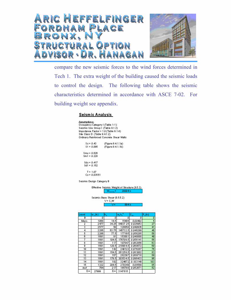
compare the new seismic forces to the wind forces determined in
Tech 1. The extra weight of the building caused the seismic loads
to control the design. The following table shows the seismic
characteristics determined in accordance with ASCE 7-02. For
building weight see appendix.
After determining the story forces located at each floor level,
lateral forces were distributed based on stiffness of each shear
wall. Since my shear walls are not at the face of the building, the
floor slab will have to axially transfer lateral loads on the building
to the shear walls. Once the lateral forces reach the shear walls,
they will act as point loads on the shear walls. To design the shear
walls, I treated the wall as a gigantic cantilever beam with
numerous point loads. The following is a diagram of the most
severely loaded shear wall showing lateral forces on the wall.
However, every shear wall will be designed the same for
simplification purposes.
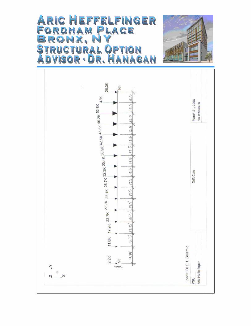
At this point I was able to determine shear and moment diagrams.
The max shear was determined to be 502k and was located at the
fixed based of the “cantilever beam”. The final design of shear
reinforcement in the wall was #5’s at 12” for the first 1/3 of the
building height. The second third will contain #5’s at 24”, while
the last third will not require shear reinforcement. When I move
on to designing the flexural reinforcement, I discovered I would
need a lot more steel than I had originally estimated. (As =
53.7in2) With using a 12” shear wall, it was merely impossible to
stuff this steel into the end of the wall with only 1ft width. From
here I decided to use a flanged shear wall. The flanged shear wall
consisted of the exact same design, but allowed me to fit all the
steel in a reasonable configuration. The dimensions of the flanged
section are 3ft flange width with a flange thickness of 1ft. There
will be 3 rows of 11 - #11’s within the flange while 1 row of 3 -
#11’s are just inside the web. See picture below
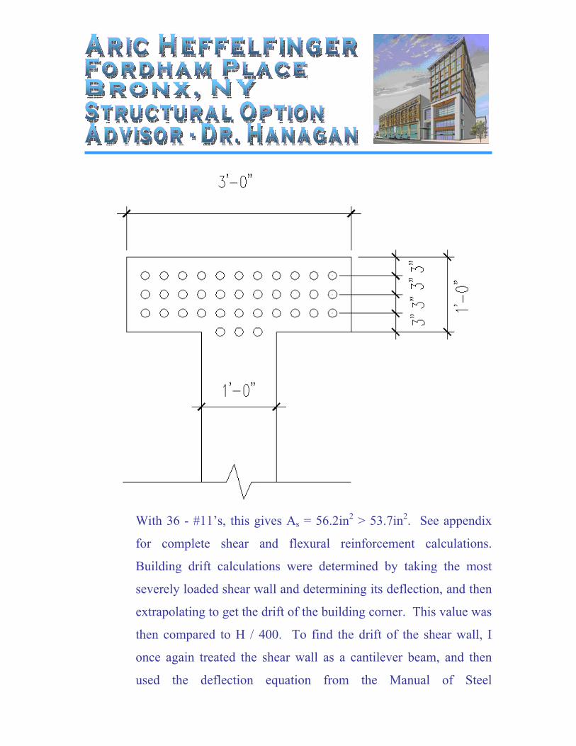
With 36 - #11’s, this gives As = 56.2in2 > 53.7in2. See appendix
for complete shear and flexural reinforcement calculations.
Building drift calculations were determined by taking the most
severely loaded shear wall and determining its deflection, and then
extrapolating to get the drift of the building corner. This value was
then compared to H / 400. To find the drift of the shear wall, I
once again treated the shear wall as a cantilever beam, and then
used the deflection equation from the Manual of Steel
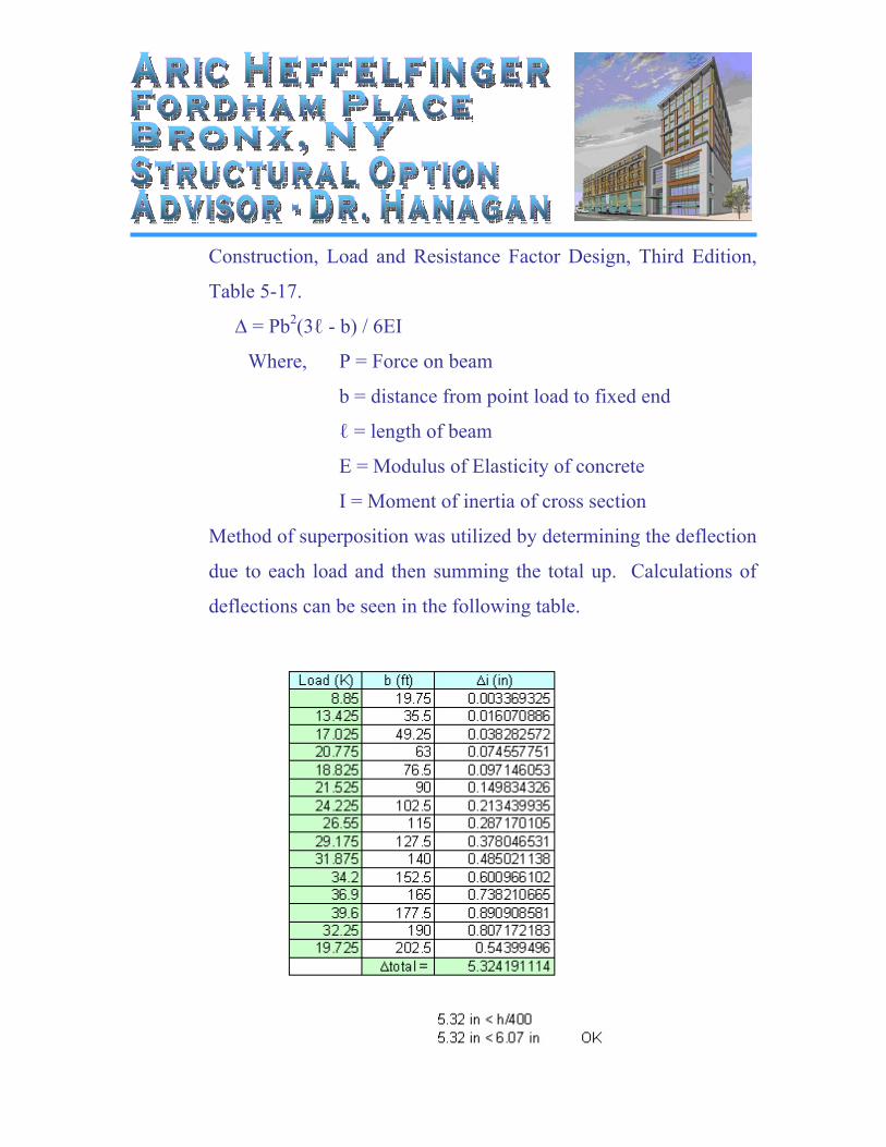
Construction, Load and Resistance Factor Design, Third Edition,
Table 5-17.
∆ = Pb2(3ℓ - b) / 6EI
Where, P = Force on beam
b = distance from point load to fixed end
ℓ = length of beam
E = Modulus of Elasticity of concrete
I = Moment of inertia of cross section
Method of superposition was utilized by determining the deflection
due to each load and then summing the total up. Calculations of
deflections can be seen in the following table.
Special Areas throughout Building
There are a couple different areas throughout the building that
required a little extra attention and also a modification to the
standard designs. These areas comprise of an atrium space on
second floor, a mezzanine floor that resulted in columns with large
unbraced lengths, and a large span in the floor slab.
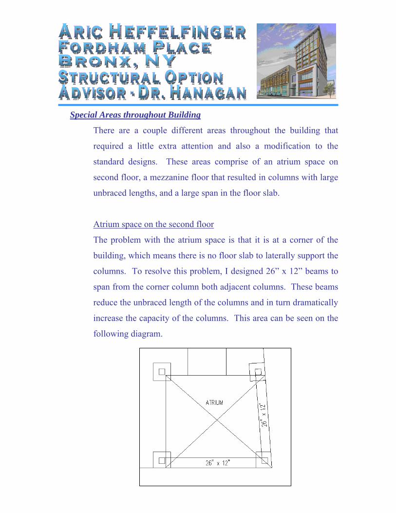
Atrium space on the second floor
The problem with the atrium space is that it is at a corner of the
building, which means there is no floor slab to laterally support the
columns. To resolve this problem, I designed 26” x 12” beams to
span from the corner column both adjacent columns. These beams
reduce the unbraced length of the columns and in turn dramatically
increase the capacity of the columns. This area can be seen on the
following diagram.
Mezzanine floor / columns with large unbraced lengths
There is a mezzanine floor between the ground and second floors
that covers only about ¼ of the building footprint. This makes
about ¾ of the columns be designed with a large unbraced length.
The typical 26” x 26” 4ksi column did not have the capacity to
carry required loads with this large unbraced length. However
since there were a few columns that carried extremely large axial
loads and required 8ksi concrete, this gave me another option to
look at. The question was then; would these columns have
sufficient capacity using 8 ksi concrete? After running a few of the
critical columns in PCA Column with 8ksi concrete, I was able to
determine that yes, the 8ksi concrete did provide enough capacity
for the given unbraced length.
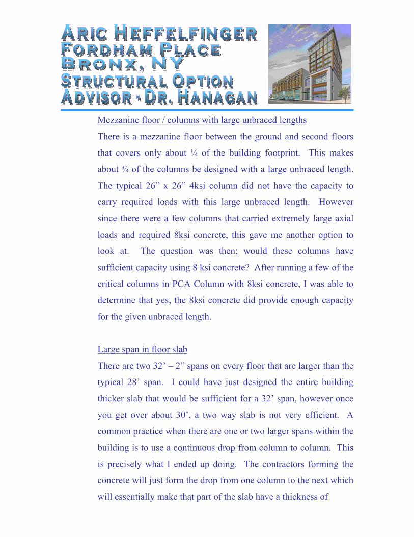
Large span in floor slab
There are two 32’ – 2” spans on every floor that are larger than the
typical 28’ span. I could have just designed the entire building
thicker slab that would be sufficient for a 32’ span, however once
you get over about 30’, a two way slab is not very efficient. A
common practice when there are one or two larger spans within the
building is to use a continuous drop from column to column. This
is precisely what I ended up doing. The contractors forming the
concrete will just form the drop from one column to the next which
will essentially make that part of the slab have a thickness of
t = 9” + 5.5”
= 14.5”
Reinforcement will be placed at 0.75in from tension face.
Although this will require a bit more concrete, it is a far better
solution than to just design the entire system based on a typical 32’
span. See picture below for specified spans.
Foundations
Final designs of foundations were not completed for the
original design, therefore will not be done as a redesign.
However is understood that with and increased building weight,
there will be a need for larger foundations and in turn be an
increase in overall building cost.