structural behaviour of inferior-deck spatial arch bridges ... · vierendel truss. the structural...
TRANSCRIPT
Cite this paper as: Sarmiento-Comesias M, Ruiz-Teran AM, Aparicio AC, 2012, Structural Behavior of Inferior-Deck
Spatial Arch Bridges with Imposed Curvature, Journal of Bridge Engineering, Vol:17, ISSN:1084-0702, Pages:682-690
[doi: 10.1061/(ASCE)BE.1943-5592.0000282]
Structural behaviour of
inferior-deck spatial arch bridges with imposed curvature
Marta Sarmiento-Comesías1, Ana M. Ruiz-Teran
2 and Angel C. Aparicio
3
Abstract: Spatial arch bridges have a significant out of plane behaviour which we must control even under
vertical loads. In some designs, the centre line of the arch may not even lie within a plane.
The present study focuses on the structural behaviour and the effect of the geometrical configurations of
inferior-deck arch bridges with imposed curvature. In this type of spatial arch bridges the arch and the deck
centroid lines are both contained in the same vertical cylinder. The aim of the study is to propose the most
appropriate design for controlling the out-of-plane response.
A simple analytical model representing the stiffness of the arch, the deck and a hanger, allowed us to
determine the main variables that control the behaviour of the system. Afterwards, we analyzed a series of
linear 3D frame FE models of the complete bridge.
The study demonstrates that non-planar arches can be approximated by inclined planar arches. Parametric
analyses have led to recommending a set of relevant design criteria for these bridges.
CE Database Subject headings: Spatial arch bridges, Structural design, Geometry, Spatial analysis,
Structural response, Structural forms
1 PhD student, PE (Spain), Dept. of Construction Engineering, UPC Barcelona, Spain. E-mail:
2 Lecturer in Bridge Engineering. PE (Spain and UK). Department of Civil and Environmental Engineering,
Imperial College London, UK. E-mail: [email protected]
3 Full Professor in Bridge Engineering, PE (Spain), Dept. of Construction Engineering, UPC Barcelona, Spain. E-
mail: [email protected]
Cite this paper as: Sarmiento-Comesias M, Ruiz-Teran AM, Aparicio AC, 2012, Structural Behavior of Inferior-Deck
Spatial Arch Bridges with Imposed Curvature, Journal of Bridge Engineering, Vol:17, ISSN:1084-0702, Pages:682-690
[doi: 10.1061/(ASCE)BE.1943-5592.0000282]
Introduction
Nowadays, some urban bridges have acquired additional functions. Further than physically communicating
two points, they seek to create city landmarks, as symbols of originality and innovation.
A new arch bridge type- ‘spatial arch bridges’- has been developed as a response to this new social demand.
Spatial arch bridges are defined (Sarmiento-Comesías 2009) as arch bridges in which, the vertical deck
loading introduces bending moments and shear forces not contained in the plane of the arch. This is due to
their geometrical and structural configuration. Moreover, the arch itself may not be contained in a plane.
New geometries, such as inclined arches, asymmetries or stay cables hinting ruled surfaces, are structurally
challenging. With these new forms, arises the need for deeper research of their behaviour in order to
establish appropriate design criteria and to provide formulae for controlling their structural stability.
This paper primarily deals with the linear structural behaviour of inferior-deck arch bridges with imposed
curvature. The non-linear behaviour and stability of the ‘ideal configuration’ identified in this paper have
also been investigated.
Definition
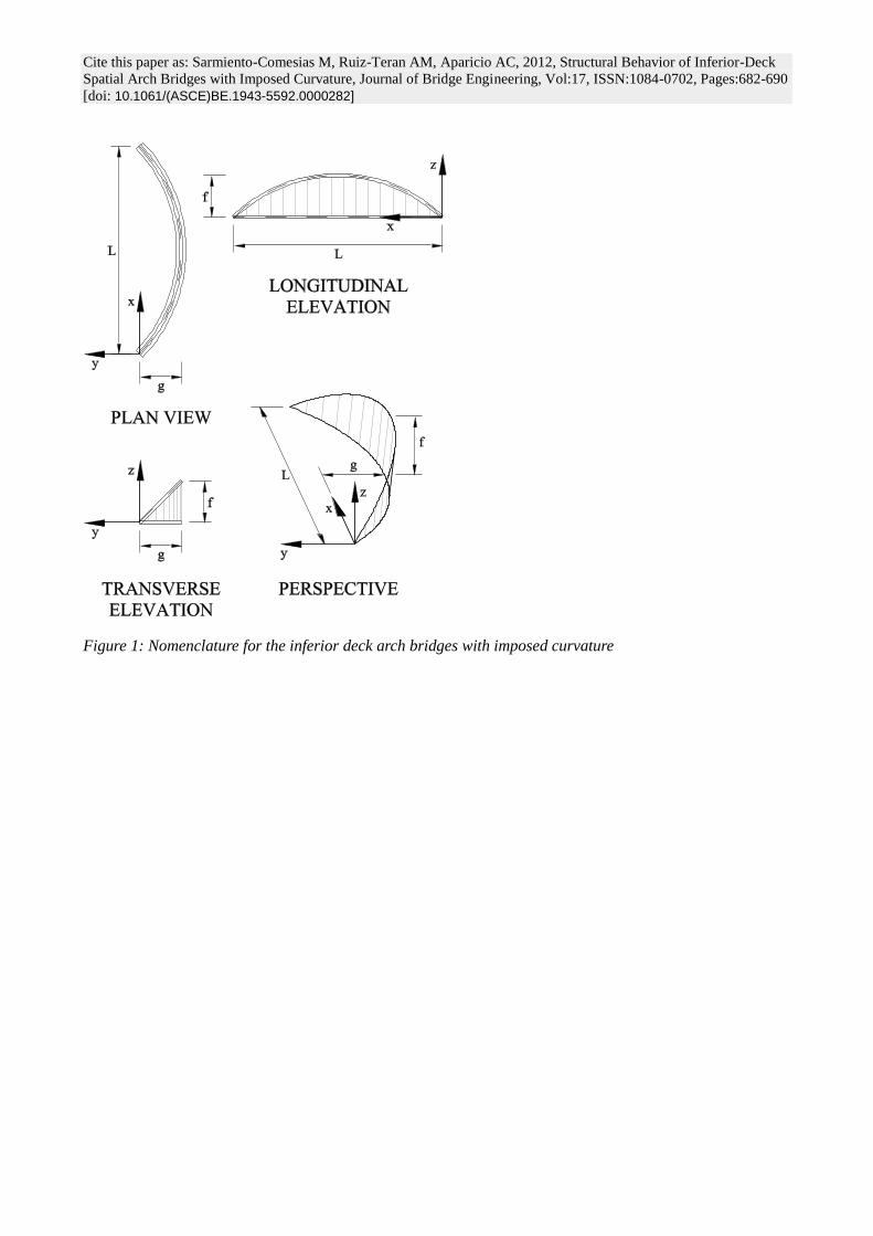
Arch bridges with imposed curvature (ABWIC) are those in which the arches are forced to have the same
curvature in plan as the deck (Figure 1). Therefore, the arch and deck centroid lines are contained in the same
vertical cylinder. In inferior-deck ABWIC (IDABWIC), the deck is located under the arch and supported by
vertical hangers which do not restrict the vertical clearance (Jorquera 2007; Sarmiento et al 2010).
Research procedure and parameters considered
In order to understand the structural behaviour of these arch bridges, a series of 3D frame FE models have
been developed and analyzed (using SAP2000 v14.2), as part of a set of thorough parametric analyses
(Figure 1, model perspective). Several parameters, such as the arch geometrical definition, the deck and arch
curvature in plan view (measured by means of the horizontal sag (g)), the arch rise (f) (Figure 1), the cross-
sectional area and the rigidities of the arch, have been considered. In addition, considering the relevance of
the arch and deck interaction, the cross-sectional rigidities of the deck and the hangers, as well as the link
connections between these structural members, are essential parameters to be investigated. One of the
objectives of this study is to identify the set of these parameters for which the arch works mainly in
Cite this paper as: Sarmiento-Comesias M, Ruiz-Teran AM, Aparicio AC, 2012, Structural Behavior of Inferior-Deck
Spatial Arch Bridges with Imposed Curvature, Journal of Bridge Engineering, Vol:17, ISSN:1084-0702, Pages:682-690
[doi: 10.1061/(ASCE)BE.1943-5592.0000282]
compression (i.e. the arch tends to the anti-funicular of the loading).
For all the analyses presented in this paper, the following dimensions have been employed: span length
L=100m and arch rise f=20m. Unless otherwise mentioned, the variable g is set of 20m. The arch-rise span
ratio (f/L) has been adopted equal to 1/5, as is usual in conventional arch bridges (O’Connor 1971). The plan
curvature effects have been enhanced by making g=f.
All the arches included in these analyses are made of steel, as are most of the built spatial arch bridges.
The arches in each of the studied models are fixed to the deck, which is itself fixed to the abutments.
The behaviour of this bridge type is studied under vertical live loads. The dead loads and the pretension of
the hangers counterbalance each other and need not be considered.
Background and objectives
A considerable number of spatial arch bridges have already been built, but only a few of these have imposed
curvature. Not much research has been done on spatial bridges so far, and even less on IDABWIC (Jorquera
2007). Therefore, there are hardly any references available.
The first spatial arch bridge to be built was Ziggenbach Bridge (1924). It is a planar vertical arch with a
curved superior deck. The first bridge with an arch curved in plan was the Bohlbach Bridge (1932) and the
first one with imposed curvature was the Schwandwach Bridge (1933). All these bridges are deck-stiffened
arch bridges designed by Robert Maillart in Switzerland (Billington 1979, Laffranchi and Marti 1997).
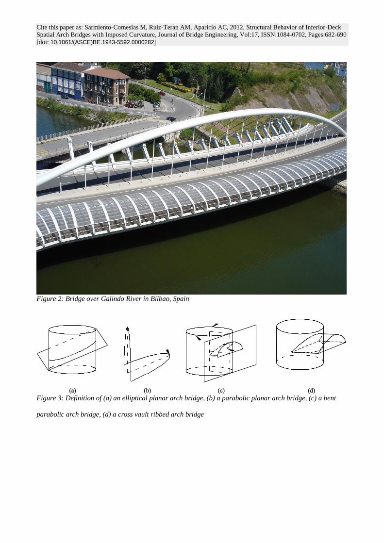
Bridges design did not revert to Maillart’s first arch bridge with imposed curvature until Manterola used this
type in the Endarlatsa Bridge and the Contreras Bridge, and reconfigured it with inferior deck and a double
hanger system in the bridge over the Galindo River in Bilbao (Figure 2; Manterola et al, 2011).
This bridge type is subjected to large bending moments and torsions and the axial forces are smaller than
expected. High curvatures in plan are characterised by an important ‘balcony-beam’ behaviour (ie: out of
plane behaviour of the arch, equivalent to a curved in plan beam with fixed supports loaded perpendicularly).
The arch behaviour improves when employing mechanisms that increase the horizontal stiffness of the
system (Laffranchi and Marti 1997, Jorquera 2007 and 2009, Manterola et al 2009). Until now, this effect has
been justified by the presence of coupled horizontal forces (Jorquera 2007, Manterola et al 2009). However,
the different arch geometrical possibilities and the influence on the structural behaviour of the axial, flexural
Cite this paper as: Sarmiento-Comesias M, Ruiz-Teran AM, Aparicio AC, 2012, Structural Behavior of Inferior-Deck
Spatial Arch Bridges with Imposed Curvature, Journal of Bridge Engineering, Vol:17, ISSN:1084-0702, Pages:682-690
[doi: 10.1061/(ASCE)BE.1943-5592.0000282]
and torsional rigidities of the individual structural members have not been studied yet.
This paper focuses on IDABWIC and intends to:
Define possible geometries for imposed curvature arch bridges and study if non-planar geometries
can be approximated by equivalent arches contained in an inclined plane.
Establish which geometrical and mechanical variables influence the structural behaviour of these
arch bridges.
Find out which is the best way to control the arch behaviour, either with rigid arches or a rigid
hanger-deck system and establish whether it is possible to define an anti-funicular configuration.
Therefore, the main original contributions of this paper are the following:
Different geometrical definitions for spatial arch bridges are given, analyzed and compared.
Clear conceptual models are theoretically and analytically described.
The arch-deck interaction is enhanced by employing rigid hangers. The influence of the hangers’
connection type and the rigidities of the hangers, the deck and the arch is parametrically studied.
Geometrical definition of inferior-deck arch bridges with imposed curvature (IDABWIC)
The different ways of defining IDABWIC arches (Sarmiento et al 2010) are summarized in Figure 3.
Depending on how the arch is defined it might be contained in a plane or not. In particular, bent parabolic
arch bridges (Figure 3c) have non-planar arches and cross vault ribbed arch bridges (formed by the
intersection of two cylinders, Figure 3d) are non-planar unless both cylinders have the same diameter and
coincident axes.
Given a plan alignment for the deck, in a similar way as for the latter example, a non-planar arch with
imposed curvature may be obtained by the intersection of a vertical cylinder containing the deck and a three-
dimensional body, such as an ellipsoid, elliptic paraboloid, hyperbolic paraboloid, hyperboloid, cone or torus.
A parametric study (Sarmiento et al 2010), which compares the behaviour of the FE frame models of (1) an
elliptical planar arch bridge, (2) a bent parabolic arch bridge, and (3) a cross vault ribbed arch bridge, proves
that non-planar arches with imposed curvature can be approximated by planar arches with imposed curvature
and identical rises, with differences in internal forces and displacements smaller than 1,75% for uniform
Cite this paper as: Sarmiento-Comesias M, Ruiz-Teran AM, Aparicio AC, 2012, Structural Behavior of Inferior-Deck
Spatial Arch Bridges with Imposed Curvature, Journal of Bridge Engineering, Vol:17, ISSN:1084-0702, Pages:682-690
[doi: 10.1061/(ASCE)BE.1943-5592.0000282]
distributed loading, and 2% for asymmetrical loading on half the length of the deck for f/g≤1. This
conclusion is very powerful, allowing us to refer to in-plane and out-of-plane behaviour even for non-planar
arches.
Structural behaviour of IDABWIC
Understanding the effect of increasing the horizontal sag
The structural response of an arch bridge with imposed curvature, L=100m, f=20m, and g varying from 0 to
10m is compared with a conventional vertical (g=0) arch bridge having identical rise and span length. The
comparison provides a first appropriate approach to this research. The arch has a circular hollow section
(CHS), with D=1000mm and t=30mm, the deck is a box girder 4000x800mm and t=15mm, and the hangers
are flexible stay cables.
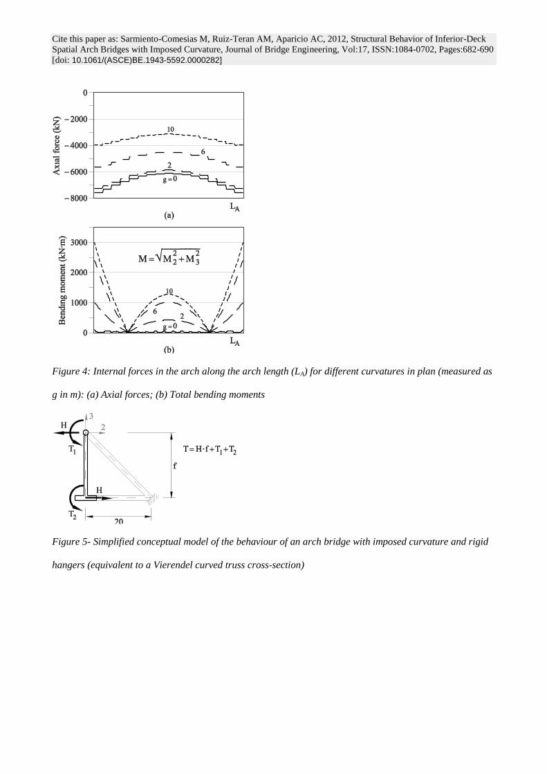
For a given vertical rise, the analysis shows that a higher arch plan curvature leads to (Figure 4):
smaller axial forces in the arch
larger total bending moments in the arch (both in-plane and out of plane bending moments increase)
larger in-plane and out of plane shear forces and larger torsional moments in the arch
This had been observed also by Jorquera (2007).
When increasing the plan curvature, the plane of the arch inclines. This causes the described changes in the
internal forces of the arch, because the ‘arch behaviour’ in the plane of the arch decreases and the ‘balcony-
beam behaviour’ of the arch is enhanced.
General scope
Conceptual models
When employing rigid hangers fixed to both the arch and deck, the system may behave like a curved
Vierendel truss. The structural response of this balcony-beam under a vertical load leads to both bending and
torsional moments. The resultant response torque will be resisted by the sum of St Venant torsion at both the
arch and the deck (Figure 5, T1 and T2 respectively) and warping torsion (Figure 5, H·f). The distribution
between the two torsion types depends on both the transverse flexural rigidity (I3-3) and the torsional rigidity
(J1) of the arch, and on the torsional rigidity of the deck (J2).
Horizontal forces, H, produce tension forces in the arch, diminishing the axial compression. These H forces
Cite this paper as: Sarmiento-Comesias M, Ruiz-Teran AM, Aparicio AC, 2012, Structural Behavior of Inferior-Deck
Spatial Arch Bridges with Imposed Curvature, Journal of Bridge Engineering, Vol:17, ISSN:1084-0702, Pages:682-690
[doi: 10.1061/(ASCE)BE.1943-5592.0000282]
increase the out-of-plane forces in the arch too. Therefore, it is of interest to reduce them. To do so, we need
to decrease the warping torsion. By increasing the torsional stiffness of the deck (high J2) and an arch with a
low J1 and I3-3, torques will be mainly resisted by the deck’s StVenant torsional component. Therefore, H
will tend to zero and no tensions will be introduced on the arch. On the other hand, employing low J1 and J2
values, leads to T1≈0; T2≈0 and T = H·f. Consequently, the axial forces in the arch diminish greatly.
This behaviour can be intuitively deduced, but the real behaviour is too complex to develop a simple
analytical model. Consequently, we will study these cases with a FE analysis of full bridges.
On the other hand, if we employ flexible or pinned hangers, the curved Vierendel truss analogy is no longer
possible. The system behaves like two balcony beams vertically connected by the hangers.
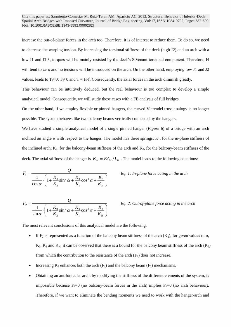
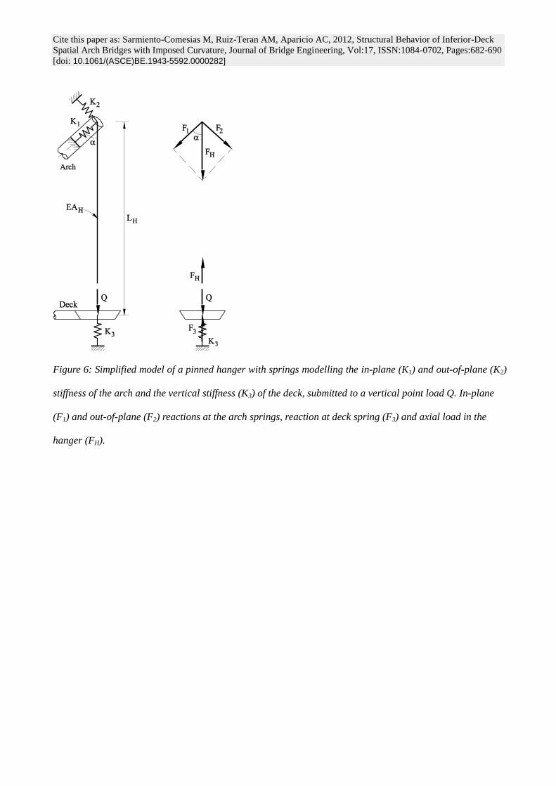
We have studied a simple analytical model of a single pinned hanger (Figure 6) of a bridge with an arch
inclined an angle α with respect to the hanger. The model has three springs: K1, for the in-plane stiffness of
the inclined arch; K2, for the balcony-beam stiffness of the arch and K3, for the balcony-beam stiffness of the
deck. The axial stiffness of the hanger is H H HK EA L . The model leads to the following equations:
1
2 23 3 3
2 1
11 sin cos
cos H
QF
K K K
K K K
Eq. 1: In-plane force acting in the arch
2
2 23 3 3
2 1
11 sin cos
sin H
QF
K K K
K K K
Eq. 2: Out-of-plane force acting in the arch
The most relevant conclusions of this analytical model are the following:
If F2 is represented as a function of the balcony beam stiffness of the arch (K2), for given values of α,
K3, K1 and KH, it can be observed that there is a bound for the balcony beam stiffness of the arch (K2)
from which the contribution to the resistance of the arch (F2) does not increase.
Increasing K2 enhances both the arch (F1) and the balcony beam (F2) mechanisms.
Obtaining an antifunicular arch, by modifying the stiffness of the different elements of the system, is
impossible because F2=0 (no balcony-beam forces in the arch) implies F1=0 (no arch behaviour).
Therefore, if we want to eliminate the bending moments we need to work with the hanger-arch and
Cite this paper as: Sarmiento-Comesias M, Ruiz-Teran AM, Aparicio AC, 2012, Structural Behavior of Inferior-Deck
Spatial Arch Bridges with Imposed Curvature, Journal of Bridge Engineering, Vol:17, ISSN:1084-0702, Pages:682-690
[doi: 10.1061/(ASCE)BE.1943-5592.0000282]
hanger-deck joint connections or to employ an additional external system (such as the stay cables in
Galindo Bridge, Figure 2) which prevents out-of-plane displacements in the arch.
We should note that, in reality, the systems will not be as simple as the models described before, since (1) the
distribution of internal forces depends on the arch and deck individual behaviour (2) the hangers have
different length and stiffness along the bridge and therefore transmit different forces.
Frame FE models of IDABWIC with rigid hangers
We have done linear parametric analyses with a frame FE model of the whole arch bridge with L=100m;
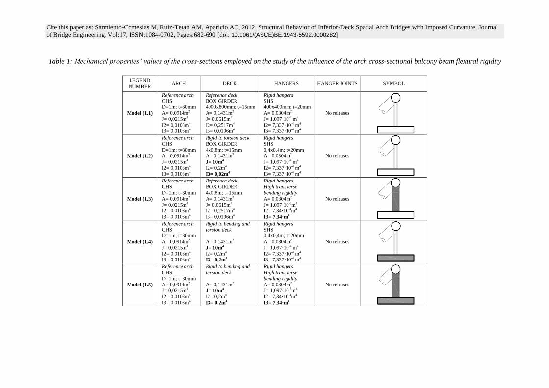
f=20m and g=20m. The parameters studied are shown in Tables 1 and 2. The arch is fixed to the deck, which
is itself fixed to the abutments.
Structural behaviour under a vertical uniform distributed loading applied on the whole deck
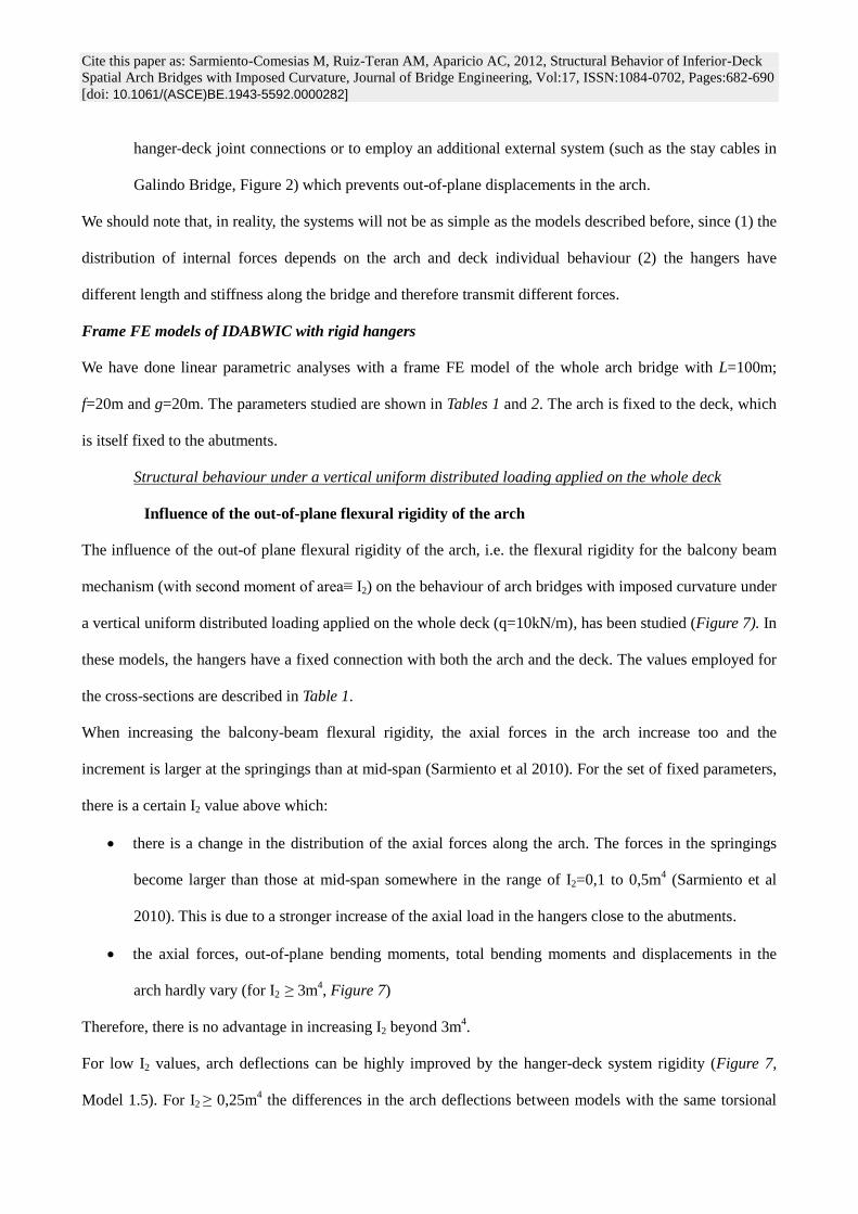
Influence of the out-of-plane flexural rigidity of the arch
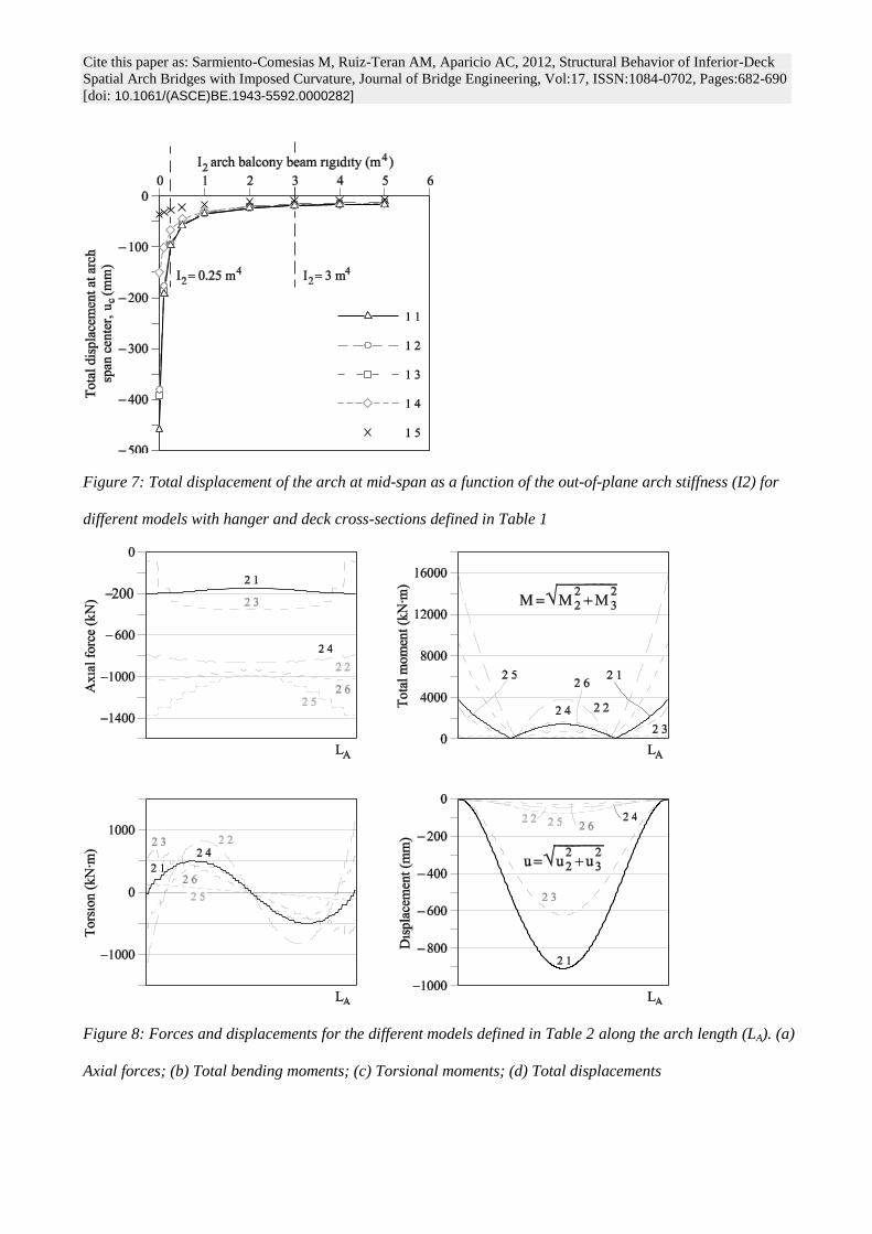
The influence of the out-of plane flexural rigidity of the arch, i.e. the flexural rigidity for the balcony beam
mechanism (with second moment of area≡ I2) on the behaviour of arch bridges with imposed curvature under
a vertical uniform distributed loading applied on the whole deck (q=10kN/m), has been studied (Figure 7). In
these models, the hangers have a fixed connection with both the arch and the deck. The values employed for
the cross-sections are described in Table 1.
When increasing the balcony-beam flexural rigidity, the axial forces in the arch increase too and the
increment is larger at the springings than at mid-span (Sarmiento et al 2010). For the set of fixed parameters,
there is a certain I2 value above which:
there is a change in the distribution of the axial forces along the arch. The forces in the springings
become larger than those at mid-span somewhere in the range of I2=0,1 to 0,5m4 (Sarmiento et al
2010). This is due to a stronger increase of the axial load in the hangers close to the abutments.
the axial forces, out-of-plane bending moments, total bending moments and displacements in the
arch hardly vary (for I2 ≥ 3m4, Figure 7)
Therefore, there is no advantage in increasing I2 beyond 3m4.
For low I2 values, arch deflections can be highly improved by the hanger-deck system rigidity (Figure 7,
Model 1.5). For I2 ≥ 0,25m4 the differences in the arch deflections between models with the same torsional
Cite this paper as: Sarmiento-Comesias M, Ruiz-Teran AM, Aparicio AC, 2012, Structural Behavior of Inferior-Deck
Spatial Arch Bridges with Imposed Curvature, Journal of Bridge Engineering, Vol:17, ISSN:1084-0702, Pages:682-690
[doi: 10.1061/(ASCE)BE.1943-5592.0000282]
rigidity of the deck and different flexural rigidity of the deck are smaller than 3,4%.
We can conclude that the out-of-plane flexural rigidity of the arch (I2), controls very efficiently the arch
deflections. In fact, the arch deflections remain steady when I2 ≥ 3m4 (for our f=g=20m and L=100m model),
regardless the value of the rest of the parameters (Figure 7, all models).
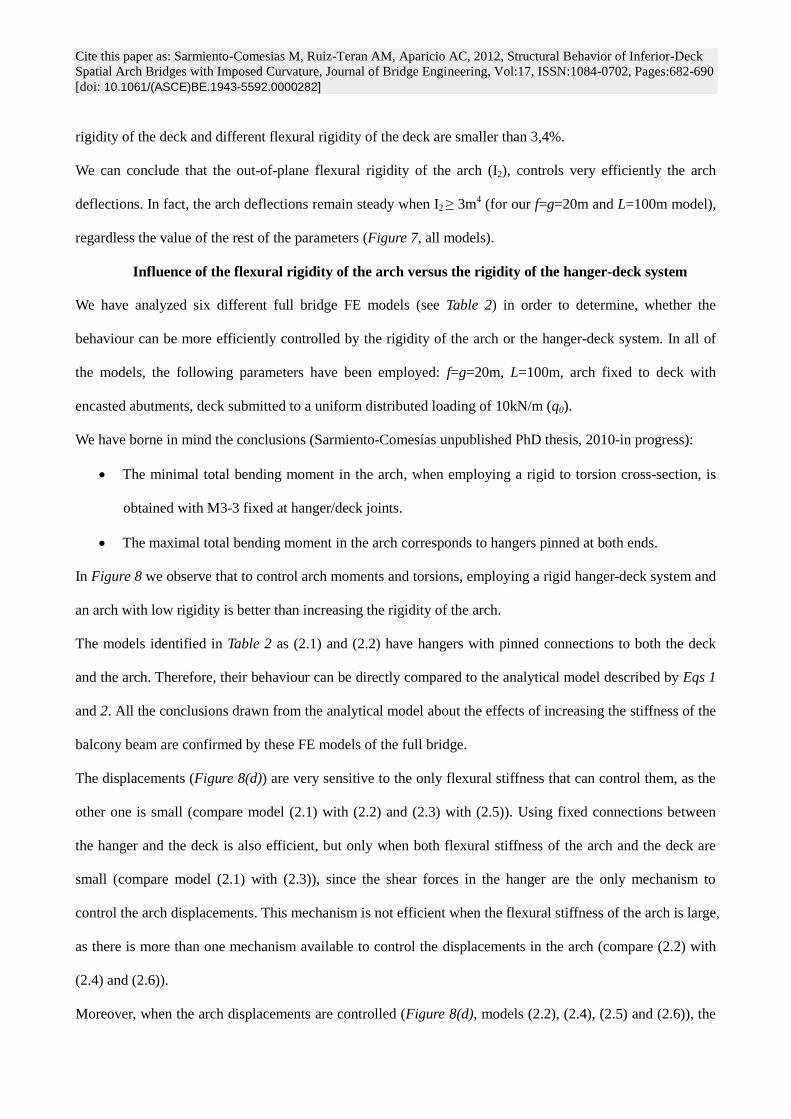
Influence of the flexural rigidity of the arch versus the rigidity of the hanger-deck system
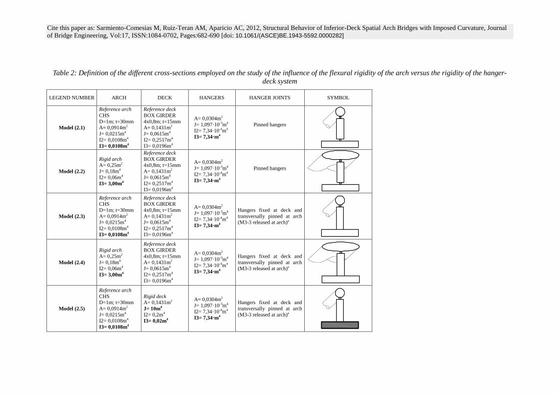
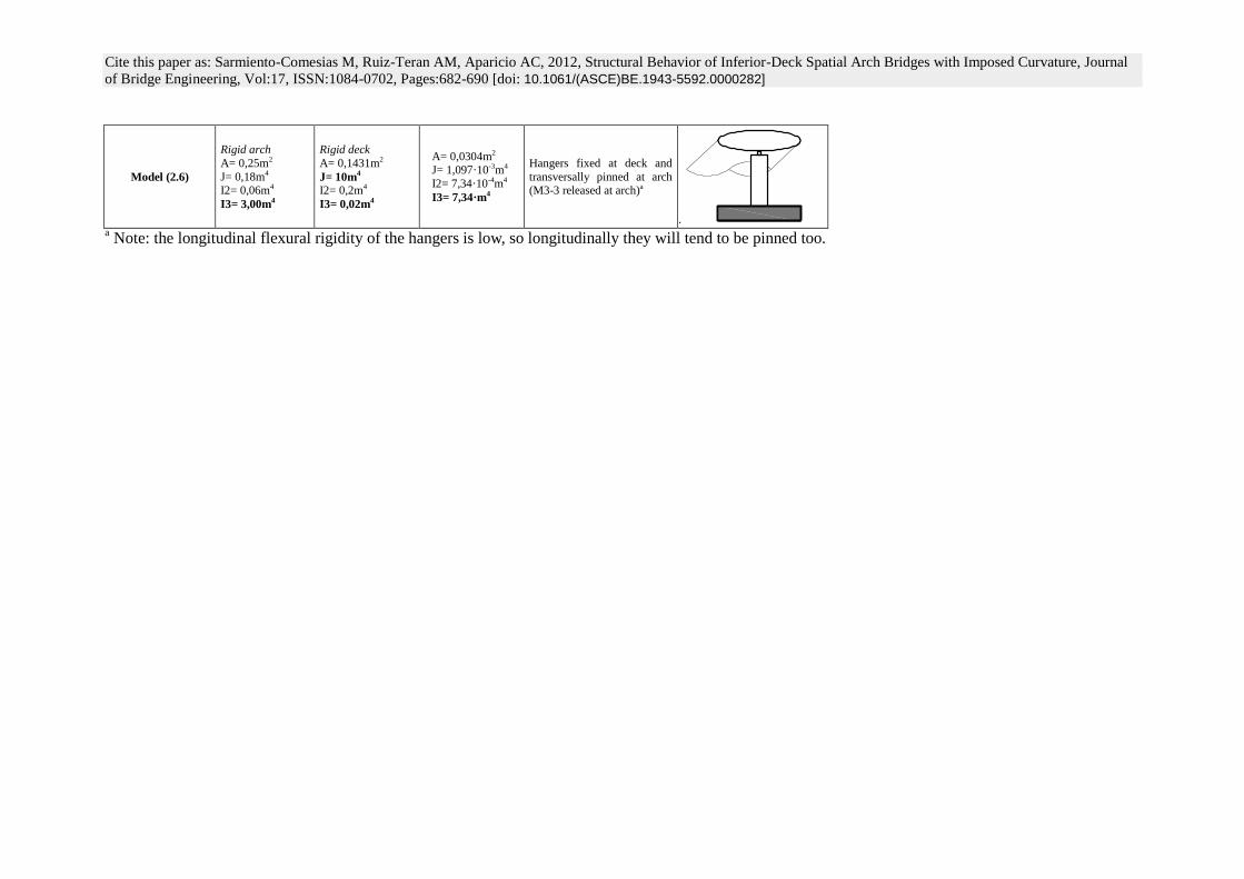
We have analyzed six different full bridge FE models (see Table 2) in order to determine, whether the
behaviour can be more efficiently controlled by the rigidity of the arch or the hanger-deck system. In all of
the models, the following parameters have been employed: f=g=20m, L=100m, arch fixed to deck with
encasted abutments, deck submitted to a uniform distributed loading of 10kN/m (q0).
We have borne in mind the conclusions (Sarmiento-Comesías unpublished PhD thesis, 2010-in progress):
The minimal total bending moment in the arch, when employing a rigid to torsion cross-section, is
obtained with M3-3 fixed at hanger/deck joints.
The maximal total bending moment in the arch corresponds to hangers pinned at both ends.
In Figure 8 we observe that to control arch moments and torsions, employing a rigid hanger-deck system and
an arch with low rigidity is better than increasing the rigidity of the arch.
The models identified in Table 2 as (2.1) and (2.2) have hangers with pinned connections to both the deck
and the arch. Therefore, their behaviour can be directly compared to the analytical model described by Eqs 1
and 2. All the conclusions drawn from the analytical model about the effects of increasing the stiffness of the
balcony beam are confirmed by these FE models of the full bridge.
The displacements (Figure 8(d)) are very sensitive to the only flexural stiffness that can control them, as the
other one is small (compare model (2.1) with (2.2) and (2.3) with (2.5)). Using fixed connections between
the hanger and the deck is also efficient, but only when both flexural stiffness of the arch and the deck are
small (compare model (2.1) with (2.3)), since the shear forces in the hanger are the only mechanism to
control the arch displacements. This mechanism is not efficient when the flexural stiffness of the arch is large,
as there is more than one mechanism available to control the displacements in the arch (compare (2.2) with
(2.4) and (2.6)).
Moreover, when the arch displacements are controlled (Figure 8(d), models (2.2), (2.4), (2.5) and (2.6)), the
Cite this paper as: Sarmiento-Comesias M, Ruiz-Teran AM, Aparicio AC, 2012, Structural Behavior of Inferior-Deck
Spatial Arch Bridges with Imposed Curvature, Journal of Bridge Engineering, Vol:17, ISSN:1084-0702, Pages:682-690
[doi: 10.1061/(ASCE)BE.1943-5592.0000282]
arch behaviour is enhanced (Figure 8(a), models (2.2), (2.4), (2.5) and (2.6)). However, when the
displacements are controlled by means of the flexural stiffness of the arch (Figure 8(d), models (2.2), (2.4),
and (2.6)), the bending moments in the arch are large (Figure 8(b), models (2.2), (2.4), and (2.6)). This effect
is enhanced, when the flexural stiffness of the arch is the only parameter that is available to control the
displacements in the arch (model (2.2) in Figures 8(b) and (d)). Therefore, the arch displacements are best
controlled by providing rigidity to the whole system. However, controlling the arch displacements while
enhancing the arch behaviour, is achieved by providing rigidity only to the hanger-deck system (model (2.5),
Figure 8(a) to (d)).
It is possible to define a set of parameters (Table 2, model (2.5)) for which the arch tends to the antifunicular
of the loading. This behaviour is achieved when the hanger has a fixed connection to the deck in the
transverse direction, the torsional rigidity of the deck is large, and the flexural rigidity of the arch is small.
Therefore, opposite to what has been concluded in other studies (Jorquera 2007), antifunicular arches do
exist for IDABWIC.
A geometrically non-linear analysis (P-delta and large displacements according to SAP2000 reference
manual) has been done for model (2.5). For a linear analysis we have obtained 21,8mm in-plane
displacements and 71,9mm out-of-plane displacements at the arch crown. The values of the non-linear
analysis are very close, being 22,0 and 72,0mm respectively. The internal forces obtained for linear and non-
linear analysis have very similar values too (M. Sarmiento-Comesías, unpublished PhD thesis, 2010-in
progress). Therefore, if the hanger-deck system is rigid enough, non-geometrical effects are negligible.
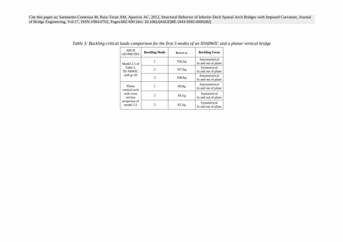
The buckling loads and modes for model (2.5) have also been analyzed and compared to those of a classical
vertical bridge with the same cross-sectional properties (Table 3). It is proved that the critical buckling load
for a spatial arch bridge is much higher than for a planar vertical bridge, because the arch takes lower axial
forces.
We would like to stress that the parameters that we propose in order to define antifunicular IDABWIC are
exactly the same as those that Robert Maillart used for his superior deck curved arch bridges, with a
foresight that only a genius could have, although he did not prove it through calculations (Billington 1997,
Laffranchi and Marti 1997). We end, therefore, at the intuitive start of our paper, back to the origins of spatial
Cite this paper as: Sarmiento-Comesias M, Ruiz-Teran AM, Aparicio AC, 2012, Structural Behavior of Inferior-Deck
Spatial Arch Bridges with Imposed Curvature, Journal of Bridge Engineering, Vol:17, ISSN:1084-0702, Pages:682-690
[doi: 10.1061/(ASCE)BE.1943-5592.0000282]
arch bridges.
Structural behaviour under non-symmetrical vertical loading
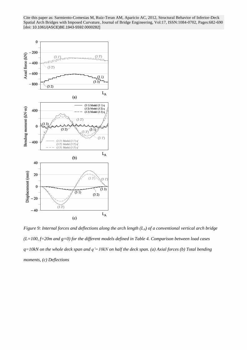
For conventional vertical arch bridges (g=0, Figure 9), the maximal arch shear forces, bending moments and
deflections are significantly higher when the loading is applied on half the deck span (from the abutment to
the mid-span (q’=10kN/m)) than on the whole deck span (q=10kN/m). However, the higher axial forces are
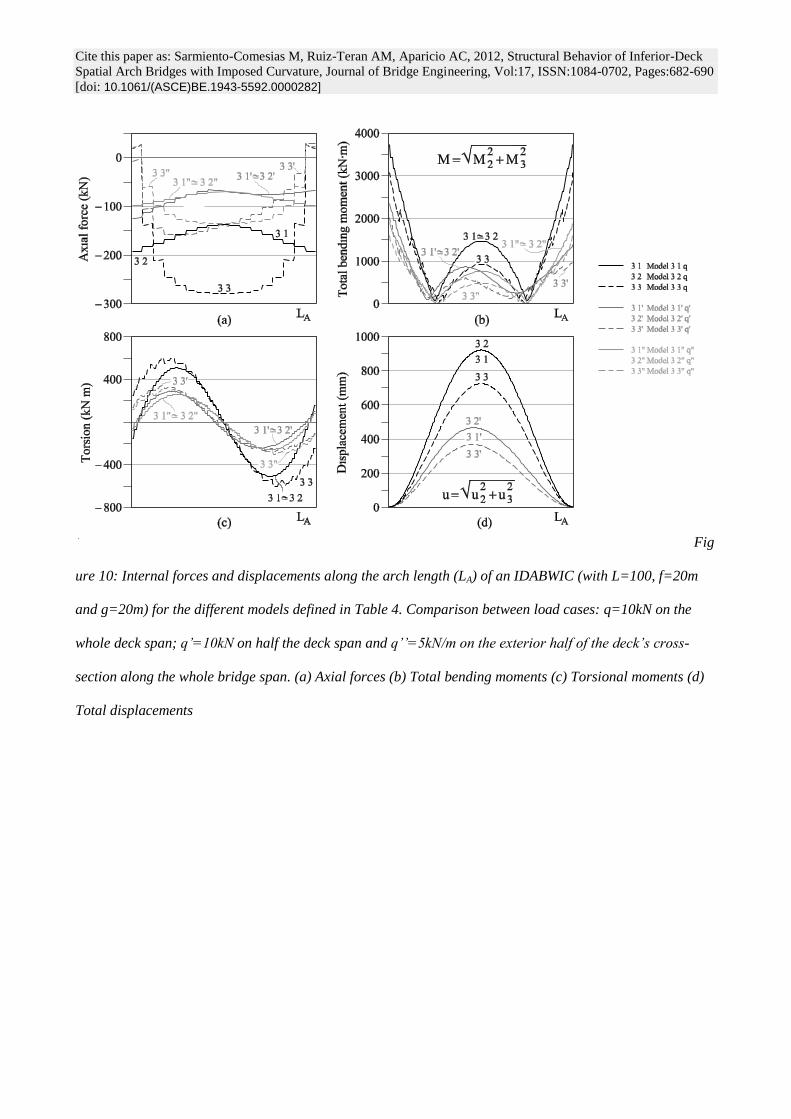
obtained when the whole deck span is fully loaded (q=10kN/m). On the contrary, for IDABWIC (with a large
g/f ratio), the critical load case, for both internal forces and displacements, is obtained when the uniform
distributed loading is applied on the whole deck span (Figure 10).
A vertical uniform distributed loading applied on the exterior half of the deck’s cross-section along the whole
bridge span (q’’=5kN/m; t’’=5kN·m/m, ie: vertical loading and tipping torque) has also been analyzed, given
the importance of torsional behaviour in this bridge type. For all the models it is proven that internal forces
are mainly due to vertical loading.
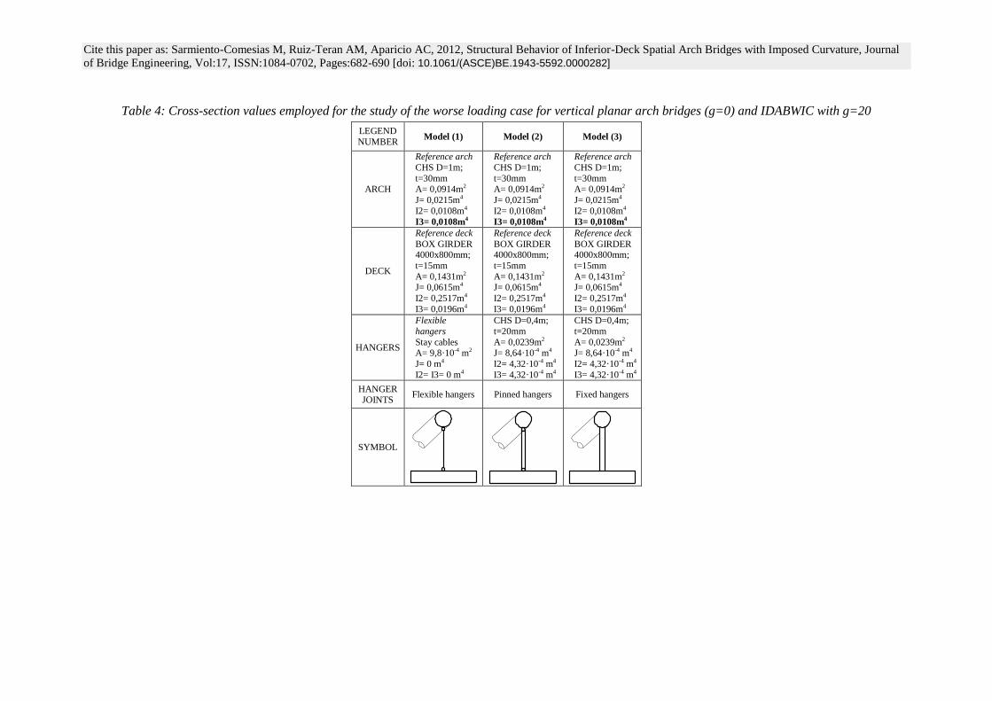
All these conclusions are verified both for flexible and rigid hangers (see Table 4). For all the loading cases,
models 3.1 and 3.2 have very similar results as expected.
Conclusions
In the context of the present study, we can conclude:
Non-planar arches with imposed curvature can be approximated with negligible errors by inclined
planar arches with imposed curvature with the same rise.
There is a value for the out-of-plane arch rigidity for which the distribution of axial forces along the
arch changes, tending to concentrate either at mid-span or at springings, and also a bound for which
the internal forces and deflections converge. Increasing the balcony beam rigidity above this bound
has no advantage at all.
Given a vertical rise of the arch, and employing pinned hangers, the higher the plan curvature, the
lower the axial forces and the higher the moments in the arch.
Employing a rigid hanger-deck system (deck with high torsional rigidity and hangers with high
transverse flexural rigidity) and an arch with low flexural rigidity is more efficient to enhance the
arch behaviour in IDABWIC than increasing the rigidity of the arch. This ‘ideal configuration’ is the
Cite this paper as: Sarmiento-Comesias M, Ruiz-Teran AM, Aparicio AC, 2012, Structural Behavior of Inferior-Deck
Spatial Arch Bridges with Imposed Curvature, Journal of Bridge Engineering, Vol:17, ISSN:1084-0702, Pages:682-690
[doi: 10.1061/(ASCE)BE.1943-5592.0000282]
simplest way to make the arch tend to its anti-funicular form.
If the hanger-deck system is rigid enough, as in the described ‘ideal configuration’, geometrically
non-linear effects are negligible.
The critical buckling load for an IDABWIC with the ‘ideal configuration’ is much higher than that of
a planar vertical bridge, because the arch takes lower axial forces.
For IDABWIC with a large g/f ratio, the critical live load case is obtained when the uniform
distributed loading is applied on the whole deck span, whereas for a conventional vertical arch
bridge (g=0) the maximal arch shear forces, bending moments and deflections are higher for a
uniform distributed loading applied on half the deck span.
Acknowledgements
The authors would like to thank the funding support received by the first author from both the FPU
Scholarships of the Spanish Government and the Catalan Institution of Civil Engineers.
References
Billington, D. P. (1979). “The Role of Science in Engineering: Force Follows Form.” Robert Maillart‘s
bridges. The art of engineering. Princeton, New Jersey: Princeton University Press, 94-105; 111-112.
Billington, D. P. (1997). Robert Maillart. Builder, Designer, and Artist. Cambridge University Press, 146-149;
174-182.
Jorquera, J. J. (2007). “Study of the structural behaviour of spatial arch bridges”, PhD Thesis. Supervised by
Prof. Manterola, Technical University of Madrid (UPM), (in Spanish).
Jorquera, J. J. (2009). “Structural behaviour of spatial arch bridges”, Proc., Int. Symp. 2009 on Evolution and
Trends in Design, Analysis and Construction of Shell and Spatial Structures, IASS, Domingo, A., and Lázaro,
C. (Eds), Valencia, Spain, 2447-2457.
Laffranchi, M., and Marti, P. (1997). “Robert’s Maillart’s concrete arch bridges”, Journal of structural
engineering, 123(10), 1280-1286.
Manterola, J., Gil, M. A., and Muñoz-Rojas, J., (2009). “Arch spatial Bridges over the Galindo and Bidasoa
Rivers”, Cauce 2000: Revista de ingeniería civil, 147, 20-29, (in Spanish).
Manterola, J., Gil, M. A., and Muñoz-Rojas, J., (2011). “Arch spatial Bridges over the Galindo and Bidasoa
Cite this paper as: Sarmiento-Comesias M, Ruiz-Teran AM, Aparicio AC, 2012, Structural Behavior of Inferior-Deck
Spatial Arch Bridges with Imposed Curvature, Journal of Bridge Engineering, Vol:17, ISSN:1084-0702, Pages:682-690
[doi: 10.1061/(ASCE)BE.1943-5592.0000282]
Rivers”, Structural Engineering International, 21 (1). 114-121
O’Connor, C. (1971). “Chapter 10: Arches.” Design of Bridges Superstructuctures, John Wiley and Sons,
New York, USA., 488-544.
Sarmiento-Comesías, M. (2009), MPhil-PhD Transfer report. Jointly supervised by A. C. Aparicio and A.
Ruiz-Teran, Technical University of Catalonia (UPC), Barcelona, Spain (in Spanish)
Sarmiento, M., Ruiz-Teran, A. And Aparicio, A. C. (2010). “Structural response of spatial arches with
imposed Curvature.” Proc., 34th Int. Symp. on Bridge and Structural Engineering, IABSE, Venice, Italy, 1-8
Cite this paper as: Sarmiento-Comesias M, Ruiz-Teran AM, Aparicio AC, 2012, Structural Behavior of Inferior-Deck Spatial Arch Bridges with Imposed Curvature, Journal
of Bridge Engineering, Vol:17, ISSN:1084-0702, Pages:682-690 [doi: 10.1061/(ASCE)BE.1943-5592.0000282]
Table 1: Mechanical properties’ values of the cross-sections employed on the study of the influence of the arch cross-sectional balcony beam flexural rigidity
LEGEND
NUMBER ARCH DECK HANGERS HANGER JOINTS SYMBOL
Model (1.1)
Reference arch CHS
D=1m; t=30mm
A= 0,0914m2
J= 0,0215m4
I2= 0,0108m4
I3= 0,0108m4
Reference deck BOX GIRDER
4000x800mm; t=15mm
A= 0,1431m2
J= 0,0615m4
I2= 0,2517m4
I3= 0,0196m4
Rigid hangers SHS
400x400mm; t=20mm
A= 0,0304m2
J= 1,097·10-4 m4
I2= 7,337·10-4 m4
I3= 7,337·10-4 m4
No releases
Model (1.2)
Reference arch
CHS
D=1m; t=30mm A= 0,0914m2
J= 0,0215m4
I2= 0,0108m4 I3= 0,0108m4
Rigid to torsion deck
BOX GIRDER
4x0,8m; t=15mm A= 0,1431m2
J= 10m4
I2= 0,2m4
I3= 0,02m4
Rigid hangers
SHS
0,4x0,4m; t=20mm A= 0,0304m2
J= 1,097·10-4 m4
I2= 7,337·10-4 m4 I3= 7,337·10-4 m4
No releases
Model (1.3)
Reference arch
CHS
D=1m; t=30mm
A= 0,0914m2
J= 0,0215m4 I2= 0,0108m4
I3= 0,0108m4
Reference deck
BOX GIRDER
4x0,8m; t=15mm
A= 0,1431m2
J= 0,0615m4 I2= 0,2517m4
I3= 0,0196m4
Rigid hangers
High transverse bending rigidity
A= 0,0304m2
J= 1,097·10-3m4 I2= 7,34·10-4m4
I3= 7,34·m4
No releases
Model (1.4)
Reference arch CHS
D=1m; t=30mm
A= 0,0914m2 J= 0,0215m4
I2= 0,0108m4
I3= 0,0108m4
Rigid to bending and torsion deck
A= 0,1431m2
J= 10m4
I2= 0,2m4
I3= 0,2m4
Rigid hangers SHS
0,4x0,4m; t=20mm
A= 0,0304m2 J= 1,097·10-4 m4
I2= 7,337·10-4 m4
I3= 7,337·10-4 m4
No releases
Model (1.5)
Reference arch
CHS D=1m; t=30mm
A= 0,0914m2
J= 0,0215m4 I2= 0,0108m4
I3= 0,0108m4
Rigid to bending and
torsion deck
A= 0,1431m2
J= 10m4
I2= 0,2m4
I3= 0,2m4
Rigid hangers
High transverse bending rigidity
A= 0,0304m2
J= 1,097·10-3m4 I2= 7,34·10-4m4
I3= 7,34·m4
No releases
Cite this paper as: Sarmiento-Comesias M, Ruiz-Teran AM, Aparicio AC, 2012, Structural Behavior of Inferior-Deck Spatial Arch Bridges with Imposed Curvature, Journal
of Bridge Engineering, Vol:17, ISSN:1084-0702, Pages:682-690 [doi: 10.1061/(ASCE)BE.1943-5592.0000282]
Table 2: Definition of the different cross-sections employed on the study of the influence of the flexural rigidity of the arch versus the rigidity of the hanger-
deck system
LEGEND NUMBER ARCH DECK HANGERS HANGER JOINTS SYMBOL
Model (2.1)
Reference arch
CHS
D=1m; t=30mm A= 0,0914m2
J= 0,0215m4
I2= 0,0108m4
I3= 0,0108m4
Reference deck
BOX GIRDER
4x0,8m; t=15mm A= 0,1431m2
J= 0,0615m4
I2= 0,2517m4 I3= 0,0196m4
A= 0,0304m2
J= 1,097·10-3m4
I2= 7,34·10-4m4
I3= 7,34·m4
Pinned hangers
Model (2.2)
Rigid arch A= 0,25m2
J= 0,18m4
I2= 0,06m4
I3= 3,00m4
Reference deck
BOX GIRDER 4x0,8m; t=15mm
A= 0,1431m2
J= 0,0615m4 I2= 0,2517m4
I3= 0,0196m4
A= 0,0304m2
J= 1,097·10-3m4 I2= 7,34·10-4m4
I3= 7,34·m4
Pinned hangers
Model (2.3)
Reference arch CHS
D=1m; t=30mm
A= 0,0914m2 J= 0,0215m4
I2= 0,0108m4
I3= 0,0108m4
Reference deck BOX GIRDER
4x0,8m; t=15mm
A= 0,1431m2 J= 0,0615m4
I2= 0,2517m4 I3= 0,0196m4
A= 0,0304m2 J= 1,097·10-3m4
I2= 7,34·10-4m4
I3= 7,34·m4
Hangers fixed at deck and
transversally pinned at arch
(M3-3 released at arch)a
Model (2.4)
Rigid arch
A= 0,25m2
J= 0,18m4 I2= 0,06m4
I3= 3,00m4
Reference deck BOX GIRDER
4x0,8m; t=15mm
A= 0,1431m2 J= 0,0615m4
I2= 0,2517m4
I3= 0,0196m4
A= 0,0304m2 J= 1,097·10-3m4
I2= 7,34·10-4m4
I3= 7,34·m4
Hangers fixed at deck and
transversally pinned at arch
(M3-3 released at arch)a
Model (2.5)
Reference arch
CHS D=1m; t=30mm
A= 0,0914m2
J= 0,0215m4 I2= 0,0108m4
I3= 0,0108m4
Rigid deck A= 0,1431m2
J= 10m4
I2= 0,2m4
I3= 0,02m4
A= 0,0304m2
J= 1,097·10-3m4 I2= 7,34·10-4m4
I3= 7,34·m4
Hangers fixed at deck and
transversally pinned at arch
(M3-3 released at arch)a
Cite this paper as: Sarmiento-Comesias M, Ruiz-Teran AM, Aparicio AC, 2012, Structural Behavior of Inferior-Deck Spatial Arch Bridges with Imposed Curvature, Journal
of Bridge Engineering, Vol:17, ISSN:1084-0702, Pages:682-690 [doi: 10.1061/(ASCE)BE.1943-5592.0000282]
Model (2.6)
Rigid arch
A= 0,25m2
J= 0,18m4 I2= 0,06m4
I3= 3,00m4
Rigid deck
A= 0,1431m2
J= 10m4
I2= 0,2m4
I3= 0,02m4
A= 0,0304m2 J= 1,097·10-3m4
I2= 7,34·10-4m4
I3= 7,34·m4
Hangers fixed at deck and
transversally pinned at arch
(M3-3 released at arch)a
. a Note: the longitudinal flexural rigidity of the hangers is low, so longitudinally they will tend to be pinned too.
Cite this paper as: Sarmiento-Comesias M, Ruiz-Teran AM, Aparicio AC, 2012, Structural Behavior of Inferior-Deck Spatial Arch Bridges with Imposed Curvature, Journal
of Bridge Engineering, Vol:17, ISSN:1084-0702, Pages:682-690 [doi: 10.1061/(ASCE)BE.1943-5592.0000282]
Table 3: Buckling critical loads comparison for the first 3 modes of an IDABWIC and a planar vertical bridge
ARCH GEOMETRY
Buckling Mode qCRITICAL Buckling Form
Model 2.5 of Table 2.
ID-ABWIC
with g=20
1 166,2q0 Antymmetrical
In and out of plane
2 167,9q0 Symmetrical
In and out of plane
3 168,8q0 Antymmetrical
In and out of plane
Planar
vertical arch
with cross section
properties of
model 2.5
1 38,9q0 Antymmetrical
In and out of plane
2 39,1q0 Symmetrical
In and out of plane
3 82,2q0 Symmetrical
In and out of plane
Cite this paper as: Sarmiento-Comesias M, Ruiz-Teran AM, Aparicio AC, 2012, Structural Behavior of Inferior-Deck Spatial Arch Bridges with Imposed Curvature, Journal
of Bridge Engineering, Vol:17, ISSN:1084-0702, Pages:682-690 [doi: 10.1061/(ASCE)BE.1943-5592.0000282]
Table 4: Cross-section values employed for the study of the worse loading case for vertical planar arch bridges (g=0) and IDABWIC with g=20
LEGEND
NUMBER Model (1) Model (2) Model (3)
ARCH
Reference arch
CHS D=1m;
t=30mm A= 0,0914m2
J= 0,0215m4
I2= 0,0108m4
I3= 0,0108m4
Reference arch
CHS D=1m;
t=30mm A= 0,0914m2
J= 0,0215m4
I2= 0,0108m4
I3= 0,0108m4
Reference arch
CHS D=1m;
t=30mm A= 0,0914m2
J= 0,0215m4
I2= 0,0108m4
I3= 0,0108m4
DECK
Reference deck
BOX GIRDER 4000x800mm;
t=15mm
A= 0,1431m2 J= 0,0615m4
I2= 0,2517m4
I3= 0,0196m4
Reference deck
BOX GIRDER 4000x800mm;
t=15mm
A= 0,1431m2 J= 0,0615m4
I2= 0,2517m4
I3= 0,0196m4
Reference deck
BOX GIRDER 4000x800mm;
t=15mm
A= 0,1431m2 J= 0,0615m4
I2= 0,2517m4
I3= 0,0196m4
HANGERS
Flexible
hangers
Stay cables
A= 9,8·10-4 m2
J= 0 m4
I2= I3= 0 m4
CHS D=0,4m;
t=20mm
A= 0,0239m2
J= 8,64·10-4 m4
I2= 4,32·10-4 m4
I3= 4,32·10-4 m4
CHS D=0,4m;
t=20mm
A= 0,0239m2
J= 8,64·10-4 m4
I2= 4,32·10-4 m4
I3= 4,32·10-4 m4
HANGER JOINTS
Flexible hangers Pinned hangers Fixed hangers
SYMBOL
Cite this paper as: Sarmiento-Comesias M, Ruiz-Teran AM, Aparicio AC, 2012, Structural Behavior of Inferior-Deck
Spatial Arch Bridges with Imposed Curvature, Journal of Bridge Engineering, Vol:17, ISSN:1084-0702, Pages:682-690
[doi: 10.1061/(ASCE)BE.1943-5592.0000282]
Figure 1: Nomenclature for the inferior deck arch bridges with imposed curvature
Cite this paper as: Sarmiento-Comesias M, Ruiz-Teran AM, Aparicio AC, 2012, Structural Behavior of Inferior-Deck
Spatial Arch Bridges with Imposed Curvature, Journal of Bridge Engineering, Vol:17, ISSN:1084-0702, Pages:682-690
[doi: 10.1061/(ASCE)BE.1943-5592.0000282]
Figure 2: Bridge over Galindo River in Bilbao, Spain
Figure 3: Definition of (a) an elliptical planar arch bridge, (b) a parabolic planar arch bridge, (c) a bent
parabolic arch bridge, (d) a cross vault ribbed arch bridge
Cite this paper as: Sarmiento-Comesias M, Ruiz-Teran AM, Aparicio AC, 2012, Structural Behavior of Inferior-Deck
Spatial Arch Bridges with Imposed Curvature, Journal of Bridge Engineering, Vol:17, ISSN:1084-0702, Pages:682-690
[doi: 10.1061/(ASCE)BE.1943-5592.0000282]
Figure 4: Internal forces in the arch along the arch length (LA) for different curvatures in plan (measured as
g in m): (a) Axial forces; (b) Total bending moments
Figure 5- Simplified conceptual model of the behaviour of an arch bridge with imposed curvature and rigid
hangers (equivalent to a Vierendel curved truss cross-section)
Cite this paper as: Sarmiento-Comesias M, Ruiz-Teran AM, Aparicio AC, 2012, Structural Behavior of Inferior-Deck
Spatial Arch Bridges with Imposed Curvature, Journal of Bridge Engineering, Vol:17, ISSN:1084-0702, Pages:682-690
[doi: 10.1061/(ASCE)BE.1943-5592.0000282]
Figure 6: Simplified model of a pinned hanger with springs modelling the in-plane (K1) and out-of-plane (K2)
stiffness of the arch and the vertical stiffness (K3) of the deck, submitted to a vertical point load Q. In-plane
(F1) and out-of-plane (F2) reactions at the arch springs, reaction at deck spring (F3) and axial load in the
hanger (FH).
Cite this paper as: Sarmiento-Comesias M, Ruiz-Teran AM, Aparicio AC, 2012, Structural Behavior of Inferior-Deck
Spatial Arch Bridges with Imposed Curvature, Journal of Bridge Engineering, Vol:17, ISSN:1084-0702, Pages:682-690
[doi: 10.1061/(ASCE)BE.1943-5592.0000282]
Figure 7: Total displacement of the arch at mid-span as a function of the out-of-plane arch stiffness (I2) for
different models with hanger and deck cross-sections defined in Table 1
Figure 8: Forces and displacements for the different models defined in Table 2 along the arch length (LA). (a)
Axial forces; (b) Total bending moments; (c) Torsional moments; (d) Total displacements
Cite this paper as: Sarmiento-Comesias M, Ruiz-Teran AM, Aparicio AC, 2012, Structural Behavior of Inferior-Deck
Spatial Arch Bridges with Imposed Curvature, Journal of Bridge Engineering, Vol:17, ISSN:1084-0702, Pages:682-690
[doi: 10.1061/(ASCE)BE.1943-5592.0000282]
Figure 9: Internal forces and deflections along the arch length (LA) of a conventional vertical arch bridge
(L=100, f=20m and g=0) for the different models defined in Table 4. Comparison between load cases
q=10kN on the whole deck span and q’=10kN on half the deck span. (a) Axial forces (b) Total bending
moments, (c) Deflections
Cite this paper as: Sarmiento-Comesias M, Ruiz-Teran AM, Aparicio AC, 2012, Structural Behavior of Inferior-Deck
Spatial Arch Bridges with Imposed Curvature, Journal of Bridge Engineering, Vol:17, ISSN:1084-0702, Pages:682-690
[doi: 10.1061/(ASCE)BE.1943-5592.0000282]
Fig
ure 10: Internal forces and displacements along the arch length (LA) of an IDABWIC (with L=100, f=20m
and g=20m) for the different models defined in Table 4. Comparison between load cases: q=10kN on the
whole deck span; q’=10kN on half the deck span and q’’=5kN/m on the exterior half of the deck’s cross-
section along the whole bridge span. (a) Axial forces (b) Total bending moments (c) Torsional moments (d)
Total displacements