structural behavior space shuttle srm joint - nasa · structural behavior of the space shuttle srm...
TRANSCRIPT
NASA Technical Memorandum 89018
Structural Behavior of the Space Shuttle SRM Tang-Clevis Joint
INASA-TH-89018) S'IRUCIURAL b E H A V I O B OF THE N87-11177 SPACE S H U T T L E S6f TANG-CLEVIS J C I H T :NASA) 32 P CSCL 20K
Unclas G3/39 4 3 5 1 1
William H. Greene, Norman F. Knight, Jr. and Alan E. Stockwell
September 1986
NASA National Aeronautics and Space Administration
Langley Research Center Hampton, Virginia 23665
https://ntrs.nasa.gov/search.jsp?R=19870001744 2018-07-07T21:42:43+00:00Z
*
STRUCTURAL BEHAVIOR OF THE SPACE SHUTTLE SRM TANG-CLEVIS JOINT
William H. Greene*, Norman F. Knight, Jr . t and Alan E. Stockwell*
SUMMARY
The space shuttle Challenger accident investigation focused on the failure of a tang- clevis joint on the right solid rocket motor. The existence of relative motion between the inner a rm of the clevis and the O-ring sealing surface on the tang has been identified as a potential contributor to this failure. This motion can cause the O-rings to become unseated and therefore lose their sealing capability. Finite element structural analyses have been performed to predict both deflections and stresses in the joint under the primary, pressure loading condition. These analyses have demonstrated the difficulty of accurately predicting the structural behavior of the tang-clevis joint. Stresses in the vicinity of the connecting
pins, obtained from elastic analyses, considerably exceed the material yield allowables indicating that inelastic analyses are probably necessary. Two modifications have been
proposed to control the relative motion between the inner clevis a rm and the tang at the O-ring sealing surface. One modification, referred to as the “capture feature”, uses
additional material on the inside of the tang to restrict the motion of the inner clevis arm. The other modification uses external stiffrning rings above and below the joint to control the local bending in the shell near the joint>. Both of these modifications are shown to be effective in controlling the relative motion in the joint.
INTRODUCTION
The accident which destroyed the space shuttle Challenger is believed to have been caused by the failure of a case joint in the right solid rocket motor (SRM).’ A cross section of this joint is shown in figure 1. The upper end of the lower cylindrical, motor segment forms the clevis. The lower end of the upper cylindrical, motor segment forms the tang
which mates with the lower clevis. Around the circumference of both tang and clevis ends are 180 holes into which one-inch-diameter connecting pins are inserted. Three of the
* Aerospace Engineer, Structural Concept,s F3ranch. t Aerospace Engineer, Structural Mechanics Branch. $ Aerospace Engineer, PRC/Kentron Inr .
I n n e r clevis arm
clevis arm
Fig. 1 Solid rocket motor case joint cross section.
pin holes on the tang end are used as alignment, slots to facilitate assembly of the SRM
segments. The seal between two motor segments is provided by two O-rings in the “inner arm” of the clevis. The O-rings are compressed by a flat sealing surface on the tang.
Several characteristics of the original SRM joint design have been identified as po-
tential contributors to the failure. One characteristic is the behavior of the joint under
internal pressure load. The motor case expands radially outward due to the pressure. Be- cause the joint has a higher hoop stiffness than the case wall on either side of the joint, its radial expansion is less than that of the case wall. This nonuniform radial expansion is the primary cause of relative motion between the inner clevis arm and the sealing surface on the tang. This motion can cause the O-rings to become unseated and therefore lose their sealing capability.
Following the accident, many studies have been undertaken, not only to understand
this relative motion in the joint, but also to understand its overall structural behavior. This paper reports the results of one such study carried out a t the NASA-Langley Re- search Center. Specifically,
element analyses have been under the primary pressure
this paper first considers the original SRM case joint. Finite performed to predict both deflections and stresses in the joint loading condition. These deflections are compared with values
2
obtained from detailed tests performed at Mortoll-Thiokol.2 Following the development
and validation of t,he finite element model, two proposed modifications are considered in this paper. One modification, referred to as the “capture feature”, uses additional mate-
rial on the inside of the tang to restrict the motion of the inner clevis arm. The other inodificatiori uses external stiffening rings above and below the joint, to control the local bending in the shell near the joint. Both of these modifications are designed to control the relative motion between the inner clevis arm and the tang a t the O-ring sealing surface.
FINITE ELEMENT MODELING AND ANALYSIS
This section discusses the approach taken in constructing a finite element model to predict joint structural behavior. Included is a brief discussion of various software packages
used.
Joint Component Modeling
The purpose of the analysis is to obtain an accurate prediction of deflections and a reasonable prediction of component stresses in the vicinity of the joint under an internal pressure load. Since the stresses arid deflections are uniform away from the joint, the length
of the model is restricted to 32 inches on each side of the pin centerline. Deflections and
stresses in the joint itself predicted by this model agree well with values obtained using a shorter model. The joint geometry is also assumed to be identical at each of the 180 pin locations around the circumference of the case segment,. The effects of the three alignment
slots are ignored. This assumption implies that the structural behavior will be symmetric
about a plane through the shell axis and pin centerline, and a plane through the shell axis and the centerline hetween two pins. The finite element model is therefore restricted to a
one-degree circumferential slice of the case segment.
In order to model the details of the contact between tang, pin, and clevis and also to predict the general three-dimensional stcress state in the joint, three-dimensional elastic, solid finite elements are selected for the analysis. Generation of the mesh for this type
of finite element model can be extremely taxing. It is virtually impossible to construct
accurate, detailed models by hand. In this study, t,wo existing software packages are used
to construct the models: GEOMOD3 and S1JPERTAB.4 GEOMOD is used to construct a
mathematical description of each of the three separate components - tang, clevis, and pin.
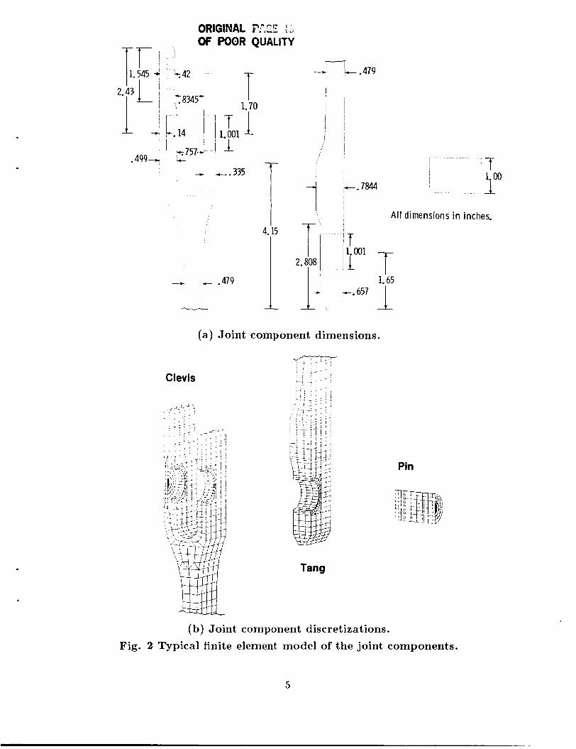
The joint cross sectional dimensions taken from engineering drawings are shown in figure
2a and used as input to GEOMOD. This mathematical description is used in SUPERTAB
3
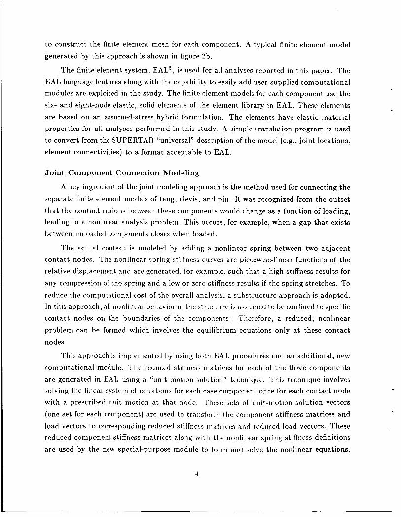
to construct the finite element mesh for each component. A typical finite element model
generated by this approach is shown in figure 2b.
The finite element system, EAL5, is used for all analyses reported in this paper. The EAL language features along with the capability to easily add user-supplied computational
modules are exploited in the study. The finite element models for each component use the
six- and eight-node elastic, solid elements of the element library in EAL. These elements are based on an assumed-stress hybrid formulation. The elements have elastic material properties for all analyses performed in this study. A simple translation program is used
to convert from the SUPERTAB “~niversal’~ description of the model (e.g., joint locations, element connectivities) to a format acceptable to EAL.
Joint C o m p o n e n t Connec t ion Mode l ing
A key ingredient of the joint modeling approach is the method used for connecting the
separate finite element models of tang, clevis, and pin. It was recognized from the outset
that the contact regions between these components would change as a function of loading, leading to a nonlinear analysis problem. This occurs, for example, when a gap that exists between unloaded components closes when loaded.
The actual contact is modeled by adding a nonlinear spring between two adjacent
contact nodes. The nonlinear spring stiffness curves are piecewise-linear functions of the relative displacement and are generated, for example, such that a high stiffness results for
any compression of the spring and a low or zero stiffness results if the spring stretches. To reduce the computational cost of the overall analysis, a substructure approach is adopted. In this approach, all nonlinear behavior in the structure is assumed to be confined to specific contact nodes on the boundaries of the components. Therefore, a reduced, nonlinear
problem can be formed which involves the equilibrium equations only at these contact
nodes.
This approach is implemented by using both EAL procedures and an additional, new
computational module. The reduced stiffness matrices for each of the three components are generated in EAT, using a “unit motion solution” technique. This technique involves solving the linear system of equations for each case component once for each contact node with a prescribed u n i t motion at that node. These sets of unit-motion solution vectors
(one set for each component) are used to transform the component stiffness matrices and
load vectors to corresponding reduced stiffness matrices and reduced load vectors. These reduced component stiffness matrices along with the nonlinear spring stiffness definitions
are used by the new special-purpose module to form and solve the nonlinear equations.
4
ORIGINAL P!.Z I, OF POOR QUALITY
4.15
1
l - 7 -r .479
f 1.00
2.808 1 1
I I A l l dimensions in inches.
T
T T 1.65
1 --. 657 1- (a) Joint component dimensions.
Tang
Pin
(b) Joint component discretizations. Fig. 2 Typical finite element model of the joint components.
5
The reduced nonlinear equations are solved using a full Newton-Raphson technique and convergence is rapid. The nonlinear solution vector of the overall problem is recovered by using the solution of the reduced equations and the sets of unit-motion solution vec-
tors. This substructuring approach is considerably more convenient and cost effective than
solving a set of non1inea.r equations for the overall system.
ORIGINAL JOINT
This section discusses the specific details of analyzing the original SRM tang-clevis
joint design. Deflections from analysis and tests are compared and analytical values of stress are presented.
Correlation with Referee Test Data
The “referee tests” a t Morton-Thioko12 were designed to gain a better understanding of the deflection behavior of the tang-clevis joint and to aid in the verification of analytical
models. The test article consisted of a lightweight case segment tang joined to a lightweight
case segment clevis that also included additional structure for connecting the external tank attachment rings. Both cases had been used previously on earlier shuttle flights. Domed end closures seal the ends of the two segment test article. This assembly was tested under
hydrostatic pressure from zero to 1004 psi. Displacement transducers were used to monitor
the relative radial and axial motion between tang and clevis. Strain gages were used to measure hoop st,raiii in the vicinity of the joint. Radial case growth can be calculated using the measured hoop strain and the nominal segment radius a t each gage location.
The displacement, transducers measure relative motion between tang and inner clevis a rm midway between the two O-ring grooves. Unless otherwise stated, the calculated average
gap motion presented in this paper is also for the location midway between the two O-ring grooves. The initial gap between the inner clevis arm and the tang increases with positive values of gap motion and decreases for negative values.
The finite element model used in the comparisons is basically that shown in figure 2.
The material properties used for the D6AC steel shell are E = 29.0 x loG psi and u = .3.
The material properties used for the MP35N steel pin are E = 34.0 x 10‘ psi and v = .45.
The contact between pin and tang, and between pin and clevis arms is modeled with the nonlinear springs described previously. For the baseline analysis case, no clearance around the pin is assumed. High contact forces develop around the pin under the pressure load.
Even with a low coefficient of friction. thew contact, forces are sufficient t o prevent the tang and clevis arms from sliding along the pin. Pin friction is imposed by constraining the
displacement components tangent to the surface of the pin and the surfaces of the pin hole
6
7' : I I+ G0011. 3111.324
L3 " I
l i G002I. 2371.227 G0031. 2301.217 G0041. 2241.213
I:{ I I G0051. 2081.199 lkhie GOMI. 2031.200
GO071 2011 200 G0081: 2021: 202 G0091. 2071.211 G0101. 2111.218 G O l l / . 217/. 237
' I
I
Ai.
/ I
1 G012I. 2241.312 I
I '
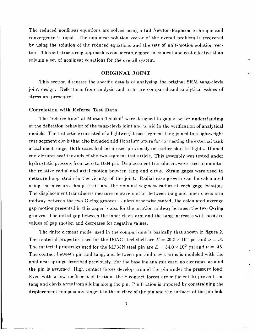
(a) R a d i a l deflections of case segment. (Gage No./Test, in . /Analysis , in.)
Fig. 3 Referee test a n d ana ly t ica l resu l t s compar i son .
in the clevis arms and tang to be identical. Stiff springs are used to impose these frictional
constraints in the contact regions. The applied loading is 1000 psi internal pressure which
is assumed to act on the surfams of the inner clevis arm and tang down to the top of the primary O-ring groove. The resulting axial component of this pressure load is also applied
and corresponds to a 36,500 lb/in. axial stress resultant in the shell wall (approximately
92,000 pounds of axial force at each pin).
A comparison of deflections from the referee test and analysis is shown in figure 3.
These deflections have been exaggerated in the deformed geometry plots. The agreement
between radial case deflections determined from strain gage measurements and analytical values is generally good as indicated in figure 3a. The location of gage 12 is near the rings
used for attaching the external tank attachment rings. Although these rings are part of the test specimen, the rings are not included in the present analytical model. The presence
7
- $ 1 i I I-;." Relative displacement between tang and outer clevis a r m
I ' ' 4 "
I 1 I
I
I
1
Re la t ive d i splace me n t between tang and i n n e r clevis a rm (average gap motion 1
Radial/. 037/. 0244
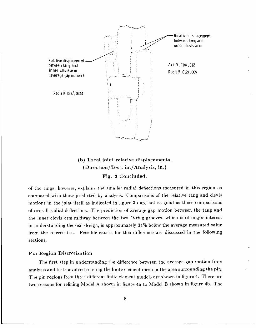
(b) Local joint relative displacements. (Direction/Test,, in./Analysis, in.)
Fig. 3 Concluded.
of the rings, however, explains the snialler radial deflections measured in this region as
compared with those predicted by analysis. Comparisons of the relative tang and clevis motions in the joint itself as indicated in figure 3b are not as good as those comparisons
of overall radial deflections. The prediction of average gap motion between the tang and the inner clevis arm midway between the two O-ring grooves, which is of major interest
in understanding the seal design, is approximately 34% below the average measured value from the referee t,est. Possible causes for this difference are discussed in the following
sections.
Pin Region Discretization
The first step in understanding the difference between the average gap motion from
analysis and tests involved refining the finite element mesh in the area surrounding the pin. The pin regions from three different finite elerrlent, models are shown in figure 4. There are two reasons for refining Model A shown in figure 4a to Model B shown in figure 4b. The
8
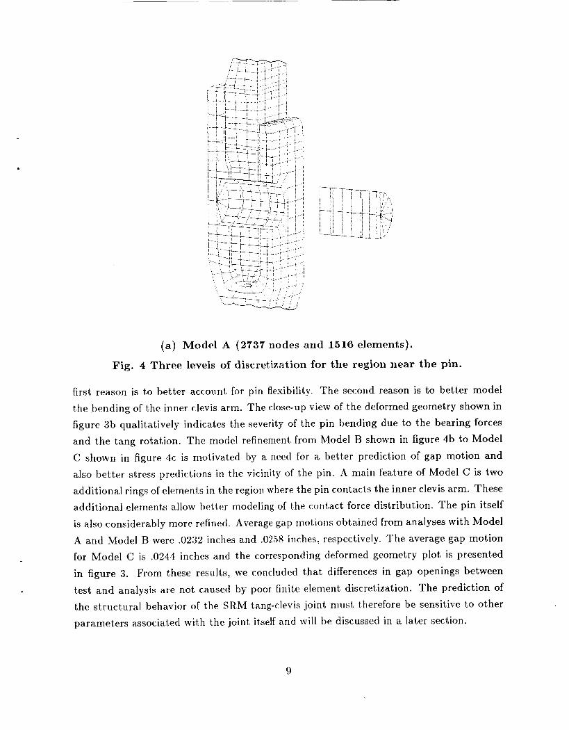
(a) Model A (2737 nodes and 1516 elements).
Fig. 4 Three levels of discretization for the region near the pin.
first reason is to better account for pin flexibility. The second reason is to better model the bending of the inner clevis arm. The close-up view of the deformed geometry shown in figure 3b qualitatively indicates the severity of the pin bending due to the bearing forces and the tang rotation. The model refinement from Model B shown in figure 4b to Model
C shown in figure 4c is motivated by a need for a better prediction of gap motion and also better stress predictions in the vicinity of the pin. A main feature of Model C is two
additional rings of elements in the region where the pin contacts the inner clevis arm. These additional elements allow better modeling of the contact force distribution. The pin itself
is also considerably more refined. Average gap motions obtained from analyses with Model
A and Model B were .0232 inches arid .0258 inches, respectively. The average gap motion for Model C is .0244 inches and the corresponding deformed geometry plot is presented
in figure 3. From these results, we concluded that differences in gap openings between
test and analysis are not caused by poor finite element discretization. The prediction of the structural behavior of the SRM tang-clevis joint must therefore be sensitive to other parameters associated with the joint itself and will be discussed in a later section.
9
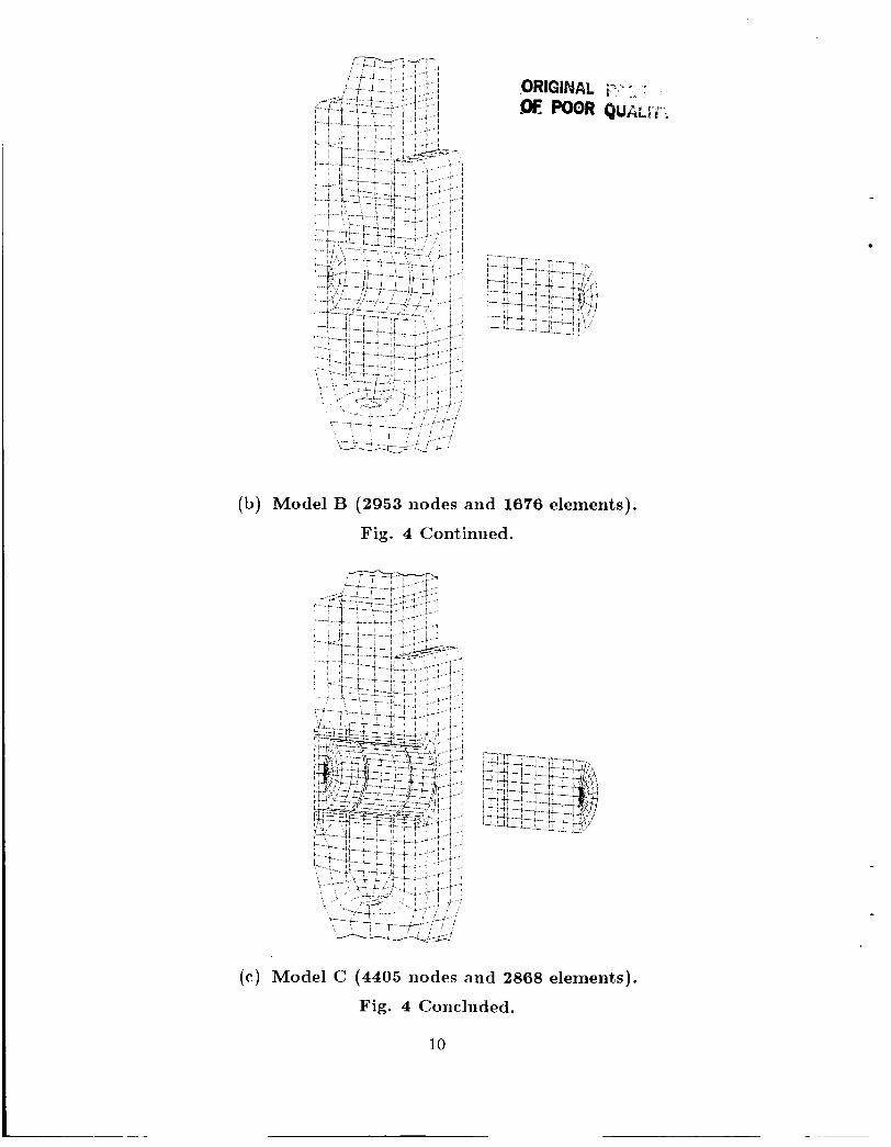
(b) Model B (2953 nodes and 1676 elements).
Fig. 4 Continued.
(c ) Model C (4405 nodes and 2868 elements).
Fig. 4 Concluded.
10
I i l ~
17017
361 130
J--’ 178/ -201
Stress (ksi) = u / u hoop axial
-2391 -158 -2151 -173 -414/ -403
-1991 -339 ?.-[{ - 1 0 5 / - 2 5 0 ~ i
-2481 -234 j y 1 6 4 , -158
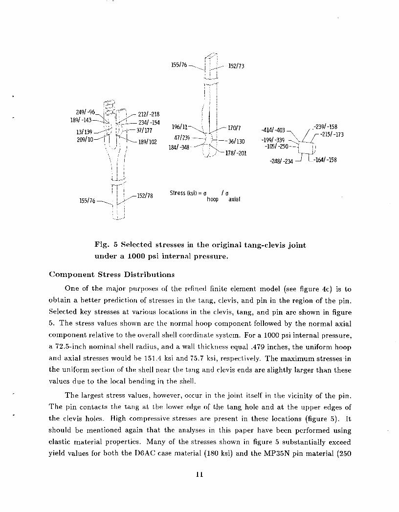
Fig. 5 Selected stresses in the original tang-clevis joint under a 1000 psi internal pressure.
Component Stress Distributions
One of the major purposes of the refined finite element model (see figure 4c) is to
obtain a better prediction of stresses in the tang, clevis, and pin in the region of the pin.
Selected key stresses at various locations in the clevis, tang, and pin are shown in figure 5. The stress values shown are the normal hoop component followed by the normal axial
component relative to the overall shell coordinate system. For a 1000 psi internal pressure,
a 72.5-inch nominal shell radius, and a wall thickness equal .479 inches, the uniform hoop and axial stresses would be 151.4 ksi and 75.7 ksi, respectively. The maximum stresses in the uniform section of the shell near the tang and clevis ends are slightly larger than these
values due to the local bending in the shell.
The largest stress values, however, occiir in the joint itself in the vicinity of the pin. The pin contacts the tang a t the lower edge of the tang hole and a t the upper edges of
the clevis holes. High compressive stresses are present in these locations (figure 5). It should be mentioned again that the analyses in this paper have been performed using elastic material properties. Many of the stresses shown in figure 5 substantially exceed yield values for both the DGAC case material (180 ksi) and the MP35N pin material (250
11

ksi). The main purpose of presenting these stresses is to demonstrate the need for analyses which include plasticity effects and to indicate the areas where plastic deformations are likely to occur.
The outward bending of the tang has a significant effect on the stress distribution.
The compressive, contact stress a t the inside tang hole circle is over -300 ksi while at the outside tang hole circle the stress is about -200 ksi. A tensile stress concentration
also occurs around the tang hole, approximately 90” from the maximum contact location. Again, these high tensile stresses vary significantly from inside hole circle to outside hole circle due to tang bending.
At the edges of the pin holes in the tang and clevis, opposite the maximum contact locations, there are stress concentrations due to the hoop loads. These tensile hoop stresses are 209 ksi and 189 ksi at the lower edges of the clevis arm holes and 196 ksi and 170 ksi at the upper edge of the tang hole.
There are particularly high compressive stresses a t the inner end of the pin in both
the hoop and axial directions. Because the yield stress of the pin material is substantially higher than that of the case material, the relief of these stresses in the actual hardware is
probably due mainly t o the yielding of the inner clevis arm.
TANG-CLEVIS JOINT SENSITIVITIES
As discussed in the previous section, the finite element model of the tang-clevis joint does not predict gap motions as large as those measured in the referee tests. However,
we believe that the finite element analysis accurately predicts the deflections of the “ideal design” joint. Thus, the difference between the baseline finite element model and test must
be due to small details in the joint design which have a significant effect on its behavior.
This section discusses studies which attempt to identify these sensitivities. Understanding the sensitivity of the joint to various parameters is important, not only to achieve better correlation between test and analysis, but also to obtain a thorough understanding of the
joint behavior.
Pin-Tang Clearance
Clearances between the three joint components (tang, clevis, pins) obviously must exist to satisfy assembly requirements. An analysis has been performed with a prescribed uniform clearance around the pin circumference at the tang, and inner and outer clevis arm holes. Under the internal pressure load, the joint extended uniformly in the axial direction
until the clearance was closed. The joint behavior is essentially the same as without the
12
Average gap
mot ion,
in.
I nner clevis
4 .02 clevis
a r m -
-
I 1 I I 1 I 0.0 .002 .OM .006 .008 .010
Fig. 6 Effect of t ape red c l ea rance at the p in - t ang in te r face on gap motion.
clearance except that the relative axial motion between tang and clevis increased by an
amount equal to the clearance. Similar behavior results if the clearance is prescribed only
a t the tang hole or only a t the two clevis arm holes. Thus, this type of clearance does not explain the discrepancy in gap motions.
A second clearance study is motivated by a careful scrutiny of the analytical stress distributions in the vicinity of the pin. From figure 5, it can be seen that the stresses in the tang are larger a t the inside of the hole (nearest the shell centerline) than a t the outside.
Tang bending causes both the compressive, contact stresses and the tensile stresses 90"
from the maximum pin contact location to be larger a t the inside hole circle than a t the
outside hole circle, Furthermore, these stresses considerably exceed the yield values for the D6AC material. I t is possible that a differential clearance caused by material yielding develops at, the tang holes. This differential clearance is larger a t the tang hole inside circle
than at the outside circle (i.e., a tapered pin hole or1 the tang).
Results from a study with this type of clearance modeled are presented in figure 6. In this study, a linear clearance or taper along the tang hole is assumed starting from zero a t
the outside hole circle to a value of A T at the inside hole circle. Figure 6 shows average
gap motion plotted as a function of AT. There is considerable change in gap motion as
13
AT is increased and for largc. A T , the averagca gap rriotion approaches the measured values
from tests.
Pin-Inner Clevis Arm Clearanccb
Other studies of tang-clevis joint behavior have reported the sensitivity of the gap motion to the contact forw distribution t)etwccli pin and inner clevis arm. As the center-
of-load between pin and inner clevis arm is rnoved outboard toward the tang (i.e., axial load eccentricity), the gap motion becomes larger.
.04
Average 1
02 gap
motion,
in.
0.0
-1 I n n e r t clevis Ac arm-’
-
. 001 .002 .003 .OM .OB
A,, In.
Outer clevis a r m
Fig. 7 Effect, of clearance at, the pin-inner clevis arm interface on gap motion.
One of the specific purposes in refining the finite element mesh in the vicinity of the
pin (as discussed previously) is to determine if this center-of-load location is sensitive to mesh refinement. Models A and B (see figures 4a and 4b) have only two nodes for contact
between pin and inner clevis arm along the pin centerline. The most refined model Model C (figure 4c) has four nodes to represent the contact force distribution in this region. However, the gap motion predictions from these models are very close, indicating that the
models represent, the pin-inner clevis arm contact distribution reasonably well for the ideal
joint.
1 4
However, this analytically-predicted contact force distribution may be incorrect for the actual joint hardware. As mentioned previously, very high axial stresses are predicted
in the pin along its inside edge. The yielding that probably occurs in the inner clevis arm to relieve these pin stresses causes the center-of-load between pin and clevis to move
outboard. A second possible effect on the contact distribution is how the pin end mates with the inside of the inner clevis arm hole. The ideal finite element model assumes perfect contact a t the inside of the hole. However, the chamfer at the pin end may make this difficult to achieve resulting in less axial load being transmitted a t the pin end than
predicted by analysis.
The contact force distribution change caused by either of these effects can be studied
by specifying a small clearance between the pin and the inner clevis arm in the finite
element model. This clearance is specified only a t the inner most circle of nodes on the pin, and reduces the load transmitted between the pin and clevis arm a t this specific
location. The average gap motion as a function of this clearance is shown in figure 7. For the larger values of clearance, average gap motions in the range of measured values for the referee test (i.e., over .030 inches) are predicted.
Shim Thickness
Metal shims are inserted between the tang and outer clevis arm at each pin during assembly to help control the clearance between tang and inner clevis arm a t the O-ring
sealing surface. Specified manufacturing tolerances on the tang allow the thickness a t the
sealing surface to vary between .777 and .792 inches. The inner spacing between clevis arms varies between .827 and .842 inches. Thus, the total clearance at the O-ring location can vary between .035 and .065 inches.
A study has been performed to determine the effect of shim thickness on gap motion.
Average gap motion is shown as a function of shim thickness for two cases in figure 8. The first case specifies no clearance between the pin and tang a t the pin hole. The second case
specifies a pin hole taper equal to .007 inches. With no pin-tang clearance, the average gap
motion decreases only slightly with increasing shim thickness. This trend is inconsistent
with the results of reference 2 which report a measured reduction in gap opening of .008 inches when the shim thickness is changed from .034 to .050 inches. With .007 inches
of pin hole taper, there is a .004-inch reduct#ion in average gap motion when the shim
thickness is changed from .034 to .050 inches. These results reflect the trends reported for the referee test and add credibility to the theory that tapering of the pin hole contributes
substantially to gap motion.
15
c ’
.a0
.030
Average .020 gap
motion, in.
.OH
0
A L
A T - f 1
T t o Untapered pin hole
a Tapered pin hole
I 1
.030 ,040 . 6 0 . 060 .070
Shim thickness, in.
Fig. 8 Effect of shim thickness on gap motion.
Pin Friction
Friction between the pins and tang and between the pins and clevis arms influences the structural behavior of the tang-clevis joint. Clearances between the tang and clevis arms allow the tang t o slide on the pins after assembly. This sliding is resisted only by frictional forces bet,ween tang and pins or contact between the tang and the inner or outer
clevis arm.
The internal motor pressure increases from zero to near 1000 psi within 600 millisec- onds after SRM ignition. During this pressure transient, the load on the pins changes from compression due to the weight of the shuttle to tension due to the pressurization of the motor. At some point in this transient, forces on the pins are theoretically zero and sliding of the tang on the pins is possible. After this initial sliding, the axial load at each pin is approximately 92,000 Ibs at SRM full pressurization which is probably sufficient to lock the tang on the pins during flight. The analysis results presented in this paper assume this
locked condition.
To determine the effect of this assumption, an analysis has been performed where the friction between tang and pin is neglected. This analysis assumes a total clearance between
tang and clevis arms of .065 inches. This clearance is partially taken up by a .034-inch shim
16
rl
@ Interference
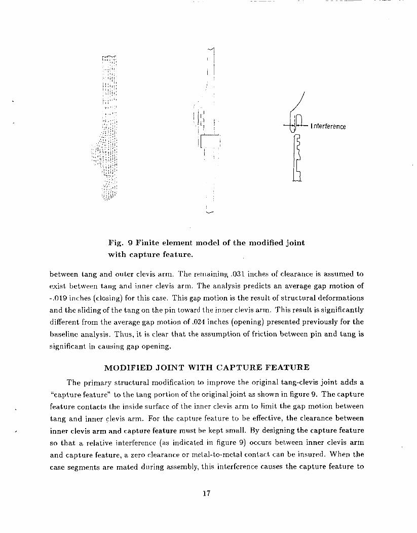
Fig. 9 Finite element model of the modified joint with capture feature.
between tang and outer clevis arm. The remaining .031 inches of clearance is assumed to exist between tang and inner clevis arm. The analysis predicts an average gap motion of -.019 inches (closing) for this case. This gap motion is the result of structural deform.ations
and the sliding of the tang on the pin toward the inner clevis arm. This result is significantly different from the average gap motion of .024 inches (opening) presented previously for the
baseline analysis. Thus, it is clear that the assumption of friction between pin and tang is
significant in causing gap opening.
MODIFIED JOINT WITH CAPTURE FEATURE
The primary structural modification to improve the original tang-clevis joint adds a “capture feature” to the tang portion of the original joint as shown in figure 9. The capture feature contacts the inside surface of the inner clevis arm to limit the gap motion between
tang and inner clevis arm. For the capture feature to be effective, the clearance between
inner clevis arm and capture feature must be kept small. By designing the capture feature so that a relative interference (as indicated in figure 9) occurs between inner clevis a rm
and capture feature, a zero clearance or metal-to-metal contact can be insured. When the
case segments are mated during assembly, this interference causes the capture feature to
17
bend inward slightly and the inner clevis arm to bend outward (toward the tang) slightly. The bending of the inner clevis arm towards the tang reduces the initial gap a t the O-ring sealing surface.
As long as the magnitude of the interference is sufficient to insure zero clearance between inner clevis arm and capture feature, the gap opening under the pressure loading is essentially independent of the amount of interference. However, stresses will be introduced
in both tang and clevis components during assembly which add to the stresses resulting
from the external loads.
In the capture feature joint concept, it is possible to introduce a third O-ring in the capture feature which seals against the inside surface of the inner clevis arm. An advantage of this O-ring location is that , under increasing internal pressure, the O-ring becomes more compressed. There are two main structural implications of including this third O-ring. First, the O-ring groove removes a portion of the capture feature thus making it slightly
more flexible. Second, the pressure loading on the capture feature and inner clevis arm
can be different from the case without, the third O-ring. With the third O-ring sealing, the pressure is prevented from reaching the primary O-ring. In the studies reported herein,
without the third O-ring, the internal pressure acts on the capture feature and inner clevis
arm up to the primary O-ring.
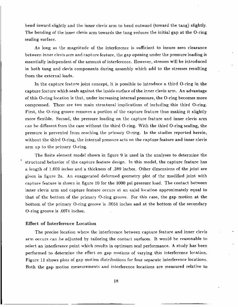
The finite element model shown in figure 9 is used in the analyses to determine the structural behavior of the capture feature design. In this model, the capture feature has a length of 1.603 inches and a thickness of .389 inches. Other dimensions of the joint are
given in figure 2a. An exaggerated deformed geometry plot of the modified joint with capture feature is shown in figure 10 for the 1000 psi pressure load. The contact between
inner clevis arm and capture feature occurs at an axial location approximately equal to that of the bottom of the primary O-ring groove. For this case, the gap motion at the
bottom of the primary O-ring groove is .0051 inches and at the bottom of the secondary O-ring groove is .0074 inches.
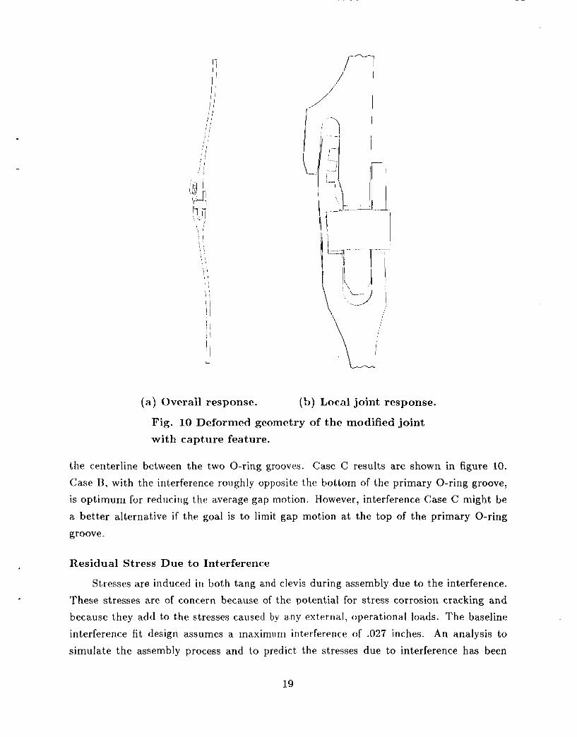
Effect of Interference Loca t ion I The precise location where the interference between capture feature and inner clevis
arm occurs can.be adjusted by tailoring the contact surfaces. It would be reasonable to
select an interference point which results in optimum seal performance. A study has been performed to determine the effect on gap motions of varying this interference location. Figure 11 shows plots of gap motion distributions for four separate interference locations.
Both the gap motion measurements and interference locations are measured relative to
18
L
(a) Overall response. (b) Local joint response.
Fig. 10 Deformed geometry of the modified joint with capture feature.
the centerline between the two O-ring grooves. Case C results are shown in figure 10. Case B, with the interference roughly opposite the bottom of the primary O-ring groove, is optimum for reducing the average gap motion. However, interference Case C might be
a better alternative if the goal is to limit gap motion a t the top of the primary O-ring
groove.
Residual Stress Due to Interference
Stresses are induced in both tang and clevis during assembly due to the interference. These stresses are of concern because of the potential for stress corrosion cracking and because they add to the stresses caused by any external, operational loads. The baseline
interference fit design assumes a maximum interference of .027 inches. An analysis to
simulate the assembly process and to predict the stresses due to interference has been
19
Capture feature-, T X
-012
Gap mot ion,
in.
.008
.004
0 -1.0 0 1.0
Distance from centerline between O-ring grooves X, in.
Fig. 11 Effect of capture feature-inner clevis arm contact location on gap motion.
performed. In this analysis, there are no external loads present, the tang is free to slide along the pin, and the maximum baseline interference is used. After “assembly”, the
average gap has closed approximately .026 inches indicating that most of the deformation
occurs in the inner clevis arm rather than the capture feature. This result also indicates that improvements in the design from stiffening the capture feature will be small. The
interference force between capture feature and inner clevis arm is 210 Ibs/degree. The
stresses induced due to the interference fit are small. The maximum stress is 12 ksi and it occurs at the top edge of the pin hole in the inner clevis arm.
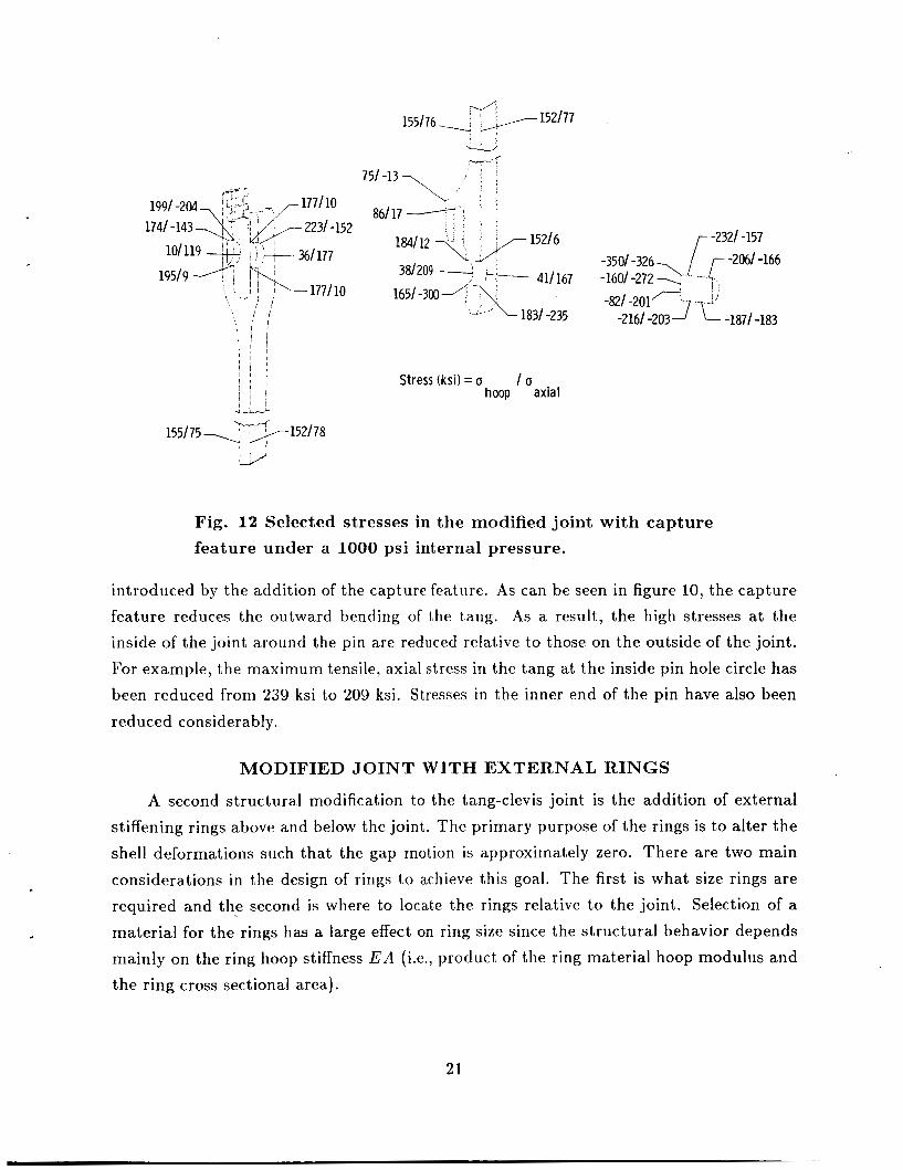
Component Stress Distributions
The stresses in the baseline capture feature design under the 1000 psi internal pressure load are of more concern. The analysis performed does not include the effect of the interference, but as mentioned above, these stresses are small. Selected key stress values
are shown in figure 12. The stress values are similar to those in the original joint as shown
in figure 5 . However, there are some small, but significant changes to specific stresses
20
155/76\ 9 ,,y- 152177
1991 -204 1741 -143
-177110
\ 86/17 -C
15216
411167 -x/-
381209 - ,-- 165/ -300 -"T\
-- 1831-235
-2321 -157 -3501 -326 [-- -2061-166 - 1 6 0 / - 2 7 2 2 j ,
-821 -201 -2161 -203 1 f! -1871 -183
Stress (ksi) = o I o hoop axial
l 5 5 I 7 5 7 ?7-f pq- 152178
Fig. 12 Selected stresses in the modif ied jo in t w i t h c a p t u r e
f e a t u r e under a 1000 psi in te rna l pressure .
introduced by the addition of the capture feature. As can be seen in figure 10, the capture feature reduces the outward bending of t,he tang. As a result, the high stresses at the
inside of the joint around the pin are reduced relative to those on the outside of the joint. For example, the maximum tensile, a.xial stress in the tang at the inside pin hole circle has
been reduced from 239 ksi to 209 ksi. Stresses in the inner end of the pin have also been
reduced considerably.
MODIFIED JOINT WITH EXTERNAL RINGS
A second structural modification to the tang-clevis joint is the addition of external
stiffening rings above and below the joint. The primary purpose of the rings is to alter the shell deformations such that the gap motion is approximately zero. There are two main
considerations in the design of rings to achieve this goal. The first is what size rings are required and the second is where to locate the rings relative to the joint. Selection of a
material for the rings has a large effect on ring size since the structural behavior depends mainly on the ring hoop stiffness E A (i.e., product, of the ring material hoop modulus and
the ring cross sectional area).
21
Graphite-epoxy composite is an attractive material system for the rings because of its high extensional stiffness and low density. In addition, the motor can be manufactured
by filament winding the graphite fibers around the steel cases. A big drawback to the
graphite material is the difference between the coefficient of thermal expansion of the graphite rings and the steel case. Graphite-epoxy composite has a coefficient of thermal expansion approximately equal zero while the coefficient of thermal expansion for steel is 6.6 x lopG in./in./"F.
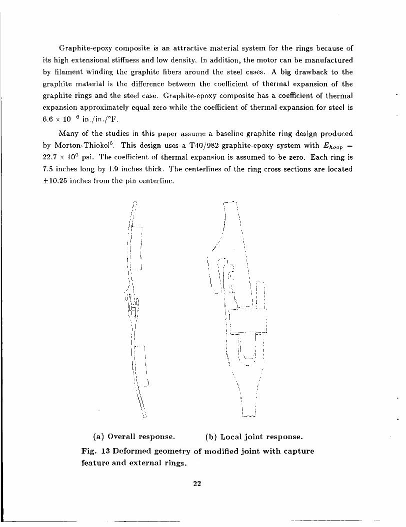
Many of the studies in this paper assume a baseline graphite ring design produced by Morton-ThiokolG. This design uses a T40/982 graphite-epoxy system with Ehoop =
22.7 x loG psi. The coefficient of thermal expansion is assumed to be zero. Each ring is 7.5 inches long by 1.9 inches thick. The centerlines of the ring cross sections are located f10.25 inches from the pin centerline.
(a) Overall response. (b) Local joint response.
Fig. 13 Deformed geometry of modified joint with capture feature and external rings.
22
The rings can (~Ift~ctivcly control gap motiorl when added to SRM case segments with
either the original joints or the rriodilied joints with the capture featiire. Both approaches are consideixd i r i t tic studics rcported herein. Ari cxaggerated deformed geornetry plot of
the capture feat urv design including tlic baseliiic~ ring configuration is shown in figure 13.
The overall shell tleforinations shown i n figurci I:Ja arc considerably different from those shown in figure I O a . The graphite rings have highcr hoop stiffness than the joint which
reverses the bending direction between t,hc rings and the joint. As a result, the average gap between the tang and inner clevis arm closcs .013 inches under the 1000 psi internal
pressure load. Lkcaiise thv deformations are exagcratcd in figure 13b, this closing of .013
inches appears to cause the inner cltivis arm to overrun the tang. However, the initial
clearance betweeii the inl1t.r clevis a rm arid tlic tang is such that contact does not occur.
Effect of Ring Stiffness
The “ideal” ring design would result in exactly zero gap motion under the applied
loading. This ideal dcsign is optimum from two points of view. First, the weight penalty
associated with the rings is kept to a minimum. Second, this design results in the most stable sealing condition for the O-rings. Adding stiffness to the rings (as in the baseline
design) will produce a design where the gap closes as the internal pressure increases after SRM ignition. However, as the internal motor pressure decreases from its maximum value, the gap opens resulting in a potential loss of sealing capability. The gap in a design
with undersized rings will tend to open during internal pressure buildup and close as the pressure decreases. Again, there is a potential for loss of sealing capability.
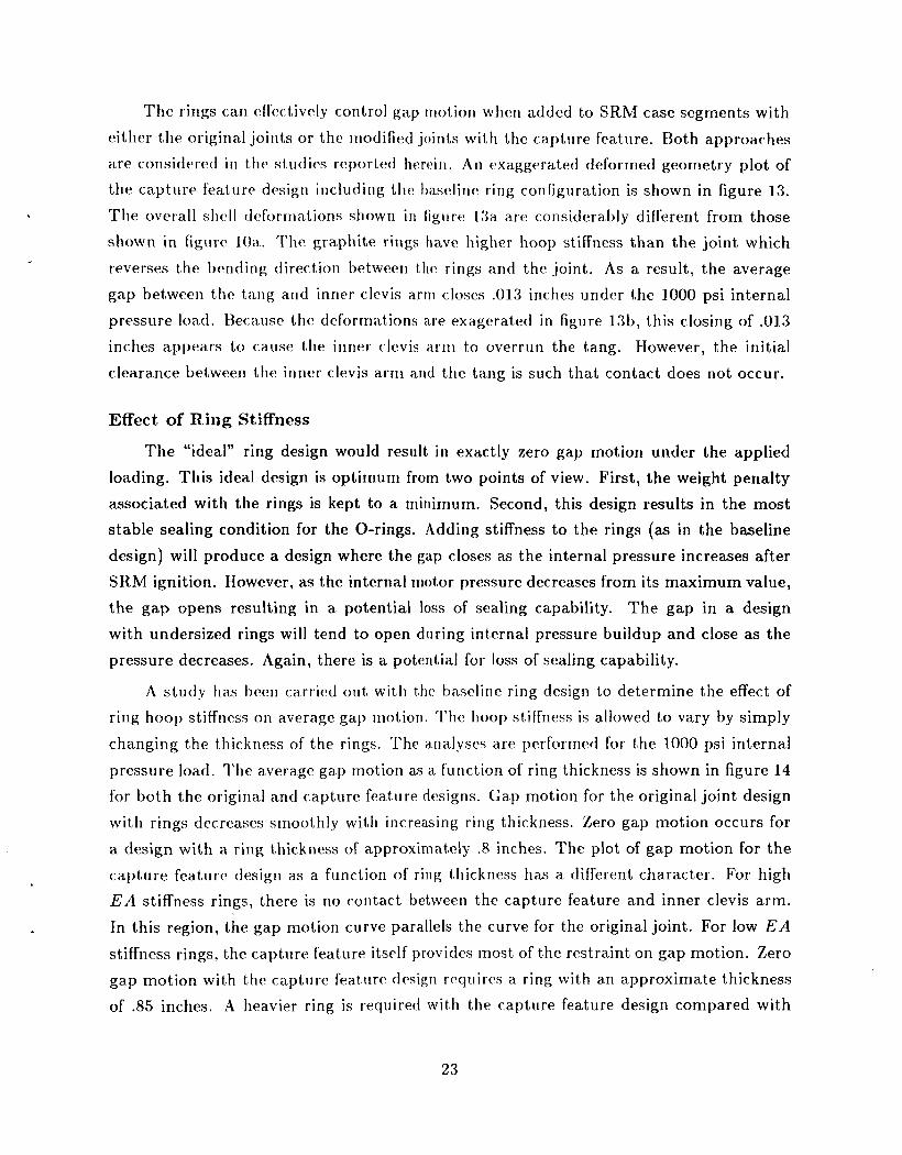
A study tias 13ecw carried out with the t);lsclinc ring design to determine the effect of ring hoop stiffness on average gap niotion. The hoop stiffness is allowed to vary by simply
changing the thickness of the rings. The analyses are performed for the 1000 psi internal
pressure load. The average gap motion as a function of ring thickness is shown in figure 14 for both the original and capture feature dcsigns. Gap motion for the original joint design
with rings decreases smoothly with increasing ring thickness. Zero gap motion occurs for
a design with a ring thickness of approximately .8 inches. The plot of gap motion for the capture feature desigri as a function o f ring thickness has a different character. For high
E A stiffness rings, there is no contact between the capture feature and inner clevis arm.
In this region, the gap motion curve parallels the curve for the original joint. For low E A stiffness rings, the capture feature itself provides most of the restraint on gap motion. Zero gap motion with the capture feature desigri requires a ring with a n approximate thickness of .85 inches. A heavier ring is required wit ti the capture feature design compared with
23
T l l
Average gap
motion, in.
-. * O r 01
\
n-.
,--Or igi na I joint
Modified joint with capture feature
in.
6 E = 22.7 x 10 psi
-. 02 I I 1
0 1.0 2.0 Ring thickness t, in.
Fig. 14 Effect of external ring stiffness on gap motion
the original design because the capture feature itself adds more hoop stiffness at the joint
which must be counteracted by the ring hoop stiffness.
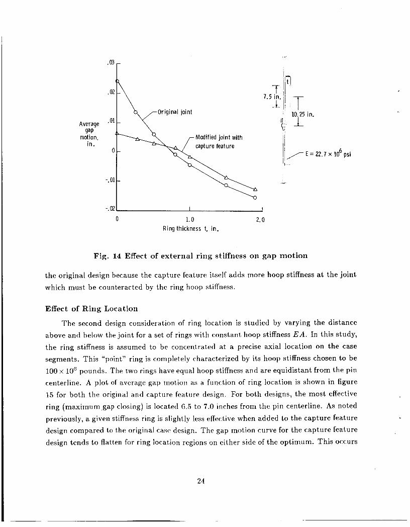
Effect of Ring Location
The second design consideration of ring location is studied by varying the distance above and below the joint for a set of rings with constant hoop stiffness E A . In this study,
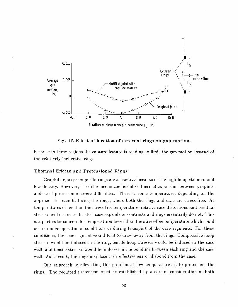
the ring stiffness is assumed to be concentrated at a precise axial location on the case segments. This “point” ring is completely characterized by its hoop stiffness chosen to be 100 x 10‘ pounds. The two rings have equal hoop stiffness and are equidistant from the pin centerline. A plot of average gap rnotion as a function of ring location is shown in figure 15 for both the original and capture feature design. For both designs, the most effective
ring (maximum-gap closing) is located 6.5 to 7.0 inches from the pin centerline. As noted
previously, a given stiffness ring is slightly less effective when added to the capture feature design compared to the original case design. The gap motion curve for the capture feature
design tends to flatten for ring location regions on either side of the optimum. This occurs
24
I
Ft
0 -
-0.005
Average gap
motion, in.
-0.005
0,010
0.005
Original joint
I 1
External-("$ rings
I ,rMcdified joint with A
-Pin center Ii ne
4.0 5.0 6.0 7.0 8.0 9.0 10.0
Location of rings from pin centerline LR, in.
Fig. 15 Effect of location of external rings on gap motion.
because in these regions the capture feature is tending to limit the gap motion instead of the relatively ineffective ring.
Thermal Effects and Pretensioned Rings
Graphite-epoxy composite rings are attractive because of the high hoop stiffness and low density. However, the difference in coefficient of thermal expansion between graphite and steel poses some severe difficulties. There is some temperature, depending on the
approach to manufacturing the rings, where both the rings and case are stress-free. At
temperatures other than the stress-free temperature, relative case distortions and residual stresses will occur as the steel case expands or contracts and rings essentially do not. This
is a particular concern for temperatures lower than the stress-free temperature which could occur under operational conditions or during transport of the case segments. For these
conditions, the case segment would tend to draw away from the rings. Compressive hoop
stresses would be induced in the ring, tensile hoop stresses would be induced in the case wall , and tensile stresses would be induced in the bondline between each ring and the case
wall. As a result, the rings may lose their effectiveness or disbond from the case.
One approach to alleviating this problem at low temperatures is to pretension the
rings. The required pretension must be established by a careful consideration of both
25
-Z
. .
I 8.5 x 10
w = radial deflection oo= ring pretension stress
9 -
oO Ib 0
- 8.5 x I I 1 I I I I I -15 -10 -5 0 5 10 15
Distance from pin centerline Z, in.
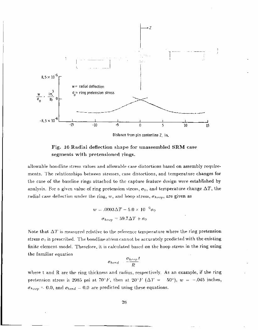
Fig. 16 Radial deflection shape for unassembled SRM case segments with pretensioned rings.
allowable bondline stress values and allowable case distortions based on assembly require-
ments. The relationships between stresses, case dist,ortions, and temperature changes for
the case of the baseline rings attached to the capture feature design were established by analysis. For a given value of ring pretension stress, un, and temperature change AT, the
radial case deflection under the ring, w , and hoop stress, ohoop , are given as
Note that A T is measured relative to the reference temperature where the ring pretension
stress c~ is prescribed. The bondline stress cannot be accurately predicted with the existing finite element model. Therefore, it is calculated based on the hoop stress in the ring using the familiar equation
where t and R are the ring thickness and radius, respectively. As an example, if the ring pretension stress is 2985 psi a t 7 0 " F , t'hen at 20°F' ( A T = -50"), w = -.045 inches,
uhc,ol, = 0.0, and ubond = 0.0 are predicted using these equations.
26
For case assembly considerations, the deflection pattern at the case ends caused by the ring pretension is also important. An analysis was performed with pretensioned, baseline-
design, rings on detached tang and clevis case segment ends. In figure 16, the radial deflection normalized by ring pretension stress is shown as a function of distance from the
pin centerline. For reasonable values of pretension, such as the 2985 psi value considered
earlier, the unassembled case distortions are not large.
Component Stress Distributions
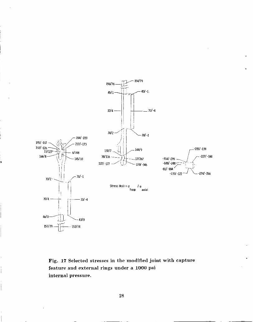
Selected key stress values are shown in figure 17 for the baseline external ring design under a 1000 psi internal pressure load. As mentioned previously, the rings in the baseline
ring design reverse the bending moment in the original design. The result is significant
inward bending of the tang and a .013-inch closing of the gap. This tang bending has a significant effect on the stresses in the vicinity of the pin. In contrast to the original joint design, the high values of contact and tensile stresses are at the outboard side of the joint. Stresses at the inside edge of the pin have been reduced slightly compared with the
original and capture feature designs. The stresses in the top and bottom rings are roughly the same. The largest value of hoop stress in the rings, approximately 45 ksi, occurs at the ring-shell interface on the ring edge away from the joint. This value is well within allowable values for a graphite-epoxy material system.
CONCLUDING REMARKS
Finite element structural analyses have been performed to predict both deflections and stresses in the SRM tang-clevis joint under the primary pressure loading condition. Correlations between test and analytical values of joint deflections have been made for
the original joint. The prediction of relative gap motion a t the O-ring sealing surface has
been emphasized because this motion is critical to the sealing capability of the joint. Two
modified tang-clevis joint designs have been evaluated.
The extensive analytical effort reported in this study indicates the difficulty in ac- curately predicting the structural behavior of this tang-clevis joint. One contributor to this difficulty is the problem of modeling the contact and clearances between the three
mating parts of the joint. Nonlinear analysis is required. A second contributor to the
analysis difficulty is the high stress level in the vicinity of the pin for all joint compo- nents. Compressive and tensile stresses are present which considerably exceed material yield allowables. Analyses including inelastic material properties are certainly required to
accurately predict, these stresses.
4
27
I I
c
2041 -220
1951 -107 -,$+ 2171 -173
1521 16618 -126 \ g 1 9 8 ‘’q- 145110
154179 156176
431 -1
281 -1 3012
13217 1441 9
Stress (ksi) = (I 1 (I hoop axial
-205/ -139 [/ -2271 -184 -1 /-T
-3141 -295 -148/-248’---r , ,
-811 -184 -2741 -266 -1331 -122
Fig. 17 Selected stresses in the modified joint with capture feature and external rings under a 1000 psi internal pressure.
28
Several studies were performed to determine the sensitivity of the joint structural behavior to parameter changes. Two of these studies imposed clearance distributions between pin a.nd tang, and pin and inner clevis arm that could be caused by material
yielding in these regions. The results show these clearances to have a significant effect on relative gap motion. This implies that analyses including inelastic material properties may also be important in obtaining accurate predictions of joint deflections. A third study
varied the thickness of the metal shims between tang and outer clevis arm. Results from
this study show that increasing the shim thickness can slightly reduce gap motion at the
O-ring sealing surface.
Frictional forces between pin and tang have been shown to significantly affect gap motion. When frictional forces are removed from the analysis, the gap closes rather than
opens.
Both the capture feature and external ring modifications to the original tang-clevis
design are effective in controling relative motion in the joint. The interference fit in the capture feature design is critical to limiting the gap opening to between .005 and .007
inches. Residual stresses due to the interference fit are low. External rings can be designed
which theoretically restrict gap motion to zero during pressurization. The effectiveness of
a given set of external rings depends on the ring hoop stiffness and location relative to the joint. Studies have shown that the optimum ring locations are about seven inches on
either side of the joint. Ring hoop stiffness is a direct function of the material used. The graphite-epoxy material considered in this study can be used in a practical design only if problems associated with the coefficient of thermal expansion mismatch between the steel case and the graphite-epoxy rings can be resolved.
29
REFERENCES
1. Report of the Presidential Commission on the Space Shuttle Challenger Accidend, Washington, D.C., June 6, 1986.
2. Oostyen, .J. E., Bright, D. D., Hawkins, G. F., McCluskey, P. M., and Larsen, G. L., SRM Joint Deflection Referee Test: Phase 2 Ftnal Report, Morton Thiokol, Inc., Wasatch Operations, Document, Number TWH-300149, April 3,1986.
3. SDRC I-DEAS GEOMOD - Solid Modeling and Design Reference Manual, Structural Dynamics Research Corporation, 1986.
4. SDRC I-DEAS SUPERTAB - Engineering Analysis Pre- and Post-Processing Refer- ence Manual, Structural Dynamics Research Corporation, 1986.
5. Whetstone, W . D., EISI-EA L Engineering Analysis Language Reference Manual - EISI-EAL System Level 312, Engineering Information Systems, Inc., August 1985.
6. SRM Case Field Jotnt and Case Nozzle I’resentatzon, Morton Thiokol, Inc., Wasatch Operations, Document Number TWR-15623, Publication Number 86634, Presented a t the Technical Interchange Meeting held at the NASA Marshall Space Flight Center,
Huntsville, AL, June 9-11, 1986.
c
30
1. Report No. NASA Thf-89018
4. Title and Subtitle Structural Behavior of the Space Shuttle SRM Tang-Clevis Joint
2. Government Accession No.
7. Author(s)
William H. Greene, Norman F. Knight, Jr. and Alan E. Stockwell
NASA Langley Research Center Hampton, VA 236655225
9. Performing Organization Name and Address
115. Supplementary Notes William H. Greene and Norman F. Knight Jr., Langley Research Center, Hampton, Virginia. Alan E. Stockwell, PRC Kentron, Inc., Hampton, Virginia.
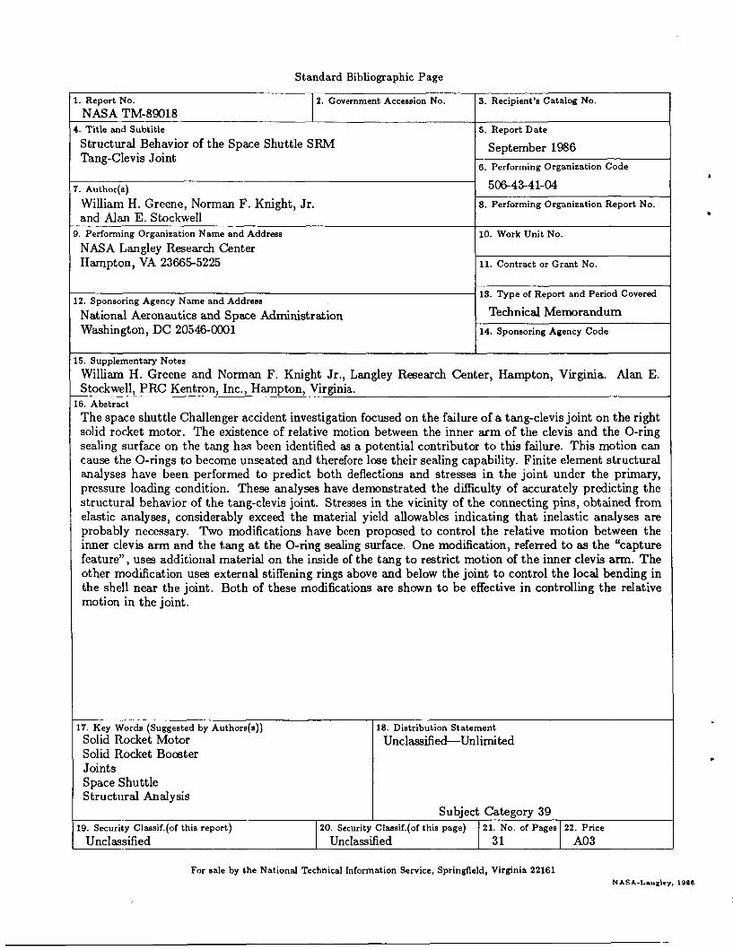
The space shuttle Challenger accident investigation focused on the failure of a tang-clevis joint on the right solid rocket motor. The existence of relative motion between the inner arm of the clevis and the O-ring sealing surface on the tang has been identified as a potential contributor to this failure. This motion can cause the O-rings to become unseated and therefore lose their sealing capability. Finite element structural analyses have been performed to predict both deflections and stresses in the joint under the primary, pressure loading condition. These analyses have demonstrated the difficulty of accurately predicting the structural behavior of the tang-clevis joint. Stresses in the vicinity of the connecting pins, obtained from elastic analyses, considerably exceed the material yield allowables indicating that inelastic analyses are probably necessary. Two modifications have been proposed to control the relative motion between the inner clevis arm and the tang at the O-ring sealing surface. One modification, referred to as the ‘capture feature”, uses additional material on the inside of the tang to restrict motion of the inner clevis arm. The other modification uses external stiffening rings above and below the joint to control the local bending in the shell near the joint. Both of these modifications are shown to be effective in controlling the relative
16. Abstract
12. Sponsoring Agency Name and Address National Aeronautics and Space Administration Washington, DC 20546-0001
17. Key Words (Suggested by Authors(s)) Solid Rocket Motor Solid Rocket Booster Joints Space Shuttle Structural Analysis
3. Recipient’s Catalog No.
18. Distribution Statement Unclassified-Unlimited
Subject Category 39
5. Report Date
September 1986 6. Performing Organization Code
5&4b41-04
19. Security Classif.(of this report) Unclassified
8. Performing Organization Report No.
20. Security Classif.(of this page) 21. No. of Pages 22. Price Unclassified 31 A03
10. Work Unit No.
11. Contract or Grant No.
13. Type of Report and Period Covered
Technical Memorandum 14. Sponsoring Agency Code
For sale by the National Technical Information Service, Springfield, Virginia 22161 NASA-Lsnglcy, 1966