stress analysis of bwb composite bulkhead beam using ansys. · pdf filestress analysis of bwb...
TRANSCRIPT
The International Journal Of Engineering And Science (IJES)
|| Volume || 5 || Issue || 3 || Pages || PP -31-37|| 2016 ||
ISSN (e): 2319 – 1813 ISSN (p): 2319 – 1805
www.theijes.com The IJES Page 31
Stress Analysis of BWB Composite Bulkhead Beam using Ansys.
1S.Kayalvizhi,
2R.Vigneshwaran,
[1] III year
[1] B.E. Aeronautical Engineering,
[1] KIT-Kalaignar Karunanidhi Institute of Technology,
Coimbatore [2]
Assistant professor, [2]
Department of Aeronautical Engineering, [2]
KIT-Kalaignar Karunanidhi Institute of
Technology, Coimbatore
-----------------------------------------------------------ABSTRACT-----------------------------------------------------------
The concept of Blended wing body (BWB) in modern aviation is a potential breakthrough. Hybrid wing body is
a fixed- wing aircraft having no clear dividing line between the wings and the main body of the aircraft. In order
to obtain a more efficient structure to withstand more stress, one must increase the bending stiffness using deep
sandwich shell with light weight & high strength composite skin with composite deep stiffener. The bulkhead
member is one that which undergoes more loads. In this Project we use the combined advantage of using a
symmetrical section & the Coupling Load to determine the stress property for a curvilinear bulkhead structural
member. This project focuses on the composite member analysis using Carbon Nano Tube (CNT) as a core
material instead of the normal steel metal material. The strength parameter is evaluated using Ansys simulation
tool. This paper is a part 1 of the experimental work.
---------------------------------------------------------------------------------------------------------- -----------------------------
Date of Submission: 09 March 2016 Date of Accepted: 30 March 2016
------------------------------------------------------------------------------------------------------------- --------------------------
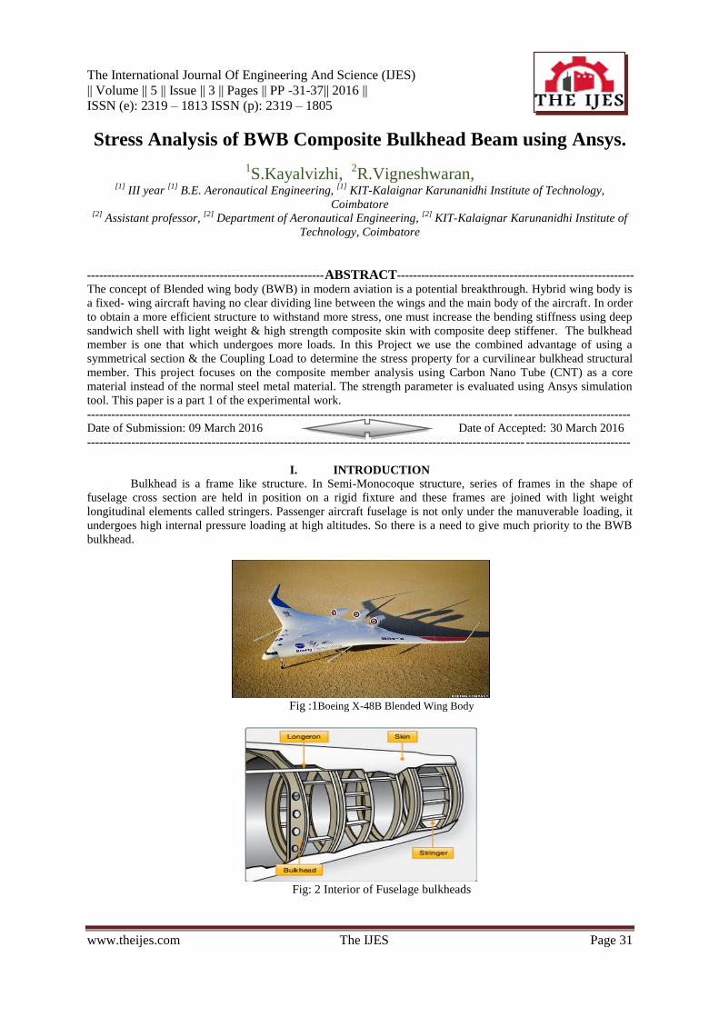
I. INTRODUCTION
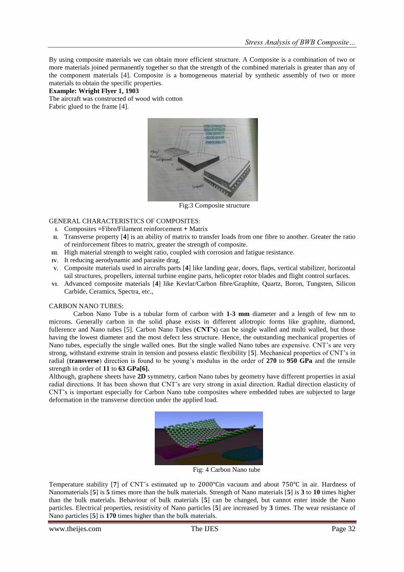
Bulkhead is a frame like structure. In Semi-Monocoque structure, series of frames in the shape of
fuselage cross section are held in position on a rigid fixture and these frames are joined with light weight
longitudinal elements called stringers. Passenger aircraft fuselage is not only under the manuverable loading, it
undergoes high internal pressure loading at high altitudes. So there is a need to give much priority to the BWB
bulkhead.
Fig :1Boeing X-48B Blended Wing Body
Fig: 2 Interior of Fuselage bulkheads
Stress Analysis of BWB Composite…
www.theijes.com The IJES Page 32
By using composite materials we can obtain more efficient structure. A Composite is a combination of two or
more materials joined permanently together so that the strength of the combined materials is greater than any of
the component materials [4]. Composite is a homogeneous material by synthetic assembly of two or more
materials to obtain the specific properties.
Example: Wright Flyer 1, 1903
The aircraft was constructed of wood with cotton
Fabric glued to the frame [4].
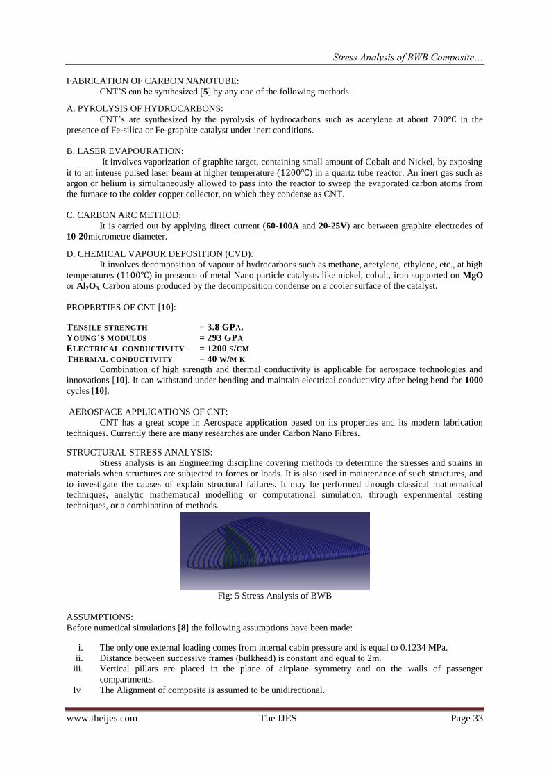
Fig:3 Composite structure
GENERAL CHARACTERISTICS OF COMPOSITES: I. Composites =Fibre/Filament reinforcement + Matrix
II. Transverse property [4] is an ability of matrix to transfer loads from one fibre to another. Greater the ratio
of reinforcement fibres to matrix, greater the strength of composite.
III. High material strength to weight ratio, coupled with corrosion and fatigue resistance.
IV. It reducing aerodynamic and parasite drag.
V. Composite materials used in aircrafts parts [4] like landing gear, doors, flaps, vertical stabilizer, horizontal
tail structures, propellers, internal turbine engine parts, helicopter rotor blades and flight control surfaces.
VI. Advanced composite materials [4] like Kevlar/Carbon fibre/Graphite, Quartz, Boron, Tungsten, Silicon
Carbide, Ceramics, Spectra, etc.,
CARBON NANO TUBES: Carbon Nano Tube is a tubular form of carbon with 1-3 mm diameter and a length of few nm to
microns. Generally carbon in the solid phase exists in different allotropic forms like graphite, diamond,
fullerence and Nano tubes [5]. Carbon Nano Tubes (CNT’s) can be single walled and multi walled, but those
having the lowest diameter and the most defect less structure. Hence, the outstanding mechanical properties of
Nano tubes, especially the single walled ones. But the single walled Nano tubes are expensive. CNT’s are very
strong, withstand extreme strain in tension and possess elastic flexibility [5]. Mechanical properties of CNT’s in
radial (transverse) direction is found to be young’s modulus in the order of 270 to 950 GPa and the tensile
strength in order of 11 to 63 GPa[6]. Although, graphene sheets have 2D symmetry, carbon Nano tubes by geometry have different properties in axial
radial directions. It has been shown that CNT’s are very strong in axial direction. Radial direction elasticity of
CNT’s is important especially for Carbon Nano tube composites where embedded tubes are subjected to large
deformation in the transverse direction under the applied load.
Fig: 4 Carbon Nano tube
Temperature stability [7] of CNT’s estimated up to 2000℃in vacuum and about 750℃ in air. Hardness of
Nanomaterials [5] is 5 times more than the bulk materials. Strength of Nano materials [5] is 3 to 10 times higher
than the bulk materials. Behaviour of bulk materials [5] can be changed, but cannot enter inside the Nano
particles. Electrical properties, resistivity of Nano particles [5] are increased by 3 times. The wear resistance of
Nano particles [5] is 170 times higher than the bulk materials.
Stress Analysis of BWB Composite…
www.theijes.com The IJES Page 33
FABRICATION OF CARBON NANOTUBE:
CNT’S can be synthesized [5] by any one of the following methods.
A. PYROLYSIS OF HYDROCARBONS:
CNT’s are synthesized by the pyrolysis of hydrocarbons such as acetylene at about 700℃ in the
presence of Fe-silica or Fe-graphite catalyst under inert conditions.
B. LASER EVAPOURATION:
It involves vaporization of graphite target, containing small amount of Cobalt and Nickel, by exposing
it to an intense pulsed laser beam at higher temperature (1200℃) in a quartz tube reactor. An inert gas such as
argon or helium is simultaneously allowed to pass into the reactor to sweep the evaporated carbon atoms from
the furnace to the colder copper collector, on which they condense as CNT.
C. CARBON ARC METHOD:
It is carried out by applying direct current (60-100A and 20-25V) arc between graphite electrodes of
10-20micrometre diameter.
D. CHEMICAL VAPOUR DEPOSITION (CVD):
It involves decomposition of vapour of hydrocarbons such as methane, acetylene, ethylene, etc., at high
temperatures (1100℃) in presence of metal Nano particle catalysts like nickel, cobalt, iron supported on MgO
or Al2O3. Carbon atoms produced by the decomposition condense on a cooler surface of the catalyst.
PROPERTIES OF CNT [10]:
TENSILE STRENGTH = 3.8 GPA.
YOUNG’S MODULUS = 293 GPA
ELECTRICAL CONDUCTIVITY = 1200 S/CM
THERMAL CONDUCTIVITY = 40 W/M K
Combination of high strength and thermal conductivity is applicable for aerospace technologies and
innovations [10]. It can withstand under bending and maintain electrical conductivity after being bend for 1000
cycles [10].
AEROSPACE APPLICATIONS OF CNT:
CNT has a great scope in Aerospace application based on its properties and its modern fabrication
techniques. Currently there are many researches are under Carbon Nano Fibres.
STRUCTURAL STRESS ANALYSIS:
Stress analysis is an Engineering discipline covering methods to determine the stresses and strains in
materials when structures are subjected to forces or loads. It is also used in maintenance of such structures, and
to investigate the causes of explain structural failures. It may be performed through classical mathematical
techniques, analytic mathematical modelling or computational simulation, through experimental testing
techniques, or a combination of methods.
Fig: 5 Stress Analysis of BWB
ASSUMPTIONS:
Before numerical simulations [8] the following assumptions have been made:
i. The only one external loading comes from internal cabin pressure and is equal to 0.1234 MPa.
ii. Distance between successive frames (bulkhead) is constant and equal to 2m.
iii. Vertical pillars are placed in the plane of airplane symmetry and on the walls of passenger
compartments.
Iv The Alignment of composite is assumed to be unidirectional.

Stress Analysis of BWB Composite…
www.theijes.com The IJES Page 34
Table: Estimated elastic constants of fiber in Carbon Epoxy Carbon Nano Tube.Composite
S.No Elastic Constant Vf @0.70
1 E1(GPa) 85.14
2 E2(GPa) 85.144
3 E3(GPa) 16.06
4 ɤ12 0.04
5 ɤ23 0.78
6 ɤ13 0.78
7 G12(GPa) 4.36
8 G23(GPa) 4.8
9 G13(GPa) 4.8
SECTION MODULUS:
Section Modulus [9] is a geometric property for a given cross section used in the design of beams or
flexural members. Other geometric properties used in design include area for tension and shear, radius of
compression and moment of inertia and polar moment of inertia for stiffness.
Section Modulus, S = (I / y)
Where,
I =moment of inertia, in mm4.
y =distance from neutral axis to outer surface, in mm.
Types of Section Modulus:
1. Elastic Section Modulus (S)
2. Plastic Section Modulus (Z)
SECTION MODULUS FOR I SECTION BEAM:
When the Neutral Axis N-A passes through the centre and x axis of the beam, then Section modulus,
When the Neutral Axis N-A passes through the centre and y axis of the Beam, then
S.No Are a
m 2
X
mm
Y
mm
X i
mm
Y i
mm
A(X-Xi)2
m m 4
A(Y-Y i)2
m m 4
1 . 14000 1 4 0 2 5 1 4 0 3 0 5 0 109.76E7
2 . 2 0 4 0 1 4 0 3 0 5 1 4 0 3 0 5 0 0
3 . 14000 1 4 0 5 8 5 1 4 0 3 0 5 0 202.16E7
∑ 0 311.92E7
Note:
Keep units consistent for the input design variables in inches or mm. Section Modulus,
THEORETICAL CALCULATION FOR I SECTION:
The given I section is symmetry about both x axis and y axis. If two or more axes of symmetry, then
centroid will coincide with the intersection of these two axis.
Fig: 7 I section of the BWB bulkhead
2 3
6 6
B H b hS
H
32
6 6
B H h h B bS
B
Stress Analysis of BWB Composite…
www.theijes.com The IJES Page 35
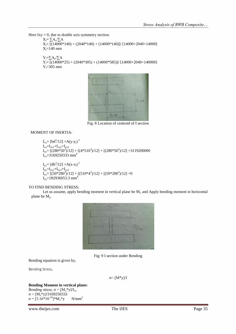
Here Ixy = 0, due to double axis symmetry section.
Xi= ∑Ax/∑A
Xi= [(14000*140) + (2040*140) + (14000*140)]/ [14000+2040+14000]
Xi=140 mm
Yi=∑Ay/∑A
Yi= [(14000*25) + (2040*305) + (14000*585)]/ [14000+2040+140000]
Yi=305 mm
Fig: 8 Location of centroid of I section
MOMENT OF INERTIA:
Ixx= [bd3/12] +A(y-yi)
2
Ixx=Ixx1+Ixx2+Ixx3
Ixx= [(280*503)/12] + [(4*510
3)/12] + [(280*50
3)/12] +3119200000
Ixx=3169250333 mm4
Iyy= [db3/12] +A(x-xi)
2
Iyy=Iyy1+Iyy2+Iyy3
Iyy= [(50*2803)/12] + [(510*4
3)/12] + [(50*280
3)/12] +0
Iyy=182936053.3 mm4
TO FIND BENDING STRESS:
Let us assume, apply bending moment in vertical plane be Mx and Apply bending moment in horizontal
plane be My.
Fig: 9 I section under Bending
Bending equation is given by,
Bending Stress,
σ= [M*y]/I
Bending Moment in vertical plane:
Bending stress, σ = [Mx*y]/Ixx
σ = [Mx*y]/3169250333
σ = [3.16*10-10
]*Mx*y N/mm2
Stress Analysis of BWB Composite…
www.theijes.com The IJES Page 36
Bending Moment in horizontal plane:
Bending stress, σ = [My*y]/Iyy
σ = [My*y]/182936053.3
σ = [5.47*10-9
]*My*y N/mm2
TO FIND SHEAR FLOW:
Now, let us apply the shear load on vertically and horizontally and shear flow will be “q”
For symmetric section,
Shear flow for vertical shear load,
q= −𝒔
𝑰𝒙𝒙 𝒚𝒕𝒅𝒔
Shear flow for horizontal shear load,
q= −𝒔
𝑰𝒚𝒚 𝒙𝒕𝒅𝒔
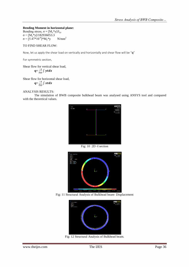
ANALYSIS RESULTS:
The simulation of BWB composite bulkhead beam was analysed using ANSYS tool and compared
with the theoretical values.
Fig: 10 2D -I section
Fig: 11 Structural Analysis of Bulkhead beam- Displacement
Fig: 12 Structural Analysis of Bulkhead beam.
Stress Analysis of BWB Composite…
www.theijes.com The IJES Page 37
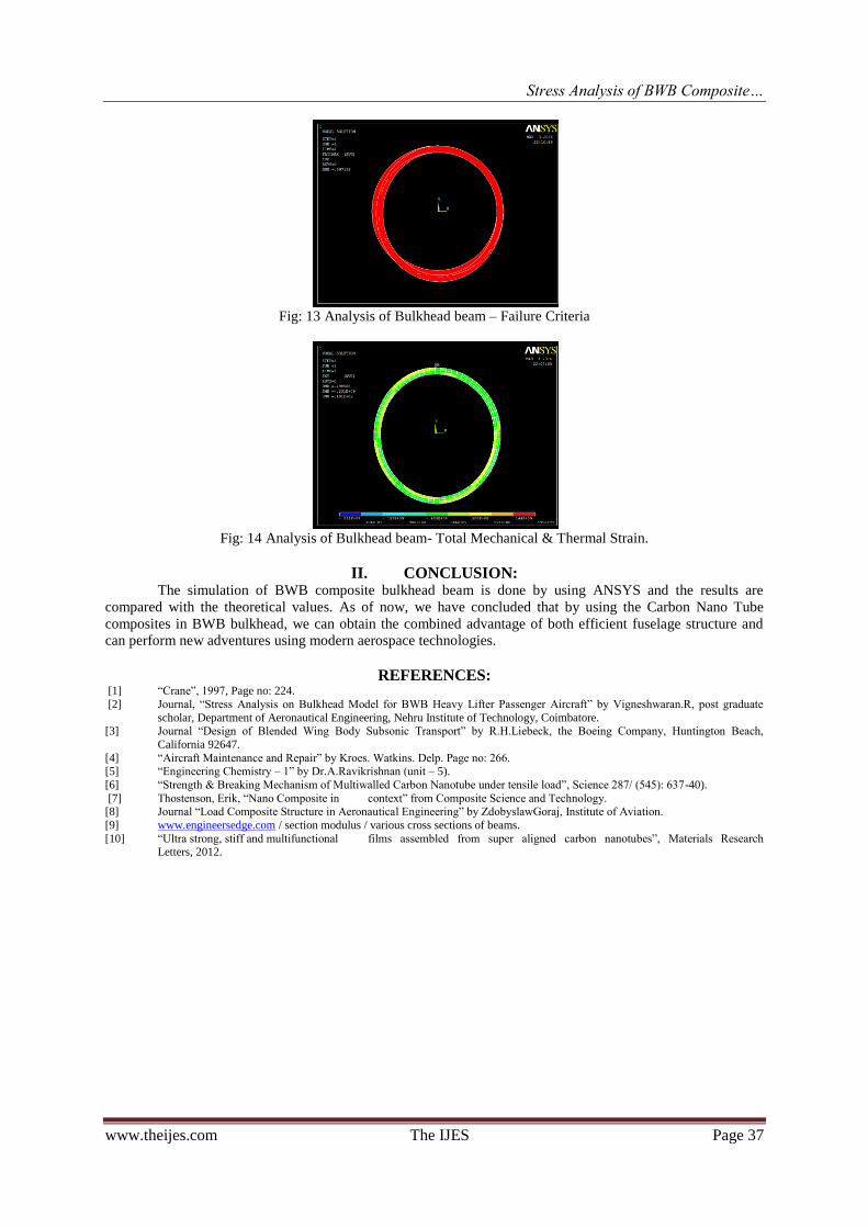
Fig: 13 Analysis of Bulkhead beam – Failure Criteria
Fig: 14 Analysis of Bulkhead beam- Total Mechanical & Thermal Strain.
II. CONCLUSION: The simulation of BWB composite bulkhead beam is done by using ANSYS and the results are
compared with the theoretical values. As of now, we have concluded that by using the Carbon Nano Tube
composites in BWB bulkhead, we can obtain the combined advantage of both efficient fuselage structure and
can perform new adventures using modern aerospace technologies.
REFERENCES: [1] “Crane”, 1997, Page no: 224.
[2] Journal, “Stress Analysis on Bulkhead Model for BWB Heavy Lifter Passenger Aircraft” by Vigneshwaran.R, post graduate
scholar, Department of Aeronautical Engineering, Nehru Institute of Technology, Coimbatore. [3] Journal “Design of Blended Wing Body Subsonic Transport” by R.H.Liebeck, the Boeing Company, Huntington Beach,
California 92647.
[4] “Aircraft Maintenance and Repair” by Kroes. Watkins. Delp. Page no: 266. [5] “Engineering Chemistry – 1” by Dr.A.Ravikrishnan (unit – 5).
[6] “Strength & Breaking Mechanism of Multiwalled Carbon Nanotube under tensile load”, Science 287/ (545): 637-40).
[7] Thostenson, Erik, “Nano Composite in context” from Composite Science and Technology. [8] Journal “Load Composite Structure in Aeronautical Engineering” by ZdobyslawGoraj, Institute of Aviation.
[9] www.engineersedge.com / section modulus / various cross sections of beams.
[10] “Ultra strong, stiff and multifunctional films assembled from super aligned carbon nanotubes”, Materials Research Letters, 2012.