stormwater ponds - connecticut connecticut stormwater quality manual 11-pi-1 stormwater ponds...
TRANSCRIPT
2004 Connecticut Stormwater Quality Manual 11-PI-1
Stormwater Ponds
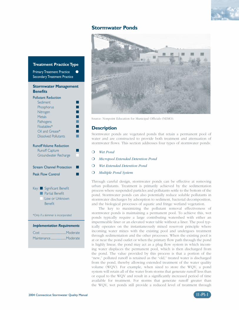
DescriptionStormwater ponds are vegetated ponds that retain a permanent pool ofwater and are constructed to provide both treatment and attenuation ofstormwater flows. This section addresses four types of stormwater ponds:
❍ Wet Pond
❍ Micropool Extended Detention Pond
❍ Wet Extended Detention Pond
❍ Multiple Pond System
Through careful design, stormwater ponds can be effective at removingurban pollutants. Treatment is primarily achieved by the sedimentationprocess where suspended particles and pollutants settle to the bottom of thepond. Stormwater ponds can also potentially reduce soluble pollutants instormwater discharges by adsorption to sediment, bacterial decomposition,and the biological processes of aquatic and fringe wetland vegetation.
The key to maximizing the pollutant removal effectiveness ofstormwater ponds is maintaining a permanent pool. To achieve this, wetponds typically require a large contributing watershed with either animpermeable liner or an elevated water table without a liner. The pool typ-ically operates on the instantaneously mixed reservoir principle whereincoming water mixes with the existing pool and undergoes treatmentthrough sedimentation and the other processes. When the existing pool isat or near the pond outlet or when the primary flow path through the pondis highly linear, the pond may act as a plug flow system in which incom-ing water displaces the permanent pool, which is then discharged from the pond. The value provided by this process is that a portion of the “new,” polluted runoff is retained as the “old,” treated water is dischargedfrom the pond, thereby allowing extended treatment of the water qualityvolume (WQV). For example, when sized to store the WQV, a pond system will retain all of the water from storms that generate runoff less thanor equal to the WQV and result in a significantly increased period of timeavailable for treatment. For storms that generate runoff greater than the WQV, wet ponds still provide a reduced level of treatment through
Treatment Practice Type
Primary Treatment Practice �
Secondary Treatment Practice
Stormwater ManagementBenefitsPollutant Reduction
Sediment �
Phosphorus �
Nitrogen �
Metals �
Pathogens �
Floatables* �
Oil and Grease* �
Dissolved Pollutants �
Runoff Volume ReductionRunoff Capture �
Groundwater Recharge �
Stream Channel Protection �
Peak Flow Control �
Key: � Significant Benefit� Partial Benefit� Low or Unknown
Benefit
*Only if a skimmer is incorporated
Implementation Requirements
Cost ........................................ModerateMaintenance.........................Moderate
Source: Nonpoint Education for Municipal Officials (NEMO).
2004 Connecticut Stormwater Quality Manual11-PI-2
conventional settling and filtration for the additionalrunoff volume that is conveyed through the pond.The pond volume should be greater than or equal tothe WQV to ensure at least one-day retention timewithin the pond.
When properly designed, the permanent poolreduces the velocity of incoming water to preventresuspension of particles and promote settling ofnewly introduced suspended solids. The energy dissi-pating and treatment properties of the permanentpool are enhanced by aquatic vegetation, which is anessential part of the stormwater pond design. In con-trast, dry detention ponds, or dry extended detentionponds that have no permanent pool, are not consid-ered an acceptable option for treating the WQV dueto the potential for resuspension of accumulated sed-iment by incoming storm flows during the earlyportion of a storm event when the pond is empty.
Several design variations of stormwater pondsexist that can fit a wide range of design conditions.Descriptions of these design variations are providedin the following section.
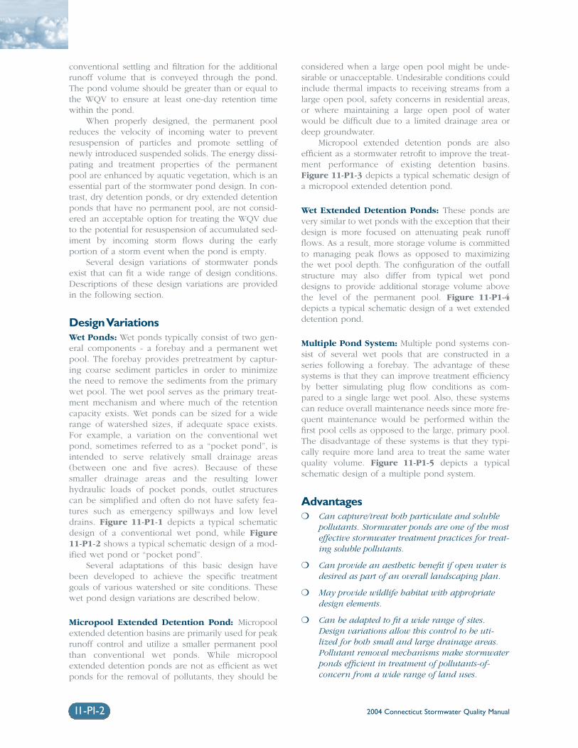
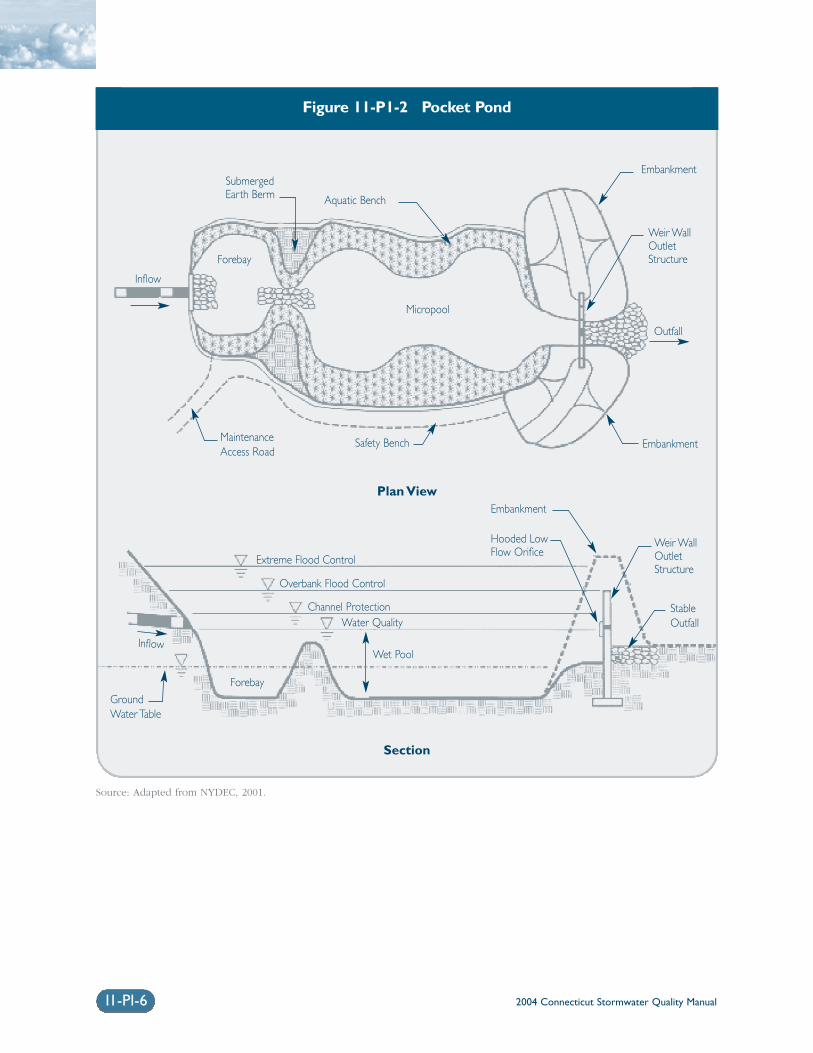
Design VariationsWet Ponds: Wet ponds typically consist of two gen-eral components - a forebay and a permanent wetpool. The forebay provides pretreatment by captur-ing coarse sediment particles in order to minimizethe need to remove the sediments from the primarywet pool. The wet pool serves as the primary treat-ment mechanism and where much of the retentioncapacity exists. Wet ponds can be sized for a widerange of watershed sizes, if adequate space exists.For example, a variation on the conventional wetpond, sometimes referred to as a “pocket pond”, isintended to serve relatively small drainage areas(between one and five acres). Because of thesesmaller drainage areas and the resulting lowerhydraulic loads of pocket ponds, outlet structurescan be simplified and often do not have safety fea-tures such as emergency spillways and low leveldrains. Figure 11-P1-1 depicts a typical schematicdesign of a conventional wet pond, while Figure11-P1-2 shows a typical schematic design of a mod-ified wet pond or “pocket pond”.
Several adaptations of this basic design havebeen developed to achieve the specific treatmentgoals of various watershed or site conditions. Thesewet pond design variations are described below.
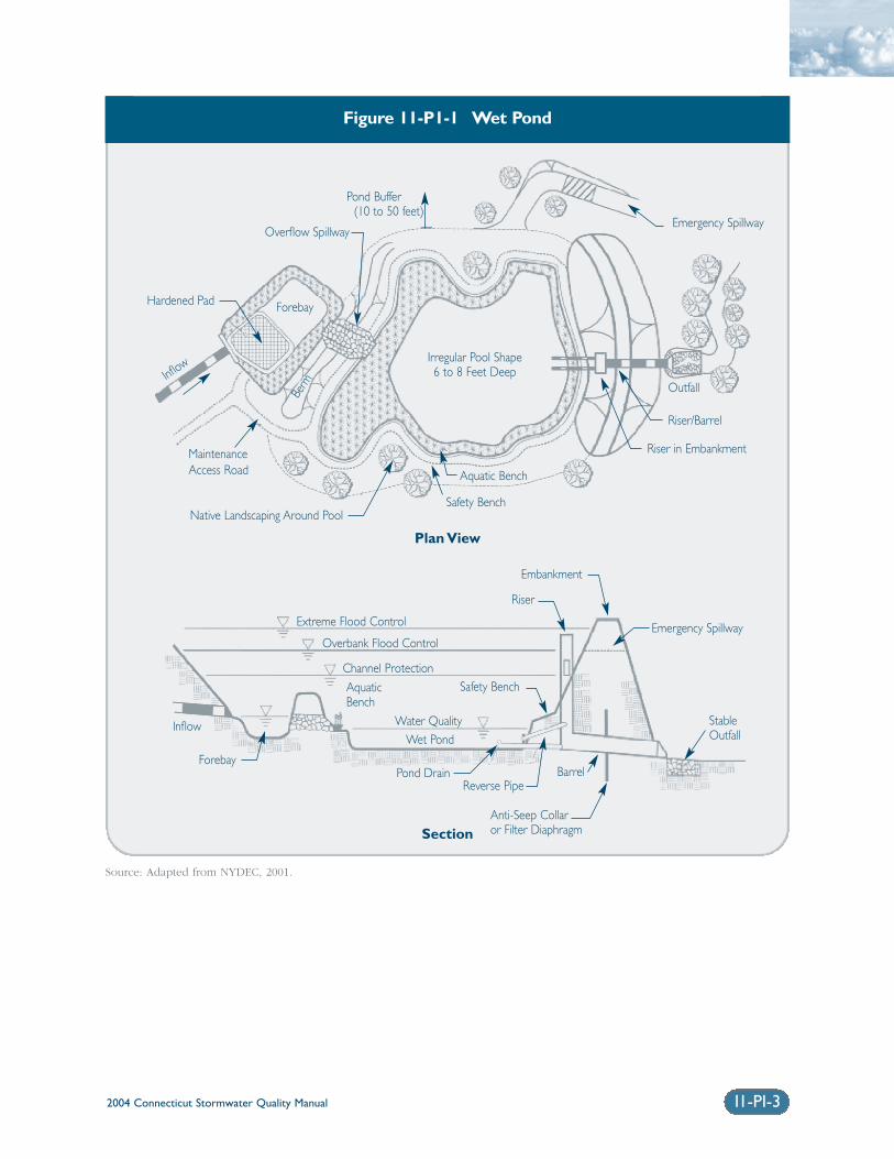
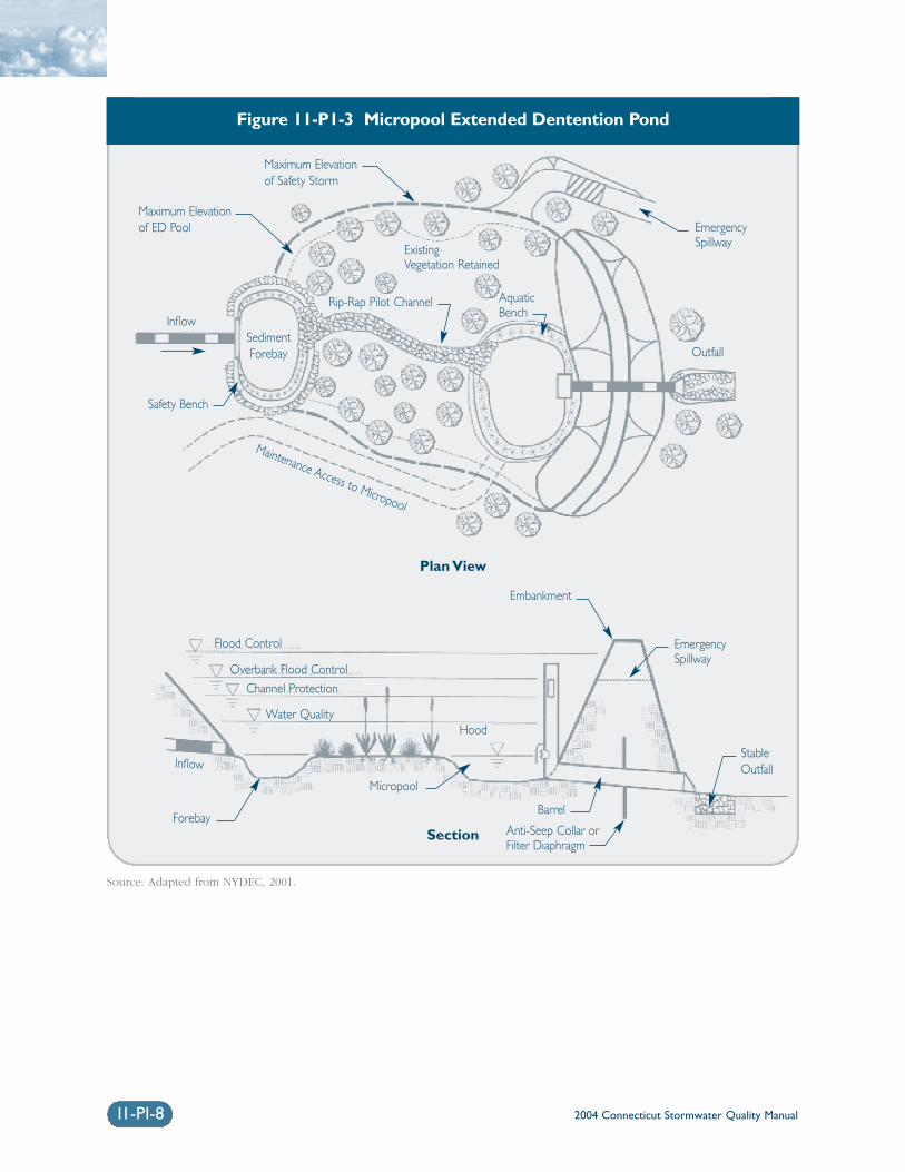
Micropool Extended Detention Pond: Micropoolextended detention basins are primarily used for peakrunoff control and utilize a smaller permanent poolthan conventional wet ponds. While micropoolextended detention ponds are not as efficient as wetponds for the removal of pollutants, they should be
considered when a large open pool might be unde-sirable or unacceptable. Undesirable conditions couldinclude thermal impacts to receiving streams from alarge open pool, safety concerns in residential areas,or where maintaining a large open pool of waterwould be difficult due to a limited drainage area ordeep groundwater.
Micropool extended detention ponds are alsoefficient as a stormwater retrofit to improve the treat-ment performance of existing detention basins.Figure 11-P1-3 depicts a typical schematic design ofa micropool extended detention pond.
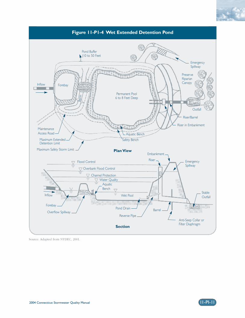
Wet Extended Detention Ponds: These ponds arevery similar to wet ponds with the exception that theirdesign is more focused on attenuating peak runoffflows. As a result, more storage volume is committedto managing peak flows as opposed to maximizingthe wet pool depth. The configuration of the outfallstructure may also differ from typical wet ponddesigns to provide additional storage volume abovethe level of the permanent pool. Figure 11-P1-4depicts a typical schematic design of a wet extendeddetention pond.
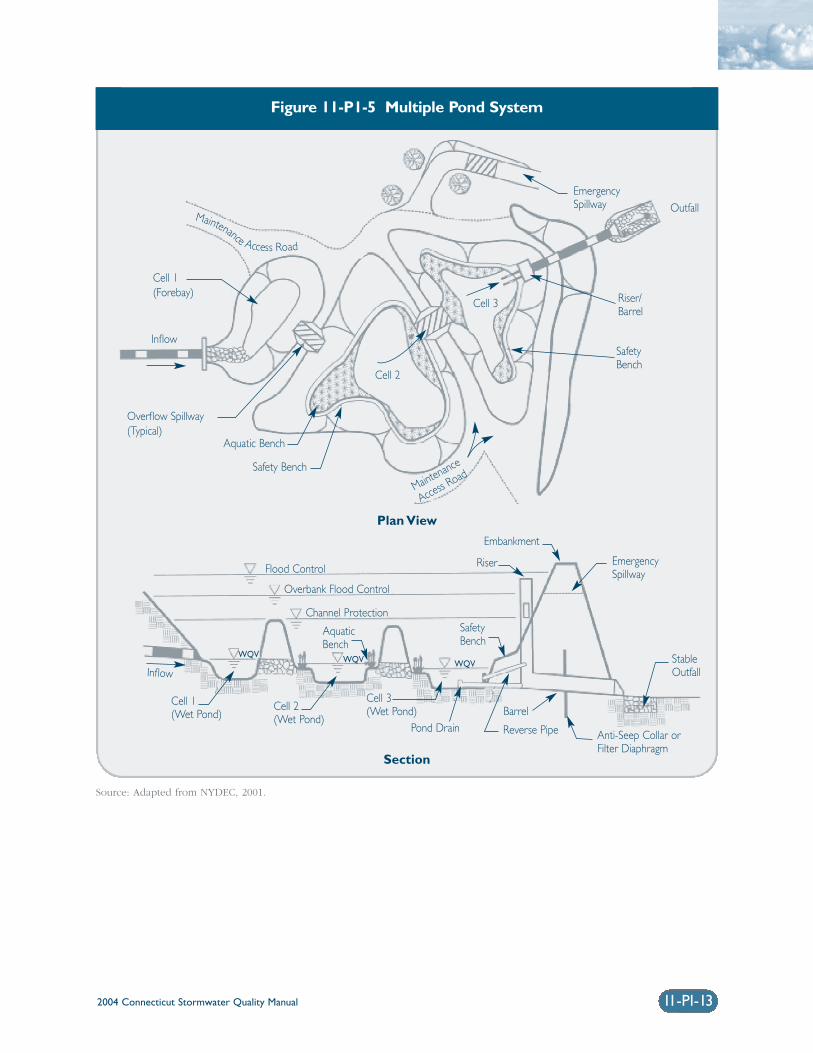
Multiple Pond System: Multiple pond systems con-sist of several wet pools that are constructed in aseries following a forebay. The advantage of thesesystems is that they can improve treatment efficiencyby better simulating plug flow conditions as com-pared to a single large wet pool. Also, these systemscan reduce overall maintenance needs since more fre-quent maintenance would be performed within thefirst pool cells as opposed to the large, primary pool.The disadvantage of these systems is that they typi-cally require more land area to treat the same waterquality volume. Figure 11-P1-5 depicts a typicalschematic design of a multiple pond system.
Advantages❍ Can capture/treat both particulate and soluble
pollutants. Stormwater ponds are one of the mosteffective stormwater treatment practices for treat-ing soluble pollutants.
❍ Can provide an aesthetic benefit if open water isdesired as part of an overall landscaping plan.
❍ May provide wildlife habitat with appropriatedesign elements.
❍ Can be adapted to fit a wide range of sites.Design variations allow this control to be uti-lized for both small and large drainage areas.Pollutant removal mechanisms make stormwaterponds efficient in treatment of pollutants-of-concern from a wide range of land uses.
2004 Connecticut Stormwater Quality Manual 11-PI-3
Figure 11-P1-1 Wet Pond
Source: Adapted from NYDEC, 2001.
Pond Buffer(10 to 50 feet)
Hardened Pad
Overflow Spillway
MaintenanceAccess Road
Native Landscaping Around Pool
Aquatic Bench
Safety Bench
Riser in Embankment
Riser/Barrel
Outfall
Emergency Spillway
Irregular Pool Shape6 to 8 Feet Deep
Forebay
Plan View
Section
Embankment
Riser
Emergency Spillway
StableOutfall
Anti-Seep Collar or Filter Diaphragm
BarrelReverse Pipe
Pond Drain
Extreme Flood Control
Overbank Flood Control
Channel ProtectionSafety Bench
Water QualityWet Pond
AquaticBench
Forebay
Inflow
Inflow
Berm
2004 Connecticut Stormwater Quality Manual11-PI-4
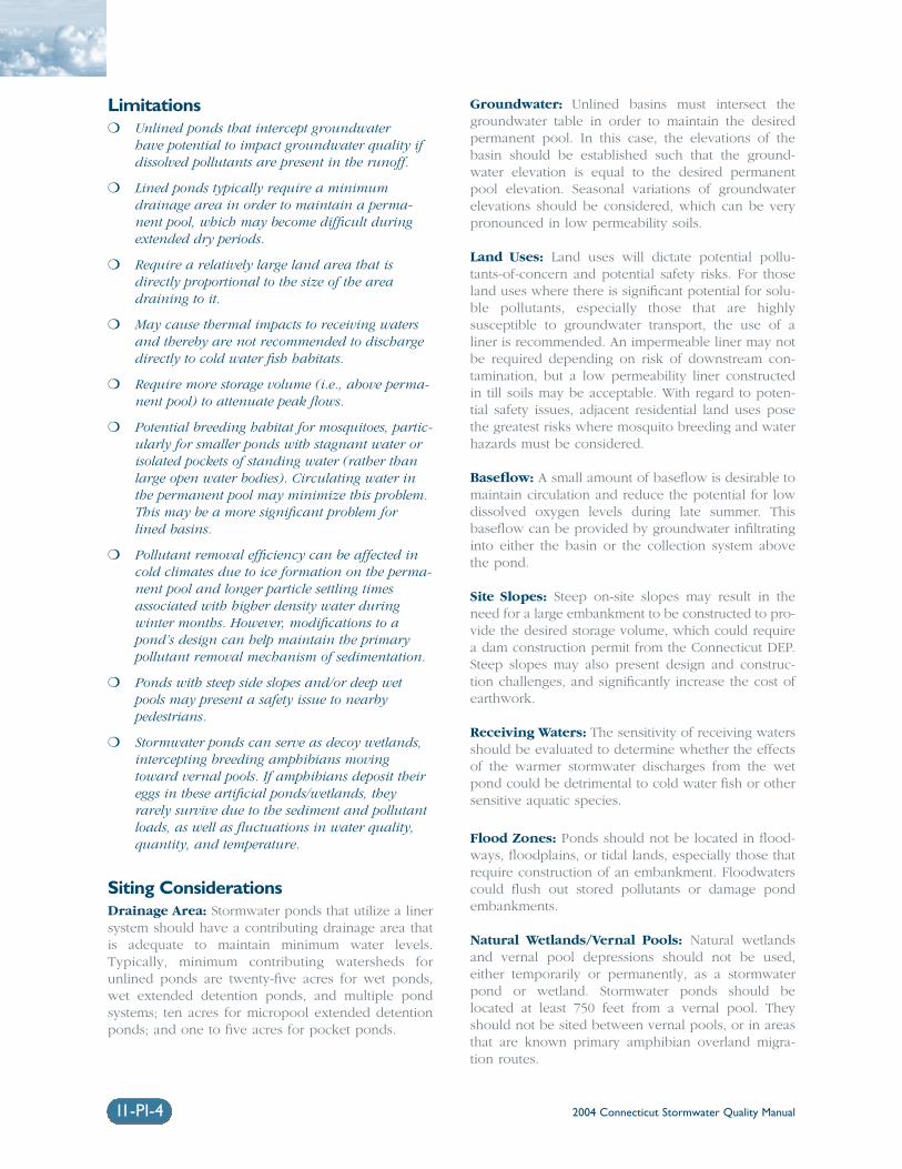
Limitations❍ Unlined ponds that intercept groundwater
have potential to impact groundwater quality ifdissolved pollutants are present in the runoff.
❍ Lined ponds typically require a minimumdrainage area in order to maintain a perma-nent pool, which may become difficult duringextended dry periods.
❍ Require a relatively large land area that isdirectly proportional to the size of the areadraining to it.
❍ May cause thermal impacts to receiving watersand thereby are not recommended to dischargedirectly to cold water fish habitats.
❍ Require more storage volume (i.e., above perma-nent pool) to attenuate peak flows.
❍ Potential breeding habitat for mosquitoes, partic-ularly for smaller ponds with stagnant water orisolated pockets of standing water (rather thanlarge open water bodies). Circulating water inthe permanent pool may minimize this problem.This may be a more significant problem forlined basins.
❍ Pollutant removal efficiency can be affected incold climates due to ice formation on the perma-nent pool and longer particle settling timesassociated with higher density water during winter months. However, modifications to apond’s design can help maintain the primarypollutant removal mechanism of sedimentation.
❍ Ponds with steep side slopes and/or deep wetpools may present a safety issue to nearby pedestrians.
❍ Stormwater ponds can serve as decoy wetlands,intercepting breeding amphibians movingtoward vernal pools. If amphibians deposit theireggs in these artificial ponds/wetlands, theyrarely survive due to the sediment and pollutantloads, as well as fluctuations in water quality,quantity, and temperature.
Siting ConsiderationsDrainage Area: Stormwater ponds that utilize a linersystem should have a contributing drainage area thatis adequate to maintain minimum water levels.Typically, minimum contributing watersheds forunlined ponds are twenty-five acres for wet ponds,wet extended detention ponds, and multiple pondsystems; ten acres for micropool extended detentionponds; and one to five acres for pocket ponds.
Groundwater: Unlined basins must intersect thegroundwater table in order to maintain the desiredpermanent pool. In this case, the elevations of thebasin should be established such that the ground-water elevation is equal to the desired permanentpool elevation. Seasonal variations of groundwaterelevations should be considered, which can be verypronounced in low permeability soils.
Land Uses: Land uses will dictate potential pollu-tants-of-concern and potential safety risks. For thoseland uses where there is significant potential for solu-ble pollutants, especially those that are highlysusceptible to groundwater transport, the use of aliner is recommended. An impermeable liner may notbe required depending on risk of downstream con-tamination, but a low permeability liner constructedin till soils may be acceptable. With regard to poten-tial safety issues, adjacent residential land uses posethe greatest risks where mosquito breeding and waterhazards must be considered.
Baseflow: A small amount of baseflow is desirable tomaintain circulation and reduce the potential for lowdissolved oxygen levels during late summer. Thisbaseflow can be provided by groundwater infiltratinginto either the basin or the collection system abovethe pond.
Site Slopes: Steep on-site slopes may result in theneed for a large embankment to be constructed to pro-vide the desired storage volume, which could requirea dam construction permit from the Connecticut DEP.Steep slopes may also present design and construc-tion challenges, and significantly increase the cost ofearthwork.
Receiving Waters: The sensitivity of receiving watersshould be evaluated to determine whether the effectsof the warmer stormwater discharges from the wetpond could be detrimental to cold water fish or othersensitive aquatic species.
Flood Zones: Ponds should not be located in flood-ways, floodplains, or tidal lands, especially those thatrequire construction of an embankment. Floodwaterscould flush out stored pollutants or damage pondembankments.
Natural Wetlands/Vernal Pools: Natural wetlandsand vernal pool depressions should not be used,either temporarily or permanently, as a stormwaterpond or wetland. Stormwater ponds should belocated at least 750 feet from a vernal pool. Theyshould not be sited between vernal pools, or in areasthat are known primary amphibian overland migra-tion routes.
2004 Connecticut Stormwater Quality Manual
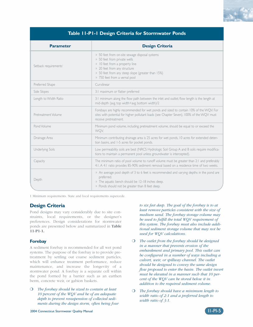
Design CriteriaPond designs may vary considerably due to site con-straints, local requirements, or the designer’spreferences. Design considerations for stormwaterponds are presented below and summarized in Table11-P1-1.
ForebayA sediment forebay is recommended for all wet pondsystems. The purpose of the forebay is to provide pre-treatment by settling out coarse sediment particles,which will enhance treatment performance, reducemaintenance, and increase the longevity of astormwater pond. A forebay is a separate cell withinthe pond formed by a barrier such as an earthenberm, concrete weir, or gabion baskets.
❍ The forebay should be sized to contain at least10 percent of the WQV and be of an adequatedepth to prevent resuspension of collected sedi-ments during the design storm, often being four
to six feet deep. The goal of the forebay is to atleast remove particles consistent with the size ofmedium sand. The forebay storage volume maybe used to fulfill the total WQV requirement ofthis system. The forebay must also include addi-tional sediment storage volume that may not beused for WQV calculations.
❍ The outlet from the forebay should be designedin a manner that prevents erosion of theembankment and primary pool. This outlet canbe configured in a number of ways including aculvert, weir, or spillway channel. The outletshould be designed to convey the same designflow proposed to enter the basin. The outlet invertmust be elevated in a manner such that 10 per-cent of the WQV can be stored below it inaddition to the required sediment volume.
❍ The forebay should have a minimum length towidth ratio of 2:1 and a preferred length towidth ratio of 3:1.
11-PI-5
Parameter Design Criteria
Setback requirements1
Preferred Shape
Side Slopes
Length to Width Ratio
Pretreatment Volume
Pond Volume
Drainage Area
Underlying Soils
Capacity
Depth
❍ 50 feet from on-site sewage disposal systems❍ 50 feet from private wells❍ 10 feet from a property line❍ 20 feet from any structure❍ 50 feet from any steep slope (greater than 15%)❍ 750 feet from a vernal pool
Curvilinear
3:1 maximum or flatter preferred
3:1 minimum along the flow path between the inlet and outlet; flow length is the length atmid-depth (avg. top width+avg. bottom width)/2
Forebays are highly recommended for wet ponds and sized to contain 10% of the WQV. Forsites with potential for higher pollutant loads (see Chapter Seven), 100% of the WQV mustreceive pretreatment.
Minimum pond volume, including pretreatment volume, should be equal to or exceed theWQV.
Minimum contributing drainage area is 25 acres for wet ponds, 10 acres for extended deten-tion basins, and 1-5 acres for pocket ponds.
Low permeability soils are best (NRCS Hydrologic Soil Group A and B soils require modifica-tions to maintain a permanent pool unless groundwater is intercepted).
The minimum ratio of pool volume to runoff volume must be greater than 2:1 and preferably4:1. A 4:1 ratio provides 85-90% sediment removal based on a residence time of two weeks.
❍ An average pool depth of 3 to 6 feet is recommended and varying depths in the pond arepreferred.
❍ The aquatic bench should be 12-18 inches deep.❍ Ponds should not be greater than 8 feet deep.
Table 11-P1-1 Design Criteria for Stormwater Ponds
1 Minimum requirements. State and local requirements supercede.
2004 Connecticut Stormwater Quality Manual11-PI-6
Figure 11-P1-2 Pocket Pond
Source: Adapted from NYDEC, 2001.
SubmergedEarth Berm
MaintenanceAccess Road
Safety Bench
Aquatic Bench
Micropool
Embankment
Outfall
Extreme Flood Control
Overbank Flood Control
Channel ProtectionWater Quality
Forebay
Inflow
Plan View
Section
Embankment
Weir WallOutlet Structure
Wet Pool
Forebay
Inflow
GroundWater Table
Weir WallOutlet Structure
Embankment
StableOutfall
Hooded LowFlow Orifice
❍ Direct access for appropriate maintenanceequipment should be provided to the forebayand may include a ramp to the bottom if equip-ment cannot reach all points within the forebayfrom the top. The forebay can be lined with aconcrete pad to allow easy removal of sedimentand to minimize the possibility of excavatingsubsurface soils or undercutting embankmentsduring routine maintenance.
❍ A fixed vertical sediment depth marker should beinstalled in the forebay to measure sedimentdeposition.
❍ A barrier, such as an earthen berm, gabions, or a concrete weir may be used to separate theforebay from the permanent pool. This barriershould be armored as necessary to prevent erosion of the embankment if it overtops. Thisarmoring could consist of materials such asriprap, pavers, or geosynthetics designed to resistslope erosion. If a channel is used to conveyflows from the forebay to the pond, the sideslopes of the channel must be armored as well.
❍ Additional pretreatment can be provided in theforebay by raising the embankment to providesome detention of incoming flows.
Wet Pool Stormwater pond design features primarily enhancethe removal of pollutants by increasing the residencetime of stormwater in the pond and providing habitatfor aquatic plants.
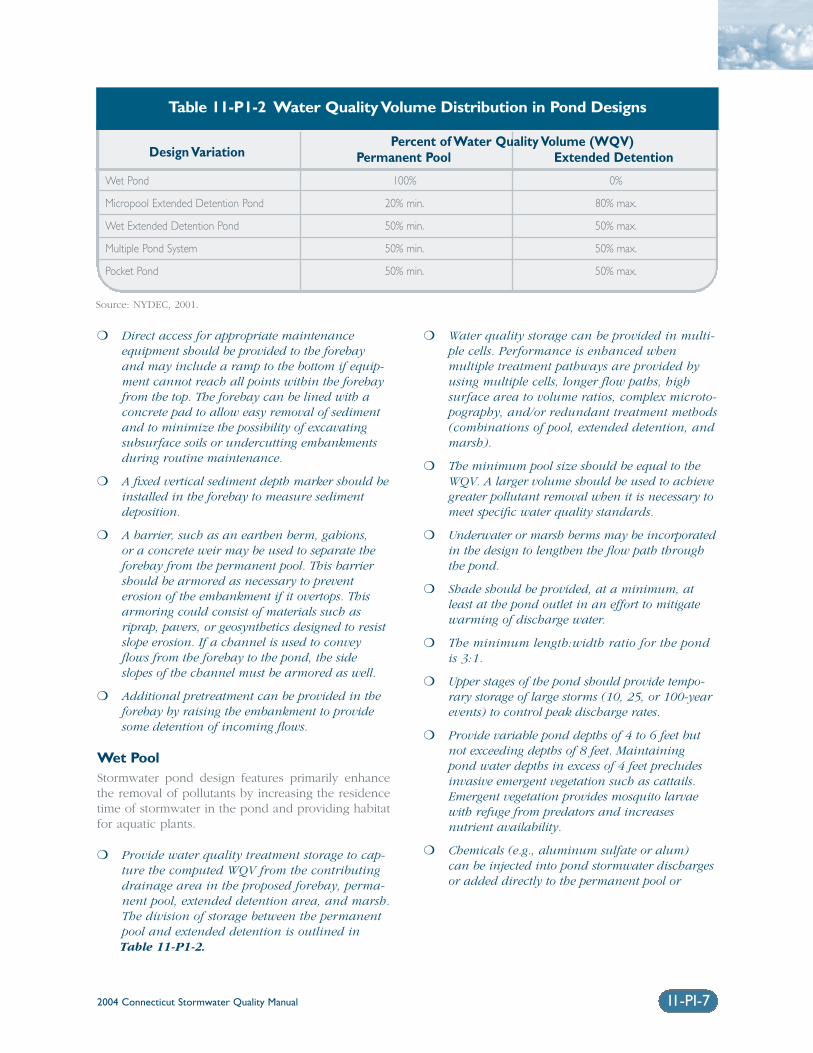
❍ Provide water quality treatment storage to cap-ture the computed WQV from the contributingdrainage area in the proposed forebay, perma-nent pool, extended detention area, and marsh.The division of storage between the permanentpool and extended detention is outlined inTable 11-P1-2.
❍ Water quality storage can be provided in multi-ple cells. Performance is enhanced whenmultiple treatment pathways are provided byusing multiple cells, longer flow paths, high surface area to volume ratios, complex microto-pography, and/or redundant treatment methods(combinations of pool, extended detention, andmarsh).
❍ The minimum pool size should be equal to theWQV. A larger volume should be used to achievegreater pollutant removal when it is necessary tomeet specific water quality standards.
❍ Underwater or marsh berms may be incorporatedin the design to lengthen the flow path throughthe pond.
❍ Shade should be provided, at a minimum, atleast at the pond outlet in an effort to mitigatewarming of discharge water.
❍ The minimum length:width ratio for the pondis 3:1.
❍ Upper stages of the pond should provide tempo-rary storage of large storms (10, 25, or 100-yearevents) to control peak discharge rates.
❍ Provide variable pond depths of 4 to 6 feet butnot exceeding depths of 8 feet. Maintainingpond water depths in excess of 4 feet precludesinvasive emergent vegetation such as cattails.Emergent vegetation provides mosquito larvaewith refuge from predators and increases nutrient availability.
❍ Chemicals (e.g., aluminum sulfate or alum) can be injected into pond stormwater dischargesor added directly to the permanent pool or
Design VariationPercent of Water Quality Volume (WQV)
Permanent Pool Extended Detention
Wet Pond 100% 0%
Micropool Extended Detention Pond 20% min. 80% max.
Wet Extended Detention Pond 50% min. 50% max.
Multiple Pond System 50% min. 50% max.
Pocket Pond 50% min. 50% max.
Table 11-P1-2 Water Quality Volume Distribution in Pond Designs
Source: NYDEC, 2001.
2004 Connecticut Stormwater Quality Manual 11-PI-7
2004 Connecticut Stormwater Quality Manual11-PI-8
Figure 11-P1-3 Micropool Extended Dentention Pond
Source: Adapted from NYDEC, 2001.
ExistingVegetation Retained
Maximum Elevationof Safety Storm
Safety Bench
AquaticBench
Barrel
Outfall
Flood Control
Overbank Flood ControlChannel Protection
Water Quality
SedimentForebay
Inflow
Plan View
Section
Embankment
Micropool
Forebay
InflowStableOutfall
EmergencySpillway
Maintenance Access to Micropool
EmergencySpillway
Maximum Elevationof ED Pool
Hood
Rip-Rap Pilot Channel
Anti-Seep Collar orFilter Diaphragm
2004 Connecticut Stormwater Quality Manual 11-PI-9
sediment forebay to enhance removal of fineparticulates and dissolved pollutants within the pond.
❍ Maintain pond water quality sufficient to supportmosquito-feeding fish. Stormwater ponds oftendevelop mini-ecosystems where birds, frogs, andother insects feed, many of which are naturalpredators of mosquitoes and nuisance insects.Ponds can also be stocked with predatory fishnative to Connecticut that feed on mosquito larvae such as banded sunfish, flathead minnows,Eastern mud minnows, and several species ofkillfish. The DEP Fisheries Division should beconsulted regarding species selection. Other natural predators of mosquitoes such as dragon-fly nymphs can also be used.
Conveyance Stormwater should be conveyed to and from allstormwater management practices safely and to mini-mize erosion potential.
Inlet Protection❍ The number of inlets should be minimized and
one inlet is preferable. The inlet should belocated at the most hydraulically remote pointfrom the outlet to minimize the potential forshort-circuiting, and should be located in amanner that meets or exceeds desired length towidth ratios.
❍ Inlet areas should be stabilized to ensure thatnon-erosive conditions exist for the design storm event.
❍ The ideal inlet configuration is above the permanent pool to prevent potential hydraulicconstrictions due to freezing.
Outlet Protection
❍ The channel immediately below a pond outfallshould be modified to prevent erosion and con-form to natural topography by use of a plungepool or a riprap pad and sized for peak dis-charge velocities.
❍ Outlet protection should be used to reduce flowto non-erosive velocities from the principal spill-way based on actual cover and soil conditions.
❍ If a pond outlet discharges to a perennial streamor channel with dry weather base flow, treeclearing should be minimized and a forestedriparian zone re-established.
❍ To convey potential flood flows from the basin,an armored emergency spillway should be provided.
Pond Liners❍ When a pond is located such that the permanent
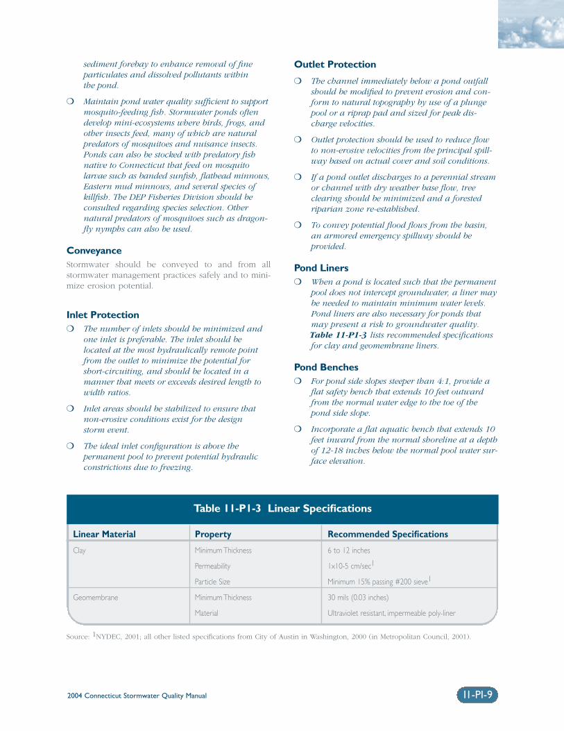
pool does not intercept groundwater, a liner maybe needed to maintain minimum water levels.Pond liners are also necessary for ponds thatmay present a risk to groundwater quality.Table 11-P1-3 lists recommended specificationsfor clay and geomembrane liners.
Pond Benches❍ For pond side slopes steeper than 4:1, provide a
flat safety bench that extends 10 feet outwardfrom the normal water edge to the toe of thepond side slope.
❍ Incorporate a flat aquatic bench that extends 10feet inward from the normal shoreline at a depthof 12-18 inches below the normal pool water sur-face elevation.
Linear Material Property Recommended Specifications
Clay Minimum Thickness 6 to 12 inches
Permeability 1x10⁻⁵ cm/sec1
Particle Size Minimum 15% passing #200 sieve1
Geomembrane Minimum Thickness 30 mils (0.03 inches)
Material Ultraviolet resistant, impermeable poly-liner
Table 11-P1-3 Linear Specifications
Source: 1NYDEC, 2001; all other listed specifications from City of Austin in Washington, 2000 (in Metropolitan Council, 2001).
2004 Connecticut Stormwater Quality Manual11-PI-10
Maintenance Reduction FeaturesIn addition to regular maintenance activities needed tomaintain the function of stormwater practices, somedesign features can be incorporated to ease the main-tenance burden of each practice. In wet ponds,maintenance reduction features include techniques to reduce the amount of maintenance needed, as wellas techniques to make regular maintenance activitieseasier.
❍ Ponds should be designed with non-clogging out-lets, such as a weir, or by incorporating trashracks for culverts and orifice openings.
❍ To prevent clogging from ice or floatables, areverse slope outlet pipe can be used to drawwater from below the permanent pool up to theoutlet structure. The invert of the pipe drawingfrom the pool should be at least 18 inches fromthe bottom to prevent sediment discharge.
❍ No orifice should be less than 6 inches in diameter with a trash rack to prevent clogging.
❍ Ponds should have a manually operated drain to draw down the pond for infrequent mainte-nance or dredging of the main cell of the pond.
❍ Metal components of outlet structures should becorrosion resistant, but not galvanized due to the contribution of zinc to water.
❍ Outlet structures should be resistant to frostheave and ice action in the pond.
Landscaping Constructing landscaped wet ponds can enhance theiraesthetic value. Aquatic plantings around the edge ofthe pond can provide pollutant uptake, stabilize thesoil at the edge of the pond, and improve habitat.Maintaining high vegetation along the edge of thepond (not mowing to the edge) can also deter water-fowl access and filter pollutants.
❍ Wetland plantings should be encouraged in apond design, either along the aquatic bench(fringe wetlands), the safety bench and sideslopes, or within shallow areas of the pool.
❍ The best depth for establishing wetland plants,either through transplantation or volunteer colo-nization, is within approximately six inches ofthe normal pool elevation.
❍ Soils should be modified (e.g., scarified or tilled)to mitigate compaction that occurs during con-struction around the proposed planting sites.
❍ Avoid species that require full shade, are suscep-tible to winterkill, or are prone to wind damage.
❍ Woody vegetation may not be planted or allowedto grow within 25 feet of the toe of the embank-ment and 25 feet from the principal spillwaystructure.
❍ Existing trees should be preserved in the bufferarea during construction. It is desirable to locateforest conservation areas adjacent to ponds. Tohelp discourage resident geese populations, the buffer can be planted with trees, shrubs, andnative ground covers.
❍ Annual mowing of the pond buffer is onlyrequired along maintenance rights-of-way andthe embankment. The remaining buffer can bemanaged as a meadow (mowing every otheryear) or forest.
❍ Plant the pond with salt-tolerant vegetation if thestormwater pond receives road runoff.
Cold Climate Pond Design ConsiderationsThe following design elements should be consideredto minimize potential performance impacts caused bycold weather:
❍ Inlet pipes should not be submerged, since thiscan result in freezing and upstream damage orflooding.
❍ Bury all pipes below the frost line to prevent frostheave and pipe freezing. Bury pipes at the pointfurthest from the pond deeper than the frost lineto minimize the length of pipe exposed.
❍ Increase the slope of inlet pipes to a minimum of1 percent, if site conditions allow, to preventstanding water in the pipe and reduce the poten-tial for ice formation.
❍ If perforated riser pipes are used, the minimumorifice diameter should be 0.5 inches. In addi-tion, the pipe should have a diameter of at least6 inches.
❍ When a standard weir is used, the minimum slotwidth should be 3 inches, especially when the slotis tall.
❍ Baffle weirs can prevent ice formation near theoutlet by preventing surface ice from blockingthe inlet, encouraging the movement of base flowthrough the system.
❍ In cold climates, riser hoods and reverse slopepipes should draw from at least 6 inches belowthe typical ice layer. This design encourages cir-culation in the pond, preventing stratificationand formation of ice at the outlet. Reverse slopepipes should not be used for off-line ponds.
11-PI-11
Figure 11-P1-4 Wet Extended Detention Pond
Source: Adapted from NYDEC, 2001.
Permanent Pool6 to 8 Feet Deep
PreserveRiparianCanopy
Barrel
Outfall
Flood Control
Overbank Flood Control
Channel ProtectionWater Quality
ForebayInflow
Plan View
Section
Embankment
Reverse Pipe
Forebay
InflowStableOutfall
EmergencySpillway
EmergencySpillway
Maximum ExtendedDetention Limit
Riser
Overflow Spillway
Anti-Seep Collar orFilter Diaphragm
MaintenanceAccess Road Aquatic Bench
Safety Bench
Riser in Embankment
Riser/Barrel
Maximum Safety Storm Limit
Berm
Pond Buffer(10 to 50 Feet
Pond Drain
Wet Pool
AquaticBench
2004 Connecticut Stormwater Quality Manual
2004 Connecticut Stormwater Quality Manual
❍ Trash racks should be installed at a shallowangle to prevent ice formation.
❍ Additional storage should be provided to accountfor storage lost to ice buildup. Ice thickness maybe estimated by consulting with local authorities(e.g. the fire department) with knowledge of thetypical ice thickness in the area.
Construction❍ Any stormwater treatment practices that create
an embankment, including stormwater ponds,are under the jurisdiction of the Dam SafetySection of the Connecticut DEP Inland WaterResources Division (IWRD) and should be constructed, inspected, and maintained inaccordance with Connecticut General Statutes§§22a-401 through 22a-411, inclusive, andapplicable DEP guidance.
❍ Avoid soil compaction to promote growth of vegetation.
❍ Temporary erosion and sediment controls shouldbe used during construction and sedimentdeposited in the stormwater pond should beremoved after construction.
❍ Appropriate soil stabilization methods should beused before permanent vegetation is established.Seeding, sodding, and other temporary soil stabilization controls should be implemented inaccordance with the Connecticut Guidelines forSoil Erosion and Sediment Control.
❍ Temporary dewatering may be required if excavation extends below the water table.Appropriate sedimentation controls will berequired for any dewatering discharges.
Inspection and Maintenance❍ Plans for stormwater ponds should identify
detailed inspection and maintenance require-ments, inspection and maintenance schedules,and those parties responsible for maintenance.
❍ The principal spillway should be equipped with a removable trash rack, and generally accessiblefrom dry land.
❍ Sediment removal in the forebay should occur at a minimum of every five years or after thesediment storage capacity in the forebay capacity has been filled.
11-PI-12
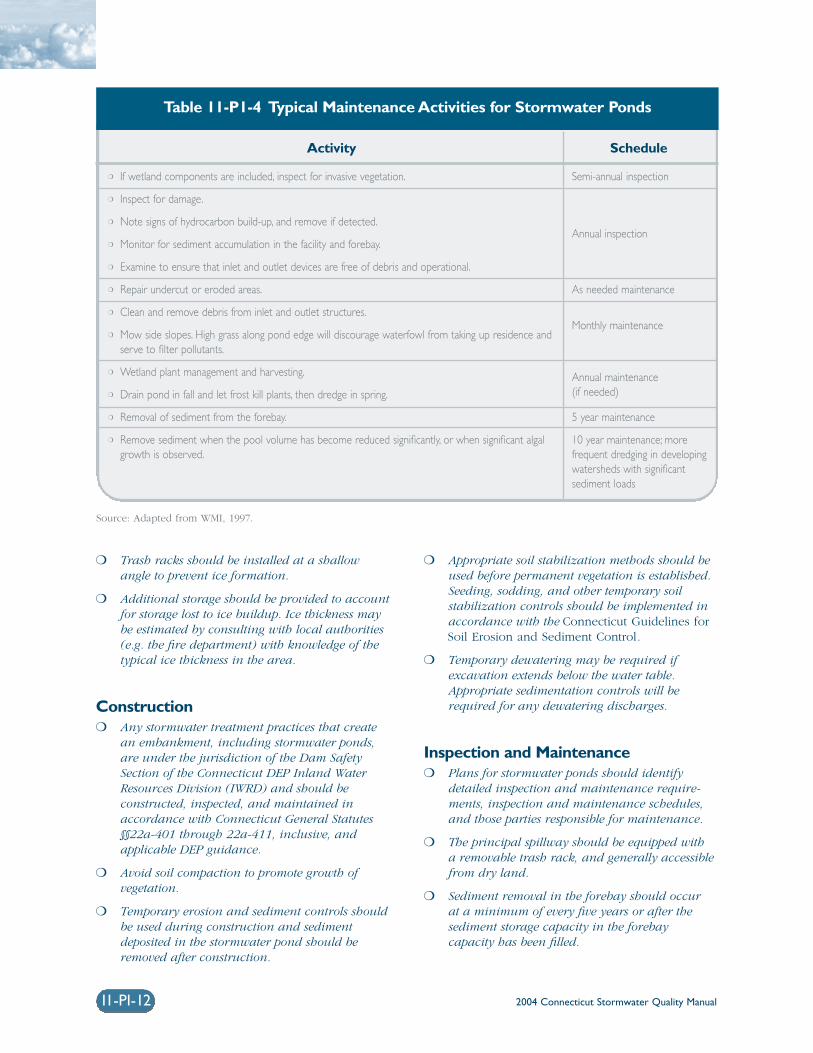
Activity Schedule
❍ If wetland components are included, inspect for invasive vegetation.
❍ Inspect for damage.
❍ Note signs of hydrocarbon build-up, and remove if detected.
❍ Monitor for sediment accumulation in the facility and forebay.
❍ Examine to ensure that inlet and outlet devices are free of debris and operational.
❍ Repair undercut or eroded areas.
❍ Clean and remove debris from inlet and outlet structures.
❍ Mow side slopes. High grass along pond edge will discourage waterfowl from taking up residence andserve to filter pollutants.
❍ Wetland plant management and harvesting.
❍ Drain pond in fall and let frost kill plants, then dredge in spring.
❍ Removal of sediment from the forebay.
❍ Remove sediment when the pool volume has become reduced significantly, or when significant algalgrowth is observed.
Semi-annual inspection
Annual inspection
As needed maintenance
Monthly maintenance
Annual maintenance(if needed)
5 year maintenance
10 year maintenance; more frequent dredging in developingwatersheds with significant sediment loads
Table 11-P1-4 Typical Maintenance Activities for Stormwater Ponds
Source: Adapted from WMI, 1997.
2004 Connecticut Stormwater Quality Manual 11-PI-13
Figure 11-P1-5 Multiple Pond System
Source: Adapted from NYDEC, 2001.
Maintenance
Access Road
Safety Bench
AquaticBench
Riser
Outfall
Flood Control
Overbank Flood Control
Channel Protection
Inflow
Plan View
Section
Embankment
InflowStableOutfall
EmergencySpillway
EmergencySpillway
Anti-Seep Collar orFilter Diaphragm
Reverse PipePond Drain
Cell 3(Wet Pond)
WQV WQV
SafetyBench
Cell 2(Wet Pond)
Cell 1(Wet Pond) Barrel
WQV
Aquatic Bench
Overflow Spillway(Typical)
Cell 1(Forebay)
Maintenance Access Road
Cell 2
Cell 3 Riser/Barrel
SafetyBench
2004 Connecticut Stormwater Quality Manual11-PI-14
❍ Sediment removed from stormwater pondsshould be disposed of according to anapproved comprehensive operation andmaintenance plan.
❍ Recommended maintenance activities forstormwater ponds are summarized in Table 11-P1-4.
Maintenance Access❍ A maintenance right-of-way or easement should
extend to the pond from a public road.
❍ Maintenance access should be at least 12 feetwide, have a maximum slope of no more than15 percent, and be appropriately stabilized towithstand maintenance equipment and vehicles.
❍ The maintenance access should extend to theforebay, safety bench, riser, and outlet and bedesigned to allow vehicles to turn around.
Non-clogging Low Flow Orifice❍ A low flow orifice shall be provided, with the size
of the orifice sufficient to ensure that no cloggingwill occur.
❍ The low flow orifice should be adequately pro-tected from clogging by either an acceptableexternal trash rack (recommended minimumorifice of 6 inches) or by internal orifice protec-tion that may allow for smaller diameters(minimum of 1 inch).
❍ The preferred method is a submerged reverse-slope pipe that extends downward from the riserto an inflow point one foot below the normalpool elevation.
❍ Alternative methods are to employ a broadcrested rectangular, V-notch, or proportionalweir, protected by a half-round pipe that extendsat least 12 inches below the normal pool level.
❍ The use of horizontally extended perforated pipeprotected by geotextile fabric and gravel is notrecommended. Vertical pipes may be used as analternative if a permanent pool is present.
Riser in Embankment❍ The riser must be located within the embank-
ment for maintenance access, safety andaesthetics.
❍ Lockable manhole covers and manhole stepswithin easy reach of valves and other controlsshould provide access to the riser. The principalspillway opening should be “fenced” with pipe at8-inch intervals for safety purposes.
Pond Drain❍ Except where local slopes prohibit this design,
each pond should have a drain pipe that cancompletely or partially drain the pond. Thedrain pipe shall have an elbow or protectedintake within the pond to prevent sediment depo-sition in the pipe, and a diameter capable ofdraining the pond within 24 hours.
❍ Pond retention times can be increased toenhance water quality control during stormevents by maintaining ponds at low levels beforestorms and increasing the available pond volumeduring storms.
❍ Care should be exercised during pond drainingto prevent rapid drawdown and minimizedownstream discharge of sediments or anoxicwater. The approving jurisdiction should be notified before draining a pond.
Adjustable Gate Valve❍ Both the WQV extended detention pipe and the
pond drain may be equipped with an adjustablegate valve, typically a handwheel activated knifegate valve.
❍ Valves should be located inside of the riser at apoint where they will not normally be inundatedand can be operated in a safe manner.
❍ Both the WQV extended detention pipe and thepond drain should be sized one pipe size greaterthan the calculated design diameter.
❍ To prevent vandalism, the handwheel should bechained to a ringbolt, manhole step, or otherfixed object.
2004 Connecticut Stormwater Quality Manual
Safety Features❍ Side slopes to the pond should not exceed 3:1
and should terminate at a safety bench.
❍ The principal spillway opening must not permitaccess by small children, and endwalls abovepipe outfalls greater than 48 inches in diametermust be fenced to prevent a hazard.
❍ Both the safety bench and the aquatic benchmay be landscaped to prevent access to the pool.
❍ Warning signs prohibiting swimming and skatingshould be posted.
❍ Pond fencing is generally not encouraged, butmay be required by some municipalities. Thepreferred method is to grade the pond to elimi-nate dropoffs or other safety hazards.
Cost Considerations Wet ponds are relatively inexpensive stormwater prac-tices, but costs vary widely depending on thecomplexity of the design or difficulty of site con-straints. The costs of stormwater ponds may beestimated using the following equation (Brown andSchueler, 1997):
C = 24.5V 0.705
where: C = Construction, design, and permitting cost. V = Volume in the pond to include the
10-year storm (ft3).
Costs should be adjusted for inflation to reflect currentcosts. The annual cost of routine maintenance is typi-cally estimated at about 3 to 5 percent of theconstruction cost (EPA Wet Pond Fact Sheet,http://www.epa.gov/npdes/menuofbmps/menu.htm).Ponds typically have a design life longer than twentyyears.
ReferencesBrown, W. and Shueler, T. 1997. The Economics ofStormwater BMPs in the Mid-Atlantic Region. Centerfor Watershed Protection. Elliot City, MD.
Galli, F. 1990. Thermal Impacts Associated withUrbanization and Stormwater Best ManagementPractices. Metropolitan Washington Council ofGovernments. Prepared for: Maryland Department ofthe Environment. Baltimore, MD.
Metropolitan Council. 2001. Minnesota Urban SmallSites BMP Manual: Stormwater Best ManagementPractices for Cold Climates. Prepared by BarrEngineering Company. St. Paul, Minnesota.
New York State Department of EnvironmentalConservation (NYDEC). 2001. New York StateStormwater Management Design Manual. Preparedby Center for Watershed Protection. Albany, NewYork.
Oberts, G. 1994. Performance of Stormwater Pondsand Wetlands in Winter. Watershed ProtectionTechniques 1(2): 64-68.
Schueler, T. 1997. Influence of Groundwater onPerformance of Stormwater Ponds in Florida.Watershed Protection Techniques 2(4): 525-528.
United States[E1] Environmental Protection Agency(EPA). 2002. National Menu of Best ManagementPractices for Stormwater Phase II. URL:http://www.epa.gov/npdes/menuofbmps/menu.htm,Last Modified January 24, 2002.
Washington State Department of Ecology(Washington). 2000. Stormwater ManagementManual for Western Washington, Final Draft.Olympia, Washington.
Watershed Management Institute (WMI). 1997.Operation, Maintenance, and Management ofStormwater Management Systems. Prepared for U.S.Environmental Protection Agency. Office of Water.Washington, D.C.
11-PI-15