stm32 f4 series - Компэл · presentation highlights the stm32 f4 seriesthe stm32 f4 series...
TRANSCRIPT
STM32 F4 series
High-performance Cortex™-M4 MCU
Presentation highlights
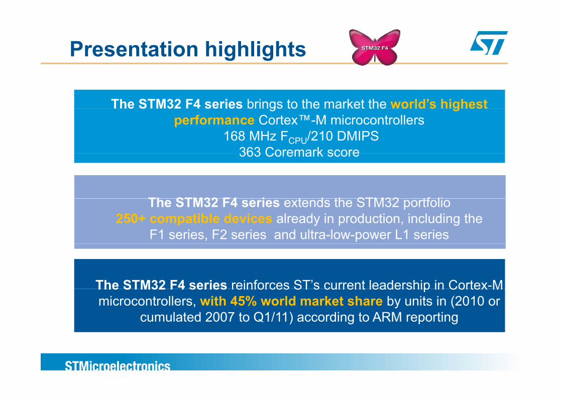
The STM32 F4 series brings to the market the world’s highestThe STM32 F4 series brings to the market the world s highest performance Cortex™-M microcontrollers
168 MHz FCPU/210 DMIPS363 Coremark score363 Coremark score
Th STM32 F4 i t d th STM32 tf liThe STM32 F4 series extends the STM32 portfolio 250+ compatible devices already in production, including the
F1 series, F2 series and ultra-low-power L1 series
The STM32 F4 series reinforces ST’s current leadership in Cortex-MThe STM32 F4 series reinforces ST s current leadership in Cortex M microcontrollers, with 45% world market share by units in (2010 or
cumulated 2007 to Q1/11) according to ARM reporting
STM32 F4 series – applications served
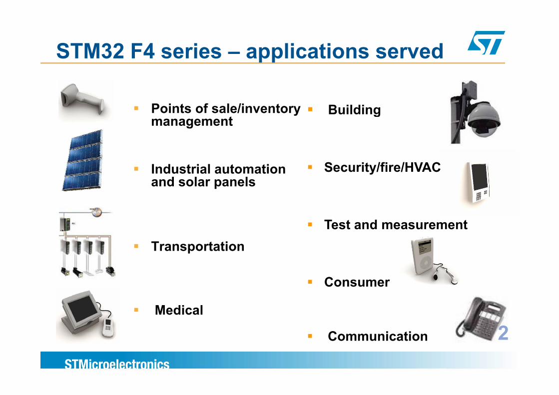
Points of sale/inventory BuildingPoints of sale/inventory management
Building
Industrial automation and solar panels
Security/fire/HVAC
T t tiTest and measurement
Transportation
Consumer
Medical
C i ti 2Communication 2
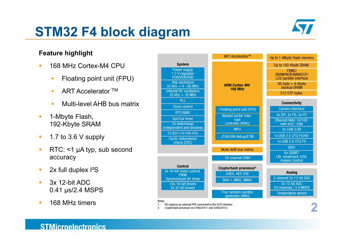
STM32 F4 block diagramFeature highlight
168 MHz Cortex-M4 CPU168 MHz Cortex M4 CPU
Floating point unit (FPU)
ART Accelerator TM
Multi-level AHB bus matrix
1-Mbyte Flash, 192 Kbyte SRAM192-Kbyte SRAM
1.7 to 3.6 V supply
RTC: <1 µA typ sub secondRTC: <1 µA typ, sub second accuracy
2x full duplex I²S
3x 12-bit ADC 0.41 µs/2.4 MSPS
168 MHz timers 22
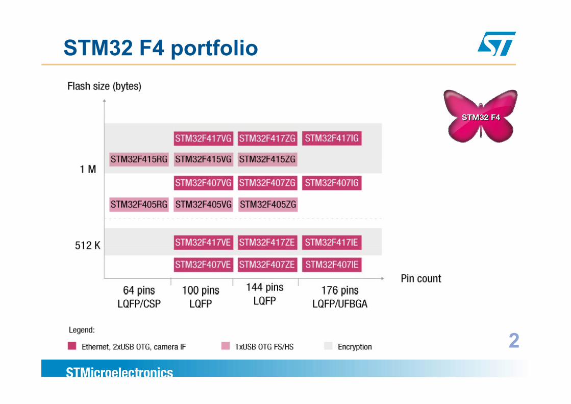
STM32 F4 portfolio
22
STM32 F4 key featuresSTM32 F4 key features
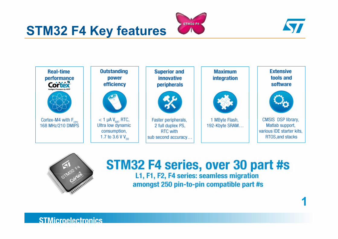
STM32 F4 Key features
11
Real time performanceReal time performance
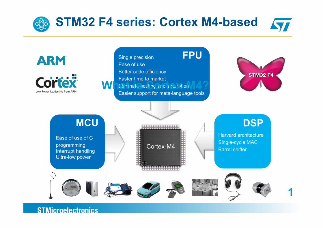
STM32 F4 series: Cortex M4-based
Single precision FPUEase of useBetter code efficiencyFaster time to marketEliminate scaling and saturationWhat is Cortex-M4?gEasier support for meta-language tools
What is Cortex M4?
Harvard architecture
DSPEase of use of C
MCU
Single-cycle MACBarrel shifter
programmingInterrupt handlingUltra-low power
Cortex-M4
11
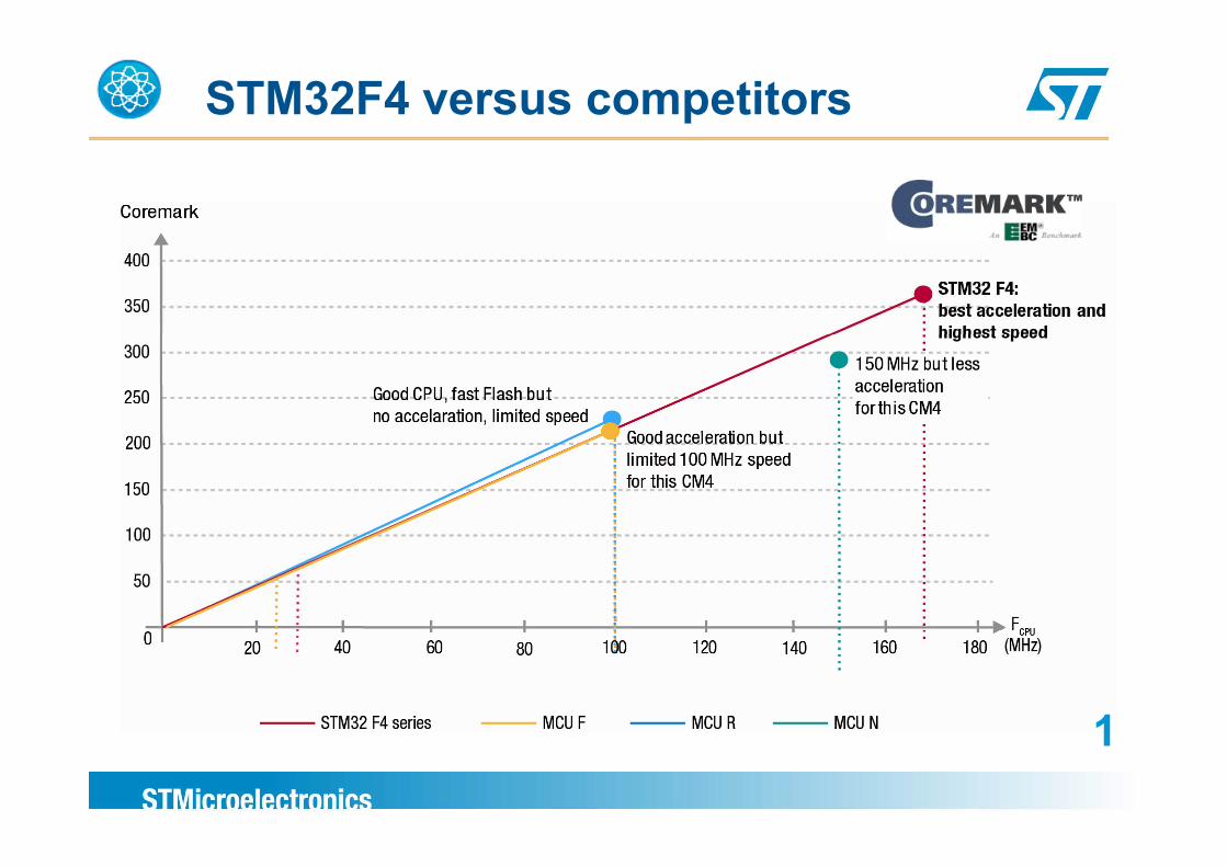
STM32F4 versus competitors
11
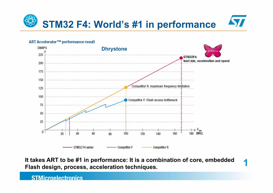
STM32 F4: World’s #1 in performance
Dhrystone
It takes ART to be #1 in performance: It is a combination of core, embedded 1p ,Flash design, process, acceleration techniques. 1
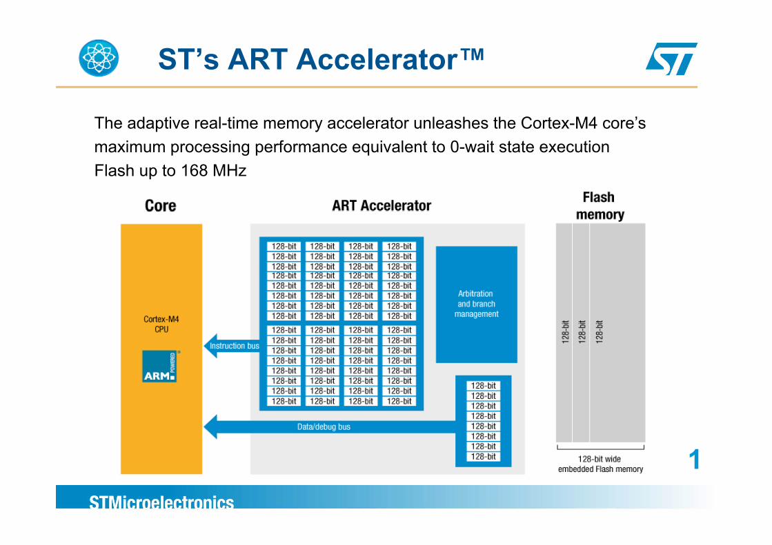
ST’s ART Accelerator™
The adaptive real-time memory accelerator unleashes the Cortex-M4 core’smaximum processing performance equivalent to 0-wait state executionmaximum processing performance equivalent to 0 wait state executionFlash up to 168 MHz
11
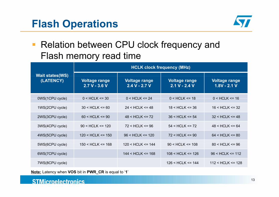
Flash Operations
Relation between CPU clock frequency and Fl h d tiFlash memory read time
Wait states(WS)
HCLK clock frequency (MHz)
Wait states(WS)(LATENCY) Voltage range
2.7 V - 3.6 VVoltage range2.4 V - 2.7 V
Voltage range2.1 V - 2.4 V
Voltage range1.8V - 2.1 V
0WS(1CPU cycle) 0 < HCLK <= 30 0 < HCLK <= 24 0 < HCLK <= 18 0 < HCLK <= 160WS(1CPU cycle) 0 < HCLK <= 30 0 < HCLK <= 24 0 < HCLK <= 18 0 < HCLK <= 16
1WS(2CPU cycle) 30 < HCLK <= 60 24 < HCLK <= 48 18 < HCLK <= 36 16 < HCLK <= 32
2WS(3CPU cycle) 60 < HCLK <= 90 48 < HCLK <= 72 36 < HCLK <= 54 32 < HCLK <= 48
3WS(4CPU cycle) 90 < HCLK <= 120 72 < HCLK <= 96 54 < HCLK <= 72 48 < HCLK <= 64
4WS(5CPU cycle) 120 < HCLK <= 150 96 < HCLK <= 120 72 < HCLK <= 90 64 < HCLK <= 80
5WS(6CPU l ) 150 HCLK 168 120 HCLK 144 90 HCLK 108 80 HCLK 965WS(6CPU cycle) 150 < HCLK <= 168 120 < HCLK <= 144 90 < HCLK <= 108 80 < HCLK <= 96
6WS(7CPU cycle) 144 < HCLK <= 168 108 < HCLK <= 126 96 < HCLK <= 112
7WS(8CPU cycle) 126 < HCLK <= 144 112 < HCLK <= 128
Note: Latency when VOS bit in PWR_CR is equal to ‘1’
13
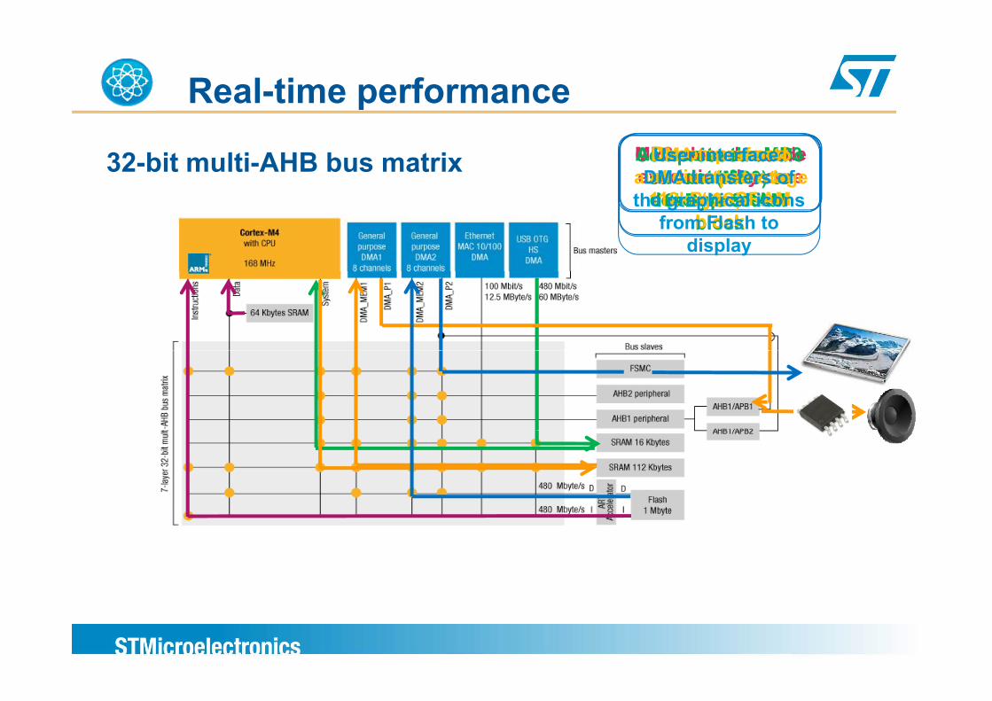
Real-time performance
32-bit multi-AHB bus matrix Compressed audio stream (MP3) to
MP3 decoder code execution by coreAccess to the MP3
data for Decompressed audio stream to DMA transfer to
audio output stage User interface:
DMA transfers of 16kByte SRAM
blockdecompression112kByte SRAM
block(I2S)the graphical icons
from Flash to display
Outstanding power efficiencyOutstanding power efficiency
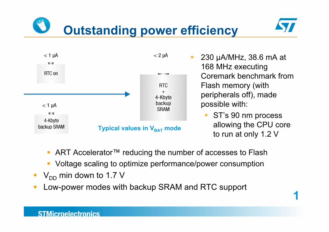
Outstanding power efficiencyg y
230 μA/MHz, 38.6 mA at 168 MHz executing Coremark benchmark from Flash memory (with peripherals off), made possible with:
ST’s 90 nm processTypical values in VBAT mode
ST s 90 nm process allowing the CPU core to run at only 1.2 V
ART Accelerator™ reducing the number of accesses to FlashVoltage scaling to optimize performance/power consumption
VDD min down to 1.7 VLow-power modes with backup SRAM and RTC support
11
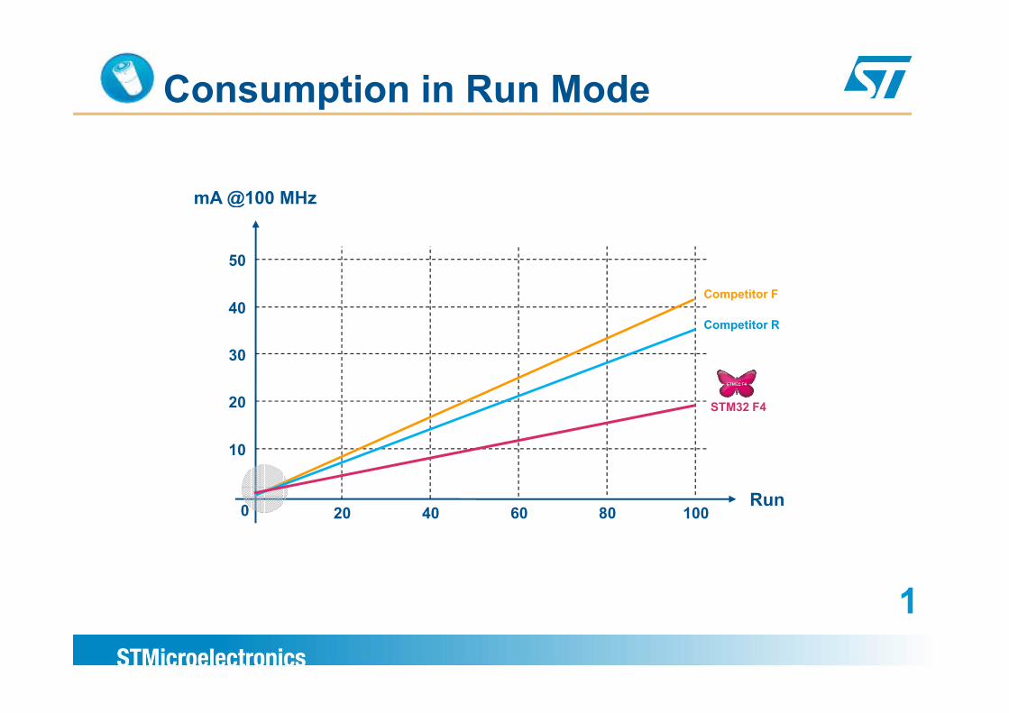
Consumption in Run Mode
mA @100 MHzmA @100 MHz
50
40
30
Competitor F
Competitor R
20
30
STM32 F4
10
0 20 40 60 80 100Run
20 40 60 80 100
11
Superior and innovative peripheralsSuperior and innovative peripherals
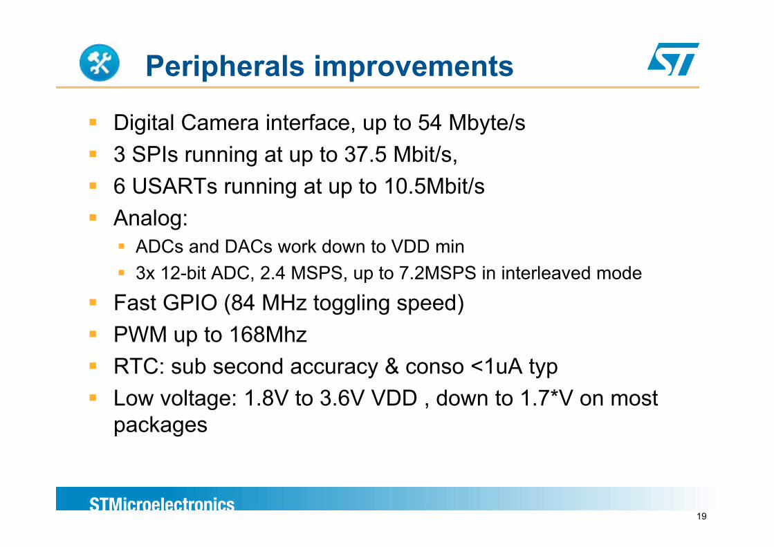
Peripherals improvements
Digital Camera interface, up to 54 Mbyte/s3 SPI i t t 37 5 Mbit/3 SPIs running at up to 37.5 Mbit/s, 6 USARTs running at up to 10.5Mbit/sA lAnalog:
ADCs and DACs work down to VDD min3x 12 bit ADC 2 4 MSPS up to 7 2MSPS in interleaved mode3x 12-bit ADC, 2.4 MSPS, up to 7.2MSPS in interleaved mode
Fast GPIO (84 MHz toggling speed)PWM up to 168MhzPWM up to 168MhzRTC: sub second accuracy & conso <1uA typLow voltage: 1 8V to 3 6V VDD down to 1 7*V on mostLow voltage: 1.8V to 3.6V VDD , down to 1.7 V on most packages
19
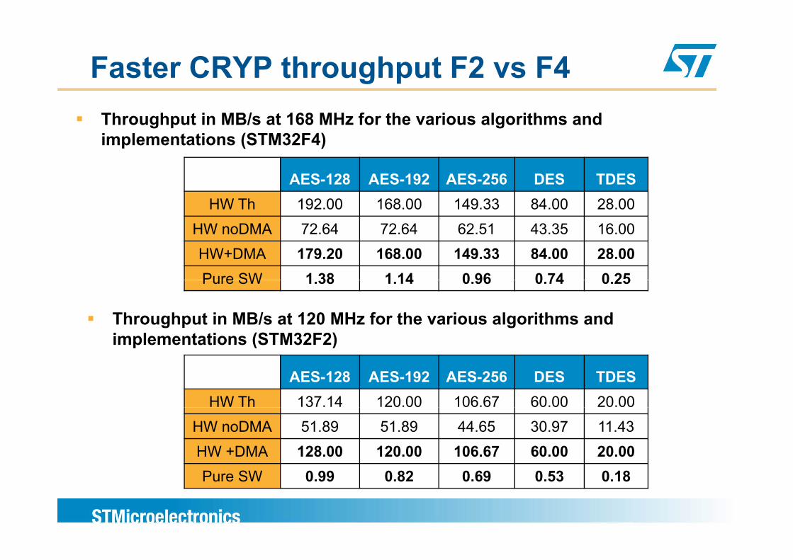
Faster CRYP throughput F2 vs F4Throughput in MB/s at 168 MHz for the various algorithms and implementations (STM32F4)
AES-128 AES-192 AES-256 DES TDESHW Th 192.00 168.00 149.33 84.00 28.00
HW noDMA 72.64 72.64 62.51 43.35 16.00HW+DMA 179.20 168.00 149.33 84.00 28.00Pure SW 1 38 1 14 0 96 0 74 0 25Pure SW 1.38 1.14 0.96 0.74 0.25
Throughput in MB/s at 120 MHz for the various algorithms and implementations (STM32F2)
AES-128 AES-192 AES-256 DES TDESHW Th 137.14 120.00 106.67 60.00 20.00
implementations (STM32F2)
HW noDMA 51.89 51.89 44.65 30.97 11.43HW +DMA 128.00 120.00 106.67 60.00 20.00P SW 0 99 0 82 0 69 0 3 0 18Pure SW 0.99 0.82 0.69 0.53 0.18
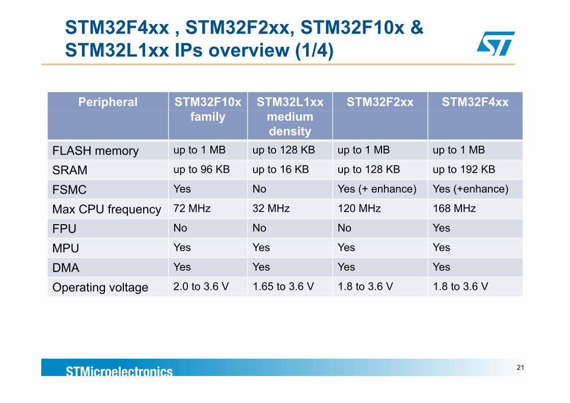
STM32F4xx , STM32F2xx, STM32F10x & STM32L1xx IPs overview (1/4)
Peripheral STM32F10x STM32L1xx STM32F2xx STM32F4xx family medium
density FLASH memory up to 1 MB up to 128 KB up to 1 MB up to 1 MBySRAM up to 96 KB up to 16 KB up to 128 KB up to 192 KB
FSMC Yes No Yes (+ enhance) Yes (+enhance)
Max CPU frequency 72 MHz 32 MHz 120 MHz 168 MHz
FPU No No No Yes
MPU Yes Yes Yes YesMPU Yes Yes Yes Yes
DMA Yes Yes Yes Yes
Operating voltage 2.0 to 3.6 V 1.65 to 3.6 V 1.8 to 3.6 V 1.8 to 3.6 Vp g g
21
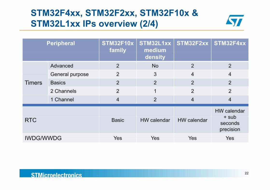
STM32F4xx, STM32F2xx, STM32F10x & STM32L1xx IPs overview (2/4)
Peripheral STM32F10x family
STM32L1xx medium
STM32F2xx STM32F4xx family medium
density Advanced 2 No 2 2General purpose 2 3 4 4
TimersGeneral purpose 2 3 4 4Basics 2 2 2 22 Channels 2 1 2 21 Channel 4 2 4 4
HW calendar + subRTC Basic HW calendar HW calendar + sub
seconds precision
IWDG/WWDG Yes Yes Yes YesIWDG/WWDG Yes Yes Yes Yes
22
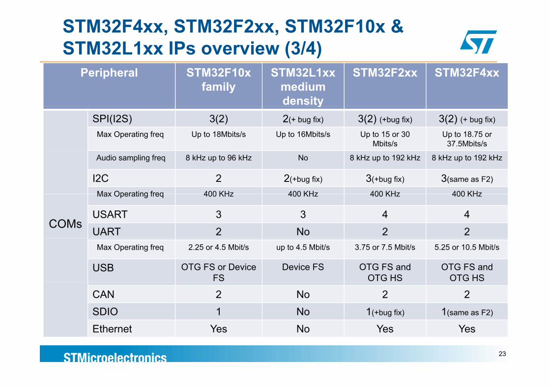
STM32F4xx, STM32F2xx, STM32F10x & STM32L1xx IPs overview (3/4)
Peripheral STM32F10x family
STM32L1xx medium density
STM32F2xx STM32F4xx
ySPI(I2S) 3(2) 2(+ bug fix) 3(2) (+bug fix) 3(2) (+ bug fix)
Max Operating freq Up to 18Mbits/s Up to 16Mbits/s Up to 15 or 30 Mbits/s
Up to 18.75 or 37.5Mbits/s
Audio sampling freq 8 kHz up to 96 kHz No 8 kHz up to 192 kHz 8 kHz up to 192 kHz
I2C 2 2(+bug fix) 3(+bug fix) 3(same as F2)
Max Operating freq 400 KHz 400 KHz 400 KHz 400 KHz
COMs
Max Operating freq 400 KHz 400 KHz 400 KHz 400 KHz
USART 3 3 4 4UART 2 No 2 2
Max Operating freq 2.25 or 4.5 Mbit/s up to 4.5 Mbit/s 3.75 or 7.5 Mbit/s 5.25 or 10.5 Mbit/s
USB OTG FS or Device FS
Device FS OTG FS and OTG HS
OTG FS and OTG HS
CAN 2 No 2 2SDIO 1 No 1(+bug fix) 1(same as F2)
Eth t Y N Y YEthernet Yes No Yes Yes
23
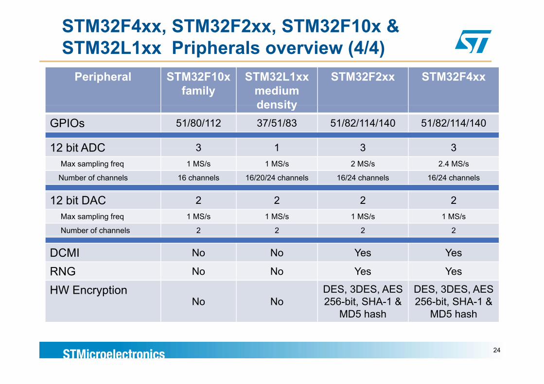
STM32F4xx, STM32F2xx, STM32F10x & STM32L1xx Pripherals overview (4/4)
Peripheral STM32F10x family
STM32L1xx medium density
STM32F2xx STM32F4xx
density GPIOs 51/80/112 37/51/83 51/82/114/140 51/82/114/140
12 bit ADC 3 1 3 312 bit ADC 3 1 3 3Max sampling freq 1 MS/s 1 MS/s 2 MS/s 2.4 MS/s
Number of channels 16 channels 16/20/24 channels 16/24 channels 16/24 channels
12 bit DAC 2 2 2 2Max sampling freq 1 MS/s 1 MS/s 1 MS/s 1 MS/s
Number of channels 2 2 2 2
DCMI No No Yes Yes
RNG No No Yes Yes
HW EncryptionNo No
DES, 3DES, AES 256-bit, SHA-1 &
MD5 hash
DES, 3DES, AES 256-bit, SHA-1 &
MD5 hash
24
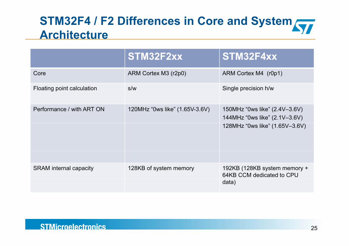
STM32F4 / F2 Differences in Core and System Architecture
STM32F2xx STM32F4xxCore ARM Cortex M3 (r2p0) ARM Cortex M4 (r0p1)
Floating point calculation s/w Single precision h/w
Performance / with ART ON 120MHz “0ws like” (1.65V-3.6V) 150MHz “0ws like” (2.4V–3.6V)144MHz “0ws like” (2.1V–3.6V)128MHz “0ws like” (1.65V–3.6V)
SRAM internal capacity 128KB of system memory 192KB (128KB system memory + 64KB CCM dedicated to CPU data)
25
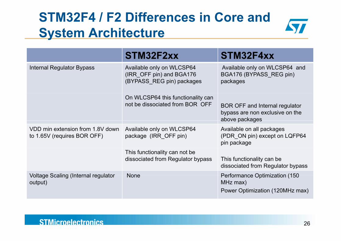
STM32F4 / F2 Differences in Core and System Architecturey
STM32F2xx STM32F4xxI t l R l t B A il bl l WLCSP64 A il bl l WLCSP64 dInternal Regulator Bypass Available only on WLCSP64
(IRR_OFF pin) and BGA176 (BYPASS_REG pin) packages
Available only on WLCSP64 and BGA176 (BYPASS_REG pin) packages
On WLCSP64 this functionality can not be dissociated from BOR OFF BOR OFF and Internal regulator
bypass are non exclusive on the above packagesabove packages
VDD min extension from 1.8V down to 1.65V (requires BOR OFF)
Available only on WLCSP64 package (IRR_OFF pin)
Available on all packages (PDR_ON pin) except on LQFP64 pin package
This functionality can not be dissociated from Regulator bypass This functionality can be
dissociated from Regulator bypass
Voltage Scaling (Internal regulator None Performance Optimization (150Voltage Scaling (Internal regulator output)
None Performance Optimization (150 MHz max)Power Optimization (120MHz max)
26
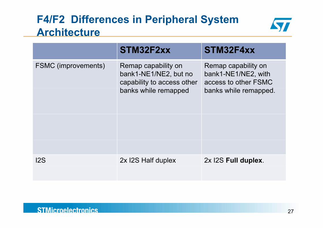
F4/F2 Differences in Peripheral System Architecture
STM32F2xx STM32F4xxFSMC (improvements) Remap capability on
bank1-NE1/NE2, but no capability to access other b k hil d
Remap capability on bank1-NE1/NE2, with access to other FSMC b k hil dbanks while remapped banks while remapped.
I2S 2x I2S Half duplex 2x I2S Full duplex.
27
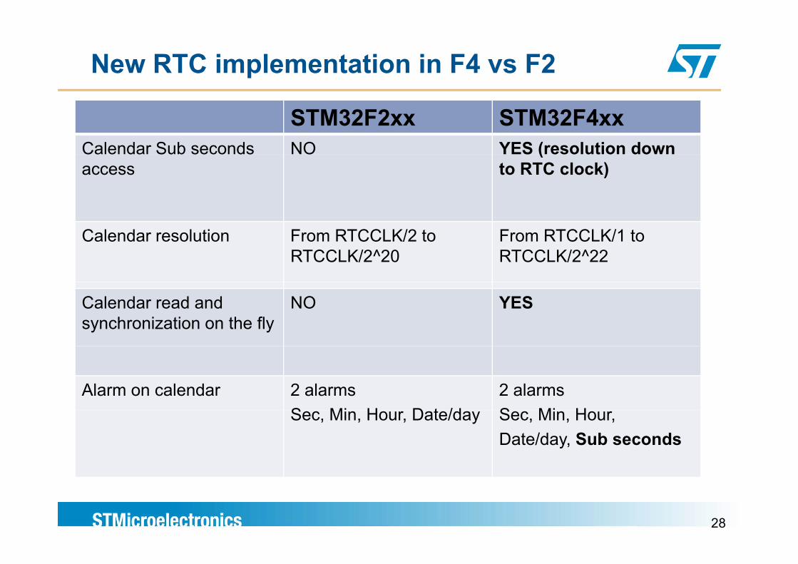
New RTC implementation in F4 vs F2
STM32F2xx STM32F4xxCalendar Sub seconds NO YES (resolution downCalendar Sub seconds access
NO YES (resolution down to RTC clock)
Calendar resolution From RTCCLK/2 to RTCCLK/2^20
From RTCCLK/1 to RTCCLK/2^22
Calendar read and synchronization on the fly
NO YES
Alarm on calendar 2 alarmsS Mi H D t /d
2 alarmsS Mi HSec, Min, Hour, Date/day Sec, Min, Hour, Date/day, Sub seconds
28
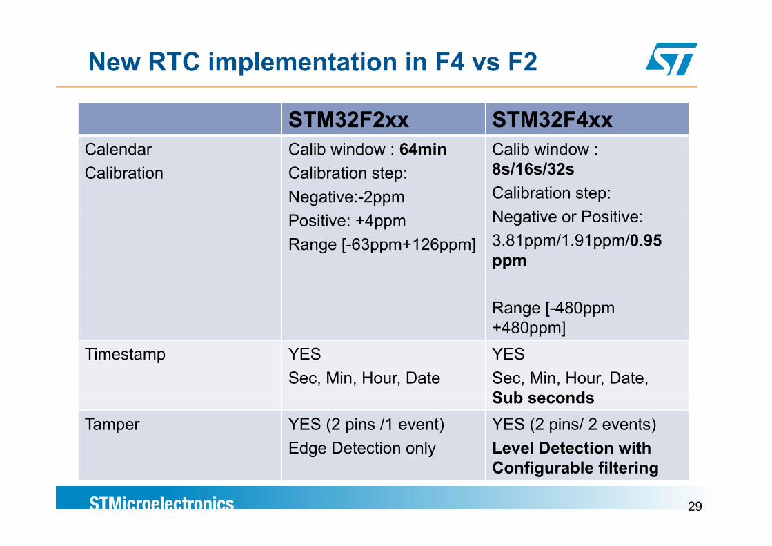
New RTC implementation in F4 vs F2
STM32F2xx STM32F4xxCalendar Calib window : 64min Calib window :Calendar Calibration
Calib window : 64min Calibration step: Negative:-2ppm
Calib window : 8s/16s/32sCalibration step: N ti P itiPositive: +4ppm
Range [-63ppm+126ppm]
Negative or Positive:3.81ppm/1.91ppm/0.95 ppm
Range [-480ppm +480ppm]pp ]
Timestamp YESSec, Min, Hour, Date
YESSec, Min, Hour, Date, Sub secondsSub seconds
Tamper YES (2 pins /1 event)Edge Detection only
YES (2 pins/ 2 events)Level Detection with
29
Configurable filtering
ARM Cortex M4ARM Cortex M4
OverviewOverview
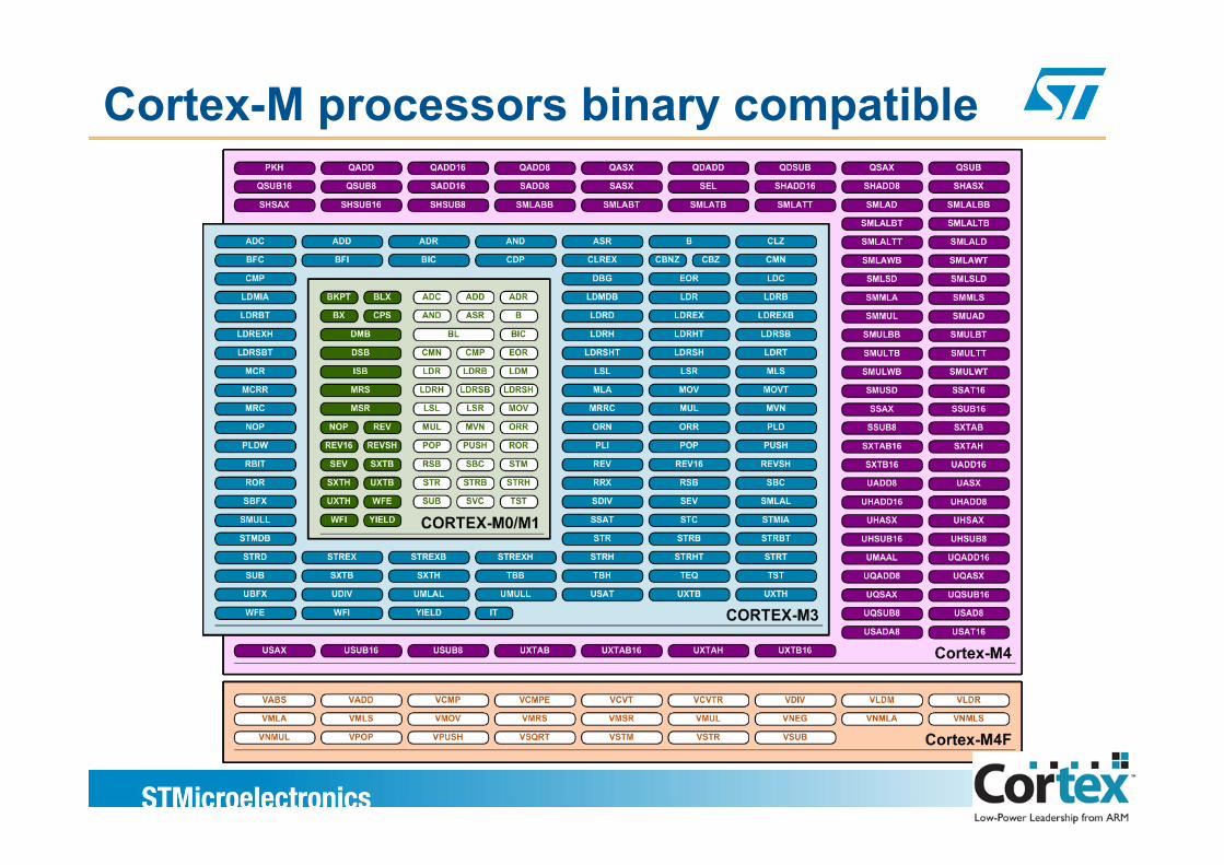
Cortex-M processors binary compatible
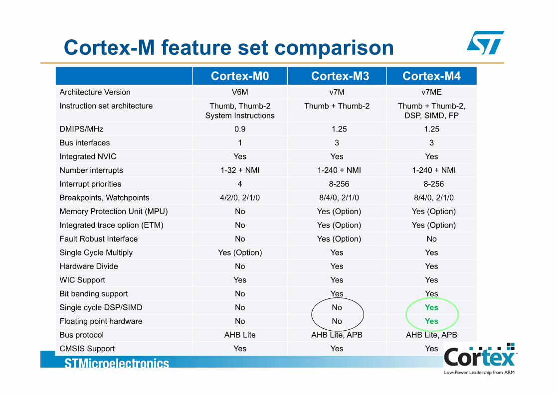
Cortex-M feature set comparisonCortex-M0 Cortex-M3 Cortex-M4
Architecture Version V6M v7M v7ME
Instruction set architecture Thumb Thumb-2 Thumb + Thumb-2 Thumb + Thumb-2Instruction set architecture Thumb, Thumb 2 System Instructions
Thumb + Thumb 2 Thumb + Thumb 2,DSP, SIMD, FP
DMIPS/MHz 0.9 1.25 1.25
Bus interfaces 1 3 3
Integrated NVIC Yes Yes Yes
Number interrupts 1-32 + NMI 1-240 + NMI 1-240 + NMI
Interrupt priorities 4 8-256 8-256
Breakpoints Watchpoints 4/2/0 2/1/0 8/4/0 2/1/0 8/4/0 2/1/0Breakpoints, Watchpoints 4/2/0, 2/1/0 8/4/0, 2/1/0 8/4/0, 2/1/0
Memory Protection Unit (MPU) No Yes (Option) Yes (Option)
Integrated trace option (ETM) No Yes (Option) Yes (Option)
Fault Robust Interface No Yes (Option) No( p )
Single Cycle Multiply Yes (Option) Yes Yes
Hardware Divide No Yes Yes
WIC Support Yes Yes Yes
Bit banding support No Yes Yes
Single cycle DSP/SIMD No No YesFloating point hardware No No Yes
32
Bus protocol AHB Lite AHB Lite, APB AHB Lite, APB
CMSIS Support Yes Yes Yes
Cortex M4Cortex M4
DSP featuresDSP features
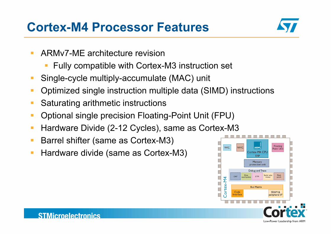
Cortex-M4 Processor Features
ARMv7-ME architecture revisionF ll tibl ith C t M3 i t ti tFully compatible with Cortex-M3 instruction set
Single-cycle multiply-accumulate (MAC) unitOptimized single instruction multiple data (SIMD) instructionsOptimized single instruction multiple data (SIMD) instructionsSaturating arithmetic instructionsOptional single precision Floating-Point Unit (FPU)Optional single precision Floating Point Unit (FPU)Hardware Divide (2-12 Cycles), same as Cortex-M3Barrel shifter (same as Cortex-M3)( )Hardware divide (same as Cortex-M3)
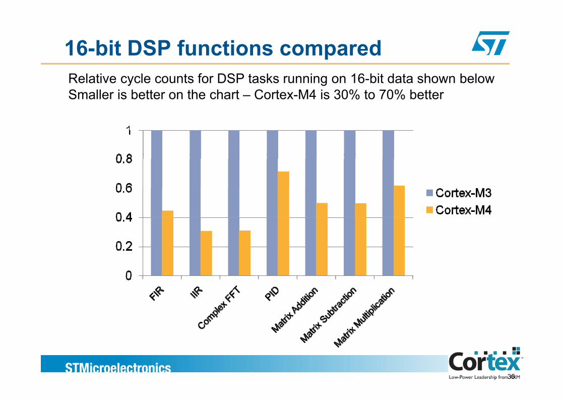
16-bit DSP functions comparedRelative cycle counts for DSP tasks running on 16-bit data shown belowSmaller is better on the chart – Cortex-M4 is 30% to 70% better
35
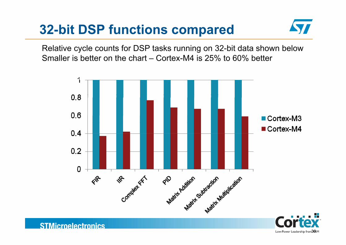
32-bit DSP functions comparedRelative cycle counts for DSP tasks running on 32-bit data shown belowSmaller is better on the chart – Cortex-M4 is 25% to 60% better
36

DSP application example:MP3 audio playback
MHz required for MP3 decode (smaller is better !)
37DSP Concept
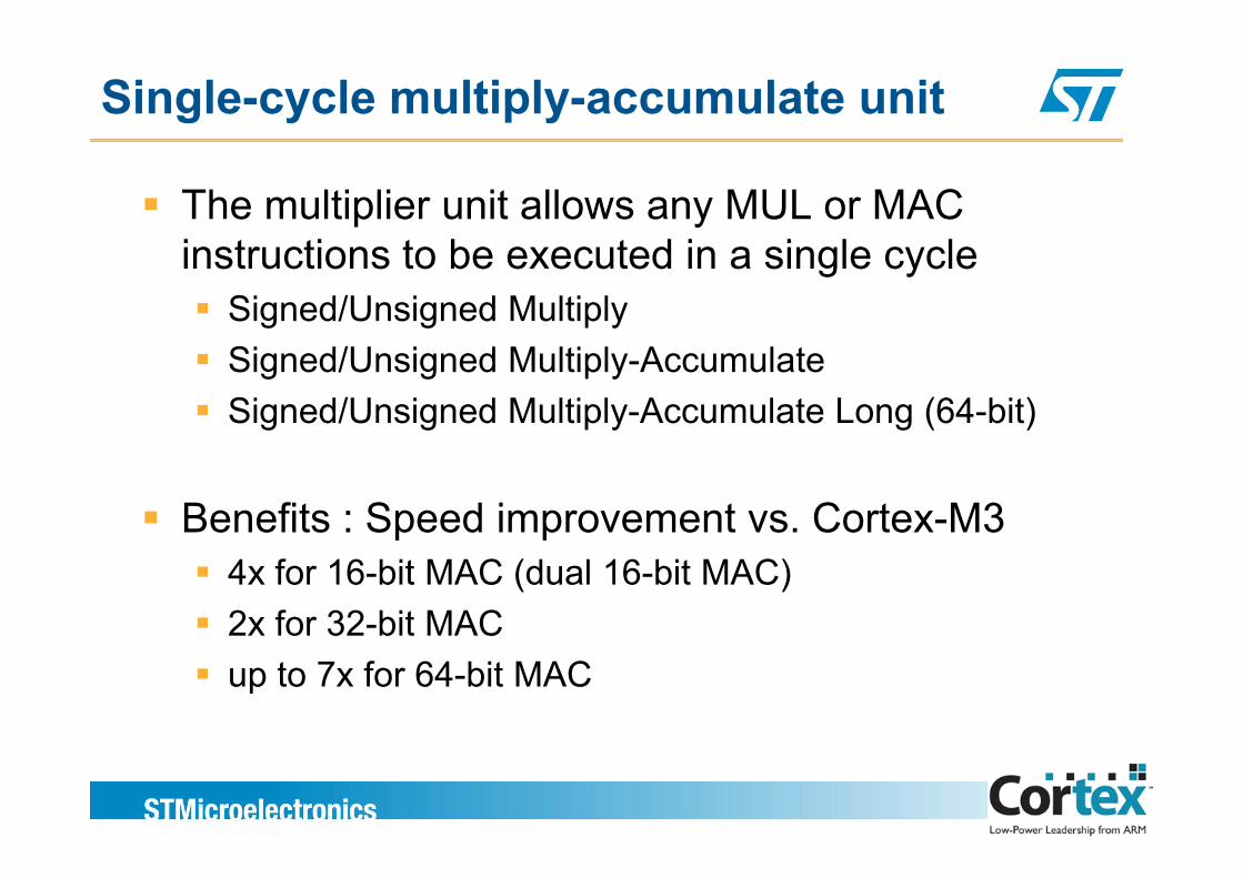
Single-cycle multiply-accumulate unit
The multiplier unit allows any MUL or MAC i t ti t b t d i i l linstructions to be executed in a single cycle
Signed/Unsigned MultiplySigned/Unsigned Multiply-AccumulateSigned/Unsigned Multiply-Accumulate Long (64-bit)
Benefits : Speed improvement vs. Cortex-M3p p4x for 16-bit MAC (dual 16-bit MAC)2x for 32-bit MACup to 7x for 64-bit MAC
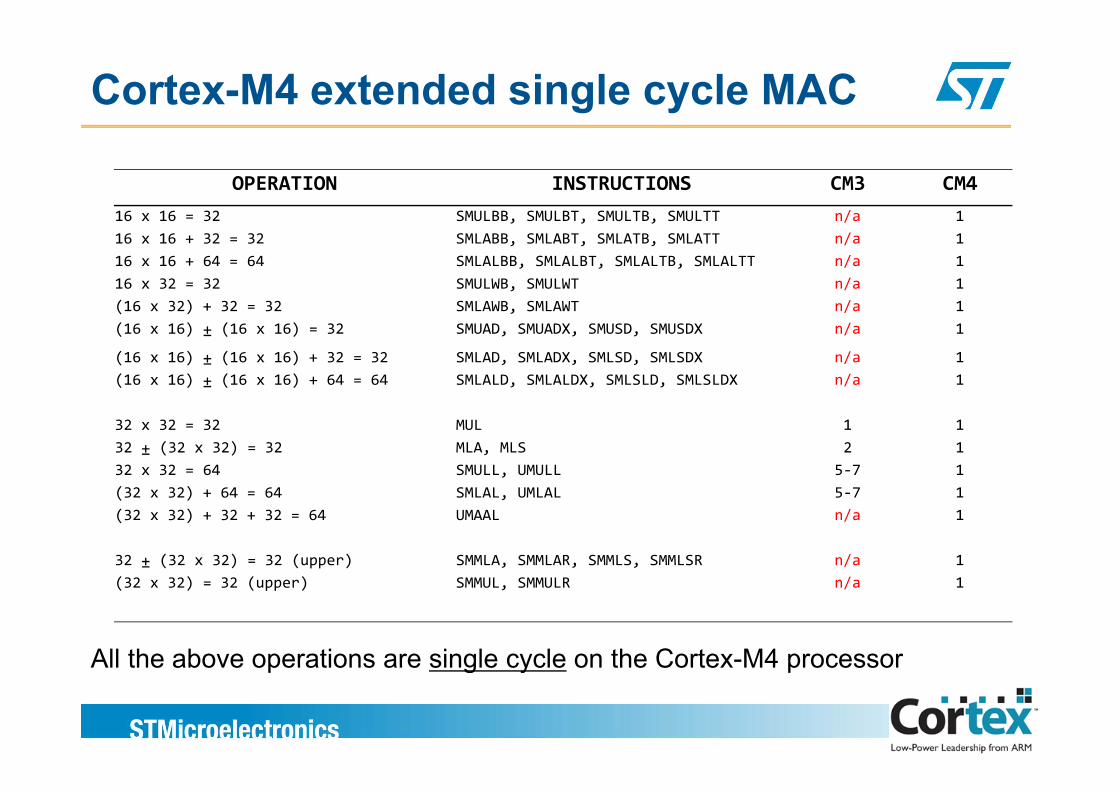
Cortex-M4 extended single cycle MAC
OPERATION INSTRUCTIONS CM3 CM416 x 16 = 32 SMULBB SMULBT SMULTB SMULTT n/a 116 x 16 = 32 SMULBB, SMULBT, SMULTB, SMULTT n/a 116 x 16 + 32 = 32 SMLABB, SMLABT, SMLATB, SMLATT n/a 116 x 16 + 64 = 64 SMLALBB, SMLALBT, SMLALTB, SMLALTT n/a 116 x 32 = 32 SMULWB, SMULWT n/a 1(16 x 32) + 32 = 32 SMLAWB SMLAWT n/a 1(16 x 32) + 32 = 32 SMLAWB, SMLAWT n/a 1(16 x 16) ± (16 x 16) = 32 SMUAD, SMUADX, SMUSD, SMUSDX n/a 1
(16 x 16) ± (16 x 16) + 32 = 32 SMLAD, SMLADX, SMLSD, SMLSDX n/a 1(16 x 16) ± (16 x 16) + 64 = 64 SMLALD, SMLALDX, SMLSLD, SMLSLDX n/a 1
32 x 32 = 32 MUL 1 132 ± (32 x 32) = 32 MLA, MLS 2 132 x 32 = 64 SMULL, UMULL 5‐7 1(32 x 32) + 64 = 64 SMLAL, UMLAL 5‐7 1(32 x 32) + 32 + 32 = 64 UMAAL n/a 1
32 ± (32 x 32) = 32 (upper) SMMLA, SMMLAR, SMMLS, SMMLSR n/a 1(32 x 32) = 32 (upper) SMMUL, SMMULR n/a 1
All the above operations are single cycle on the Cortex-M4 processorAll the above operations are single cycle on the Cortex M4 processor
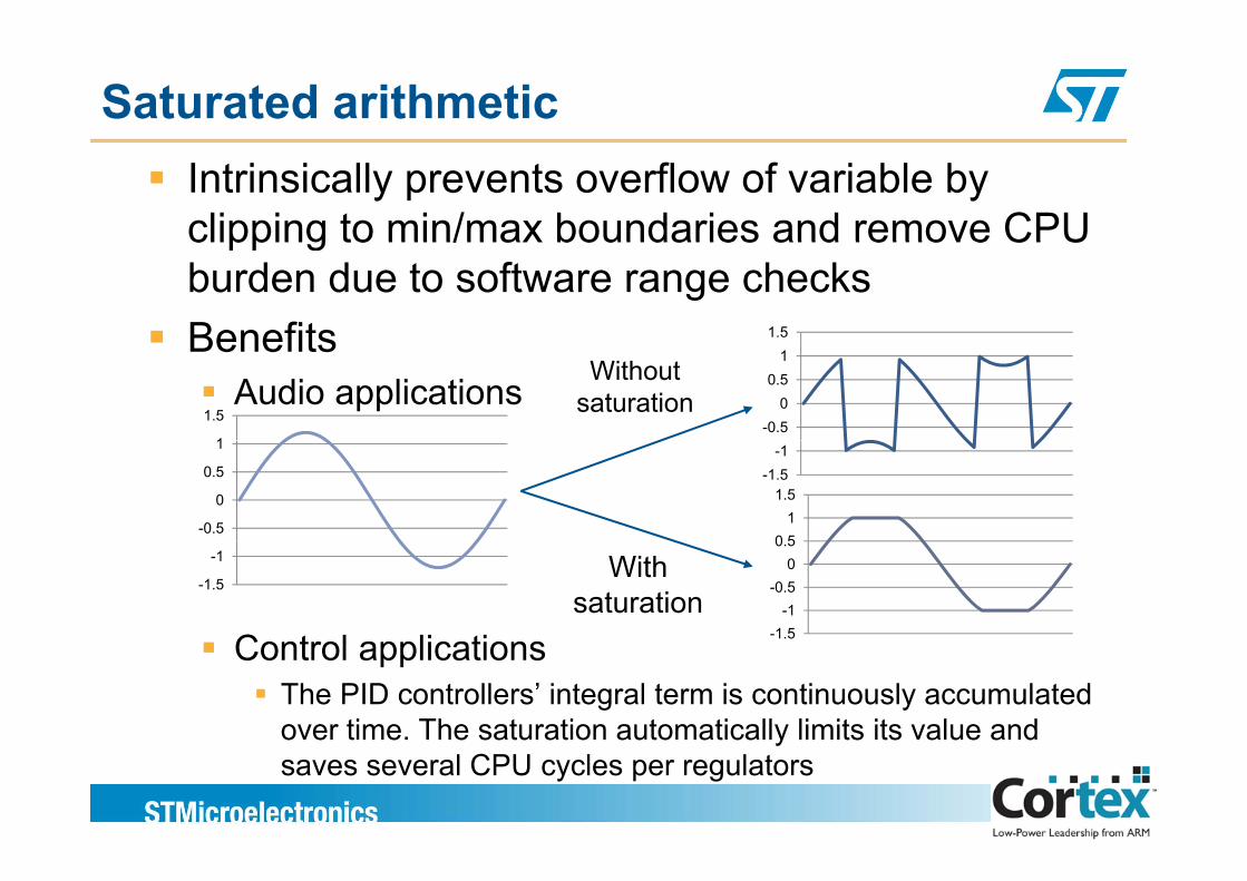
Saturated arithmeticIntrinsically prevents overflow of variable by clipping to min/max boundaries and remove CPUclipping to min/max boundaries and remove CPU burden due to software range checksBenefits 1.5Benefits
Audio applications1
1.5-0.5
00.5
1Without
saturation
0 51
1.5
-0.5
0
0.5
1
-1.5-1
C t l li ti -1.5-1
-0.50
0.5
-1.5
-1 Withsaturation
Control applicationsThe PID controllers’ integral term is continuously accumulated over time. The saturation automatically limits its value and ysaves several CPU cycles per regulators
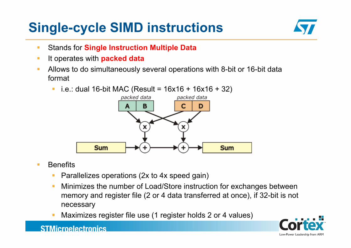
Single-cycle SIMD instructionsStands for Single Instruction Multiple DataIt operates with packed dataAllo s to do sim ltaneo sl se eral operations ith 8 bit or 16 bit dataAllows to do simultaneously several operations with 8-bit or 16-bit data format
i.e.: dual 16-bit MAC (Result = 16x16 + 16x16 + 32)
BenefitsParallelizes operations (2x to 4x speed gain)Minimizes the number of Load/Store instruction for exchanges between memory and register file (2 or 4 data transferred at once), if 32-bit is not necessaryMaximizes register file use (1 register holds 2 or 4 values)
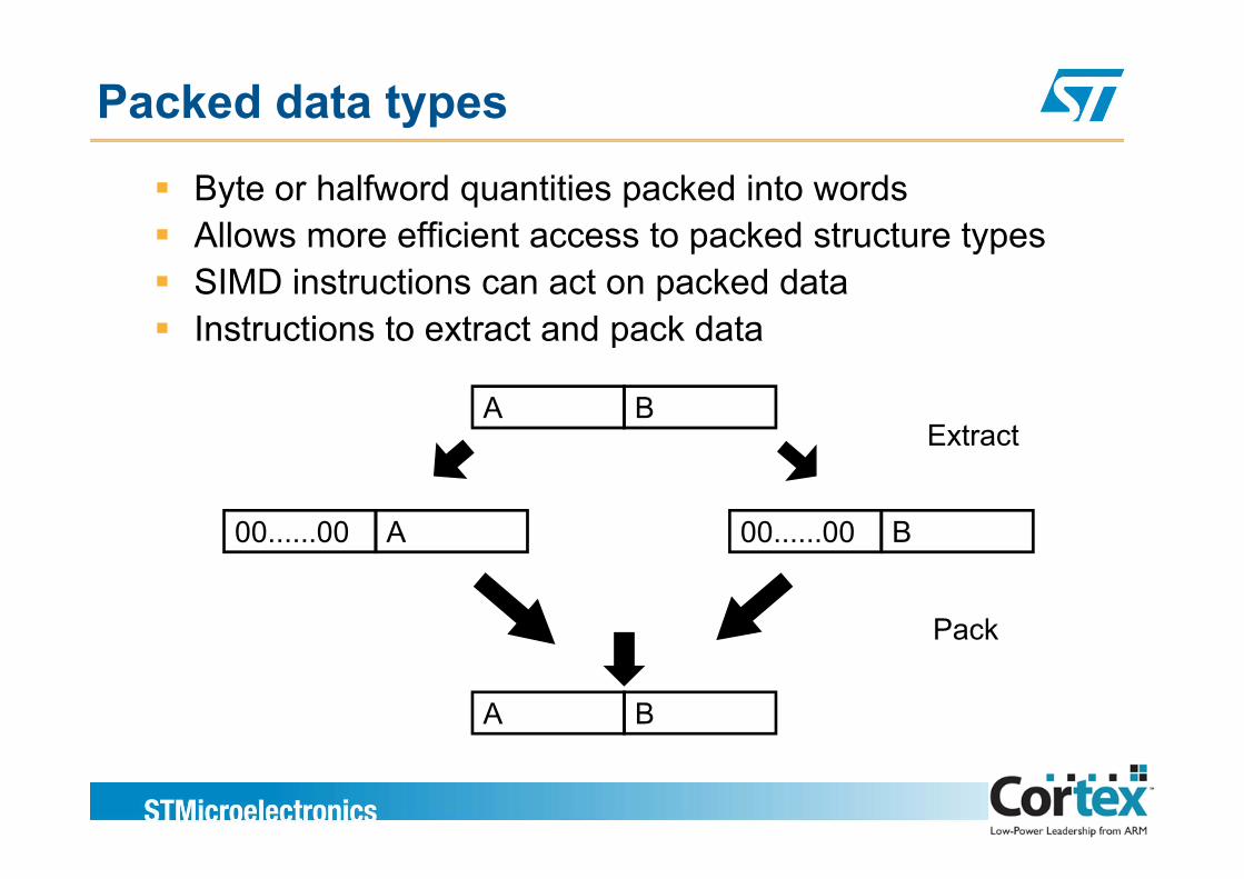
Packed data types
Byte or halfword quantities packed into wordsAllows more efficient access to packed structure typesAllows more efficient access to packed structure typesSIMD instructions can act on packed dataInstructions to extract and pack dataInstructions to extract and pack data
A BExtract
B00......00A00......00
Extract
B00......00A00......00
Pack
A B
Pack

DSP lib provided for free by ARM
The benefits of software libraries for Cortex-M4Enables end user to develop applications fasterEnables end user to develop applications faster
Keeps end user abstracted from low level programmingBenchmarking vehicle during system developmentClear competitive positioning against incumbent DSP/DSC offeringsClear competitive positioning against incumbent DSP/DSC offeringsAccelerate third party software development
Keeping it easy to access for end userMinimal entry barrier - very easy to access and use
One standard library – no duplicated effortsARM channels effort/resources with software partnerValue add through another level of software – eg: filter config tools
43
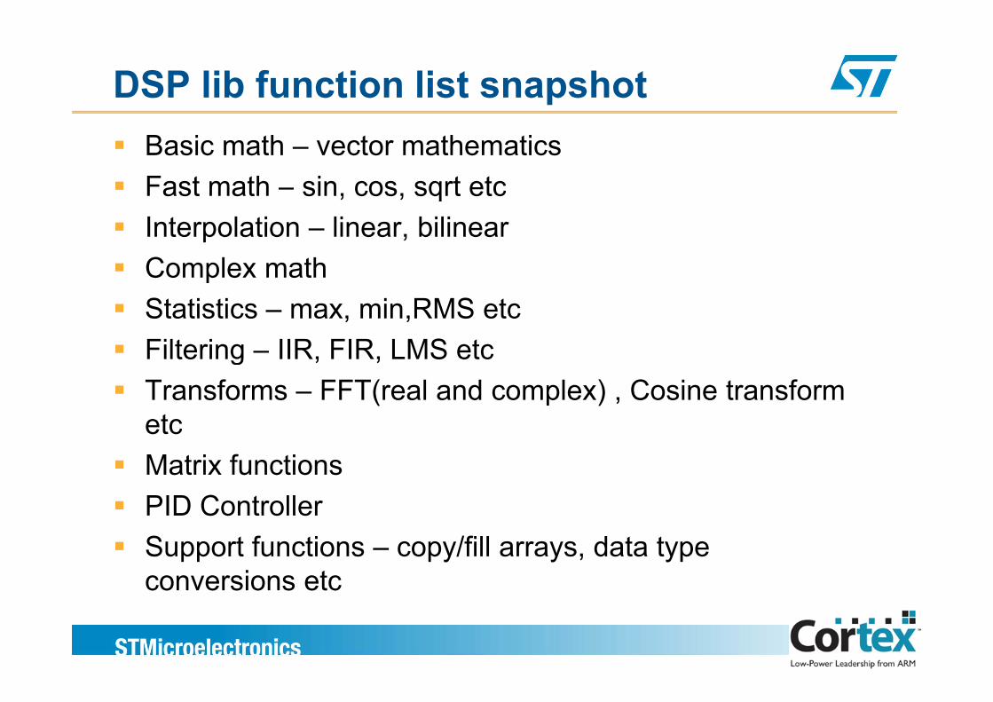
DSP lib function list snapshotBasic math – vector mathematicsFast math – sin cos sqrt etcFast math sin, cos, sqrt etcInterpolation – linear, bilinearComplex mathComplex mathStatistics – max, min,RMS etcFiltering – IIR FIR LMS etcFiltering – IIR, FIR, LMS etcTransforms – FFT(real and complex) , Cosine transform etcetcMatrix functionsPID ControllerPID ControllerSupport functions – copy/fill arrays, data type conversions etc
44
conversions etc
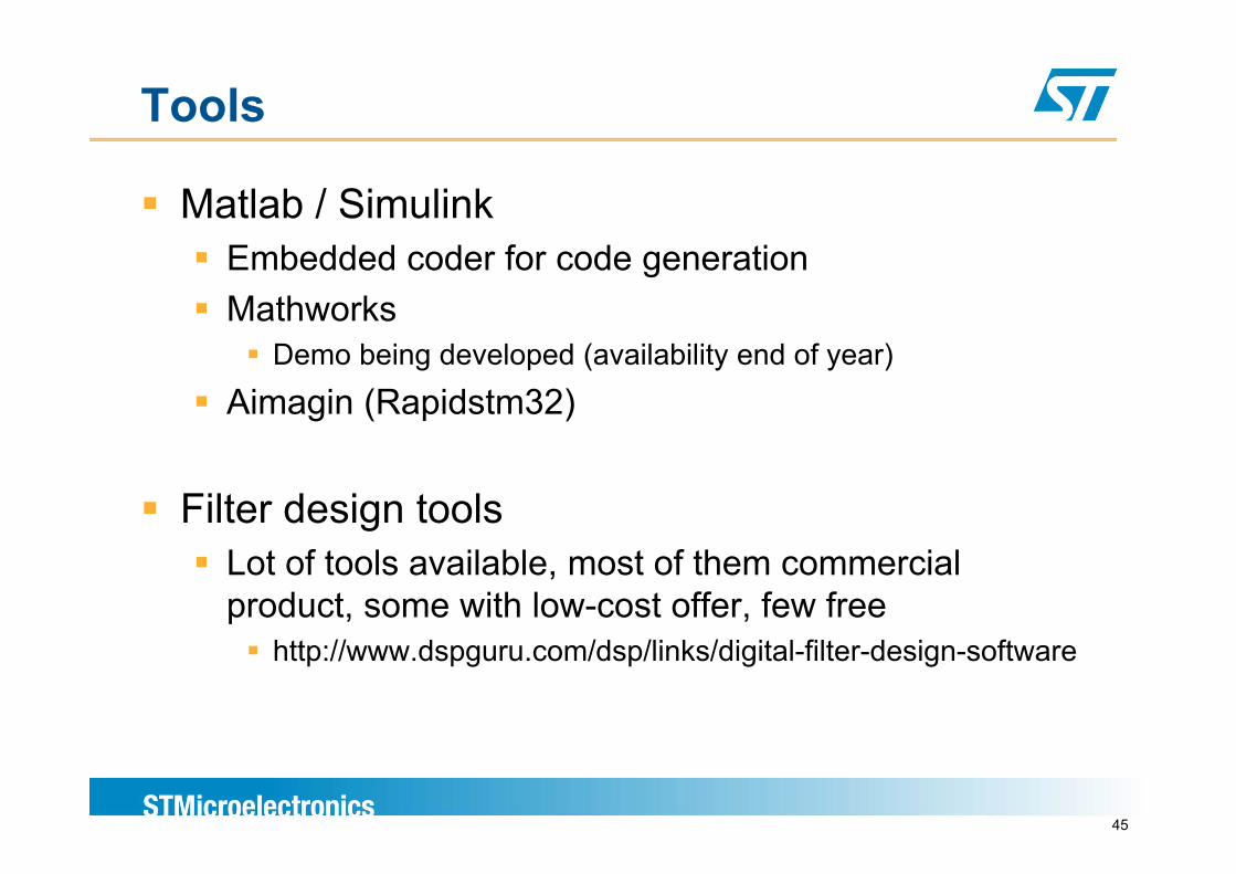
Tools
Matlab / SimulinkEmbedded coder for code generationMathworks
Demo being developed (availability end of year)
Aimagin (Rapidstm32)
Filter design toolsLot of tools available, most of them commercial product, some with low-cost offer, few free
http://www.dspguru.com/dsp/links/digital-filter-design-software
45
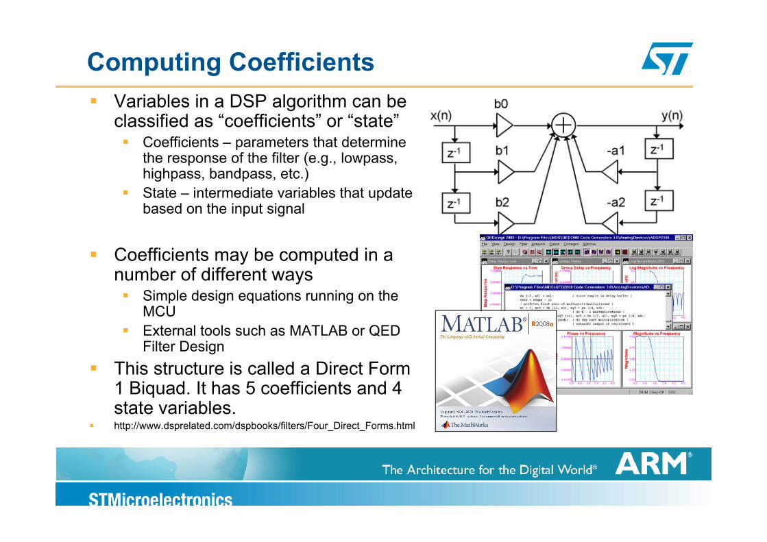
Computing CoefficientsVariables in a DSP algorithm can be classified as “coefficients” or “state”
Coefficients – parameters that determine pthe response of the filter (e.g., lowpass, highpass, bandpass, etc.)State – intermediate variables that update based on the input signalbased on the input signal
Coefficients may be computed in a number of different waysnumber of different ways
Simple design equations running on the MCUExternal tools such as MATLAB or QEDExternal tools such as MATLAB or QED Filter Design
This structure is called a Direct Form 1 Biquad. It has 5 coefficients and 41 Biquad. It has 5 coefficients and 4 state variables.http://www.dsprelated.com/dspbooks/filters/Four_Direct_Forms.html
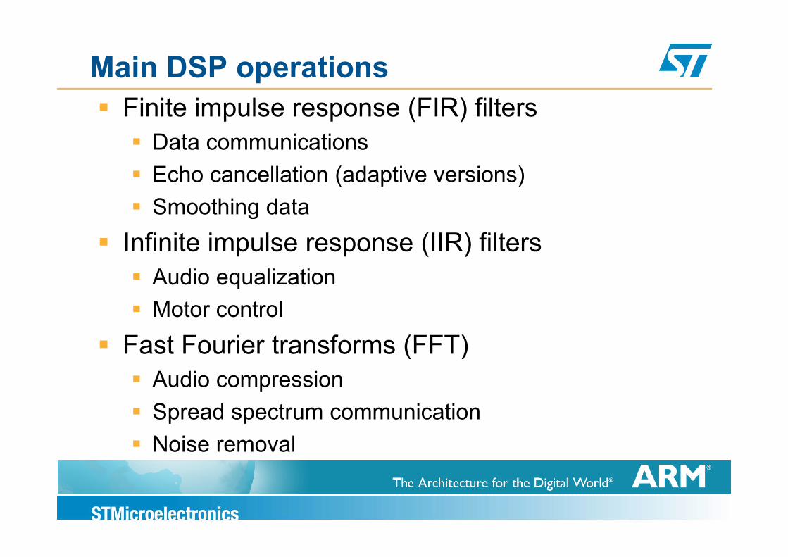
Main DSP operationsFinite impulse response (FIR) filters
Data communicationsEcho cancellation (adaptive versions)Smoothing datag
Infinite impulse response (IIR) filtersAudio equalizationAudio equalizationMotor control
Fast Fourier transforms (FFT)Fast Fourier transforms (FFT)Audio compressionS d t i tiSpread spectrum communicationNoise removal
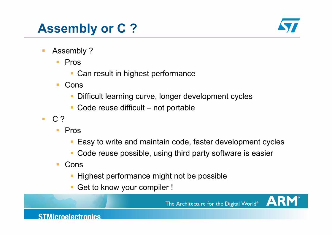
Assembly or C ?Assembly ?
ProsProsCan result in highest performance
ConsDifficult learning curve, longer development cyclesCode reuse difficult – not portable
C ?C ?Pros
Easy to write and maintain code, faster development cyclesEasy to write and maintain code, faster development cyclesCode reuse possible, using third party software is easier
ConsHighest performance might not be possible Get to know your compiler !
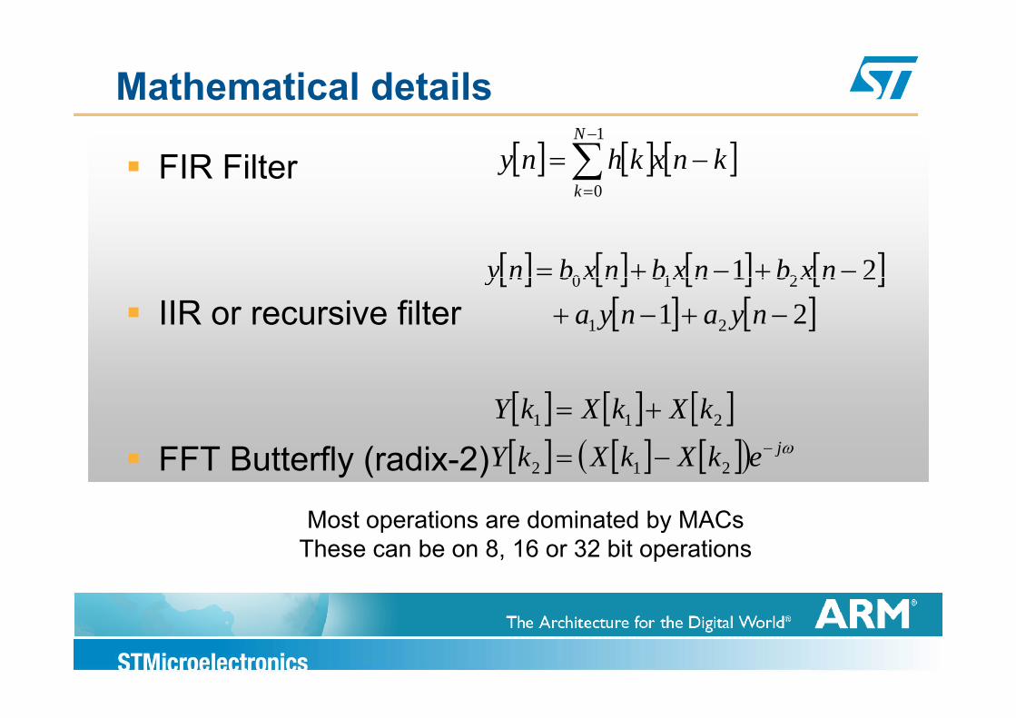
Mathematical details
FIR Filter [ ] [ ] [ ]knxkhnyN
k−=∑
−
=
1
0k 0
[ ] [ ] [ ] [ ]21 210 −+−+= nxbnxbnxbnyIIR or recursive filter
[ ] [ ] [ ] [ ][ ] [ ]21
21
21
210
−+−+++nyanya
nxbnxbnxbny
[ ] [ ] [ ][ ] [ ] [ ]( )
kXkXkY += 211
FFT Butterfly (radix-2) [ ] [ ] [ ]( ) ωjekXkXkY −−= 212
Most operations are dominated by MACsMost operations are dominated by MACsThese can be on 8, 16 or 32 bit operations
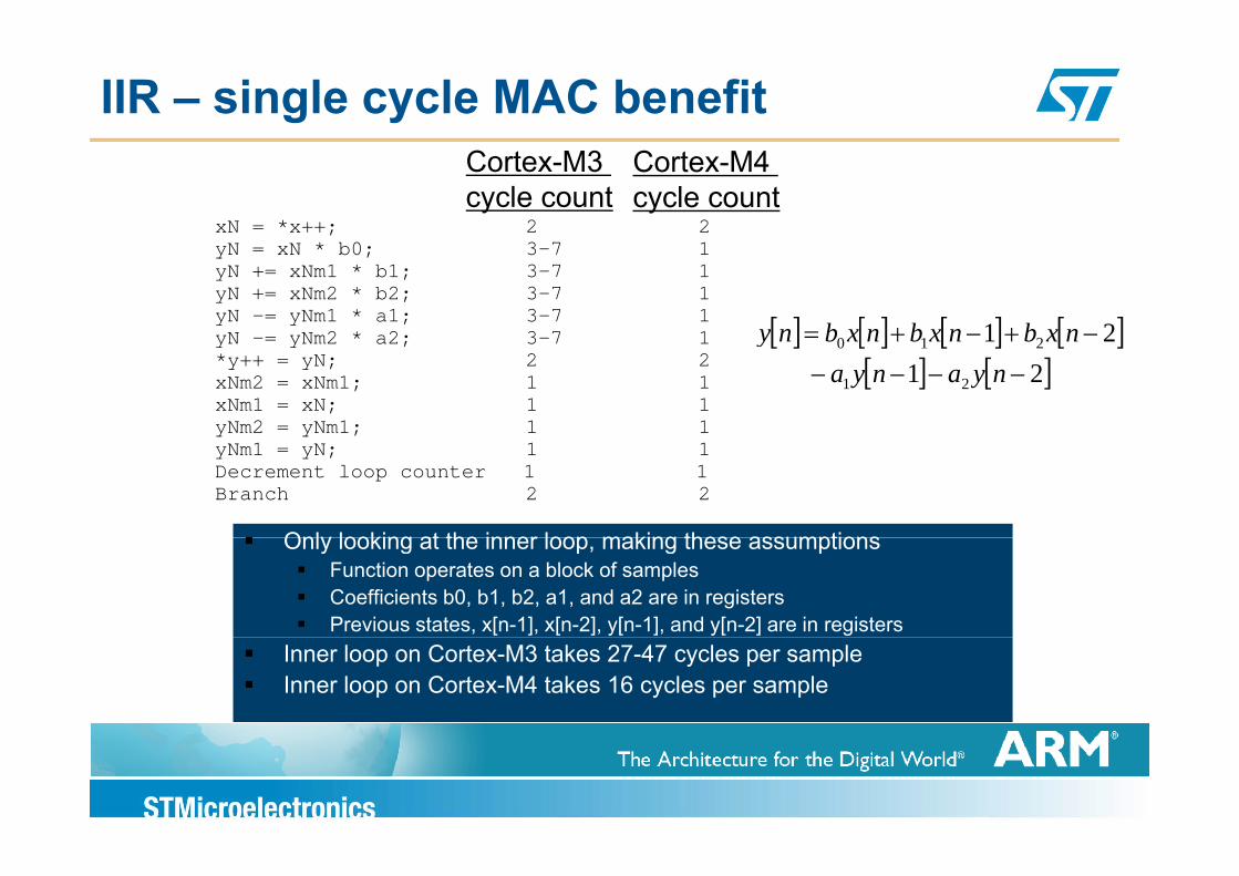
IIR – single cycle MAC benefit
xN = *x++; 2 2
Cortex-M3 cycle count
Cortex-M4 cycle count
yN = xN * b0; 3-7 1yN += xNm1 * b1; 3-7 1yN += xNm2 * b2; 3-7 1yN -= yNm1 * a1; 3-7 1yN -= yNm2 * a2; 3-7 1 [ ] [ ] [ ] [ ]21 210 −+−+= nxbnxbnxbnyyN = yNm2 a2; 3 7 1*y++ = yN; 2 2xNm2 = xNm1; 1 1xNm1 = xN; 1 1yNm2 = yNm1; 1 1
[ ] [ ] [ ] [ ][ ] [ ]21
21
21
210
−−−−++
nyanyanxbnxbnxbny
Only looking at the inner loop making these assumptions
yNm1 = yN; 1 1Decrement loop counter 1 1Branch 2 2
Only looking at the inner loop, making these assumptionsFunction operates on a block of samplesCoefficients b0, b1, b2, a1, and a2 are in registersPrevious states, x[n-1], x[n-2], y[n-1], and y[n-2] are in registers
Inner loop on Cortex-M3 takes 27-47 cycles per sampleInner loop on Cortex-M4 takes 16 cycles per sample
Further optimization strategiesCircular addressing alternatives
Loop unrolling
Caching of intermediate variables
Extensive use of SIMD and intrinsicsExtensive use of SIMD and intrinsicsThese will be illustrated by looking at a Finite Impulse Response (FIR) Filterp p ( )
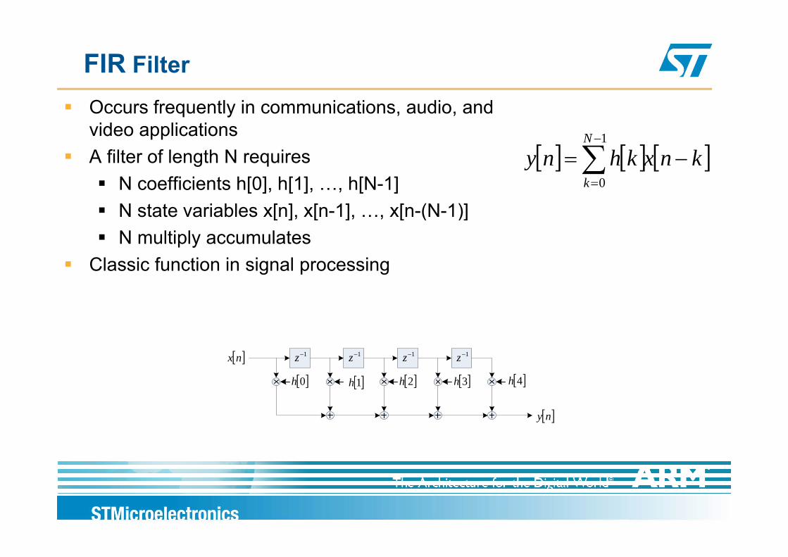
FIR Filter
Occurs frequently in communications, audio, and video applicationsA filt f l th N i [ ] [ ] [ ]kkh
N
∑−1
A filter of length N requiresN coefficients h[0], h[1], …, h[N-1]N state variables x[n], x[n-1], …, x[n-(N-1)]
[ ] [ ] [ ]knxkhnyk
−=∑=0
N state variables x[n], x[n 1], …, x[n (N 1)]N multiply accumulates
Classic function in signal processing
1−z 1−z 1−z 1−z
[ ]0h [ ]1h [ ]2h [ ]3h [ ]4h
[ ]nx
[ ]ny
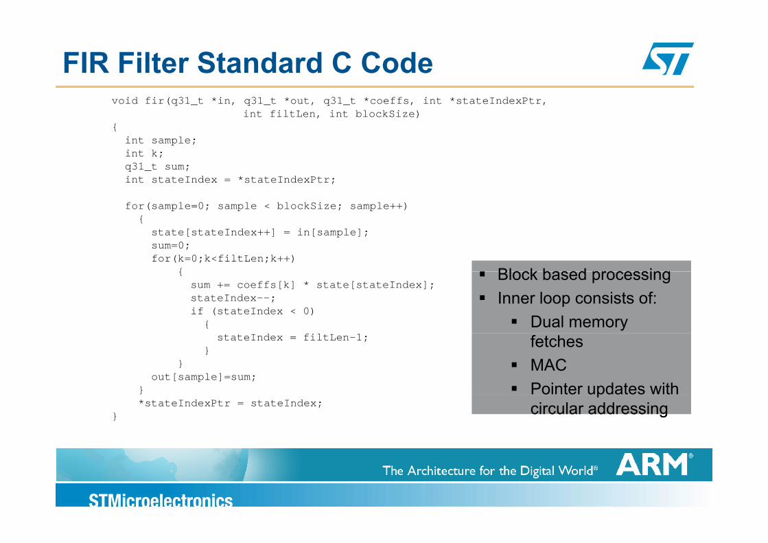
FIR Filter Standard C Codevoid fir(q31_t *in, q31_t *out, q31_t *coeffs, int *stateIndexPtr,
int filtLen, int blockSize){
int sample;int k;q31_t sum;int stateIndex = *stateIndexPtr;
for(sample=0; sample < blockSize; sample++)
Block based processingBlock based processing
( p ; p ; p ){
state[stateIndex++] = in[sample];sum=0;for(k=0;k<filtLen;k++)
{ Block based processingInner loop consists of:
Dual memory
Block based processingInner loop consists of:
Dual memory
{sum += coeffs[k] * state[stateIndex];stateIndex--;if (stateIndex < 0)
{
fetchesMACPointer updates with
fetchesMACPointer updates with
stateIndex = filtLen-1;}
}out[sample]=sum;
} pcircular addressing
pcircular addressing*stateIndexPtr = stateIndex;
}
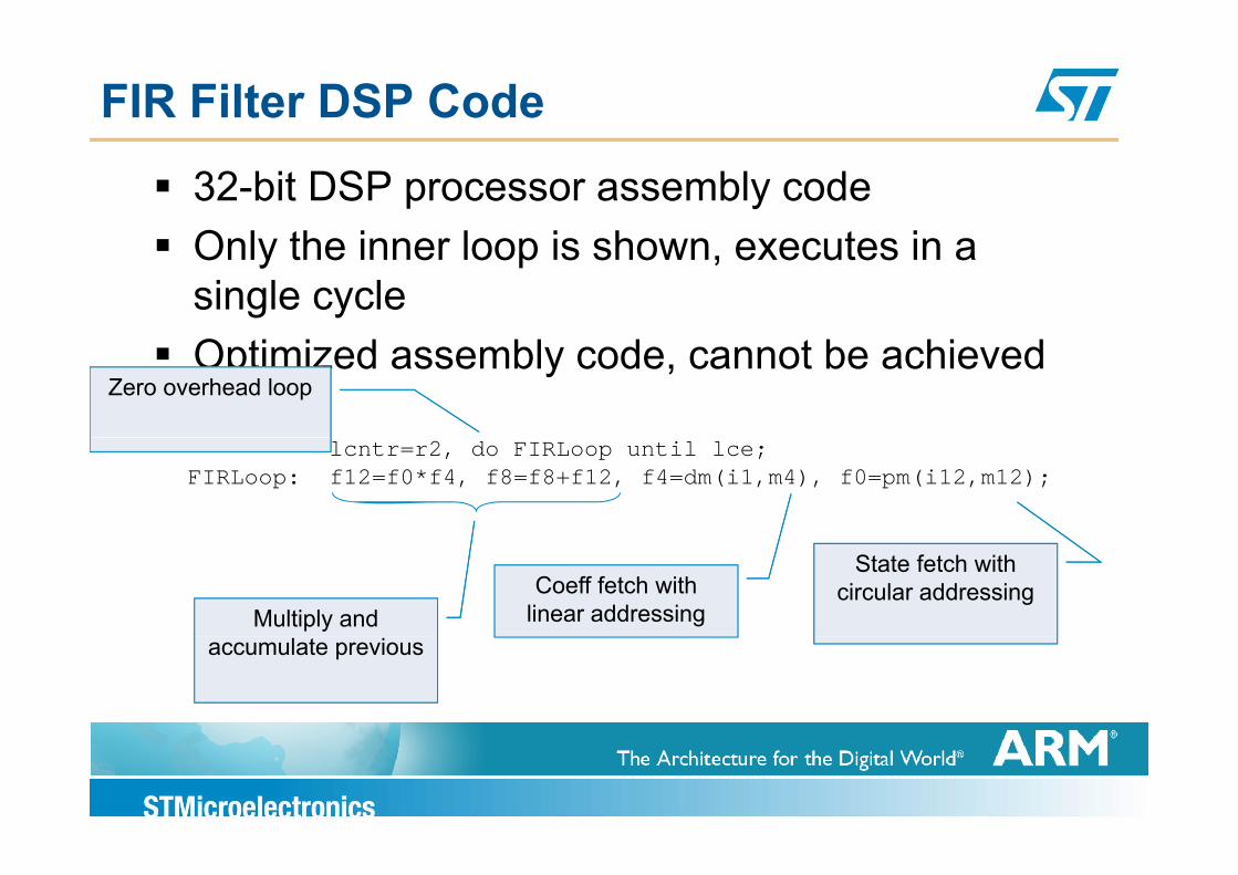
FIR Filter DSP Code
32-bit DSP processor assembly codeOnly the inner loop is shown executes in aOnly the inner loop is shown, executes in a single cycleOptimized assembly code, cannot be achieved in CZero overhead loop
lcntr=r2, do FIRLoop until lce;FIRLoop: f12=f0*f4, f8=f8+f12, f4=dm(i1,m4), f0=pm(i12,m12);
State fetch with circular addressingCoeff fetch with
linear addressingMultiply and accumulate previous
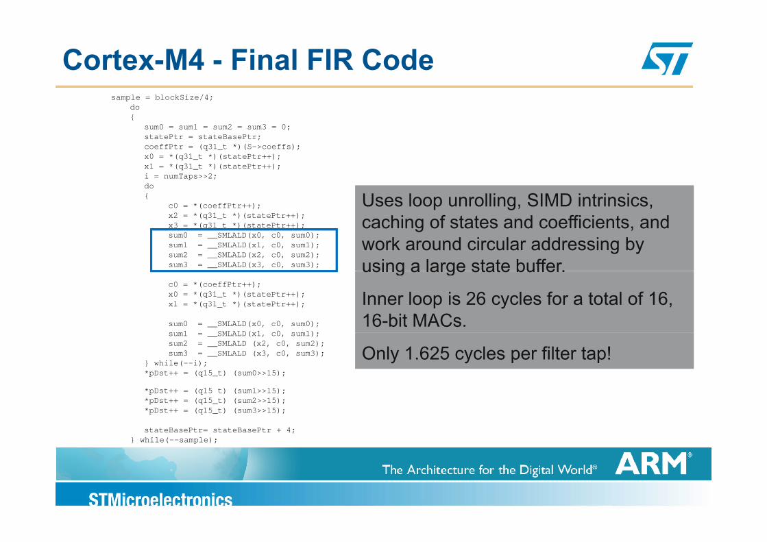
Cortex-M4 - Final FIR Codesample = blockSize/4;
do{
sum0 = sum1 = sum2 = sum3 = 0;statePtr = stateBasePtr;coeffPtr = (q31 t *)(S->coeffs);coeffPtr (q31_t )(S >coeffs);x0 = *(q31_t *)(statePtr++);x1 = *(q31_t *)(statePtr++);i = numTaps>>2;do{
c0 = *(coeffPtr++); Uses loop unrolling, SIMD intrinsics, Uses loop unrolling, SIMD intrinsics, x2 = *(q31_t *)(statePtr++);x3 = *(q31_t *)(statePtr++);sum0 = __SMLALD(x0, c0, sum0);sum1 = __SMLALD(x1, c0, sum1);sum2 = __SMLALD(x2, c0, sum2);sum3 = __SMLALD(x3, c0, sum3);
p gcaching of states and coefficients, and work around circular addressing by using a large state buffer.
p gcaching of states and coefficients, and work around circular addressing by using a large state buffer.
c0 = *(coeffPtr++);x0 = *(q31_t *)(statePtr++);x1 = *(q31_t *)(statePtr++);
sum0 = __SMLALD(x0, c0, sum0);sum1 SMLALD(x1 c0 sum1);
using a large state buffer.
Inner loop is 26 cycles for a total of 16, 16-bit MACs.
using a large state buffer.
Inner loop is 26 cycles for a total of 16, 16-bit MACs.
sum1 = __SMLALD(x1, c0, sum1);sum2 = __SMLALD (x2, c0, sum2);sum3 = __SMLALD (x3, c0, sum3);
} while(--i);*pDst++ = (q15_t) (sum0>>15);
*pDst++ = (q15 t) (sum1>>15);
Only 1.625 cycles per filter tap!Only 1.625 cycles per filter tap!
p q _*pDst++ = (q15_t) (sum2>>15);*pDst++ = (q15_t) (sum3>>15);
stateBasePtr= stateBasePtr + 4;} while(--sample);
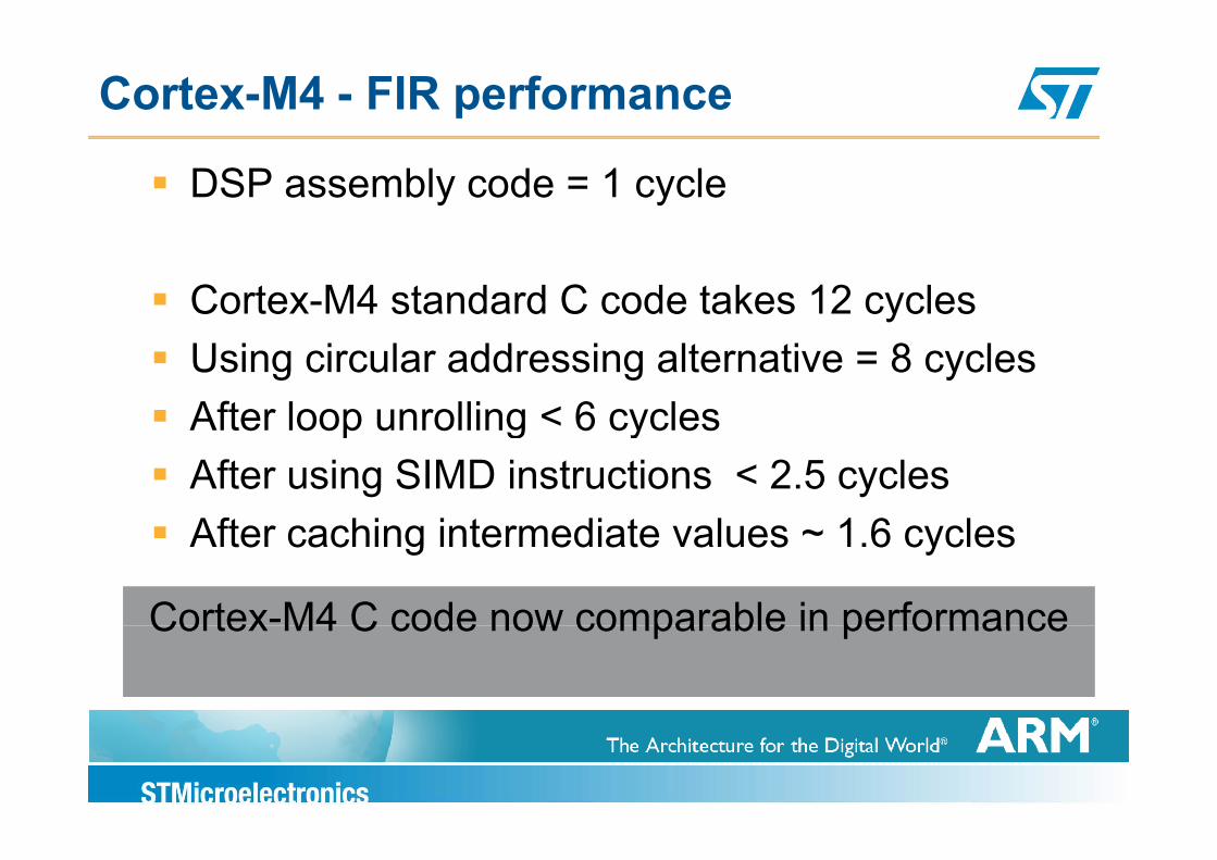
Cortex-M4 - FIR performance
DSP assembly code = 1 cycle
Cortex-M4 standard C code takes 12 cyclesUsing circular addressing alternative = 8 cyclesAfter loop unrolling < 6 cyclesAfter loop unrolling 6 cyclesAfter using SIMD instructions < 2.5 cyclesAfter caching intermediate values 1 6 cyclesAfter caching intermediate values ~ 1.6 cycles
Cortex-M4 C code now comparable in performanceCortex M4 C code now comparable in performance
Cortex M4Floating Point Unit
Cortex M4Floating Point Unit
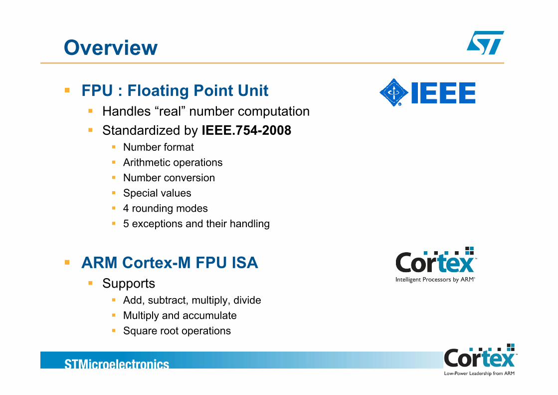
Overview
FPU : Floating Point UnitH dl “ l” b t tiHandles “real” number computationStandardized by IEEE.754-2008
Number formatArithmetic operationsNumber conversionSpecial valuesp4 rounding modes5 exceptions and their handling
ARM Cortex-M FPU ISASupportsSupports
Add, subtract, multiply, divideMultiply and accumulate Square root operationsSquare root operations
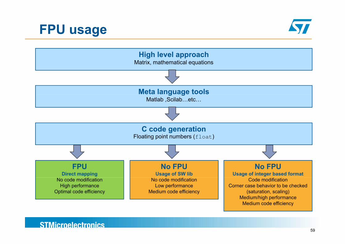
FPU usage
High level approachMatrix, mathematical equations
Meta language toolsg gMatlab ,Scilab…etc…
C code generationFloating point numbers (float)
FPUDirect mapping
No FPUUsage of SW lib
No FPUUsage of integer based format
No code modificationHigh performance
Optimal code efficiency
No code modificationLow performance
Medium code efficiency
Code modificationCorner case behavior to be checked
(saturation, scaling)Medium/high performance
Medium code efficiency
59
y
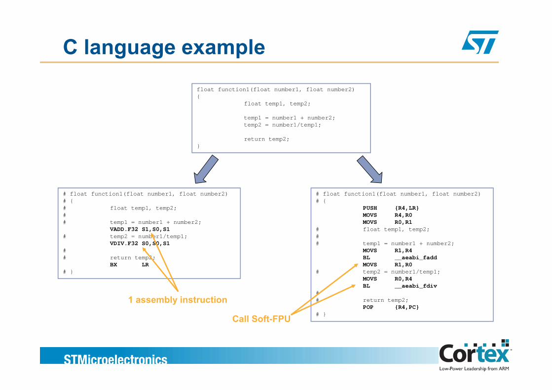
C language example
float function1(float number1, float number2){
float temp1, temp2;
temp1 = number1 + number2;temp2 = number1/temp1;
return temp2;}
# float function1(float number1, float number2) # float function1(float number1, float number2)# float function1(float number1, float number2)# {# float temp1, temp2;# # temp1 = number1 + number2;
VADD.F32 S1,S0,S1# temp2 = number1/temp1;
# float function1(float number1, float number2)# {
PUSH {R4,LR}MOVS R4,R0MOVS R0,R1
# float temp1, temp2;#
VDIV.F32 S0,S0,S1## return temp2;
BX LR# }
# temp1 = number1 + number2;MOVS R1,R4BL __aeabi_faddMOVS R1,R0
# temp2 = number1/temp1;MOVS R0,R4BL __aeabi_fdiv
## return temp2;
POP {R4,PC}# }Call Soft-FPU
1 assembly instruction
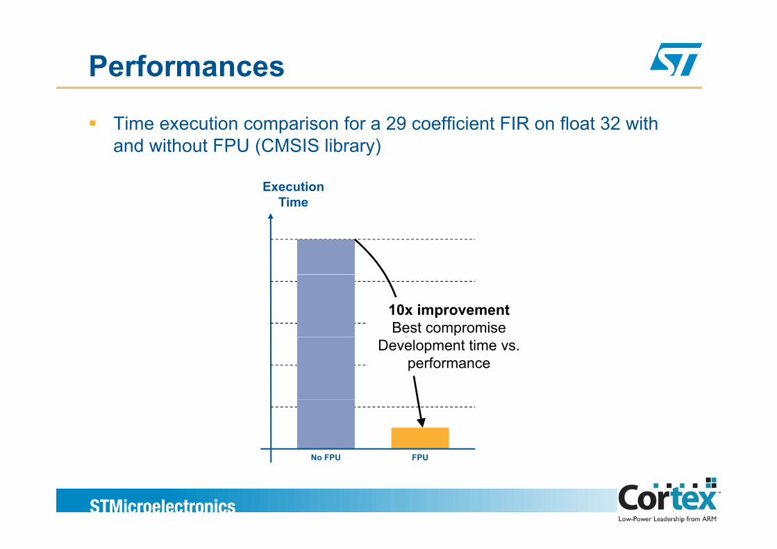
Performances
Time execution comparison for a 29 coefficient FIR on float 32 with and without FPU (CMSIS library)
ExecutionTime
and without FPU (CMSIS library)
10x improvementBest compromise
Development time vs. performance
FPUNo FPU
Rounding issues
The precision has some limitsRounding errors can be accumulated along the various operations anRounding errors can be accumulated along the various operations an may provide unaccurate results (do not do financial operations withfloatings…)
Few examplesIf you are working on two numbers in different base, the hardware
t ti ll d li f th t b t k thautomatically « denormalize » on of the two number to make the calculation in the same baseIf you are substracting two numbers very closed you are loosing the relative precision (also called cancellation error)
If you are « reorganizing » the various operations, you may not y g g p , y yobtain the same result as because of the rounding errors…
IEEE 754IEEE 754
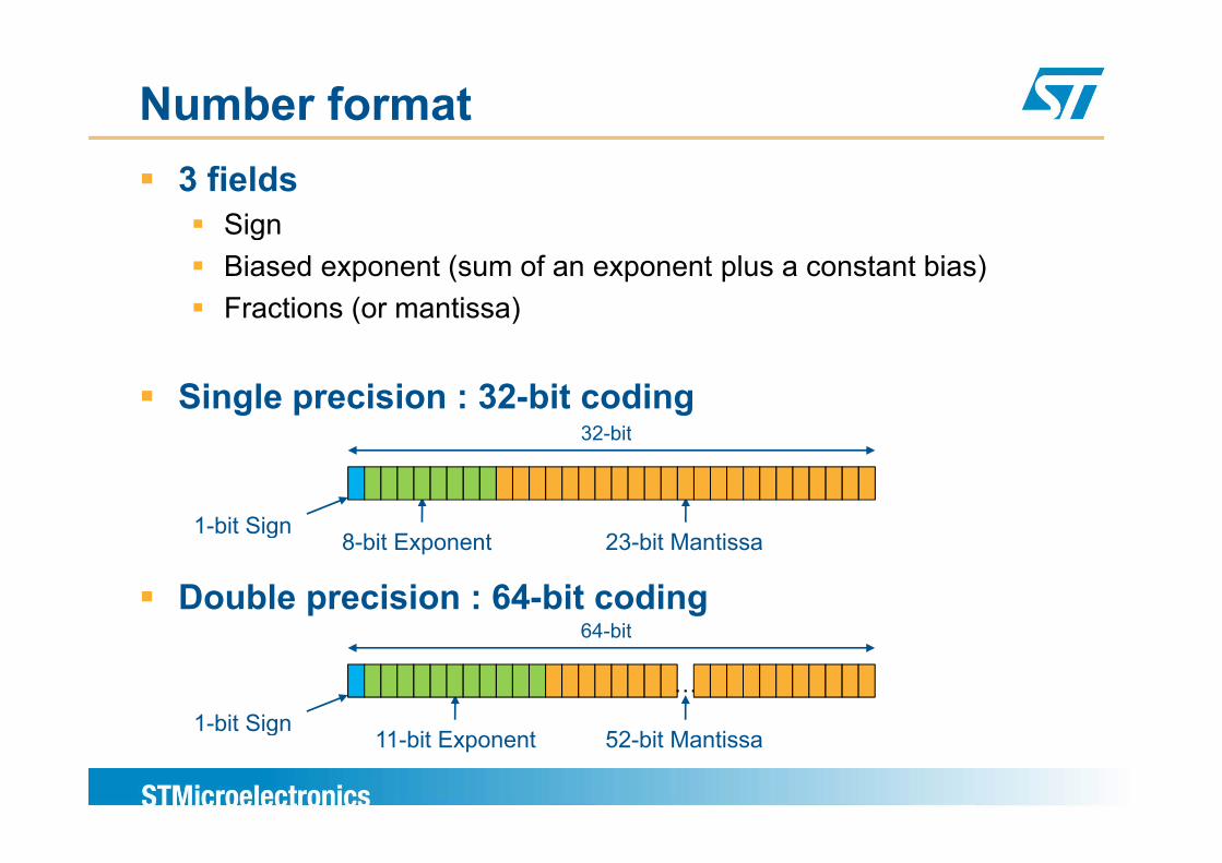
Number format3 fields
SigngBiased exponent (sum of an exponent plus a constant bias)Fractions (or mantissa)
Single precision : 32-bit coding32 bit
1-bit Sign
32-bit
Double precision : 64-bit coding
1 bit Sign8-bit Exponent 23-bit Mantissa
64 bit
1-bit Sign
…
64-bit
1-bit Sign11-bit Exponent 52-bit Mantissa
Number format
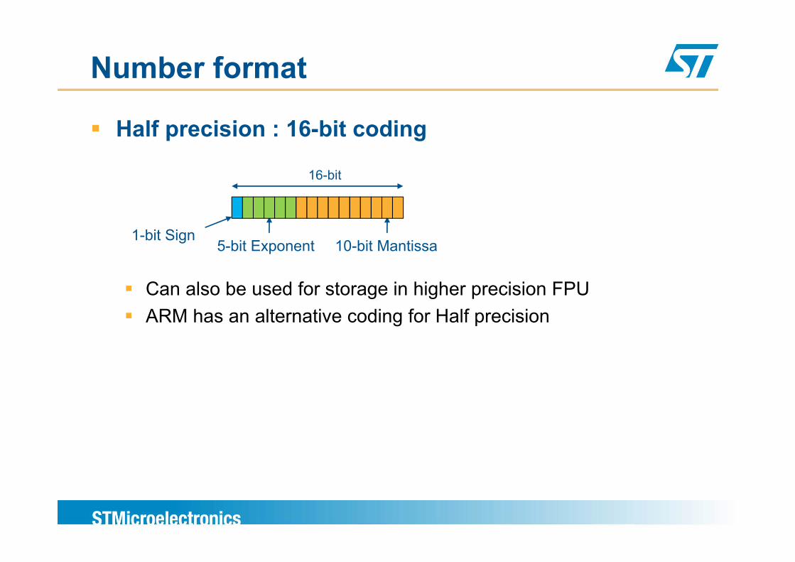
Half precision : 16-bit coding
16-bit
1-bit Sign5-bit Exponent 10-bit Mantissa
Can also be used for storage in higher precision FPUARM has an alternative coding for Half precision
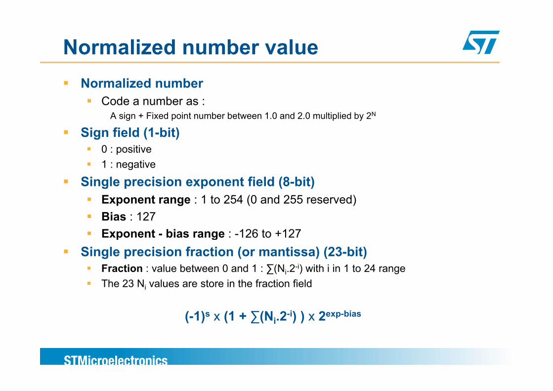
Normalized number valueNormalized number
Code a number as :A sign + Fixed point number between 1.0 and 2.0 multiplied by 2N
Sign field (1-bit)0 : positive0 : positive1 : negative
Single precision exponent field (8-bit)E t 1 t 254 (0 d 255 d)Exponent range : 1 to 254 (0 and 255 reserved)Bias : 127Exponent - bias range : -126 to +127g
Single precision fraction (or mantissa) (23-bit)Fraction : value between 0 and 1 : ∑(Ni.2-i) with i in 1 to 24 rangeThe 23 N values are store in the fraction fieldThe 23 Ni values are store in the fraction field
(-1)s x (1 + ∑(Ni.2-i) ) x 2exp-bias
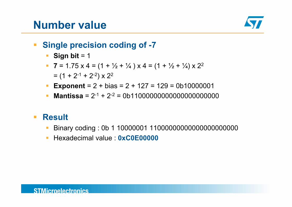
Number valueSingle precision coding of -7
Sign bit = 1Sign bit = 17 = 1.75 x 4 = (1 + ½ + ¼ ) x 4 = (1 + ½ + ¼) x 22
= (1 + 2-1 + 2-2) x 22
Exponent = 2 + bias = 2 + 127 = 129 = 0b10000001Mantissa = 2-1 + 2-2 = 0b11000000000000000000000
ResultBinary coding : 0b 1 10000001 11000000000000000000000Binary coding : 0b 1 10000001 11000000000000000000000Hexadecimal value : 0xC0E00000
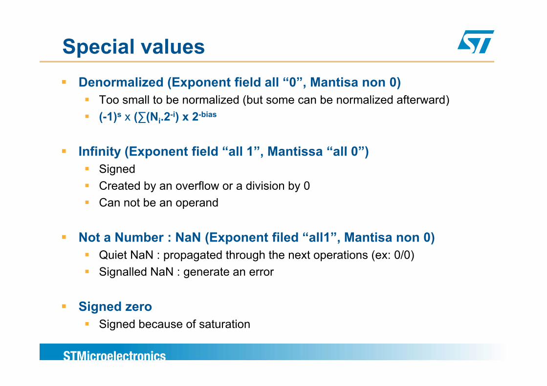
Special valuesDenormalized (Exponent field all “0”, Mantisa non 0)
Too small to be normalized (but some can be normalized afterward)( )(-1)s x (∑(Ni.2-i) x 2-bias
Infinity (Exponent field “all 1” Mantissa “all 0”)Infinity (Exponent field “all 1”, Mantissa “all 0”)SignedCreated by an overflow or a division by 0Can not be an operand
Not a Number : NaN (Exponent filed “all1” Mantisa non 0)Not a Number : NaN (Exponent filed all1 , Mantisa non 0)Quiet NaN : propagated through the next operations (ex: 0/0)Signalled NaN : generate an error
Signed zero Signed because of saturationSigned because of saturation
ARM Cortex-M FPUARM Cortex M FPU
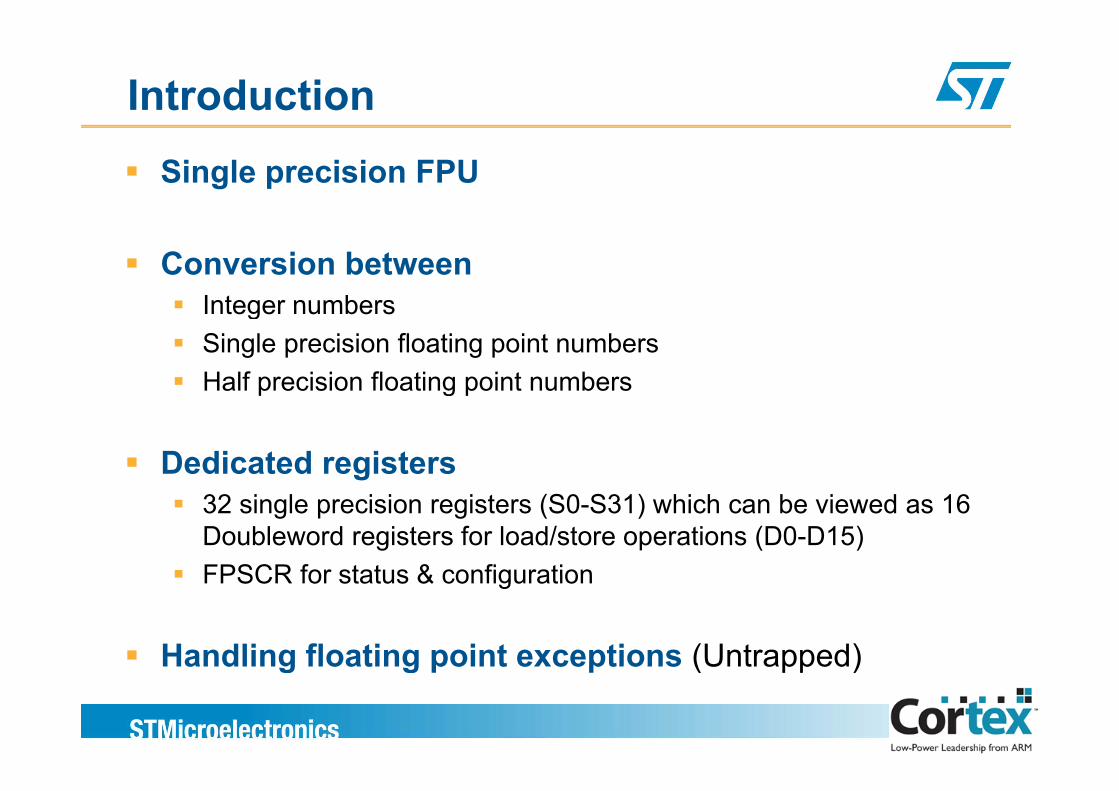
IntroductionSingle precision FPU
Conversion between Integer numbersInteger numbersSingle precision floating point numbersHalf precision floating point numbersp g p
Dedicated registers32 single precision registers (S0-S31) which can be viewed as 16 Doubleword registers for load/store operations (D0-D15)FPSCR for status & configurationFPSCR for status & configuration
Handling floating point exceptions (Untrapped)Handling floating point exceptions (Untrapped)
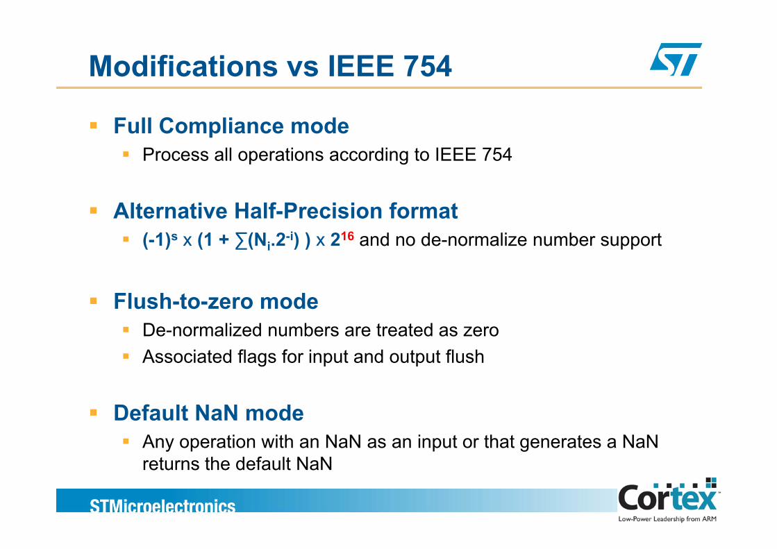
Modifications vs IEEE 754
Full Compliance modeP ll ti di t IEEE 754Process all operations according to IEEE 754
Alternative Half-Precision formatAlternative Half-Precision format(-1)s x (1 + ∑(Ni.2-i) ) x 216 and no de-normalize number support
Flush-to-zero modeDe-normalized numbers are treated as zeroAssociated flags for input and output flush
Default NaN modeAny operation with an NaN as an input or that generates a NaN returns the default NaNreturns the default NaN
Complete implementation
Cortex-M4F does NOT support all operations of IEEE 754 2008754-2008
Full implementation is done by softwareFull implementation is done by software
Unsupported operationsUnsupported operationsRemainder (% operator)Round FP number to integer-value FP numberBinary to decimal conversionsDecimal to binary conversionsDi t i f Si l P i i (SP) d D bl P i iDirect comparison of Single Precision (SP) and Double Precision (DP) values
Floating-Point Status & Control Register
Condition code bits ti d fl ( d tnegative, zero, carry and overflow (update on compare
operations)
ARM special operating mode configurationhalf-precision, default NaN and flush-to-zero mode
The rounding mode configurationnearest, zero, plus infinity or minus infinity
The exception flagsThe exception flagsInexact result flag may not be routed to the interrupt controller…
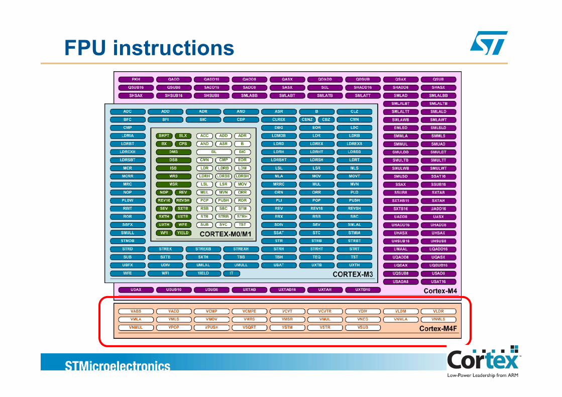
FPU instructions
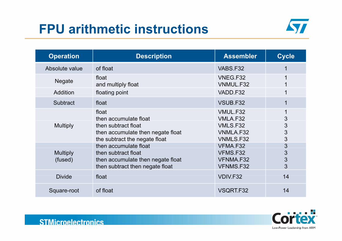
FPU arithmetic instructions
Operation Description Assembler Cycle
Absolute value of float VABS.F32 1
Negate floatand multiply float
VNEG.F32VNMUL.F32
11
Addition floating point VADD F32 1Addition floating point VADD.F32 1
Subtract float VSUB.F32 1floatthen accumulate float
VMUL.F32VMLA.F32
13
Multiplythen accumulate floatthen subtract floatthen accumulate then negate floatthe subtract the negate float
VMLA.F32VMLS.F32VNMLA.F32VNMLS.F32
3333
then accumulate float VFMA.F32 3Multiply(fused)
t e accu u ate oatthen subtract floatthen accumulate then negate floatthen subtract then negate float
3VFMS.F32VFNMA.F32VFNMS.F32
3333
Di id fl t VDIV F32 14Divide float VDIV.F32 14
Square-root of float VSQRT.F32 14
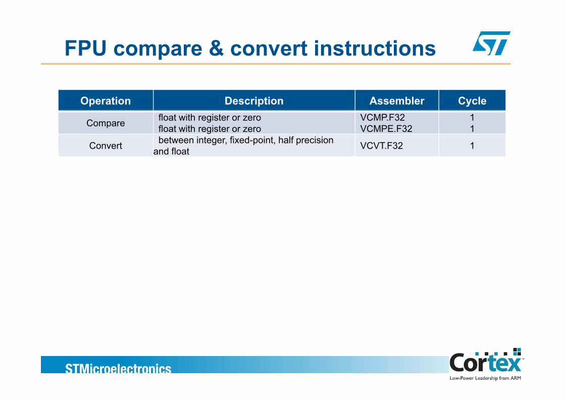
FPU compare & convert instructions
Operation Description Assembler Cycle
Compare float with register or zerofloat with register or zero
VCMP.F32VCMPE.F32
11
Convert between integer, fixed-point, half precision and float VCVT.F32 1
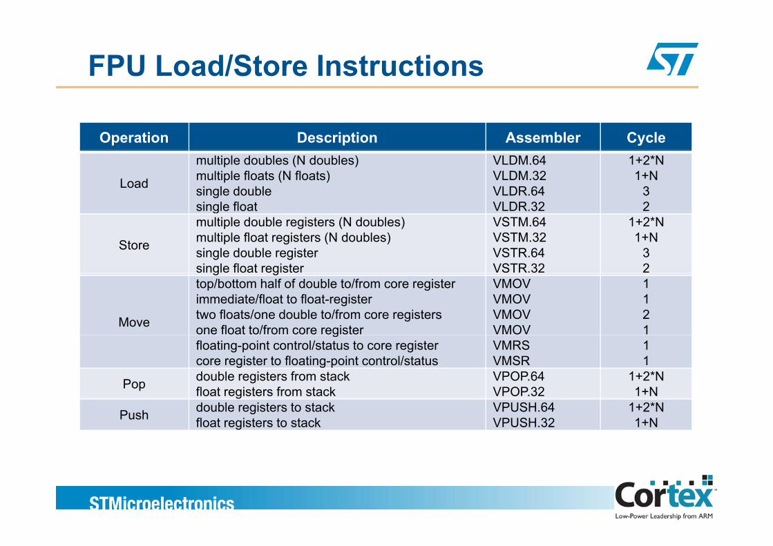
FPU Load/Store Instructions
Operation Description Assembler Cycle
Load
multiple doubles (N doubles)multiple floats (N floats)single doublesingle float
VLDM.64VLDM.32VLDR.64VLDR.32
1+2*N1+N
32g
Store
multiple double registers (N doubles)multiple float registers (N doubles)single double registersingle float register
VSTM.64VSTM.32VSTR.64VSTR.32
1+2*N1+N
32g g
Move
top/bottom half of double to/from core registerimmediate/float to float-registertwo floats/one double to/from core registersone float to/from core register
VMOVVMOVVMOVVMOV
1121g
floating-point control/status to core registercore register to floating-point control/status
VMRSVMSR
11
Pop double registers from stackfloat registers from stack
VPOP.64VPOP.32
1+2*N1+Ng
Push double registers to stackfloat registers to stack
VPUSH.64VPUSH.32
1+2*N1+N
Extensive tools and SWExtensive tools and SW
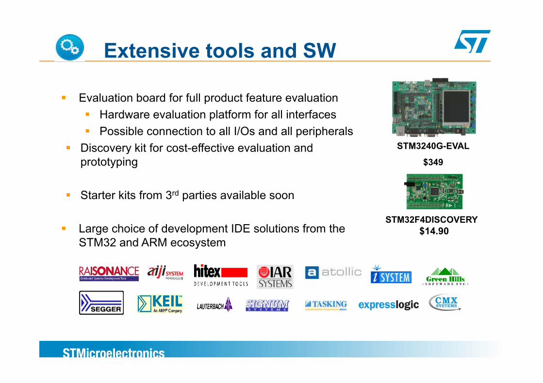
Extensive tools and SW
Evaluation board for full product feature evaluationHardware evaluation platform for all interfacesPossible connection to all I/Os and all peripherals
Discovery kit for cost effective evaluation and STM3240G-EVALDiscovery kit for cost-effective evaluation and prototyping
St t kit f 3rd ti il bl
STM3240G EVAL
$349
Starter kits from 3rd parties available soon
Large choice of development IDE solutions from the STM32F4DISCOVERY
$14.90STM32 and ARM ecosystem
$
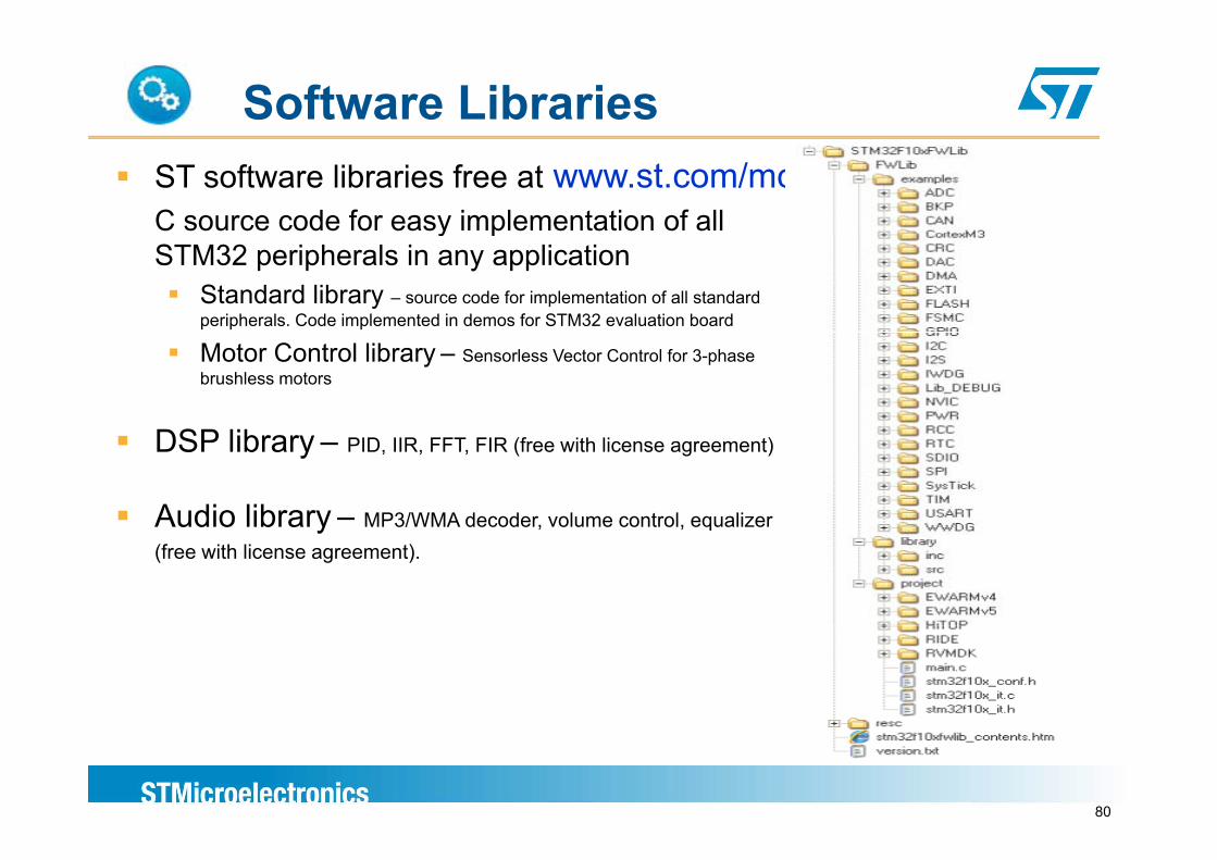
Software LibrariesST software libraries free at www.st.com/mcuC source code for easy implementation of all y pSTM32 peripherals in any application
Standard library – source code for implementation of all standard peripherals. Code implemented in demos for STM32 evaluation board
Motor Control library – Sensorless Vector Control for 3-phase brushless motors
DSP libDSP library – PID, IIR, FFT, FIR (free with license agreement)
Audio library – MP3/WMA decoder, volume control, equalizer
ST engineered, tested, documented and freey , , q
(free with license agreement).
80
DSP lib provided for free by ARM
The benefits of software libraries for Cortex-M4Enables end user to develop applications fasterEnables end user to develop applications faster
Keeps end user abstracted from low level programmingBenchmarking vehicle during system developmentClear competitive positioning against incumbent DSP/DSC offeringsClear competitive positioning against incumbent DSP/DSC offeringsAccelerate third party software development
Keeping it easy to access for end userMinimal entry barrier - very easy to access and use
One standard library – no duplicated effortsARM channels effort/resources with software partnerValue add through another level of software – eg: filter config tools
81
DSP lib function list snapshot
Basic math – vector mathematicsFast math – sin, cos, sqrt etcInterpolation linear bilinearInterpolation – linear, bilinearComplex mathStatistics – max, min,RMS etcFiltering – IIR, FIR, LMS etcTransforms – FFT(real and complex) , Cosine transform etcMatrix functionsPID ControllerSupport functions – copy/fill arrays data type conversions etcSupport functions – copy/fill arrays, data type conversions etc
82
STM32 F4 Hardware toolsSTM32 F4 Hardware tools
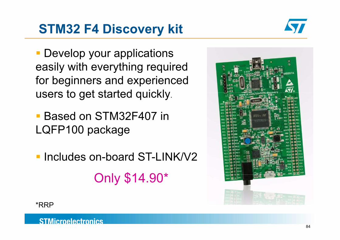
STM32 F4 Discovery kit
Develop your applications easily with everything requiredeasily with everything required for beginners and experienced users to get started quicklyusers to get started quickly.
Based on STM32F407 in ased o S 3 0LQFP100 package
Includes on-board ST-LINK/V2
O l $14 90*Only $14.90*
84
*RRP
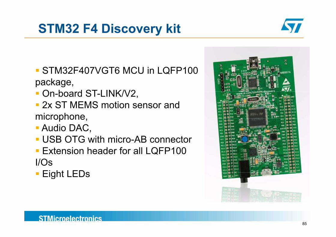
STM32 F4 Discovery kit
STM32F407VGT6 MCU in LQFP100 package,
On board ST LINK/V2On-board ST-LINK/V2, 2x ST MEMS motion sensor and
microphonemicrophone,Audio DAC,USB OTG with micro-AB connectorExtension header for all LQFP100
I/OsEight LEDsEight LEDs
85
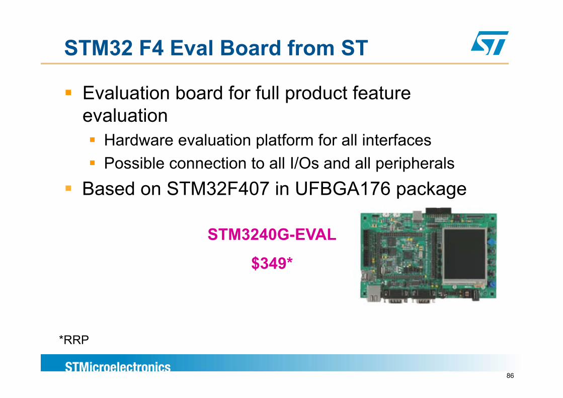
STM32 F4 Eval Board from ST
Evaluation board for full product feature l tievaluation
Hardware evaluation platform for all interfacesPossible connection to all I/Os and all peripherals
Based on STM32F407 in UFBGA176 package
STM3240G-EVAL
$349*
86
*RRP
Starter kits from 3rd parties
STM32F4 starter kits from IAR and Keil available i Q4 2011in Q4 2011
Order codes: IAR: STM3240G-SK/IARIAR: STM3240G SK/IARKEIL: STM3240G-SK/KEI
87

Thank you
www.st.com/stm32f4
High PerformanceHigh Performance
How to benchmark microsThe core
The first think to consider is the core : no wait states shall be introduced to decrease the resultAs a consequence, the maximum frequency achievable is the maximum frequency of the Flash
The compiler used for the code generation of the benchmark have a significant influence on the result : for a same core, you can have t diff t b h k lt ith t diff t iltwo different benchmark result with two different compilers
90
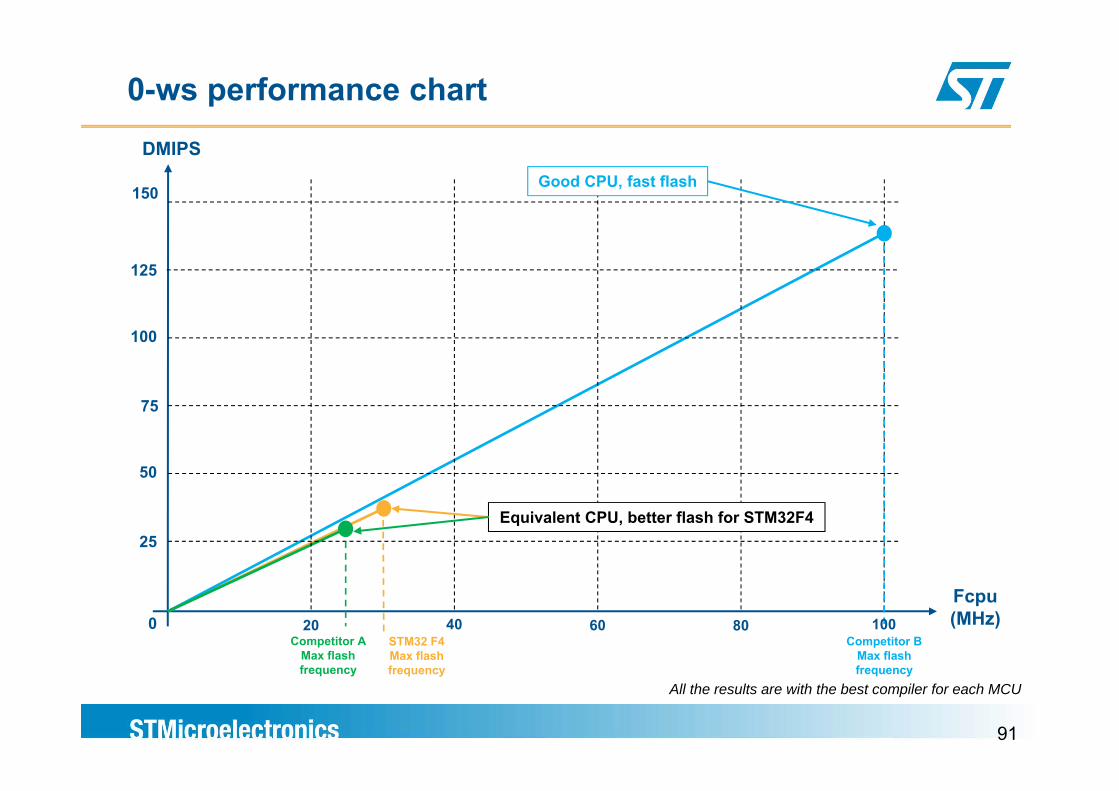
0-ws performance chartDMIPS
150Good CPU, fast flash
125
100
50
75
25Equivalent CPU, better flash for STM32F4
Fcpu(MHz)
Competitor AMax flash
Competitor BMax flash
STM32 F4Max flash
40 8020 60 1000
91
frequency frequencyfrequencyAll the results are with the best compiler for each MCU
How to benchmark microsThe flash acceleration
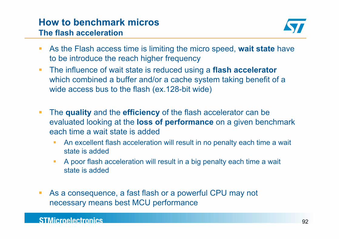
As the Flash access time is limiting the micro speed, wait state have to be introduce the reach higher frequencyThe influence of wait state is reduced using a flash accelerator which combined a buffer and/or a cache system taking benefit of a wide access bus to the flash (ex.128-bit wide)( )
The quality and the efficiency of the flash accelerator can be l t d l ki t th l f f i b h kevaluated looking at the loss of performance on a given benchmark
each time a wait state is added An excellent flash acceleration will result in no penalty each time a wait state is addedA poor flash acceleration will result in a big penalty each time a wait state is added
As a consequence, a fast flash or a powerful CPU may not b t MCU f
92
necessary means best MCU performance
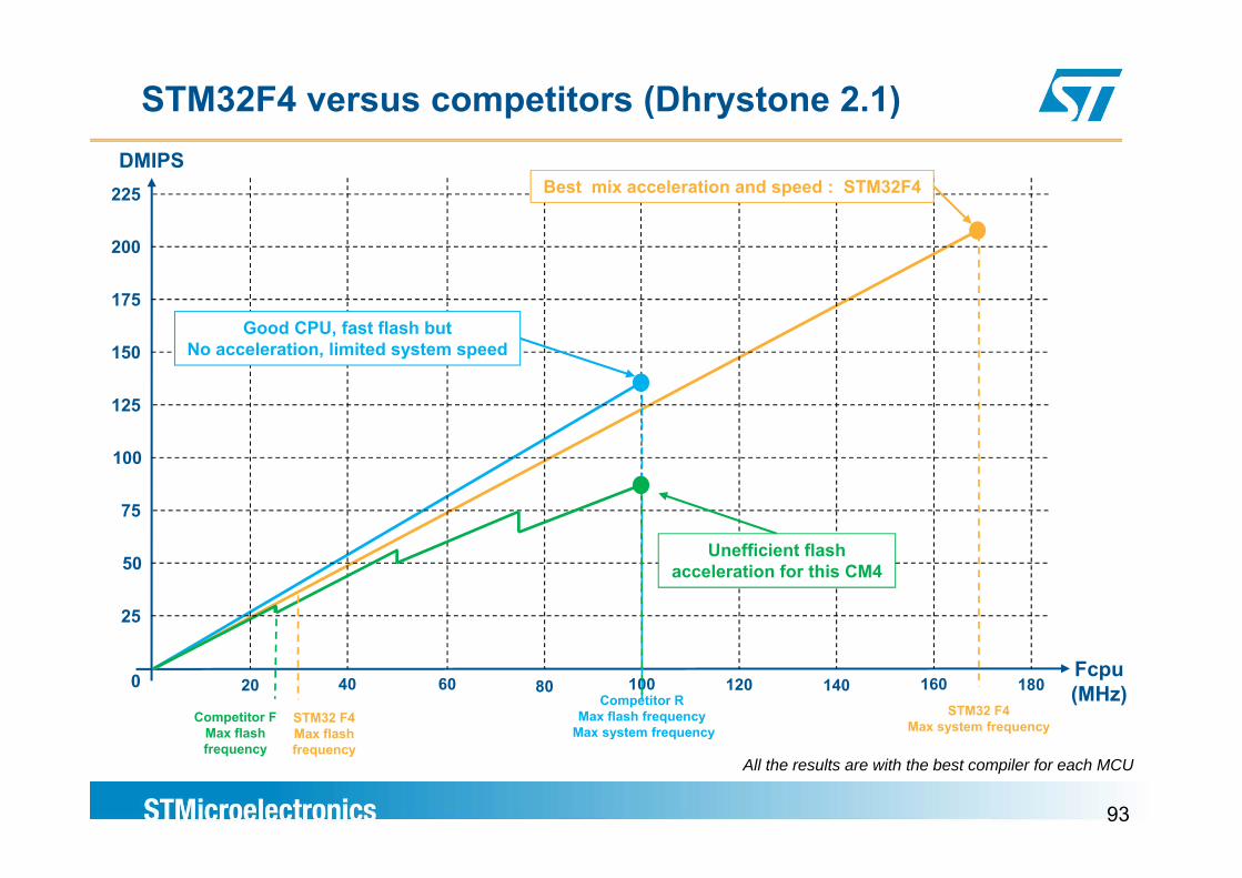
STM32F4 versus competitors (Dhrystone 2.1)DMIPS
225 Best mix acceleration and speed : STM32F4
175
200
Good CPU, fast flash but150
125
No acceleration, limited system speed
100
75
50
25
Unefficient flash acceleration for this CM4
Fcpu (MHz)
STM32 F4Max system frequency
4020 80 14060 100 120 160Competitor R
Max flash frequencyMax system frequency
Competitor FMax flash
STM32 F4Max flash
0 180
93
y q yfrequency
Max flash frequency
All the results are with the best compiler for each MCU
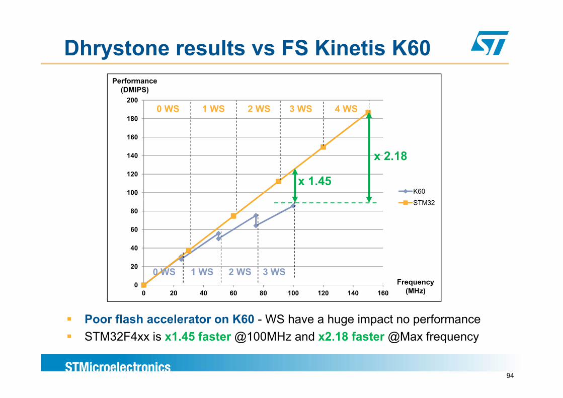
Dhrystone results vs FS Kinetis K60
2000 WS 1 WS 2 WS 3 WS 4 WS
Performance(DMIPS)
140
160
180
x 2 18
0 WS 1 WS 2 WS 3 WS 4 WS
100
120
140
K60
x 2.18
x 1.45
60
80STM32
0
20
40
0 WS 1 WS 2 WS 3 WSFrequency
(MH )0 20 40 60 80 100 120 140 160 (MHz)
Poor flash accelerator on K60 - WS have a huge impact no performanceSTM32F4xx is x1 45 faster @100MHz and x2 18 faster @Max frequency
94
STM32F4xx is x1.45 faster @100MHz and x2.18 faster @Max frequency
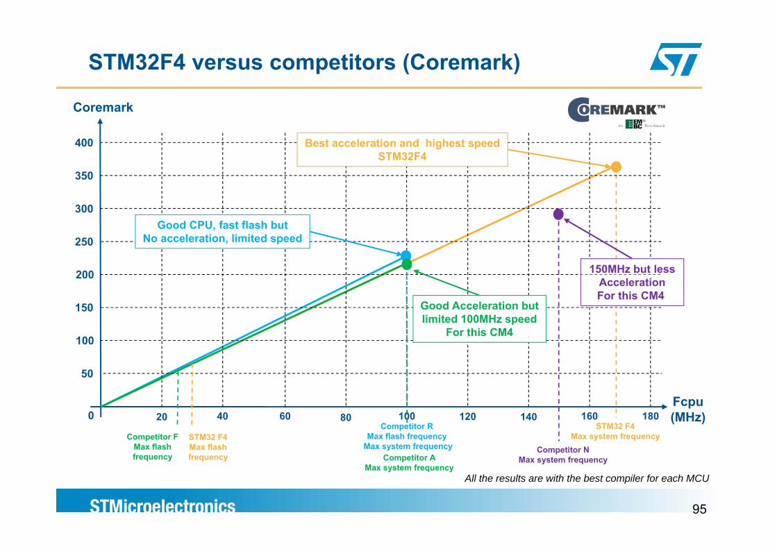
STM32F4 versus competitors (Coremark)
Coremark
400 Best acceleration and highest speed
300
350
STM32F4
200
300
250Good CPU, fast flash but
No acceleration, limited speed
150MHz but less
100
200
150 Good Acceleration but limited 100MHz speed
For this CM4
AccelerationFor this CM4
Fcp
100
50
Fcpu (MHz)
STM32 F4Max system frequency
4020 80 14060 100 120 160Competitor R
Max flash frequencyMax system frequency
Competitor FMax flash frequency
STM32 F4Max flash frequency Competitor A
0
Competitor NMax system frequency
180
95
y pMax system frequency
Max system frequency
All the results are with the best compiler for each MCU
Thank you
www.st.com/stm32f4