steve parkes , chris mcclements -...
TRANSCRIPT

SpaceFibre
Steve Parkes1, Chris McClements1, Martin Dunstan1
Albert Ferrer2, Alberto Gonzalez2
1Space Technology Centre, University of Dundee. UK
2STAR-Dundee Ltd, UK 1
Contents SpaceFibre Applications SpaceFibre Network Level SpaceFibre Standard Update
2
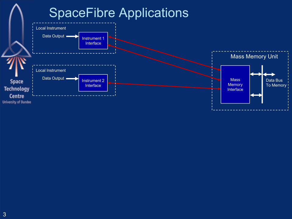
SpaceFibre Applications
3
Instrument 2Interface
Data Output
Local Instrument
Instrument 1Interface
Data Output
Local Instrument
Data BusTo Memory
Mass Memory Unit
Mass MemoryInterface

SpaceFibre Applications
4
Instrument 2Interface
Data Output
SpaceWireTo
SpaceFibre Bridge
SpaceWireInstrument
SpaceWireInstrument
SpaceWireInstrument
SpaceWireInstrument
Data Output
Data Output
Local Instruments
Remote Instruments
Local Instrument
Instrument 1Interface
Data Output
Local Instrument
Data BusTo Memory
Mass Memory Unit
Mass MemoryInterface
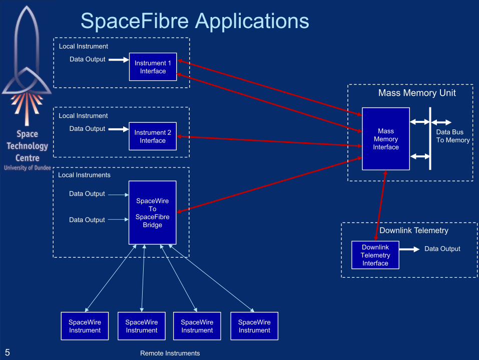
SpaceFibre Applications
5
Instrument 2Interface
Data Output
SpaceWireTo
SpaceFibre Bridge
SpaceWireInstrument
SpaceWireInstrument
SpaceWireInstrument
SpaceWireInstrument
Data Output
Data Output
Local Instruments
Remote Instruments
Local Instrument
Instrument 1Interface
Data Output
Local Instrument
Data BusTo Memory
Mass Memory Unit
Mass MemoryInterface
Downlink TelemetryInterface
Data Output
Downlink Telemetry
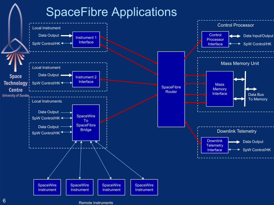
SpaceFibre Applications
6
Instrument 2InterfaceSpW Control/HK
Data Output
SpaceWireTo
SpaceFibre Bridge
SpaceWireInstrument
SpaceWireInstrument
SpaceWireInstrument
SpaceWireInstrument
SpW Control/HKData Output
SpW Control/HKData Output
Local Instruments
Remote Instruments
Local Instrument
SpaceFibreRouter
Instrument 1InterfaceSpW Control/HK
Data Output
Local Instrument
Mass MemoryInterface Data Bus
To Memory
Mass Memory Unit
Downlink TelemetryInterface SpW Control/HK
Data Output
Downlink Telemetry
ControlProcessorInterface SpW Control/HK
Data Input/Output
Control Processor

Principal On-board Communications Instrument
– Data to mass-memory– Configuration and control– Housekeeping
Mass memory– Data from instruments– Data to downlink– Configuration and control– Housekeeping
Downlink– Data from mass-memory– Configuration and control– Housekeeping
7
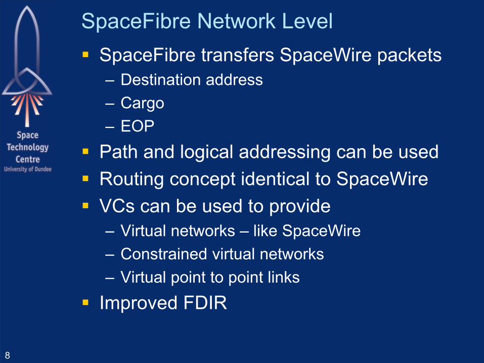
SpaceFibre Network Level SpaceFibre transfers SpaceWire packets
– Destination address– Cargo– EOP
Path and logical addressing can be used Routing concept identical to SpaceWire VCs can be used to provide
– Virtual networks – like SpaceWire– Constrained virtual networks– Virtual point to point links
Improved FDIR
8

SpaceFibre Routing Switch
9
Routing SwitchMatrix
SpaceFibreInterface
VC
VC
VC
VC
VC
SpaceFibreInterface
VC
VC
VC
VC
VC
SpaceFibreInterface
VC
VC
VC
VC
VC
SpaceFibreInterface
VC
VC
VC
VC
VC
ConfigurationPort
Port 2 Port 3
Port 1 Port 4
SpaceFibrePort 2
SpaceFibrePort 1
SpaceFibrePort 3
SpaceFibrePort 4
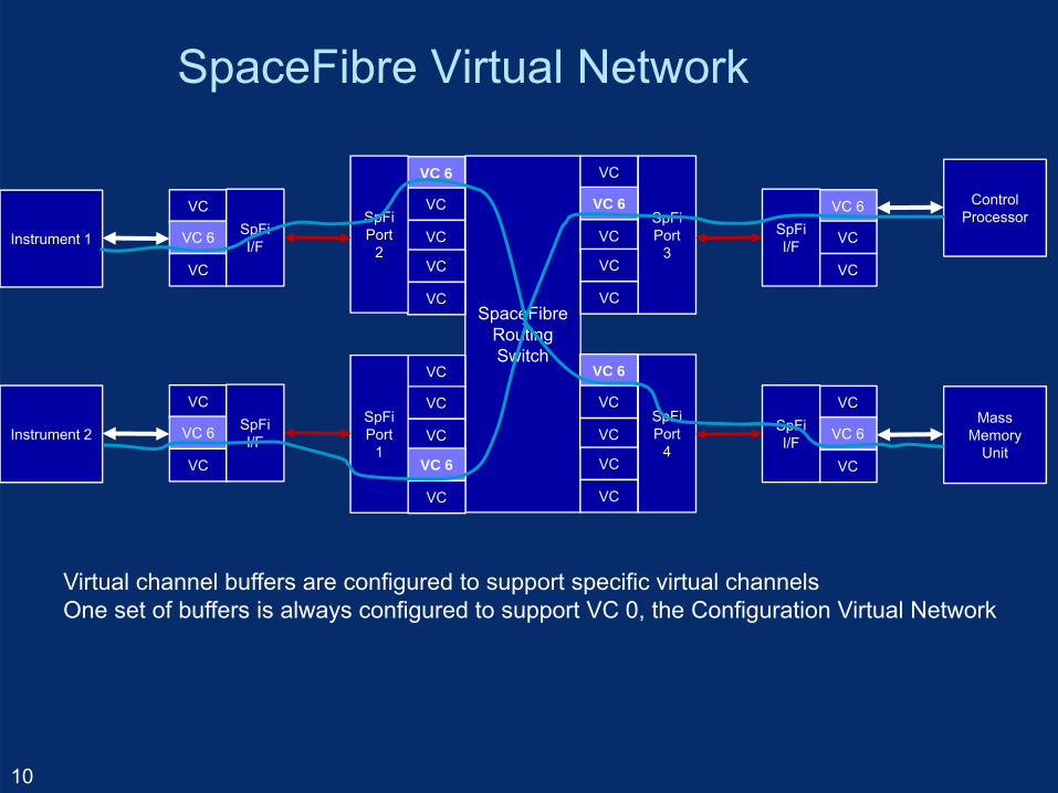
SpaceFibre Virtual Network
10
SpaceFibreRoutingSwitch
VC
VC 6
VC
VC
VC
VC 6
VC
VC
VC
VC
VC 6
VC
VC
VC
VC
VC
VC
VC
VC 6
VC
SpFiPort
3
SpFiPort
4
SpFiPort
2
SpFiPort
1
VC 6
VC
VC
SpFiI/F
ControlProcessor
VC
VC 6
VC
SpFiI/F
MassMemory
Unit
VC
VC 6
VC
SpFiI/FInstrument 2
VC
VC 6
VC
SpFiI/FInstrument 1
Virtual channel buffers are configured to support specific virtual channelsOne set of buffers is always configured to support VC 0, the Configuration Virtual Network

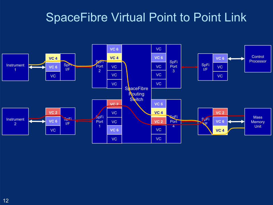
SpaceFibre Virtual Point to Point Link
11
SpaceFibreRoutingSwitch
VC
VC 6
VC
VC
VC
VC 6
VC 4
VC 2
VC
VC
VC 6
VC 4
VC
VC
VC
VC 2
VC
VC
VC 6
VC
SpFiPort
3
SpFiPort
4
SpFiPort
2
SpFiPort
1
VC 6
VC
VC
SpFiI/F
ControlProcessor
VC 2
VC 6
VC 4
SpFiI/F
MassMemory
Unit
VC 2
VC 6
VC
SpFiI/F
Instrument 2
VC 4
VC 6
VC
SpFiI/F
Instrument 1
SpaceFibre Virtual Point to Point Link
12
SpaceFibreRoutingSwitch
VC
VC 6
VC
VC
VC
VC 6
VC 4
VC 2
VC
VC
VC 6
VC 4
VC
VC
VC
VC 2
VC
VC
VC 6
VC
SpFiPort
3
SpFiPort
4
SpFiPort
2
SpFiPort
1
VC 6
VC
VC
SpFiI/F
ControlProcessor
VC 2
VC 6
VC 4
SpFiI/F
MassMemory
Unit
VC 2
VC 6
VC
SpFiI/F
Instrument 2
VC 4
VC 6
VC
SpFiI/F
Instrument 1
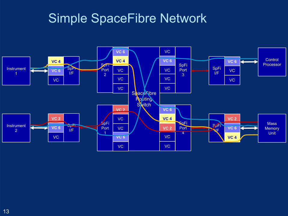
Simple SpaceFibre Network
13
SpaceFibreRoutingSwitch
VC
VC 6
VC
VC
VC
VC 6
VC 4
VC 2
VC
VC
VC 6
VC 4
VC
VC
VC
VC 2
VC
VC
VC 6
VC
SpFiPort
3
SpFiPort
4
SpFiPort
2
SpFiPort
1
VC 6
VC
VC
SpFiI/F
ControlProcessor
VC 2
VC 6
VC 4
SpFiI/F
MassMemory
Unit
VC 2
VC 6
VC
SpFiI/F
Instrument 2
VC 4
VC 6
VC
SpFiI/F
Instrument 1
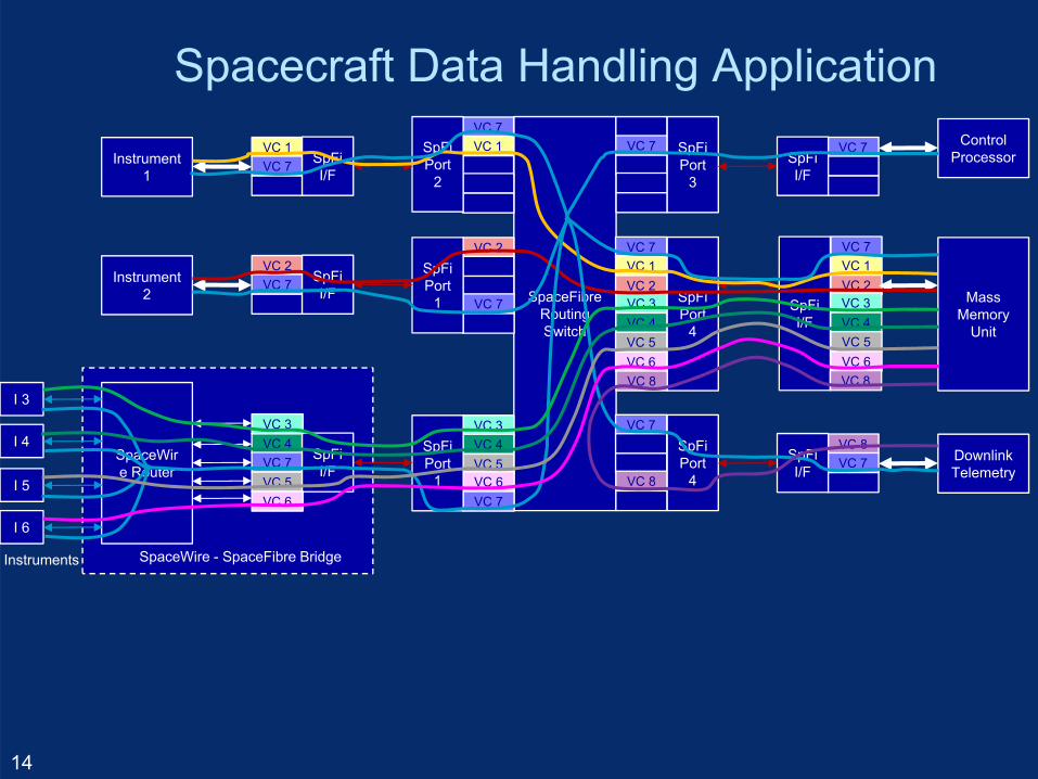
Spacecraft Data Handling Application
14
SpaceWire - SpaceFibre Bridge
VC 7VC 1VC 2VC 3VC 4
SpFiI/F
VC 5VC 6VC 8
SpaceFibreRoutingSwitch
VCVC 7VCVCVC
VC 7VC 1VC 2VC 3VC 4
VC 7VC 1VCVCVC
VC 2VCVC
VC 7VC
SpFiPort
3
SpFiPort
4
SpFiPort
2
SpFiPort
1
VC 7VCVC
SpFiI/F
ControlProcessor
MassMemory
Unit
VC 2VC 7VC
SpFiI/F
Instrument 2
VC 1VC 7VC
SpFiI/F
Instrument 1
VC 7VC VC
VC 8VC
VC 3VC 4VC 5VC 6VC 7
SpFiPort
4
SpFiPort
1
VC 8VC 7VC
SpFiI/F
DownlinkTelemetry
VC 4VC 7VC 5
SpFiI/F
SpaceWire Router
I 3
I 4
I 5
I 6
VC 6
VC 3
VC 5VC 6VC 8
Instruments
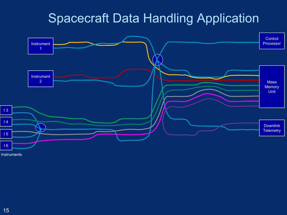
Spacecraft Data Handling Application
15
ControlProcessor
MassMemory
Unit
Instrument 2
Instrument 1
DownlinkTelemetry
I 3
I 4
I 5
I 6
Instruments
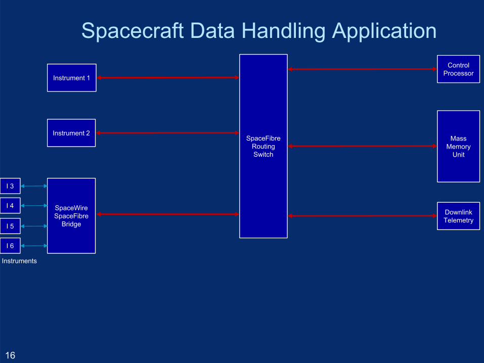
Spacecraft Data Handling Application
16
SpaceFibreRoutingSwitch
ControlProcessor
MassMemory
Unit
Instrument 2
Instrument 1
DownlinkTelemetry
SpaceWire SpaceFibre
Bridge
I 3
I 4
I 5
I 6
Instruments
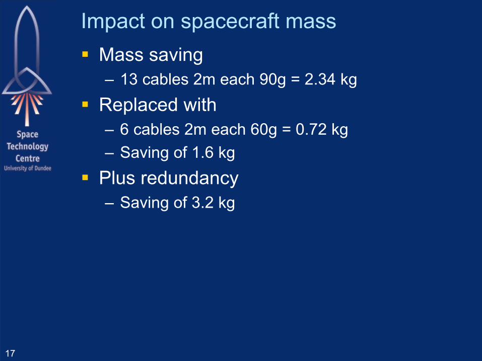
Impact on spacecraft mass Mass saving
– 13 cables 2m each 90g = 2.34 kg Replaced with
– 6 cables 2m each 60g = 0.72 kg– Saving of 1.6 kg
Plus redundancy– Saving of 3.2 kg
17

Addition FDIR capability
18
SpaceFibreRoutingSwitch
VC
VC 6
VC
VC
VC
VC 6
VC 4
VC 2
VC
VC
VC 6
VC 4
VC
VC
VC
VC 2
VC
VC
VC 6
VC
SpFiPort
3
SpFiPort
4
SpFiPort
2
SpFiPort
1
VC 6
VC
VC
SpFiI/F
ControlProcessor
VC 2
VC 6
VC 4
SpFiI/F
MassMemory
Unit
VC 2
VC 6
VC
SpFiI/F
Instrument 2
VC 4
VC 6
VC
SpFiI/F
Instrument 1
Not allowed to use this Port since no VC 4
SpaceWire packet discarded
Can only route to same VC
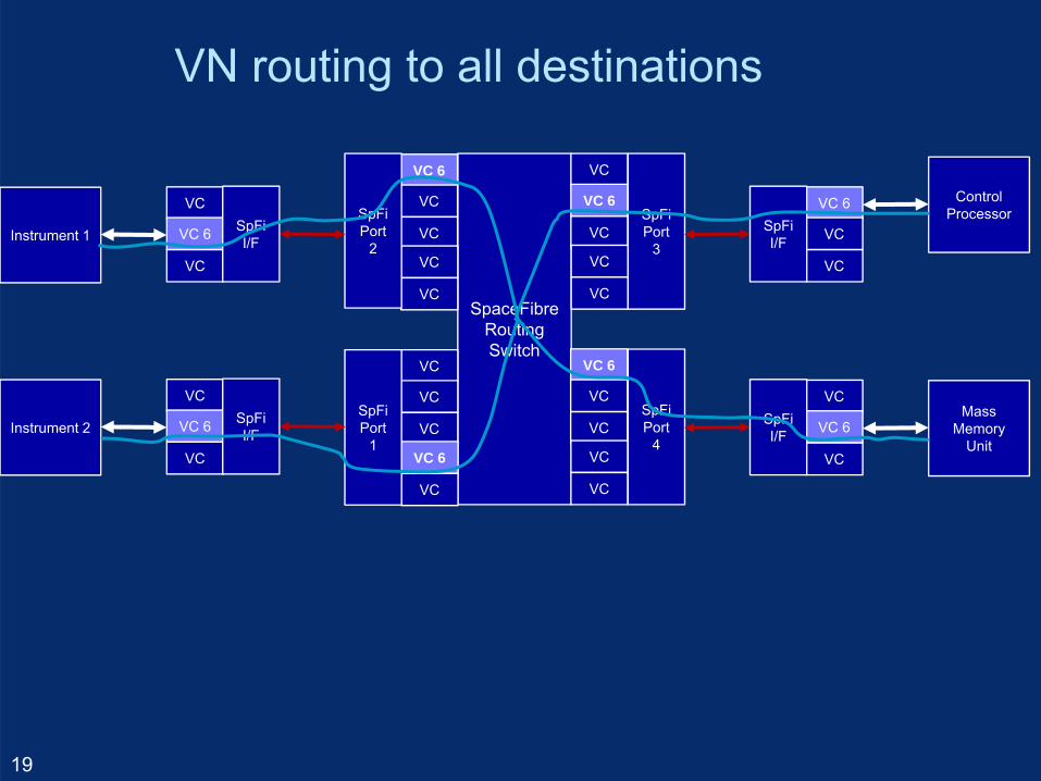
VN routing to all destinations
19
SpaceFibreRoutingSwitch
VC
VC 6
VC
VC
VC
VC 6
VC
VC
VC
VC
VC 6
VC
VC
VC
VC
VC
VC
VC
VC 6
VC
SpFiPort
3
SpFiPort
4
SpFiPort
2
SpFiPort
1
VC 6
VC
VC
SpFiI/F
ControlProcessor
VC
VC 6
VC
SpFiI/F
MassMemory
Unit
VC
VC 6
VC
SpFiI/FInstrument 2
VC
VC 6
VC
SpFiI/FInstrument 1
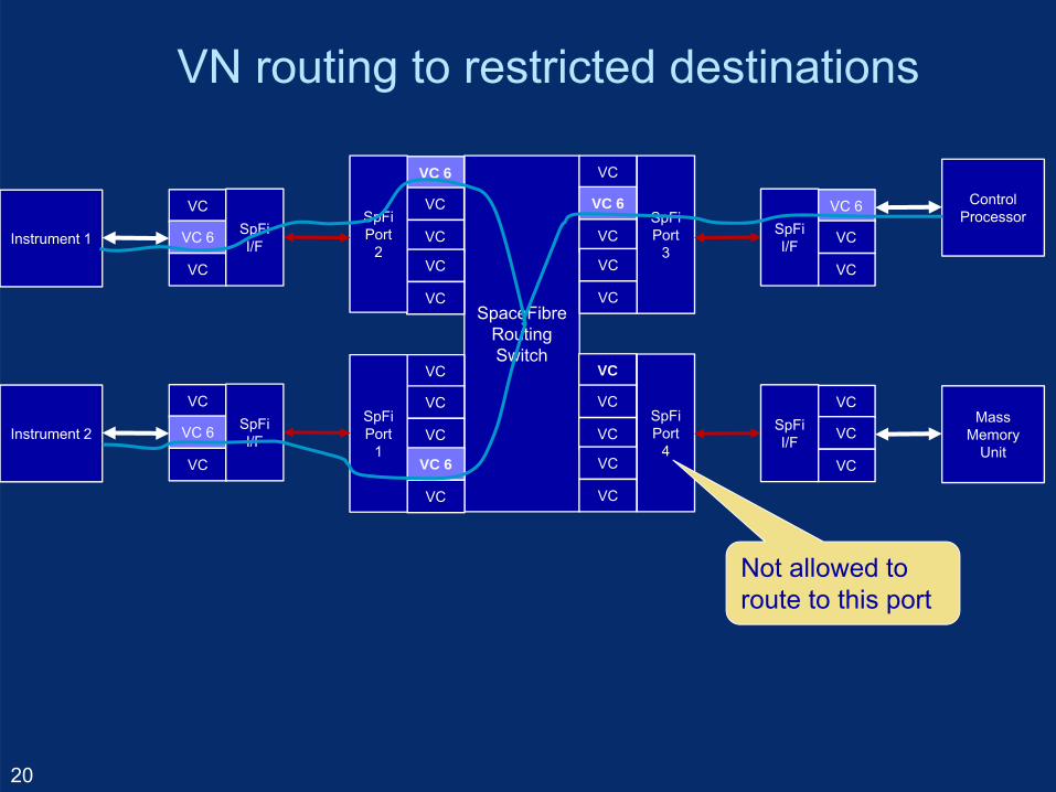
VN routing to restricted destinations
20
SpaceFibreRoutingSwitch
VC
VC 6
VC
VC
VC
VC
VC
VC
VC
VC
VC 6
VC
VC
VC
VC
VC
VC
VC
VC 6
VC
SpFiPort
3
SpFiPort
4
SpFiPort
2
SpFiPort
1
VC 6
VC
VC
SpFiI/F
ControlProcessor
VC
VC
VC
SpFiI/F
MassMemory
Unit
VC
VC 6
VC
SpFiI/FInstrument 2
VC
VC 6
VC
SpFiI/FInstrument 1
Not allowed to route to this port
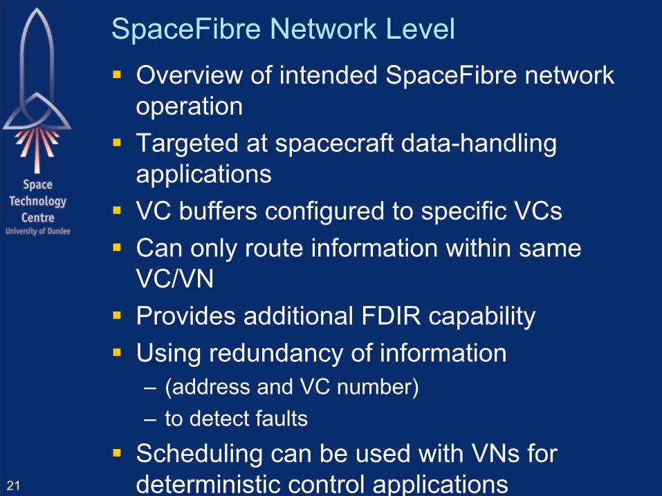
SpaceFibre Network Level Overview of intended SpaceFibre network
operation Targeted at spacecraft data-handling
applications VC buffers configured to specific VCs Can only route information within same
VC/VN Provides additional FDIR capability Using redundancy of information
– (address and VC number)– to detect faults
Scheduling can be used with VNs for deterministic control applications21
SpaceFibre Standard Update
22
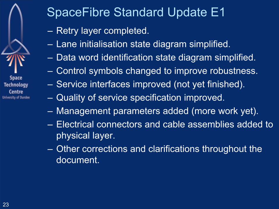
SpaceFibre Standard Update E1– Retry layer completed.– Lane initialisation state diagram simplified.– Data word identification state diagram simplified.– Control symbols changed to improve robustness.– Service interfaces improved (not yet finished).– Quality of service specification improved.– Management parameters added (more work yet).– Electrical connectors and cable assemblies added to
physical layer.– Other corrections and clarifications throughout the
document.
23
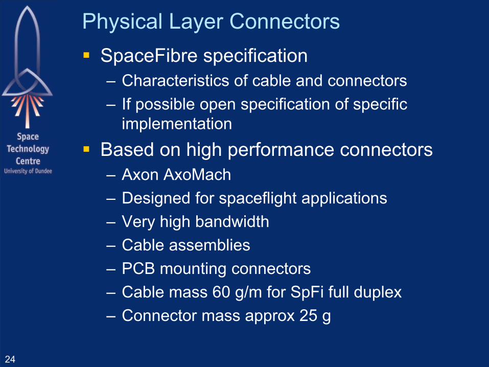
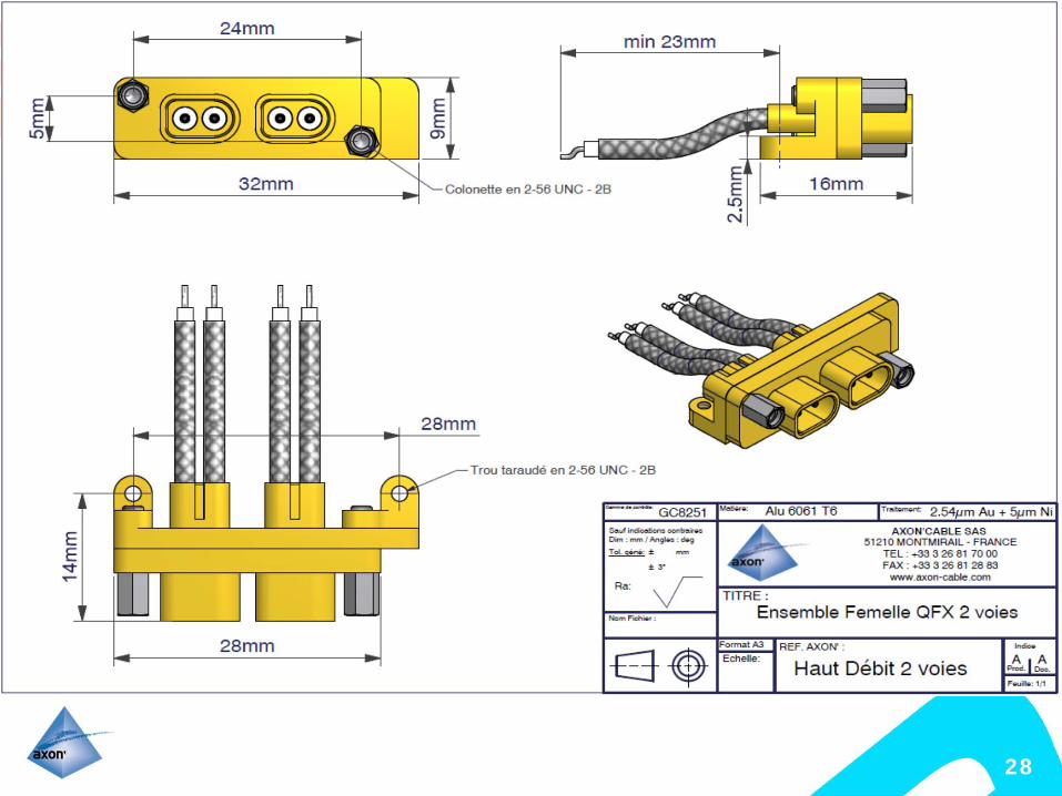
Physical Layer Connectors SpaceFibre specification
– Characteristics of cable and connectors– If possible open specification of specific
implementation Based on high performance connectors
– Axon AxoMach– Designed for spaceflight applications– Very high bandwidth– Cable assemblies– PCB mounting connectors– Cable mass 60 g/m for SpFi full duplex– Connector mass approx 25 g
24
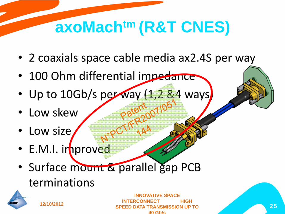
axoMachtm (R&T CNES)
• 2 coaxials space cable media ax2.4S per way• 100 Ohm differential impedance• Up to 10Gb/s per way (1,2 &4 ways)• Low skew• Low size• E.M.I. improved• Surface mount & parallel gap PCB terminations
12/10/2012
INNOVATIVE SPACE INTERCONNECT HIGH
SPEED DATA TRANSMISSION UP TO 40 Gb/s
25
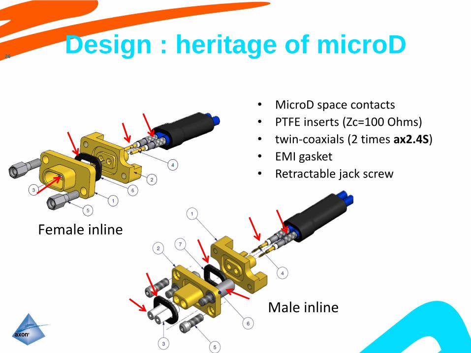
Design : heritage of microD
• MicroD space contacts• PTFE inserts (Zc=100 Ohms)• twin‐coaxials (2 times ax2.4S)• EMI gasket• Retractable jack screw
26
INNOVATIVE SPACE INTERCONNECT HIGH
SPEED DATA TRANSMISSION UP TO 40 Gb/s
Female inline
Male inline
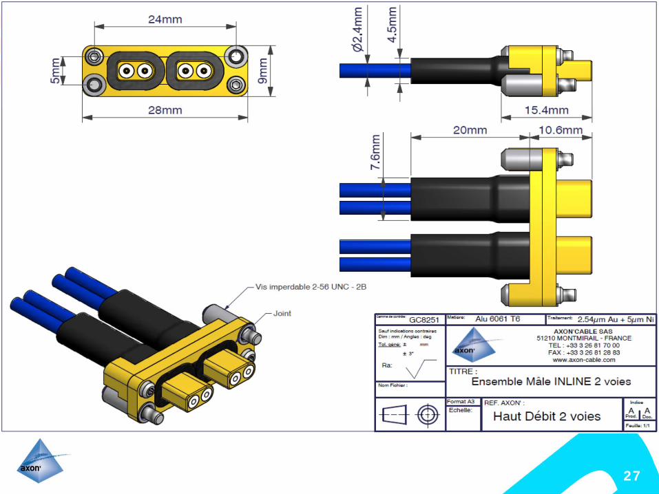
27
28
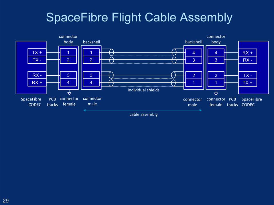
SpaceFibre Flight Cable Assembly
29
12
34
43
21
cable assembly
connectormale
connectormale
Individual shields
backshell
43
21
TX -TX +
RX +RX -
connectorfemale
PCBtracks
SpaceFibreCODEC
connectorbodybackshell
TX +TX -
12
34
RX -RX +
PCBtracks
SpaceFibreCODEC
connectorbody
connectorfemale

SpaceFibre Flight/EGSE Cable Assembly
30

SpaceFibre EGSE Cable Assemblies External Serial ATA (eSATA) connectors
used– Low cost– Small– High performance
Crossover cable assemblies
31
SpaceFibre EGSE Cable Assembly
32
23
1
4
56
7
65
7
4
32
1
shield
cable assembly
cable receptacle
cable receptacle
shield
B +B -
GND
GND
A -A +
GND
TX -TX +
RX +RX -
deviceplug
PCBtracks
SpaceFibreCODEC
TX +TX -
A +A -
GND
GND
B -B +
GND
RX -RX +
deviceplug
PCBtracks
SpaceFibreCODEC
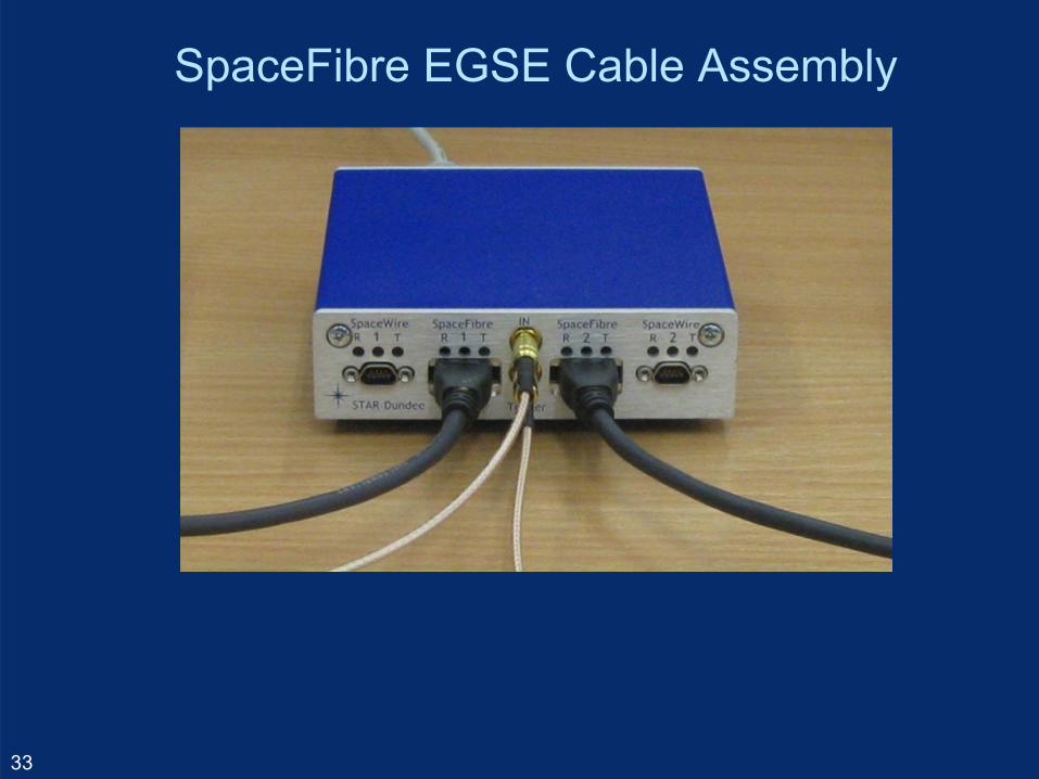
SpaceFibre EGSE Cable Assembly
33
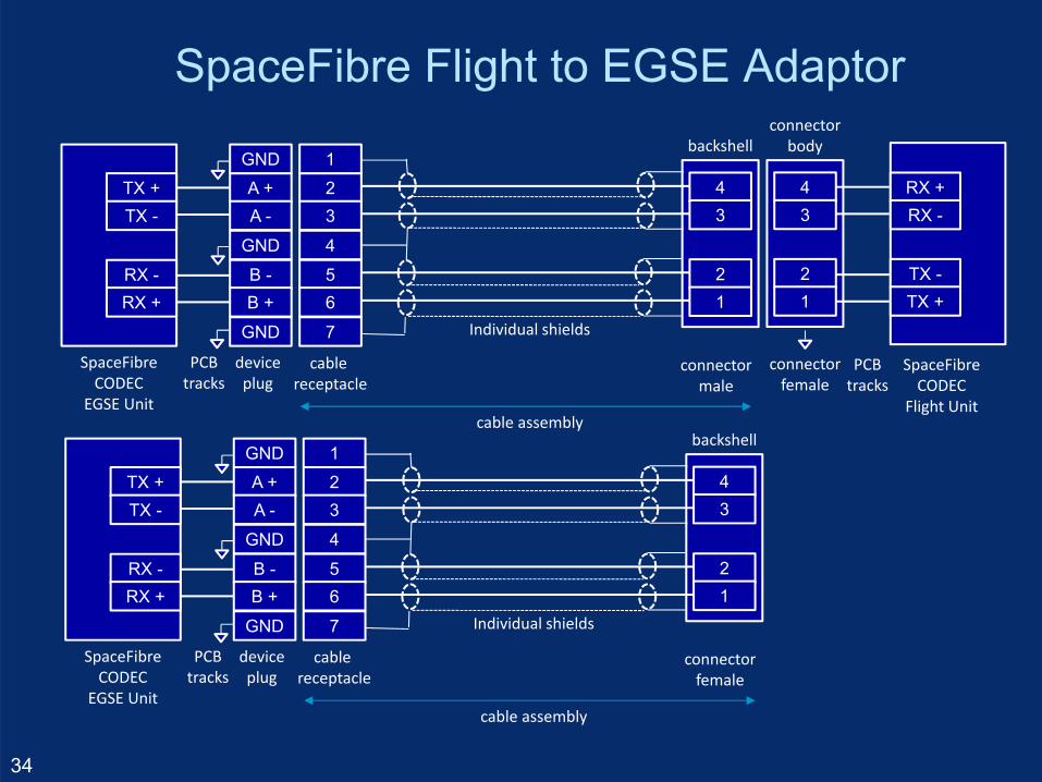
SpaceFibre Flight to EGSE Adaptor
34
43
21
cable assembly
connectormale
Individual shields
backshell
43
21
TX -TX +
RX +RX -
connectorfemale
PCBtracks
SpaceFibreCODEC
Flight Unit
connectorbody
23
1
4
56
7
cable receptacle
TX +TX -
A +A -
GND
GND
B -B +
GND
RX -RX +
deviceplug
PCBtracks
SpaceFibreCODEC
EGSE Unit
43
21
cable assembly
connectorfemale
Individual shields
backshell
23
1
4
56
7
cable receptacle
TX +TX -
A +A -
GND
GND
B -B +
GND
RX -RX +
deviceplug
PCBtracks
SpaceFibreCODEC
EGSE Unit
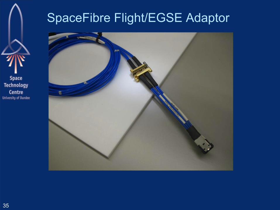
SpaceFibre Flight/EGSE Adaptor
35
Quality of service Reminder about the QoS mechanism
– Bandwidth reserved– Priority– Scheduled
36
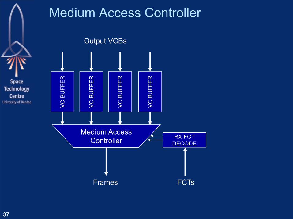
Medium Access Controller
37
Frames FCTs
VC B
UFF
ER
RX FCTDECODE
Output VCBs
Medium AccessController
VC B
UFF
ER
VC B
UFF
ER
VC B
UFF
ER
Medium Access Controller Determines
– Output VCB permitted to send next frame Depends on:
– Which output VCBs have data to send– Which input VCBs at other end of link have room – Arbitration or QoS policy in force for each virtual
channel
38
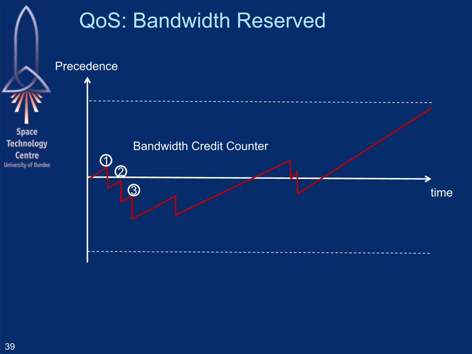
QoS: Bandwidth Reserved
39
time
12
3
Precedence
Bandwidth Credit Counter
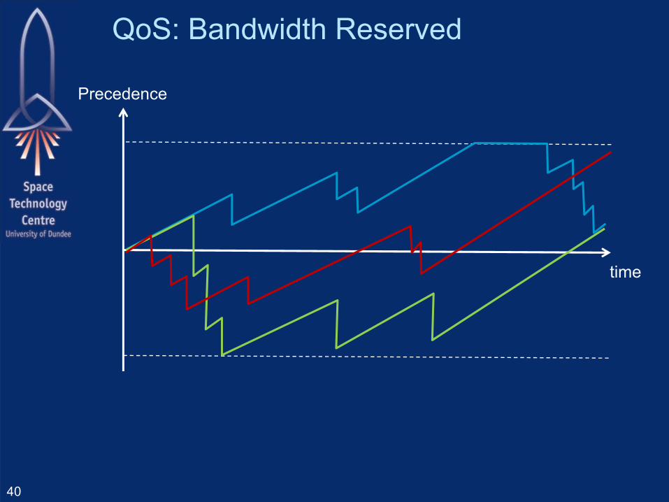
QoS: Bandwidth Reserved
40
time
Precedence

QoS Priority
41
time
Priority 1
Priority 2
Priority 3
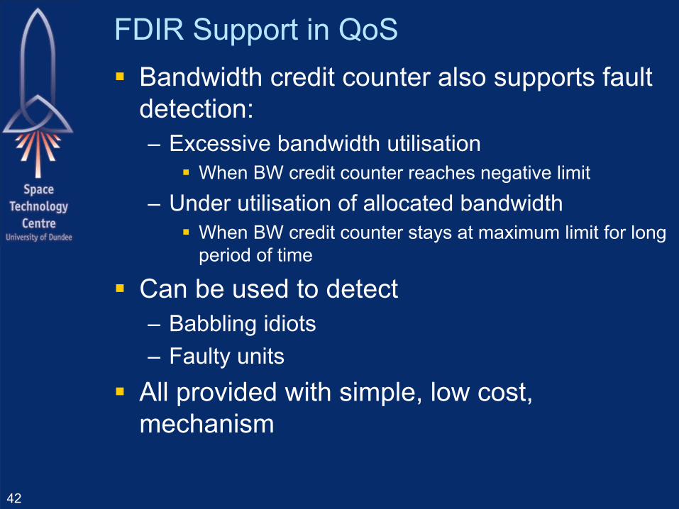
FDIR Support in QoS Bandwidth credit counter also supports fault
detection:– Excessive bandwidth utilisation
When BW credit counter reaches negative limit
– Under utilisation of allocated bandwidth When BW credit counter stays at maximum limit for long
period of time
Can be used to detect– Babbling idiots– Faulty units
All provided with simple, low cost, mechanism
42
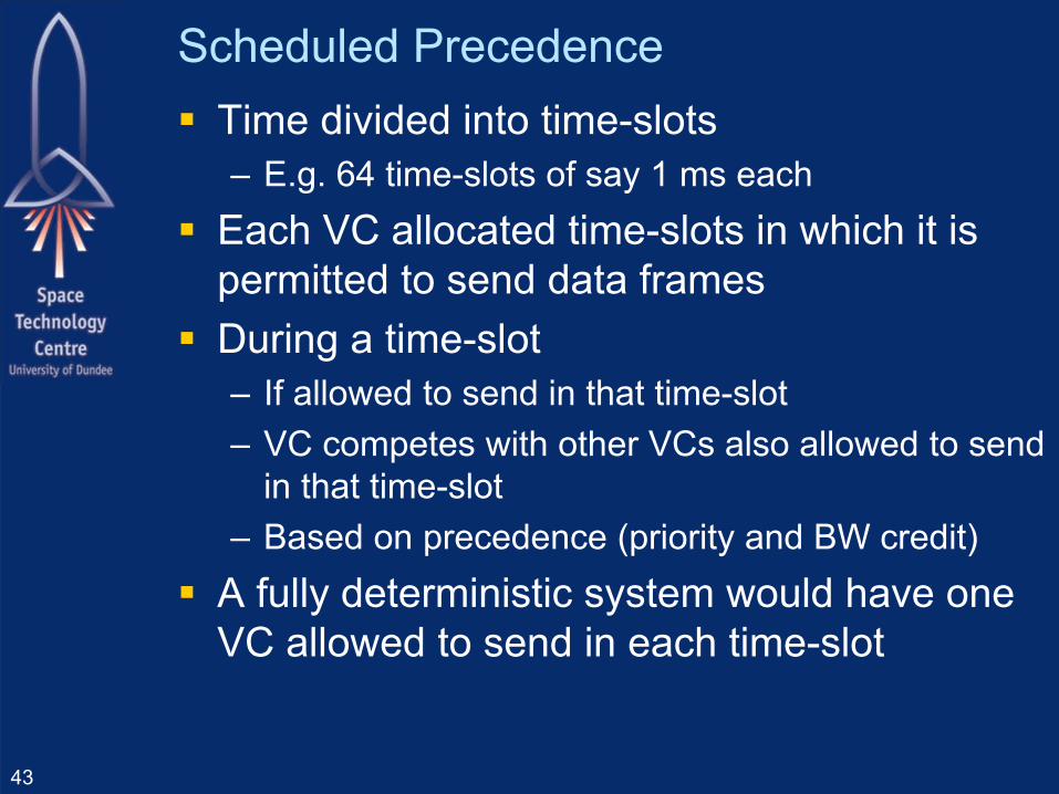
Scheduled Precedence Time divided into time-slots
– E.g. 64 time-slots of say 1 ms each Each VC allocated time-slots in which it is
permitted to send data frames During a time-slot
– If allowed to send in that time-slot– VC competes with other VCs also allowed to send
in that time-slot– Based on precedence (priority and BW credit)
A fully deterministic system would have one VC allowed to send in each time-slot
43
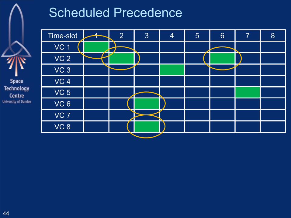
Scheduled Precedence
44
Time-slot 1 2 3 4 5 6 7 8VC 1VC 2VC 3VC 4VC 5VC 6VC 7VC 8
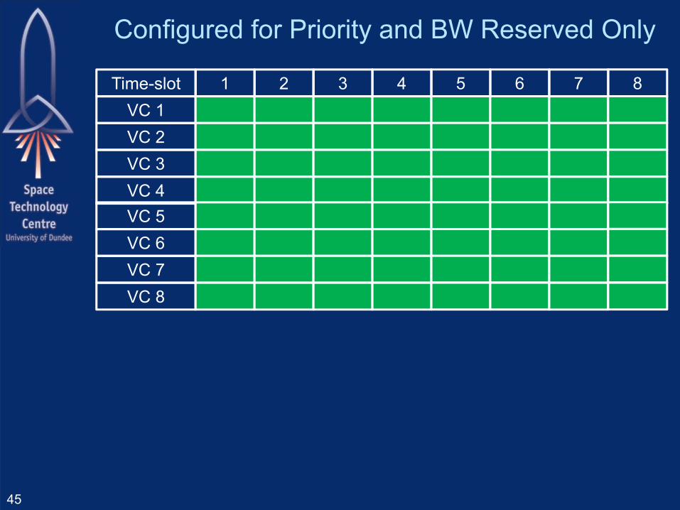
Configured for Priority and BW Reserved Only
45
Time-slot 1 2 3 4 5 6 7 8VC 1VC 2VC 3VC 4VC 5VC 6VC 7VC 8
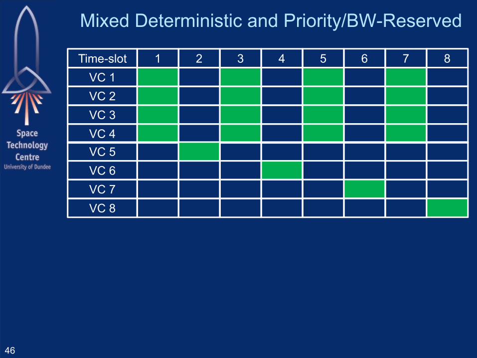
Mixed Deterministic and Priority/BW-Reserved
46
Time-slot 1 2 3 4 5 6 7 8VC 1VC 2VC 3VC 4VC 5VC 6VC 7VC 8

SpaceFibre Update
47
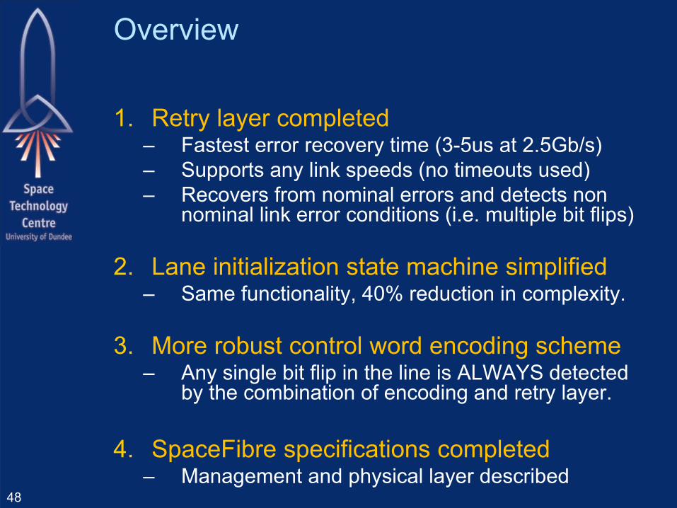
Overview
1. Retry layer completed– Fastest error recovery time (3-5us at 2.5Gb/s) – Supports any link speeds (no timeouts used)– Recovers from nominal errors and detects non
nominal link error conditions (i.e. multiple bit flips)
2. Lane initialization state machine simplified– Same functionality, 40% reduction in complexity.
3. More robust control word encoding scheme– Any single bit flip in the line is ALWAYS detected
by the combination of encoding and retry layer.
4. SpaceFibre specifications completed– Management and physical layer described
48

Retry Layer features
Recovers from an error as fast as possible.– A NACK is sent when any type of error is
detected. 8B10B disparity error CRC error Out of sequence frame (data, idle, FCT..)
– Retry starts as soon as a NACK is received. Current data frame is aborted
– Broadcasts have higher priority than data frames at all times. (i.e. even when an error occurs)
49
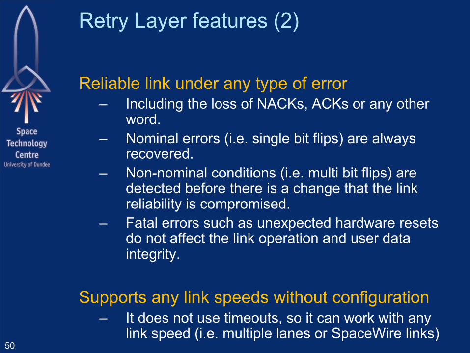
Retry Layer features (2)
Reliable link under any type of error – Including the loss of NACKs, ACKs or any other
word.– Nominal errors (i.e. single bit flips) are always
recovered.– Non-nominal conditions (i.e. multi bit flips) are
detected before there is a change that the link reliability is compromised.
– Fatal errors such as unexpected hardware resets do not affect the link operation and user data integrity.
Supports any link speeds without configuration– It does not use timeouts, so it can work with any
link speed (i.e. multiple lanes or SpaceWire links)50
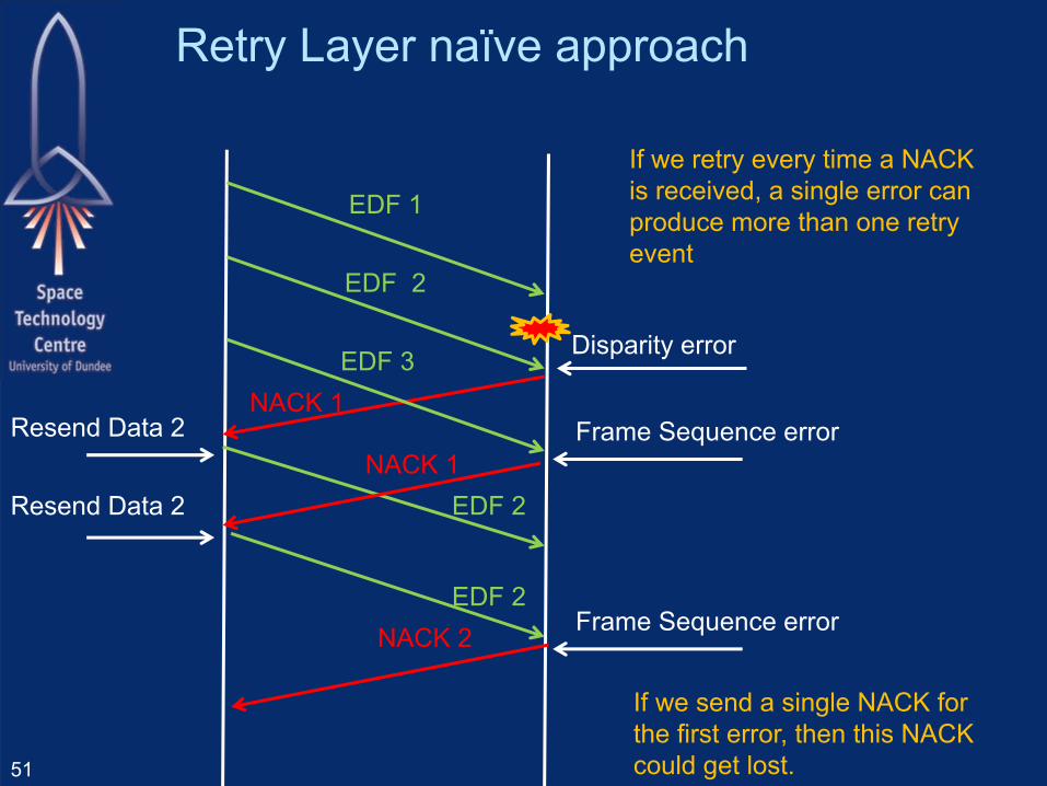
Retry Layer naïve approach
51
EDF 1
NACK 1
EDF 2
EDF 3
EDF 2NACK 1
EDF 2
Resend Data 2
Resend Data 2
If we retry every time a NACK is received, a single error can produce more than one retry event
If we send a single NACK for the first error, then this NACK could get lost.
Disparity error
Frame Sequence error
NACK 2 Frame Sequence error
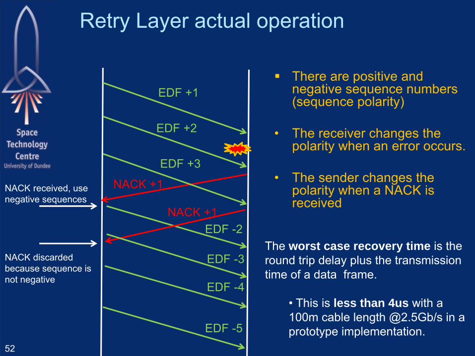
Retry Layer actual operation
52
EDF +1
NACK +1
EDF +2
EDF +3
EDF -2NACK +1
EDF -3
NACK received, use negative sequences
NACK discarded because sequence is not negative
EDF -4
There are positive and negative sequence numbers (sequence polarity)
• The receiver changes the polarity when an error occurs.
• The sender changes the polarity when a NACK is received
EDF -5
The worst case recovery time is the round trip delay plus the transmission time of a data frame.
• This is less than 4us with a 100m cable length @2.5Gb/s in a prototype implementation.
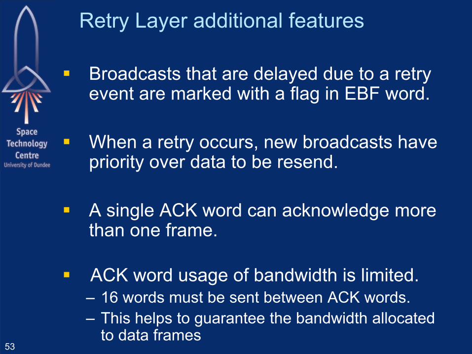
Broadcasts that are delayed due to a retry event are marked with a flag in EBF word.
When a retry occurs, new broadcasts have priority over data to be resend.
A single ACK word can acknowledge more than one frame.
ACK word usage of bandwidth is limited. – 16 words must be sent between ACK words.– This helps to guarantee the bandwidth allocated
to data frames
Retry Layer additional features
53
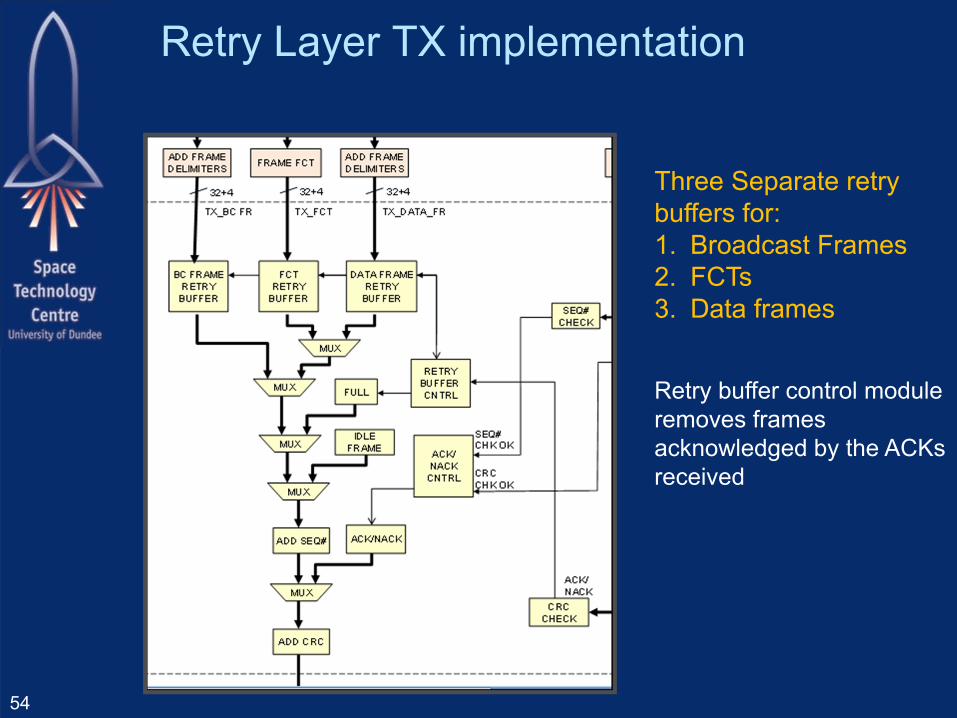
Retry Layer TX implementation
54
Three Separate retry buffers for:1. Broadcast Frames2. FCTs3. Data frames
Retry buffer control module removes frames acknowledged by the ACKs received

The retry buffers holds frames and FCTs until they are acknowledged.
One or more retry buffer can get full if:1. The retry buffer is small and can not hold the amount of data sent
before an ACK is received.2. One or more ACKs are lost due to the cable being disconnected
and connected. We need to request to send a new ACK using the FULL word
Retry buffer full condition
55
Data 1
ACK 1
FULL
- When the retry buffer is full, a FULL word is sent
- When a FULL word is received, and ACK is sent
Data 2
ACK 2
ACK 2
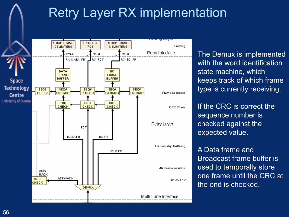
Retry Layer RX implementation
56
The Demux is implemented with the word identification state machine, which keeps track of which frame type is currently receiving.
If the CRC is correct the sequence number is checked against the expected value.
A Data frame and Broadcast frame buffer is used to temporally store one frame until the CRC at the end is checked.
Lane initialization state machine
57
State machine now described using only 11 states instead of the original 19 states.– Error recovery state machine is removed as its
functionality is already covered by the retry layer
Lane is disconnected when the lane receive error counter overflows – This indicates that the BER is too high. – BER is measured by decreasing the error counter every N
words (i.e. leaky bucket algorithm)
Functionality is the same as the previous version.– Supports AutoStart, inverted RX polarity, Standby and
LossOfSignal or receive error overflow indication.
Implementation requires less than half of the original hardware resources.
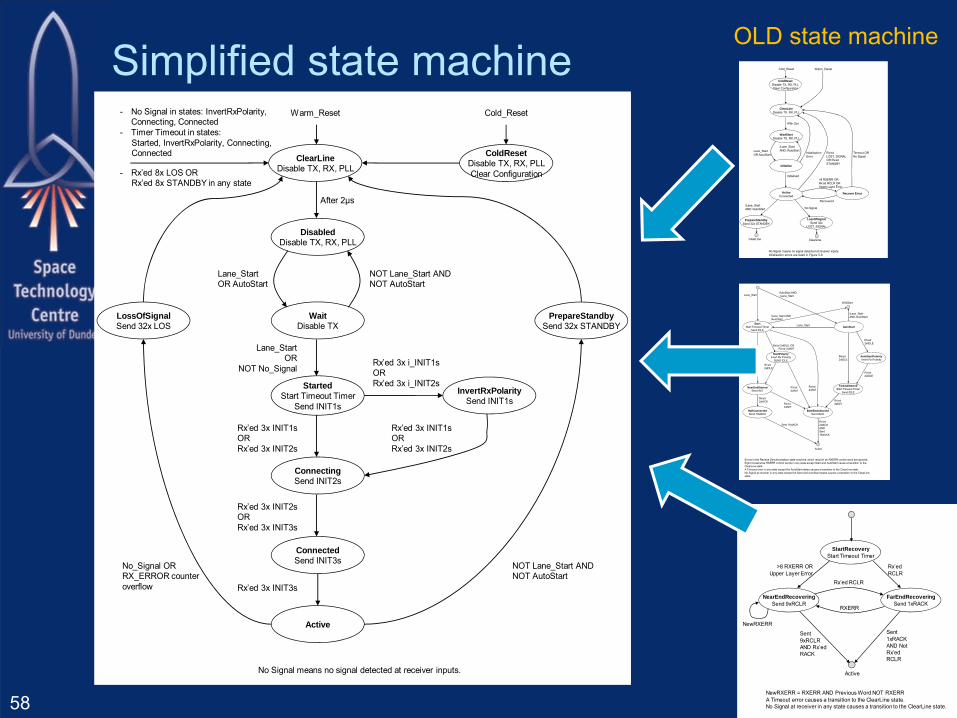
58NewRXERR = RXERR AND Previous Word NOT RXERRA Timeout error causes a transition to the ClearLine state.No Signal at receiver in any state causes a transition to the ClearLine state.
>8 RXERR ORUpper Layer Error
Active
Rx’edRCLR
FarEndRecoveringSend 1xRACK
NearEndRecoveringSend 9xRCLR
Rx’ed RCLR
RXERR
Sent1xRACKAND NotRx’edRCLR
NewRXERR
Sent9xRCLRAND Rx’edRACK
StartRecoveryStart Timeout Timer
AutoStartStart
Start Timeout TimerSend IDLE
AutoStartPolarityInvert Rx Polarity
Rx’ed 2xiIDLE ORRx’ed 2xiINIT
Rx’ed2xINIT
Rx’ed2xiIDLE
Rx’ed2xIDLE
StartPolarityInvert Rx Polarity
SEND IDLE
Lane_Start
FarEndStartedStart Timeout Timer
Send IDLE
Rx’ed2xIDLE
NearEndStartedSend INIT
Errors in the Receive Synchronisation state machine, which result in an RXERR control word are ignored.Eight consecutive RXERR control words in any state except Start and AutoStart cause a transition to the ClearLine state.A Timeout error in any state except the AutoStart states causes a transition to the ClearLine state.No Signal at receiver in any state except the Start and AutoStart states causes a transition to the ClearLine state.
Lane_StartAutoStart AND/Lane_Start
Active
/Lane_Start AND/AutoStart
WaitStart
/Lane_StartAND /AutoStart
BothEndsStartedSend IACK
Rx’ed2xIDLE
Rx’ed2xINIT
Rx’ed2xINIT
Rx’ed2xIDLE
HalfConnectedSend 16xIACK
Rx’ed2xIACK
Sent 16xIACKRx’ed2xIACKANDSent16xIACK
Rx’ed2xINIT
WaitStartDisable TX, RX, PLL
ColdResetDisable TX, RX, PLLClear Configuration
Recover Error
Initialise
Warm_Reset
Initialised
ActiveConnected
PrepareStandbySend 32x STANDBY
LossOfSignalSend 32x
LOST_SIGNAL
No Signal
Cold_Reset
Recovered
ClearLine ClearLine
InitialisationError
ClearLineDisable TX, RX, PLL
After 2μs
Timeout ORNo Signal
>8 RXERR OR Rx’ed RCLR ORUpper Layer Error
No Signal means no signal detected at receiver inputs.Initialisation errors are listed in Figure 5-9.
Rx’edLOST_SIGNALOR Rx’edSTANDBY
Lane_StartOR AutoStart
/Lane_StartAND /AutoStart
/Lane_StartAND /AutoStart
OLD state machine
WaitDisable TX
ClearLineDisable TX, RX, PLL
InvertRxPolaritySend INIT1s
StartedStart Timeout Timer
Send INIT1s
Warm_Reset
ConnectingSend INIT2s
Cold_Reset
DisabledDisable TX, RX, PLL
After 2μs
No Signal means no signal detected at receiver inputs.
Rx’ed 3x INIT1sOR Rx’ed 3x INIT2s
Lane_StartOR AutoStart
NOT Lane_Start ANDNOT AutoStart
ColdResetDisable TX, RX, PLLClear Configuration
Lane_StartOR
NOT No_SignalRx’ed 3x i_INIT1sOR Rx’ed 3x i_INIT2s
Rx’ed 3x INIT1sOR Rx’ed 3x INIT2s
ConnectedSend INIT3s
Rx’ed 3x INIT2sOR Rx’ed 3x INIT3s
Active
Rx’ed 3x INIT3s
PrepareStandbySend 32x STANDBY
LossOfSignalSend 32x LOS
No_Signal ORRX_ERROR counter overflow
NOT Lane_Start ANDNOT AutoStart
- No Signal in states: InvertRxPolarity, Connecting, Connected
- Timer Timeout in states:Started, InvertRxPolarity, Connecting,Connected
- Rx’ed 8x LOS OR Rx’ed 8x STANDBY in any state
Simplified state machine

Typical initialization sequence
1. Disabled– Leave state when lane enabled
2. Wait– Leave state when in Start mode or signal is received.
3. Started– Sends INIT1s to start connection– Leave state when INIT1 or INIT2 received
4. Connecting– Sends INIT2s to indicate that it is receiving words.– Leave state when INIT2 or INIT3 received
5. Connected– Sends INIT3s to exchange connection parameters– Leave state when INIT3 received
6. Active– Sends user data– Leave state when in either end an errors occurs or is
disabled.59
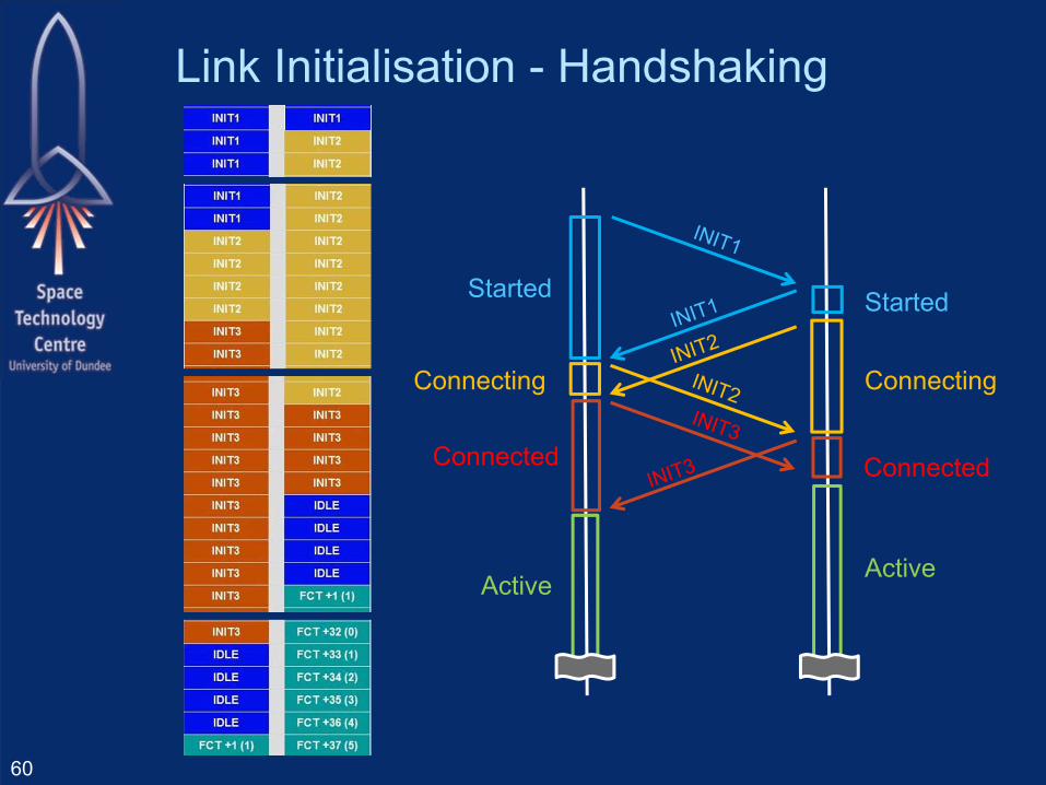
60
Active Active
Started
Connecting
Started
Connecting
Connected Connected
Link Initialisation - Handshaking
Robust control words encoding A control word begins with a comma
– Comma symbol K28.7 is used so that a single bit flip error in a data word can not convert it into a control word.
Second character indicates type of control word. – They are selected to have polarity so any single bit flip
occurred before will produce a 8B10B disparity error.
– They are selected to maximize the hamming distance (number of different bits) between them, so more than three bit flips are required to convert one valid character into another valid one. The hamming distance is 4.
61
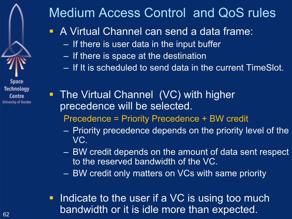
Medium Access Control and QoS rules A Virtual Channel can send a data frame:
– If there is user data in the input buffer– If there is space at the destination– If It is scheduled to send data in the current TimeSlot.
The Virtual Channel (VC) with higher precedence will be selected.Precedence = Priority Precedence + BW credit– Priority precedence depends on the priority level of the
VC.– BW credit depends on the amount of data sent respect
to the reserved bandwidth of the VC.– BW credit only matters on VCs with same priority
Indicate to the user if a VC is using too much bandwidth or it is idle more than expected.62

QoS schemes supported
Deterministic scheduling scheme– All VCs scheduled at different timeslots.
Simple priority scheme– Each VC is set to a different priority levels
Simple Bandwidth allocation– All VCs set to same priority level
Different priorities with bandwidth allocation – Bandwidth arbitration between multiple VCs for payload data– Command and Control set to use higher priority VCs
Different priorities with bandwidth allocation and scheduling– Some slots are reserved for VCs with deterministic
requirements.
63
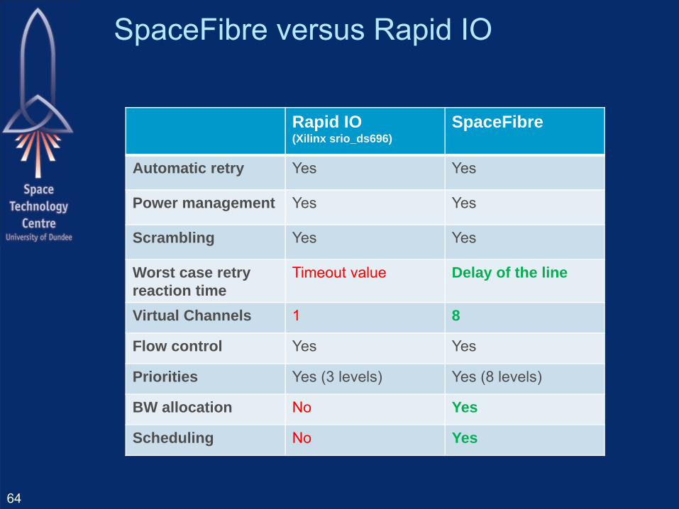
SpaceFibre versus Rapid IO
Rapid IO (Xilinx srio_ds696)
SpaceFibre
Automatic retry Yes Yes
Power management Yes Yes
Scrambling Yes Yes
Worst case retry reaction time
Timeout value Delay of the line
Virtual Channels 1 8
Flow control Yes Yes
Priorities Yes (3 levels) Yes (8 levels)
BW allocation No Yes
Scheduling No Yes
64
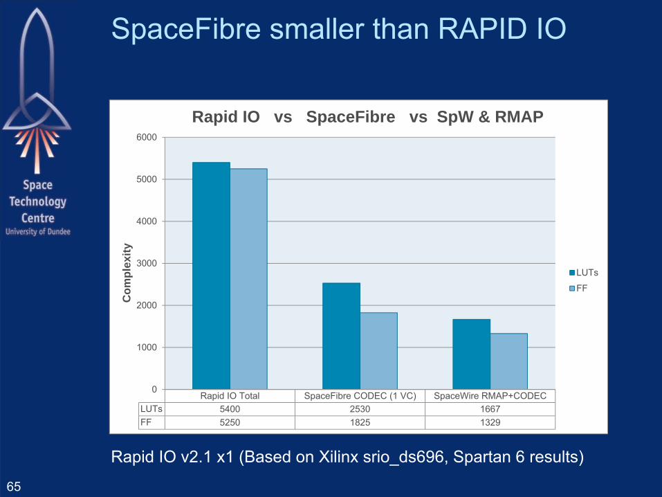
SpaceFibre smaller than RAPID IO
Rapid IO v2.1 x1 (Based on Xilinx srio_ds696, Spartan 6 results)
65
Rapid IO Total SpaceFibre CODEC (1 VC) SpaceWire RMAP+CODECLUTs 5400 2530 1667FF 5250 1825 1329
0
1000
2000
3000
4000
5000
6000C
ompl
exity
Rapid IO vs SpaceFibre vs SpW & RMAP
LUTs
FF

SpaceFibre cost of multiple VCs
66
SpaceFibre CODEC (1 VC) SpaceFibre CODEC (8 VC)LUTs 2530 4850FF 1825 3470
0
1000
2000
3000
4000
5000
6000C
ompl
exity
Complexity: 1 VC vs 8 VC
LUTs
FF

SpaceFibre Next Steps
67

SpaceFibre FDIR FDIR
– Fault detection Parity/disparity Invalid 8B/10B codes Enhance Hamming distance CRC Over and under utilisation of expected bandwidth
– Fault isolation Galvanic isolation Data framing – time containment Virtual channels – bandwidth containment
– Fault recovery Link level retry Graceful degradation on lane failure Babbling idiot protection Error reporting68

SpaceFibre Next Steps Provide TKL2711 interface to CODEC Complete Multi-Lane layer specification Include Multi-Lane layer in CODEC Complete SpaceFibre specification Add Network layer
69