status of the superb collider...
TRANSCRIPT
Status of the SuperB Collider Project
T. Demma, INFN-LNF
on behalf of the SuperB Accelerator Team
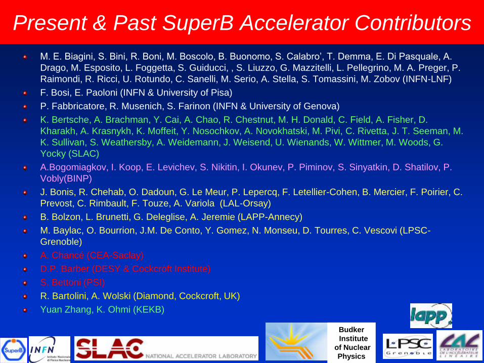
Present & Past SuperB Accelerator Contributors
M. E. Biagini, S. Bini, R. Boni, M. Boscolo, B. Buonomo, S. Calabro’, T. Demma, E. Di Pasquale, A.
Drago, M. Esposito, L. Foggetta, S. Guiducci, , S. Liuzzo, G. Mazzitelli, L. Pellegrino, M. A. Preger, P.
Raimondi, R. Ricci, U. Rotundo, C. Sanelli, M. Serio, A. Stella, S. Tomassini, M. Zobov (INFN-LNF)
F. Bosi, E. Paoloni (INFN & University of Pisa)
P. Fabbricatore, R. Musenich, S. Farinon (INFN & University of Genova)
K. Bertsche, A. Brachman, Y. Cai, A. Chao, R. Chestnut, M. H. Donald, C. Field, A. Fisher, D.
Kharakh, A. Krasnykh, K. Moffeit, Y. Nosochkov, A. Novokhatski, M. Pivi, C. Rivetta, J. T. Seeman, M.
K. Sullivan, S. Weathersby, A. Weidemann, J. Weisend, U. Wienands, W. Wittmer, M. Woods, G.
Yocky (SLAC)
A.Bogomiagkov, I. Koop, E. Levichev, S. Nikitin, I. Okunev, P. Piminov, S. Sinyatkin, D. Shatilov, P.
Vobly(BINP)
J. Bonis, R. Chehab, O. Dadoun, G. Le Meur, P. Lepercq, F. Letellier-Cohen, B. Mercier, F. Poirier, C.
Prevost, C. Rimbault, F. Touze, A. Variola (LAL-Orsay)
B. Bolzon, L. Brunetti, G. Deleglise, A. Jeremie (LAPP-Annecy)
M. Baylac, O. Bourrion, J.M. De Conto, Y. Gomez, N. Monseu, D. Tourres, C. Vescovi (LPSC-
Grenoble)
A. Chancé (CEA-Saclay)
D.P. Barber (DESY & Cockcroft Institute)
S. Bettoni (PSI)
R. Bartolini, A. Wolski (Diamond, Cockcroft, UK)
Yuan Zhang, K. Ohmi (KEKB)
Budker
Institute
of Nuclear
Physics
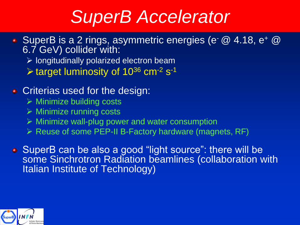
SuperB AcceleratorSuperB is a 2 rings, asymmetric energies (e- @ 4.18, e+ @ 6.7 GeV) collider with: longitudinally polarized electron beam
target luminosity of 1036 cm-2 s-1
Criterias used for the design: Minimize building costs
Minimize running costs
Minimize wall-plug power and water consumption
Reuse of some PEP-II B-Factory hardware (magnets, RF)
SuperB can be also a good “light source”: there will be some Sinchrotron Radiation beamlines (collaboration with Italian Institute of Technology)
4
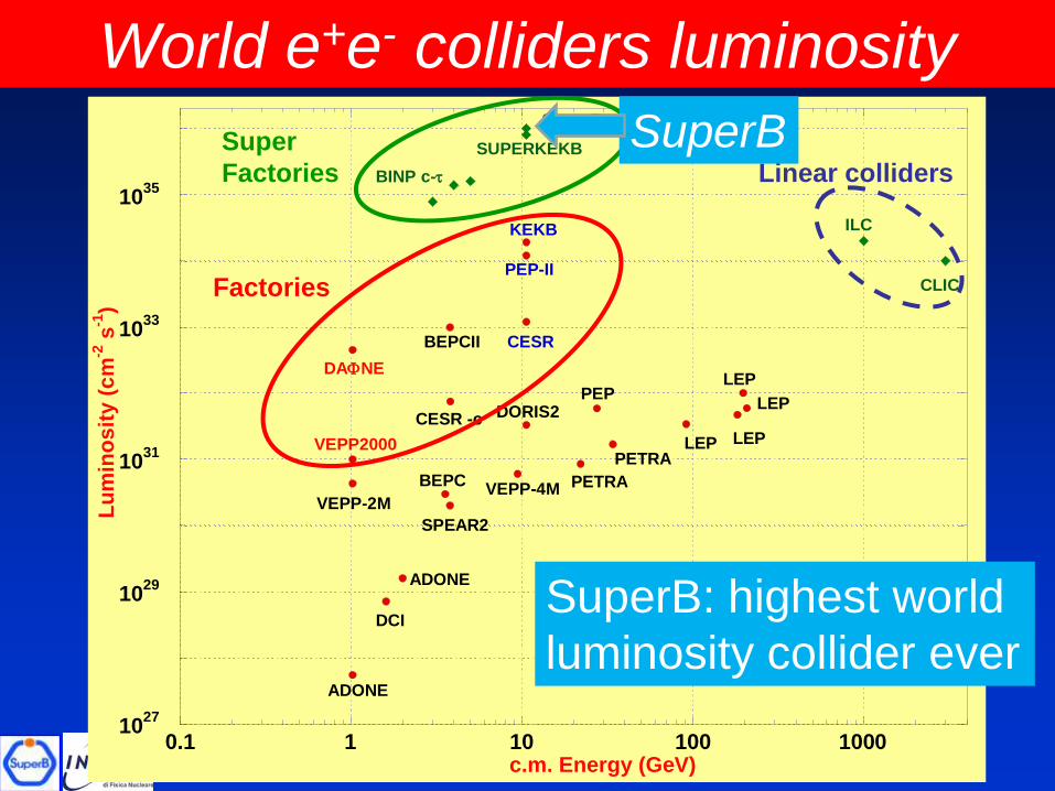
World e+e- colliders luminosity
B-Factories
F-Factories
Future Colliders
1027
1029
1031
1033
1035
0.1 1 10 100 1000
Lu
min
os
ity
(c
m-2
s-1
)
c.m. Energy (GeV)
ADONE
DCI
ADONE
VEPP-2M
VEPP2000
DAFNE
BEPC
SPEAR2
VEPP-4M PETRA
PETRA
PEPDORIS2
BEPCII CESR
PEP-II
KEKB
LEP
LEP
LEP
LEP
ILC
CLIC
SUPERKEKB
SuperB
BINP c-
CESR -c
Super
Factories
Factories
Linear colliders
SuperB
SuperB: highest world
luminosity collider ever
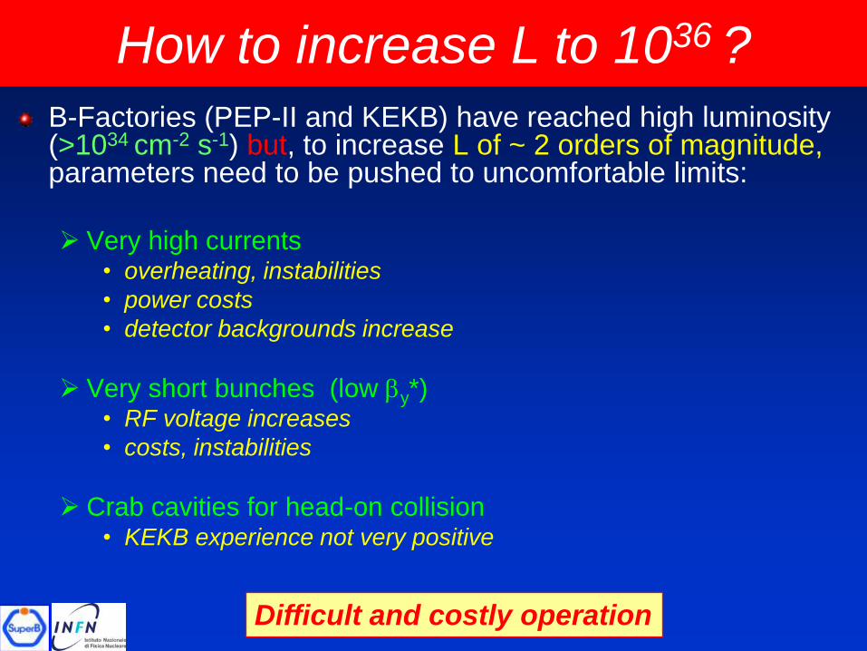
B-Factories (PEP-II and KEKB) have reached high luminosity (>1034 cm-2 s-1) but, to increase L of ~ 2 orders of magnitude,parameters need to be pushed to uncomfortable limits:
Very high currents • overheating, instabilities
• power costs
• detector backgrounds increase
Very short bunches (low by*) • RF voltage increases
• costs, instabilities
Crab cavities for head-on collision• KEKB experience not very positive
How to increase L to 1036 ?
Difficult and costly operation
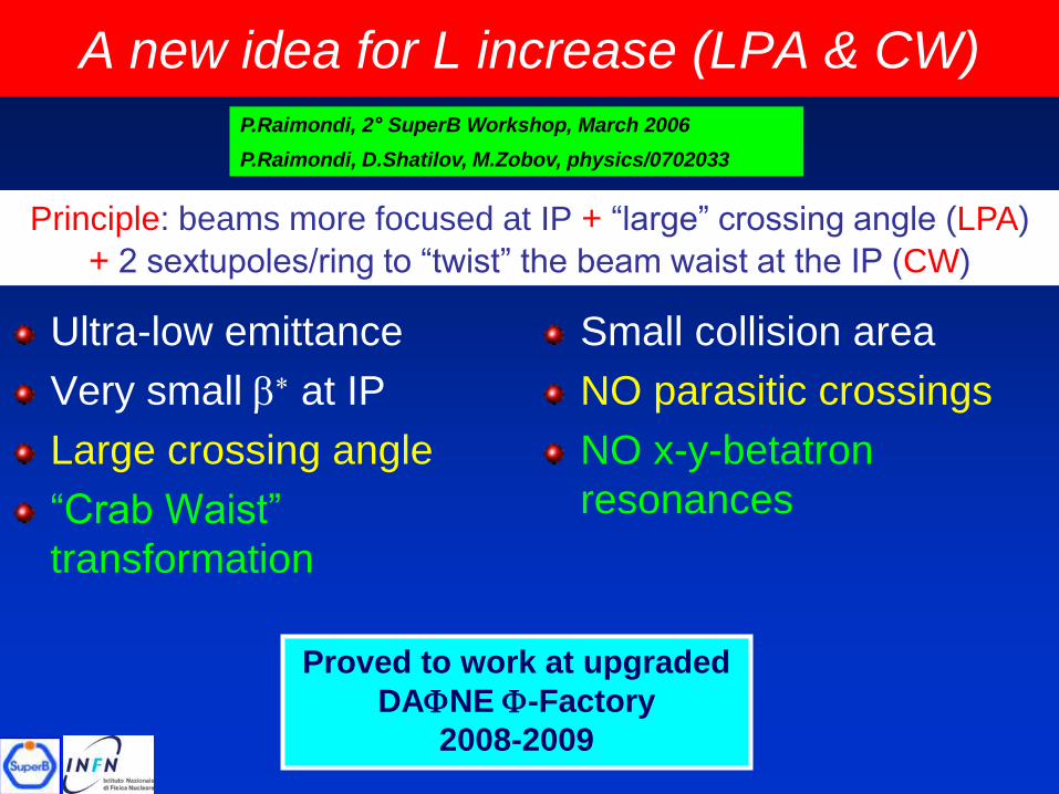
Ultra-low emittance
Very small b* at IP
Large crossing angle
“Crab Waist”
transformation
Small collision area
NO parasitic crossings
NO x-y-betatron
resonances
Principle: beams more focused at IP + “large” crossing angle (LPA)
+ 2 sextupoles/ring to “twist” the beam waist at the IP (CW)
A new idea for L increase (LPA & CW)
Proved to work at upgraded
DAFNE F-Factory
2008-2009
P.Raimondi, 2° SuperB Workshop, March 2006
P.Raimondi, D.Shatilov, M.Zobov, physics/0702033

Large crossing angle, small x-size
(1) and (2) have same
Luminosity, but (2) has
longer bunches and
smaller sx
1) Head-on,
Short bunches
2) Large crossing angle,
long bunches
bY
Overlap region
sz
sxsz
sx
y waist can be moved
along z with a
sextupole
on both sides of IP
at proper phase
“Crab Waist”
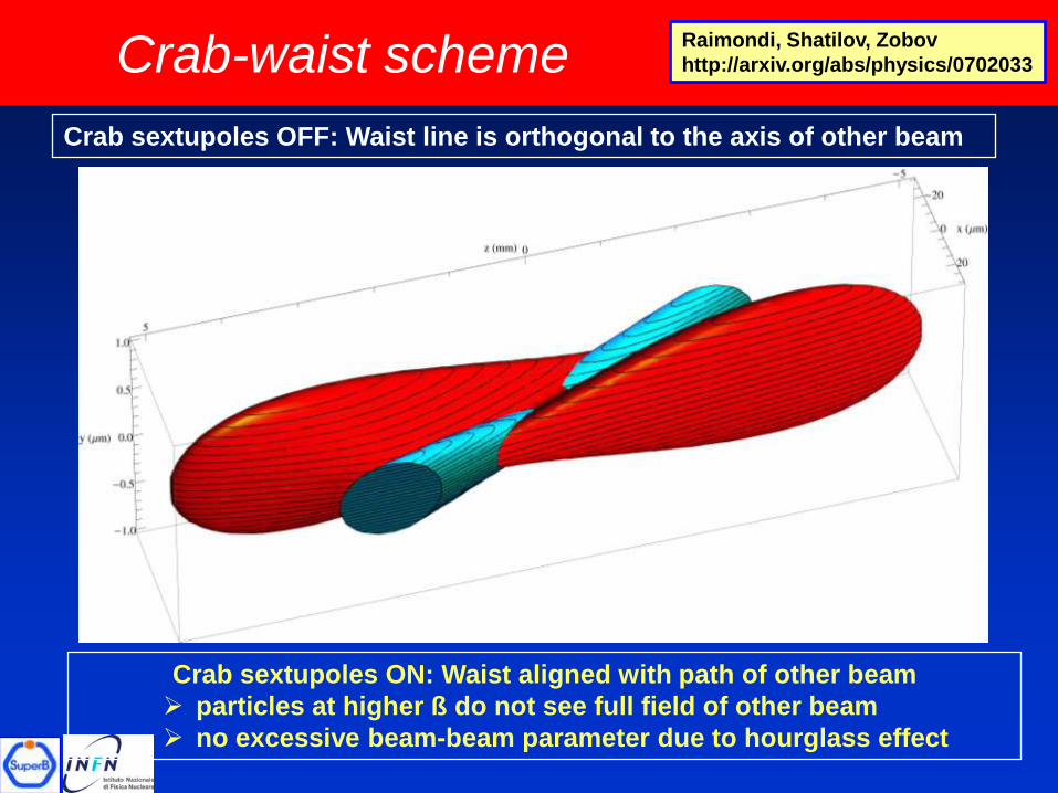
Crab-waist scheme
Crab sextupoles OFF: Waist line is orthogonal to the axis of other beam
Crab sextupoles ON: Waist aligned with path of other beam
particles at higher ß do not see full field of other beam
no excessive beam-beam parameter due to hourglass effect
Raimondi, Shatilov, Zobov
http://arxiv.org/abs/physics/0702033
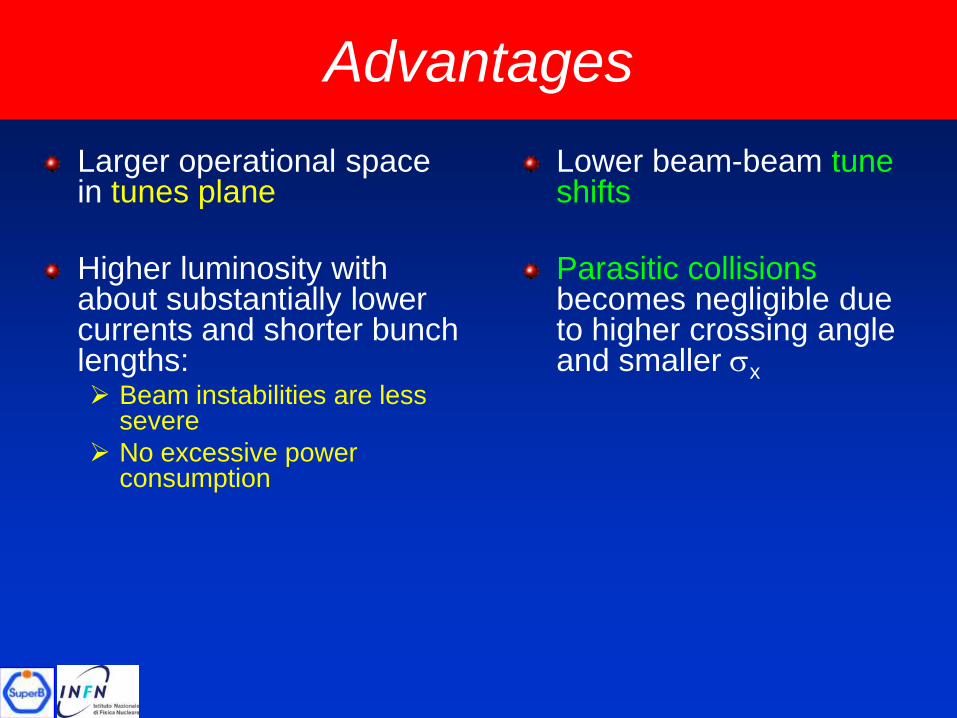
Larger operational space in tunes plane
Higher luminosity with about substantially lower currents and shorter bunch lengths: Beam instabilities are less
severe
No excessive power consumption
Lower beam-beam tune shifts
Parasitic collisionsbecomes negligible due to higher crossing angle and smaller sx
Advantages
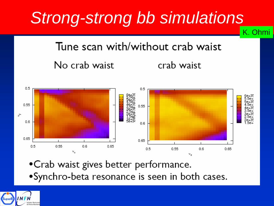
Strong-strong bb simulationsK. Ohmi
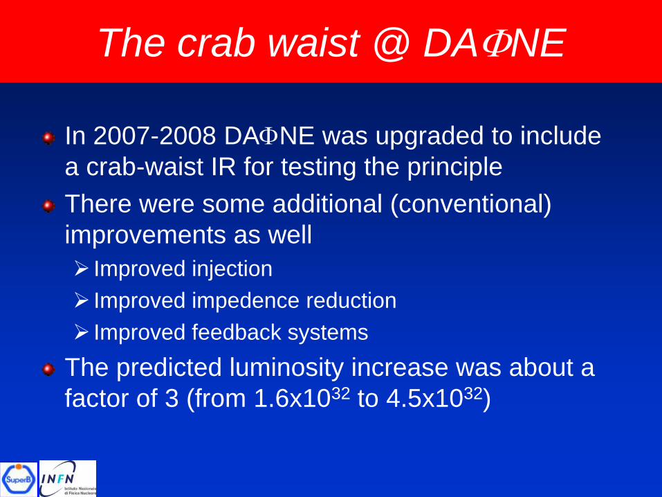
The crab waist @ DAFNE
In 2007-2008 DAFNE was upgraded to include
a crab-waist IR for testing the principle
There were some additional (conventional)
improvements as well
Improved injection
Improved impedence reduction
Improved feedback systems
The predicted luminosity increase was about a
factor of 3 (from 1.6x1032 to 4.5x1032)
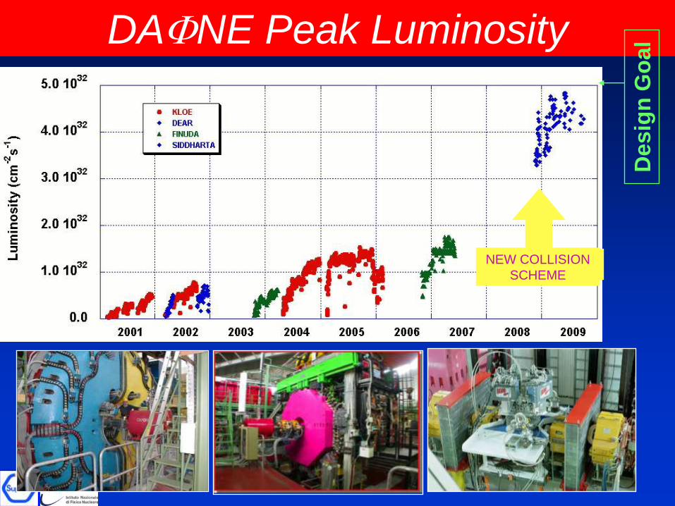
NEW COLLISION
SCHEME
DAFNE Peak Luminosity
Des
ign
Go
al
SuperB design
The design requires state-of-the-art technology for emittance and coupling minimization, vibrations and misalignment control, instabilities control, etc...
SuperB has many similarities with the Damping Rings of ILC and CLIC, and with latest generation SL sources, and can profit from the collaboration among these communities
For details see the new Conceptual Design Report (Dec. 2010) on:
http://arxiv.org/abs/1009.6178v3
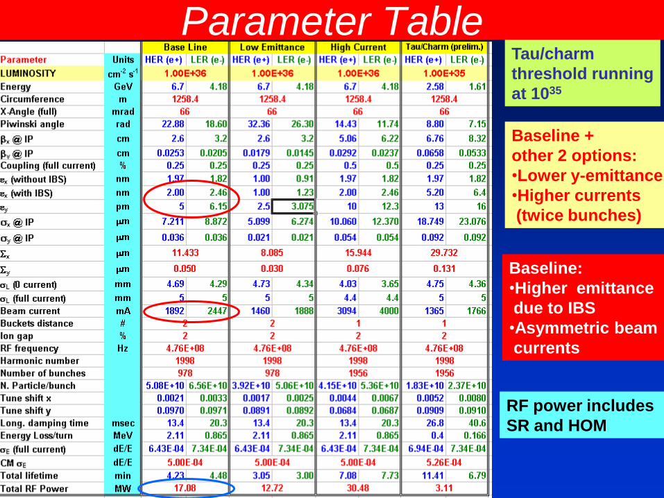
Parameter Table
Baseline +
other 2 options:
•Lower y-emittance
•Higher currents
(twice bunches)
Tau/charm
threshold running
at 1035
Baseline:
•Higher emittance
due to IBS
•Asymmetric beam
currents
RF power includes
SR and HOM
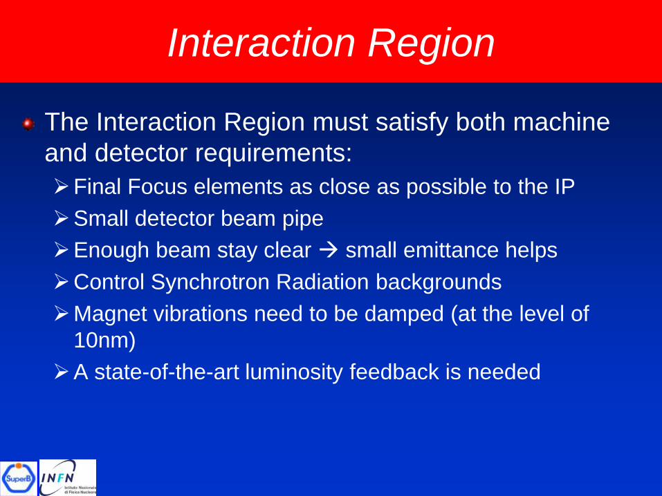
Interaction Region
The Interaction Region must satisfy both machine
and detector requirements:
Final Focus elements as close as possible to the IP
Small detector beam pipe
Enough beam stay clear small emittance helps
Control Synchrotron Radiation backgrounds
Magnet vibrations need to be damped (at the level of
10nm)
A state-of-the-art luminosity feedback is needed
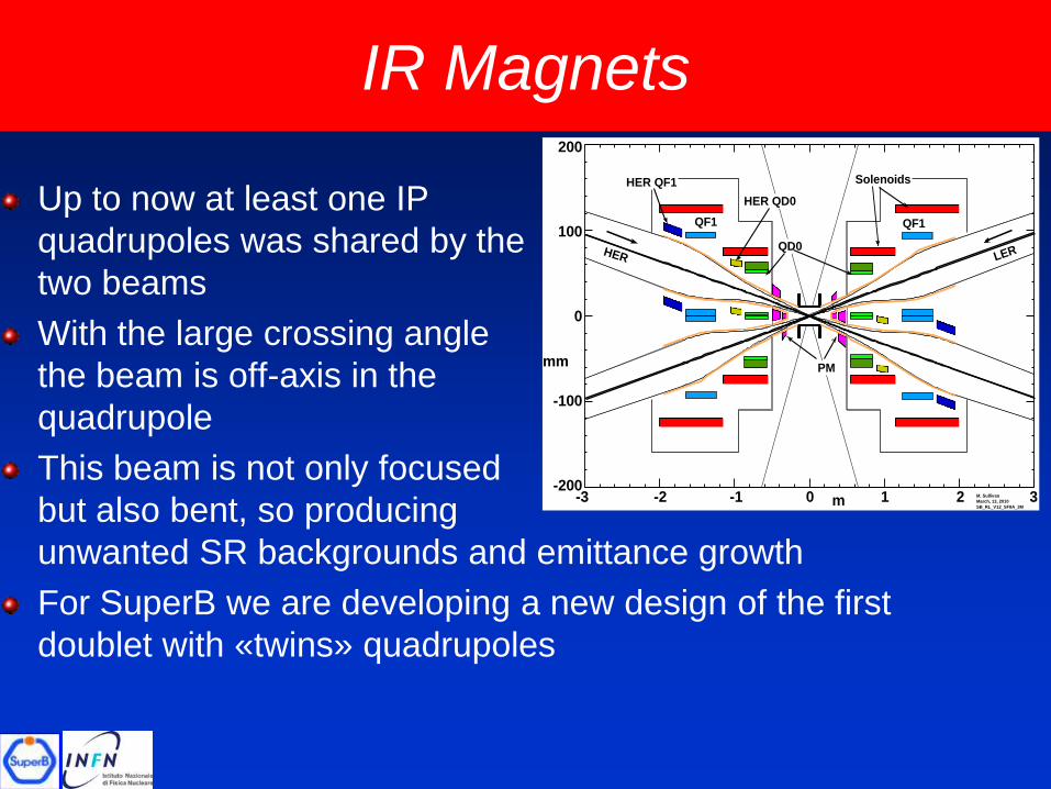
IR Magnets
Up to now at least one IP
quadrupoles was shared by the
two beams
With the large crossing angle
the beam is off-axis in the
quadrupole
This beam is not only focused
but also bent, so producing
unwanted SR backgrounds and emittance growth
For SuperB we are developing a new design of the first
doublet with «twins» quadrupoles
-3 -2 -1 0 1 2 3
0
100
-100
-200
200
mm
mM. Sullivan
March, 13, 2010
SB_RL_V12_SF8A_3M
QF1 QF1
QD0
PM
SolenoidsHER QF1
HER QD0
HER LER
17
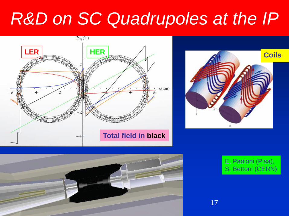
R&D on SC Quadrupoles at the IP
Total field in black
LER HER
E. Paoloni (Pisa),
S. Bettoni (CERN)
Coils
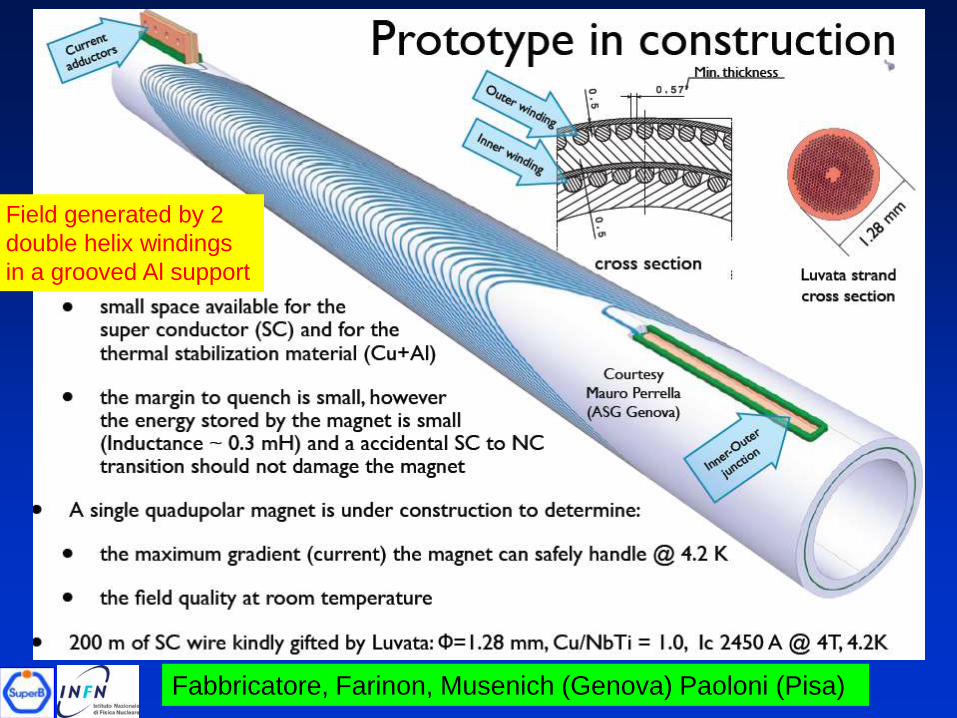
Fabbricatore, Farinon, Musenich (Genova) Paoloni (Pisa)
Field generated by 2
double helix windings
in a grooved Al support
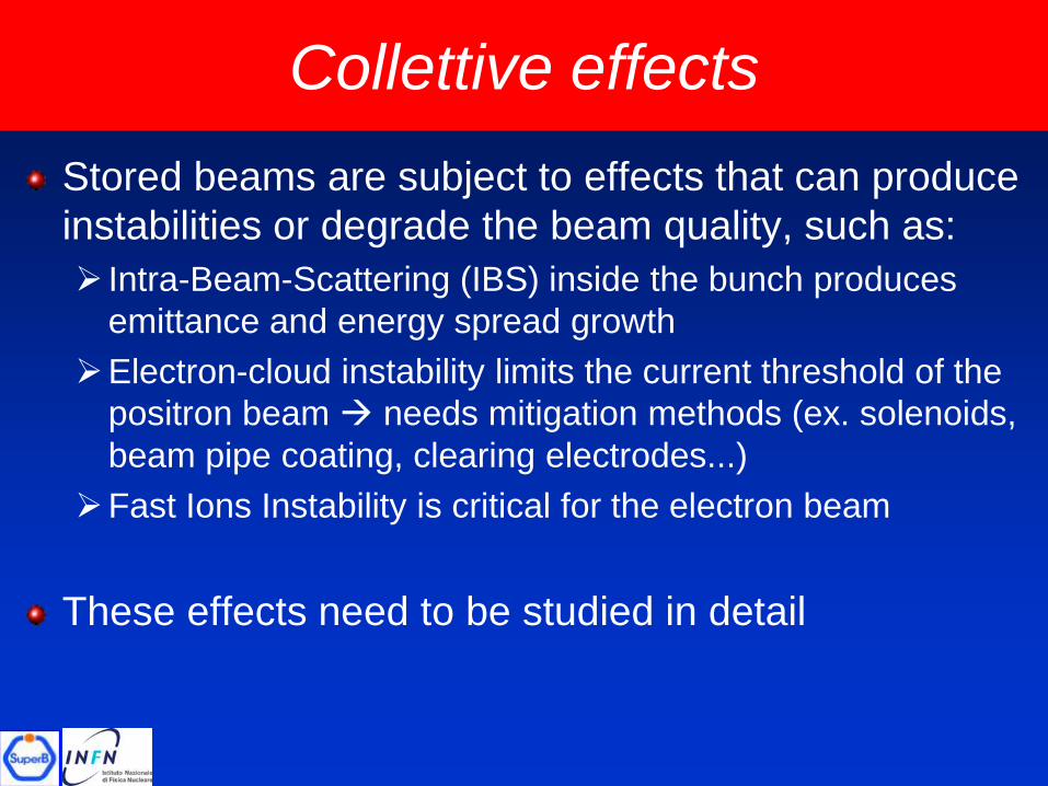
Collettive effects
Stored beams are subject to effects that can produce
instabilities or degrade the beam quality, such as:
Intra-Beam-Scattering (IBS) inside the bunch produces
emittance and energy spread growth
Electron-cloud instability limits the current threshold of the
positron beam needs mitigation methods (ex. solenoids,
beam pipe coating, clearing electrodes...)
Fast Ions Instability is critical for the electron beam
These effects need to be studied in detail
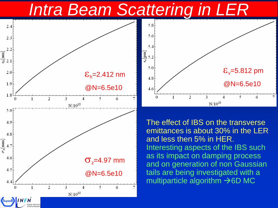
Intra Beam Scattering in LER
The effect of IBS on the transverse emittances is about 30% in the LER and less then 5% in HER.Interesting aspects of the IBS such as its impact on damping process and on generation of non Gaussian tails are being investigated with a multiparticle algorithm 6D MC
h=2.412 nm
@N=6.5e10
v=5.812 pm
@N=6.5e10
sz=4.97 mm
@N=6.5e10
21
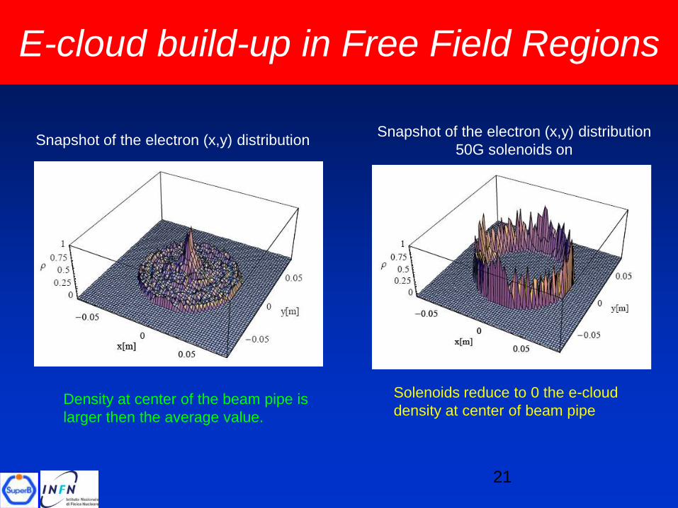
Snapshot of the electron (x,y) distribution
Density at center of the beam pipe is
larger then the average value.
E-cloud build-up in Free Field Regions
Snapshot of the electron (x,y) distribution
50G solenoids on
Solenoids reduce to 0 the e-cloud
density at center of beam pipe
Low emittance tuning
The extremely low design beam emittance needs to
be tuned and minimized careful correction of the
magnet alignment and field errors
These errors produce emittance coupling with transfer
of some horizontal emittance to the vertical plane
this needs to be minimized
Beta-beating (ring b-functions are not as in the model
machine, but are perturbed by the magnet errors) also
needs minimization
Vertical dispersion at IP needs to be corrected to the
lowest possible value not to compromise luminosity
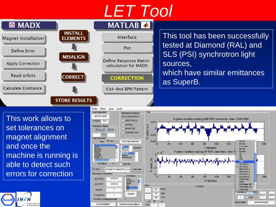
LET Tool
This tool has been successfully
tested at Diamond (RAL) and
SLS (PSI) synchrotron light
sources,
which have similar emittances
as SuperB.
This work allows to
set tolerances on
magnet alignment
and once the
machine is running is
able to detect such
errors for correction
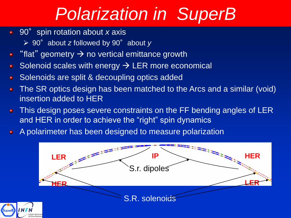
Polarization in SuperB 90°spin rotation about x axis
90°about z followed by 90°about y
“flat” geometry no vertical emittance growth
Solenoid scales with energy LER more economical
Solenoids are split & decoupling optics added
The SR optics design has been matched to the Arcs and a similar (void)
insertion added to HER
This design poses severe constraints on the FF bending angles of LER
and HER in order to achieve the “right” spin dynamics
A polarimeter has been designed to measure polarization
IP HER
HER LER
LER
S.R. solenoids
S.r. dipoles
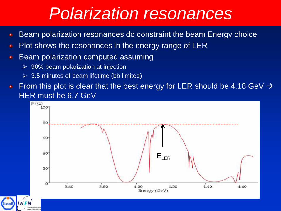
Polarization resonances
ELER
Beam polarization resonances do constraint the beam Energy choice
Plot shows the resonances in the energy range of LER
Beam polarization computed assuming
90% beam polarization at injection
3.5 minutes of beam lifetime (bb limited)
From this plot is clear that the best energy for LER should be 4.18 GeV
HER must be 6.7 GeV
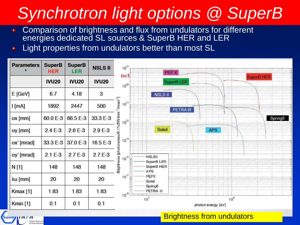
Synchrotron light options @ SuperBComparison of brightness and flux from undulators for different energies dedicated SL sources & SuperB HER and LER
Light properties from undulators better than most SL
Brightness from undulators
SuperB layout
Site chosen @ Tor Vergata University (Rome II) campus
Sinchrotron Light (SL) beamlines are becomingpart of the layout (HER preferred at the moment)
One tunnel will host both rings, which will probablyhave a tilt one respect to the other, to allow for easier crossing and SL beamlines from both HER and LER (if needed)
The position of the Linac complex has still to be finalized, depending on the injection requirements
The rings layout has been recently improved to accomodate Insertion Devices (ID) needed for SL users
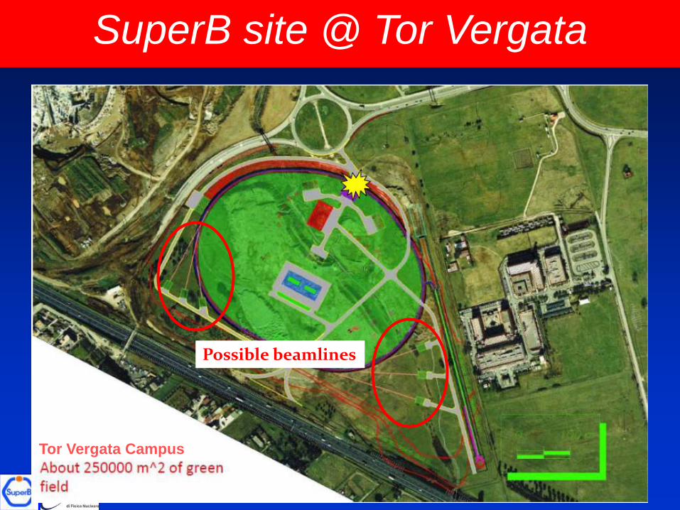
Tor Vergata Campus
Possible beamlines
SuperB site @ Tor Vergata
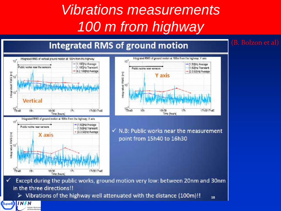
Vibrations measurements
100 m from highway(B. Bolzon et al)
Conclusions
LPA & CW scheme is promising to push forward
the high luminosity frontier for storage rings
colliders (tests on adapting an existing machine,
DAFNE, have been very successfull)
SuperB parameters are being optimized around
1x1036 cm-2 s-1
R&D activities are ongoing in cooperation with
many laboratories/Institutions, taking into account
their expertise in the field.
A first contact with IIT has been established to
explore the needs for the SL users
SPARE SLIDES
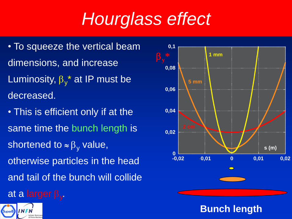
Hourglass effect
• To squeeze the vertical beam
dimensions, and increase
Luminosity, by* at IP must be
decreased.
• This is efficient only if at the
same time the bunch length is
shortened to by value,
otherwise particles in the head
and tail of the bunch will collide
at a larger by.
Bunch length
by*
0
0,02
0,04
0,06
0,08
0,1
-0,02 -0,01 0 0,01 0,02
s (m)
1 mm
5 mm
2 cm
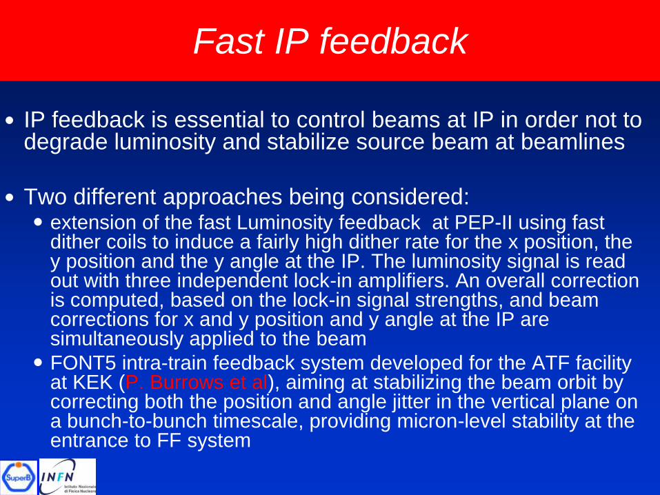
Fast IP feedback
IP feedback is essential to control beams at IP in order not to degrade luminosity and stabilize source beam at beamlines
Two different approaches being considered: extension of the fast Luminosity feedback at PEP-II using fast
dither coils to induce a fairly high dither rate for the x position, the y position and the y angle at the IP. The luminosity signal is read out with three independent lock-in amplifiers. An overall correction is computed, based on the lock-in signal strengths, and beam corrections for x and y position and y angle at the IP are simultaneously applied to the beam
FONT5 intra-train feedback system developed for the ATF facility at KEK (P. Burrows et al), aiming at stabilizing the beam orbit by correcting both the position and angle jitter in the vertical plane on a bunch-to-bunch timescale, providing micron-level stability at the entrance to FF system
Page 34
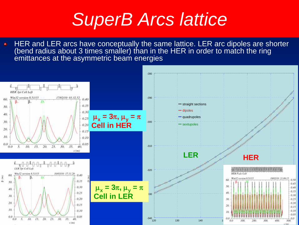
SuperB Arcs lattice
-340
-330
-320
-310
-300
-290
-280
120 130 140 150 160 170 180
-- straight sections
-- dipoles
-- quadrupoles
-- sextupoles
LER HER
HER and LER arcs have conceptually the same lattice. LER arc dipoles are shorter (bend radius about 3 times smaller) than in the HER in order to match the ring emittances at the asymmetric beam energies
mx = 3p, my = p
Cell in HER
mx = 3p, my = p
Cell in LER
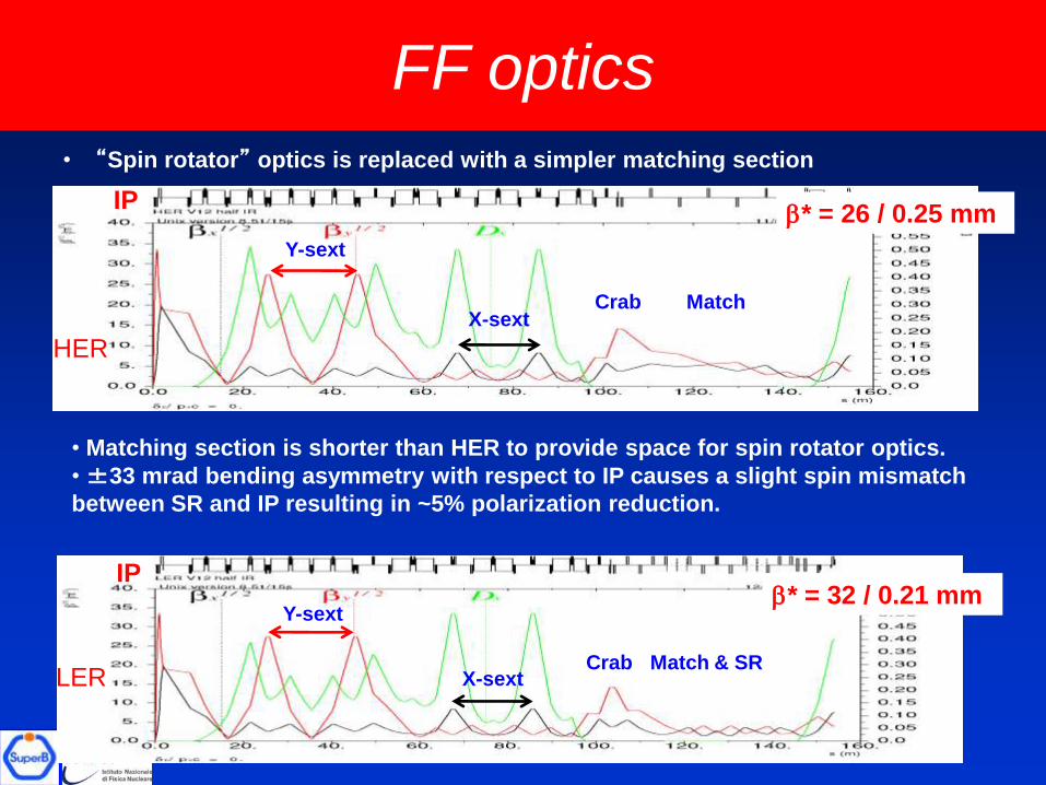
FF optics
• “Spin rotator” optics is replaced with a simpler matching section
IP
Y-sext
X-sextMatchCrab
HER
• Matching section is shorter than HER to provide space for spin rotator optics.
•±33 mrad bending asymmetry with respect to IP causes a slight spin mismatch
between SR and IP resulting in ~5% polarization reduction.
IP
Y-sext
X-sextMatch & SRCrab
LER
b* = 26 / 0.25 mm
b* = 32 / 0.21 mm
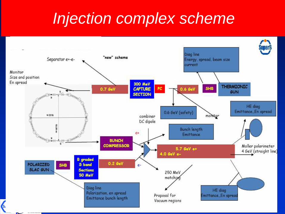
Injection complex scheme
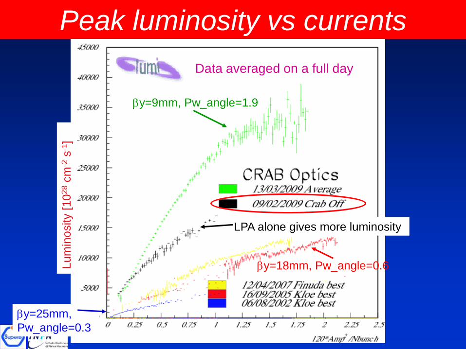
Peak luminosity vs currents
Lum
inosity [
10
28
cm
-2s
-1]
by=18mm, Pw_angle=0.6
by=9mm, Pw_angle=1.9
LPA alone gives more luminosity
Data averaged on a full day
by=25mm,
Pw_angle=0.3