static force analysis
TRANSCRIPT
Theory of Machines
LECTURE NOTES- MECE 303 Theory of
Machines
9- Static Force Analysis
Fall Semester 2010/2011
Halil Orhan YILDIRAN, MS
1
Static Force Analysis
.
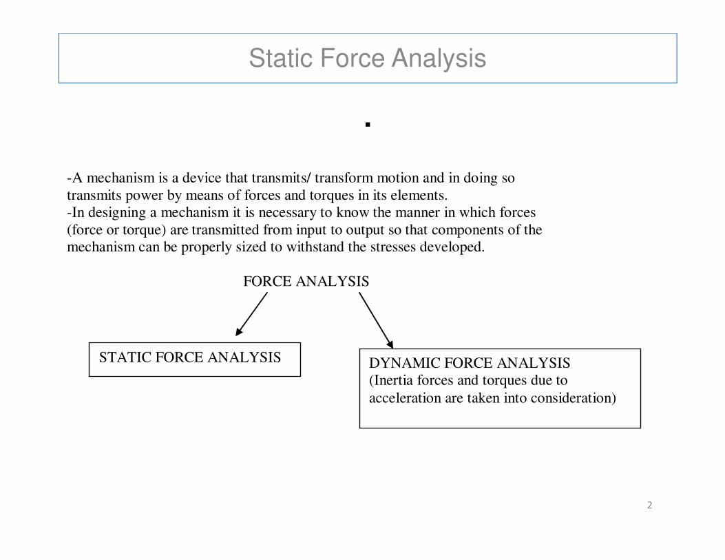
-A mechanism is a device that transmits/ transform motion and in doing so transmits power by means of forces and torques in its elements. -In designing a mechanism it is necessary to know the manner in which forces (force or torque) are transmitted from input to output so that components of the mechanism can be properly sized to withstand the stresses developed.
FORCE ANALYSIS
2
FORCE ANALYSIS
DYNAMIC FORCE ANALYSIS (Inertia forces and torques due to acceleration are taken into consideration)
STATIC FORCE ANALYSIS
Static Force Analysis
Consider a planar (2D) mechanism:
-Given input motion (displacements, velocities and accelerations)
-Find:
*Motion of the rest of the mechanism
* The forces necessary to generate the motion of the mechanism ,
(# independent forces required to generate the motion of the (# independent forces required to generate the motion of the
mechanism is equal to the dof of that mechanism)
* Joint (reaction) forces
ASSUMPTIONS
-Rigid body assumptions of the components are used
-Gravity may or may not be considered
-Frictional forces at the joints will be assumed to be negligible3
Static Force Analysis
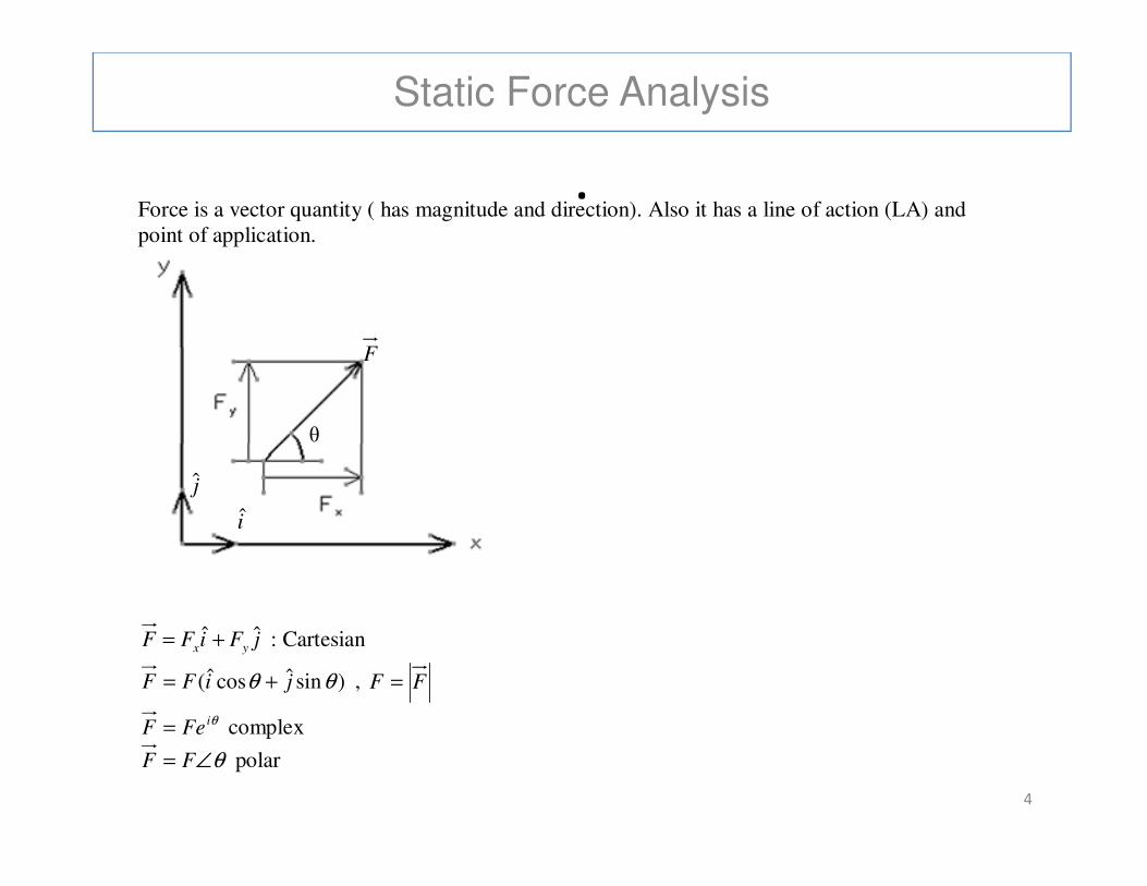
.Force is a vector quantity ( has magnitude and direction). Also it has a line of action (LA) and point of application.
θ
F
4
jFiFF yxˆˆ += : Cartesian
)sinˆcosˆ( θθ jiFF += , FF =
θiFeF = complex
θ∠= FF polar
θ
i
j
Static Force Analysis
.
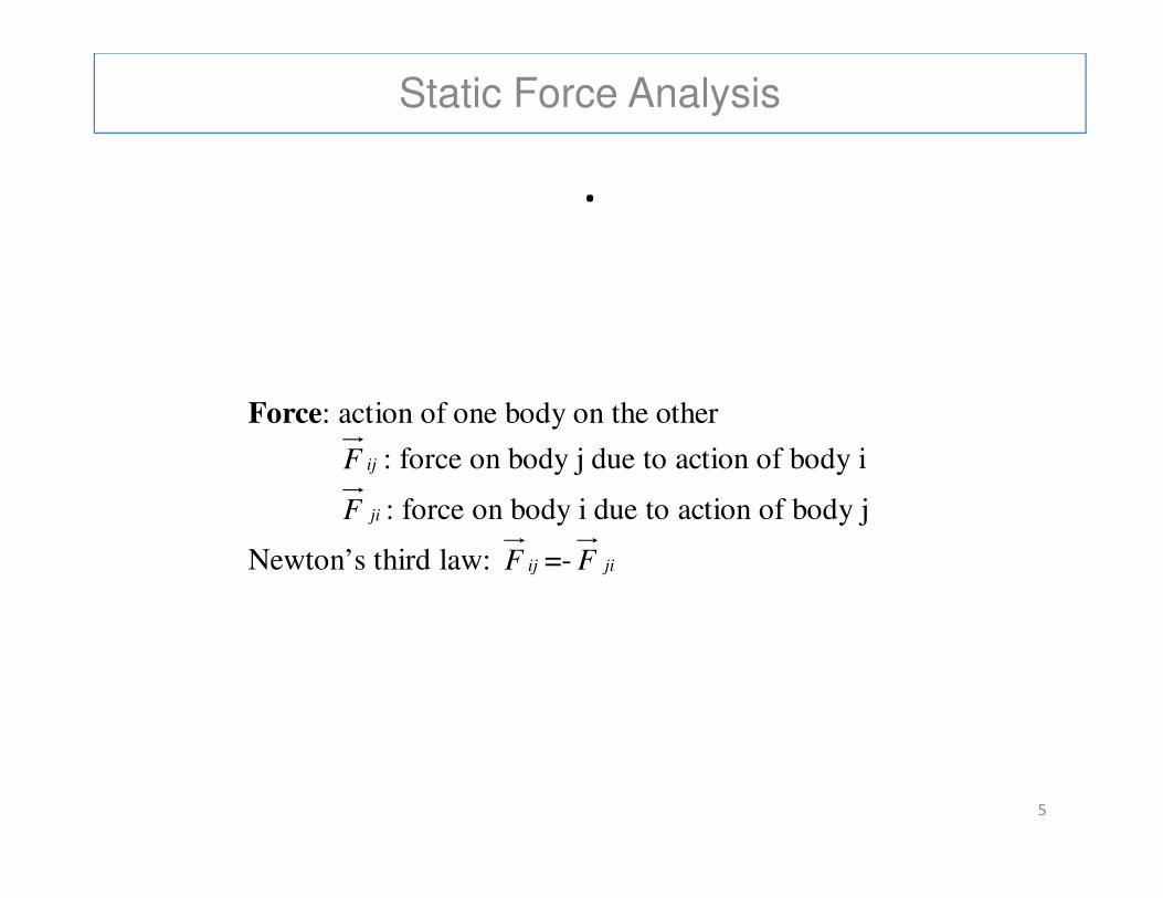
Force: action of one body on the other
F : force on body j due to action of body i
5
ijF : force on body j due to action of body i
jiF : force on body i due to action of body j
Newton’s third law: ijF =- jiF

Static Force Analysis
In order to calculate forces and torques in a mechanism, it is
necessary to isolate each element of the mechanism as a free
body (which is called Free Body Diagram -FBD) and then apply
equilibrium conditions.
'
1iF
'
1iF
6
FBD of link i
kiF
1iF
"
1iF
jiM
jiF
"
1iF
Static Force Analysis
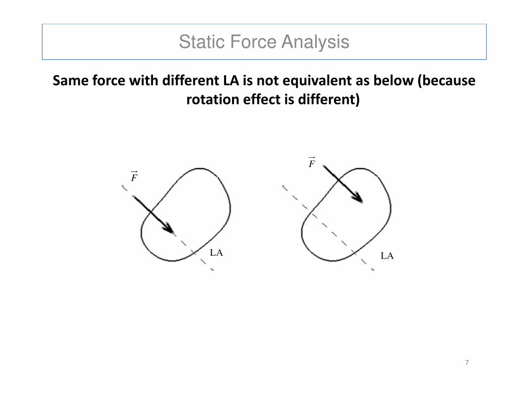
Same force with different LA is not equivalent as below (because
rotation effect is different)
F
F
7
LA LA
Static Force Analysis
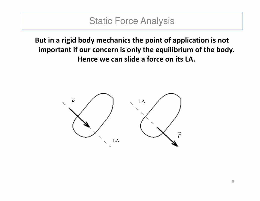
But in a rigid body mechanics the point of application is not
important if our concern is only the equilibrium of the body.
Hence we can slide a force on its LA.
F LA
8
F
LA F
LA
Static Force Analysis
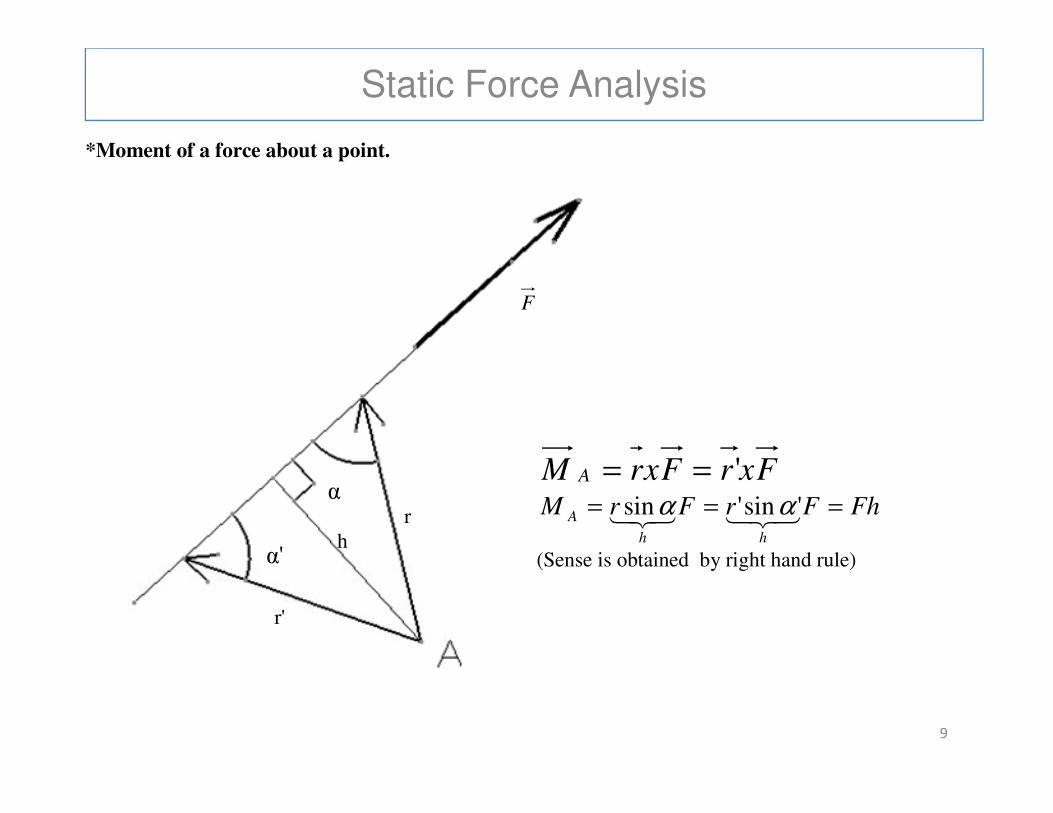
.*Moment of a force about a point.
F
9
FxrFxrM A '==
FhFrFrMhh
A === 321321 'sin'sin αα
(Sense is obtained by right hand rule)
r'
r h
α'
α
Static Force Analysis
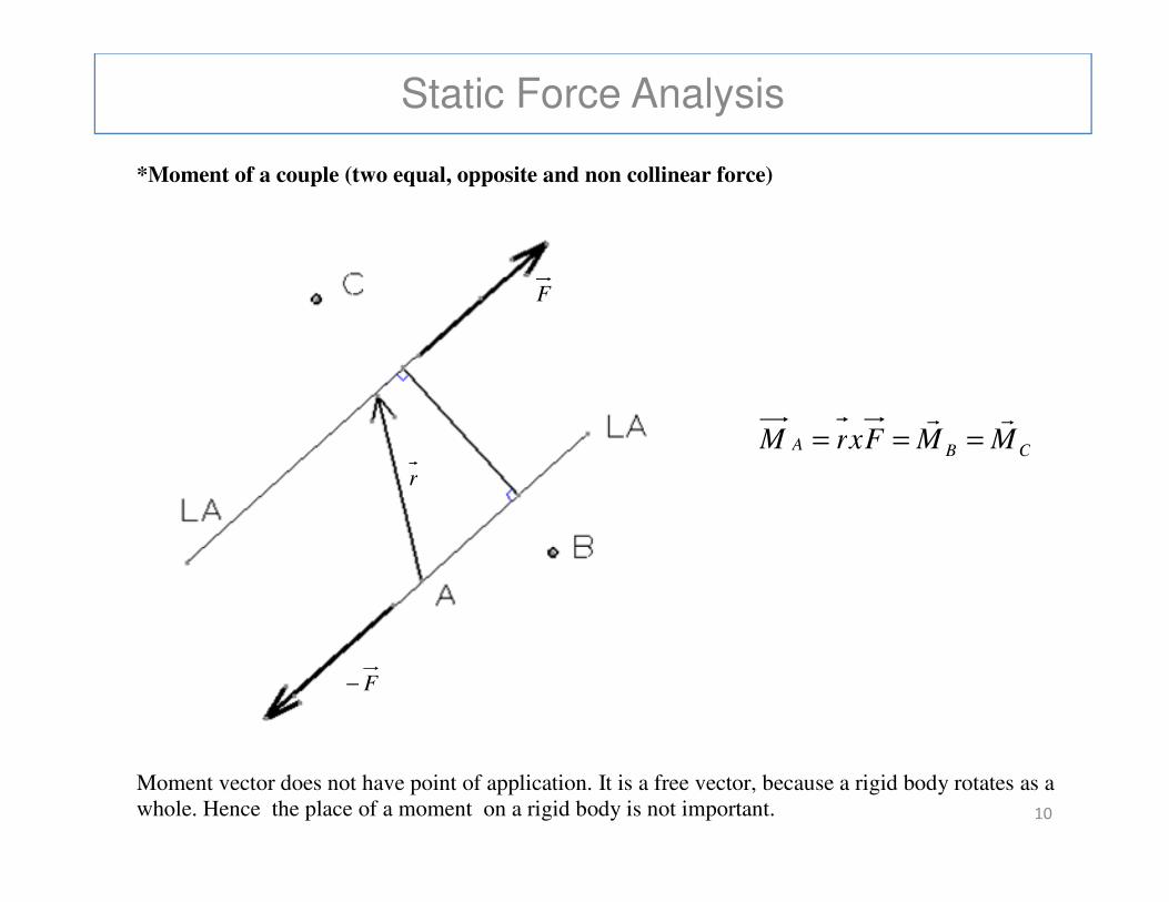
.*Moment of a couple (two equal, opposite and non collinear force)
F
CBA MMFxrMrr
===
10
Moment vector does not have point of application. It is a free vector, because a rigid body rotates as a whole. Hence the place of a moment on a rigid body is not important.
F−
r
CBA MMFxrM ===
Static Force Analysis
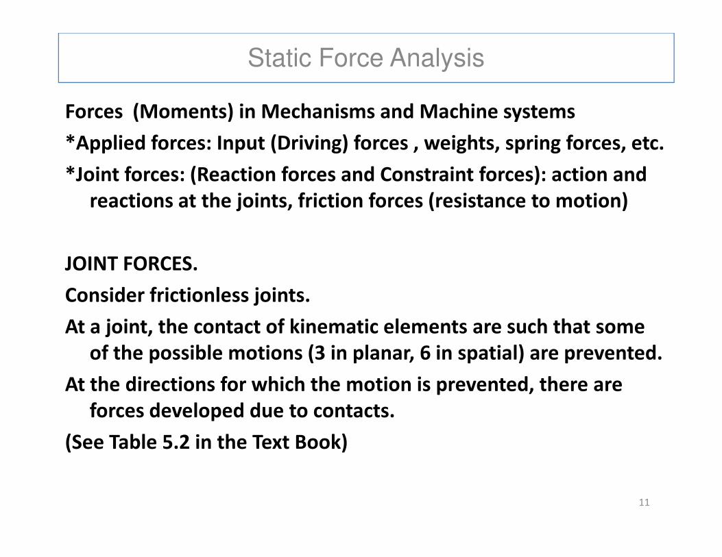
Forces (Moments) in Mechanisms and Machine systems
*Applied forces: Input (Driving) forces , weights, spring forces, etc.
*Joint forces: (Reaction forces and Constraint forces): action and
reactions at the joints, friction forces (resistance to motion)
JOINT FORCES.
Consider frictionless joints.
At a joint, the contact of kinematic elements are such that some
of the possible motions (3 in planar, 6 in spatial) are prevented.
At the directions for which the motion is prevented, there are
forces developed due to contacts.
(See Table 5.2 in the Text Book)
11
Static Force Analysis
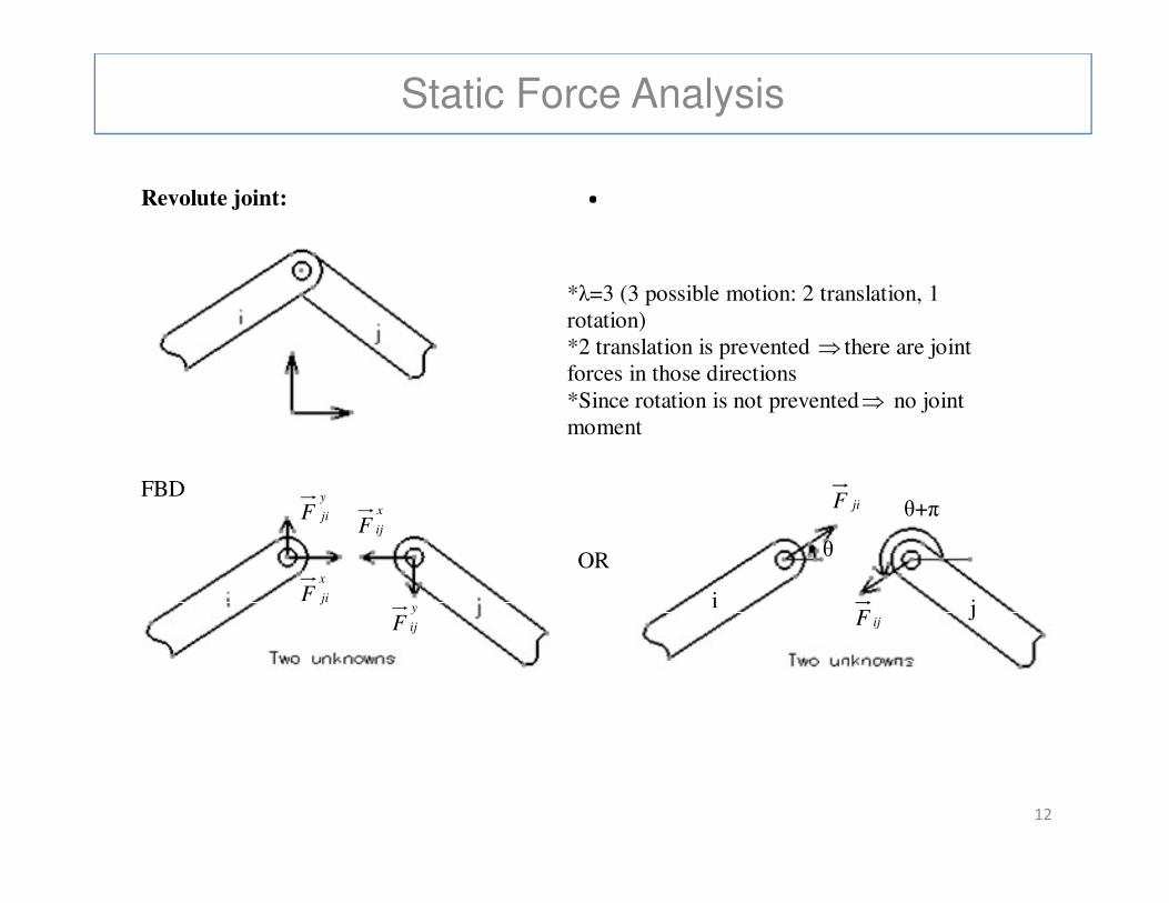
.Revolute joint:
*λ=3 (3 possible motion: 2 translation, 1 rotation) *2 translation is prevented ⇒ there are joint forces in those directions *Since rotation is not prevented⇒ no joint moment
12
FBD
jiF
ijF
θ
θ+π
OR x
jiF
x
ijF
y
jiF
y
ijFi j
Static Force Analysis
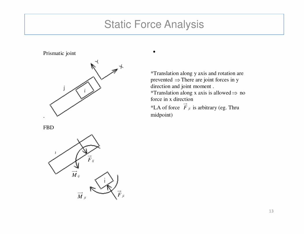
.Prismatic joint
*Translation along y axis and rotation are prevented ⇒There are joint forces in y direction and joint moment . *Translation along x axis is allowed⇒ no force in x direction
*LA of force jiF is arbitrary (eg. Thru
midpoint)
13
FBD
midpoint)
ijF
jiFjiM
ijM
Static Force Analysis
.
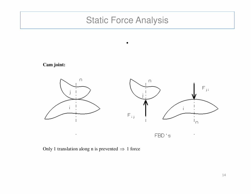
Cam joint:
14
Only 1 translation along n is prevented ⇒ 1 force
Static Force Analysis
.
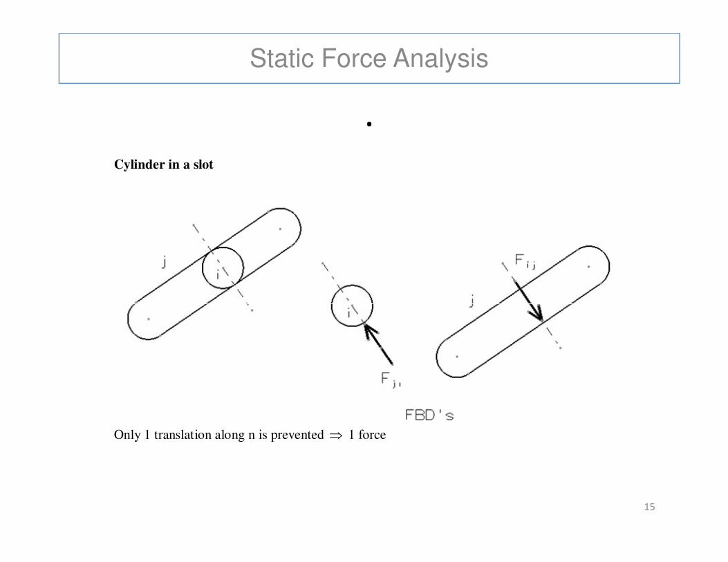
Cylinder in a slot
15
Only 1 translation along n is prevented ⇒ 1 force
Static Force Analysis
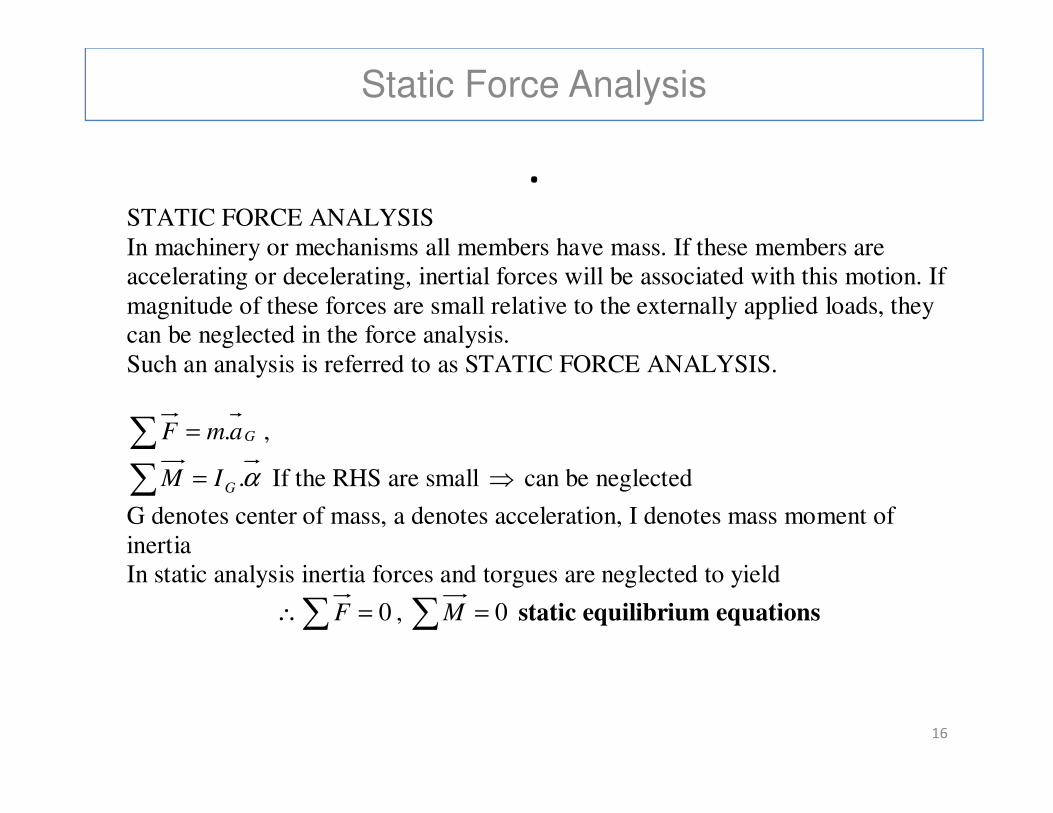
.STATIC FORCE ANALYSIS In machinery or mechanisms all members have mass. If these members are accelerating or decelerating, inertial forces will be associated with this motion. If magnitude of these forces are small relative to the externally applied loads, they can be neglected in the force analysis. Such an analysis is referred to as STATIC FORCE ANALYSIS.
16
∑ = GamF . ,
∑ = α.GIM If the RHS are small ⇒ can be neglected
G denotes center of mass, a denotes acceleration, I denotes mass moment of inertia In static analysis inertia forces and torgues are neglected to yield
∴∑ = 0F , ∑ = 0M static equilibrium equations
Static Force Analysis
.
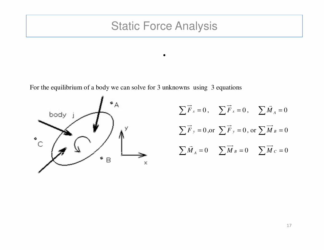
For the equilibrium of a body we can solve for 3 unknowns using 3 equations
∑ = 0xF , ∑ = 0xF , ∑ = 0AMr
∑ ∑ ∑
17
∑ = 0yF ,or ∑ = 0yF , or ∑ = 0BM
∑ = 0AMr
∑ = 0BM ∑ = 0CM
Static Force Analysis
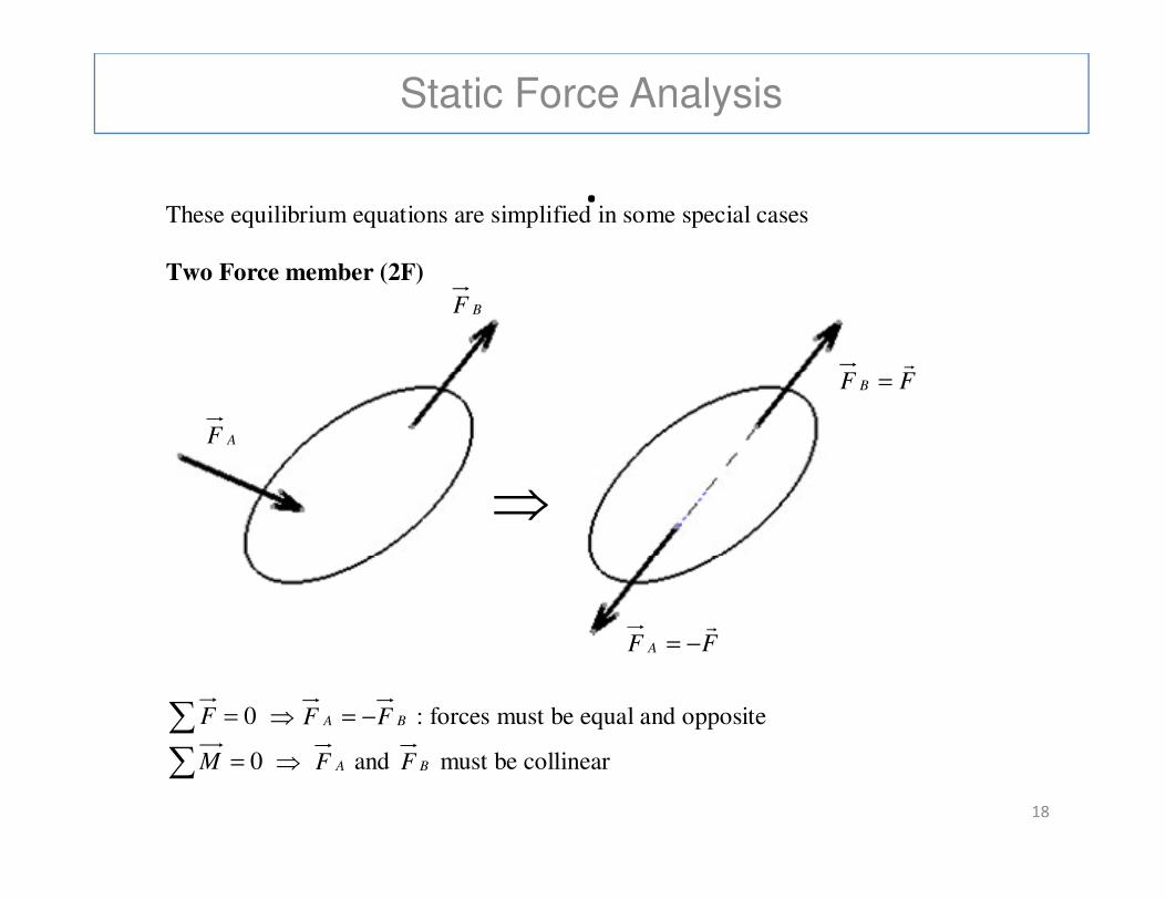
.These equilibrium equations are simplified in some special cases
Two Force member (2F)
AF
BF
FF B
r=
18
∑ = 0F ⇒ BA FF −= : forces must be equal and opposite
∑ = 0M ⇒ AF and BF must be collinear
FF A
r−=
⇒
Static Force Analysis
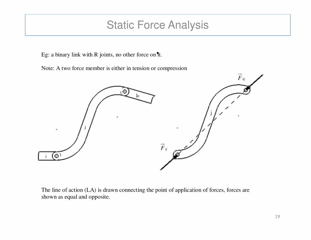
.Eg: a binary link with R joints, no other force on it. Note: A two force member is either in tension or compression
kjF
19
The line of action (LA) is drawn connecting the point of application of forces, forces are shown as equal and opposite.
ijF
Static Force Analysis
.
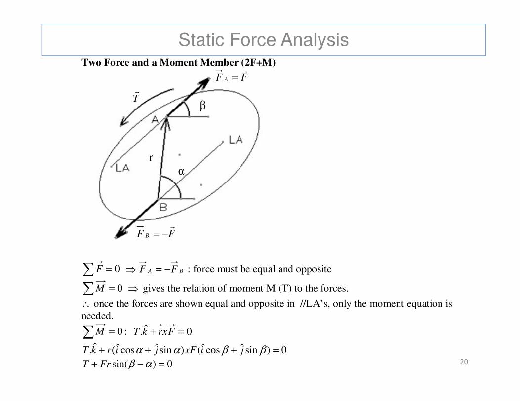
Two Force and a Moment Member (2F+M)
FF A
r=
Tr
α
β
r
20
∑ = 0F ⇒ BA FF −= : force must be equal and opposite
∑ = 0M ⇒ gives the relation of moment M (T) to the forces.
∴ once the forces are shown equal and opposite in //LA’s, only the moment equation is needed.
∑ = 0M : 0ˆ. =+ FxrkT
0)sinˆcosˆ()sinˆcosˆ(ˆ. =+++ ββαα jixFjirkT
0)sin( =−+ αβFrT
FF B
r−=
Static Force Analysis
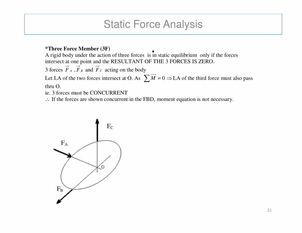
.*Three Force Member (3F)
A rigid body under the action of three forces is in static equilibrium only if the forces intersect at one point and the RESULTANT OF THE 3 FORCES IS ZERO.
3 forces AF , BF and CF acting on the body
Let LA of the two forces intersect at O. As ∑ = 0M ⇒LA of the third force must also pass
thru O. ie. 3 forces must be CONCURRENT ∴ If the forces are shown concurrent in the FBD, moment equation is not necessary.
21
FA
FB
FC

Static Force Analysis
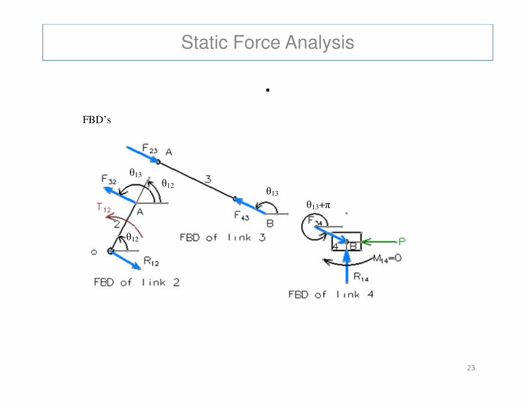
.Ex. Slider crank Mechanism
θ
θ13
22
Given force P, find T12 as a function of position variables Assume inertial forces are small compared to other forces and gravity and friction forces are negligible.
θ12
Static Force Analysis
.
FBD’s
θ13
θ13+π
θ13 θ12
23
θ13+π
θ12
Static Force Analysis
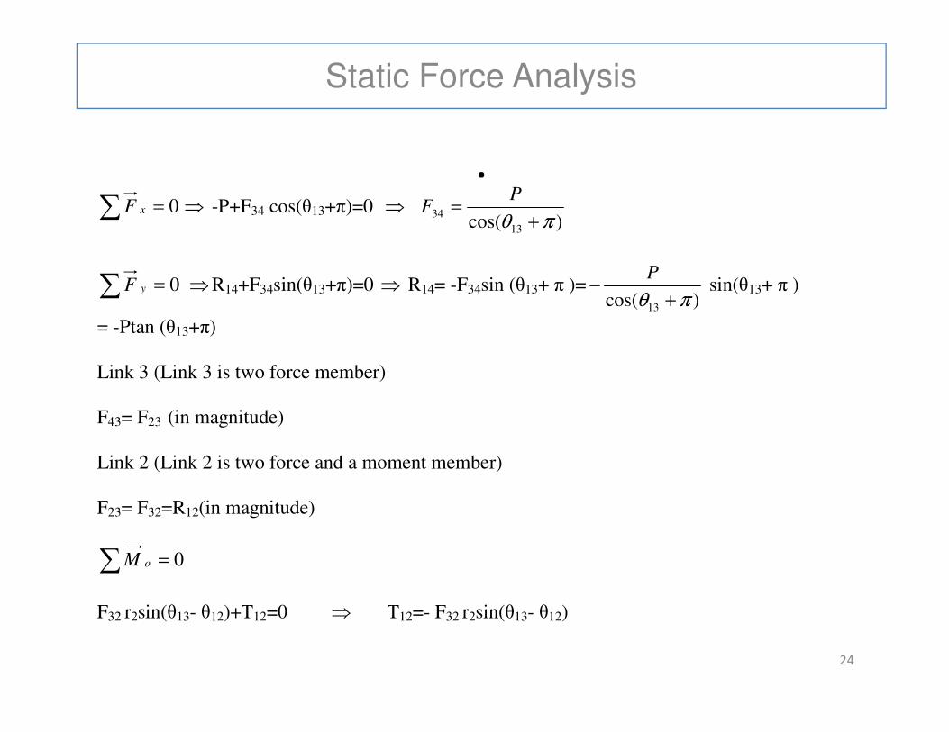
.∑ = 0xF ⇒ -P+F34 cos(θ13+π)=0 ⇒
)cos( 13
34πθ +
=P
F
∑ = 0yF ⇒R14+F34sin(θ13+π)=0 ⇒ R14= -F34sin (θ13+ π )=)cos( 13 πθ +
−P
sin(θ13+ π )
= -Ptan (θ13+π)
Link 3 (Link 3 is two force member)
24
Link 3 (Link 3 is two force member) F43= F23 (in magnitude) Link 2 (Link 2 is two force and a moment member) F23= F32=R12(in magnitude)
∑ = 0oM
F32 r2sin(θ13- θ12)+T12=0 ⇒ T12=- F32 r2sin(θ13- θ12)
Static Force Analysis
.
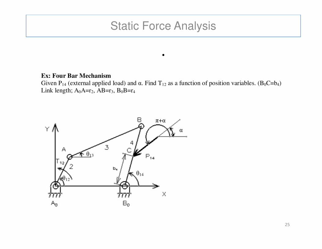
Ex: Four Bar Mechanism
Given P14 (external applied load) and α. Find T12 as a function of position variables. (B0C=b4) Link length; A0A=r2, AB=r3, B0B=r4
π+α
25
θ12
θ13
θ14
α
Static Force Analysis
.
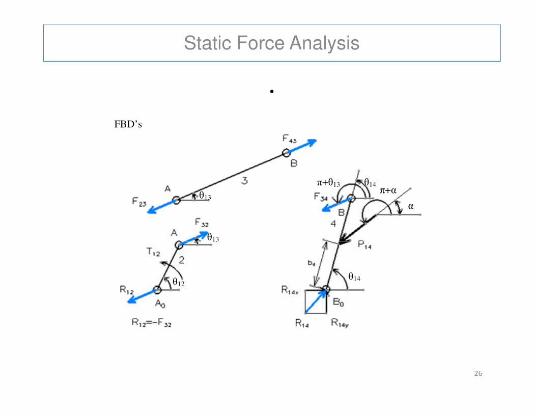
FBD’s
θ13 α
π+α π+θ13 θ14
26
θ12
θ13
θ14
α
Static Force Analysis
.
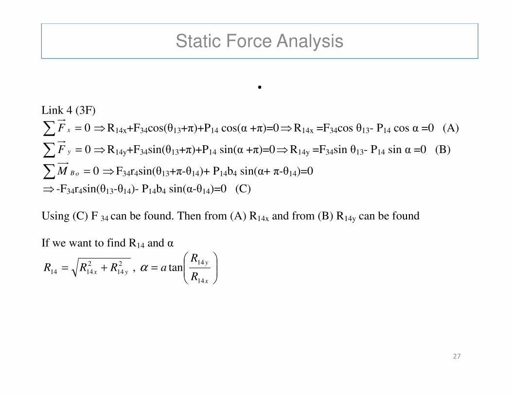
Link 4 (3F)
∑ = 0xF ⇒R14x+F34cos(θ13+π)+P14 cos(α +π)=0⇒R14x =F34cos θ13- P14 cos α =0 (A)
∑ = 0yF ⇒R14y+F34sin(θ13+π)+P14 sin(α +π)=0⇒R14y =F34sin θ13- P14 sin α =0 (B)
∑ = 0oBM ⇒F34r4sin(θ13+π-θ14)+ P14b4 sin(α+ π-θ14)=0
⇒ -F34r4sin(θ13-θ14)- P14b4 sin(α-θ14)=0 (C)
27
Using (C) F 34 can be found. Then from (A) R14x and from (B) R14y can be found
If we want to find R14 and α
2
14
2
1414 yx RRR += ,
=
x
y
R
Ra
14
14tanα
Static Force Analysis
.
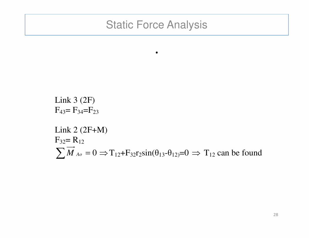
Link 3 (2F) F43= F34=F23
28
Link 2 (2F+M) F32= R12
∑ = 0AoM ⇒T12+F32r2sin(θ13-θ12)=0 ⇒ T12 can be found
Static Force Analysis
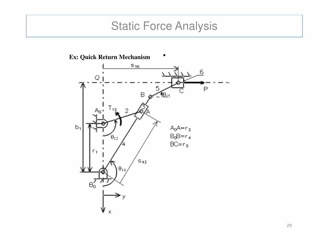
.Ex: Quick Return Mechanism
θ15
29
θ12
θ14
Static Force Analysis
.
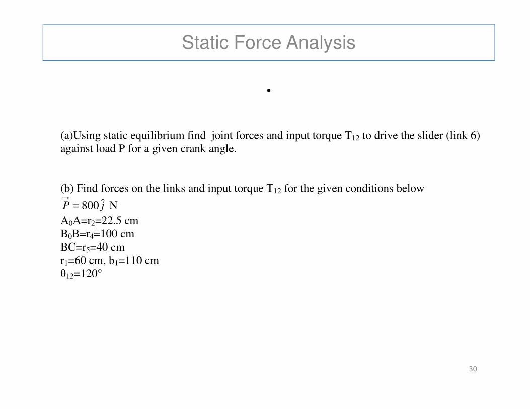
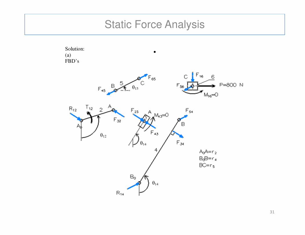
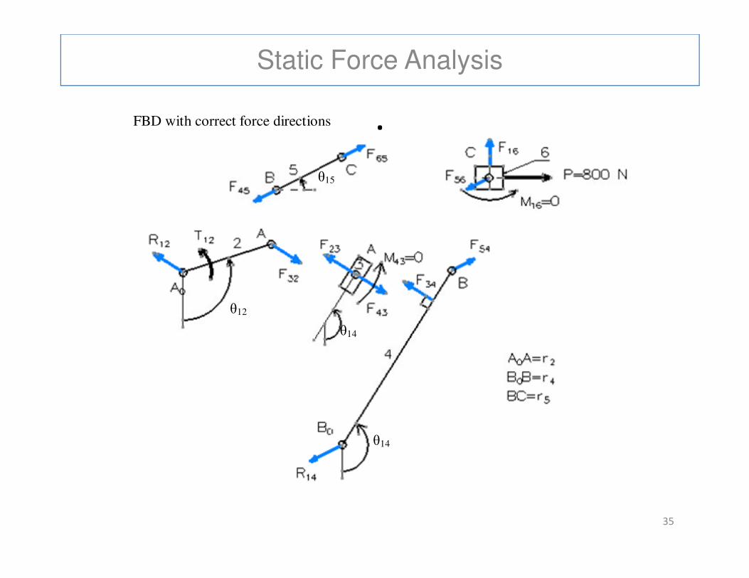
(a)Using static equilibrium find joint forces and input torque T12 to drive the slider (link 6) against load P for a given crank angle. (b) Find forces on the links and input torque T12 for the given conditions below
jP ˆ800= N
30
jP ˆ800= N
A0A=r2=22.5 cm B0B=r4=100 cm BC=r5=40 cm r1=60 cm, b1=110 cm θ12=120°
Static Force Analysis
.Solution: (a) FBD’s
θ15
31
θ12
θ14
θ14
Static Force Analysis
.
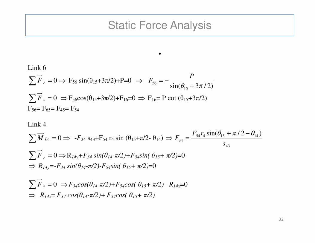
Link 6
∑ = 0yF ⇒ F56 sin(θ15+3π/2)+P=0 ⇒ )2/3sin( 15
56πθ +
−=P
F
∑ = 0xF ⇒F56cos(θ15+3π/2)+F16=0 ⇒ F16= P cot (θ15+3π/2)
F56= F65= F45= F54
Link 4
32
Link 4
∑ = 0BoM ⇒ -F34 s43+F54 r4 sin (θ15+π/2- θ14) ⇒43
141545434
)2/sin(
s
rFF
θπθ −+=
∑ = 0yF ⇒R14y+F34 sin(θ14-π/2)+F54sin( θ15+ π/2)=0
⇒ R14y=-F34 sin(θ14-π/2)-F54sin( θ15+ π/2)=0
∑ = 0xF ⇒F34cos(θ14-π/2)+F54cos( θ15+ π/2) - R14x=0
⇒ R14x= F34 cos(θ14-π/2)+ F54cos( θ15+ π/2)
Static Force Analysis
.
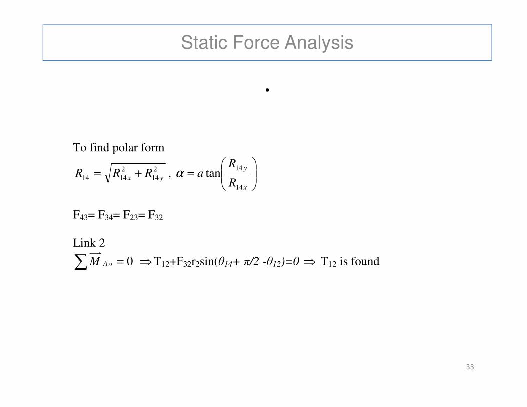
To find polar form
2
14
2
1414 yx RRR += ,
=
x
y
R
Ra
14
14tanα
33
F43= F34= F23= F32 Link 2
∑ = 0oAM ⇒T12+F32r2sin(θ14+ π/2 -θ12)=0 ⇒ T12 is found
Static Force Analysis
.
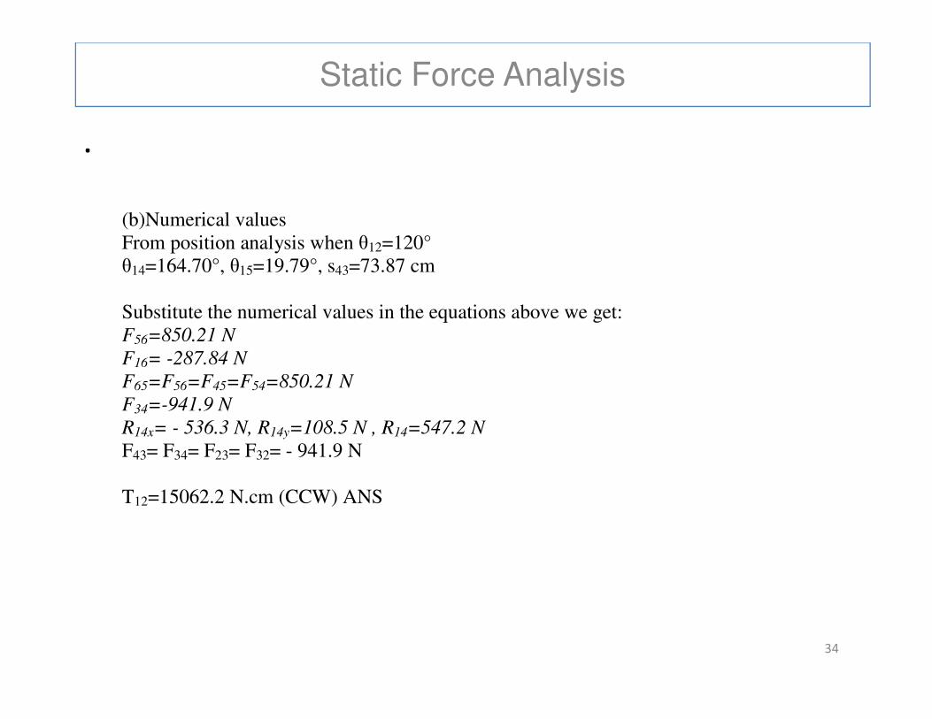
(b)Numerical values From position analysis when θ12=120° θ14=164.70°, θ15=19.79°, s43=73.87 cm Substitute the numerical values in the equations above we get: F56=850.21 N
F16= -287.84 N
34
F16= -287.84 N
F65=F56=F45=F54=850.21 N
F34=-941.9 N
R14x= - 536.3 N, R14y=108.5 N , R14=547.2 N
F43= F34= F23= F32= - 941.9 N T12=15062.2 N.cm (CCW) ANS
Static Force Analysis
.FBD with correct force directions
θ15
35
θ12
θ14
θ14
Static Force Analysis
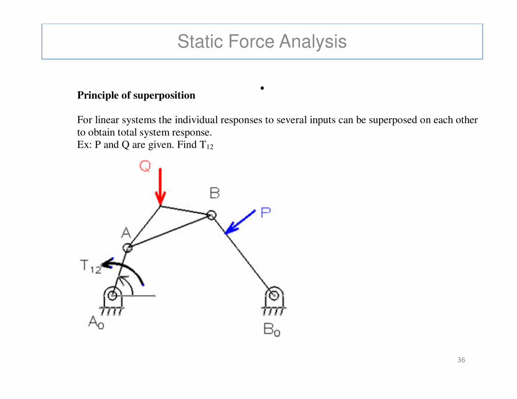
.Principle of superposition
For linear systems the individual responses to several inputs can be superposed on each other to obtain total system response. Ex: P and Q are given. Find T12
36
Static Force Analysis
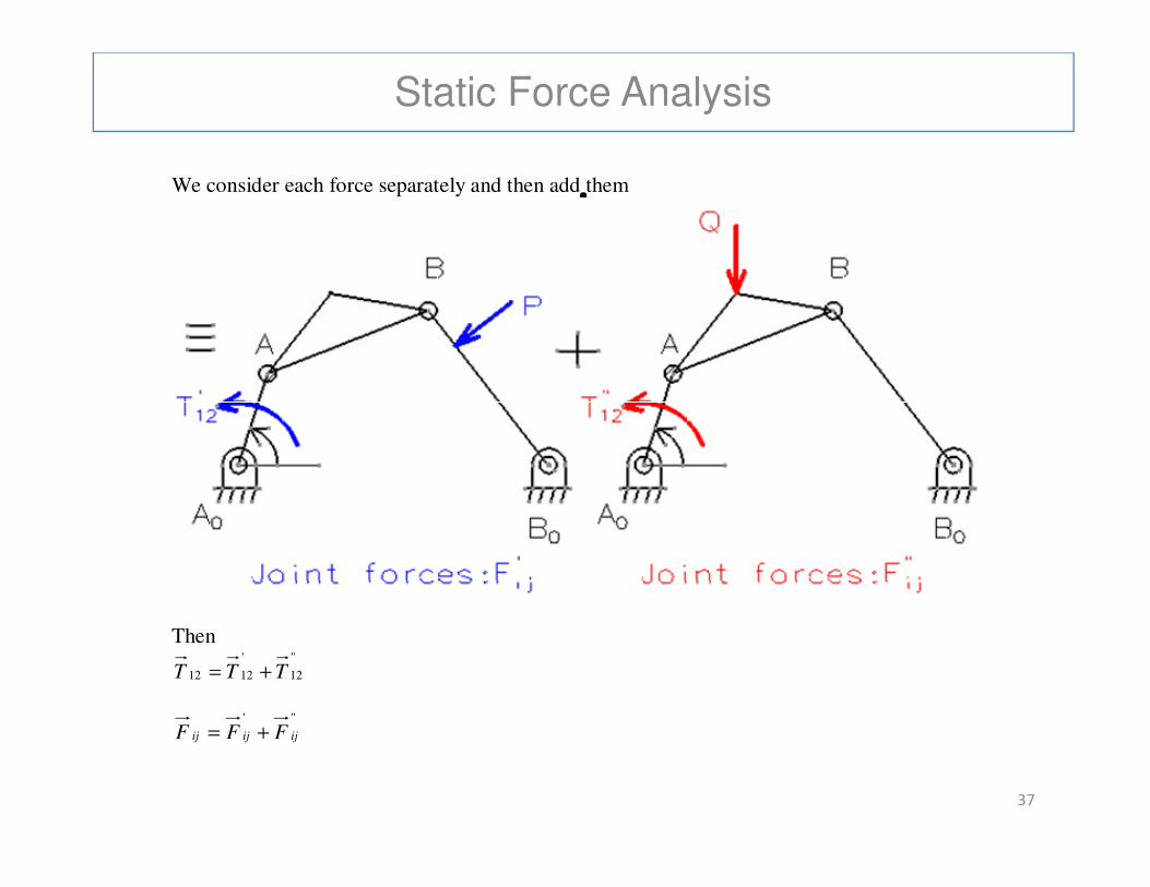
.We consider each force separately and then add them
37
Then
"
12
'
1212 TTT +=
"'
ijijij FFF +=
Static Force Analysis-Resistive Forces
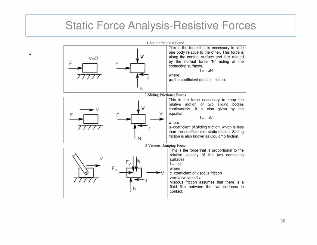
.1-Static Frictional Force
This is the force that is necessary to slide one body relative to the other. This force is along the contact surface and it is related by the normal force “N” acting at the contacting surfaces.
f = - µN where µ= the coefficient of static friction.
2-Sliding Frictional Forces
This is the force necessary to keep the relative motion of two sliding bodies continuously. It is also given by the equation:
f = - µN where
38
where µ=coefficient of sliding friction, which is less than the coefficient of static friction. Sliding friction is also known as Coulomb friction.
3-Viscous Damping Force
This is the force that is proportional to the relative velocity of the two contacting surfaces. f = - cv where c=coefficient of viscous friction v=relative velocity. Viscous friction assumes that there is a fluid film between the two surfaces in contact.
Static Force Analysis-Resistive Forces
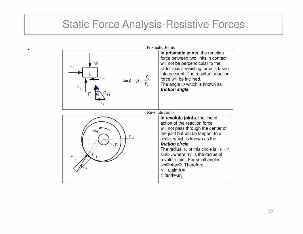
. Prismatic Joints
In prismatic joints, the reaction force between two links in contact will not be perpendicular to the slider axis if resisting force is taken into account. The resultant reaction force will be inclined. The angle Φ which is known as friction angle.
Revolute Joints
In revolute joints, the line of
ji
ij
F
f== µφtan
Ø
39
In revolute joints, the line of action of the reaction force will not pass through the center of the joint but will be tangent to a circle, which is known as the friction circle. The radius, rf, of this circle is : rf = rij sinΦ , where “rij” is the radius of revolute joint. For small angles sinΦ≈tanΦ. Therefore: rf = rij sinΦ ≈ rij tanΦ≈µrij
ωij