standing loss control vapor recovery system for … · executive order vr-301-d standing loss...
TRANSCRIPT
Executive Order VR-301-D
Standing Loss Control Vapor Recovery System for Existing Installations of Aboveground Storage Tanks Exhibit 1, Page 1
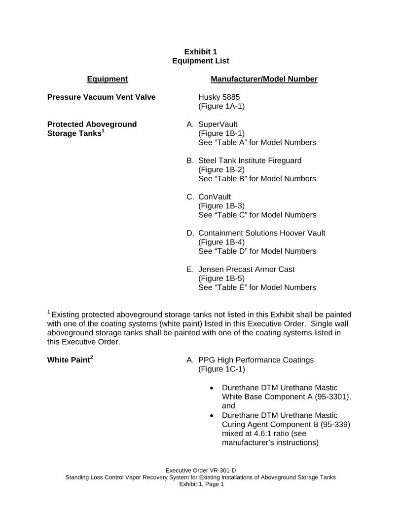
Exhibit 1 Equipment List
Equipment
Pressure Vacuum Vent Valve
Manufacturer/Model Number
Husky 5885 (Figure 1A-1)
Protected Aboveground Storage Tanks1
A. SuperVault (Figure 1B-1) See “Table A” for Model Numbers
B. Steel Tank Institute Fireguard
(Figure 1B-2) See “Table B” for Model Numbers
C. ConVault
(Figure 1B-3) See “Table C” for Model Numbers
D. Containment Solutions Hoover Vault
(Figure 1B-4) See “Table D” for Model Numbers
E. Jensen Precast Armor Cast
(Figure 1B-5) See “Table E” for Model Numbers
1 Existing protected aboveground storage tanks not listed in this Exhibit shall be painted with one of the coating systems (white paint) listed in this Executive Order. Single wall aboveground storage tanks shall be painted with one of the coating systems listed in this Executive Order. White Paint2
A. PPG High Performance Coatings
(Figure 1C-1)
• Durethane DTM Urethane Mastic White Base Component A (95-3301), and
• Durethane DTM Urethane Mastic Curing Agent Component B (95-339) mixed at 4.6:1 ratio (see manufacturer’s instructions)
Executive Order VR-301-D
Standing Loss Control Vapor Recovery System for Existing Installations of Aboveground Storage Tanks Exhibit 1, Page 2
Equipment
Manufacturer/Model Number
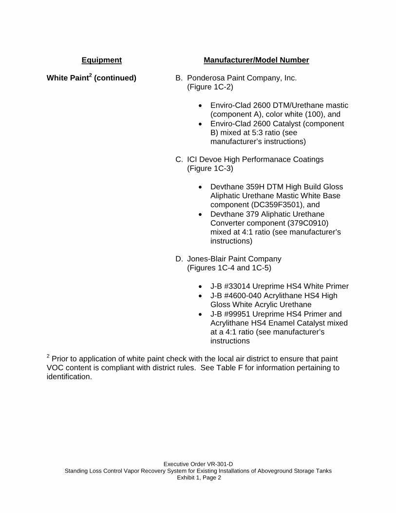
White Paint2 (continued)
B. Ponderosa Paint Company, Inc.
(Figure 1C-2)
• Enviro-Clad 2600 DTM/Urethane mastic (component A), color white (100), and
• Enviro-Clad 2600 Catalyst (component B) mixed at 5:3 ratio (see manufacturer’s instructions)
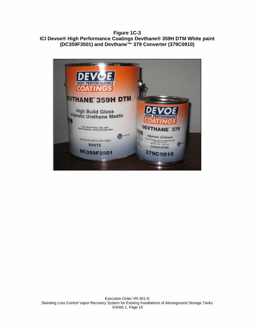
C. ICI Devoe High Performanace Coatings
(Figure 1C-3)
• Devthane 359H DTM High Build Gloss Aliphatic Urethane Mastic White Base component (DC359F3501), and
• Devthane 379 Aliphatic Urethane Converter component (379C0910) mixed at 4:1 ratio (see manufacturer’s instructions)
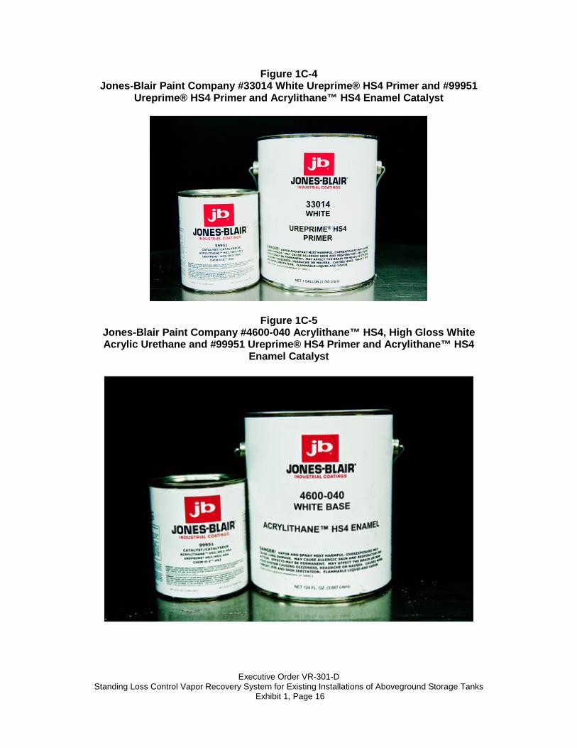
D. Jones-Blair Paint Company
(Figures 1C-4 and 1C-5)
• J-B #33014 Ureprime HS4 White Primer • J-B #4600-040 Acrylithane HS4 High
Gloss White Acrylic Urethane • J-B #99951 Ureprime HS4 Primer and
Acrylithane HS4 Enamel Catalyst mixed at a 4:1 ratio (see manufacturer’s instructions
2 Prior to application of white paint check with the local air district to ensure that paint VOC content is compliant with district rules. See Table F for information pertaining to identification.
Executive Order VR-301-D
Standing Loss Control Vapor Recovery System for Existing Installations of Aboveground Storage Tanks Exhibit 1, Page 3
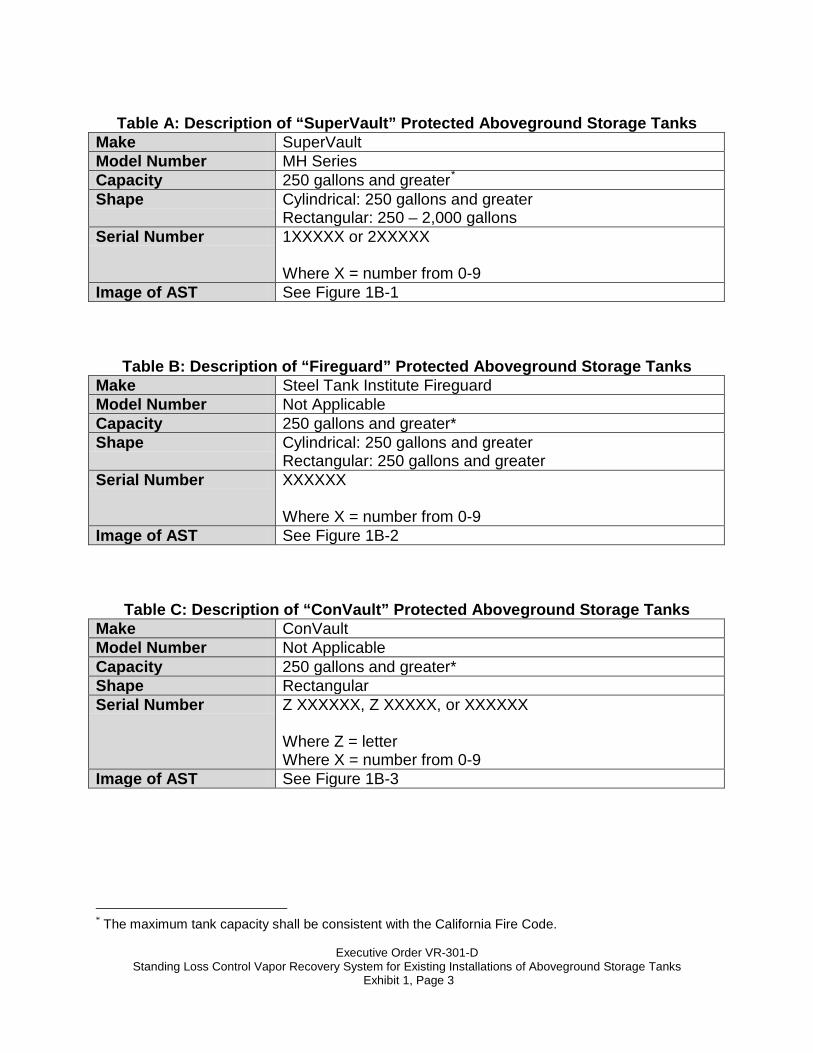
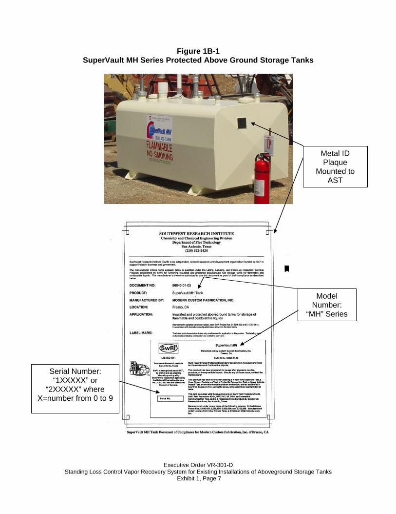
Table A: Description of “SuperVault” Protected Aboveground Storage Tanks
Make SuperVault Model Number MH Series Capacity 250 gallons and greater* Shape Cylindrical: 250 gallons and greater
Rectangular: 250 – 2,000 gallons Serial Number 1XXXXX or 2XXXXX
Where X = number from 0-9
Image of AST See Figure 1B-1
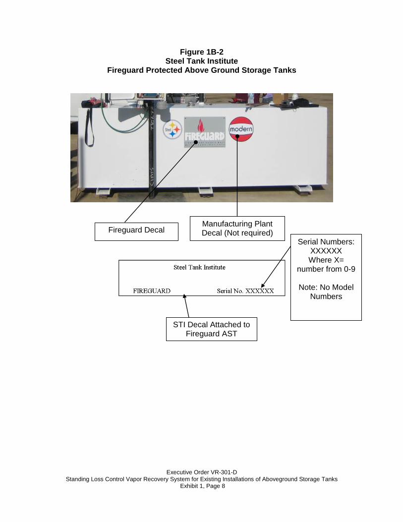
Table B: Description of “Fireguard” Protected Aboveground Storage Tanks Make Steel Tank Institute Fireguard Model Number Not Applicable Capacity 250 gallons and greater* Shape Cylindrical: 250 gallons and greater
Rectangular: 250 gallons and greater Serial Number XXXXXX
Where X = number from 0-9
Image of AST See Figure 1B-2
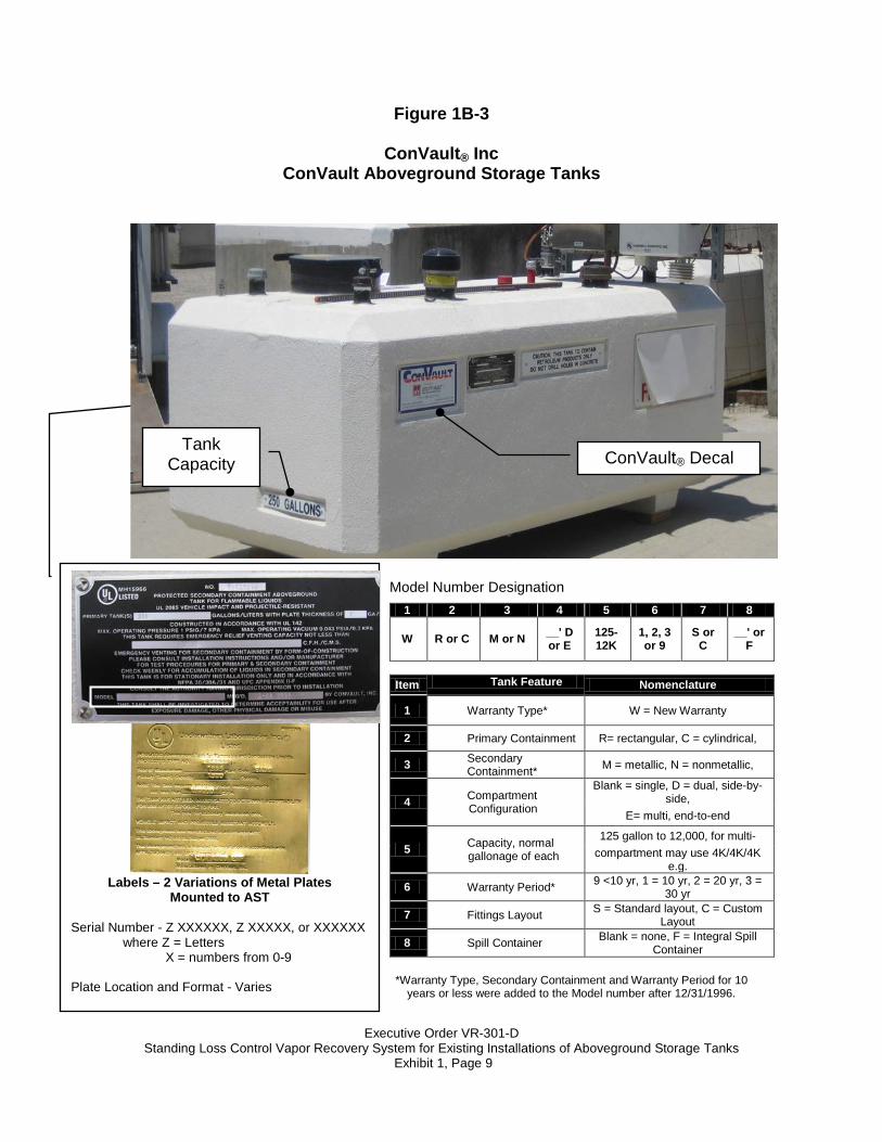
Table C: Description of “ConVault” Protected Aboveground Storage Tanks Make ConVault Model Number Not Applicable Capacity 250 gallons and greater* Shape Rectangular Serial Number Z XXXXXX, Z XXXXX, or XXXXXX
Where Z = letter Where X = number from 0-9
Image of AST See Figure 1B-3
* The maximum tank capacity shall be consistent with the California Fire Code.
Executive Order VR-301-D
Standing Loss Control Vapor Recovery System for Existing Installations of Aboveground Storage Tanks Exhibit 1, Page 4
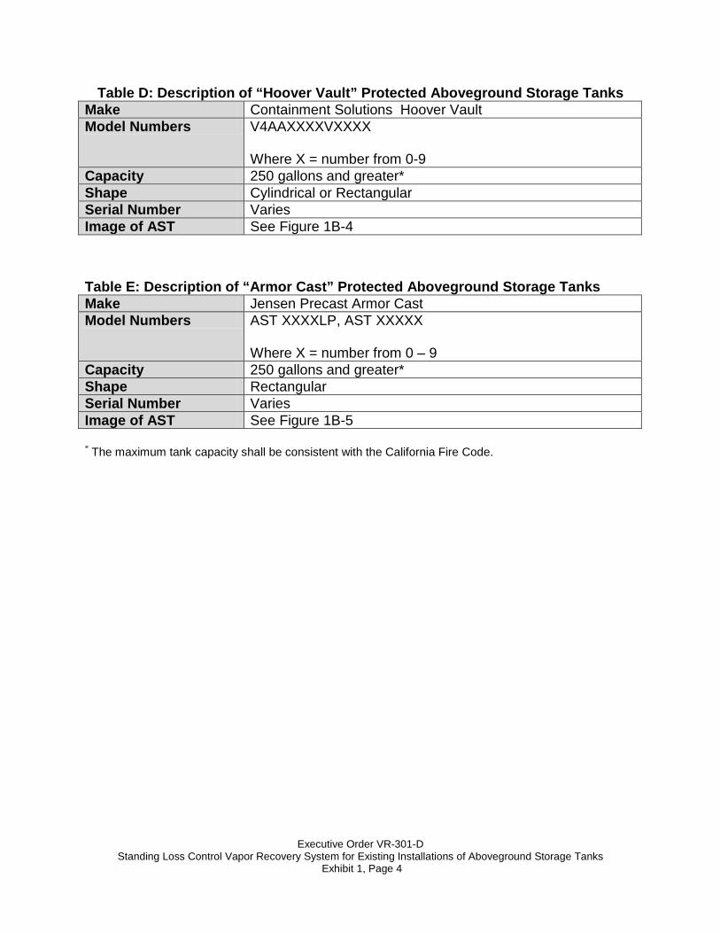
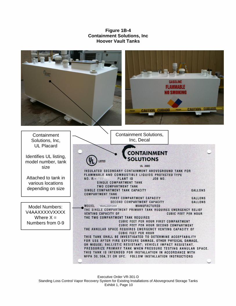
Table D: Description of “Hoover Vault” Protected Aboveground Storage Tanks Make Containment Solutions Hoover Vault Model Numbers V4AAXXXXVXXXX
Where X = number from 0-9
Capacity 250 gallons and greater* Shape Cylindrical or Rectangular Serial Number Varies Image of AST See Figure 1B-4 Table E: Description of “Armor Cast” Protected Aboveground Storage Tanks Make Jensen Precast Armor Cast Model Numbers AST XXXXLP, AST XXXXX
Where X = number from 0 – 9
Capacity 250 gallons and greater* Shape Rectangular Serial Number Varies Image of AST See Figure 1B-5 * The maximum tank capacity shall be consistent with the California Fire Code.
Executive Order VR-301-D
Standing Loss Control Vapor Recovery System for Existing Installations of Aboveground Storage Tanks Exhibit 1, Page 5
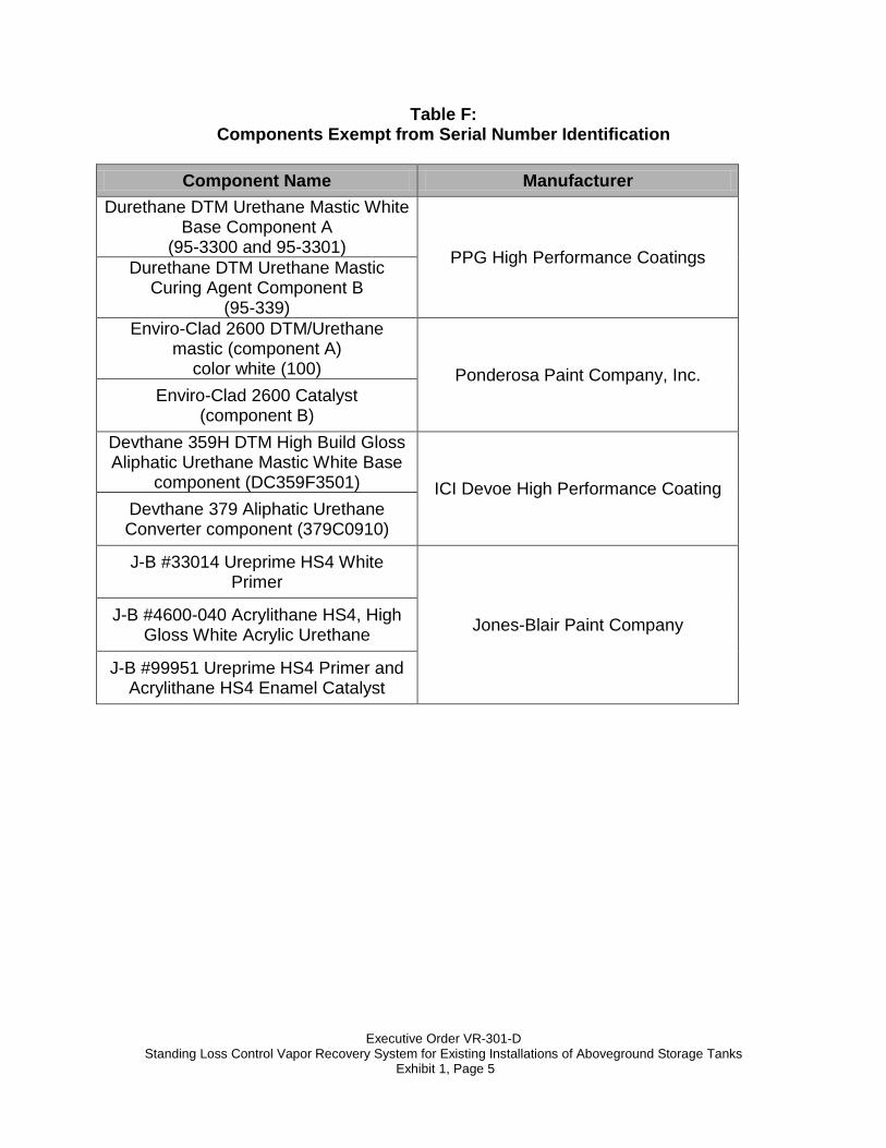
Table F: Components Exempt from Serial Number Identification
Component Name Manufacturer
Durethane DTM Urethane Mastic White Base Component A
(95-3300 and 95-3301) PPG High Performance Coatings Durethane DTM Urethane Mastic Curing Agent Component B
(95-339) Enviro-Clad 2600 DTM/Urethane
mastic (component A) color white (100) Ponderosa Paint Company, Inc.
Enviro-Clad 2600 Catalyst (component B)
Devthane 359H DTM High Build Gloss Aliphatic Urethane Mastic White Base
component (DC359F3501) ICI Devoe High Performance Coating Devthane 379 Aliphatic Urethane Converter component (379C0910)
J-B #33014 Ureprime HS4 White Primer
Jones-Blair Paint Company J-B #4600-040 Acrylithane HS4, High Gloss White Acrylic Urethane
J-B #99951 Ureprime HS4 Primer and Acrylithane HS4 Enamel Catalyst
Executive Order VR-301-D
Standing Loss Control Vapor Recovery System for Existing Installations of Aboveground Storage Tanks Exhibit 1, Page 6
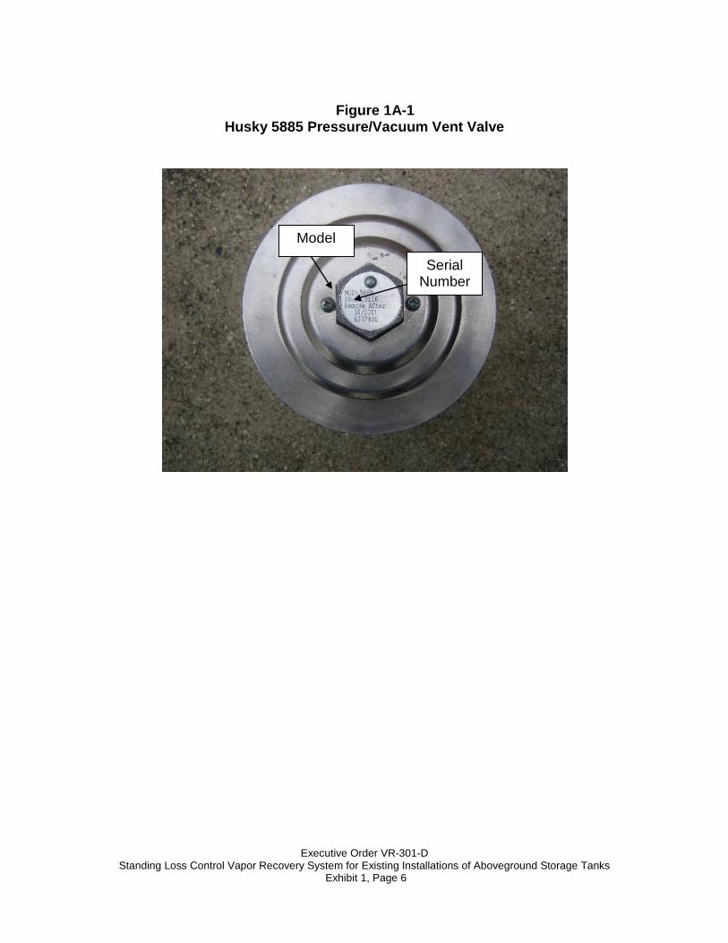
Figure 1A-1
Husky 5885 Pressure/Vacuum Vent Valve
Model
Serial Number
Executive Order VR-301-D
Standing Loss Control Vapor Recovery System for Existing Installations of Aboveground Storage Tanks Exhibit 1, Page 7
Figure 1B-1 SuperVault MH Series Protected Above Ground Storage Tanks
Metal ID Plaque
Mounted to AST
Model Number:
“MH” Series
Serial Number: “1XXXXX” or
“2XXXXX” where X=number from 0 to 9
Executive Order VR-301-D
Standing Loss Control Vapor Recovery System for Existing Installations of Aboveground Storage Tanks Exhibit 1, Page 8
Figure 1B-2 Steel Tank Institute
Fireguard Protected Above Ground Storage Tanks
Serial Numbers: XXXXXX Where X=
number from 0-9
Note: No Model Numbers
Fireguard Decal
STI Decal Attached to Fireguard AST
Manufacturing Plant Decal (Not required)
Executive Order VR-301-D
Standing Loss Control Vapor Recovery System for Existing Installations of Aboveground Storage Tanks Exhibit 1, Page 9
Labels – 2 Variations of Metal Plates
Mounted to AST
Serial Number - Z XXXXXX, Z XXXXX, or XXXXXX where Z = Letters X = numbers from 0-9
Plate Location and Format - Varies
Figure 1B-3
ConVault® Inc ConVault Aboveground Storage Tanks
Model Number Designation
*Warranty Type, Secondary Containment and Warranty Period for 10 years or less were added to the Model number after 12/31/1996.
1 2 3 4 5 6 7 8
W R or C M or N __' D or E
125-12K
1, 2, 3 or 9
S or C
__' or F
Item Tank Feature Nomenclature
1 Warranty Type* W = New Warranty
2 Primary Containment R= rectangular, C = cylindrical,
3 Secondary Containment* M = metallic, N = nonmetallic,
4 Compartment Configuration
Blank = single, D = dual, side-by-side,
E= multi, end-to-end
5 Capacity, normal gallonage of each
125 gallon to 12,000, for multi- compartment may use 4K/4K/4K
e.g.
6 Warranty Period* 9 <10 yr, 1 = 10 yr, 2 = 20 yr, 3 = 30 yr
7 Fittings Layout S = Standard layout, C = Custom Layout
8 Spill Container Blank = none, F = Integral Spill Container
ConVault® Decal Tank
Capacity
Executive Order VR-301-D
Standing Loss Control Vapor Recovery System for Existing Installations of Aboveground Storage Tanks Exhibit 1, Page 10
Figure 1B-4 Containment Solutions, Inc
Hoover Vault Tanks
Containment Solutions, Inc,
UL Placard
Identifies UL listing, model number, tank
size
Attached to tank in various locations
depending on size
Containment Solutions, Inc, Decal
Model Numbers: V4AAXXXXVXXXX
Where X = Numbers from 0-9
Executive Order VR-301-D
Standing Loss Control Vapor Recovery System for Existing Installations of Aboveground Storage Tanks Exhibit 1, Page 11
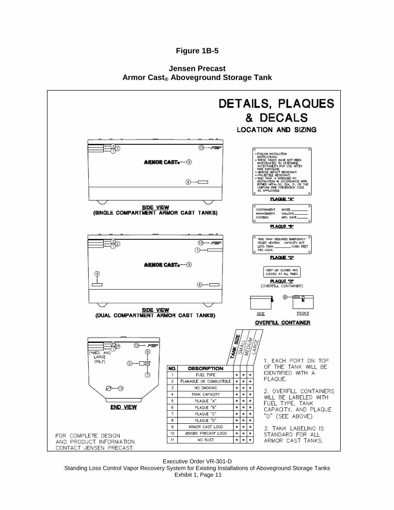
Figure 1B-5
Jensen Precast Armor Cast® Aboveground Storage Tank
Executive Order VR-301-D
Standing Loss Control Vapor Recovery System for Existing Installations of Aboveground Storage Tanks Exhibit 1, Page 12
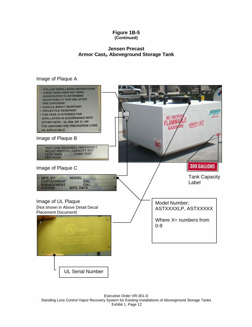
Figure 1B-5 (Continued)
Jensen Precast
Armor Cast® Aboveground Storage Tank
Image of Plaque A
Image of Plaque B
Image of Plaque C
Image of UL Plaque (Not shown in Above Detail Decal Placement Document)
Tank Capacity Label
Model Number: ASTXXXXLP, ASTXXXXX Where X= numbers from 0-9
UL Serial Number
Executive Order VR-301-D
Standing Loss Control Vapor Recovery System for Existing Installations of Aboveground Storage Tanks Exhibit 1, Page 13
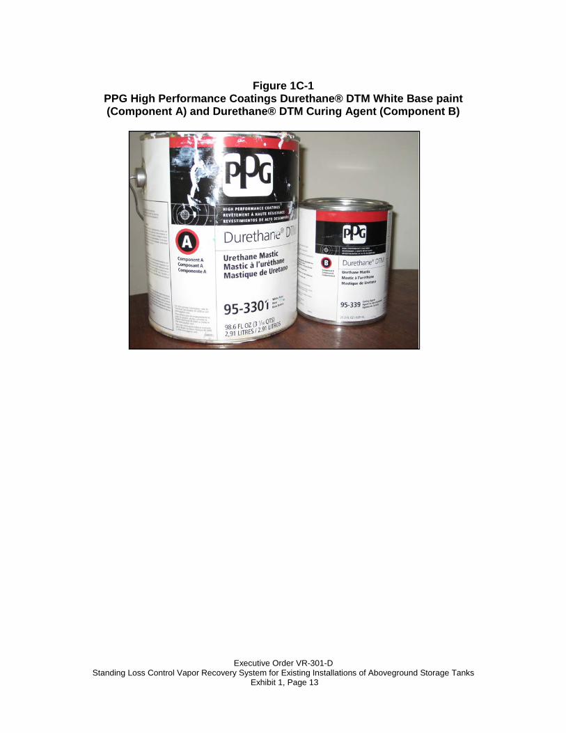
Figure 1C-1
PPG High Performance Coatings Durethane® DTM White Base paint (Component A) and Durethane® DTM Curing Agent (Component B)
Executive Order VR-301-D
Standing Loss Control Vapor Recovery System for Existing Installations of Aboveground Storage Tanks Exhibit 1, Page 14
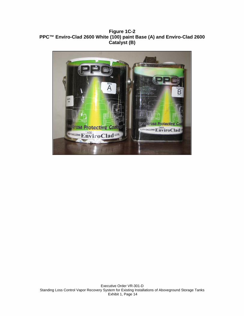
Figure 1C-2 PPC™ Enviro-Clad 2600 White (100) paint Base (A) and Enviro-Clad 2600
Catalyst (B)
Executive Order VR-301-D
Standing Loss Control Vapor Recovery System for Existing Installations of Aboveground Storage Tanks Exhibit 1, Page 15
Figure 1C-3 ICI Devoe® High Performance Coatings Devthane® 359H DTM White paint
(DC359F3501) and Devthane™ 379 Converter (379C0910)
Executive Order VR-301-D
Standing Loss Control Vapor Recovery System for Existing Installations of Aboveground Storage Tanks Exhibit 1, Page 16
Figure 1C-4 Jones-Blair Paint Company #33014 White Ureprime® HS4 Primer and #99951
Ureprime® HS4 Primer and Acrylithane™ HS4 Enamel Catalyst
Figure 1C-5 Jones-Blair Paint Company #4600-040 Acrylithane™ HS4, High Gloss White Acrylic Urethane and #99951 Ureprime® HS4 Primer and Acrylithane™ HS4
Enamel Catalyst
Executive Order VR-301-D Standing Loss Control Vapor Recovery System for Existing Installations of Aboveground Storage Tanks
Exhibit 2, Page 1
Exhibit 2 System Specifications
This Exhibit contains the installation, maintenance and compliance standards and specifications applicable to existing installations of the Standing Loss Control vapor recovery systems installed in gasoline dispensing facilities (GDF) using aboveground storage tanks (AST). General Specifications 1. Typical white paint application of the Standing Loss Control system to existing
AST is shown in Figure 2A-1.
2. Prior to application of white paint, check with the Local Air Districts to ensure that paint VOC content is compliant with district rules.
3. All Standing Loss Control Vapor Recovery System for ASTs shall be installed,
operated, and maintained in accordance with the ARB-Approved Installation, Operation, and Maintenance Manual for the Standing Loss Control Vapor Recovery System for Existing Installations of Aboveground Storage Tanks.
4. Any repair, removal, or replacement of system components shall be done in
accordance the ARB-Approved Installation, Operation, and Maintenance Manual for the Standing Loss Control Vapor Recovery System of Existing Aboveground Storage Tanks.
5. The Standing Loss Control system shall comply with the applicable
performance standards and specifications in CP-206.1 6. Any existing Protected Aboveground Storage Tanks listed in Exhibit 1 are
exempt from the application of white paint. Installation of Standing Loss Control Vapor Recovery System for Existing ASTs White Paint for Existing AST 1. Only the white paint listed in Exhibit 1 shall be applied to any GDF AST
unless the exemption expressed in item 6 of General Specifications applies. 1 If a protected tank is not painted with the original equipment manufacturer’s color, then it is to be painted with a certified coating from Exhibit 1 of VR-301, subject to Local Air District approval prior to application.
Executive Order VR-301-D Standing Loss Control Vapor Recovery System for Existing Installations of Aboveground Storage Tanks
Exhibit 2, Page 2
2. Prior to the application of the white paint, the surface of the AST shall be prepared per the paint manufacturer’s specifications listed in ARB-Approved Installation, Operation, and Maintenance Manual for the Standing Loss Control Vapor Recovery System for Existing Installations of Aboveground Storage Tanks.
3. The white paint shall be applied per the manufacturer’s specifications. The
surface of the tank must be painted white except for the application of the manufacturer’s name/model numbers and safety decals.
4. Each GDF owner/operator shall maintain the following documentation for
compliance determination (Table 2-1):
a. Record of Receipt of Sale that demonstrates the purchase date and amount of product purchased.
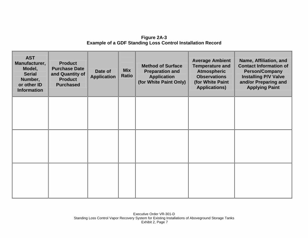
b. Record of the name and affiliation of personnel applying white paint to include the date of application, surface preparation description (i.e. scraping, sanding, abrasive blasting, primer etc.), method of application (i.e. brush, roller, air/airless sprayer), mix ratio, average ambient temperature (°F) during application, and atmospheric observations during application (i.e. sunny, cloudy, rain, etc.). An example of a Standing Loss Control Installation Record is shown in Figure 2A-3.
c. Record of the name and affiliation of personnel that installed the P/V vent valve.
d. Technical Data Sheet and/or Material Safety Data Sheet of the white paint that describes the surface preparation, application, and material safety of the white paint.
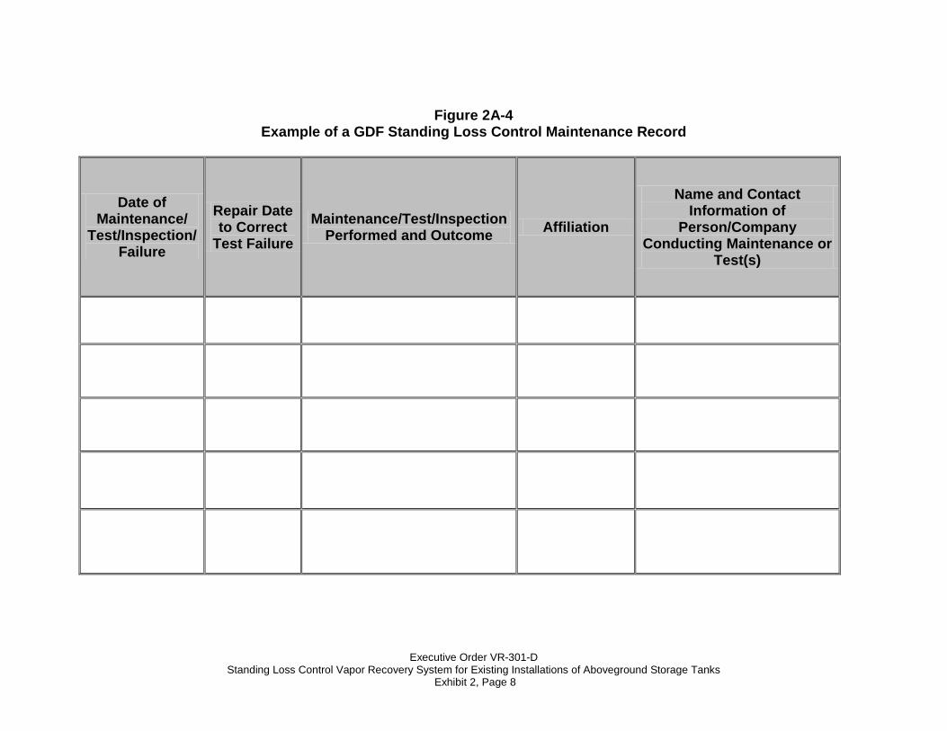
Maintenance for Existing ASTs 1. Each GDF owner/operator shall keep records of maintenance performed at
the facility. Such record shall be maintained on site or in accordance with district requirements or policies. Additional information may be required in accordance with district requirements or policies. The records shall include the maintenance or test date, repair date to correct test failure, maintenance or test performed, affiliation, telephone number, and name of individual conducting maintenance or test. Required maintenance for existing ASTs can be found in Table 2-2. An example of a Standing Loss Control Maintenance Record is shown in Figure 2A-4.
2. Maintenance shall be conducted in accordance with the maintenance section
of ARB-Approved Installation, Operation, and Maintenance Manual for
Executive Order VR-301-D Standing Loss Control Vapor Recovery System for Existing Installations of Aboveground Storage Tanks
Exhibit 2, Page 3
the Standing Loss Control Vapor Recovery System for Existing Installations of Aboveground Storage Tanks.
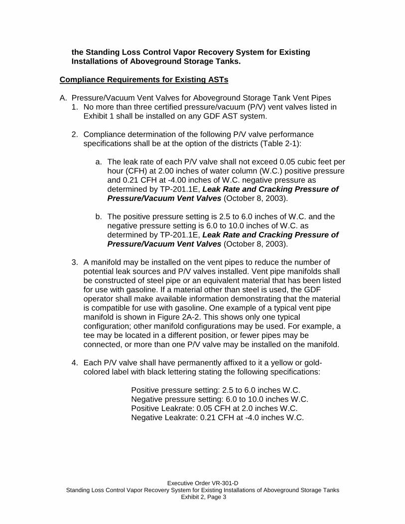
Compliance Requirements for Existing ASTs A. Pressure/Vacuum Vent Valves for Aboveground Storage Tank Vent Pipes
1. No more than three certified pressure/vacuum (P/V) vent valves listed in Exhibit 1 shall be installed on any GDF AST system.
2. Compliance determination of the following P/V valve performance
specifications shall be at the option of the districts (Table 2-1):
a. The leak rate of each P/V valve shall not exceed 0.05 cubic feet per hour (CFH) at 2.00 inches of water column (W.C.) positive pressure and 0.21 CFH at -4.00 inches of W.C. negative pressure as determined by TP-201.1E, Leak Rate and Cracking Pressure of Pressure/Vacuum Vent Valves (October 8, 2003).
b. The positive pressure setting is 2.5 to 6.0 inches of W.C. and the
negative pressure setting is 6.0 to 10.0 inches of W.C. as determined by TP-201.1E, Leak Rate and Cracking Pressure of Pressure/Vacuum Vent Valves (October 8, 2003).
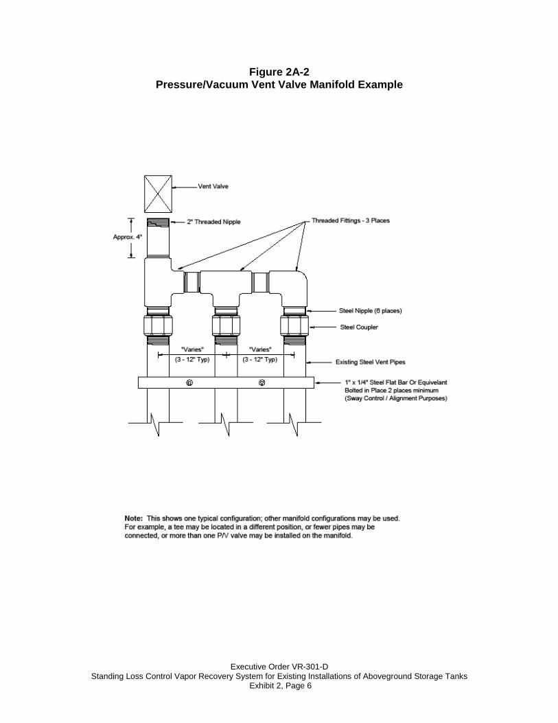
3. A manifold may be installed on the vent pipes to reduce the number of
potential leak sources and P/V valves installed. Vent pipe manifolds shall be constructed of steel pipe or an equivalent material that has been listed for use with gasoline. If a material other than steel is used, the GDF operator shall make available information demonstrating that the material is compatible for use with gasoline. One example of a typical vent pipe manifold is shown in Figure 2A-2. This shows only one typical configuration; other manifold configurations may be used. For example, a tee may be located in a different position, or fewer pipes may be connected, or more than one P/V valve may be installed on the manifold.
4. Each P/V valve shall have permanently affixed to it a yellow or gold-
colored label with black lettering stating the following specifications:
Positive pressure setting: 2.5 to 6.0 inches W.C. Negative pressure setting: 6.0 to 10.0 inches W.C. Positive Leakrate: 0.05 CFH at 2.0 inches W.C. Negative Leakrate: 0.21 CFH at -4.0 inches W.C.
Executive Order VR-301-D Standing Loss Control Vapor Recovery System for Existing Installations of Aboveground Storage Tanks
Exhibit 2, Page 4
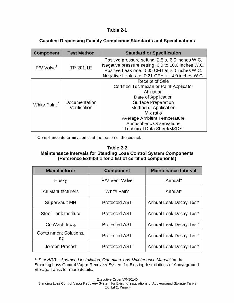
Table 2-1
Gasoline Dispensing Facility Compliance Standards and Specifications Component Test Method Standard or Specification
P/V Valve1 TP-201.1E
Positive pressure setting: 2.5 to 6.0 inches W.C. Negative pressure setting: 6.0 to 10.0 inches W.C. Positive Leak rate: 0.05 CFH at 2.0 inches W.C.
Negative Leak rate: 0.21 CFH at -4.0 inches W.C.
White Paint 1 Documentation Verification
Receipt of Sale Certified Technician or Paint Applicator
Affiliation Date of Application Surface Preparation
Method of Application Mix ratio
Average Ambient Temperature Atmospheric Observations
Technical Data Sheet/MSDS 1 Compliance determination is at the option of the district.
Table 2-2 Maintenance Intervals for Standing Loss Control System Components
(Reference Exhibit 1 for a list of certified components)
Manufacturer Component Maintenance Interval
Husky P/V Vent Valve Annual*
All Manufacturers White Paint Annual*
SuperVault MH Protected AST Annual Leak Decay Test*
Steel Tank Institute Protected AST Annual Leak Decay Test*
ConVault Inc ® Protected AST Annual Leak Decay Test*
Containment Solutions, Inc Protected AST Annual Leak Decay Test*
Jensen Precast Protected AST Annual Leak Decay Test*
* See ARB – Approved Installation, Operation, and Maintenance Manual for the Standing Loss Control Vapor Recovery System for Existing Installations of Aboveground Storage Tanks for more details.

Executive Order VR-301-D Standing Loss Control Vapor Recovery System for Existing Installations of Aboveground Storage Tanks
Exhibit 2, Page 5
Figure 2A-1 Typical installation of the Standing Loss Control system to an existing AST
Aboveground Storage Tank
P/V Vent Valve White Paint
White Paint
P/V Vent Valve
P/V Vent Valve
Executive Order VR-301-D Standing Loss Control Vapor Recovery System for Existing Installations of Aboveground Storage Tanks
Exhibit 2, Page 6
Figure 2A-2 Pressure/Vacuum Vent Valve Manifold Example
Executive Order VR-301-D Standing Loss Control Vapor Recovery System for Existing Installations of Aboveground Storage Tanks
Exhibit 2, Page 7
Figure 2A-3 Example of a GDF Standing Loss Control Installation Record
AST Manufacturer,
Model, Serial
Number, or other ID Information
Product Purchase Date and Quantity of
Product Purchased
Date of Application
Mix
Ratio
Method of Surface Preparation and
Application (for White Paint Only)
Average Ambient Temperature and
Atmospheric Observations
(for White Paint Applications)
Name, Affiliation, and Contact Information of
Person/Company Installing P/V Valve
and/or Preparing and Applying Paint
Executive Order VR-301-D Standing Loss Control Vapor Recovery System for Existing Installations of Aboveground Storage Tanks
Exhibit 2, Page 8
Figure 2A-4 Example of a GDF Standing Loss Control Maintenance Record
Date of Maintenance/
Test/Inspection/Failure
Repair Date to Correct
Test Failure Maintenance/Test/Inspection
Performed and Outcome Affiliation
Name and Contact Information of
Person/Company Conducting Maintenance or
Test(s)
Executive Order VR-301-D Standing Loss Control Vapor Recovery System for Existing Installations of Aboveground Storage Tanks
Exhibit 3, Page 1
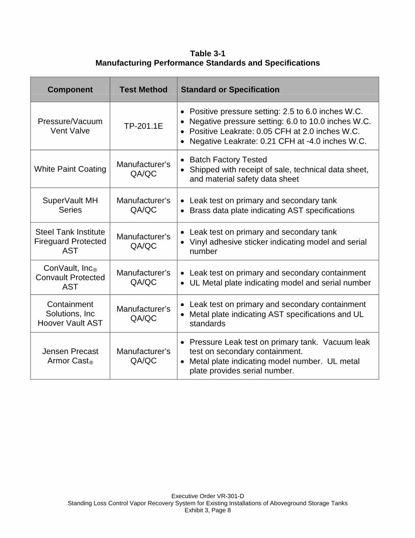
Exhibit 3 Manufacturing Performance Standards and Specifications
The Standing Loss Control Vapor Recovery System and all components shall be manufactured in compliance with the performance standard and specifications in CP-206, as well as the requirements specified in this Executive Order. All components shall be manufactured as certified; no change to the equipment, parts, design, materials or manufacturing process shall be made unless approved in writing by the Executive Officer. Unless specified in Exhibit 2 or in the ARB approved Installation, Operation and Maintenance Manual for the Standing Loss Control Vapor Recovery System for Existing Installations of Aboveground Storage Tanks, the requirements of this section apply to the manufacturing process and are not appropriate for determining the compliance status of a Gasoline Dispensing Facility (GDF). Pressure/Vacuum Vent Valve of Aboveground Storage Tank Vent Pipes 1. Each Pressure/Vacuum Vent Valve (P/V valve) shall be performance tested
at the factory for cracking pressure and leak rate at each specified pressure setting and shall be done in accordance with TP-201.1E, Leak Rate and Cracking Pressure of Pressure/Vacuum Vent Valves (October 8, 2003).
2. Each P/V valve shall be shipped with a card or label stating the performance
specifications listed in Table 3-1, and a statement that the P/V valve was tested to, and met, these specifications.
3. Each P/V valve shall have permanently affixed to it a yellow or gold label with
black lettering listing the positive and negative pressure settings listed in Table 3-1. The lettering of the label shall have a minimum font size of 20.
White Paint Coating of Aboveground Storage Tank Surface 1. Each white paint coating batch shall be performance tested at the factory to
verify it meets the manufacturer’s quality assurance/quality control standards consistent with ISO 9001, Underwriter Laboratory (UL), and/or American Standards for Testing and Materials (ASTM) guidelines for the paint/coating industry.
2. Each white paint coating will be shipped with an original receipt of sale,
technical data sheet, and material safety data sheet.
Executive Order VR-301-D Standing Loss Control Vapor Recovery System for Existing Installations of Aboveground Storage Tanks
Exhibit 3, Page 2
SuperVault MH Series Protected Above Ground Storage Tanks (SuperVault)
1. All primary and secondary walls on the SuperVault ASTs will be constructed with a minimum 3/16” thick steel and contain a 6” interstice (interior wall space). The 6” interstice will be filled with a light weight concrete mixture per manufacturer’s specifications.
2. All SuperVault ASTs will be tested during the fabrication process by applying
5 psi of positive pressure internally and externally applying a leak detecting solution to all seams and joints. This test is performed on both the primary and the secondary tanks per manufacturer’s specifications.
3. All SuperVault ASTs will be affixed with a brass data plate indicating the
manufacturer, model, serial, and the “SwRI” logo indicating compliance with other national standards
4. A quality control inspector will conduct the final visual check on the
SuperVault AST before delivery.
Steel Tank Institute Fireguard Protected Above Ground Storage Tanks (Fireguard) 1. All primary and secondary walls on the Fireguard Protected ASTs will be
constructed with a minimum 1/8” (10 gauge) thick steel and contain either a 3” or 6” interstice (interior wall space). The interstice will be filled with a propriety concrete mixture per manufacturer’s specifications.
2. All Fireguard Protected ASTs will be tested during the fabrication process by
applying 1.5 to 5 psi to the primary as well as the interstice to verify the leak integrity per manufacturer’s specifications.
3. All Fireguard Protected ASTs will be affixed with the “Fireguard” logo
indicating the Protected AST series. Also, a separate vinyl adhesive sticker will be on each Fireguard Protected AST indicating the serial number.
Executive Order VR-301-D Standing Loss Control Vapor Recovery System for Existing Installations of Aboveground Storage Tanks
Exhibit 3, Page 3
ConVault® Above Ground Storage Tanks 1. All primary tank steel plates will be constructed with a minimum of 1/8” for
tanks with 1,000 gallon capacity or less and with a minimum of 3/16” for tanks 1,500 or larger. All parts of steel tank must be constructed in accordance with UL 142 Standard. Primary tank shall be pressure tested to 5 psig for a period of 24 to 48 hours.
2. Secondary containment of ConVault® tank shall be manufactured with a
minimum of 1/4” Styrofoam, 30 mil thick High Density Polyethylene (HDPE) liner and 6” thick reinforced concrete. Concrete shall have a minimum of 4,000 psig compressive strength for tanks 2,000 gallon and smaller and 5,000 psig for tank larger than 2,000 gallon. Secondary containment should be vacuum tested to 10 inch mercury in accordance with the manufacturer and UL approved testing procedures.
3. All primary tanks shall be pressure tested both at the steel fabricating plant
and at the pre-casting plant. The secondary containment at pre-casting plant shall be vacuum tested. Additional tests performed on the concrete will include: a slump test, an air entrainment on wet concrete and a compressive concrete strength test for the duration of 7 days, 14 days and 28 days.
4. All connections to the primary tank should be either powder coated in
accordance with manufacturer Powder Coating Specifications or made of stainless steel to resist corrosion.
5. All ConVault® tanks will be affixed with a metal plate indicating the
manufacturer, tank model and UL serial number indicating compliance with national fire codes and standards.
6. A quality control inspection will be performed on each tank during the
manufacturing process and also prior to the tank delivery. The inspection is performed by quality a control personnel that is independent of production personnel. To ensure quality control standard checklists are utilized for inspection. There are separate checklists for the steel tank, pre-casting of vault, and installation of the tank.
Executive Order VR-301-D Standing Loss Control Vapor Recovery System for Existing Installations of Aboveground Storage Tanks
Exhibit 3, Page 4
Containment Solutions, Inc Hoover Vault Aboveground Storage Tanks 1. All primary and secondary walls on the Hoover Vault ASTs will be constructed
with a minimum 3/16” thick steel and contain a 4” to 6” interstice. The interstice will be filled with a light weight concrete mixture per manufacturer’s specifications.
2. The primary storage tank is constructed and listed in accordance with UL 142
Standards. Per UL 142, the primary tank is pressure tested at the factory (3 to 5 psi) and in the field by the contractor (to a maximum 3 psi).
3. The secondary tank is designed and listed according to UL 2085 (insulated
secondary ASTs). The secondary tank is tested liquid tight at the factory (3 to 5 psi) and in the field by the contractor (to a maximum 3 psi).
4. The exterior surface of the secondary tank shall be cleansed of foreign
material and coated with a corrosion resistant industrial paint with a standard color of desert sand.
5. The tank shall be labeled with a metal plate indicating the manufacturer, tank
model and UL serial number indicating compliance with national fire codes and standards.
Executive Order VR-301-D Standing Loss Control Vapor Recovery System for Existing Installations of Aboveground Storage Tanks
Exhibit 3, Page 5
Jensen Precast Armor Cast® Aboveground Storage Tanks 1. General
1.1 The fuel containment system shall be designed and tested in strict accordance with UL subject 2085 listing. The UL subject 2085 listing for insulated above ground tanks for flammable liquids shall encompass both fire protective and fire resistance.
1.2 The tank owner is responsible for ensuring that the fuel containment system shall meet all local, state, and federal codes pertaining to above, around storage of flammable and combustible liquids including N.F.P.A. 30 and 30A and the Uniform Fire Code 79-7.
1.3 Numbered brass plaques issued by Underwriters Laboratories, Inc. confirming UL subject 2085 listing shall be installed on the vault and be clearly visible to inspectors and shall identify plant location.
2. Primary Containment Tank
2.1 The primary tank shall be manufactured from mild carbon steel with a thickness of 10 gauge or greater.
2.2 The primary tank shall comply with UL 142 and NFPA 30 specifications applicable to above ground flammable liquid storage.
2.3 The primary tank exterior shall be coated with a rust inhibiting oxide primer.
2.4 The primary tank shall be pressure tested to hold 3 psi for a 1 hour period. Test results shall be kept on file by the manufacturer and be available to inspectors.
2.5 The primary tank shall be cast as an integral part of the concrete lid and must allow for future visual inspection, repair or recycling of the tank components.
3. Insulation
3.1 A minimum of 1” think rigid polystyrene insulation shall be permanently affixed to the inside of the concrete encasement.
3.2 Insulation shall be located between the 6” think concrete encasement and the 30 mil liner to ensure protection in case of primary tank failure.
Executive Order VR-301-D Standing Loss Control Vapor Recovery System for Existing Installations of Aboveground Storage Tanks
Exhibit 3, Page 6
4. Tertiary Concrete Encasement
4.1 The concrete encasement shall be a one piece monolithically cast concrete vault, with removable and accessible cast in place interlocking beveled and sealed top lid, therefore facilitating repairs, required visual inspections, or service to primary tank.
4.2 The concrete encasement shall be a minimum of 6” thick and have a minimum compressive strength of 4000 psi.
4.3 The concrete encasement reinforcement shall be in accordance with ASTM A615 and/or ASTM A185. The steel reinforcing schedule shall be either 6” X 6” X 6 gauges steel mesh wire and/or equivalent to #4 steel rod — tied 12” on centers each way.
4.4 The concrete encasement shall be designed and testes to provide a minimum 2 hour fire protection for the primary tank, in strict accordance with UL Subject 2085 listing.
4.5 The sealant securing the lid to the concrete encasement shall be a UL listed system providing a minimum four (4) hour fire protection and conform to the uniform fire code standards for rapid rise fire tests.
4.6 The containment system shall allow for the introduction of monitoring (leak detection) devices in the tertiary containment space by means of a 2” diameter leak detection tube.
4.7 Provisions for seismic restraints shall be installed where required by code.
5. Exterior Protection
5.1 The concrete surface shall be clean, dry, completely cured, and free of any form of release agents.
5.2 The exterior surface shall be one of two (2) finish treatments.
(1) Finished Exterior shall be Exposed Aggregate finish with a Clear Fuel Resistant Epoxy Coating.
(2) Finished Exterior shall be colored (Standard Color White) 2-Part Fuel Resistant Epoxy Coating.
5.3 The primer coat shall be a two part epoxy for the primer (one coat).
5.4 The two finish coats shall be a high quality two part epoxy and be resistant to petroleum products. Standard color shall be white unless noted otherwise.
Executive Order VR-301-D Standing Loss Control Vapor Recovery System for Existing Installations of Aboveground Storage Tanks
Exhibit 3, Page 7
5.5 Labels and safety decals shall be applied at the factory in controlled conditions ensuring proper adhesion.
6. Auxiliary Equipment and Accessories
6.1 Steel or Aluminum ladders shall be included. Stairs and railing shall be available as shown on drawings or as site conditions warrant.
6.2 A protective primer coating shall be applied to all equipment hardware to prevent corrosive bleeding onto the tank.
6.3 Two finish coats of protective rust inhibiting enamel shall be applied to all equipment hardware to prevent corrosive bleeding onto the tank.
7. Concrete Foundation Slabs
7.1 The concrete vaulted containment system shall be set on a concrete foundation or onto a level aggregate prepared surface in strict accordance with the manufacturer’s recommendations and must be specific to bearing weight and site conditions. Length, width, and thickness will vary depending upon vault size and site conditions.
7.2 The foundation slab shall be reinforced concrete formed and poured a the job site or shall be reinforced pre-cast concrete. Non-shrink grout or an elastomeric bearing pad shall be placed between the support legs and the concrete foundation slab to ensure uniform bearing.
Executive Order VR-301-D Standing Loss Control Vapor Recovery System for Existing Installations of Aboveground Storage Tanks
Exhibit 3, Page 8
Table 3-1 Manufacturing Performance Standards and Specifications
Component Test Method Standard or Specification
Pressure/Vacuum Vent Valve TP-201.1E
• Positive pressure setting: 2.5 to 6.0 inches W.C. • Negative pressure setting: 6.0 to 10.0 inches W.C. • Positive Leakrate: 0.05 CFH at 2.0 inches W.C. • Negative Leakrate: 0.21 CFH at -4.0 inches W.C.
White Paint Coating Manufacturer’s QA/QC
• Batch Factory Tested • Shipped with receipt of sale, technical data sheet,
and material safety data sheet
SuperVault MH Series
Manufacturer’s QA/QC
• Leak test on primary and secondary tank • Brass data plate indicating AST specifications
Steel Tank Institute Fireguard Protected
AST
Manufacturer’s QA/QC
• Leak test on primary and secondary tank • Vinyl adhesive sticker indicating model and serial
number
ConVault, Inc® Convault Protected
AST
Manufacturer’s QA/QC
• Leak test on primary and secondary containment • UL Metal plate indicating model and serial number
Containment Solutions, Inc
Hoover Vault AST
Manufacturer’s QA/QC
• Leak test on primary and secondary containment • Metal plate indicating AST specifications and UL
standards
Jensen Precast Armor Cast®
Manufacturer’s QA/QC
• Pressure Leak test on primary tank. Vacuum leak test on secondary containment.
• Metal plate indicating model number. UL metal plate provides serial number.
Executive Order VR-301-D Standing Loss Control Vapor Recovery System for Existing Installations of AST
Exhibit 4, Page 1
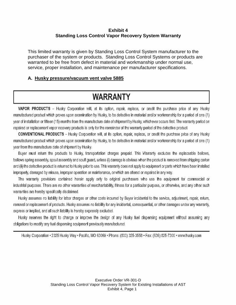
Exhibit 4 Standing Loss Control Vapor Recovery System Warranty
This limited warranty is given by Standing Loss Control System manufacturer to the purchaser of the system or products. Standing Loss Control Systems or products are warranted to be free from defect in material and workmanship under normal use, service, proper installation, and maintenance per manufacturer specifications. A. Husky pressure/vacuum vent valve 5885
Executive Order VR-301-D Standing Loss Control Vapor Recovery System for Existing Installations of AST
Exhibit 4, Page 2
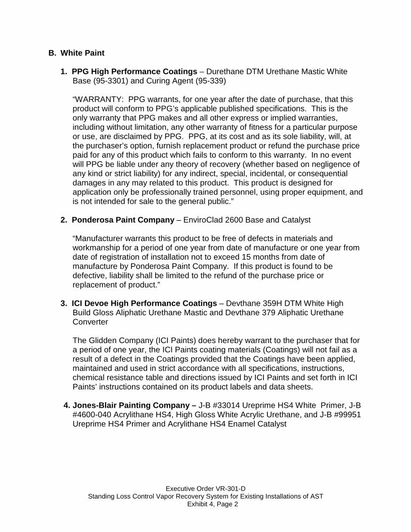
B. White Paint 1. PPG High Performance Coatings – Durethane DTM Urethane Mastic White
Base (95-3301) and Curing Agent (95-339)
“WARRANTY: PPG warrants, for one year after the date of purchase, that this product will conform to PPG’s applicable published specifications. This is the only warranty that PPG makes and all other express or implied warranties, including without limitation, any other warranty of fitness for a particular purpose or use, are disclaimed by PPG. PPG, at its cost and as its sole liability, will, at the purchaser’s option, furnish replacement product or refund the purchase price paid for any of this product which fails to conform to this warranty. In no event will PPG be liable under any theory of recovery (whether based on negligence of any kind or strict liability) for any indirect, special, incidental, or consequential damages in any may related to this product. This product is designed for application only be professionally trained personnel, using proper equipment, and is not intended for sale to the general public.”
2. Ponderosa Paint Company – EnviroClad 2600 Base and Catalyst
“Manufacturer warrants this product to be free of defects in materials and
workmanship for a period of one year from date of manufacture or one year from date of registration of installation not to exceed 15 months from date of manufacture by Ponderosa Paint Company. If this product is found to be defective, liability shall be limited to the refund of the purchase price or replacement of product.”
3. ICI Devoe High Performance Coatings – Devthane 359H DTM White High
Build Gloss Aliphatic Urethane Mastic and Devthane 379 Aliphatic Urethane Converter
The Glidden Company (ICI Paints) does hereby warrant to the purchaser that for a period of one year, the ICI Paints coating materials (Coatings) will not fail as a result of a defect in the Coatings provided that the Coatings have been applied, maintained and used in strict accordance with all specifications, instructions, chemical resistance table and directions issued by ICI Paints and set forth in ICI Paints’ instructions contained on its product labels and data sheets.
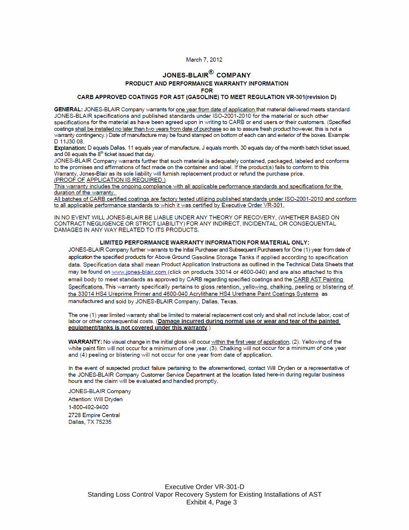
4. Jones-Blair Painting Company – J-B #33014 Ureprime HS4 White Primer, J-B
#4600-040 Acrylithane HS4, High Gloss White Acrylic Urethane, and J-B #99951 Ureprime HS4 Primer and Acrylithane HS4 Enamel Catalyst
Executive Order VR-301-D Standing Loss Control Vapor Recovery System for Existing Installations of AST
Exhibit 4, Page 3
Executive Order VR-301-D Standing Loss Control Vapor Recovery System for Existing Installations of AST
Exhibit 4, Page 4
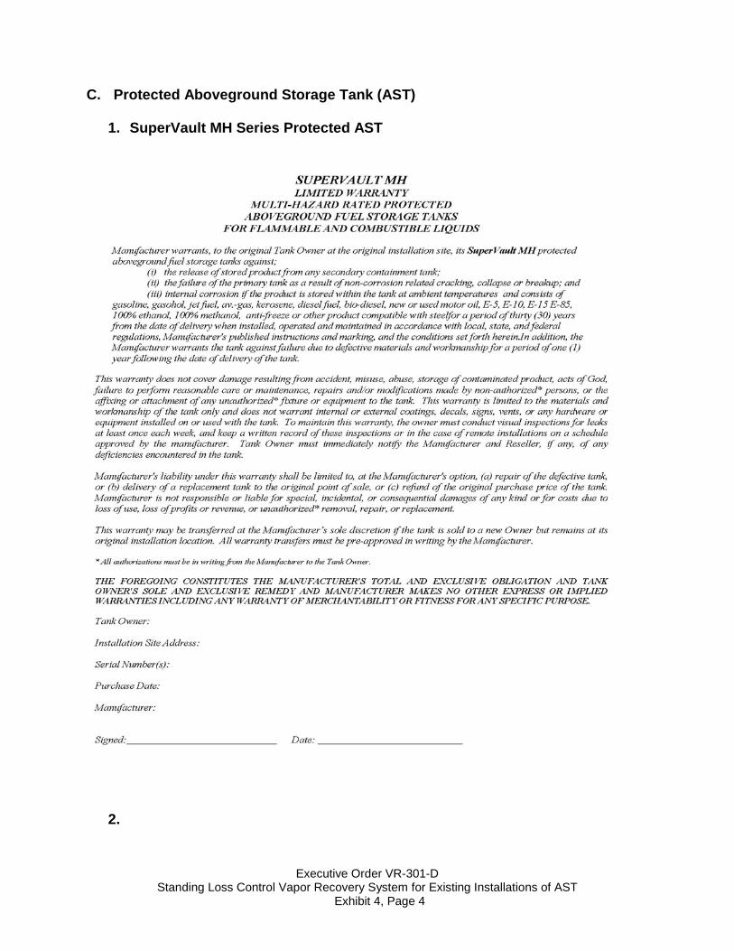
C. Protected Aboveground Storage Tank (AST)
1. SuperVault MH Series Protected AST
2.
Executive Order VR-301-D Standing Loss Control Vapor Recovery System for Existing Installations of AST
Exhibit 4, Page 5
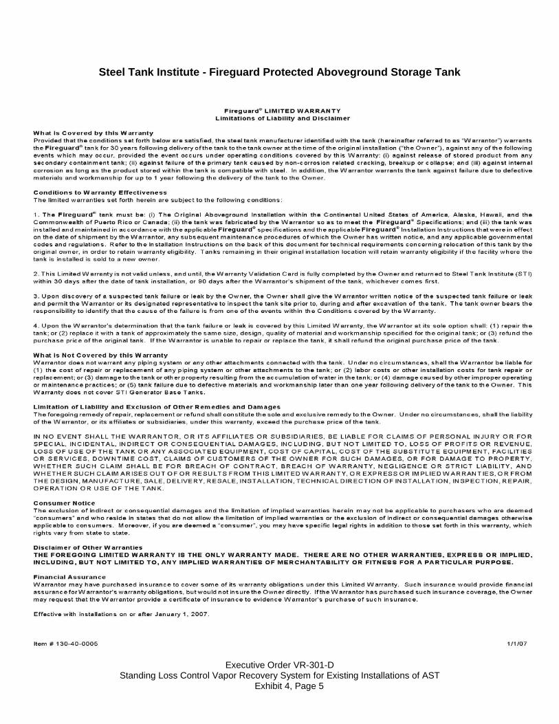
Steel Tank Institute - Fireguard Protected Aboveground Storage Tank
Executive Order VR-301-D Standing Loss Control Vapor Recovery System for Existing Installations of AST
Exhibit 4, Page 6
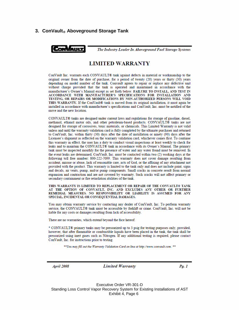
3. ConVault® Aboveground Storage Tank
Executive Order VR-301-D Standing Loss Control Vapor Recovery System for Existing Installations of AST
Exhibit 4, Page 7
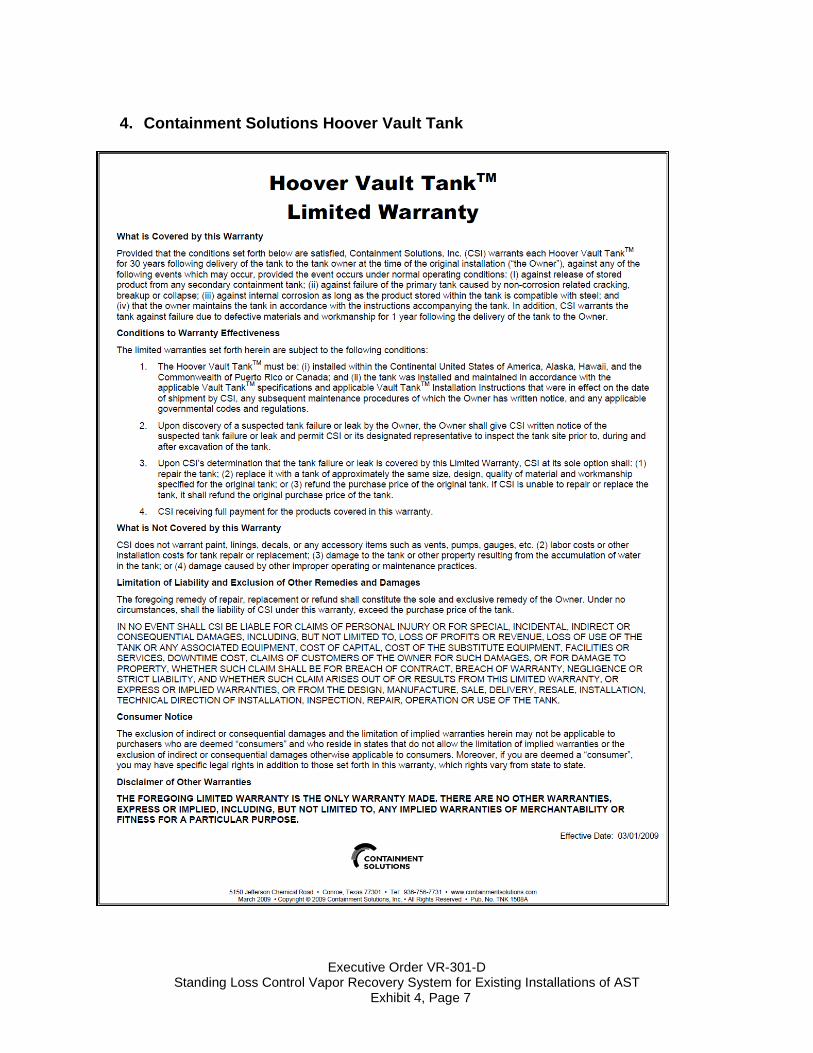
4. Containment Solutions Hoover Vault Tank
Executive Order VR-301-D Standing Loss Control Vapor Recovery System for Existing Installations of AST
Exhibit 4, Page 8
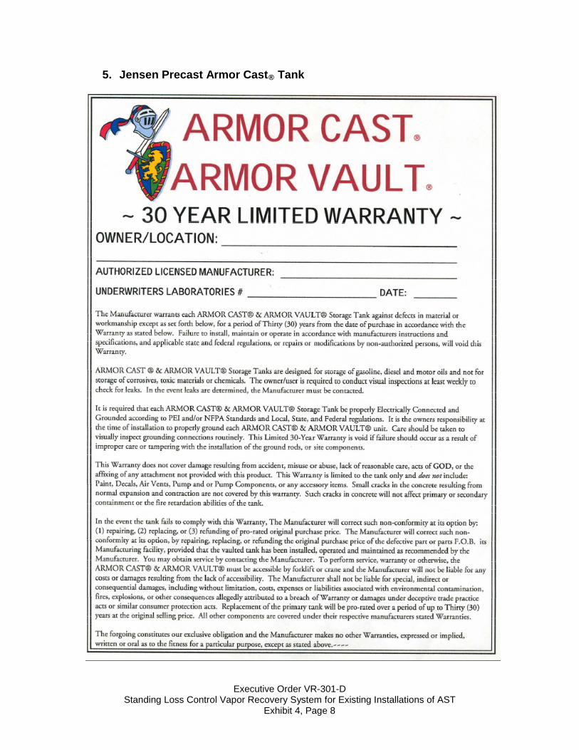
5. Jensen Precast Armor Cast® Tank