standard specifications town of dyer · standard specifications town of dyer ... reinforced...
TRANSCRIPT
Town of Dyer
GENERAL REQUIREMENTS AND COVENANTS 1
STANDARD SPECIFICATIONS
TOWN OF DYER
Section 100.0 – General Requirements and Covenants
The specifications contained herein shall be for the construction of the following public facilities
with the Town of Dyer:
A. Storm Sewer Construction Standards - Section 200.0
B. Sanitary Sewer Construction Standards - Section 300.0
C. Sewage Pumping Station Minimum Standards - Section 400.0
D. Water Distribution System Construction Standards - Section 500.0
E. Street Pavements, Curb & Gutter Construction Standards - Section 600.0
F. Sidewalk Standards - Section 700.0
G. Street Lighting Standards - Section 800.0
H. Storm Water Detention Standards - Section 900.0
I. Engineering Drawing Standards - Section 1000.0
J. Erosion and Sediment Control Standards – Section 1100.0
K. Standard Drawings – Section 1200.0
Unless specifically stated in the specifications, the following documents shall provide general
requirements and covenants applicable to construction within the Town of Dyer.
In the event of conflict between the contents of this document and the existing Town codes, the
former will supersede the latter and/or the written decision of the Director of Public Works or
Town Engineer (or their respective designee) will prevail.
All roadways shall be constructed in accordance with State of Indiana Department of
Transportation Standard Specifications latest revision.
Town of Dyer
STORM SEWER CONSTRUCTION STANDARDS 2
STORM SEWER CONSTRUCTION STANDARDS
Section 200.0 – General
The standards and requirements found in this article are for materials and constructing of storm
sewer systems within the Town of Dyer.
All storm water run-offs of a proposed development shall be collected and flow into the proposed
storm sewer system and storm water detention facility (as required) to minimize direct discharge
into the Town of Dyer’s streams, ditches and ponds as well as private water courses.
Construction methods that will minimize siltation, erosion and sediment shall be employed. The
design engineer shall include in the Primary and Final Engineering Plans, Section 1000, the
methods and practices to be employed in the construction of sewers in or near streams or provide
adequate control of siltation, erosion and sediment in accordance with the Town of Dyer Erosion
and Sediment Control Ordinance, Section 915.0 – Erosion and Sediment Control (Section 1100,
Erosion and Sediment Control Standards), IDEM requirements, Natural Resources Conservation
Service (NRCS).
IDEM Rule 13, Notice of Intent (NOI) in particular shall be adhered to.
Section 200.1 – Specifications
These specifications cover materials, construction and all appurtenances normally used for the
construction of a storm sewer system.
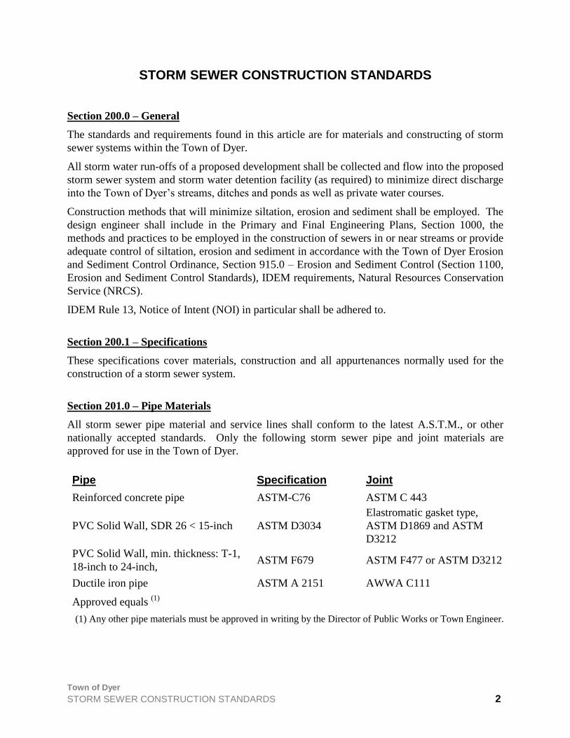
Section 201.0 – Pipe Materials
All storm sewer pipe material and service lines shall conform to the latest A.S.T.M., or other
nationally accepted standards. Only the following storm sewer pipe and joint materials are
approved for use in the Town of Dyer.
Pipe Specification Joint
Reinforced concrete pipe ASTM-C76 ASTM C 443
PVC Solid Wall, SDR 26 < 15-inch ASTM D3034
Elastromatic gasket type,
ASTM D1869 and ASTM
D3212
PVC Solid Wall, min. thickness: T-1,
18-inch to 24-inch, ASTM F679 ASTM F477 or ASTM D3212
Ductile iron pipe ASTM A 2151 AWWA C111
Approved equals (1)
(1) Any other pipe materials must be approved in writing by the Director of Public Works or Town Engineer.

Town of Dyer
STORM SEWER CONSTRUCTION STANDARDS 3
Section 202.0 – Design Calculations and Storm Sewer Plans
A) All design calculations and storm sewer plans shall be submitted and approved by the Dyer
Storm Water Management Board before any phase of the storm sewer construction begins.
B) All design calculations shall include sketch or map showing the drainage area at each point of
interception, which is labeled and coincides with the design calculation sheet.
C) All design calculations and plans must be signed and sealed by a Professional Engineer
licensed in the State of Indiana.
Section 203.0 – Design Criteria for Storm Sewers and Surface Swales
All storm water run-offs of a proposed development shall be collected and flow into the proposed
storm sewer system and storm water detention facility (as required) to minimize direct discharge
into the Town of Dyer’s streams, ditches and ponds as well as private water courses.
All storm sewers, whether public or private shall conform to the design standards and other
requirements herein.
Section 203.1 – Storm Sewer Design Standards
A) General
A ten year frequency storm, using the duration which produces the peak runoff shall be used
to design the storm drainage system. The Rational Method will be acceptable for storm sewer
design, as long as TR-55 time of concentration methodology is used.
A minimum drop of one-tenth of one foot (0.1’) through the manholes should be provided.
Runoff coefficients and inlet times are provided in Section 900.
Connections to sanitary sewers or existing agricultural drainage systems (tiles) will not be
permitted for new developments.
The use of slag material as backfill is not an acceptable alternative in the Town of Dyer
B) Minimum Size
The minimum storm sewer size shall be twelve inches (12”). Storm sewers shall be designed
to flow full, using Manning's Equation with a roughness coefficient of 0.013. If a storm
sewer is designed with a constantly submerged outfall, the sewer shall be designed using the
hydraulic profile with a maximum allowable water level elevation in manholes of one foot
zero inches (1'-0") below the flow line of the gutter.
C) Grade
Sewer grade shall be such that a minimum cover of three feet (3’) is maintained over the pipe
or greater if necessary to comply with the manufacturer’s recommendation. Uniform slopes
shall be maintained between structures. Final grade shall be set with full consideration of the
capacity required, sedimentation problems, and other design parameters. Minimum and
maximum allowable slopes shall be those capable of producing velocities of three feet per

Town of Dyer
STORM SEWER CONSTRUCTION STANDARDS 4
second (3 fps) and fifteen feet per second (15 fps), respectively when the sewer is flowing
full.
D) Alignment
Storm Sewers shall be straight between manholes. PVC pipe shall be installed with a
metallic tracer wire for future location purposes.
E) Manholes/ Catch Basins/ Inlets
1) All manholes, catch basins, inlet manholes and inlets, and headwalls shall be designed in
accordance with the standard details of the Town of Dyer.
2) Manholes shall be provided at the following locations:
i) Where two or more storm sewers converge.
ii) Where the pipe size changes.
iii) Where a change in grade occurs.
3) All inlets shall be installed so that the distance between each inlet shall not exceed three
hundred and fifty feet (350') and each inlet shall drain a maximum street gutter length of
three hundred and fifty feet (350').
4) Inlets to be located at all low points and intersections.
5) The inlet grate provided must be adequate to pass the design flow with fifty percent
(50%) of the sag inlet areas clogged.
6) Inlet design and spacing calculations shall be submitted with the drainage calculations
7) No more than two inlets shall be interconnected; a catch basin (structure with a sump)
shall be installed in line prior to discharge into a storm water manhole.
8) All residential lots shall be served with rear yard storm water drain lines and structures,
placed at a distance of three hundred feet (300’) or two (2) lots, which ever is less and
with use of a wye connection fitting. Residential services may be permitted to tie into
inlets or catch basins with use of a rubber pipe boot.
9) All roadway inlets and catch basins shall have three six-inch (6") perforated finger drains:
one located a minimum length of fifteen feet (15') across the roadway and two located a
minimum of fifty feet (50') along the curb line, in opposite directions.
10) An overload channel from sag inlets to the overflow channel or basin shall be provided at
sag inlets, so that the maximum depth of water ponding in the street is seven inches (7”).
11) An environmental stamp is required on all curb inlets, catch basins, manhole covers and
any other storm sewer lids or castings in all new developments. Examples of permissible
stamps include: “No Dumping – Drains to Stream”, “Dump No Waste”, Trout Logo, etc.
F) Overland Flow
1) The storm system shall be designed with “positive street and swale drainage” such that in
the event of a complete storm system failure, storm water runoff will be provided
Town of Dyer
STORM SEWER CONSTRUCTION STANDARDS 5
overland to the storm water detention area and will cause no property damage due to
flooding.
2) All areas of the developed property must be provided with an overland flow path that will
pass the 100-year flow at a stage at least two feet (2') below foundation grades in the
vicinity of the flow path. Overland flow paths designed to handle flows in excess of the
minor drainage system capacity shall be provided in drainage easements. Street ponding
and flow depths shall not exceed seven inches (7''). Ponding in the rear yards shall not
exceed one foot (1').
G) Separation
1) Connections to sanitary sewers or existing agricultural drainage systems (tiles) will not be
permitted for new developments. All developments will utilize separate drainage systems
to avoid disruption of overloading of the existing agricultural tile drainage system. Any
existing field tile systems cut during the process of land development must be
reconnected to provide for continuous flow and the location noted on the "as-built"
drawings.
2) Refer to Section 502 Protection of Water Main for separation requirements between
storm sewers and water mains.
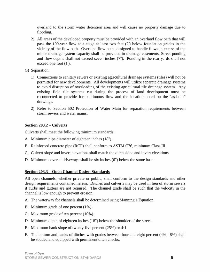
Section 203.2 – Culverts
Culverts shall meet the following minimum standards:
A. Minimum pipe diameter of eighteen inches (18'').
B. Reinforced concrete pipe (RCP) shall conform to ASTM C76, minimum Class III.
C. Culvert slope and invert elevations shall match the ditch slope and invert elevations.
D. Minimum cover at driveways shall be six inches (6") below the stone base.
Section 203.3 – Open Channel Design Standards
All open channels, whether private or public, shall conform to the design standards and other
design requirements contained herein. Ditches and culverts may be used in lieu of storm sewers
if curbs and gutters are not required. The channel grade shall be such that the velocity in the
channel is low enough to prevent erosion.
A. The waterway for channels shall be determined using Manning’s Equation.
B. Minimum grade of one percent (1%).
C. Maximum grade of ten percent (10%).
D. Minimum depth of eighteen inches (18") below the shoulder of the street.
E. Maximum bank slope of twenty-five percent (25%) or 4:1.
F. The bottom and banks of ditches with grades between four and eight percent (4% - 8%) shall
be sodded and equipped with permanent ditch checks.

Town of Dyer
STORM SEWER CONSTRUCTION STANDARDS 6
Minimum velocity of one foot, five inches per second (1.42 fps) should be avoided since
siltation will take place and ultimately reduce the channel cross-section.
The maximum permissible velocities in vegetal-lined channel shall be designed in
accordance with the Soil Conservation Service (SCS) SCS-TP-61, Handbook of Channel
Design for Soil and Water Conservation. Calculations are required to show the stability of
the proposed channel and the maximum velocity must not exceed five feet per second (5 fps)
unless approved in writing by Director of Public Works or Town Engineer
G. The bottom and banks of ditches with grades between eight and ten percent (8% - 10%) shall
be paved with concrete riprap.
Section 203.4 – Channel Stability
The channel shall be designed with the characteristics of a stable channel, which are:
1) The channel neither aggrades nor degrades beyond tolerable limits.
2) The channel banks do not erode to the extent that the channel cross section is changed
appreciably.
3) Excessive sediment bars do not develop.
4) Excessive erosion does not occur.
5) Gullies do not form or enlarge due to the entry of uncontrolled surface flow to the
channel.
Section 204.0 – Erosion and Sediment Control
Erosion Control Plans shall be submitted as part of the Primary and Final Engineering Plans. See
Section 1100, Erosion and Sediment Control Standards for complete requirements.
Section 205.0 - Cleaning and Televising of Storm Sewers
The Town of Dyer Public Works Department shall perform cleaning and televising of storm
sewers. A fee, charged to the developer, has been established for this service in the Dyer Town
Code at section 10-119.
Town of Dyer
SANITARY SEWER CONSTRUCTION STANDARDS 7
SANITARY SEWER CONSTRUCTION STANDARDS
Section 300.0 – General
All developments, regardless of size within the corporate limits or otherwise within the
jurisdiction of the Town, shall include provisions for the construction of sanitary sewerage
facilities, designed in accordance with the latest revision Indiana Administrative Code at 327
IAC 3. This rule includes minimum administrative requirements for obtaining a construction
permit as well as technical standards for the design and installation of sanitary sewers.
Sanitary sewers shall be constructed throughout a development allowing for the extension of the
Town sewer system to adjacent areas.
The design of all sanitary sewerage facilities proposed for construction or reconstruction as
independent projects under Town jurisdiction shall also meet the technical requirements of this
section.
The Service Area shall include the entire area proposed to be ultimately served by all or a portion
of the sanitary sewer system submitted for approval.
Section 300.1 – Specifications
These specifications cover pipe for sanitary sewer mains and sanitary sewer service connections,
sewer fittings, manholes and all appurtenances normally used for sanitary sewer collection
systems. Special considerations will be covered in the detailed plans and special provisions
covering the proposed construction.
Section 300.2 – Regulations
Additional rules and regulations governing sanitary sewer construction in the Town of Dyer are:
A. The restrictions, policies, and instructions that may be adopted or issued from time to time by
the Town of Dyer, Dyer Sanitary Board; and
B. The Indiana Department of Environmental Management (IDEM).
Section 300.3 – Sanitary Sewers
All sanitary sewage consisting of domestic and other water-borne wastes shall be collected and
conveyed in a sanitary sewer pipe system to a point of discharge into an existing sanitary sewer
system. No sanitary sewage shall be allowed to enter any storm sewer system or discharged onto
the ground or into receiving streams without first being treated.
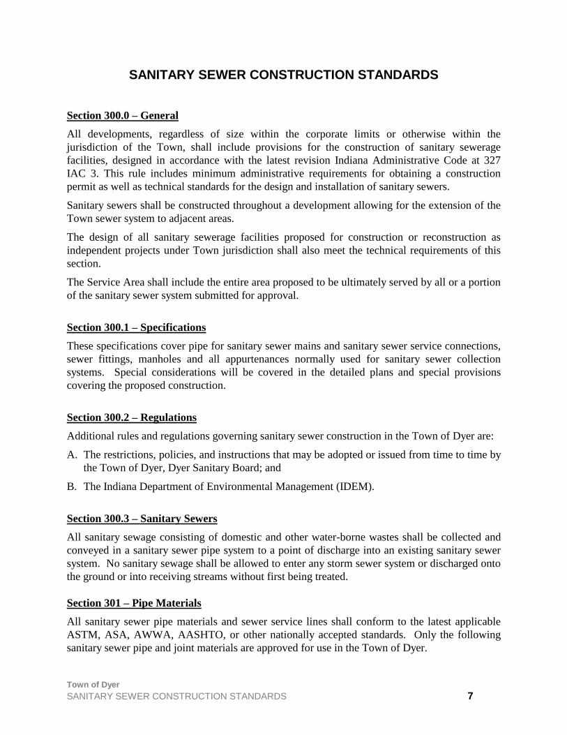
Section 301 – Pipe Materials
All sanitary sewer pipe materials and sewer service lines shall conform to the latest applicable
ASTM, ASA, AWWA, AASHTO, or other nationally accepted standards. Only the following
sanitary sewer pipe and joint materials are approved for use in the Town of Dyer.
Town of Dyer
SANITARY SEWER CONSTRUCITON STANDARDS 8
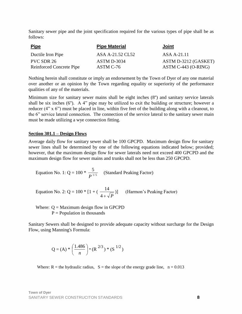
Sanitary sewer pipe and the joint specification required for the various types of pipe shall be as
follows:
Pipe Pipe Material Joint
Ductile Iron Pipe ASA A-21.52 CL52 ASA A-21.11
PVC SDR 26 ASTM D-3034 ASTM D-3212 (GASKET)
Reinforced Concrete Pipe ASTM C-76 ASTM C-443 (O-RING)
Nothing herein shall constitute or imply an endorsement by the Town of Dyer of any one material
over another or an opinion by the Town regarding equality or superiority of the performance
qualities of any of the materials.
Minimum size for sanitary sewer mains shall be eight inches (8'') and sanitary service laterals
shall be six inches (6''). A 4” pipe may be utilized to exit the building or structure; however a
reducer (4” x 6”) must be placed in line, within five feet of the building along with a cleanout, to
the 6” service lateral connection. The connection of the service lateral to the sanitary sewer main
must be made utilizing a wye connection fitting.
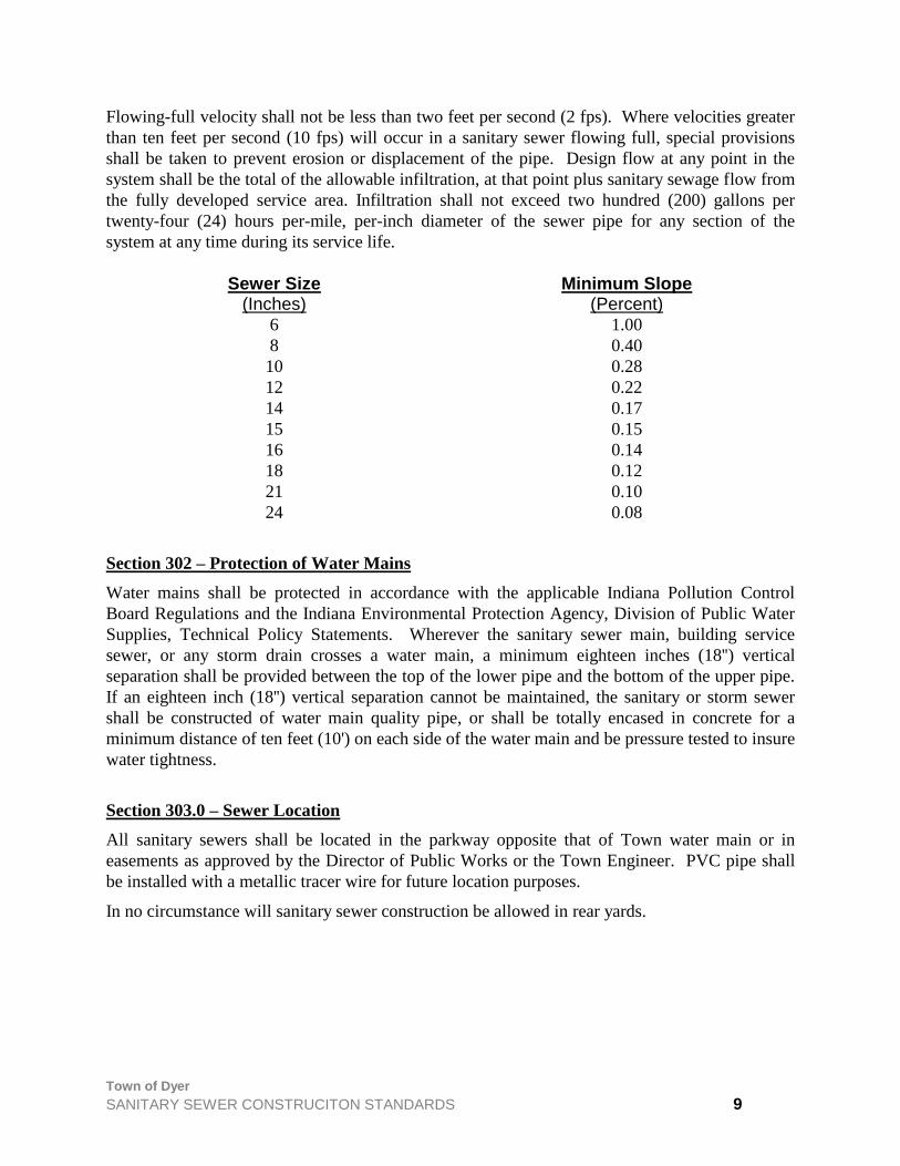
Section 301.1 – Design Flows
Average daily flow for sanitary sewer shall be 100 GPCPD. Maximum design flow for sanitary
sewer lines shall be determined by one of the following equations indicated below; provided;
however, that the maximum design flow for sewer laterals need not exceed 400 GPCPD and the
maximum design flow for sewer mains and trunks shall not be less than 250 GPCPD.
Equation No. 1: Q = 100 * 5/1
5
P(Standard Peaking Factor)
Equation No. 2: Q = 100 * [1 + ( P4
14)] (Harmon’s Peaking Factor)
Where: Q = Maximum design flow in GPCPD
P = Population in thousands
Sanitary Sewers shall be designed to provide adequate capacity without surcharge for the Design
Flow, using Manning's Formula:
Q = (A) *
n
486.1 * (R
2/3 ) * (S
1/2 )
Where: R = the hydraulic radius, S = the slope of the energy grade line, n = 0.013
Town of Dyer
SANITARY SEWER CONSTRUCITON STANDARDS 9
Flowing-full velocity shall not be less than two feet per second (2 fps). Where velocities greater
than ten feet per second (10 fps) will occur in a sanitary sewer flowing full, special provisions
shall be taken to prevent erosion or displacement of the pipe. Design flow at any point in the
system shall be the total of the allowable infiltration, at that point plus sanitary sewage flow from
the fully developed service area. Infiltration shall not exceed two hundred (200) gallons per
twenty-four (24) hours per-mile, per-inch diameter of the sewer pipe for any section of the
system at any time during its service life.
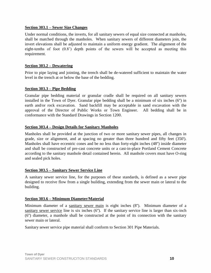
Sewer Size (Inches)
Minimum Slope (Percent)
6 1.00
8 0.40
10 0.28
12 0.22
14 0.17
15 0.15
16 0.14
18 0.12
21 0.10
24 0.08
Section 302 – Protection of Water Mains
Water mains shall be protected in accordance with the applicable Indiana Pollution Control
Board Regulations and the Indiana Environmental Protection Agency, Division of Public Water
Supplies, Technical Policy Statements. Wherever the sanitary sewer main, building service
sewer, or any storm drain crosses a water main, a minimum eighteen inches (18'') vertical
separation shall be provided between the top of the lower pipe and the bottom of the upper pipe.
If an eighteen inch (18'') vertical separation cannot be maintained, the sanitary or storm sewer
shall be constructed of water main quality pipe, or shall be totally encased in concrete for a
minimum distance of ten feet (10') on each side of the water main and be pressure tested to insure
water tightness.
Section 303.0 – Sewer Location
All sanitary sewers shall be located in the parkway opposite that of Town water main or in
easements as approved by the Director of Public Works or the Town Engineer. PVC pipe shall
be installed with a metallic tracer wire for future location purposes.
In no circumstance will sanitary sewer construction be allowed in rear yards.
Town of Dyer
SANITARY SEWER CONSTRUCITON STANDARDS 10
Section 303.1 – Sewer Size Changes
Under normal conditions, the inverts, for all sanitary sewers of equal size connected at manholes,
shall be matched through the manholes. When sanitary sewers of different diameters join, the
invert elevations shall be adjusted to maintain a uniform energy gradient. The alignment of the
eight-tenths of foot (0.8’) depth points of the sewers will be accepted as meeting this
requirement.
Section 303.2 – Dewatering
Prior to pipe laying and jointing, the trench shall be de-watered sufficient to maintain the water
level in the trench at or below the base of the bedding.
Section 303.3 – Pipe Bedding
Granular pipe bedding material or granular cradle shall be required on all sanitary sewers
installed in the Town of Dyer. Granular pipe bedding shall be a minimum of six inches (6'') in
earth and/or rock excavation. Sand backfill may be acceptable in sand excavation with the
approval of the Director of Public Works or Town Engineer. All bedding shall be in
conformance with the Standard Drawings in Section 1200.
Section 303.4 – Design Details for Sanitary Manholes
Manholes shall be provided at the junction of two or more sanitary sewer pipes, all changes in
grade, size or alignment, and at spacing no greater than three hundred and fifty feet (350').
Manholes shall have eccentric cones and be no less than forty-eight inches (48'') inside diameter
and shall be constructed of pre-cast concrete units or a cast-in-place Portland Cement Concrete
according to the sanitary manhole detail contained herein. All manhole covers must have O-ring
and sealed pick holes.
Section 303.5 – Sanitary Sewer Service Line
A sanitary sewer service line, for the purposes of these standards, is defined as a sewer pipe
designed to receive flow from a single building, extending from the sewer main or lateral to the
building.
Section 303.6 – Minimum Diameter/Material
Minimum diameter of a sanitary sewer main is eight inches (8''). Minimum diameter of a
sanitary sewer service line is six inches (6''). If the sanitary service line is larger than six-inch
(6'') diameter, a manhole shall be constructed at the point of its connection with the sanitary
sewer main or lateral.
Sanitary sewer service pipe material shall conform to Section 301 Pipe Materials.

Town of Dyer
SANITARY SEWER CONSTRUCITON STANDARDS 11
Section 303.7 – Sanitary Sewer Design Standards
Capacity requirements and design details for sanitary sewers shall apply to sanitary sewer service
lines, except the minimum slope shall be 1/8-inch per foot or one percent (1%).
The use of slag material as backfill is not an acceptable alternative in the Town of Dyer.
Section 303.8 – Plugs
In those instances when the service line is not immediately connected to the building to be
serviced, it shall be tight plugged using a manufactured plug to hold it firmly in place.
Section 303.9 – Sanitary Sewer Service Line Connections
Sanitary sewer services shall be extended to the property line. Sanitary sewer service connections
to sewer mains twelve feet (12') or more in depth shall be constructed with a six inch (6'') tee and
riser and backfilled with select granular material. On a temporary basis, sanitary services may be
terminated with a manufactured plug in which case the location shall be staked and an accurate
record kept of the distance from the nearest downstream manhole along the sewer main.
When Sanitary Sewer Service Lines are constructed as part of the same project as the sewer main
or lateral, they shall be connected to the sewer main or lateral using a wye. Where a Sanitary
Sewer Service Line is to connect to an existing sewer main or lateral, or where specific approval
has been granted by the Director of Public Works or the Town Engineer for the construction of a
service line after the completion of the sewer main or lateral, the connection shall be made by
one of the methods detailed below:
A. Installation of a manhole.
B. Circular saw-cut of sewer main by proper tools, and proper installation of a hub wye saddle
or a hub tee saddle, in accordance with manufacturer's recommendations.
C. Using pipe cutter, neatly and accurately cut out desired length of pipe for insertion of proper
fittings. Use "Band-Seal" couplings, or similar couplings, and shear rings and clamps to
fasten the inserted fitting and hold it firmly in place. Follow manufacturer's
recommendations for the installation. Cement joints are prohibited.
D. Residential services are not permitted to tie into manholes.
Risers shall be required for services where sewers are over twelve feet (12') deep and shall extend
within eight feet (8') of finished grade as a minimum.
Section 303.10 – Depth of Pipe Cover
All pipe shall be laid to a radial minimum depth of five feet (5') measured from the existing or
proposed ground surface to the outer edge of the pipe barrel unless specifically allowed
otherwise, in special circumstances by the Director of Public Works or the Town Engineer.
Town of Dyer
SANITARY SEWER CONSTRUCITON STANDARDS 12
Section 303.30 – Location of Sewers on Streams
A. Cover Depth
The top of all sewers entering or crossing streams shall be at a sufficient depth below the
natural bottom of the stream bed to protect the sewer line. In general, the following cover
requirements must be met:
1. One foot of cover is required where the sewer is located in rock.
2. Three feet of cover is required in other material. In major streams more than three feet of
cover may be required.
3. In paved stream channels, the top of the sewer line should be placed below the bottom of
the channel pavement.
Note: Less cover will be approved only if the proposed sewer crossing will not interfere with
the future improvements to the channel stream.
B. Horizontal Location
Sewers located along streams shall be located outside of the stream bed and sufficiently
removed from there to provide for future possible stream widening and to prevent pollution
by siltation during construction.
C. Structures
The Sewer outfalls, headwalls, manholes, gate boxes, or other structures shall be located so
they do not interfere with the free discharge of flood flows of the stream.
D. Alignment
Sewers crossing streams should be designed to cross the stream as nearly perpendicular to the
stream flow as possible and shall be designed without change in grade. Sewer systems shall
be designed to minimize the number of stream crossings.
Section 303.40 – Construction Requirements
A. Materials and Backfill
Sewers entering or crossing streams shall be constructed of ductile iron pipe with mechanical
joints and shall be constructed to remain watertight, free from changes in alignment and
grade, and prevented from floating.
The backfill used in the trench shall be coarse aggregate, gravel, or other materials which will
not cause siltation, pipe damage during placement or chemical corrosion in place.
Section 303.41 – Erosion and Sediment Control
Erosion Control Plans shall be submitted as part of the Primary and Final Engineering Plans. See
Section 1100, Erosion and Sediment Control Standards for complete requirements.

Town of Dyer
SANITARY SEWER CONSTRUCITON STANDARDS 13
Section 303.50 – Aerial Crossings
A. Structural Support
Support for all joints shall be provided in pipes utilized in aerial crossings. The supports
shall be designed to prevent frost heave, overturning and settlement.
B. Freeze and Expansion Protection
Protection against freezing shall be provided. This may be accomplished through the use of
insulation and increased slope expansion jointing shall be provided between the aerial and
buried sections of the sewer line.
C. Flood Clearance
For aerial stream crossings the impact of floodwaters and debris shall be considered. The
bottom of the pipe should be placed no lower than the elevation of the 100-year flood.
Section 303.60 – Inverted Siphons
A. Requirements
Inverted siphons shall have not less than two barrels with a minimum pipe size of six inches
(6'') and shall be provided with the necessary appurtenances for convenient flushing and
maintenance; the inlet and outlet structures shall have adequate clearance for cleaning; and in
general, sufficient head shall be provided and pipe sizes selected to secure velocities at least
three feet per second (3 fps) for average flows. The inlet and outlet structures shall be
designed so that normal flow is diverted to one barrel so that either barrel may be taken out of
service for cleaning.
Section 304.0 – Handling of Pipe
Sanitary sewer pipe shall be handled in a manner that will prevent damage. Damaged or
defective material on the job site shall be rejected and replaced to the satisfaction of the Director
of Public Works or Town Engineer. Methods of construction conducive to the damage of sewer
pipe shall be avoided and corrected when called to the attention of the contractor. All pipe and
fittings shall be examined by the contractor above grade before placement in the trench.
Section 305.0 – Laying of Pipe
Sanitary sewer pipe shall be laid true to line and grade. Dirt or other foreign material shall be
prevented from entering the pipe or pipe joint during handling or laying operations and any pipe
or fitting that has been installed with dirt or foreign material in it shall be removed, cleaned, and
re-laid.
At times when pipe laying is not in progress, the open end of the pipe shall be closed with a
watertight plug or by other means approved by the Director of Public Works or Town Engineer
to ensure absolute cleanliness inside the pipe.

Town of Dyer
SANITARY SEWER CONSTRUCITON STANDARDS 14
Section 305.1 – Laying of Pipe Curves
The curvature of sanitary sewers is not allowed unless, in the opinion of the Director of Public
Works or Town Engineer, special circumstances dictate otherwise. Pipe required to be laid on
curved alignment shall be joined in straight alignment and then deflected, joint by joint. Special
care shall be taken in blocking the pipe and in no case shall the degree of deflection exceed
manufacturer's recommendations for the respective pipe size, material and barrel length.
Section 305.2 – Sanitary Sewer Service
Moved to Section 303.9 – Sanitary Sewer Service Line Connections
Section 306.0 – Sanitary Sewer Manholes
Consolidated into Section 303.4– Design Details for Sanitary Manholes
Section 306.1 – Manhole Location
Consolidated into Section 303.4– Design Details for Sanitary Manholes
Section 306.2 – Construction
Sanitary manholes shall have poured-in-place or pre-cast inverts made to conform accurately to
the sewer grades with smooth, well rounded junctions and transitions satisfactory to the Director
of Public Works or Town Engineer.
If the invert is to be poured in place, the sanitary sewer pipe shall be extended through the
manhole, the concrete poured and formed, and the pipe then broken or sawed out through the
manhole. The sewer pipe to manhole connection joint shall have a flexible gasket or mechanical
seal to insure a leak-proof joint. The completed manhole shall be in rigid, true to dimensions,
and water tight.
Chimney seals and pipe boots are required on all sanitary manholes.
Section 306.3 – Manhole Appurtenances
Manholes shall be furnished with a watertight frame and solid cover (Neenah Foundry, East
Jordan Iron Works 1020 HD, or approved equal) with the words, "Sanitary Sewer" imprinted on
the cover in raised letters. Both the manhole frame and cover shall have machined horizontal and
vertical bearing surfaces. Manholes located in areas subject to inundation shall be furnished with
waterproof bolt-down frames and covers (Neenah Foundry, East Jordan Iron Works, or approved
equal).
Pick holes shall not create openings in the manhole cover.
Manhole frames shall be adjusted to proper grade utilizing reinforced pre-cast concrete rings;
brick or concrete blocks will not be allowed. Adjusting rings shall be securely sealed to the cone
section or top barrel section of the manhole using resilient, flexible, non-hardening, pre-formed,
bituminous rope mastic material. This mastic shall be applied in such a manner that no surface
Town of Dyer
SANITARY SEWER CONSTRUCITON STANDARDS 15
water inflow can enter the manhole through gaps between the top barrel section or cone section
and the first adjusting ring, between adjusting rings, or between the last ring, adjusting ring and
manhole frame. Up to twelve inches (12") of adjusting rings may be installed on a given
manhole; however, no more than three rings shall be used.
Rubber coated manhole steps on maximum of sixteen inch (16") centers shall be furnished with
each manhole securely anchored in place true to vertical alignment, in accordance with the Dyer
Standard.
Chimney seals and pipe boots are required on all sanitary manholes.
All sanitary manholes shall be designed with provisions for sewer pipe to be continued through
manholes by means of standard fittings (i.e. bends, wyes, tees).
Inverts shall be concrete poured around pipe and/or fittings and sloped from edge of manhole to
centerline of pipe or fittings. The top of the pipe of fitting shall then be removed in a manner
that provides smooth transition through manholes. Manholes with pre-cast inverts may be used
with prior approval from the Director of Public Works or Town Engineer.
Section 306.4 – Inspection Manholes
All non-residential and other establishments that are covered under the Town of Dyer Pre-
Treatment Ordinance (Town Code Section 9-104) shall be required to construct an inspection
manhole. The inspection manhole shall conform to the Town of Dyer Standard Detail.
Section 306.5 – Drop Manhole Assemblies
Drop manhole assemblies shall be provided at the junction of sanitary sewers where the
difference in a grade exceeds two feet (2'). The entire drop assembly shall be cast in concrete
monolithically with the manhole barrel section and shall follow the Town of Dyer Standard
Detail.
Section 306.6 – Inspection of Manholes
All manholes shall be thoroughly cleaned of dirt and debris and be grouted at all joints. All
visible leakage must be eliminated before final inspection and acceptance by the Town of Dyer.
Section 307 – Testing for Acceptance of Sanitary Sewers
All sanitary sewers twenty-one inches (21") and smaller, including service lines, and manholes
shall pass a low-pressure air test before acceptance. In addition, the Director of Public Works
may, at his discretion, require an exfiltration test as described in Section 307.2 prior to final
acceptance. Sanitary sewers twenty-four inches (24") and larger shall pass an exfiltration test
described in Section 307.2 and be subject to a physical inspection by the Director of Public
Works. In addition to the above, manholes are subject to physical inspection. Mandrel testing of
plastic pipe will be required.
Force mains shall be tested for leakage after installation and prior to final acceptance, in
accordance with AWWA standards for testing pressure pipe (ASTM E103). The test line shall

Town of Dyer
SANITARY SEWER CONSTRUCITON STANDARDS 16
be pressurized to one and one half (1.5) times the pump shut-off head as determined from the
pump manufacturer’s performance curves or to one hundred pounds per square inch (100 psi)
whichever is greater.
The Town of Dyer Public Works Department shall perform cleaning and televising of sanitary
sewers. A fee, charged to the developer, has been established for this service in the Dyer Town
Code, Section 10-119.
Section 307.1 – Low Pressure Air Test Procedures and Requirements
The procedure for low pressure air testing shall follow that set forth. The air test shall, as a
minimum, conform to the test procedure described in ASTM C 924 for concrete pipe, ASTM F
1417 for PVC pipe. All plugs, including those in sanitary services, must be carefully braced to
prevent leakage and blowout.
Section 307.2 – Exfiltration Test Procedures and Requirements
The exfiltration test shall be performed in the absence of ground water in accordance with the
following procedure:
A. Plug the upper and lower section of sewer main to be tested;
B. Fill the line and all manholes with water to a depth of four feet (4') above the invert of the
mid-point of the section being tested;
C. Let the water stand in the section of sewer main being tested for a period of twenty-four (24)
hours to allow for absorption and escape of trapped air;
D. After a period of twenty-four (24) hours has elapsed, refill the section to original depth; and
E. After an additional one-hour period has elapsed, refill the line again to original depth,
recording the total amount of water necessary (measured in gallons) for refill.
The amount of exfiltration shall not exceed two hundred (200) gallon per inch of pipe diameter
per mile per day, including all manholes and service lines. The decision of the Director of Public
Works or Town Engineer shall be final in determining the results.
Section 307.3 – Test Results
If the sanitary sewer installation fails to meet the test requirements specified, the contractor shall
determine the cause or causes of the defect and shall, at his own expense repair or replace all
materials and workmanship as may be necessary to comply with the test requirements.
Section 308.0 – Footing Tiles
Footing tiles, perimeter tiles, downspouts, roof drains, or any other pipes, which drain
groundwater, subsurface water, or surface runoff water shall not be connected to the sanitary
sewer system.

Town of Dyer
SANITARY SEWER CONSTRUCITON STANDARDS 17
Section 309.0 – Grease, Oil and Sand Interceptors
A. Commercial and Industrial Facilities: A manhole is required for all commercial and industrial
facilities. The manhole shall be located on the service line, so samples may be taken before such
fluids reach the main line. Sand and grease traps, of suitable size and construction, shall be
required at any facility likely to introduce sand or grease products into the sewer system. This
includes all filling/gas stations, automotive repair garages, car washes, restaurants, and similar
places that may have wash or grease racks connected with the sewer utility.
Section 310.0 – Certification
It shall be the responsibility of the pipe manufacturers' to certify that pipe and joint materials
furnished are capable of meeting the low pressure air test, infiltration test, and exfiltration test
and are manufactured in conformance with the ASTM, ANSI, AWWA, or AASHTO test(s)
specified.

Town of Dyer
MINIMUM STANDARDS SEWAGE PUMPING STATIONS 18
SEWAGE PUMPING STATIONS MINIMUM STANDARDS
Section 400.0 – General
All sewage pumping stations, or lift stations which are now or may in the future be connected to
Town of Dyer collection and Treatment System must be approved by the State of Indiana
Department of Environmental Management (IDEM) and further reviewed by the Town of Dyer
Public Works Department, approved and conforming to the following additional Minimum
Standards as established by the Town of Dyer, Indiana.
Section 400.1 – Location
This facility must be located in such a manner that it is accessible by means of a paved street,
alley, or other public right-of-way. It should be visible to the residents of the Neighborhood, but
should not be obtrusive or unsightly, or be detrimental to the area. If so specified, the facility
shall be screened with trees, shrubs, bushes, or wooden fencing.
The site of the facility shall have a minimum of 1,200 square feet (30 x 40), and, unless
otherwise specified, shall be contained in a fenced area. The fence shall be six feet (6') high with
three barbed wires attached to the outriggers. The fenced area shall include a twelve-foot (12')
vehicle gate, and a three-foot (3') pedestrian gate.
A concrete paved parking area shall be provided with room for parking two vehicles. This paved
area must be connected to the adjacent paved roads.
The site must be graded to provide suitable drainage of the area and must be surfaced on the
traveled areas, with erosion control being provided on the other areas. The site must be at least
two feet (2') above the 100-Year Flood Elevation, which has been established by the Indiana
Department of Natural Resources.
The station shall be provided with suitable ballast to prevent floatation in the event of high water
around the area. This ballast shall be in addition to the "tie-down" bolts.
Section 400.2 – Type of Station
Flow Equipment Specifications 0 – 80 GPM Submersible Grinder Pumps See Attached for Details
80 – 300 GPM Wet Well Mount Design See Attached for Details
300 – 10,000 GPM Wet Pit/Dry Pit Design See Attached for Details
All lift stations built in the Town of Dyer must include permanent standby generators, with
exterior lighting for station (twenty feet (20') aluminum pole with sodium lamp). See attached
details.
No deviation from these standards will be accepted unless first discussed with the Town of Dyer
Public Works Department and written approval to revise is given.
Town of Dyer
MINIMUM STANDARDS SEWAGE PUMPING STATIONS 19
Section 400.3 – Specifications
The Town of Dyer has standardized on the following basic lift station design specifications for
the purposes of stocking parts and general operation and maintenance procedures.
Section 401.0 – Submersible Grinder Pump Station
0 to 80 GPM
Section 402.0 – Submersible Grinder Pumping Station Specification
Section 402.1 - General
The contractor shall furnish one automatic duplex submersible pump station with all needed
equipment installed in a concrete pump chamber with separate valve vault. The principal items
of equipment shall include but not be limited to; three submersible grinder sewage pumps, slide
away couplings, guide rail system, valves, piping, control panel, and generator as specified herein
and shown on the plan drawings. Two pumps shall be installed and the third pump shall be
supplied as a back-up unit.
Section 402.2 - Pump Chamber
The equipment chamber shall be fabricated of minimum six-inch (6'') thick pre-cast concrete to
form a cylinder, sixty inches (60") I.D. The top of the chamber shall include an aluminum access
cover with suitable lifting handle and locking hasp.
Watertight joint wall sleeves shall be provided where the joints are made to the inlet and
discharge lines. The joint shall also be designed to absorb any vibration, distortion, and normal
settling and maintain a leak proof seal.
A valve chamber shall be furnished separate from the pump chamber. The valve chamber shall
be of the same diameter as the wet well. The valve chamber shall be fabricated of minimum six-
inch pre-cast concrete. The top of the chamber shall include an aluminum access cover with
suitable lifting handle and locking hasp. The valve vault shall provide complete isolation from
the sewage wet well. A 1/3 HP, 160/115 VAC submersible sump pump with 1-1/4" discharge
shall be provided within the valve vault to remove any water back to the wet well. The discharge
line shall include a check valve to prevent any water or sewer gases from backing up into the
valve vault. The floor of the valve vault shall be pitched as shown on the plan drawings to drain
any entrained water to the sump pump. A fifteen (15) AMP circuit breaker shall be provided
within the pump station control panel to provide service for the sump pump.
Section 402.3 – Pump Construction
Each pump shall be designed as a completely submersible grinder pump capable of pumping raw
unscreened domestic sewage consisting of water, fibrous material, heavy sludge and spherical
solids of up to three inches (3") in diameter. All major pump parts shall be ASTM Class 30 cast
iron or better finished with an epoxy paint system.

Town of Dyer
MINIMUM STANDARDS SEWAGE PUMPING STATIONS 20
All nuts, bolts, and miscellaneous hardware in contact with the pumped material shall be 300
series stainless steel. All gaskets shall be of the compression square ring type eliminating critical
slip fits and the possibility of damage during assembly and disassembly associated with sliding
"O" ring seal arrangements.
The pump shall be a Barnes sewage grinder pump meeting the specific site operating conditions.
The pump impeller shall be of the recessed vortex design with twelve vanes. The impeller shall
be of 85-5-5-5 bronze construction and machined for threading to the motor shaft. The impeller
shall be capable of being trimmed to meet the specific performance characteristics required.
The grinder mechanism shall consist of a radial cutter threaded and locked on the motor shaft by
a countersunk washer in conjunction with a flat cap screw; and a shredding ring containing a
minimum of twenty-five flow passages with cutting edges. The shredding ring shall be
reversible to provide twice the cutting edge life. Both components shall be constructed of 440C
stainless steel hardened to Rockwell C55 and shall be finish ground for a fine cutting edge.
The double mechanical shaft seal shall be of the single spring design operating in an oil filled
seal cavity. Pump out vanes on the back of the impeller shroud shall develop a radially
increasing pressure differential from the impeller hub outward.
This pressure shall be transmitted by means of a rubber diaphragm to the oil in the seal cavity
thus producing a higher pressure inside the seal cavity than immediately adjacent to the seal face
in the pump case forcing the oil in the seal cavity to be the seal face lubricant. This arrangement
shall allow the pump to run dry for extended periods without damage to the seal faces. Seal faces
between the pump case and seal cavity shall be glass filled Teflon and ceramic.
Moisture within the seal cavity shall be detected with monitors and transmit a warning to alarm
lights in the control panel and shut the pump down.
The pump motor shall be the standard product of an established American motor manufacturer.
The pump motor shaft shall be ball bearing supported solid stainless steel. The pump motor shall
be designed to be non-overloading over the entire pump impeller trim curve. The motor shall be
secured in place by standard threaded fasteners and shall require only simple hand tools for
removal or replacement. Shrink fit motor assemblies shall not be acceptable. The motor housing
shall be oil filled or provided with other means to prevent overheating while running in a totally,
partially or non-submerged condition for extended periods. Motor windings shall be Class F
insulated. Lead wires shall be suitable for operation in oil.
Each pump shall be equipped with twenty-five feet (25') of submersible duty cable. All incoming
leads shall be spliced in the motor terminal housing. After splicing, the terminal housing shall be
filled with epoxy to seal the outer cable jacket and the individual strands to prevent all possibility
of water entering the motor housing or the terminal housing. A secondary elastomer
compression grommet shall also be supplied. The combination of the epoxy seal and
compression grommet shall provide complete sealing and strain relief.
Section 402.4 – Slide Away Coupling
The slide rail assemblies shall consist of 304 stainless steel upper guide rail brackets and pump
guide brackets, and slide rail assemblies. The stationary and movable portions of the

Town of Dyer
MINIMUM STANDARDS SEWAGE PUMPING STATIONS 21
hydraulically sealed discharge coupling assemblies shall be cast iron. The upper guide rail
brackets shall mount to the basin cover and position the upper end of the stainless steel guide
rails while the discharge pipe positions the lower end of the guide rail. Each stainless steel rail
shall support the pump at a distance of four inches (4") from the basin floor to provide
unrestricted flow of material into the pump. Stainless steel guide brackets shall be attached to
each pump for positioning of the unit on the guide rail during installation or removal of the unit
within the basin. Stationary fittings shall consist of a fabric reinforced Buna-N diaphragm
clamped between the stainless steel rail and the stationary cast iron pressure vessel.
Each cast iron movable fitting, when in position, shall be held against the stationary fitting by the
construction of the stainless steel rail, aligning the movable fitting to the flexible diaphragm for
proper sealing of the two surfaces under pressure. The flexible diaphragm shall also serve as an
anti-siphon device. Each pump shall be fitted with a stainless steel lifting cable for pump
installation and removal. The cable shall have a minimum breaking strength of 2,100 pounds.
All hardware shall be 300 series stainless steel.
Section 402.4 – Piping
All pump discharge piping shall be schedule ductile iron. A separate bronze gate valve and cast
iron ball check valve shall be installed for each pump. All valves shall be installed within a
separate attached FRP valve vault located adjacent to the sewage wet well with a separate
discharge line from each pump meeting within the valve vault and connected together via a three
inch (3") tee providing a single common discharge connection to the force main as shown on the
drawings.
Force mains shall be tested for leakage after installation and prior to final acceptance, in
accordance with AWWA standards for testing pressure pipe (ASTM E103). The test line shall
be pressurized to one and one half (1.5) times the pump shut-off head as determined from the
pump manufacturer’s performance curves or to one hundred pounds per square inch (100 psi)
whichever is greater.
Section 402.5 – Access Covers
Two aluminum access covers with a minimum live load capacity of 150 lbs. per square foot and
of the sizes as shown on the plans shall be provided. All cover and frame components shall be of
corrosion proof materials. All flat surfaces shall be manufactured of 1/4-inch thick aluminum
diamond plate. The frame shall be 1/4-inch extruded aluminum. The doors shall open on
stainless steel hinges and be held open by a stainless steel locking arm. The doors shall be
provided with stainless steel lifting handle and locking bar. The doors shall mount flush to the
frame when in the down and locked position. One cover shall provide access to the wet well and
the other to the valve vault.
Section 402.6 – Pump Control Panel
An automatic pumping level control panel shall be provided to control the operation of the
sewage pumps. The panel shall be designed for mounting within the generator building as shown
on the plans and described later in these specifications. The control panel shall be rated NEMA 1

Town of Dyer
MINIMUM STANDARDS SEWAGE PUMPING STATIONS 22
for indoor installation and be provided with a hinged, lockable front door. All pilot lights,
switches, ETM's and the D152 controller shall be face mounted on the front panel door. The
enclosure shall include all starters, breakers, wiring etc., as required to make up a complete
operational duplex control system as described herein. All devices shall be pre-wired and tested
as an assembly prior to shipment.
All starters and breakers shall be NEMA rated for the motor horsepower used. Thermal
overloads shall be provided for each leg on the starter. All motor starters and circuit breakers
shall be full sized units; IEC or other reduced size components are not acceptable.
All selector switches and pilot lights shall be full-size Square D, Cutler Hammer or equal. Pilot
lights shall be 110 volt with replaceable bulb and lens. Selector switches shall have "gloved-
hand" knobs.
All pilot devices shall be labeled with plastic laminated nameplates describing the service for
which they are intended. All back panel mounted items shall also be labeled for ease of
identification during service. All wiring shall be numbered and of size fourteen (14) minimum
for control and twelve (12) minimum for power.
A separate telemetering alarm panel shall be provided for monitoring the operation of the pump
station. It shall be mounted adjacent to the pump control panel within the generator building.
The telemetering equipment shall be manufactured by Aquatrol, and consistent with that
currently used by the Town. The pump control panel shall include the proper amount of dry
contact relays to accommodate the alarm monitoring points as required by the Town for
monitoring of the pumping equipment.
A lightning arrestor shall also be furnished to protect the equipment.
If the motor control center is mounted inside, it shall be in a NEMA 1 enclosure and if it is
mounted outside, it shall be in a complete weatherproof housing with a dead front to prevent
vandalism.
The MCC shall also include an automatic transfer switch to support the standby engine generator
set and automatically transfer and retransfer from commercial power to standby power as the
condition dictates.
The transfer switch shall also automatically exercise the engine generator set via a time clock,
which is adjustable, by the operator.
Section 402.7 – Controller
A Consolidated Electric Model D152 level controller shall be provided as an integral part of the
pump control panel. The controller shall consist of a display/set-point board and a submersible
level transducer.
The controller shall provide a full-range differential control for two pumps plus high and low
level alarm in response to the signal received from the transducer. It shall operate on 120 VAC
and include the motor starter pilot circuitry for operation of the pumps. The high and low level
alarms shall have external failsafe dry contracts for remote alarm indication. The level shall be
visually observable on the 40-segment LED bar-graph display on the face of the module. Level
Town of Dyer
MINIMUM STANDARDS SEWAGE PUMPING STATIONS 23
adjustments shall be made by moving pins in accordance with the bar-graph to the desired level
of control activation/ deactivation.
The programming pins shall allow for forty possible positions for setting the "On" level for each
pump the "Off" level for each pump the alarm "On" levels; and the alarm "Off" levels.
Microprocessor type controllers requiring programming of set-points via computer interface or
face mounted keypads will not be acceptable for this application. The controller shall provide
automatic or manual operation of each pump based on a selector switch on the face of the
module. In the automatic mode, the pumps shall alternate Lead-Lag operation on each start
cycle. In the manual mode, either pump shall be selectable as the lead pump.
Four LED's shall be provided; one above each set-point to indicate status for the respective
condition. An alarm-reset pushbutton shall also be provided to silence an ongoing alarm.
A wet well level simulation switch shall be provided to allow the operator to simulate a rise or
fall in the wet well level. The simulation switch will turn on and off pumps/alarms based on the
artificial level introduced by the operator. Upon release of the simulation switch the level shall
return to the actual reading received from the transducer.
The liquid level transducer shall be a 4-20 MADC, 2-wire, 15-40 VDC loop-powered type with
its output signal directly proportional to the measured level excursion over a factory-calibrated
range of zero to ten feet (10') of water.
The transducer shall be of the solid state head-pressure sensing type, suitable for continuous
submergence and operation and shall be installed in accordance with manufacturer's instructions.
The bottom diaphragm face of the sensor shall be installed twelve inches (12") above the floor of
the wet well. The sensor shall be mounted using a one-inch (1") vertical stainless steel pipe and
cable system.
The transducer housing shall be fabricated of type 316 stainless steel with a bottom diaphragm 2-
5/8" diameter of heavy duty, limp, foul-free, molded Teflon bonded to a synthetic rubber
back/seal. A hydraulic fill liquid behind the diaphragm shall transmit the sensed pressure to a
solid state variable capacitance transducer element to convert the sensed pressure to a
corresponding electrical value. The sensed media shall exert its pressure against the diaphragm
that flexes minutely so as to vary the proximity between an internal ceramic diaphragm and a
ceramic substrate to vary the capacitance of an electrical field created between the two surfaces.
A stable, hybrid, operational amplifier assembly shall be incorporated in the transducer to excite
and demodulate the sensing mechanism. The transducer shall incorporate laser-trimmed,
temperature compensation and high quality components and construction to provide a precise,
reliable, stable output signal directly proportional to the sensed pressure over a factory calibrated
range.
The transducer element shall incorporate high over-pressure protection and be designed to
withstand intermittent over-pressures five times the full-scale range being sensed. Metallic
diaphragms shall not be acceptable in that they are subject to damage or distortion. Sensing
principles employing LVDT's, resistive or pneumatic elements shall not be acceptable.
The internal pressure of the lower transducer assembly shall be relieved to atmospheric pressure
through a heavy duty urethane jacketed hose/cable assembly and a slack PVC bellows mounted
in the NEMA 3R enclosure. The sealed breather system shall compensate for variations in

Town of Dyer
MINIMUM STANDARDS SEWAGE PUMPING STATIONS 24
barometric pressure and expansion and contraction of air due to temperature changes and altitude
as well as prevent fouling from moisture and other corrosive elements.
Section 402.8 – Pump Warranty
The pump manufacturer shall warrant the units supplies to the owner against defects in
workmanship and material for a period of twelve months from the start-up date or eighteen
months after shipment, whichever comes first, under normal use, operation and service. The
contractor shall turn the pump station over to the Town with full warranty in tact after proper
factory authorized equipment start-up and operator training.
The pump manufacturer shall also offer a five-year exchange plan from the date of manufacture.
The manufacturer shall supply a replacement unit upon receipt of a defective unit, regardless of
the cause of failure, and offer a discount of 30% below the then current published price.
The return of the customers unit will be handled by the authorized representative supplying the
equipment. The warranty shall be in printed form, and applied to all similar units.
The warranty outlined above is contingent upon an authorized Barnes representative supplying
and performing initial equipment start-up to insure that the equipment is properly installed and in
proper operating condition once it is put into service. The equipment supplier shall offer 24-hour
emergency service for the equipment he supplies. This service shall be dispatched from his local
office not more than sixty (60) miles from the jobsite. The supplier of any major equipment
items must offer these services as an in house normal function of his business. The suppliers
service technician shall visit the equipment site not less than two times in not greater than six-
month intervals for the first year after the equipment is placed into operation and make a
complete and thorough inspection electrically, mechanically, and hydraulically, and furnish the
owner with a detailed report of their findings and equipment performance standings at no
additional cost to the owner.
Section 402.9 – Service Contract
A service contract for maintenance of the lift station for an initial twelve-month period following
start-up (and with annual renewals) thereafter shall be made available to the owner upon placing
the equipment into operation. The cost of this agreement shall be "in addition" to the original
equipment order and shall be negotiated direct with the owner.
Section 402.10 – Service Warranty
The supplier of the equipment shall demonstrate a complete service capability. He shall be a
factory authorized service center with a stock of replacement parts (in inventory) and a repair
shop with 24-hour service at his location. He shall have been established in this capacity for a
minimum of seven years. He shall be authorized by the manufacturer to perform warranty work
and his service personnel shall be factory trained.

Town of Dyer
MINIMUM STANDARDS SEWAGE PUMPING STATIONS 25
Section 403.0 – Automatic Telephone Dialer & Responder
Section 403.1 – General
As part of the scope of supply of the sewage pumping station, the manufacturer shall supply an
automatic telephone dialing system plus automatic responder. The dialer shall be a four-channel
device capable of monitoring and reporting of four independent alarm conditions. The response
unit shall be capable of responding to the dialers by giving an appropriate output at the WWTP,
giving a visual display of the alarm point and properly responding to the dialer unit. Both units
shall be expandable to allow for future system monitoring as described below. Only systems
meeting the entire specification will be considered for this project. The dialer shall be mounted
inside the pump control panel. The responder annunciator shall be mounted at the WWTP in a
NEMA 12 enclosure.
Section 403.2 – Alarm Monitoring
The dialer shall be provided with four isolated channels designed to monitor any owner selected
dry contact status. Due to owner supplied equipment variations, the "normal" status shall be
selectable as either normally open or normally closed contact input by keypad programming. The
input point shall also be selectable as "no alarm". Each of the four inputs shall be individually
programmable.
Section 403.3 – Alarm Responding
The response unit shall be provided with capability to respond to up to eight (8) telephone
dialers. The response unit shall acknowledge alarm conditions to suspend further dialing activity
and shall display the alarm message with a forty (40) character alphanumeric vacuum fluorescent
display mounted on the outside of the enclosure front door. The message shall remain displayed
until the operator acknowledges the message or until another message is received.
An optional programmable mode of operation will cause any message that arrives when a
previous message has not yet been acknowledged, to be placed in an internal "stack" of
messages. Only when the previous message is acknowledged, will the later incoming message(s)
be displayed. If this program option is not selected, any new incoming message will overwrite
any previous message.
Section 403.4 – Alarm Log
An optional serial printer may be connected to the response unit. The response unit shall be
capable of automatically printing a log of all incoming messages.
Section 403.5 – Alarm Programming
Each alarm channel on the telephone dialer shall be custom programmed from a two hundred and
thirty (230) word vocabulary listing. The individual channels shall be capable of reporting a
message of up to fifteen (15) programmed words. A different message shall be programmed for
Town of Dyer
MINIMUM STANDARDS SEWAGE PUMPING STATIONS 26
each status (N.O. & N.C.). The programmed speech shall be reported upon call in or call out.
The speech shall be generated by solid state voice synthesis. Magnetic tape loops will not be
acceptable.
Section 403.6 – Alarm Calling
Upon initiating an alarm call, the dialer shall report only the channels currently in "alarm" status.
The alarm shall be acknowledged by the WWTP located responder unit call back or pressing nine
(9) on pushbutton telephone systems. The dialer shall begin calling the programmed phone
numbers in sequence after an unacknowledged alarm occurs and stays activated beyond the
preprogrammed "time delay before calling" time. Eight (8) telephone numbers, each with up to
sixteen (16) digits, shall be programmable. A time delay between calling sequential numbers
shall also be field programmable.
Section 403.7 – Call In
Calling in to the dialer shall generate a report of the current status of all channels. Indication of
which alarms have been acknowledged will also be reported. Alarms shall automatically reset
after a programmable delay period. A door mounted "talk/listen" switch will allow the caller to
talk through the dialer to someone located at the dialer. If left in the listen position, the caller
shall hear the station at the end of the message segment of the report.
Section 403.8 – Programming
All programming shall be achieved via the door-mounted keypad. All keyboard, switches, and
LED's shall be sealed to prevent contamination. Standard programming shall be either sequential
or direct and allow control of the following items:
A. Alarm reset time. (or No Reset)
B. Time between sequential calls
C. Incoming call ring delay
D. Time delay before calling
E. Autocall On/Off-Time Set
F. Input alarm criteria (N.O., N.C., No Alarm)
G. Running time meter
H. Alarm output Enabled/Disabled
The response unit message entry and program choice settings shall be entered via a standard IBM
PC keyboard that can be temporarily plugged into the unit. The response unit shall be provided
with a thirty-two (32) message capacity.
Town of Dyer
MINIMUM STANDARDS SEWAGE PUMPING STATIONS 27
Section 403.9 – Power Supply
Normal power shall be 120 VAC, 15 watts maximum. A rechargeable Gel Cell battery shall be
supplied to provide six (6) hours back up on continuous calling. The battery shall last for up to
twenty-four (24) hours on standby while still monitoring all channels. The programmed speech
and input control shall be retained for ten years without power. The dialer shall have a built in
charger of the precision voltage type. Trickle chargers will not be acceptable.
Gas tube and solid state surge protection is to be provided on all inputs, including power, phone
and signal lines. These protectors are to be integrally incorporated into the main circuit board for
maximum protection.
The response unit shall have no programming that can be lost during power down. During power
down, the response unit shall not respond, allowing the dialer to continue its alarm phone list.
Section 403.10 – Phone Line
The dialer is to operate on a standard rotary pulse or Touch Tone "dial up" phone line (direct or
leased lines will not be required) and is to be F.C.C. approved. A regular private line is to be
provided. Connection to the telephone is through an industry standard eight (8) pin modular jack
(RJ-ll).
Section 403.11 – Modular Upgrades
Due to future expansion possibilities the dialer supplied must be expandable (through circuit
board modifications only) to provide the following features:
Dialer
A. Thirty-two (32) independent alarm channels
B. One (4-20 Ma) analog input channel
C. Remote programming
D. Computer communications interface
E. Remote supervisory control (turn on/off devices)
F. Alarm call grouping
Section 403.12 – Response Unit
A. Two hundred and fifty-six (256) message capacity
B. "Conditional Acknowledgement" feature
C. Remote supervisory control (turn on/off devices)
D. Eight (8) relay outputs

Town of Dyer
MINIMUM STANDARDS SEWAGE PUMPING STATIONS 28
Section 403.13 - Accessories
The following accessories are included:
A. Twenty-four (24) hour battery back up
B. NEMA 4X enclosure
C. Strip heater and thermostat
Section 404.14 - Manufactured Equipment
The telephone dialer specified above is deemed most suitable for this application. The dialer
shall be Raco Manufacturing & Engineering Model VSS-4 or pre-approved equivalent. The
response unit shall be RACO Manufacturing & Engineering "Responder" or pre-approved
equivalent.
Section 405.0 - Ultrasonic Flow Meter
Section 405.1 - General
The flow meter shall be ultrasonic of the Doppler type and provide for indicating, totalizing and
transmitting of flow rate in full pipes.
The Doppler flow meter shall not require a spool section and shall operate on a straight section of
pipe having homogenous construction. Each meter shall be flow loop tested.
The ultrasonic flow meter shall respond to changes in flow when the flow stream is clean or
contains particles as a slurry. The manufacturer shall be responsible to assure that the meter will
work on the flow stream to be monitored. The meter must maintain accuracy down to twenty-
five (25) PPM suspended solids. The flow meter must be capable of monitoring flows in various
types of pipe, materials including PVC, Cast Iron, Steel, and Lined Pipe including cement lined
without requiring any type of insertion probe, spool piece or special calibration. The
manufacturer shall provide a written performance guarantee with his submittal information.
Section 405.2 - Transducers
The electronic flow sensing devices (transducers) shall be mounted to the outside of the pipe;
installed and removed without interrupting flow in the line. The transducers shall be of the
crystal type. The transducers shall be designed to operate continuously at temperatures up to
three hundred and twenty degrees Fahrenheit (320˚ F). The transducers shall be self-aligning
when mounted by means of a pipe strap. Two transducers minimum must be provided.
Sensing elements with common cable lengths shall be directly interchangeable between field
units without requiring a calibration factor.
Town of Dyer
MINIMUM STANDARDS SEWAGE PUMPING STATIONS 29
Section 405.3 - Circuitry
The sensing element circuitry shall be solid-state, transformer isolated and designed to meet
intrinsic safe requirements. The receiver circuit shall be double high-Q staged for maximum RFI
rejection. The “transmit and receive” circuitry shall have automatic high voltage bleeds for
nearby lightning strikes. The transmit circuit shall be cable length adjustable to permit maximum
transmit power to flow sensor cables up to one hundred feet (100') in length.
The transmitter-indicator shall be housed in a NEMA 4X weather tight enclosure with gasketed
shatterproof windows for meter viewing. The housing front shall be hinged to provide easy
access to all controls.
A signal strength meter with separate loss-of-signal indication shall be provided with circuitry to
drive all outputs to zero upon loss of signal.
The transmitter shall include adjustments for range calibration, sensitivity, mA span, zero,
totalizer output and output signal damping. In order to assure ease of field calibration/re-
calibration, the flow meter shall be supplied with a three position range switch and multi turn
veneer calibration dial with .010 graduations and a dial snap lock to lock in the adjusted setting.
An internal On-Off power switch shall be provided.
The flow meter electronics shall be designed to operate at temperatures between negative ten (-
10) and plus one hundred and forty (+140) degrees F. All electronic circuits are to be plug-in
cards and interchangeable with other flow meters having the same model number. All electronic
circuits are to be Mil-Spec coated with an anti-fungus compound. The transmitter shall be
powered by 115 VAC or connections are via screw-type terminals only.
The transmitter circuitry shall employ Auto-Trak damping that detects flow changes that exceed
2% of the last reading and automatically reduce the time constant to track the actual flow change
for steady chart readings and smooth flow control.
The 4-20 mA output shall be proportional to flow and optically isolated. The maximum resistive
load shall be 1000 Ohms. Output current limiting circuitry shall be provided.
The transmitter shall contain electronic means to prevent cross talk from other in-service sonic
flow meters of the same manufacturer. A RC-88 high gain receiver with range filter shall be a
standard feature of the transmitter for increased Doppler detection with enhanced signal to noise
circuitry.
Section 405.4 - Rate Indicator
The digital rate indicator shall be mounted on the face of the meter reading directly in GPM. The
rate indicator shall allow viewing without opening the unit.
Section 405.5 - Flow Totalizer
The totalizer shall be an electromechanical re-settable type having 6-digits scaled in designated
engineering units. The totalizer shall be mounted on the face of the NEMA 4X meter enclosure
to allow viewing without opening the unit.

Town of Dyer
MINIMUM STANDARDS SEWAGE PUMPING STATIONS 30
Section 405.6 - Design Calibration
The flow meter shall be calibrated at the factory for the following installation design criteria
including:
Pipe Size Site specific
Pipe Material Site specific
Flow Range 0-1000 GPM
Totalizer Count 1 every 10,000 gallons
Cable Length 30 feet
Output 4-20 mA
Section 405.7 - Start Up
The manufacturer of the flow meter shall provide the services of a factory-trained service
technician for a minimum period of one day to assist in the initial operation and calibration of the
unit. Following the start up trip, the manufacturer shall provide a written report stating the unit
was installed properly and is operating in accordance with these specifications.
Section 405.8 - Experience
The manufacturer shall have instruments of the Doppler type and configuration in similar
flowing mediums for a minimum of ten years. Manufacturers offering equipment with less than
ten years installation experience shall provide a bond written in the name of the owner for three
times the cost of each flow meter supplied. The bond shall remain intact for a period of one year
from the date of start up. The bond shall be supplied with the alternate equipment submittals.
Failure to perform as specified will be cause for rejection of the bond.
The Doppler flow meter shall be a Polysonics Model UFM-01 or pre-approved equal.
Section 405.9 - Flow Recorder
The flow recorder shall be of the circular chart type complete with flow indicator and totalizer.
The recorder shall be microprocessor based with digitally controlled electronic amplification of
unbalance and stepper motor to effect balancing action. A single pen shall be provided to record
the 4-20 mA analog signal received from an external source.
The flow signal received shall be processed to allow for recording on the chart scale being used.
The signal shall also be totalized in a non-re-settable memory register and displayed on
command. The recorder outputs shall be field programmable for any scale of input range and
chart range. The chart speed shall be selectable between 24-hour and 7-day.
The unit shall have 110 volt power supply and 4-20 mA signal input. The accuracy shall be
within twenty five one hundredths percent (0.25%) at full span. Accuracy shall be guaranteed for
a temperature range of thirty-two degrees (32˚ F) to one hundred and thirty degrees Fahrenheit
(130˚ F) in a relative humidity of 0 to 80% (R.H. Non-condensing).
The recorder shall be housed in a NEMA 3 black case. The front door shall be hinged molded
foam lockable with polycarbonate window. The unit shall be designed to be mounted in the
control panel door.
Town of Dyer
MINIMUM STANDARDS SEWAGE PUMPING STATIONS 31
The recorder shall be supplied with one-year supply of charts and disposable markers. The chart
scale and speed shall be selected by the engineer at time of submittal. The recorder shall be a
Leeds and Northrup, Speedomax 210 and shall be installed in the pump control panel.
Section 405.10 - Start Up
The manufacturer shall provide the services of a factory trained service technician for a minimum
period of one day to assist in the initial operation and calibration of the unit. Following the start
up trip, the manufacturer shall provide a written report stating the unit was installed properly and
is operating in accordance with these specifications.
Section 406.0 - Wet Well Mount Sewage Pump Station
300 to 10,000 GPM (Lower flows with suction lifts over twenty five feet (25'))
Section 406.1 - Wet Well Mounted Pump Station Technical Specifications
Section 406.2 - General
There shall be furnished and installed one factory-built, automatic pumping station manufactured
by Smith & Loveless, Inc., Lenexa, Kansas. The station shall be complete with all needed
equipment, factory installed on a welded steel base with fiberglass cover.
The principal items of equipment shall include two vertical, close-coupled, motor driven,
vacuum primed, non-clog sewage pumps; valves; piping; central control panel with circuit
breakers, motor starters and automatic pumping level controls; heater; ventilating blower;
priming system; permanent standby generator and all internal wiring.
Section 406.3 - Construction
The station shall be constructed in one complete factory-built assembly. It shall be sized to rest
on the top of the wet well as detailed in the construction drawings. The supporting floor plate
shall be minimum three eighths inch (3/8") thick steel with turned down edges or other
reinforcing, as required, to prevent deflection and insure an absolute rigid support.
The pump station shall be enclosed by a hinged insulated fiberglass cover. The cover shall have
a suitable drip lip around the edge and shall be provided with a hasp and staple connection to the
floor plate to allow the pump chamber to be locked with a padlock.
The cover shall have a latch mechanism to keep the cover open under load. Adjustable
ventilating louvers, capable of being closed during cold weather operation, shall be provided on
each end of the fiberglass cover.
A stanchion with lifting arm shall be provided to lift each pump. The lifting arm shall have a
hook over the center of the motor to support a hoist (provided by others) to facilitate easy
removal of the motors, impellers and pumps from the station.
The pump volutes and discharge piping shall be mounted in relation to the floor plate as detailed
in the construction drawings.
Town of Dyer
MINIMUM STANDARDS SEWAGE PUMPING STATIONS 32
Section 406.4 - Welding
All steel structural members shall be joined by electric arc welding with welds of adequate
section for the joint involved.
Section 406.5 - Protection Against Corrosion
After welding, all inside and outside surfaces of the structure shall be blasted with steel grit to
remove rust, mill scale, weld slag, etc. All weld spatter and surface roughness shall be removed
by grinding. Immediately following cleaning, a single heavy inert coating shall be factory
applied to all inside and outside surfaces prior to shipment. This coating shall be "Versapox"
epoxy resin specially formulated by Smith & Loveless for abrasion and corrosion resistance. The
dry coating shall contain a minimum of eighty five percent (85%) epoxy resin with the balance
being pigments and thixotropic agents.
Section 406.6 - Sewage Pumps
The pumps shall be vertical, non-clog, recessed impeller with impeller mounted completely out
of the flow path between the pump inlet and discharge connection so that solids pumped are not
required to flow through the impeller.
The sewage pumps of heavy cast iron construction specially designed for the use of mechanical
seals and vacuum priming. Pumps shall be Smith & Loveless Model 4B2B with a seven and
three quarters inch (7-3/4") impeller. In order to minimize seal wear caused by lineal movement
of the shaft, the shaft bearing nearest the pump impeller shall be locked in place so that end play
is limited to the clearance within the bearing. To minimize seal wear resulting from shaft
deflection caused by the radial thrust of the pump, the shaft from the top of the impeller to the
lower bearing supporting the impeller shall have a minimum diameter of one and seven eighths
inches (1-7/8"). The shaft length from the lower bearing to the impeller shall not exceed six
inched (6"). Using shaft sleeves to meet the minimum shaft diameter will not be considered
equal to the minimum shaft size specified.
The bearing nearest the impeller shall be designed for the combined thrust and radial load. The
upper bearing shall be free to move linearly with the thermal expansion of the shaft and carry
only radial loads.
The shaft shall be solid stainless steel through the pump and bottom bearing to eliminate
corrosion within the pump or the mechanical seal.
The pump impeller shall produce a turbine-like flow pattern within the casing, generating flow.
It shall be made of close-grained cast iron and shall be balanced. The impeller shall be keyed
with a stainless steel key and secured to the motor shaft by a stainless steel cap screw equipped
with a Nylock or other suitable self-locking device. The impeller shall not be screwed or pinned
to the motor-pump shaft and shall be readily removable without the use of special tools. To
prevent the buildup of stringy materials, grit and other foreign particles around the pump shaft,
all impellers less than full diameter shall be trimmed inside the impeller shroud. The shroud
shall remain full diameter so that close minimum clearance from shroud to volute is maintained.
Both the end of the shaft and the bore of the impeller shall be tapered to permit easy removal of
Town of Dyer
MINIMUM STANDARDS SEWAGE PUMPING STATIONS 33
the impeller from the shaft. Straight bore shafts which require the use of "wheel pullers" are
specifically not acceptable.
The pump shall be so constructed so as to permit priming from the low pressure area behind the
impeller. Priming from the discharge line or other high pressure connections causing solids to
enter and clog the priming system is specifically not acceptable. The priming bowl shall be
transparent to enable the operator to monitor the priming level.
The pump shall be arranged so that the rotating element can easily be removed from the volute
without disconnecting electrical wiring or disassembling the motor, impeller, back-head or seal,
so that any foreign object may be removed from the pump or suction line.
The pump shaft shall be sealed against leakage by a single mechanical seal constructed so as to
be automatically drained and primed each time the pump is drained and primed.
Water which lubricates the mechanical seal shall be automatically drained from around the seal if
the pump loses prime, in order to allow the pump and the seal to be drained, thereby preventing
freezing and breakage of the seal during power outages in subfreezing temperatures.
The seal shall be of carbon and ceramic materials with the mating surfaces lapped to a flatness
tolerance of one light band. The rotating ceramic shall be held in mating position with the
stationary carbon by a stainless steel spring.
The pump volute shall be furnished with mounting lugs and be bolted to the station floor plate,
forming a gas-tight seal.
Section 406.7 - Motors
The pump motors shall be vertical, solid shaft, NEMA P-base, squirrel-cage induction type, sized
for design conditions and suitable for service available at site. They shall have Class F
insulation, suitable for temperatures up to one hundred five degrees Celsius (105˚ C). Insulation
temperature shall, however, be maintained below eighty degrees (80˚ C). The motors shall have
normal starting torque and low starting current, as specified by NEMA Design B characteristics.
They shall be open drip-proof design with forced air circulation by integral fan. Openings for
ventilation shall be uniformly spaced around the motor frame. Leads shall be terminated in cast
connection box and shall be clearly identified.
The motors shall have a service factor of one and fifteen hundredths (1.15). The service factor
shall be reserved for the owner's protection. The motors shall not be overloaded beyond their
nameplate rating, at the design condition, nor at any head across the entire pumping curve for the
impeller selected.
The motor-pump shaft shall be centered, in relation to the motor base, within five one
thousandths of an inch (0.005"). The shaft run-out shall not exceed three one thousandths of an
inch (0.003"). The motor shaft shall equal or exceed the diameter specified under sewage pumps,
at all points from immediately below the top bearing to the top of the impeller hub.
A bearing cap shall be provided to hold the bottom motor bearing in a fixed position. Bearing
housings shall be provided with fittings for lubrication as well as purging old lubricant.
Town of Dyer
MINIMUM STANDARDS SEWAGE PUMPING STATIONS 34
The motor shall be fitted with heavy lifting eyes, each capable of supporting the entire weight of
the pump and motor.
Section 406.8 - Control
The control equipment shall be mounted within a NEMA Type 1, steel enclosure with a
removable access cover. The circuit breakers, starter-reset buttons, and control switches shall be
operable without removing the access cover, the dead-front operation.
A grounding type convenience outlet shall be provided on the side of the cabinet for operation of
one hundred fifteen volt (115-V) AC devices.
Thermal magnetic air circuit duplex outlet shall be provided on the side of the cabinet for
operation of one hundred fifteen volt (115-V) AC devices.
Thermal magnetic air circuit breakers shall be provided for branch disconnect service and short
circuit protection of all motor control and auxiliary circuits.
Magnetic across-the line starters with under-voltage release and overload coils for each phase
shall be provided for each pump motor to give positive protection. Each single-phase auxiliary
motor shall be equipped with an over-current protection device, in addition to its branch circuit
breaker, or shall be impedance protected. All switches shall be labeled and a coded wiring
diagram shall be provided. To control operation of the pumps with variations of sewage level in
the wet well a Consolidated Electric Model D152 Controller with A1000 157GSCI submersible
level transducer shall be provided as an integral part of the control system.
A lightning arrestor shall also be furnished to protect the equipment.
The MCC shall also include an automatic transfer switch to support the standby engine generator
set and automatically transfer and retransfer from commercial power to standby power as the
condition dictates.
The transfer switch shall also automatically exercise the engine generator set via a time clock,
which is adjustable, by the operator.
Section 406.9 - Controller
The controller shall provide a full-range differential control for two pumps plus high and low
level alarm in response to the signal received from the transducer. It shall operate on one
hundred twenty volt (120-V) AC and include the motor starter pilot circuitry for operation of the
pumps. The high and low level alarms shall have an external failsafe dry contact for remote
alarm indication.
The level shall be visually observable on the 40-segment LED bar-graph display on the face of
the module. Level adjustments shall be made by moving pins in accordance with the bar-graph
to the desired level of control activation/deactivation. The programming pins shall allow for
forty possible positions for setting the "On" level for each pump; the "Off" level for each pump;
the alarm "On" levels; and the alarm "Off" levels.
The controller shall provide automatic or manual operation of each pump based on a selector
switch on the face of the module. In the automatic mode, the pumps shall alternate Lead-Lag

Town of Dyer
MINIMUM STANDARDS SEWAGE PUMPING STATIONS 35
operation on each start cycle. In the Manual mode, either pump shall be selectable as the lead
pump.
Four LED's shall be provided above each set-point to indicate status for the respective condition.
An alarm-reset pushbutton shall also be provided to silence an ongoing alarm.
A wet well level simulation switch shall be provided to allow the operator to simulate a rise or
fall in wet well level. The simulation switch will turn on and off pumps/alarms based on the
artificial level introduced by the operator. Upon release of the simulation switch the level shall
return to the actual reading received from the transducer.
Section 406.10 - Transducer
The liquid level transducer shall be a 4-20 MADC, 2-wire, 15-40 VDC loop-powered type with
its output signal directly proportional to the measured level excursion over a factory-calibrated
range of zero to ten feet (10') of water.
The transducer shall be of the solid state head-pressure sensing type, suitable for continuous
submergence and operation and shall be installed in accordance with manufacturer's instructions.
The bottom diaphragm face of the sensor shall be installed twelve inches (12") above the floor of
the wet well. The sensor shall be mounted using a one-inch (1") vertical stainless steel pipe and
cable system at the location shown on the drawings.
The transducer housing shall be fabricated of type 316 stainless steel with a bottom diaphragm
two and five eighths inch (2-5/8") diameter of heavy-duty, limp, foul-free, molded Teflon bonded
to a synthetic rubber back/seal. A hydraulic fill liquid behind the diaphragm shall transmit the
sensed pressure to a solid state variable capacitance transducer element to convert the sensed
pressure to a corresponding electrical value. The sensed media shall exert its pressure against the
diaphragm that flexes minutely so as to vary the proximity between an internal ceramic
diaphragm and a ceramic substrate to vary the capacitance of an electrical field created between
the two surfaces. A stable, hybrid, operational amplifier assembly shall be incorporated in the
transducer to excite and demodulate the sensing mechanism. The transducer shall incorporate
laser-trimmed, temperature compensation and high quality components and construction to
provide a precise, reliable, stable output signal directly proportional to the senses pressure over a
factory calibrated range.
The element shall incorporate high over-pressure protection and be designed to withstand
intermittent overpressures five times the full-scale range being sensed. Metallic diaphragms shall
not be acceptable in that they are subject to damage or distortion. Sensing principles employing
LVDTs, resistive or pneumatic elements shall not be acceptable.
The Transducer shall include easily accessible offset and span adjustments in the upper assembly.
Span shall be adjustable down to fifteen percent (15%) of the sensor range. Fine and coarse
adjustments for both span and offset shall be provided, using 25-turn potentiometers.
Offset and span adjustments shall be non-interactive, for ease of calibration.
The internal pressure of the lower transducer assembly shall be relieved to atmospheric pressure
through a heavy duty urethane jacketed hose/cable assembly and a slack PVC bellows mounted
in the NEMA 3R enclosure. The sealed breather system shall compensate for variations in
Town of Dyer
MINIMUM STANDARDS SEWAGE PUMPING STATIONS 36
barometric pressure and expansion and contraction of air due to temperature changes and altitude
as well as prevent fouling from moisture and other corrosive elements.
A Consolidated Electric CB1T controller shall be provided for reliable primary/redundant pump,
valve and alarm operation.
Non-resettable six digit elapsed time meters shall be provided for each pump to monitor the
cumulative operating time of the pump.
Section 406.11 - Vacuum Priming System
A separate and independent priming system shall be provided for each sewage pump, providing
complete standby operation. Each priming system shall include a separate vacuum pump.
Vacuum pumps shall have corrosion resistant internal components. They shall each be capable
of priming the sewage pump and suction piping in not greater than sixty (60) seconds, under
rated suction lift conditions of twenty feet (20') at mean sea level.
Each priming system shall be complete with vacuum pump, vacuum control solenoid valve,
prime level sensing probe, and a float operated check valve installed in the system ahead of the
vacuum pump to prevent liquid from entering the vacuum pump. The float operated check valve
shall have a transparent body for visual inspection of the liquid level and shall be automatically
drained when the vacuum pump shuts off.
The priming system shall automatically provide positive lubrication of the mechanical seal each
time the sewage pump is primed. To prevent excessive stoppage due to grease accumulation, no
passageway in the priming system through which sewage must pass shall be smaller than the
equivalent of a two and one half inch (2-1/2") opening.
Section 406.12 - Environmental Equipment
A ventilating blower shall be provided, capable of delivering two hundred fifty (250) CFM at one
tenth of an inch (0.1") static water pressure, in order to remove the heat generated by continuous
operation. The ventilating blower shall be turned on and off automatically by a preset
thermostat. The ventilating blower shall be rigidly mounted from the station floor.
The discharge outlet shall have a thick resilient gasket that will match with a louvered opening in
the fiberglass cover to seal the discharge to the cover when the cover is closed. An electric
heater and an auxiliary electric heater shall be provided and both shall be controlled by preset
thermostats.
Section 406.14 - Factory Tests
All components of the pump station shall be given an operational test of all equipment in the
factory to check for excessive vibration, for leaks in all piping or seals, for correct operation of
the vacuum priming and control systems and all auxiliary equipment. Pumps shall take from a
deep well, simulating actual service conditions.
Section 406.15 - Spare Parts
Town of Dyer
MINIMUM STANDARDS SEWAGE PUMPING STATIONS 37
A complete replacement pump shaft seal assembly shall be furnished with each lift station. The
spare seal shall be packed in a suitable container and shall include complete installation
instructions. A spare impeller and seal gasket shall be provided.
Section 406.16 - Installation and Operating Instructions
Installation of the pump chamber shall be done in accordance with the written instructions
provided by the manufacturer. Operation and maintenance manuals shall be furnished which will
include parts list of components and complete service procedures and troubleshooting guide.
Section 406.17 - Guarantee
The manufacturer of the lift station shall have a minimum of five years experience in the design
and manufacture of vacuum-priming type factory-built automatic pumping stations and shall
guarantee the structure and all equipment to be free from defects in materials and workmanship
for a period of up to one year from date of startup not to exceed eighteen months from the date of
shipment.
Warranties and guarantees by the suppliers of various components in lieu of a single source
responsibility by the manufacturer will not be accepted. The manufacturer shall be solely
responsible for the guarantee of the station and all components.
In the event a component fails to perform as specified or is proven defective in service during the
guarantee period, the manufacturer shall provide a replacement part without cost to the owner.
He shall further provide, without cost, such labor as may be required to replace, repair or modify
major components such as the pumps, pump motors and sewage piping manifold.
It is not intended that the manufacturer assume responsibility for contingent liabilities or
consequential damages of any nature resulting from defects in design, material, workmanship or
delays in delivery, replacement or otherwise.
Section 409.0 - Automatic Telephone Dialer & Responder
Section 409.1 - General
As part of the scope of supply of the sewage pumping station, the manufacturer shall supply an
automatic telephone dialing system plus automatic responder. The dialer shall be a four-channel
device capable of monitoring and reporting of four independent alarm conditions. The response
unit shall be capable of responding to the dialers by giving an appropriate output at the WWTP,
giving a visual display of the alarm point and properly responding to the dialer unit. Both units
shall be expandable to allow for future system monitoring as described below. Only systems
meeting the entire specifications will be considered for this project. The dialer shall be mounted
inside the pump control panel. The responder annunciator shall be mounted at the WWTP in a
NEMA 12 enclosure.
Town of Dyer
MINIMUM STANDARDS SEWAGE PUMPING STATIONS 38
Section 409.2 - Alarm Monitoring
The dialer shall be provided with four isolated channels designed to monitor any owner selected
dry contact status. Due to owner supplied equipment variations, the "normal" status shall be
selectable as either normally open or normally closed contact input by keypad programming. The
input point shall also be selectable as "no alarm". Each of the four inputs shall be individually
programmable.
Section 409.3 - Alarm Responding
The response unit shall be provided with capability to respond to up to eight telephone dialers.
The response unit shall acknowledge alarm conditions to suspend further dialing activity and
shall display the alarm message with a 40-character alphanumeric vacuum fluorescent display
mounted on the outside of the enclosure front door. The message shall remain displayed until the
operator acknowledges the message or until another message is received.
An optional programmable mode of operation will cause any message that arrives when a
previous message has not yet been acknowledged, to be placed in an internal "stack" of
messages. Only when the previous message is acknowledged, will the later incoming message(s)
be displayed. If this program option is not selected, any new incoming message will overwrite
any previous message.
Section 409.4 - Alarm Log
An optional serial printer may be connected to the response unit. The response unit shall be
capable of automatically printing a log of all incoming messages.
Section 409.5 - Alarm Programming
Each alarm channel shall be custom programmed from a two hundred thirty (230) word
vocabulary listing. The individual channels shall each be capable of reporting a message of up to
fifteen (15) programmed words. A different message shall be programmed for each status (N.O.
& N.C.). The programmed speech shall be reported upon call in or call out. The speech shall be
generated by solid state voice synthesis. Magnetic tape loops will not be acceptable.
Section 409.6 - Alarm Calling
Upon initiating an alarm call, the dialer shall report only the channels currently in "alarm" status.
The alarm shall be acknowledged by the WWTP located responder unit call back or pressing nine
(9) on pushbutton telephone systems. The dialer shall begin calling the programmed phone
numbers in sequence after an unacknowledged alarm occurs and stays activated beyond the
preprogrammed "time delay before calling" time. Eight (8) telephone numbers, each with up to
sixteen (16) digits, shall be programmable. A time delay between calling sequential numbers
shall also be field programmable.
Town of Dyer
MINIMUM STANDARDS SEWAGE PUMPING STATIONS 39
Section 409.7 - Call in
Calling in to the dialer shall generate a report of the current status of all channels. Indication of
which alarms have been acknowledged will also be reported. Alarms shall automatically reset
after a programmable delay period. A door mounted "talk/listen" switch will allow the caller to
talk through the dialer to someone located at the dialer. If left in the listen position, the caller
shall hear the station at the end of the message segment of the report.
Section 409.8 - Programming
All programming shall be achieved via the door mounted keypad. All keyboard, switches, and
LED's shall be sealed to prevent contamination. Standard programming shall be either sequential
or direct and allow control of the following items:
A. Alarm reset time. (or No Reset)
B. Time between sequential calls
C. Incoming call ring delay
D. Time delay before calling
E. Autocall On/Off-Time Set
F. Input alarm criteria (N.O., N.C., No Alarm)
G. Running time meter
H. Alarm output enable/disabled
Section 409.9 - Power Supply
Normal power for both the dialer and response unit shall be 120 VAC, 15 watts maximum. The
dialer shall be provided with a rechargeable Gel Cell battery to provide 6 hours back up on
continuous calling. The battery shall last for up to twenty four (24) hours on standby while still
monitoring all channels. The programmed speech and input control shall be retained for ten
years without power. The dialer shall have a built in charger of the precision voltage type.
Trickle chargers will not be acceptable.
Gas tube and solid state surge protection is to be provided on all inputs, including power, phone
and signal lines for the dialer. These protectors are to be integrally incorporated into the main
circuit board for maximum protection.
The response unit shall have no programming that can be lost during power down. During power
down, the response unit shall not respond, allowing the dialer to continue its alarm phone list.
Section 409.10 - Phone Line
The dialer and response unit are to operate on a standard rotary pulse or Touch Tone "dial up"
phone line (direct or leased lines will not be required) and is to be F.C.C. approved. A regular
private line is to be provided. Connection to the telephone is through an industry standard 8-pin
modular jack (RJ-11).

Town of Dyer
MINIMUM STANDARDS SEWAGE PUMPING STATIONS 40
Section 409.11 - Modular Upgrades
Due to future expansion possibilities the dialer supplied must be expandable (through circuit
board modifications only) to provide the following features:
Dialer
A. 32 independent alarm channels
B. 1 (4-20 Ma) analog input channel
C. Remote programming
D. Computer communications interface
E. Remote supervisory control (turn on/off devices)
F. Alarm call grouping
Response Unit
A. 256 message capacity
B. "Conditional Acknowledgement" feature
C. Remote supervisory control (turn on/off devices)
D. Eight relay outputs
Section 409.12 - Accessories
The following accessories are included:
A. 24-hour battery back up
B. NEMA 4X enclosure
C. Strip heater and thermostat
Section 409.13 - Manufactured Equipment
The telephone dialer and response unit specified above is deemed most suitable for this
application. The dialer shall be Raco Manufacturing and Engineering Model VSS-4 or pre-
approved equivalent. The response unit shall be Raco Manufacturing and Engineering
"Responder" or pre-approved equivalent.
Section 410.0 - Ultrasonic Flowmeter and Recorder
The flowmeter shall be Ultrasonic of the Doppler type and provide for indicating, totalizing and
transmitting of flow rate in full pipes.
The Doppler flowmeter shall not require a spool section and shall operate on a straight section of
pipe having homogenous construction. Each meter shall be flow loop tested.
The Ultrasonic flowmeter shall respond to changes in flow when the flow stream is clean or
container particles as a slurry. The manufacturer shall be responsible to assure that the meter will

Town of Dyer
MINIMUM STANDARDS SEWAGE PUMPING STATIONS 41
work on the flow stream to be monitored. The meter must maintain accuracy down to 25 PPM
suspended solids. The flowmeter must be capable of monitoring flows in various types of pipe
materials including PVC, Cast Iron, Steel, and Lined Pipe including cement lined without
requiring any type of insertion probe, spool piece or special calibration. The manufacturer shall
provide a written performance guarantee with his submittal information.
Section 410.1 - Transducers
The electronic flow sensing devices (transducers) shall be mounted to outside of the pipe;
installed and removed without interrupting flow in the line. The transducers shall be of the
crystal type. The transducers shall be designed to operate continuously at temperatures up to
three hundred twenty degrees Fahrenheit (320˚ F).
The transducers shall be self-aligning when mounted by means of a pipe strap. Two transducers
minimum must be provided.
Sensing elements with common cable lengths shall be directly interchangeable between field
units without requiring a calibration factor.
Section 410.2 - Circuitry
The sensing element circuitry shall be solid-state, transformer isolated and designed to meet
intrinsic safe requirements. The receiver circuit shall be double high-Q staged for maximum RFI
rejection. The “transmit and receive” circuitry shall have automatic high voltage bleeds for
nearby lightning strikes. The transmit circuit shall be cable length adjustable to permit maximum
transmit power to flow sensor cables up to one hundred feet (100') in length.
The transmitter-indicator shall be housed in a NEMA 4X weather-tight enclosure with gasketed
shatterproof windows for meter viewing. The housing front shall be hinged to provide easy
access to all controls.
A signal strength meter with separate loss-of-signal indication shall be provided with circuitry to
drive all outputs to zero upon loss of signal.
The transmitter shall include adjustments for range calibration, sensitivity, mA span, zero,
totalizer output and output signal damping. In order to assure ease of field
calibration/recalibration, the flowmeter shall be supplied with a three position range switch and
multi turn veneer calibration dial with .010 graduations and a dial snap lock to lock in the
adjusted setting. An internal On-Off power switch shall be provided.
The flowmeter electronics shall be designed to operate at temperatures between ten degrees
below zero (-10˚ F) and one hundred forty degrees above zero Fahrenheit (+140˚ F). All
electronic circuits are to be plug-in cards and interchangeable with other flowmeters having the
same model number. All electronic circuits are to be Mil-Spec coated with an anti-fungus
compound. The transmitter shall be powered by 115 VAC or connections are via screw-type
terminals only.
The transmitter circuitry shall employ Auto-Trak damping that detects flow changes that exceed
2% of the last reading and automatically reduce the time constant to track the actual flow change
for steady chart readings and smooth flow control.
Town of Dyer
MINIMUM STANDARDS SEWAGE PUMPING STATIONS 42
The 4-20 mA output shall be proportional to flow and optically isolated. The maximum resistive
load shall be 1000 Ohms. Output current limiting circuitry shall be provided.
The transmitter shall contain electronic means to prevent cross talk from other sonic flowmeters
of the same manufacturer.
A RC-88 high gain receiver with range filter shall be a standard feature of the transmitter for
increased Doppler detection with enhanced signal to noise circuitry.
Section 410.3 - Rate Indicator
The digital rate indicator shall be mounted in the face of the meter reading directly in GPM. The
rate indicator shall allow viewing without opening the unit.
Section 410.4 - Flow Totalizer
The totalizer shall be an electromechanical, non-re-settable type having six (6) digits scaled in
designated engineering units. The totalizer shall be mounted on the face of the NEMA 4X meter
enclosure to allow viewing without opening the unit.
Section 410.5 - Design Calibration
The flowmeter shall be calibrated at the factory for the following installation design criteria:
Pipe Size Site specific
Pipe Material Site specific
Flow Range 0 to 1,000 GPM
Totalizer Count 1 every 10,000 gallons
Cable Length 30 feet
Output: 4-20 mA 4-20 mA
Section 410.6 - Start up
The manufacturer of the flowmeter shall provide the services of a factory-trained service
technician for a minimum period of one day to assist in the initial operation and calibration of the
unit. Following the start up trip, the manufacturer shall provide a written report stating the unit
was installed properly and is operating in accordance with these specifications.
Section 410.7 - Experience
The manufacturer shall have instruments of the Doppler type and configuration in similar
flowing mediums for a minimum of ten years. Manufacturers offering equipment with less than
ten years installation experience shall provide a bond written in the name of the owner for three
times the cost of each flowmeter supplied. The bond shall remain intact for a period of one year
from the date of start up. The bond shall be supplied with the alternate equipment submittals.
Failure to perform as specified will be cause for rejection of the bond.
The Doppler flowmeter shall be a Polysonics Model UFM-91 or pre-approved equal.

Town of Dyer
MINIMUM STANDARDS SEWAGE PUMPING STATIONS 43
Section 411.0 - Wet Pit/Dry Pit Design
Section 411.1- Wet Pit/Dry Pit
300 to 10,000 GPM (Lower flows with suction lift over twenty-five feet (25'))
Section 411.2 - General
The contractor shall furnish and install four factory-built, automatic Custom Series pumping
stations as manufactured by Smith & Loveless, Inc. Lenexa, Kansas. The stations shall be
complete with all needed equipment factory-installed in a welded steel chamber with welded
steel entrance tube and with ladder to provide access.
Section 411.3 - Pump Station
The principal items of equipment shall include two vertical, close-coupled, motor driven, non-
clog pumps; valves; internal piping; central control panel with circuit breakers, motor starters and
automatic pumping level controls; lighting; sump pump; ventilating blower; permanent standby
generator, dehumidifier and all internal wiring.
Section 411.4 - Pump Chamber
The station shall be built by the manufacturer in two major sections; consisting of the pump
chamber and the required section(s) of entrance tube for ease in shipment and handling. These
sections shall be joined at the job site by welding.
The pump chamber shall contain all pumps and other equipment and shall be a vertical cylinder
of circular cross-section. The top and bottoms of the station shall be three eighths inch (3/8")
thick. Steel plate shall meet or exceed ASTM A-36 specifications.
The exterior of the station shall be designed so all welds exposed to ground water after
installation are continuous or sealed throughout their length so that water cannot seep between
uncoated steel surfaces. In addition, the structure shall be designed so that sharp corners and
similar difficult-to-coat conditions are held to an absolute minimum.
The thickness of the steel cylinder shall be determined by the structural requirements for the
depth of bury involved and shall be a minimum of one quarter inch (1/4"). It shall be the
responsibility of the manufacturer to determine the structural requirements of the shell based on
the external loads specified on the plans.
Lifting eyes adequate to support the entire weight of the pump station shall be provided and
welded to the station head. Tie-down holes shall be provided for anchoring the discharge line at
the point it leaves the station.
Lifting loops shall be located on the ceiling of the pump station over each pump at an adequate
height to permit a hoist to be used for pump disassembly. Minimum maintenance clearances
shall be as shown on the drawings or specified herein.
Town of Dyer
MINIMUM STANDARDS SEWAGE PUMPING STATIONS 44
A sump with walls of one quarter inch (1/4") structural-grade steel plate shall be provided.
Where the steel discharge line passes through the station wall, it shall be welded to the station
shell with a continuous weld.
Section 411.5 - Entrance Tube
The entrance tube shall be provided in one or more sections as required and the diameter shall be
as shown on the drawings. The entrance tube shall be constructed of structural grade steel plate
that meets or exceeds ASTM A-36 specifications. The length shall be adequate to place the
cover above the surrounding ground as shown on the drawings. The entrance tube shall be
adequately stiffened and the field joints arranged so that the joint may be welded from the outside
of the tube with all welding being performed in a down-hand position. The bottom of the tube
shall be attached to an angle, shop welded to the head of the pump station. This field joint shall
also be weldable in the down-hand position. Two lifting loops shall be provided on each section
of entrance tube for handling and installation.
A PVC ventilation duct with inlet vent shall extend from the top of the entrance tube into the
station. The inlet vent shall be covered with a screen to exclude rodents and foreign objects.
The entrance tube cover shall be of fiberglass reinforced plastic and shall have a reflective color
to reduce heat absorption. The cover shall have a suitable drip lip around the edge and shall be
provided with a weatherproof lock of the pin tumbler type, which can be opened from the inside
without a key. The lock shall be self-locking upon closing the lid.
The fiberglass cover shall have a rung, which forms an extension of the access ladder, when the
cover is latched in the open position. A latch mechanism shall be provided to keep the cover
open under any normal load.
The access ladder shall be of heavy aluminum construction and have grooved non-slip rungs of
one and one quarter inch (1-1/4") nominal outside diameter spaced on twelve inch (12") centers.
Neoprene rubber sleeves shall be provided to cover the joint between the adjoining ladder
sections.
Section 411.6 - Entrance Tube Stage Landing
The forty-four inch (44") diameter entrance tube shall be provided with stage landing at intervals
of approximately ten feet (10') and with the lowest landing about ten feet (10’) above the station
floor.
Stage landings shall be rigidly fixed barriers that prevent an individual from falling past to a
lower level. They shall be constructed of aluminum grating supported by a steel frame welded to
the entrance tube.
The section of aluminum grating shall be so designed that it may be opened from above or below
to allow access through the platform.
A "Saf-T-Climb" Fall Prevention System shall be provided in each entrance tube consisting of a
Saf-T-Notch rail, rail clamps, Saf-T-Lock sleeve and Saf-T-Belt.
Town of Dyer
MINIMUM STANDARDS SEWAGE PUMPING STATIONS 45
Section 411.7 - Welding
All steel in the station structure shall be joined by electric arc welding with fillets of adequate
section for the joint involved. Where required to exclude ground water, all welded joints on the
exterior of the station shall be continuous throughout their length.
Section 411.8 - Protection Against Corrosion
All structural steel surfaces shall be factory blasted with steel grit (sandblast is not acceptable) to
remove rust, mill scale, weld slag, etc. All weld spatter and surface roughness shall be removed
by grinding. Surface preparation shall comply with SSPC-SP6 specifications.
Immediately following cleaning, a single 6-mil dry film thickness of Versapox epoxy resin shall
be factory applied. (Coal tar base coating is not acceptable). This finish coating shall be as
formulated by Smith & Loveless for abrasion and corrosion resistance.
Stainless steel, aluminum and other corrosion resistant surfaces shall not be coated. Carbon steel
surfaces not otherwise protect shall be coated with a suitable non-hardening rust preventative
compound. Auxiliary components, such as the electrical enclosure, ventilating blower and
dehumidifier shall be furnished with the original manufacturer's coating.
Finish coating shall be accomplished prior to shipment of the station from the factory and shall
comply fully with the intent of these specifications. A touch-up kit shall be provided by the
pump station manufacturer for repair of any mars or scratches occurring during shipping and
installation. This kit shall contain detailed instructions for use and shall be the same material as
the original coating.
A heavy synthetic rubber mat shall be cemented to the station floor by the manufacturer to
protect the coating on the steel floor.
Two seventeen-pound magnesium anode packs shall be provided by the station manufacturer for
cathodic protection. The anode packs shall be provided with fifteen-foot (15') long insulated
copper leads. Copper lugs shall be provided by the manufacturer on opposite sides of the station
for anode connections.
Caution: Purchasing contractor shall thoroughly review specifications and installation
instructions for special anode lead connections, prior to backfilling station.
Section 411.9 - Main Pumps
The pumps shall be vertical, non-clog type of heavy cast iron construction, especially designed
for the use of mechanical seals. In order to minimize seal wear caused by linear movement of the
shaft, the shaft bearing nearest the pump impeller shall be locked in place so that end play is
limited to the clearance within the bearing. To minimize seal wear resulting from shaft
deflection caused by the radial thrust of the pump, the shaft from the top of the impeller to the
lower bearing supporting the impeller shall have a minimum diameter of one and seven eighths
inch (1-7/8") for motor frame sizes 213 through 286; two and one eighths inch (2-1/8") for motor
frame sizes 324 and 326; and three inches (3") for frame 364 and larger. The dimension from the
lowest bearing to the top of the impeller shall not exceed six inches (6").

Town of Dyer
MINIMUM STANDARDS SEWAGE PUMPING STATIONS 46
The oversized shaft incorporating oversized bearings and heavier bearing frame construction
provides for extended mechanical seal, bearing and overall pump/motor life. Since the larger
shaft with the specified minimum overhand is the key to heavier, more rigid construction
throughout, no deviation from the specified shaft diameter or tolerances will be allowed.
The bearing nearest the impeller shall be designed for the combined thrust and radial load. The
upper bearing shall be free to move linearly with the thermal expansion of the shaft and shall
carry only radial loads.
The shaft shall be solid stainless steel through the mechanical seal to eliminate corrosion and
abrasive rust particles.
Removable shaft sleeves will not be acceptable if the shaft under the sleeve does not meet the
specified minimum diameter.
The pump impeller shall be of the enclosed type made of close-grained cast iron and shall be
balanced. The impeller shall be keyed with a stainless steel key and secured to the motor shaft by
a stainless steel cap screw equipped with a Nylock or other suitable self-locking device. The
impeller shall not be screwed or pinned to the motor-pump shaft and shall be readily removable
without the use of special tools. To prevent the buildup of stringy materials, grit and other
foreign particles around the pump shaft, all impellers less than full diameter shall be trimmed
inside the impeller shroud. The shroud shall remain full diameter so that close minimum
clearance from shroud to volute is maintained. Both the end of the shaft and the bore of the
impeller shall be tapered to permit easy removal of the impeller from the shaft.
In order to reduce the number of registered fits required and minimize the possibility of
unbalancing the motor rotor in relation to the impeller and mechanical seal, the motor shall be
attached to the pump volute by a one-piece cast iron adapter and backhead.
Pump construction incorporating sandwiched parts, such as the backhead, will not be allowed.
The pump shall be arranged so that the rotating element can easily be removed from the volute
without disconnecting the seal system or electrical wiring or disassembling the motor, impeller,
backhead or seal, so that any foreign object may be removed from the pump or suction elbow.
Volute and/or suction elbow clean-outs are not acceptable substitutes.
The pump shaft shall be sealed against leakage by a double mechanical seal installed in a bronze
seal housing constructed in two sections with registered fit. The housing shall be recessed into
the pump backhead and securely fastened thereto with stainless steel cap screws. The inside of
the seal housing shall be tapered to facilitate the replacement of the seal parts. The seals shall be
of carbon and ceramic materials with the mating surfaces lapped to a flatness tolerance of one
light band. The rotating ceramics shall be held in mating position with the stationary carbons by
a stainless steel spring. The seal housing with assembled parts shall be so constructed as to be
readily removable from the shaft as a unit and shall be provided with tapped jackscrew openings
to assist in removing it from the backhead.
The seal shall be pressurized and lubricated by liquid taken directly from the pump backhead
through a filter to the seal housing and introduced between the upper and lower sealing surfaces.
The filter shall be of corrosion-resistant materials and shall screen out all solids larger than fifty
(50) microns.

Town of Dyer
MINIMUM STANDARDS SEWAGE PUMPING STATIONS 47
The seal system shall contain a brass valve connected near the top of the seal housing to permit
the relief of any air trapped in the seal unit. A manually operated brass valve shall also be
provided to vent the pump volute.
The pump volute shall be free from projections that might cause clogging or interfere with flow
through the pump. A heavy cast iron base with four legs shall support the pump. The height of
the base shall be sufficient to permit the use of an increasing suction elbow that shall be provided
when the nominal pump size is smaller than the suction line. The suction and discharge openings
shall be flanged, faced and drilled 125-pound American Standard.
Section 411.10 - Motors
The pump motors shall be vertical, solid shaft, NEMA P-base, squirrel-cage induction type,
suitable for service available at site. They shall have Class F insulation, suitable for temperatures
up to one hundred five degrees Celsius (105˚ C). Insulation temperature shall, however, be
maintained below eighty degrees Celsius (80˚ C). The motors shall have normal starting torque
and low starting current, as specified by NEMA Design B characteristics. They shall be open
drip-proof design with forced air circulation by integral fan. Openings for ventilation shall be
uniformly spaced around the motor frame. Leads shall be terminated in cast connection box and
shall be clearly identified.
The motors shall have one and fifteen hundredths (1.15) service factor. The service factor shall
be reserved for the owner's protection. The motors shall not be overloads beyond their nameplate
rating, at the design condition, nor at any head in the operating range as specified under
Operating Conditions.
The motor-pump shaft shall be centered, in relation to the motor base, within five one
thousandths inch (0.005"). The shaft run-out shall be limited to three one thousandths inch
(0.003").
The motor shaft shall equal or exceed the diameter specified under "main pumps", at all points
from immediately below the top bearing to the top of the impeller hub.
A bearing cap shall be provided to hold the bottom motor bearing in a fixed position. Bearing
housings shall be provided with fittings for lubrication as well as purging old lubricant.
The motor shall be fitted with heavy lifting eyes or lugs, each capable of supporting the entire
weight of the pump and motor.

Town of Dyer
MINIMUM STANDARDS SEWAGE PUMPING STATIONS 48
Minimum requirements:
Shaft Through Seal Solid Stainless Steel
Diameter 1-7/8" or 2-1/8
Seal Housing Bronze
Lower Bearing to Impeller 6" Maximum
Shaft Run-Out 0.003" Maximum
Shaft End Play Limited to Bearing Shake
Shaft to Motor Base 0.0005" Maximum
Impeller to Shaft Fit Tapered
Impeller Shroud Untrimmed-Full Diameter
Upper Bearing Axially Free
Lower Bearing Locked in Place
Backhead & Motor Adapter One Piece
Motor Insulation Class F
Motor Temperature Rise Class B
Motor Service Factor 1.15, Reserved for Owner
Pumps will only be considered if all items of the specification are met. The stainless steel shaft
with tapered impeller attachment is to be provided to minimize corrosion, extend seal life, and
provide the ease of impeller removal and seal replacement. The impeller shall be removable in
the field without the use of a "wheel puller". All items are specified for long life and ease of
operator maintenance. Deviation from the pump specification will be cause for rejection.
Section 411.11 - Control
The control equipment shall be mounted within a NEMA Type 1, dead-front enclosure,
fabricated of steel and reinforced as required. The circuit breaker, motor-starter section shall be
provided with removable covers, complete with suitable latching devices. All circuit breakers,
motor-starter reset buttons and pump control switches shall be mounted so that they are operable
without opening the high voltage cabinet.
A grounding type convenience duplex outlet shall be provided on the side of the cabinet for
operation of 115-volt AC devices.
Thermal magnetic air circuit breakers shall be provided for “branch disconnect” service and
over-current protection of all motor, control and auxiliary circuits. Magnetic across-the-line
starters with under-voltage release and overload coils for each phase shall be provided for each
pump motor to give positive protection. Each single-phase auxiliary motor shall be equipped
with an over-current protection device, in addition to its branch circuit breaker, or shall be
impedance protected.
All switches shall be labeled and a coded wiring diagram shall be provided.
A lightning arrestor shall also be furnished to protect the equipment.
Town of Dyer
MINIMUM STANDARDS SEWAGE PUMPING STATIONS 49
The MCC shall also include an automatic transfer switch to support the standby engine generator
set and automatically transfer and retransfer from commercial power to standby power as the
condition dictates.
The transfer switch shall also automatically exercise the engine generator set via a time clock,
which is adjustable, by the operator.
Section 411.12 - System Pressure Transducer
Incorporated into the control shall be a pressure transducer. The transducer shall be a Bulletin
A1000 Model 157GSCI, as manufactured by Consolidated Electric Company. The transducer
shall be installed in the wet well and wired to the appropriate terminal strip in the pump control
panel.
The transducer shall sense water pressure variations and transform these variations directly into a
standard process signal of one (1 V) to five volts (5 V) DC over the desired level range (span).
Transducer shall be completely solid state, with no mechanical linkages or moving parts. Supply
voltage shall be between ten (10 V) and twenty four volts (24 V) DC. The transducer shall
incorporate a variable-capacitance transducer element to convert the sensed pressure to a
corresponding electrical valve. The sensed media shall exert its pressure against a nitrile
diaphragm seal, which shall provide sensed media isolation from the transducer pressure sensing
elements. The transducer internal ceramic diaphragm shall flex minutely with response to media
level/pressure so as to vary it proximity to a ceramic substrate to vary the capacitance of an
electrical field created between the two surfaces. A stable, hybrid, operational amplifier
assembly shall be incorporated in the transducer to excite and demodulate the sensing
mechanism. The transducer shall incorporate laser-trimmed, temperature compensation and high
quality components and construction to provide a precise, reliable, stable output signal directly
proportional to the senses pressure over a factory-calibrated range.
Transducer shall include easily accessible offset and span adjustments. Span shall be adjustable
from one hundred percent (100%) down to fifteen percent (15%) of the sensor range. Fine and
coarse adjustments for both span and offset shall be provided, using 25-turn potentiometers.
Offset and span adjustments shall be non-interactive, for ease of calibration. Operating pressure
range of the transducer shall be approximately 0 to 100 psig.
Section 411.13 - Level controller
A Consolidated Electric Model D152 level controller shall be provided as an integral part of the
pump station control panel. The controller shall consist of a display/setpoint board and a
submersible level transducer.
The controller shall provide a full-range differential control for two pumps plus high and low
level alarm in response to the signal received from the transducer. It shall operate on 120 VAC
and include the motor starter pilot circuitry for operation of the pumps. The high and low level
alarms shall have an external failsafe dry contact for remote alarm indication.
The level shall be visually observable on the 40-segment LED bar-graph display on the face of
the module. Level adjustments shall be made by moving pins in accordance with the bar-graph

Town of Dyer
MINIMUM STANDARDS SEWAGE PUMPING STATIONS 50
to the desired level of control activation/deactivation. The programming pins shall allow for
forty possible positions for setting the "On" level for each pump; the "Off" level for each pump;
the alarm "On" levels; and the alarm "Off" levels.
The controller shall provide automatic or manual operation of each pump based on a selector
switch on the face of the module. In the automatic mode, the pumps shall alternate Lead-Lag
operation on each start cycle. In the manual mode, either pump shall be selectable as the lead
pump.
Four LED's shall be provided above each set-point to indicate status for the respective condition.
An alarm-reset pushbutton shall also be provided to silence an ongoing alarm.
A wet well level simulation switch shall be provided to allow the operator to simulate a rise or
fall in wet well level. The simulation switch will turn on and off pumps/alarms based on the
artificial level introduced by the operator. Upon release of the simulation switch the level shall
return to the actual reading received from the transducer.
Section 412.0 - Automatic Telephone Dialer & Responder
Section 412.1 - General
As part of the scope of supply of the sewage pumping station, the manufacturer shall supply an
automatic telephone dialing system plus automatic responder.
The dialer shall be a four-channel device capable of monitoring and reporting of four
independent alarm conditions. The response unit shall be capable of responding to the dialers by
giving an appropriate output at the WWTP, giving a visual display of the alarm point and
properly responding to the dialer unit. Both units shall be expandable to allow for future system
monitoring as described below. Only systems meeting the entire specifications will be considered
for this project. The dialer shall be mounted inside the pump control panel. The responder
annunciator shall be mounted at the WWTP in a NEMA 12 enclosure.
Section 412.2 - Alarm Monitoring
The dialer shall be provided with four isolated channels designed to monitor any owner selected
dry contact status. Due to owner supplied equipment variations, the "normal" status shall be
selectable as either normally open or normally closed contact input by keypad programming. The
input point shall also be selectable as "no alarm". Each of the four inputs shall be individually
programmable.
Section 412.3 - Alarm Responding
The response unit shall be provided with capability to respond to up to eight (8) telephone
dialers. The response unit shall acknowledge alarm conditions to suspend further dialing activity
and shall display the alarm message with a 40-character alphanumeric vacuum fluorescent
display mounted on the outside of the enclosure front door. The message shall remain displayed
until the operator acknowledges the message or until another message is received.

Town of Dyer
MINIMUM STANDARDS SEWAGE PUMPING STATIONS 51
An optional programmable mode of operation will cause any message, which arrives when a
previous message has not yet been acknowledged, to be placed in an internal "stack" of
messages. Only when the previous message is acknowledged, will the later incoming message(s)
be displayed. If this program option is not selected, any new incoming message will overwrite
any previous message.
Section 412.4 - Alarm Log
An optional serial printer may be connected to the response unit. The response unit shall be
capable of automatically printing a log of all incoming messages.
Section 412.5 - Alarm Programming
Each alarm channel on the telephone dialer shall be customer programmed from a 230-word
vocabulary listing. The individual channels shall be capable of reporting a message of up to 15
programmed words. A different message shall be programmed for each status (N.O. & N.C.).
The programmed speech shall be reported upon call in or call out. The speech shall be generated
by solids state voice synthesis. Magnetic tape loops will not be acceptable.
Section 412.6 - Alarm Calling
Upon initiating an alarm call, the dialer shall report only the channels currently in "alarm" status.
The alarm shall be acknowledged by the WWTP located responder unit call back or pressing 9 on
pushbutton telephone systems. The dialer shall begin calling the programmed phone numbers in
sequence after an unacknowledged alarm occurs and stays activated beyond the preprogrammed
"time delay before calling" time. Eight telephone numbers, each with up to 16-digits, shall be
programmable. A time delay between calling sequential numbers shall also be field
programmable.
Section 412.7 - Call In
Calling in to the dialer shall generate a report of the current status of all channels. Indication of
which alarms have been acknowledged will also be reported. Alarms shall automatically reset
after a programmable delay period. A door mounted "talk/listen" switch will allow the caller to
talk through the dialer to someone located at the dialer. If left in the listen position, the caller
shall hear the station at the end of the message segment of the report.
Section 412.8 - Programming
All programming of the dialer shall be achieved via the door-mounted keypad. All keyboard,
switches, and LED's shall be sealed to prevent contamination.
Standard programming shall be either sequential or direct and allow control of the following
items:
A. Alarm reset time (or No Reset)

Town of Dyer
MINIMUM STANDARDS SEWAGE PUMPING STATIONS 52
B. Time between sequential calls
C. Incoming call ring delay
D. Time delay before calling
E. Autocall On/Off Time Set
F. Input alarm criteria (N.O., N.C., No Alarm)
G. Running time meter
H. Alarm output Enabled/Disabled
The response unit message entry and program choice settings shall be entered via a standard IBM
PC keyboard, which can be temporarily plugged into the unit. The response unit shall be
provided with a 32-message capacity.
Section 412.9 - Power Supply
Normal power for both the dialer and response unit shall be 120 VAC, 15 watts maximum. The
dialer shall be provided with a rechargeable Gel Cell battery to provide 6-hours back up on
continuous calling. The battery shall last for up to 24-hours on standby while still monitoring all
channels.
The programmed speech and input control shall be retained for ten years without power. The
dialer shall have a built in charger of the precision voltage type. Trickle chargers will not be
acceptable.
Gas tube and solid state surge protection is to be provided on all inputs, including power, phone
and signal lines for the dialer. These protectors are to be integrally incorporated into the main
circuit board for maximum protection.
The response unit shall have no programming that can be lost during power down. During power
down, the response unit shall not respond, allowing the dialer to continue its alarm phone list.
Section 412.10 - Phone Line
The dialer and response unit are to operate on a standard rotary pulse or touch-tone "dial-up"
phone line (direct or leased lines will not be required) and is to be F.C.C. approved. A regular
private line is to be provided to each dialer and to the response unit. Connection to the telephone
is through an industry standard 8-pin modular jack (RJ-11).
Section 412.11 - Modular Upgrades
Due to future expansion possibilities, equipment supplied must be expandable (through circuit
board modifications only) to provide the following features:
Dialer
A. 32 independent alarm channels
B. 1 (4-20 mA) analog input channel

Town of Dyer
MINIMUM STANDARDS SEWAGE PUMPING STATIONS 53
C. Remote programming
D. Computer communications interface
E. Remote supervisory control (turn on/off devices)
F. Alarm call grouping
Response Unit
A. 256 message capacity
B. "Conditional Acknowledgement" feature
C. Remote supervisory control (turn on/off devices)
D. Eight relay outputs
Section 412.12 - Accessories
The following accessories are included:
A. 24-Hour Batter Backup
B. NEMA 4X enclosure
C. Strip heater and thermostat
Section 412.13 - Manufactured Equipment
The telephone dialer and response unit specified above is deemed most suitable for this
application. The dialer shall be RACO Manufacturing and Engineering Model VSS-4 or pre-
approved equivalent. The response unit shall be RACO Manufacturing and Engineering
"Responder" or pre-approved equivalent.
Section 413.0 - Ultrasonic Flow Meter
Section 413.1 – General
The flow meter shall be Ultrasonic of the Doppler type and provide for indicating, totalizing and
transmitting of flow rate in full pipes.
The Doppler flow meter shall not require a spool section and shall operate on a straight section of
pipe having homogeneous construction. Each meter shall be flow loop tested.
The Ultrasonic flow meter shall respond to changes in flow when the flow stream is clean or
contains particles as slurry. The manufacturer shall be responsible to assure that the meter will
work on the flow stream to be monitored. The meter must maintain accuracy down to 25 PPM
suspended solids. The flow meter must be capable of monitoring flows in various types of pipe,
materials including PVC, Cast Iron, Steel, and Line Pipe including cement lined without
requiring any type of insertion probe, spool piece or special calibration. The manufacturer shall
provide a written performance guarantee with his submittal information.

Town of Dyer
MINIMUM STANDARDS SEWAGE PUMPING STATIONS 54
Section 413.2 - Transducers
The electronic flow sensing devices (transducers) shall be mounted to the outside of the pipe;
installed and removed without interrupting flow in the line. The transducers shall be of the
crystal type. The transducers shall be designed to operate continuously at temperatures up to
three hundred twenty degrees Fahrenheit (320˚ F). The transducers shall be self-aligning when
mounted by means of a pipe strap. Two transducers minimum must be provided.
Sensing elements with common cable lengths shall be directly interchangeable between field
units without requiring a calibration factor.
Section 413.3 - Circuitry
The sensing element circuitry shall be solid-state, transformer isolated and designed to meet
intrinsic safe requirements. The receiver circuit shall be double high-Q staged for maximum RFI
rejection. The transmit and receive circuitry shall have automatic high voltage bleeds for nearby
lightning strikes.
The transmit circuit shall be cable length adjustable to permit maximum transmit power to flow
sensor cables up to 100 feet in length.
The transmitter-indicator shall be housed in a NEMA 4X weather-tight enclosure with gasketed
shatterproof windows for meter viewing. The housing front shall be hinged to provide easy
access to all controls.
A signal strength meter with separate loss-of-signal indication shall be provided with circuitry to
drive all outputs to zero upon loss of signal.
The transmitter shall include adjustments for range calibration, sensitivity, mA span, zero,
totalizer output and output signal damping. In order to assure ease of field
calibration/recalibration, the flow meter shall be supplied with a three position range switch and
multi turn veneer calibration dial with ten one thousandths (0.010) graduations and a dial snap
lock to lock in the adjusted setting. An internal On-Off power switch shall be provided.
The flow meter electronics shall be designed to operate at temperatures between ten degrees
below zero (-10˚ F) and one hundred forty degrees above zero Fahrenheit (+140˚ F). All
electronic circuits are to be plug-in cards and interchangeable with other flow meters having the
same model number. All electronic circuits are to be Mil-Spec coated with an anti-fungus
compound. The transmitter shall be powered by 115 VAC or connections are via screw-type
terminals only.
The transmitter circuitry shall employ Auto-Trak damping that detects flow changes that exceed
two percent (2%) of the last reading and automatically reduce the time constant to track the
actual flow change for steady chart readings and smooth flow control.
The 4-20 mA output shall be proportional to flow and optically isolated. The maximum resistive
load shall be 1000 ohms. Output current limiting circuitry shall be provided.
The transmitter shall contain electronic means to prevent cross talk from other sonic flow meters
of the same manufacturer. A RC-88 high gain receiver with range filter shall be a standard
feature of the transmitter for increased Doppler detection with enhanced signal to noise circuitry.

Town of Dyer
MINIMUM STANDARDS SEWAGE PUMPING STATIONS 55
Section 413.4 - Rate Indicator
The digital rate indicator shall be mounted in the face of the meter reading directly in GPM. The
rate indicator shall allow viewing without opening the unit.
Section 413.5 - Flow Totalizer
The totalizer shall be an electromechanical, non-re-settable type having 6-digits scaled in
designated engineering units. The totalizer shall be mounted on the face of the NEMA 4X meter
enclosure to allow viewing without opening the unit.
Section 413.6 - Design Calibration
The flow meter shall be calibrated at the factory for the following installation design criteria:
Pipe Size Site specific
Pipe Material Site specific
Flow Range 0 to 10,000 gallons
Totalizer Count 1 every 10,000 gallons
Cable Length 30 feet
Output 4-20 mA
A circular flow recorder shall be provided by the flowmeter supplier to record the instantaneous
flow. The flow recorder shall be of the circular chart type complete with flow indicator and
totalizer. The recorder shall be microprocessor based with digitally controlled electronic
amplification of unbalance and a stepper motor to effect balancing action. A single pen shall be
provided to record the flow signal received from the Doppler flowmeter described above.
The flow signal received shall be processed to allow for recording on the chart scale being used.
The signal shall also be totalized in a non-resettable memory register and displayed on command.
The recorder outputs shall be field programmable for any scale of input range and chart range.
The chart speed shall be selectable between 24-hour and 7-day.
The unit shall have 110 volt power supply and 4-20 mA signal output. The accuracy shall be
within twenty five on hundredths percent (0.25%) at full span. Accuracy shall be guaranteed for
a temperature range of thirty two degrees (32˚ F) to one hundred thirty degrees Fahrenheit (130˚
F) in a relative humidity of zero (0%) to eighty percent (80%), R.H. Non-condensing.
The recorder shall be housed in a NEMA 3 black case. The front door shall be hinged molded
foam lockable with polycarbonate window. The unit shall be designed to be mounted in the
control panel door.
The recorder shall be supplied with a one-year supply of charts and disposable markers. The
chart scale and speed shall be selected by the engineer at time of submittal.
The recorder shall be a Leeds and Northrup Model LN210.

Town of Dyer
MINIMUM STANDARDS SEWAGE PUMPING STATIONS 56
Section 413.7 - Start Up
The manufacturer shall have instruments of the Doppler type and configuration in similar
flowing mediums for a minimum of ten years. Manufacturers offering equipment with less than
ten years installation experience shall provide a bond written in the name of the owner for three
times the cost of each of the flow meters supplied.
The bond shall remain intact for a period of one-year from the date of start up. The bond shall be
supplied with the alternate equipment submittals. Failure to perform as specified will be cause
for rejection of the bond.
The Doppler flowmeter shall be a Polysonics Model UFM91.
Section 414.0 - Dehumidifier and Ventilating Blower
A dehumidifier assembly with hermetically sealed Freon refrigeration type compressor,
expansion coil, fan and condenser coil shall be furnished to maintain the relative humidity of the
air in the pump chamber low enough to keep the electrical equipment dry and to prevent
condensation on the walls.
The moisture removing capability of the dehumidifier will vary with the temperature and relative
humidity within the station. The minimum capacity rating at eighty degrees Fahrenheit (80˚ F)
and sixty eight percent (68%) relative humidity shall be fifteen and one half pints per day (15.5
ppd). The maximum capacity of eighty degrees Fahrenheit (80˚ F) and ninety percent (90%)
relative humidity shall be twenty-five pints per day (25 ppd). The dehumidifier shall be
controlled automatically by an adjustment humidistat. The dehumidifier shall be located above
the floor on a shelf and the condensate drained to the sump.
Fresh air shall be drawn into the station through the PVC air duct in the entrance tube. The
squirrel-cage ventilating power shall have a minimum capacity 160 CFM and shall be controlled
by a 15-minute cycle timer with a range of zero (0%) to one hundred percent (100%) so as to
provide essentially continuous ventilation without exceeding the capabilities of the dehumidifier.
Ventilation systems so arranged that intake air is not pulled into the station through an inlet duct
will not be acceptable.
The ventilating blower shall have a high velocity discharge directed across the station parallel to
the floor such that vortexing and vigorous mixing will ensure adequate dehumidification and
purging of the station air. It shall be positioned on the head of the station, to prevent inadvertent
damage by service personnel.
A switch shall be provided at the top of the entrance tube for operation of the lights and
ventilating blower when entering the station. The air vent shall have a suitable screen to prevent
the entrance of foreign objects.
Section 415.0 - Lighting
Minimum lighting shall consist of a twin 40-watt fluorescent lamp fixture provided for the
convenience and safety of the operator. The lighting shall provide illumination for all areas in
the station.
Town of Dyer
MINIMUM STANDARDS SEWAGE PUMPING STATIONS 57
Section 416.0 - Sump Pump
Dual sump pumps with close-coupled, vertical motor shall be installed in the station. They shall
have a minimum capacity of 1000 GPH at design head. The design head these pumps will
operate against is the static head from the sump to three feet (3') below grade. A mechanical seal
on the shaft shall exclude liquid from the motor housing.
The sump pump shall be controlled automatically by a built-in float switch. It shall discharge
through double check valves and a gate valve, through the entrance tube wall, with the discharge
piping run internally to the station chamber and tube.
Section 417.0 - Main Piping
Pump suction lines shall be Schedule 40 steel, plain-end pipe terminating outside the pump
chamber, with bronze-fitted, double-disc gate valve inside the chamber. The discharge line from
each pump shall be fitted with a bronze-fitted check valve and a bronze-fitted double-disc gate
valve. A special M. J. gasket shall be provided to adapt the plain-end steel pipe to cast iron M.J.
bells. The diameter of all pipe and valves shall be as shown on the drawings.
The check valves shall be of the spring-loaded lever type so that the clapper can be lifted to back-
flush the pump and suction line. Four-inch (4”), straight-through check valves and increasing
check valves up to six by eight inch (6" x 8") shall have stainless steel shafts with double "0"
rings and grease fittings at both ends where the shaft passes through the body of the valve.
Straight-through check valves six inch (6") and larger and increasing check valves, six by ten
inch (6" x 10"), shall have stainless steel shaft with non-lubricated packing glands.
The common discharge riser pipe and the discharge outlet shall be Schedule 40 steel, plain-end
piping terminating outside the pump chamber.
Section 418.0 - Wiring
The pump station shall be completely wired at the factory, except for the power feeder lines and
entrance light switch. All wiring in the pump station shall meet the requirements of the National
Electric Code and shall be coded as indicated on the wiring diagram. All wiring outside the
panel shall be in conduit, except for 115-volt accessory items, which are provided with
connecting insulated service cord. The manufacturer shall provide conduit from the control
panel across the ceiling, and up the entrance tube to receive the feeder lines. The conduit shall
terminate in a threaded conduit connection through the wall of the entrance tube above ground
level.
Accessory items such as the sump pump, dehumidifier shall be plugged into selectively
polarized, grounded convenience outlets, located close to their installed position so that such
items can be readily removed and serviced if necessary.
Section 419.0 - Factory Tests
All components of the pump station shall be given an operational test at the pump station
manufacturer’s facility to check for excessive vibration, for leaks in the piping or seals and for
correct operation of the automatic control system and all auxiliary equipment. The pump suction
Town of Dyer
MINIMUM STANDARDS SEWAGE PUMPING STATIONS 58
and discharge lines shall be coupled to a reservoir and the pumps shall re-circulate water under
simulated service conditions. The automatic controls shall be adjusted to start and stop the
pumps at approximately the levels required by the job conditions. The control panel shall
undergo both a dry logic test and full operational test with all systems operating.
Factory test instrumentation must include flow measuring with indicator; compound suction
gauge; bourdon tube type discharge pressure gauge; electrical meters to measure amperes, volts,
kilowatts, and power factor; speed indicator and a vibrometer capable of measuring both
amplitude and frequency.
Section 420.0 - Spare Parts
A complete replacement pump shaft seal assembly shall be furnished within the pump station.
The spare seal container shall include complete installation instructions. A spare filter element
for the seal filter shall also be provided, in the same container as the pump shaft seal.
Spare volute gaskets for the main pumps shall also be furnished.
Section 421.0 - Installation and Operating Instructions
Installation of the pump chamber, entrance tube and related appurtenances shall be done in
accordance with written instructions provided by the manufacturer.
Caution: The purchasing contractor shall inspect the interior of the station chamber, prior to
backfilling, for possible special installation instructions.
The manufacturer shall provide the services of a factory-trained representative for a maximum
period of one day on-site to perform initial start-up of the pump station and to instruct the
owner's operating personnel in the operation and maintenance of the equipment.
Section 422.0 - Guarantee
The manufacturer of the station shall guarantee for one year from date of start-up, not to exceed
eighteen months from date of shipment, that the structure and all equipment he provides will be
free from defects in material and workmanship. Warranties and guarantees of the supplier of
various components in lieu of a single source responsibility by the manufacturer will not be
accepted. The manufacturer shall assume prime responsibility for the guarantee of the station
and all components.
In the event a component fails to perform as specified of is proven defective in service during the
guarantee period, the manufacturer shall repair or replace, at his discretion, such defective part.
He shall further provide, without cost, such labor as may be required to replace, repair or modify
major components such as the steel structure, main pumps, main pump motors and main piping
manifold. After start-up service has been performed, the labor to replace accessory items, such
as the ventilating blower, dehumidifier, sump pump, alternator, etc. shall be the responsibility of
others.
The repair or replacement of those items normally consumed in service, such as seals, grease,
light bulbs, etc., shall be considered as part of routine maintenance and upkeep.

Town of Dyer
MINIMUM STANDARDS SEWAGE PUMPING STATIONS 59
It is not intended that the manufacturer assume responsibility for contingent liabilities or
consequential damages of any nature resulting from defects in design, material, workmanship or
delays in delivery, replacement or otherwise.
The prefabricated pump station manufacturer must also include product and comprehensive
liability insurance from an insurance company with a rating of A+ (superior) XV, according to
the Best's Key Reporting Guide, in an amount equal to five million dollars ($5,000,000). The
policy shall also include sudden and accidental pollution coverage. The certificate must be
included with the Contractor's proposal.
Section 423.0 - Manufactured Equipment
The specifications and drawings detail Smith & Loveless equipment and represent the minimum
standard of quality for both equipment and materials of construction. The contractor shall
prepare his bid on the basis of the particular equipment and materials specified for the purpose of
determining the low bid.
The owner has standardized on the named equipment in order to optimize their operation,
maintenance, and safety programs, provide for interchangeability or costly equipment items,
reduce stocking levels required for necessary spare parts and provide increased flexibility in the
utilization of their pumping stations.
Bids shall be based on the named equipment. Alternate/substitute equipment may be offered as a
deduct, provided all conditions of the "manufactured equipment" section are met.
Design
A. The design of the pump station shall be based on the estimated population for the area to be
served with an allowance of 100 gallons per capita per day as the average flow from the area.
The peak flow shall be based on Figure 1, page 20-2 of the Recommended Standards for
Sewage Works, or, if the population to be served is under one hundred (100) persons, a value
of four (4.0) shall be used as the ration between average and peak flows.
B. The wet well shall be either a pre-cast, or a poured-in-place structure, located in such a
manner that it can be completely drained by the pump provided. The wet well shall be sized
for a nominal detention period of 120-minutes at average flow, and a nominal period of 30-
minutes at peak flow.
The wet well shall be readily accessible for inspection and cleaning and shall have access
opening sufficiently large that personnel, with support equipment, can easily enter the
structure. The floor of the wet well shall have a slope of 1:1 into the hopper area where the
pump suctions are located.
Ventilation of the wet well shall be in accordance with the Recommended Standards for
Sewage Works which specified twelve changes per hour for continuous ventilation, or if
intermittent with power equipment, there shall be no less than thirty complete air changes per
hour.
Ventilation of the pump room (dry well) of the station shall conform to the same standards
and shall provide for 6 complete changes per hour if continuous circulation is provided or for
thirty complete changes per hour if intermittent operation is used.

Town of Dyer
MINIMUM STANDARDS SEWAGE PUMPING STATIONS 60
In certain circumstances, the Town might order that a bar screen or other pretreatment
facilities be installed immediately upstream of the wet well. In the event of this requirement,
the pretreatment unit shall be so located and constructed that maintenance and repairs are
easily accomplished from the outside of the wet well. This will require a suitable manhole
opening in the top slab, along with ladders, rails, a crane with facilities for the removal of the
debris which accumulates on the screens or equipment in the wet well.
If the screens are installed in a station, there shall be provided a ledge, or grating where the
debris can be deposited for draining before removal from the wet well.
Section 424.0 - Standby Generator
All sewage pumping stations or lift stations built in the Town of Dyer and as outlined above must
be provided with a permanent standby generator set.
The motor control centers for each type of station outlined shall include an automatic transfer
switch to support the standby engine generator set and automatically transfer and retransfer from
commercial power to standby power as the condition dictates.
The transfer switch shall also automatically exercise the engine generator set via a time clock,
which is adjustable, by the operator.
Section 425.0 - Standby Power
The engine generator set shall be a Series 3000 Power Pac as manufactured by PRECISION
SYSTEMS, INC., division of Gasvoda and Associates, Calumet City, Illinois. The power
module shall be complete with all needed equipment, factory installed and wired, in a seamless
one-piece molded fiberglass enclosure. The fiberglass enclosure shall be mounted on a
fabricated steel base with integral fuel storage tank.
The principal items of equipment shall include, but not be limited to, the following:
A one-piece, seamless fiberglass enclosure designed for partial bury, fabricated steel base
assembly with integral fuel tank, cathodic protection test panel, engine generator set, engine
controls, generator controls, automatic transfer switch, pre-piped exhaust system with guard,
motorized intake and exhaust louvers, ducted radiator exhaust assembly, and environmental
control system, including lights, heater, ventilation blower, sump pump and convenience
receptacle.
The manufacturer of the generator set shall also produce the automatic transfer switch for single
source responsibility. The power module shall be manufactured, tested and shipped by a
manufacturer who has been regularly engaged in the production of such equipment for a
minimum of ten years.
These specifications describe a system that is manufactured by PRECISION SYSTEMS, INC.
This is not done, however, to eliminate others of equal quality and efficiency. The substitution of
this system will be considered for one reason only: That the system proposed for substitution is
superior, or equal, in construction and/or efficiency to that described in the specification, and the
size of the enclosure is equal to, or greater than, that which is shown on the drawings, as
Town of Dyer
MINIMUM STANDARDS SEWAGE PUMPING STATIONS 61
provided, and that the highest quality has been demonstrated by at least five years of service in
similar installations.
If, prior to the execution of the Contract, the engineer's approval is obtained for alternate
equipment, the contractor shall, at his own expense, make any changes in the structures, piping or
electrical necessary to accommodate the equipment, and if engineering is required, due to
substitution of other systems, the contractor shall pay the engineer for the engineering service.
It will be assumed that the cost to the contractor, of the system proposed to be substituted, is less
than the specified system. The contractor's bid price will be reduced to an amount equal to the
net savings, if the substitution is approved.
The substitution of systems other than that specified and shown will not be considered after the
execution of the Contract.
Section 426.0 - Operating Conditions
Engine generator set shall be capable of continuous standby rating as eight tenths (0.8) PF, and
shall have a minimum capability appropriate for the size of the station. The unit shall be capable
of motor starting at a maximum sustained voltage dip of ten percent (10%).
Section 427.0 - Enclosure
Engine generator set shall be enclosed in a one-piece, seamless molded fiberglass enclosure
mounted on a steel base assembly. Multi-piece housing will not be acceptable because of the
leak potential. Fiberglass enclosure shall be of the partial buried design with an entryway. The
minimum dimensions of the entryway will be forty eight inches wide by thirty inches long (48"
wide x 30" long). Location of the entryway will be on the topside of the enclosure, as shown on
the drawings. Entryway on the vertical wall only will not be acceptable due to the difficulty and
safety involved in using them. The entire fiberglass enclosure will be removable with a
minimum of disconnecting. No major conduit will be run overhead nor attached to the housing.
This is done so enclosure can be removed easily. The enclosure shall be large enough to
facilitate inspection and maintenance of all enclosed equipment and, as a minimum shall be
seven feet, two inches wide by fourteen feet, six inches long (7' 2" wide x 14' 6" long), and shall
have a clear inside height of seven feet, six inches (7'-6") as a minimum.
The fiberglass chamber shall have a gel coating of suitable thickness and density formulated to
provide durability, abrasion resistance, color fastness, gloss retention, and shall be impervious to
sewage, grease, oil, gasoline and other common chemicals. Gel coating shall be water-resistant
and shall meet or surpass ANSI Z-124.1-1974. Walls and ceiling shall be solid fiberglass,
minimum 3/16th inch thick construction utilizing chopped strand with eighteen ounces (18 oz)
woven roving backed with polyester bonder per ASTMD579 at the major stress points.
The complete enclosure shall be designed to withstand a wind load of eighty five miles per hour
(85 mph). The roof shall be capable of withstanding a loading of thirty pounds per square foot
(30 psf) minimum. All beams and truss shall be fiberglass.
The exterior color shall be WHITE for thermal reflection and attractiveness and to blend with the
general terrain and de-emphasize the presence of dirt.

Town of Dyer
MINIMUM STANDARDS SEWAGE PUMPING STATIONS 62
The fiberglass enclosure shall be secured to the steel base assembly utilizing a closed cell
Neoprene gasket. All fasteners utilized shall be a minimum Grade 5 Cadmium plated.
Section 428.0 - Thermal Insulation
Insulation (rigid) is a closed cell modified isocyanurate foam board. Foam is two pounds (2 lb)
density with “r” rating of seven (7).
Section 429.0 - Steel Base Assembly
A steel base assembly shall accommodate the fiberglass enclosure. The lower base assembly
perimeter shall be of structural channel with transverse midbeams supporting a solid steel deck
plate, a minimum of one quarter inch (1/4") thick. The upper base assembly perimeter shall be a
minimum of one quarter inch (1/4") solid steel plate with angle bracing on twenty four inch (24")
centers. All conduit runs leaving the enclosure will be piped through steel sidewall and welded
to the base. This will be done before leaving fabrication shop for ease of installing this packaged
system and to maintain the integrity of the paint job.
The steel base assembly shall be shot blasted to a commercial finish per S.S.P.C.S.P. #6. The
steel base assembly shall be epoxy coated six mils (6mil) wet and four mils (4 mil) dry, with
Tnemec #66 Hi-Build epoxiline in accordance with manufacturer's recommendations.
The steel base assembly shall be furnished with a DOUBLE-WALLED INTEGRAL FUEL
TANK. A float type monitor will sense leakage into the secondary release of fuel into the ground
has occurred. A Rochester Series 6500 fuel gauge shall be mounted within the tank. The fuel
tank shall be furnished with a bacteria inhibitor to prevent the build up of bacteria in the fuel
tank. The fuel tank shall be pressure tested for a minimum of two (2) hours at two and one half
pounds per square inch (2.5 psi) to insure its integrity.
Section 430.0 - Cathodic Protection
The base fuel tank shall be protected by two sacrificial magnesium anode packs. This system
will have a control panel enabling maintenance personnel to monitor the conditions for the
sacrificial anodes. The control panel will be constructed of fourteen gauge steel and melt JIC
specifications.
The control panel shall contain one heavy-duty momentary test button for each anode, a 100-
milliamp ammeter, and a terminal block properly marked for anode and ground connection.
Wire will be color-coded. This system will give maximum rust through protection when
properly used.
Section 431.0 - Intake And Exhaust Louvers
The system shall include a complete intake and ducted exhaust louvered system designed to
provide an adequate amount of air for both cooling and combustion. The system shall consist of
intake and exhaust louvers, motorized operators, and radiator duct discharge assembly.
Town of Dyer
MINIMUM STANDARDS SEWAGE PUMPING STATIONS 63
The louvers will be certified AMCA Standard 500 at a maximum of 0.35" WX while the engine
generator set is operating at full load. Louvers shall be four inches (4"), multi-blade, minimum
twelve (12) gauge anodized extruded aluminum, 6063-T5 alloy, with five eighths inch (5/8”)
aluminum mesh removable bird screen. The louvers shall be power type with fixed and
adjustable blades motorized to the open position with spring return. The adjustable louver blades
shall be furnished with a closed cell gasket to insure minimum air infiltration while closed. The
gasket shall be replaceable.
The motorized actuator shall be UL labeled. They shall be of the two-position design rotating
clockwise when power is applied. The actuator shall be rated for one hundred twenty volt 120
V), single phase, and sixty hertz (60 Hz) and shall provide a minimum torque rating of sixteen
pound-inch (16 lb-in).
Section 432.0 - Duct Assembly
Duct assembly shall be provided between the engine radiator and the exhaust louver. The duct
assembly shall be designed to provide a minimum amount of restrictions and a smooth airflow
from the radiator to the exhaust louver.
Section 433.0 - Engine
The engine shall be stationary, liquid cooled, diesel, for use with No. 2 diesel fuel. The design
shall be 4-cycle, minimum displacement appropriate for the site power required, inner cooled, or
naturally aspirated, where required by engine manufacturer. Engine shall be certified as capable
of developing a minimum horsepower at 1800 RPM.
Engine equipment shall include the following:
A. Electric starter as required by the manufacturer.
B. Fuel filter with replaceable element.
C. Engine driven mechanical positive displacement fuel pump.
D. Replaceable dry element air cleaner.
E. Positive displacement mechanical full pressure, lubrication oil pump with full flow
lubrication oil filters.
F. Engine speed shall be governed by a governor system that will automatically control
frequency from full load to no load.
G. Engine protective devices to indicate alarm and engine shutdown for the following:
1. Low coolant temperature alarm.
2. Low coolant level shutdown.
3. Low lubrication oil pressure alarm and shutdown.
4. High coolant temperature alarm and shutdown.
5. Overspeed shutdown.
6. Overcrank lockout.
Town of Dyer
MINIMUM STANDARDS SEWAGE PUMPING STATIONS 64
H. Engine mounted thermostatically controlled water jacket heaters rated for 120 volts, single
phase, sixty hertz (60 Hz).
I. Battery charging alternator with solid state regulator.
J. Cooling system - Engine shall be radiator cooled by engine mounted radiator system
including belt driven pusher fan, coolant pump, and thermostat temperature control. The
radiator shall be provided with a duct adapter flange.
K. Exhaust System - The engine exhaust muffler shall be of a spiral type and shall be rated for
residential silencing. The muffler shall be mounted so that its weight is not supported by the
engine and shall utilize flexible stainless steel exhaust connections. The exhaust piping shall
be routed through the sidewall of the base and is terminated exterior of the housing in a long
radius 180-degree elbow. All exhaust piping exterior of the fiberglass housing shall be
enclosed with a minimum two inches (2") thick calcium silicate thermal insulation with
aluminum shroud.
L. The engine shall be provided with all fuel system piping required for an automatic operation
of the system. All piping shall be black iron, and be sized to provide proper fuel flow for the
engine. They will be provided with all supply, return, vent, and fill lines as required and as
shown on the drawings. Provide connections for connecting fuel system to the engine in
compliance with applicable codes and regulations.
Section 434.0 - Generator
The generator shall be single bearing, self aligning, 4-pole, synchronous type, revolving field
with amortisseur windings, with direct driven centrifugal blower for proper cooling and
minimum noise, with temperature compensated solid state voltage regulator, with brushless
rotating rectifier exciter system. No brushes will be allowed. Generator shall be directly
connected to engine flywheel housing and driven through a flexible coupling to insure permanent
alignment. Insulation shall meet NEMA standards for Class F. The maximum temperature rise
shall not exceed one hundred degrees Celsius (100˚ C) at forty degrees (40˚) ambient.
The generator shall be 3-phase, broad range, re-connectable and shall have twelve (12) leads.
Voltage regulation shall be solid state design and shall function by controlling the exciter
magnetic field between starter and rotor to provide no load to full load regulation of rated voltage
within plus or minus two percent (2%) during steady state conditions. The engine generator set
and regulator must maintain at least ninety percent (90%) of no load voltage for ten (10) seconds
within two hundred fifty percent (250%) of rated load or at zero power factor connected to its
terminals.
The voltage regulator shall be insensitive to severe load induced wave shape distortion from SCR
or Thyrister circuits. Rheostat shall provide a minimum of plus or minus five percent (±5%)
voltage adjustment from rated value.
The generator, exciter, and voltage regulator shall be designed and manufactured by the engine
generator set manufacturer. The exciter shall be 3-phase, full wave, rectified with heavy-duty
silicone diodes mounted on the common rotor shaft and sized for maximum motor starting loads.

Town of Dyer
MINIMUM STANDARDS SEWAGE PUMPING STATIONS 65
Systems utilizing 3-wire, solid state control elements rotating on the rotor, will not be acceptable.
The generator design shall be of the self-protecting type.
Section 435.0 - Engine Generator Set Controls
Provide a lighted, unit mounted control module. The engine generator set control shall include
the following: oil pressure gauge, coolant temperature gauge, running time meter, charge rate
ammeter, manual reset field circuit breaker, manual selector switch - run - stop - remote, 2-wire
controls, and automatic engine shutdown.
Indicator lamps shall be provided for the features available on the generator that is specified.
Run, Fault, Overcrank, Overspeed, Switch off, Low Engine temperature, Prelow Oil Pressure,
Low Oil Pressure, and Low Coolant.
The fault-reset switch shall be provided. The control design shall be set so that the fault
indication shall remain until reset.
Starting battery system shall be provided for the engine as recommended by the manufacture.
The battery system shall be mounted in a battery rack within the engine generator set skid base.
Section 436.0 - Sound Attenuation
The unit shall be designed so that the maximum sound level generated shall not exceed ninety
decibel (90 DB) at a distance of fifty feet (50’) from the intake or the exhaust louver. Sound
readings shall be taken with generator operating under a full load condition.
Section 437.0 - Automatic Transfer Switch
The complete automatic transfer switch shall be designed and manufactured by the manufacturer
of the alternator. It shall be listed by Underwriters Laboratories, Inc. (Std. 1008) and be
approved by the Canadian Standards Association. The manufacturer shall furnish schematic and
wiring diagrams for the particular automatic transfer switch, and a typical interconnection wiring
diagram for the entire standby system. Test reports certified by the manufacturer shall be
provided to the engineer for the entire equipment.
The automatic transfer switch shall be rated for continuous operation in ambient temperatures of
twenty five degrees below zero Fahrenheit (-25˚ F) (thirty two degrees below zero Celsius, -32˚
C) to one hundred twenty five degrees Fahrenheit (+125˚ F) (fifty one and a half degrees Celsius,
+51.5˚C). The switch shall be rated for all classes of load, both inductive and non-inductive, at
six hundred volts (600 V) and tungsten lamp load at two hundred fifty volts (250 V). The
automatic transfer switch shall be designed, built and tested to close on an inrush current up to
and including twenty times the continuous rating of the switch, without welding or excessive
burning of the contacts. The transfer switch shall be capable of switching loads up to and
including its interrupting current capacity. The transfer switch shall be capable of enduring six
thousand (6000) cycles of operation at rated current, as a rate of six cycles per minute (6 cpm),
without failure. One cycle shall consist of one complete opening and closing of both sets of
contacts on an inrush current ten times and continuous rating of the switch. Withstand and
closing current ratings of four hundred eighty volts (480 V) shall be as follows:

Town of Dyer
MINIMUM STANDARDS SEWAGE PUMPING STATIONS 66
Section 437.1 - Automatic Transfer Switch AMP Rating
As Required
Section 438.0 - Available RMS Symmetrical AMP's Breaker Protected
The automatic transfer switch with terminal lugs for either copper or aluminum wire shall have
cadmium oxide contacts. The transfer switch shall incorporate mechanical and electrical
interlocks to prevent simultaneous energizing both the normal and emergency services. It shall
be mechanically held, both sides, 3-pole, with solid neutral. Auxiliary contacts rated 25 amps,
each, quantity two (2) on line side and three (3) on emergency side, shall be furnished. The
complete automatic transfer switch shall be mounted in a NEMA 1 enclosure and installed within
the envelope of the power module and wired to the engine generator set prior to shipment to the
jobsite. Complete system shall be equal to the Onan OTIII Series automatic transfer switch.
The automatic transfer switch shall include the following:
A. Shall signal the engine generator set to start in the event of a power interruption. A solid
state time delay start (adjustable from 0 to 6 seconds) shall delay this signal to avoid nuisance
starts on momentary voltage dips or power outages.
B. Shall monitor each ungrounded line with an adjustable voltage, solid state under-voltage
sensor to sense a decrease of voltage below a set-point, or a loss of voltage on any phase of
the normal power source. Voltage sensors shall be temperature compensated for two percent
(2%) maximum deviation over temperature range twenty five degrees below zero Fahrenheit
(-25˚ F) (thirty two degrees below zero Celsius, -32˚ C) to one hundred seventy five degrees
Fahrenheit (+175˚ F) (seventy eight degrees Celsius, +78˚C).
C. Shall retransfer the load to the line after normal power restoration. A time-delay retransfer
(adjustable from 0 to 32 minutes) shall delay this transfer to avoid short-term normal power
restoration.
D. Shall signal the engine-generator to stop after load re-transfer to normal source. A solid state
time delay stop (adjustable from 0 to 8 minutes) shall permit engine to run unloaded to cool
down before shutdown.
E. Shall provide a two ampere (2 amps) S.C.R. voltage regulated current limited, battery float
charger, to maintain fully charged cranking batteries.
F. Shall provide a test switch to simulate an interruption of power from the normal source.
G. Shall provide an exerciser clock to automatically start the generating set at regular intervals
and allow it to run for a preset time period, such as thirty (30) minutes per week.
H. Shall provide with Load/Without Load selector switch to select exercise function as follows:
1. Without Load - The set runs unloaded.
2. With Load - The automatic transfer switch transfers load to the generator set, after the
preset delay.
I. Transfer shall have the programmed transition feature. This feature shall provide a sealed
adjustable time delay during switching in both directions, during which time the load is

Town of Dyer
MINIMUM STANDARDS SEWAGE PUMPING STATIONS 67
isolated from both power sources, to allow residual voltage components of motors or other
inductive loads (such as motors, transformers) to decay before completing the switching
cycle. This device shall be connected in a manner that shall not cause the time delays in
switching, where the time delay has already been established by loss of voltage to the load
during normal source power interruption.
Indicating lamps and meters shall be front mounted for easy reading without opening doors.
Meter and lamp combination shall provide:
A. Charge ammeter - To monitor battery charger output current.
B. Green (normal) and Red (emergency) indicating lamps to indicate which source is supplying
power to the load.
Section 439.0 - Environmental Systems
An environmental control panel in a NEMA 12 enclosure shall be provided. The panel shall
provide main circuit breakers, branch circuit breakers, and front mounted pilot lights for all
auxiliary equipment provided within the power module. A duplex convenient outlet shall be
provided in the NEMA 12-control panel for the convenience of the operating and maintenance
personnel.
Where required, a step down transformer of a minimum 7.5 KVA capacity shall be provided for
the operation of the environmental controls when an external single phase power source is not
available.
A minimum of one dual element, 75 watt, fluorescent light fixture shall be mounted in the ceiling
of the housing. Light controls shall be automatic when door opens with manual override.
A ventilation blower shall be wall mounted inside the housing and ducted to the outside
atmosphere. The blower shall be capable of one air change every ten (10) minutes. An
adjustable percentage timer shall control the ventilation blower.
The power module shall be provided with electric forced air heater. The heater shall be designed
to maintain a minimum of fifty five degrees Fahrenheit (55˚ F) temperature with an outside air
temperature of ten degrees Fahrenheit (10˚ F). The heater shall be thermostatically controlled.
The power module shall be provided with a one third horsepower sump pump mounted in a
fifteen inch (15") diameter well, constructed as an integral part of the steel base assembly. The
sump pump shall be pre-wired and piped to the exterior of the module by the module
manufacturer prior to shipment to the jobsite.
Section 440.0 - Testing
A complete test including all generator, transfer switch and environmental functions will be
preformed before system is shipped to jobsite. This will include simulated power outage. This
should ensure smooth one-day startup at jobsite. Factory test will not meet this requirement
because the completed system is not tested.
Town of Dyer
MINIMUM STANDARDS SEWAGE PUMPING STATIONS 68
Section 441.0 – Storm Water Pump & Control Specification
Section 441.1 - General
The contractor shall furnish a concrete basin, sufficiently sized to house the vertical turbine storm
water pumps, allowing capacity for cycling in accord with the Hydraulics Institute Standards.
The pumps shall be suspended into the basin with motors and controls, engine generator set,
above the "grade level" floor and enclosed with a face brick structure. (A Preliminary Building
Design must be approved by the Town of Dyer, Public Works Department.)
The basic design must include:
A. Multiple (two or more) mixed flow vertical turbine pumps. Note: higher flows may require
more than two pumps.
B. Below grade discharge.
C. Inlet bar screen.
D. Small auxiliary submersible pump for dewatering/maintenance.
E. Vertical hollow shaft motors, high efficiency.
F. Standby power engine generator set.
G. Exterior lighting.
Section 441.2 - Pump Equipment
Furnish Peerless mixed flow or vertical turbine pump equipment designed for the service
specified.
The pump materials and construction shall be in accordance with the latest edition of the
following applicable industry and association standards.
A. ANSI Standards
B. ASME Welding Qualifications
C. ASTM Material Specifications
D. HIS Standards
E. NEMA Electrical Standards
F. IEEE Electrical Standards
G. SAE Material Specifications
Maximum allowable pump vibration shall be in accordance with hydraulic institute standards.
Section 441.3 - Motor
The motor shall be of the vertical hollow shaft high thrust type. The thrust bearing shall be
grease lubricated and shall have an average life of five years based on the maximum thrust at the
operating condition. The motor shall be NEMA design B, Class "B" insulation with a maximum
Town of Dyer
MINIMUM STANDARDS SEWAGE PUMPING STATIONS 69
temperature rise of thirty degrees Celsius (30˚ C). It shall be rated with a service factor of one
and fifteen hundredths (1.15). It shall have an enclosure based on the application, either a
NEMA 1 drip-proof for indoors or a weatherproof for outdoors and the nameplate factor rating
shall not be exceeded by any point on the pump curve from shut off to drop off. The minimum
horsepower shall be determined at the time of design and approved by the Dyer Public Works
Department.
Section 441.4 - Pump Head
The pump head shall be Class 30 cast iron, 125# ANSI discharge flange. It shall be of sufficient
strength to carry the complete weight of the pump and motor and withstand all possible hydraulic
loads that might be imposed on it by the system. The stuffing box shall be a packed tube nut type
and have the proper type and amount of packing to prevent excessive leakage in the head. It shall
have a minimum of three packing rings in the packing container area and a minimum of two
rings in the tube tension nut.
Sealing methods such as gaskets or "O" rings are not acceptable. The head shall include a tapped
opening for draining away normal leakage from the packing. The mounting face of the pump
head shall be machined smooth to provide a water tight seal to the sub base, if required.
The pump head shall be of fabricated steel, 150# ANSI discharge flange. The fabrication shall
have a minimum wall thickness of three eighths inch (3/8"). Welding shall be done to ASME
Section 9 code and shall be heat stress relieved after welding. Certifications from the fabricator
showing compliance to welding and stress relieving are required. The head shall be of sufficient
strength to carry the complete weight of the pump and motor, and withstand all possible
hydraulic loads, which might be imposed on it by the system. The stuffing box shall be a packed
tube nut type and have the proper type and amount of packing to prevent excessive leakage in the
head. It shall have a minimum of three packing rings in the packing container area and a
minimum of two rings in the tube tension nut. Sealing methods such as gaskets or "O" rings are
not acceptable. The head shall include a tapped opening for draining away normal leakage from
the packing. The mounting face of the pump head shall be machined smooth to provide a water
tight seal to the sub base, if required.
Section 441.5 - Sub Base for Pump Head
The sub base shall be steel. It shall have a center opening of sufficient size to remove and
reinstall the pump while the sub base is left in place.
Section 441.6 - Column
The column shall be sized according to job requirements, with particular attention being paid to
maximum diameter of column and minimum wall thickness. The upper end of the column pipe
will be flanged to the pump head. The column sections shall be threaded and faced on both ends
to insure proper alignment in the sleeve type couplings. The column sections shall be flanged on
both ends. The flanges shall have machined male and female registers to ensure proper
alignment after assembly. Welding shall be as specified for the pump head. The bottom column
section shall be properly adapted to connect to the bowl assembly.

Town of Dyer
MINIMUM STANDARDS SEWAGE PUMPING STATIONS 70
Section 441.7 - Inner Column
The inner column shall be Schedule 80 steel pipe in length not to exceed five feet (5’). The ends
of the sections shall be internally threaded for connection by the lineshaft bearings. The ends of
the inner column sections shall be butted to keep the liquid being pumped from entering the
lineshaft bearings.
Section 441.8 - Lineshaft Bearings
The lineshaft bearings shall be water lubricated.
Section 441.9 - Line Shafting
The shaft shall be sized according to jobsite requirements. The shaft will be connected with
threaded sleeve type couplings. Maximum shaft length shall be the same as specified for the
column. The shaft shall have a total run-out (TIR) of not more than five ten thousandths inch per
foot (0 .0005" per 1’) and no more than five one thousandths inch (0.005") per ten feet (10')
section.
Section 441.10 - Bowl Assembly
The pump bowl and suction bell shall be coated internally and have a minimum wall thickness
according to jobsite requirements. The bowl shall have a minimum of two bearings above the
impeller. They shall be nitrile neoprene (with a harness of #65 shore) and S.A.E. 660 bronze.
The suction bell bearings shall be S.A.E. 660 bronze. An opening through one of the suction hub
vanes shall be provided from the outside of the suction bell to the cavity under the bearings. The
bearing shall be flushed with the same product as the lineshaft bearings. The bearing shall be
flushed with the same product as the lineshaft bearings. It shall be tapped on the outside and
furnished with a pipe plug of the same material as the suction bell. Immediately below the
impeller skirt, the bowl shall have a neoprene wear ring not less than one quarter inch (1/4")
thick. The neoprene shall be mounted on a metal ring to hold it in place. The impeller skirt shall
be of sufficient length that it can be lowered to this lateral seal ring. The impeller shaft, keys and
locking devices shall be ANSI 316 stainless steel.
Section 441.11 - Strainer
The suction bell shall be fitted with a clip on type basket strainer. The openings in the strainer
shall be of proper size to exclude anything large enough to clog the impeller. The open area of
the strainer shall have a net water passage area of at least four times the column pipe area.
Section 441.12 - Performance Test
The pump manufacturer shall run a performance test on each bowl. Test curves shall be provided
for the customer’s approval. The test shall be performed at six points over the specified pumping
range and shall show head, capacity, brake horsepower and efficiency. The testing procedures
shall conform to the latest standards of the hydraulic instituted.

Town of Dyer
MINIMUM STANDARDS SEWAGE PUMPING STATIONS 71
Section 441.13 - Hydrostatic Test
The pump manufacturer shall perform a hydrostatic test on each bowl. The test pressure shall be
a minimum of one hundred fifty pounds per square inch (150 psi).
Section 441.14 - Controls
A complete motor control center, including properly sized circuit breakers and magnetic starters
for each storm pump shall be furnished. The panel shall include all necessary switchgear to
make the storm water pump station operate automatically.
The equipment shall include a Consolidated D150 series liquid level controller, complete with
Model A1000 transducer and alternator assembly.
A lightning arrestor shall also be furnished to protect the equipment.
If the motor control center is mounted inside, it shall be in a NEMA 1 enclosure and if it is
mounted outside, it shall be in a complete weatherproof housing with a dead front to prevent
vandalism.
The MCC shall also include an automatic transfer switch to support the standby engine generator
set and automatically transfer and retransfer from commercial power to standby power as the
condition dictates.
The transfer switch shall also automatically exercise the engine generator set via a time clock,
which is adjustable, by the operator.
Section 441.15 - Standby Power
The entire storm water pumping facility shall be supported by an engine generator set to provide
electricity during power outages and be capable of operating all facilities, including pumping
equipment, lighting, heating elements, etc. within the pump station proper.
The engine generator set shall be a Series 3000 Power Pac as manufactured by PRECISION
SYSTEMS, INC., division of Gasvoda and Associates, Calumet City, Illinois. The power
module shall be complete with all needed equipment, factory installed and wired, in a seamless
one-piece molded fiberglass enclosure. The fiberglass enclosure shall be mounted on a
fabricated steel base with integral fuel storage tank.
The principal items of equipment shall include, but not be limited to, the following:
A one-piece, seamless fiberglass enclosure designed for partial bury, fabricated steel base
assembly with integral fuel tank, cathodic protection test panel, engine generator set, engine
controls, generator controls, automatic transfer switch, pre-piped exhaust system with guard,
motorized intake and exhaust louvers, ducted radiator exhaust assembly, and environmental
control system, including lights, heater, ventilation blower, sump pump and convenience
receptacle.
The manufacturer of the generator set shall also produce the automatic transfer switch for single
source responsibility.

Town of Dyer
MINIMUM STANDARDS SEWAGE PUMPING STATIONS 72
The power module shall be manufactured, tested and shipped by a manufacturer who has been
regularly engaged in the production of such equipment for a minimum of ten (10) years.
These specifications describe a system that is manufactured by PRECISION SYSTEMS, INC.
This is not done, however, to eliminate others of equal quality and efficiency. The substitution of
this system will be considered for one reason only: That the system proposed for substitution is
superior, or equal, in construction and/or efficiency to that described in the specification, and the
size of the enclosure is equal to, or greater than, that which is shown on the drawings, as
provided, and that the highest quality has been demonstrated by at least five years of service in
similar installations.
If, prior to the execution of the Contract, the engineer's approval is obtained for alternate
equipment, the contractor shall, at his own expense, make any changes in the structures, piping or
electrical necessary to accommodate the equipment, and if engineering is required, due to
substitution of other systems, the contractor shall pay the engineer for the engineering service.
It will be assumed that the cost to the contractor, of the system proposed to be substituted, is less
than the specified system. The contractor's bid price will be reduced to an amount equal to the
net savings, if the substitution is approved.
The substitution of systems other than that specified and shown will not be considered after the
execution of the Contract.
Section 441.16 - Operating Conditions
Engine generator set shall be capable of continuous standby rating as eight tenths (0.8) PF, and
shall have a minimum capability appropriate for the size of the station. The unit shall be capable
of motor starting at a maximum sustained voltage dip of ten percent (10%).
Section 441.17 - Enclosure
Engine generator set shall be enclosed in a one-piece, seamless molded fiberglass enclosure
mounted on a steel base assembly. Multi-piece housing will not be acceptable because of the
leak potential. Fiberglass enclosure shall be of the partial buried design with an entryway. The
minimum dimensions of the entryway will be forty eight inches wide by thirty inches long (48"
wide x 30" long). Location of the entryway will be on the topside of the enclosure, as shown on
the drawings. Entryway on the vertical wall only will not be acceptable due to the difficulty and
safety involved in using them. The entire fiberglass enclosure will be removable with a
minimum of disconnecting. No major conduit will be run overhead nor attached to the housing.
This is done so enclosure can be removed easily. The enclosure shall be large enough to
facilitate inspection and maintenance of all enclosed equipment and, as a minimum shall be
seven feet, two inches wide by fourteen feet, six inches long (7' 2" wide x 14' 6" long), and shall
have a clear inside height of seven feet, six inches (7'-6") as a minimum.
The fiberglass chamber shall have a gel coating of suitable thickness and density formulated to
provide durability, abrasion resistance, color fastness, gloss retention, and shall be impervious to
sewage, grease, oil, gasoline and other common chemicals. Gel coating shall be water-resistant
and shall meet or surpass ANSI Z-124.1-1974. Walls and ceiling shall be solid fiberglass,

Town of Dyer
MINIMUM STANDARDS SEWAGE PUMPING STATIONS 73
minimum 3/16th inch thick construction utilizing chopped strand with eighteen ounces (18 oz)
woven roving backed with polyester bonder per ASTMD579 at the major stress points.
The complete enclosure shall be designed to withstand a wind load of eighty five miles per hour
(85 mph). The roof shall be capable of withstanding a loading of thirty pounds per square foot
(30 psf) minimum. All beams and truss shall be fiberglass.
The exterior color shall be WHITE for thermal reflection and attractiveness and to blend with the
general terrain and de-emphasize the presence of dirt.
The fiberglass enclosure shall be secured to the steel base assembly utilizing a closed cell
Neoprene gasket. All fasteners utilized shall be a minimum Grade 5 Cadmium plated.
Section 441.18 - Thermal Insulation
Insulation (rigid) is a closed cell modified isocyanurate foam board. Foam is two pounds (2 lb)
density with “r” rating of seven (7).
Section 441.19 - Steel Base Assembly
A steel base assembly shall accommodate the fiberglass enclosure. The lower base assembly
perimeter shall be of structural channel with transverse midbeams supporting a solid steel deck
plate, a minimum of one quarter inch (1/4") thick. The upper base assembly perimeter shall be a
minimum of one quarter inch (1/4")solid steel plate with angle bracing on twenty four inch (24")
centers. All conduit runs leaving the enclosure will be piped through steel sidewall and welded
to the base. This will be done before leaving fabrication shop for ease of installing this packaged
system and to maintain the integrity of the paint job.
The steel base assembly shall be shot blasted to a commercial finish per S.S.P.C.S.P. #6. The
steel base assembly shall be epoxy coated, six mils (6 mil) wet and four mils (4 mil) dry, with
Tnemec #66 Hi-Build epoxiline in accordance with manufacturer's recommendations.
The steel base assembly shall be furnished with a DOUBLE-WALLED INTEGRAL FUEL
TANK. A float type monitor will sense leakage into the secondary release of fuel into the ground
has occurred. A Rochester Series 6500 fuel gauge shall be mounted within the tank. The fuel
tank shall be furnished with a bacteria inhibitor to prevent the build up of bacteria in the fuel
tank. The fuel tank shall be pressure tested for a minimum of two (2) hours at two and one half
pounds per square inch (2.5 psi) to insure its integrity.
Section 441.20 - Cathodic Protection
The base fuel tank shall be protected by two sacrificial magnesium anode packs. This system
will have a control panel enabling maintenance personnel to monitor the conditions of the
sacrificial anodes. The control panel will be constructed of 14-gauge steel and meet JIC
specifications. The control panel shall contain one heavy-duty momentary test button for each
anode, a 100-milliamp ammeter, and a terminal block properly marked for anode and ground
connection. Wire will be color-coded. This system will give maximum rust through protection
when properly used.
Town of Dyer
MINIMUM STANDARDS SEWAGE PUMPING STATIONS 74
Section 441.21 - Intake And Exhaust Louvers
The system shall include a complete intake and ducted exhaust louvered system designed to
provide an adequate amount of air for both cooling and combustion. The system shall consist of
intake and exhaust louvers, motorized operators, and radiator duct discharge assembly.
The louvers will be certified AMCA Standard 500 at a maximum of 0.35" WX while the engine
generator set is operating at full load. Louvers shall be four inches (4"), multi-blade, minimum
twelve (12) gauge anodized extruded aluminum, 6063-T5 alloy, with five eighths inch (5/8”)
aluminum mesh removable bird screen. The louvers shall be power type with fixed and
adjustable blades motorized to the open position with spring return. The adjustable louver blades
shall be furnished with a closed cell gasket to insure minimum air infiltration while closed. The
gasket shall be replaceable.
The motorized actuator shall be UL labeled. They shall be of the two-position design rotating
clockwise when power is applied. The actuator shall be rated for one hundred twenty volt (120
V), single phase, sixty hertz (60 Hz), and shall provide a minimum torque rating of sixteen
pound-inch (16 lb-in).
Section 441.22 - Duct Assembly
Duct assembly shall be provided between the engine radiator and the exhaust louver. The duct
assembly shall be designed to provide a minimum amount of restrictions and a smooth airflow
from the radiator to the exhaust louver.
Section 441.23 - Engine
The engine shall be stationary, liquid cooled, diesel, for use with No. 2 diesel fuel. The design
shall be 4-cycle, minimum displacement appropriate for the site power required, inner cooled, or
naturally aspirated, where required by engine manufacturer.
Engine shall be certified as capable of developing a minimum horsepower at 1800 RPM. Engine
equipment shall include the following:
A. Electric starter as required by the manufacturer.
B. Fuel filter with replaceable element.
C. Engine driven mechanical positive displacement fuel pump.
D. Replaceable dry element air cleaner.
E. Positive displacement mechanical full pressure, lubrication oil pump with full flow
lubrication oil filters.
F. Engine speed shall be governed by a governor system that will automatically control
frequency from full load to no load.
G. Engine protective devices to indicate alarm and engine shutdown for the following:
1. Low coolant temperature alarm.
2. Low coolant level shutdown.
Town of Dyer
MINIMUM STANDARDS SEWAGE PUMPING STATIONS 75
3. Low lubrication oil pressure alarm and shutdown.
4. High coolant temperature alarm and shutdown.
5. Overspeed shutdown.
6. Overcrank lockout.
H. Engine mounted thermostatically controlled water jacket heaters rated for one hundred twenty
volts (120 V), single phase, sixty hertz (60 Hz).
I. Battery charging alternator with solid state regulator.
J. Cooling system - Engine shall be radiator cooled by engine mounted radiator system
including belt driven pusher fan, coolant pump, and thermostat temperature control. The
radiator shall be provided with a duct adapter flange.
K. Exhaust System - The engine exhaust muffler shall be of a spiral type and shall be rated for
residential silencing. The muffler shall be mounted so that its weight is not supported by the
engine and shall utilize flexible stainless steel exhaust connections. The exhaust piping shall
be routed through the sidewall of the base and is terminated exterior of the housing in a long
radius 180-degree elbow. All exhaust piping exterior of the fiberglass housing shall be
enclosed with a minimum two inch (2") thick calcium silicate thermal insulation with
aluminum shroud.
L. The engine shall be provided with all fuel system piping required for an automatic operation
of the system. All piping shall be black iron, and be sized to provide proper fuel flow for the
engine. They will be provided with all supply, return, vent, and fill lines as required and as
shown on the drawings. Provide connections for connecting fuel system to the engine in
compliance with applicable codes and regulations.
Section 442.0 - Generator
The generator shall be single bearing, self aligning, 4-pole, synchronous type, revolving field
with amortisseur windings, with direct driven centrifugal blower for proper cooling and
minimum noise, with temperature compensated solid state voltage regulator, with brushless
rotating rectifier exciter system.
No brushes will be allowed. Generator shall be directly connected to engine flywheel housing
and driven through a flexible coupling to insure permanent alignment. Insulation shall meet
NEMA standards for Class F. The maximum temperature rise shall not exceed one hundred
degrees Celsius (100˚ C) at forty degrees (40˚) ambient.
The generator shall be 3-phase, broad range, re-connectable and shall have twelve (12) leads.
Voltage regulation shall be solid state design and shall function by controlling the exciter
magnetic field between starter and rotor to provide no load to full load regulation of rated voltage
within plus or minus two percent (2%) during steady state conditions. The engine generator set
and regulator must maintain at least ninety percent (90%) of no load voltage for ten (10) seconds
within two hundred fifty percent (250%) of rated load or at zero power factor connected to its
terminals.
Town of Dyer
MINIMUM STANDARDS SEWAGE PUMPING STATIONS 76
The voltage regulator shall be insensitive to severe load induced wave shape distortion from SCR
or Thyrister circuits. Rheostat shall provide a minimum of plus or minus five percent (±5%)
voltage adjustment from rated value.
The generator, exciter, and voltage regulator shall be designed and manufactured by the engine
generator set manufacturer. The exciter shall be 3-phase, full wave, rectified with heavy-duty
silicone diodes mounted on the common rotor shaft and sized for maximum motor starting loads.
Systems utilizing 3-wire, solid state control elements rotating on the rotor will not be acceptable.
The generator design shall be of the self-protecting type.
Section 443.0 - Engine Generator Set Controls
Provide a lighted, unit mounted control module. The engine generator set control shall include
the following: oil pressure gauge, coolant temperature gauge, running time meter, charge rate
ammeter, manual reset field circuit breaker, manual selector switch - run - stop - remote, 2-wire
controls, and automatic engine shutdown.
Indicator lamps shall be provided for the features available on the generator that is specified.
Run, Fault, Overcrank, Overspeed, Switch Off, Low Engine Temperature, Prelow Oil Pressure,
Low Oil Pressure, and Low Coolant.
The fault-reset switch shall be provided. The control design shall be set so that the fault
indication shall remain until reset.
Starting battery system shall be provided for the engine as recommended by the manufacturer.
The battery system shall be mounted in a battery rack within the engine generator set skid base.
Section 444.0 - Sound Attenuation
The unit shall be designed so that the maximum sound level generated shall not exceed ninety
decibels (90 DB) at a distance of fifty feet from the intake or the exhaust louver. Sound readings
shall be taken with generator operating under a full load condition.
Section 445.0 - Automatic Transfer Switch
The complete automatic transfer switch shall be designed and manufactured by the manufacturer
of the alternator. It shall be listed by Underwriters Laboratories, Inc. (Std. 1008) and be
approved by the Canadian Standards Association. The manufacturer shall furnish schematic and
wiring diagrams for the particular automatic transfer switch, and a typical interconnection wiring
diagram for the entire standby system. Test reports certified by the manufacturer shall be
provided to the engineer for the entire equipment.
The automatic transfer switch shall be rated for continuous operation in ambient temperatures of
twenty five degrees below zero Fahrenheit (-25˚ F) (thirty two degrees below zero Celsius, -32˚
C) to one hundred twenty five degrees Fahrenheit (+125˚ F) (fifty one and one half degrees
Celsius, +51.5˚C). The switch shall be rated for all classes of load, both inductive and non-
inductive, at six hundred volts (600 V) and tungsten lamp load at two hundred fifty volts (250
V). The automatic transfer switch shall be designed, built and tested to close on an inrush
Town of Dyer
MINIMUM STANDARDS SEWAGE PUMPING STATIONS 77
current up to and including twenty times the continuous rating of the switch, without welding or
excessive burning of the contacts. The transfer switch shall be capable of switching loads up to
and including its interrupting current capacity. The transfer switch shall be capable of enduring
six thousand (6000) cycles of operation at rated current, as a rate of six cycles per minute (6
cpm), without failure. One cycle shall consist of one complete opening and closing of both sets
of contacts on an inrush current ten times and continuous rating of the switch, withstand and
closing current ratings of four hundred eighty volts (480 V).
Section 445.1 - Automatic Transfer Switch AMP Rating
As Required
Section 446.0 - Available RMS Symmetrical AMP's Breaker Protected
The automatic transfer switch with terminal lugs for either copper or aluminum wire shall have
cadmium oxide contacts. The transfer switch shall incorporate mechanical and electrical
interlocks to prevent simultaneous energizing both the normal and emergency services. It shall
be mechanically held, both sides, 3-pole, with solid neutral. Auxiliary contacts rated twenty five
ampere (25 amps), each, quantity two (2) on line side and three (3) on emergency side, shall be
furnished. The complete automatic transfer switch shall be mounted in a NEMA 1 enclosure and
installed within the envelope of the power module and wired to the engine generator set prior to
shipment to the jobsite. Complete system shall be equal to the Onan OTIII Series automatic
transfer switch.
The automatic transfer switch shall include the following:
A. Shall signal the engine generator set to start in the event of a power interruption. A solid
state time delay start (adjustable from 0 to 6 seconds) shall delay this signal to avoid nuisance
starts on momentary voltage dips or power outages.
B. Shall monitor each ungrounded line with an adjustable voltage, solid state under-voltage
sensor to sense a decrease of voltage below a set-point or a loss of voltage on any phase of
the normal power source. Voltage sensors shall be temperature compensated for two percent
(2%) maximum deviation over temperature range twenty five degrees below zero Fahrenheit
(-25˚ F) (thirty two degrees below zero Celsius, -32˚ C) to one hundred seventy five degrees
Fahrenheit (+175˚ F) (seventy eight degrees Celsius, +78˚C).
C. Shall retransfer the load to the line after normal power restoration. A time delay retransfer
(adjustable from 0 to 32 minutes shall delay this transfer to avoid short term normal power
restoration.
D. Shall signal the engine-generator to stop after load re-transfer to normal source. A solid state
time delay stop (adjustable from 0 to 8 minutes) shall permit engine to run unloaded to cool
down before shutdown.
E. Shall provide a two ampere (2 amp) S.C.R. voltage regulated current limited, battery float
charger, to maintain fully charged cranking batteries.
F. Shall provide a test switch to simulate an interruption of power from the normal source.
Town of Dyer
MINIMUM STANDARDS SEWAGE PUMPING STATIONS 78
G. Shall provide an exerciser clock to automatically start the generating set at regular intervals
and allow it to run for a preset time period, such as thirty (30) minutes per week.
H. Shall provide with Load/Without Load selector switch to select exercise function as follows:
1. Without Load - The set runs unloaded.
2. With Load - The automatic transfer switch transfers load to the generator set, after the
preset delay.
I. Transfer shall have the programmed transition feature. This feature shall provide a sealed
adjustable time delay during switching in both directions, during which time the load is
isolated from both power sources, to allow residual voltage components of motors or other
inductive loads (such as motors, transformers) to decay before completing the switching
cycle. This device shall be connected in a manner that shall not cause the time delays in
switching, where the time delay has already been established by loss of voltage to the load
during normal source power interruption.
Indicating lamps and meters shall be front mounted for easy reading without opening doors.
Meter and lamp combination shall provide:
A. Charge ammeter - To monitor battery charger output current.
B. Green (normal) and Red (emergency) indicating lamps to indicate which source is supplying
power to the load.
Section 447.0 - Environmental Systems
An environmental control panel in a NEMA 12 enclosure shall be provided. The panel shall
provide main circuit breakers, branch circuit breakers, and front mounted pilot lights for all
auxiliary equipment provided within the power module. A duplex convenient outlet shall be
provided in the NEMA 12-control panel for the convenience of the operating and maintenance
personnel.
Where required, a step down transformer of a minimum 7.5 KVA capacity shall be provided for
the operation of the environmental controls when an external single phase power source is not
available.
A minimum of one dual element, 75 watt, fluorescent light fixture shall be mounted in the ceiling
of the housing. Light controls shall be automatic when door opens with manual override.
A ventilation blower shall be wall mounted inside the housing and ducted to the outside
atmosphere. The blower shall be capable of one air change every ten (10) minutes. An
adjustable percentage timer shall control the ventilation blower.
The power module shall be provided with electric forced air heater. The heater shall be designed
to maintain a minimum of fifty five degrees Fahrenheit (55˚ F) temperature with an outside air
temperature of ten degrees Fahrenheit (10˚ F). The heater shall be thermostatically controlled.
The power module shall be provided with a one third horsepower sump pump mounted in a
fifteen inch (15") diameter well, constructed as an integral part of the steel base assembly. The
sump pump shall be pre-wired and piped to the exterior of the module by the module
manufacturer prior to shipment to the jobsite.
Town of Dyer
MINIMUM STANDARDS SEWAGE PUMPING STATIONS 79
Section 448.0 - Testing
A complete test including all generator, transfer switch and environmental functions will be
preformed before system is shipped to jobsite. This will include simulated power outage. This
should ensure smooth one-day startup at jobsite. Factory test will not meet this requirement
because the completed system is not tested.
Section 449.0 - Automatic Telephone Dialer & Responder
Section 449.1 - General
As part of the scope of supply of a storm pumping station, the manufacturer shall supply an
automatic telephone dialing system plus automatic responder. The dialer shall be a four-channel
device capable of monitoring and reporting of our independent alarm conditions. The response
unit shall be capable of responding to the dialers by giving an appropriate output at the WWTP,
giving a visual display of the alarm point and properly responding to the dialer unit.
Both units shall be expandable to allow for future system monitoring as described below. Only
systems meeting the entire specifications will be considered for this project. The dialer shall be
mounted inside the pump control panel. The responder annunciator shall be mounted at the
WWTP in a NEMA 12 enclosure.
Section 449.2 - Alarm Monitoring
The dialer shall be provided with four isolated channels designed to monitor any owner selected
dry contact status. Due to owner supplied equipment variations, the "normal" status shall be
selectable as either normally open or normally closed contact input by keypad programming. The
input point shall also be selectable as "no alarm". Each of the four inputs shall be individually
programmable.
Section 449.3 - Alarm Responding
The response unit shall be provided with capability to respond to up to eight (8) telephone
dialers. The response unit shall acknowledge alarm conditions to suspend further dialing activity
and shall display the alarm message with a forty (40) character alphanumeric vacuum fluorescent
display mounted on the outside of the enclosure front door. The message shall remain displayed
until the operator acknowledges the message or until another message is received.
An optional programmable mode of operation will cause any message that arrives when a
previous message has not yet been acknowledged to be placed in an internal "stack" of messages.
Only when the previous message is acknowledged, will the later incoming message(s) be
displayed. If this program option is not selected, any new incoming message will overwrite any
previous message.

Town of Dyer
MINIMUM STANDARDS SEWAGE PUMPING STATIONS 80
Section 449.4 - Alarm Log
An optional serial printer may be connected to the response unit. The response unit shall be
capable of automatically printing a log of all incoming messages.
Section 449.5 - Alarm Programming
Each alarm channel on the telephone dialer shall be customer programmed from a 230-word
vocabulary listing. The individual channels shall be capable of reporting a message of up to
fifteen (15) programmed words. A different message shall be programmed for each status (N.O.
& N.C.).
The programmed speech shall be reported upon call in or call out. The speech shall be generated
by solids state voice synthesis. Magnetic tape loops will not be acceptable.
Section 449.6 - Alarm Calling
Upon initiating an alarm call, the dialer shall report only the channels currently in "alarm" status.
The alarm shall be acknowledged by the WWTP located responder unit call back or pressing nine
(9) on pushbutton telephone systems. The dialer shall begin calling the programmed phone
numbers in sequence after an unacknowledged alarm occurs and stays activated beyond the
preprogrammed "time delay before calling" time. Eight (8) phone numbers, each with up to
sixteen (16) digits, shall be programmable. A time delay between calling sequential numbers
shall also be field programmable.
Section 449.7 - Call In
Calling in to the dialer shall generate a report of the current status of all channels. Indication of
which alarms have been acknowledged will also be reported. Alarms shall automatically reset
after a programmable delay period. A door mounted "talk/listen" switch will allow the caller to
talk through the dialer to someone located at the dialer. If left in the listen position, the caller
shall hear the station at the end of the message segment of the report.
Section 449.8 - Programming
All programming of the dialer shall be achieved via the door mounted keypad. All keyboard,
switches, and LED's shall be sealed to prevent contamination. Standard programming shall be
either sequential or direct and allow control of the following items:
A. Alarm reset time (or No Reset)
B. Time between sequential calls
C. Incoming call ring delay
D. Time delay before calling
E. Autocall On/Off Time Set
F. Input alarm criteria (N.O., N.C., No Alarm)

Town of Dyer
MINIMUM STANDARDS SEWAGE PUMPING STATIONS 81
G. Running time meter
H. Alarm output Enabled/Disabled
The response unit message entry and program choice settings shall be entered via a standard IBM
PC keyboard that can be temporarily plugged in to the unit. The response unit shall be provided
with a 32-message capacity.
Section 449.9 - Power Supply
Normal power for both the dialer and response unit shall be 120 VAC, 15 watts maximum. The
dialer shall be provided with a rechargeable Gel Cell battery to provide 6 hours back up on
continuous calling. The battery shall last for up to 24 hours on standby while still monitoring all
channels.
The programmed speech and input control shall be retained for ten (10) years without power.
The dialer shall have a built in charger of the precision voltage type. Trickle chargers will not be
acceptable.
Gas tube and solid state surge protection is to be provided on all inputs, including power, phone
and signal lines for the dialer. These protectors are to be integrally incorporated into the main
circuit board for maximum protection.
The response unit shall have no programming that can be lost during power down. During power
down, the response unit shall not respond, allowing the dialer to continue its alarm phone list.
Section 449.10 - Phone Line
The dialer and response unit are to operate on a standard rotary pulse or touch-tone "dial-up"
phone line (direct or leased lines will not be required) and is to be F.C.C. approved. A regular
private line is to be provided to each dialer and to the response unit. Connection to the telephone
is through an industry standard 8-pin modular jack (RJ-11).
Section 449.11 - Modular Upgrades
Due to future expansion possibilities, equipment supplied must be expandable (through circuit
board modifications only) to provide the following features:
Dialer
A. 32 independent alarm channels
B. 1 (4-20 mA) analog input channel
C. Remote programming
D. Computer communications interface
E. Remote supervisory control (turn on/off devices)
F. Alarm call grouping
Town of Dyer
MINIMUM STANDARDS SEWAGE PUMPING STATIONS 82
Response Unit
A. 256 message capacity
B. "Conditional Acknowledgement" feature
C. Remote supervisory control (turn on/off devices)
D. Eight relay outputs
Section 449.12 - Accessories
The following accessories are included:
A. 24 Hour Batter Backup
B. NEMA 4X enclosure
C. Strip heater and thermostat
Section 449.13 - Manufactured Equipment
The telephone dialer and response unit specified above is deemed most suitable for this
application. The dialer shall be RACO Manufacturing and Engineering Model VSS-4 or pre-
approved equivalent. The response unit shall be RACO Manufacturing and Engineering
"Responder" or pre-approved equivalent.
Section 450.0 – Erosion and Sediment Control
Erosion Control Plans shall be submitted as part of the Primary and Final Engineering Plans. See
Section 1100, Erosion and Sediment Control Standards for complete requirements.

Town of Dyer
WATER DISTRIBUTION SYSTEM CONSTRUCTION STANDARDS 86
WATER DISTRIBUTION SYSTEM CONSTRUCTION STANDARDS
Section 500.0 - General
The standards and requirements found in this article are for materials and construction of water
mains within the Town of Dyer, Indiana and must meet the minimum requirements of IAC 327 .
Specification references made herein for manufactured materials such as pipe, hydrants, valves
and fittings refer to designations for American Water Works Association (AWWA) or to the
American National Standard Institute (ANSI). Where possible, the water main system shall be
constructed in the east or north parkway as shown by the Standard Construction Detail Sheet.
The contractor shall furnish three (3) sets of cut sheets from the manufacturer for all products,
valves, hydrants, etc.
Section 500.1 - Specifications
These specifications cover pipe fittings and accessory items normally used for water distribution
systems. Special considerations will be covered in the plans and special provisions.
Water distribution systems shall be constructed in accordance with Town of Dyer Standard
Specifications.
Section 501.0 – Pipe
Section 501.1 - Ductile Cast Iron Pipe
Ductile cast iron pipe shall conform to ANSI Specification A21.51 or AWWA C151. Class 52
thickness designation, casting, marking, testing, etc. shall be provided in accordance with
applicable ANSI or AWWA standards.
Section 501.2 - Lining
Double thickness cement lining shall be included in accordance with ANSI-4 (AWWA - 104).
Section 501.3 - Pipe Fittings
All cast iron fittings shall conform to the latest ANSI Specifications A21.10 for short body, cast
iron fittings twelve inches (12”) and less, and AWWA C110 for fittings fourteen inches (14”)
and larger. Lining, or other special items, shall be specified in special provision.
Town of Dyer
WATER DISTRIBUTION SYSTEM CONSTRUCTION STANDARDS 84
Section 502.0 - Protection of Water Main
Section 502.1 - General
Wherever pipelines designated to carry potable water supplies cross or are laid less than ten feet
(10’) horizontally from existing or proposed drain or sewer lines, or cross house sewers, storm
drains, or sanitary sewers, special precautions shall be taken as follows:
Section 502.2 - Parallel Water Mains and Sewers
A. Should conditions prevail which prevent a lateral separation of ten feet (10’), the pipeline
may be laid closer than ten feet (10’) to a storm or sanitary sewer, provided the main is laid in
a separate trench and at such an elevation that the bottom of the water main is at least
eighteen inches (18”) above the top of the sewer.
B. If it is impossible to obtain a horizontal separation of at least ten feet (10’), and a vertical
separation of at least eighteen inches (18”) as stipulated above, the sewer shall be constructed
or reconstructed of water quality pipe, mechanical or slip-on joint, or concrete pressure pipes
specified herein and be pressure tested to assure water tightness.
Section 502.3 - Water Main Crossing Sewers
A. Whenever the pipeline crosses house sewers, storm drains or sanitary sewers, the pipelines
shall be laid at such an elevation that the bottom of the line is at least eighteen inches (18”)
above the top of the drain or sewer. This minimum vertical separation shall be maintained
for the portion of the pipeline located within ten feet (10’) horizontally of any sewer or drain
crossed. Said ten feet (10’) to be measured from the centerline of the drain or sewer normal
to the pipeline centerline.
B. Under conditions that the minimum vertical separation set forth in the above paragraph
cannot be maintained or it is necessary for the pipeline to pass under a sewer or drain, the
water main shall be centered so that joints will be equal-distant from the sewer and as remote
there from as possible and the sewer shall be constructed using pressure pipe specified herein
and be pressure tested to assure water tightness.
C. The sewer shall be supported to prevent its settling.
Section 503.0 - Pipeline Installation for Water Mains
Section 503.1 - General
Pipe shall be installed in accordance with the manufacturer’s specifications and instructions for
installing the type of pipe used and the Standard Drawings in Section 1200.

Town of Dyer
WATER DISTRIBUTION SYSTEM CONSTRUCTION STANDARDS 85
Section 503.2 – Excavation and Backfill
All water mains shall be bedded in accordance with the Standard Drawings in Section 1200.
The use of slag material as backfill is not an acceptable alternative in the Town of Dyer.
Section 503.3 – Depth of Pipe Cover
Unless otherwise shown on the plans or indicated in the special provision, all pipe shall be laid to
a minimum depth of five feet (5’) measured from the existing ground surface or established grade
to the top of the barrel of the pipe. In areas subject to subsequent excavation or fill, the mains
shall be laid to grades shown on the plans.
Section 503.4 - Pipe Foundations
The trench, unless otherwise specified, shall have a flat bottom conforming to the grade to which
the pipe is laid. The pipe shall be laid on sound soil cut true and even so that the barrel of the
pipe will have a bearing to its full length. The entire length of pipe shall be laid smooth to avoid
local dips and peaks which cause the formation of air pockets during the pressurization of the
pipe as it fills with water. Bell holes shall be excavated for joints. Any part of the trench
excavated below grade shall be corrected with an approved material and thoroughly compacted.
Section 503.5 - Dewatering of Trench
Where water is encountered in the trench, it shall be removed during pipe laying and jointing
operations. Provisions shall be made to prevent floating of the pipe. Trench water shall not be
allowed to enter the pipe at any time.
Section503.6 – Erosion and Sediment Control
Erosion Control Plans shall be submitted as part of the Primary and Final Engineering Plans. See
Section 1100, Erosion and Sediment Control Standards for complete requirements.
Section 504.0 - Handling of Pipe
A. All types of pipe shall be handled in such a manner as will prevent damage to the pipe or
coating. Damaged pipe, specials and other accessories shall be rejected and replaced to the
satisfaction of the Public Works Director or Town Engineer. The methods of handling shall
be corrected to prevent further damage when called to the attention of the Contractor.
B. The pipe ends shall be protected by the Contractor from defects while suspended above
grade.
C. Dirt or other foreign material shall be prevented from entering the pipe or during handling or
laying operations and any pipe or fitting that has been installed with dirt or foreign material in
Town of Dyer
WATER DISTRIBUTION SYSTEM CONSTRUCTION STANDARDS 86
it shall be removed, cleaned and re-laid. At times when pipe placement is not in progress, the
open ends of the pipe shall be closed by a watertight plug or by other means approved by the
Director of Public Works or the Town Engineer to ensure absolute cleanliness inside the
pipe.
Section 505.0 - Laying of Pipe
Section 505.1 - Laying of Pipe on Curves
A. Long radius curves, either horizontal or vertical, may be laid with standard pipe by
deflections at the joints.
B. Where deflection of curves is required, the Director of Public Works or Town Engineer will
approve the methods to be used.
C. Maximum deflections at pipe joints and laying radius for various pipe lengths are as found in
the following standards:
Ductile Cast Iron Pipe Restrained Joints AWWA C600
Ductile Iron Pipe Push-On Joints AWWA C600
D. When rubber gasketed pipe is laid on a curve, the pipe shall be jointed in a straight alignment
and then deflected, as required. Trenches shall be made wider on curves for this purpose.
Section 505.2 – Restrained Joints for Ductile Cast Iron Pipe
Joints for cast iron pipe shall consist of one of the two following types unless otherwise provided
in the special provisions:
A. Acceptable Manufacturers
1. U.S. Pipe
2. McWane Cast Iron Pipe Co: Tyton Joint or Fastite Restrained Joint.
3. American Cast Iron Pipe Co. Lok – Ring or Flex Ring Joints.
4. EBBA Iron Co: Mega – Lugs.
B. Install thrust restraints at all bends, tees, hydrants, valves, dead ends and plugs.
All bolts exposed to earth in an underground location shall be type 304 or 314 stainless steel.
Section 505.3 - Jointing Rubber Gasket Joint Pipe (AWWA C111)
A. The inside of the bell shall be thoroughly cleaned to remove all foreign matter from the joint.
The circular rubber gasket shall be inserted in the gasket seat provided.
B. A thin film of gasket lubricant shall be applied to inside surface of the gasket. Gasket
lubricant shall be a solution of vegetable soap or other solution supplied by the pipe
manufacturer.

Town of Dyer
WATER DISTRIBUTION SYSTEM CONSTRUCTION STANDARDS 87
C. The spigot end of the pipe shall be cleaned and entered in the rubber gasket in the bell, using
care to keep the joint from contacting the ground.
The joint shall then be completed by forcing the plain end to the seat of the bell.
D. All pipe shall be furnished with a depth mark to assure that the spigot end is inserted to the
full depth of the joints.
E. Field-cut pipe lengths shall be beveled to avoid damage to the gasket and facilitate making
the joint.
Section 505.4 - Thrust Blocking & Restrained Joints
A. All fittings and bends of eleven and one quarter degrees (11-1/4˚) or greater and all tees,
plugs, valves and fire hydrants shall use restrained joints to prevent movement of the lines
under pressure.
B. If restrained joints are used the following table shall be used for length of restrained fitting.
RESTRAINED PIPE LENGTH
(Linear Feet)
PIPE SIZE
(INCHES)
TEE
BRANCH*
90˚
ELBOW
45˚
ELBOW
22-1/2˚
ELBOW
11-1/4˚
ELBOW
VALVE OR
DEAD END
4 0 15 6 3 2 20
6 9 22 9 4 2 28
8 18 27 11 5 3 37
10 25 33 14 7 3 44
12 33 39 16 8 4 52
14 41 44 18 9 4 60
16 48 50 21 10 5 68
18 56 55 23 11 5 75
20 63 61 25 12 6 82
24 77 71 29 14 7 96
30 97 86 36 17 8 116
36 116 100 41 20 10 135
*ONE FULL LENGTH (18') OF PIPE ON BOTH SIDES OF BRANCH TO BE RESTRAINED.
INCREASE ALL LENGTHS IN TABLE BY 75% FOR USE ON POLYETHYLENE
WRAPPED DUCTILE IRON PIPE OR PVC PIPE.
TEST PRESSURE BASED ON 150 PSI.
Section 505.5 - Connections to Existing Mains
Connections to existing water mains shall be accomplished without interruption of service. Tap
and valves will be provided at the point of connection to the existing system.

Town of Dyer
WATER DISTRIBUTION SYSTEM CONSTRUCTION STANDARDS 88
Section 506.0 - Water Main Pressure Test
A. Perform the following tests upon completion of the system and prior to being placed into
service:
1. Pressure and Leakage Test
a. Perform pressure and leakage test in accordance with ANSI/AWWA C600.
b. Test Pressure: 150 psi.
c. Do not allow pressure to vary more than 5 psi during the test.
d. Test Duration: 2 hours.
e. Allowable Leakage: One-half of the volume allowed by ANSI/AWWA C600 in
accordance with the following:
L = 400,266
PSD
L = Allowable Leakage in Gallons per Hour.
S = Length of Pipe Tested in Feet.
D = Nominal Diameter of Pipe in Inches.
P = Average Test Pressure during Test in Pounds/Square Inch (psi) (Gauge).
2. Testing Services
a. Perform separate pressure and leakage test on the services with the corporation stops
open.
b. Test Pressure: 100 psi.
c. Allowable Leakage: None.
d. At the Contractor’s option, service testing may be done concurrent with main testing.
B. Hydrant Testing: Flow test to be performed by Dyer Public Works staff before acceptance.
Minimum acceptable flow is one thousand gallons per minute (1000gpm) at a residual
pressure of twenty pounds per square inch (20 psi).
Section 507.0 - Flushing
A. Section of pipe to be disinfected shall first be flushed to remove any solids or contaminated
material that may have become lodged in the pipe. A hydrant shall be installed at the end of
the main. One two and one-half inch (2-½") hydrant opening will, under normal pressure,
provide this velocity in pipe sizes up to and including twelve inches (12”).
B. All taps required by the Contractor for chlorination or flushing purposes or for temporary or
permanent release of air shall be provided by him as a part of the construction of water mains.

Town of Dyer
WATER DISTRIBUTION SYSTEM CONSTRUCTION STANDARDS 89
Section 508.0 – Disinfection
A. Disinfect all newly installed water mains, appurtenances and services in accordance with
ANSI/AWWA C651.
B. Flush system within twenty four (24) hours after disinfection is completed.
C. Obtain two (2) water samples at locations to be determined by the Engineer and perform
coliform test on each sample.
D. Re-chlorinate as required if any sample tests positive for coliform.
Section 509.0 - Final Flushing and Testing
A. Following chlorination, all treated water shall be thoroughly flushed from the newly laid pipe
at its extremity until the replacement water throughout its length shows, upon test, the
absence of chlorine.
In the event chlorine is normally used in the source of supply then the tests shall show a
residual not in excess of that carried in the system.
B. After flushing, water samples collected on two (2) successive days the treated piping system,
as directed by the Director of Public Works or Town Engineer shall show satisfactory
bacteriological results. Bacteriological analysis must be performed by a laboratory certified
by the State of Indiana.
C. Should the initial treatment result in an unsatisfactory bacterial test, the original chlorination
procedure shall be repeated by the Contractor until satisfactory results are obtained.
Section 510.0 - Valves for Water Mains
Section 510.1 - Description
A. The valves shall be suitable for ordinary waterworks service, intended to be installed in a
normal position on buried pipe lines for water distribution systems.
B. The minimum requirements for all valves shall, in design, material and workmanship,
conform to the standards of the latest AWWA C500 and C509. All materials used in the
manufacture of water works valves shall conform to the AWWA standards designed for each
material listed.
C. Maximum spacing of valves is four hundred feet (400’) and located at the property lines.
Section 510.2 - Materials
A. Manufacture and Marking
The valves shall be standard pattern and shall have the name or make of the manufacturer,
size and working pressure plainly cast in raised letters on the valve body. Valves from one of
the following manufacturers are acceptable: Mueller, U.S. Valve, Clow, or East Jordan Iron
Works.

Town of Dyer
WATER DISTRIBUTION SYSTEM CONSTRUCTION STANDARDS 90
B. Type and Mounting
1. The valve bodies shall be cast iron, mounted with approved non-corrosive metals. All
wearing surfaces shall be bronze, or other approved non-corrosive materials and there
shall be no moving bearing or contact surfaces or iron in contact with iron. Contact
surfaces shall be machined and finished in the best workmanlike manner, and all wearing
surfaces shall be easily renewable.
2. All gate valves shall conform to Section 510.3. The stem shall be of high tensile strength
bronze or other approved non-corrosive metal. All nonferrous bushings shall be of
substantial thickness tightly fitted and pressed into machined seats. All valves shall open
by turning to the left, counterclockwise. All gate valves shall meet the standards of
AWWA C509.
3. Butterfly valves may not be used in the Town of Dyer, except as authorized by the
Director of Public Works or Town Engineer.
C. End Connections - End connections of gate valves shall consist of one of the following types:
1. Mechanical Joint
2. Push-On (Rubber Gasket) Joints
3. Flange Joints
Section 510.3 - Gate Valves
A. Gate Valves
1. Manufacturer - McWane (CLOW) or approved equal
2. Resilient Seated Wedge - ANSI/AWWA C509
3. Working Pressure: 200 psi
4. Ends: Mechanical Joint
5. Bolts: Stainless Steel, Class 304 or 314
6. Epoxy Coated
7. Operating Stem: Non-Rising with "O" Ring Seals.
8. Operating Nut: Two inches (2”) square at the bottom, one and fifteen sixteenths inches (1
-15/16”) at the top and one and three quarter inches (1 -3/4”) high
Open Left
9. Markings to be cast on the bonnet or body:
a. Open indicating arrow
b. Manufacturer's name
c. Pressure rating
d. Year of manufacture
e. Size
10. Manufacturer: Clow Resilient Wedge Gate Valve or approved equal.

Town of Dyer
WATER DISTRIBUTION SYSTEM CONSTRUCTION STANDARDS 91
B. Tapping Valves
1. McWane (Clow) resilient wedge tapping valve.
2. Seat Opening larger than normal valve to permit full diameter cuts.
3. Flanged inlet by mechanical joint.
4. Tapping sleeve or cross:
a. Same manufacturer as tapping valve.
b. Sleeve, nuts and bolts for buried installations to be minimum type 304 stainless steel.
C. Valves sixteen inches (16”) and larger installed in vertical or inclined lines shall be equipped
with hard-babbitt tracks secured to the valve body and bonnet to support the lower disc
during the operation, and equipped with slides to assist the travel of the gate assembly.
D. They shall be non-rising stem type and shall be equipped with approved rugged rate position
indicators. The valves shall be provided with hand wheels of ample proportion.
E. All gears on gate valves shall be cut tooth steel gears housed in heavy cast iron grease cases
of approved design.
F. When manually operated gate valves sixteen inches (16”) and larger are required, they shall
be equipped with a bypass and a bypass valve. Bypass valve shall be of the same type as the
main valve, shall be equipped with hand wheel and shall have the stem in a vertical position
unless otherwise indicated.
Sizes shall be as follows:
Valve Diameter
Inches
Bypass Diameter
Inches
10 to 20 3
24 and 30 4
36 and 42 6
48 and larger 8
G. All gate valves sixteen inches (16”) and larger shall be geared with gearing designed for hand
wheel operation. Gear ratios shall not be less than the following:
Valve Diameter
Inches
Gear
Ratio
16 2:1
20 2:1
24 2:1
30 3:1
36 3:1
42 4:1
48 4:1

Town of Dyer
WATER DISTRIBUTION SYSTEM CONSTRUCTION STANDARDS 92
Section 510.4 - Gate Valve Stem Seals
Unless otherwise designated in the special provisions all gate valves up to and including twelve-
inch in size, shall be furnished with O-ring stem seals. Number, size and design shall conform to
the AWWA standard for gate valve O-ring Stem Seals. Valves larger than twelve inches (12”)
shall be equipped with packing glands.
Section 510.5 - Wrench Nuts
Wrench nuts on gate valves shall be made of cast iron and shall be one and fifteen-sixteenths
inches (1-15/16”) square at the top, two inches (2”) square at the base, one and three quarter
inches (1-3/4”) high, unless otherwise designated in the special provisions. Nuts shall have a
flanged base upon which shall be cast an arrow at least two inches (2”) long showing the
direction of the opening. The word "Open" in one-half inch (1/2”) or larger letters shall be cast
on the nut to clearly indicate the direction of opening the valve.
Section 510.6 - Tapping Valves
Tapping valves shall be furnished with flanged inlet and connections having a machined
projection on the flanges to mate with a machined recess on the outlet flanges of the tapping
sleeves and crosses.
The outlet ends shall conform in dimensions to the AWWA Standards for the hub or mechanical
joint connections, except that the outside of the hub shall have a large flange for attaching a
drilling machine. The seat opening of the valves shall be larger than normal size to permit full
diameter cuts. Tapping sleeve or cross shall be of the same manufacture as the tapping valve.
Section 510.7 - Hydrostatic Test Pressure at Factory
A. Each gate valve shall be tested at the factory for performance and operation prior to painting
and shall be subjected to the following hydrostatic pressure tests: each three-inch (3”) to
twelve-inch (12”) valve, inclusive, shall be subjected to hydrostatic pressure test under
pressures of both three hundred pounds per square inch (300 psi) and one hundred seventy-
five pounds per square inch (175 psi) and each sixteen-inch (16”) to forty-eight-inch (48”)
valve, inclusive, shall be subjected to test pressures of three hundred pounds per square inch
(300 psi) and one hundred fifty pounds per square inch (150 psi). These tests shall be
conducted in accordance with provisions of AWWA C500. Tests for special valves shall be
made as provided in the special provisions.
Section 510.8 - Installation of Gate Valves
A. All gate valves shall be inspected upon delivery in the field to insure proper working order
before installation. They shall be set and jointed to the pipe on the manner as set forth in the
AWWA Standards for the type of connection ends furnished.
Town of Dyer
WATER DISTRIBUTION SYSTEM CONSTRUCTION STANDARDS 93
B. All valves shall be installed in a vertical position and be provided with a standard valve box
and valve box stabilizer, as shown in Dyer Standard Detail.
C. After installation, all valves shall be subjected to the field test for piping and valves.
Section 511.0 - Boxes for Water Mains and Water Services
This section shall apply to the construction of standard valve vaults, special valve vaults, cast
iron valve boxes, curb boxes and meter boxes, all in accordance with the Dyer standards.
Section 511.1 - Materials
A. Ring and Cover and Valve Box Castings
1. Castings for cast iron ring and cover and for cast iron parts of valve boxes shall conform
to the requirements of Standard Specifications for Gray Iron Castings, ASTM
Designation A-48.
Section 511.2 – Construction Details
A. Cast Iron Valve Boxes for Gate Valves
1. Cast iron valve boxes as per the Dyer Standard are placed for enclosing gate valves of
small size in lieu of valve vaults.
2. Adjustable cast iron valve boxes shall be set to position during backfilling operations so
they will be in a vertical alignment to the gate valve operating stem. The lower casting of
the unit shall be installed on top of a valve box stabilizer, in such a manner as to be
cushioned and to not rest directly upon the body of the gate valve or upon the water main
alignment into such an elevation that its top will be at final grade. Backfill around the
unit shall be placed and compacted to the satisfaction of the Director of Public Works or
Town Engineer.
B. Concrete Valve Vaults
1. Valve Vaults shall only be installed upon the authorization of the Director of Public
Works or Town Engineer.
Section 512.0 - Fire Hydrants
Section 512.1 - Description
These specifications are to be used in conjunction with the AWWA Standard C502 for fire
hydrants for ordinary water works service.
Town of Dyer
WATER DISTRIBUTION SYSTEM CONSTRUCTION STANDARDS 94
Section 512.2 - Materials
A. All materials used in the production of fire hydrants for ordinary service shall conform to the
specifications designated for each material listed in AWWA Standard C502.
B. The hydrant shall be East Jordan, BR-6 traffic model and of a pattern approved by the
Director of Public Works or Town Engineer. The name or make of the manufacturer and size
of the valve opening shall be plainly cast in raised letters and so placed on the hydrant barrel
as to be visible after the hydrant has been installed.
C. As a minimum requirement, all hydrants shall be designed for a working pressure of one
hundred fifty pounds per square inch (150 psi) and in either bronze or other approved non-
corrodible material, and there shall be no moving bearing or contact surfaces of iron in
contact with iron or steel. All contact surfaces shall be finished or machined in the best
workmanlike manner and all wearing surfaces shall be easily renewable.
D. The design of the hydrant shall be such that all working parts may be removed through the
top of the hydrant and shall have the required AWWA specified number of turns of the stem
to open the gate an ear equal to the area of the valve opening.
Any change in area equal to the area of the valve opening. Any change in area of the water
passage through the valve must have an easy curve, and all outlets must have round corners
of good radius.
E. Lugs, if required for harnessing the hydrant to the connecting pipe from the main in the street,
shall be provided on the bell of the elbow or on the hydrant bottom casting. A drawing of the
lug construction shall be submitted for approval, on request of the Director of Public Works.
F. Hydrants shall be provided with a sidewalk or breakaway flange. Breaking devices shall be
at the sidewalk flange, which will allow the hydrant barrel to separate at this point with a
minimum breakage of hydrant parts in case of damage. There shall also be provided at this
point, a safety stem coupling on the operating stem that will shear at the time of impact.
Unless otherwise specified, all hydrants shall be equipped with O-ring stem seals.
G. All bolts and nuts for water main fittings shall be class 304 or 314 stainless steel or ductile
iron with sacrificial zinc anode nuts
Section 512.3 - Hydrant Details
A. The dimensions and details of hydrants and nozzles, unless otherwise noted, shall be as
follows:
- Hydrant six inches (6”) connection (East Jordan, BR-6)
- Hydrant connection pipe size diameter - six inches (6”)
- Standpipe, minimum inside diameter - eight inches (8”)
- Length of hydrant from bottom of hydrant connection to sidewalk ring -
As required by Director of Public Works or Town Engineer.
- Valve opening - six inches (6”)
- Size of auxiliary gate valve - six inches (6”)
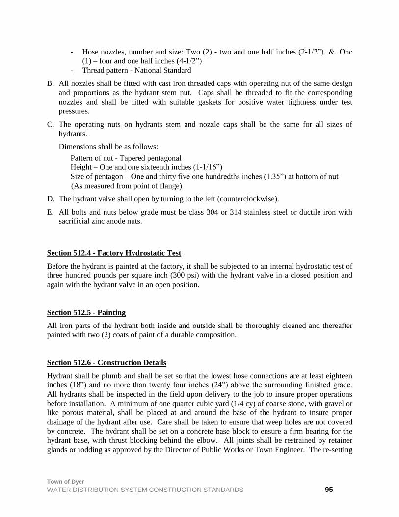
Town of Dyer
WATER DISTRIBUTION SYSTEM CONSTRUCTION STANDARDS 95
- Hose nozzles, number and size: Two (2) - two and one half inches (2-1/2”) & One
(1) – four and one half inches (4-1/2”)
- Thread pattern - National Standard
B. All nozzles shall be fitted with cast iron threaded caps with operating nut of the same design
and proportions as the hydrant stem nut. Caps shall be threaded to fit the corresponding
nozzles and shall be fitted with suitable gaskets for positive water tightness under test
pressures.
C. The operating nuts on hydrants stem and nozzle caps shall be the same for all sizes of
hydrants.
Dimensions shall be as follows:
Pattern of nut - Tapered pentagonal
Height – One and one sixteenth inches (1-1/16”)
Size of pentagon – One and thirty five one hundredths inches (1.35”) at bottom of nut
(As measured from point of flange)
D. The hydrant valve shall open by turning to the left (counterclockwise).
E. All bolts and nuts below grade must be class 304 or 314 stainless steel or ductile iron with
sacrificial zinc anode nuts.
Section 512.4 - Factory Hydrostatic Test
Before the hydrant is painted at the factory, it shall be subjected to an internal hydrostatic test of
three hundred pounds per square inch (300 psi) with the hydrant valve in a closed position and
again with the hydrant valve in an open position.
Section 512.5 - Painting
All iron parts of the hydrant both inside and outside shall be thoroughly cleaned and thereafter
painted with two (2) coats of paint of a durable composition.
Section 512.6 - Construction Details
Hydrant shall be plumb and shall be set so that the lowest hose connections are at least eighteen
inches (18”) and no more than twenty four inches (24”) above the surrounding finished grade.
All hydrants shall be inspected in the field upon delivery to the job to insure proper operations
before installation. A minimum of one quarter cubic yard (1/4 cy) of coarse stone, with gravel or
like porous material, shall be placed at and around the base of the hydrant to insure proper
drainage of the hydrant after use. Care shall be taken to ensure that weep holes are not covered
by concrete. The hydrant shall be set on a concrete base block to ensure a firm bearing for the
hydrant base, with thrust blocking behind the elbow. All joints shall be restrained by retainer
glands or rodding as approved by the Director of Public Works or Town Engineer. The re-setting

Town of Dyer
WATER DISTRIBUTION SYSTEM CONSTRUCTION STANDARDS 96
of existing hydrants and moving and reconnection of existing hydrants shall be handled in a
manner similar to a new installation.
Section 512.7 - Hydrant Location
Where public water supplies may be extended, fire hydrants shall be installed along public
streets.
Hydrants shall be installed in residential districts on the basis of serving one hundred twenty
thousand square feet (120,000 sf) of area and not be more than three hundred fifty feet (350’)
apart. Hydrants shall be located within the public right of way or easement, at the side property
lines.
The farthest distance from a hydrant to any point on a building it services shall be three hundred
fifty linear feet (350’). In commercial and industrial districts, hydrants shall be installed on the
basis of serving eighty thousand square feet (80,000 sf) of area and not be more than two hundred
fifty feet (250’) apart.
The closest edge of an installed hydrant shall be no closer than approximately forty-two inches
(42”) from the back of the street curb and no further than approximately forty-eight inches (48”)
distant.
Section 513.0 - Polyethylene Encasements
This covers materials specifications and installation procedures for polyethylene encasements to
the underground installations of gray and ductile cast iron pipe and other related appurtenances of
water main. Polyethylene encasements shall be required of all newly constructed water mains
and fittings, in accordance with AWWA-C105. The installation method shall be approved by the
Director of Public Works or Town Engineer.
Section 514.0 - Fire Flow Requirements
The amount of water necessary to fight a fire for a particular building is called the required fire
flow. It is based on the type of construction, building size, and fire hazard of the occupancy.
Fire flow calculations shall be prepared in accordance with the Guide for Determination of
Required Fire Flow, published by Insurance Services Office, Inc. (ISO).
The design engineer shall show that the water system can supply the required fire flow.
The minimum fire flow requirement shall be as noted below:
- Residential – 1,500 GPM
- Industrial/Commercial – 3,500 GPM

Town of Dyer
WATER DISTRIBUTION SYSTEM CONSTRUCTION STANDARDS 97
The Dyer Water Board and Fire Chief, jointly, shall review and approve plans and specifications
related to fire flows.
Section 514.1 - Minimum Size
The minimum permissible sizes for water main are, as follows:
A. Residential: 8" ø = 0.3491 ft2
B. Commercial: 10" ø = 0.5454 ft2
C. Industrial: 12" ø = 0.7854 ft2
Section 515.0 - Water Services
Section 515.1 - Installation
The minimum size of water service connections in the Town of Dyer shall be one inch (1") and
shall be copper tube type "K". Water service connections four-inches (4") and larger shall be
ductile iron pipe water main and shall comply with all specifications for water mains. All copper
connections shall be made with compression fittings.
The corporation stop shall be Mueller Company H-1500 Ori-seal III or approved equal and shall
be installed by tapping machine. The tap shall be made in the upper third of the main as close to
a forty-five degree (45°) angle with the horizontal axis as is practical. A tap into the top of the
main will not be permitted. All taps shall have a minimum of one foot (1’) separation.
The round way ground key stop shall be Mueller Company H-1504-2 Ori-seal III with quarter
turn check or approved equal. Buffalo box shall be Mueller Company H-10334 Arch Type with
thirty three inch (33”) rod or approved equal five and one half feet (5-1/2’) in length having an
inside diameter of the upper section of not less than one inch (1"). All water services shall have a
minimum of five feet (5’) of cover over the service. All buffalo boxes shall be installed
approximately eighteen inches (18”) from the street side of the sidewalk.
The contractor shall record the location of each buffalo box in relation to the nearest corner lot
line. Two copies of this record shall be filed with the Town prior to final inspection. When a
water service is installed beneath existing roadways, sidewalks and/or driveways, the pipe shall
be installed by pushing or auguring a hole beneath the said roadway, sidewalk and/or driveway
and installing the service pipe through the hole.
The size of any opening in the roadway to connect the water service to the main shall be kept to a
minimum, and the roadway replaced in accordance with Section 600, materials and thickness to
be approved by the Town.
Installation of a water service in the same trench as the sanitary sewer service will not be
allowed. A ten-foot (10’) horizontal separation between a sanitary sewer and water service shall
be maintained. The buffalo box shall not be placed within a hard surface sidewalk, driveway or
access drive.
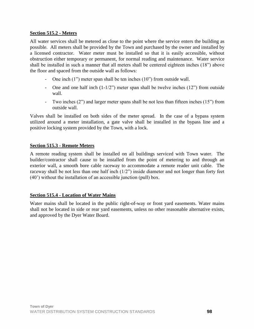
Town of Dyer
WATER DISTRIBUTION SYSTEM CONSTRUCTION STANDARDS 98
Section 515.2 - Meters
All water services shall be metered as close to the point where the service enters the building as
possible. All meters shall be provided by the Town and purchased by the owner and installed by
a licensed contractor. Water meter must be installed so that it is easily accessible, without
obstruction either temporary or permanent, for normal reading and maintenance. Water service
shall be installed in such a manner that all meters shall be centered eighteen inches (18”) above
the floor and spaced from the outside wall as follows:
- One inch (1”) meter span shall be ten inches (10”) from outside wall.
- One and one half inch (1-1/2”) meter span shall be twelve inches (12”) from outside
wall.
- Two inches (2”) and larger meter spans shall be not less than fifteen inches (15”) from
outside wall.
Valves shall be installed on both sides of the meter spread. In the case of a bypass system
utilized around a meter installation, a gate valve shall be installed in the bypass line and a
positive locking system provided by the Town, with a lock.
Section 515.3 - Remote Meters
A remote reading system shall be installed on all buildings serviced with Town water. The
builder/contractor shall cause to be installed from the point of metering to and through an
exterior wall, a smooth bore cable raceway to accommodate a remote reader unit cable. The
raceway shall be not less than one half inch (1/2”) inside diameter and not longer than forty feet
(40’) without the installation of an accessible junction (pull) box.
Section 515.4 - Location of Water Mains
Water mains shall be located in the public right-of-way or front yard easements. Water mains
shall not be located in side or rear yard easements, unless no other reasonable alternative exists,
and approved by the Dyer Water Board.

Town of Dyer
STREET PAVEMENTS, CURB AND GUTTER CONSTRUCTION STANDARDS 99
STREET PAVEMENTS, CURB AND GUTTER
CONSTRUCTION STANDARDS
Section 600.0 - General
The standards and requirements found in this article are for the materials and construction of
street improvements within the Town of Dyer. Both rigid and flexible pavement construction are
permitted in the Town. All proposed roadways shall have soil testing performed as directed by
the Director of Public Works or the Town Engineer prior to construction.
Section 600.1 – Erosion and Sediment Control
Erosion Control Plans shall be submitted as part of the Primary and Final Engineering Plans. See
Section 1100, Erosion and Sediment Control Standards for complete requirements.
Section 601.0 - Rigid (Concrete) Pavement
The pavement shall be of Portland Cement Concrete with reinforcement constructed on a
prepared subgrade. The design of Portland Cement Concrete pavement section shall be based
upon the existing soil conditions and projected traffic. Arbitrary section is not permissible.
Section 601.1 - Materials
The materials used to arrive at an acceptable concrete mixture such as Portland Cement, fine and
coarse aggregates, and water shall conform to the quality requirements as enumerated in
appropriate Articles of the Standard Specifications of Indiana Department of Transportation,
latest revision.
Section 601.2 - Quality of Mix
The concrete mix shall be uniform throughout and shall contain no less than five percent (5%)
nor more than seven percent (7%) entrained air by volume, and concrete in place in the form of
finished pavement shall have a minimum of six percent (6%) entrained air. The slump shall be
no more than four inches (4"). At least six (6) sacks of cement will be required for each cubic
yard of concrete.
Air-entraining agents shall have proven compatibility with all local concrete materials, including
cement, and shall be capable of providing in the concrete the required air contents and an air-void
system known to produce durable, scale-resistant concrete.
The comprehensive strength shall be determined in accordance with ASTM Designation: C31.
The minimum twenty-eight (28) day compressive strength shall be four thousand pounds per
square inch (4,000 psi).
No admixtures shall be used in the concrete without prior approval, and all approved admixtures
shall meet applicable AASHO and ASTM requirements.
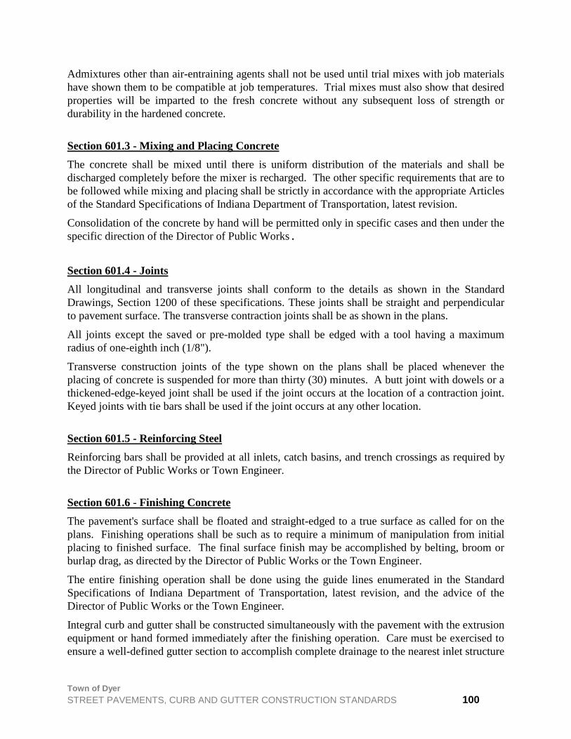
Town of Dyer
STREET PAVEMENTS, CURB AND GUTTER CONSTRUCTION STANDARDS 100
Admixtures other than air-entraining agents shall not be used until trial mixes with job materials
have shown them to be compatible at job temperatures. Trial mixes must also show that desired
properties will be imparted to the fresh concrete without any subsequent loss of strength or
durability in the hardened concrete.
Section 601.3 - Mixing and Placing Concrete
The concrete shall be mixed until there is uniform distribution of the materials and shall be
discharged completely before the mixer is recharged. The other specific requirements that are to
be followed while mixing and placing shall be strictly in accordance with the appropriate Articles
of the Standard Specifications of Indiana Department of Transportation, latest revision.
Consolidation of the concrete by hand will be permitted only in specific cases and then under the
specific direction of the Director of Public Works.
Section 601.4 - Joints
All longitudinal and transverse joints shall conform to the details as shown in the Standard
Drawings, Section 1200 of these specifications. These joints shall be straight and perpendicular
to pavement surface. The transverse contraction joints shall be as shown in the plans.
All joints except the saved or pre-molded type shall be edged with a tool having a maximum
radius of one-eighth inch (1/8").
Transverse construction joints of the type shown on the plans shall be placed whenever the
placing of concrete is suspended for more than thirty (30) minutes. A butt joint with dowels or a
thickened-edge-keyed joint shall be used if the joint occurs at the location of a contraction joint.
Keyed joints with tie bars shall be used if the joint occurs at any other location.
Section 601.5 - Reinforcing Steel
Reinforcing bars shall be provided at all inlets, catch basins, and trench crossings as required by
the Director of Public Works or Town Engineer.
Section 601.6 - Finishing Concrete
The pavement's surface shall be floated and straight-edged to a true surface as called for on the
plans. Finishing operations shall be such as to require a minimum of manipulation from initial
placing to finished surface. The final surface finish may be accomplished by belting, broom or
burlap drag, as directed by the Director of Public Works or the Town Engineer.
The entire finishing operation shall be done using the guide lines enumerated in the Standard
Specifications of Indiana Department of Transportation, latest revision, and the advice of the
Director of Public Works or the Town Engineer.
Integral curb and gutter shall be constructed simultaneously with the pavement with the extrusion
equipment or hand formed immediately after the finishing operation. Care must be exercised to
ensure a well-defined gutter section to accomplish complete drainage to the nearest inlet structure

Town of Dyer
STREET PAVEMENTS, CURB AND GUTTER CONSTRUCTION STANDARDS 101
in accordance with the plans. Incomplete gutter drainage shall be corrected at the contractor’s
expense, satisfactorily at the discretion of the Director of Public Works or Town Engineer.
Section 601.7 - Curing
The surface of the newly laid pavement shall be cured in a manner as called for in the Standard
Specifications of Indiana Department of Transportation, latest revision, and satisfactory to the
Director of Public Works.
Special attention is hereby called for the protection of fresh concrete against cold weather, which
should follow the measures discussed in the Standard Specifications of Indiana Department of
Transportation, latest revision.
Section 601.8 - Cold Weather Concreting
Except by specific written authorization by the Director of Public Works or Town Engineer,
concrete placing shall cease when the descending air temperature in the shade falls below forty
degrees Fahrenheit (40 F). When concrete placing is permitted during cold weather, the
temperature of the mixed concrete shall not be less than fifty degrees Fahrenheit (50 F) or more
than one hundred degrees Fahrenheit (100 F) at the time of placement in the forms. The
aggregates may be heated by steam, or dry heat prior to being placed in the mixer. The water
shall not be hotter than one hundred seventy degrees Fahrenheit (170 F). When concrete is
being placed during cold weather and the air temperature may be expected to drop below thirty-
five degrees Fahrenheit (35 F) a supply of straw or other suitable blanketing material shall be
provided along the line of the work. Care must be exercised to prevent the wind from removing
the heat protection.
At any time when the air temperature may be expected to reach the freezing of the concrete, such
heat protection shall be maintained for at least six (6) days. If required by the Director of Public
Works, concrete less than twenty-four (24) hours old shall also be covered by approved devices
capable of maintaining the temperature within the concrete at fifty degrees Fahrenheit (50 F) or
higher. Concrete injured by frost action shall be removed and replaced at the Contractor's
expense.
Other construction and precautionary measures for this special weather concreting shall follow
the requirements set forth in the applicable sections of the Standard Specifications of Indiana
Department of Transportation, latest revision.
Section 601.9 - Sealing Joints
After the curing period all sawed and dummy groove joints shall be cleaned and sealed with
either hot or cold-applied material, meeting the approval of the Director of Public Works. The
joints shall be surface dried and thoroughly cleaned of sealing the joints and the quality of
material should follow the procedures discussed in the Standard Specifications of Indiana
Department of Transportation, latest revision.
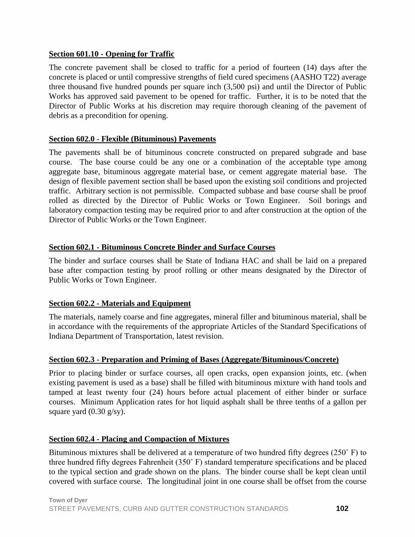
Town of Dyer
STREET PAVEMENTS, CURB AND GUTTER CONSTRUCTION STANDARDS 102
Section 601.10 - Opening for Traffic
The concrete pavement shall be closed to traffic for a period of fourteen (14) days after the
concrete is placed or until compressive strengths of field cured specimens (AASHO T22) average
three thousand five hundred pounds per square inch (3,500 psi) and until the Director of Public
Works has approved said pavement to be opened for traffic. Further, it is to be noted that the
Director of Public Works at his discretion may require thorough cleaning of the pavement of
debris as a precondition for opening.
Section 602.0 - Flexible (Bituminous) Pavements
The pavements shall be of bituminous concrete constructed on prepared subgrade and base
course. The base course could be any one or a combination of the acceptable type among
aggregate base, bituminous aggregate material base, or cement aggregate material base. The
design of flexible pavement section shall be based upon the existing soil conditions and projected
traffic. Arbitrary section is not permissible. Compacted subbase and base course shall be proof
rolled as directed by the Director of Public Works or Town Engineer. Soil borings and
laboratory compaction testing may be required prior to and after construction at the option of the
Director of Public Works or the Town Engineer.
Section 602.1 - Bituminous Concrete Binder and Surface Courses
The binder and surface courses shall be State of Indiana HAC and shall be laid on a prepared
base after compaction testing by proof rolling or other means designated by the Director of
Public Works or Town Engineer.
Section 602.2 - Materials and Equipment
The materials, namely coarse and fine aggregates, mineral filler and bituminous material, shall be
in accordance with the requirements of the appropriate Articles of the Standard Specifications of
Indiana Department of Transportation, latest revision.
Section 602.3 - Preparation and Priming of Bases (Aggregate/Bituminous/Concrete)
Prior to placing binder or surface courses, all open cracks, open expansion joints, etc. (when
existing pavement is used as a base) shall be filled with bituminous mixture with hand tools and
tamped at least twenty four (24) hours before actual placement of either binder or surface
courses. Minimum Application rates for hot liquid asphalt shall be three tenths of a gallon per
square yard (0.30 g/sy).
Section 602.4 - Placing and Compaction of Mixtures
Bituminous mixtures shall be delivered at a temperature of two hundred fifty degrees (250˚ F) to
three hundred fifty degrees Fahrenheit (350˚ F) standard temperature specifications and be placed
to the typical section and grade shown on the plans. The binder course shall be kept clean until
covered with surface course. The longitudinal joint in one course shall be offset from the course

Town of Dyer
STREET PAVEMENTS, CURB AND GUTTER CONSTRUCTION STANDARDS 103
below by not less than three inches (3”) and in the surface course it shall be at the centerline of
the pavement. The spreading and finishing machine shall be operated at a speed that will insure
a continuous operation not to exceed thirty five feet per minute (35 fpm).
After the mixture is placed, it shall be given an initial or breakdown rolling with either three-
wheel roller or pneumatic tired roller, or tandem roller or vibratory roller. The compaction
achievement shall be of the order of not less than ninety three percent (93%) of the maximum
possible density of void less mixture composed of the same materials in like proportions.
The speed of the roller at all times shall be slow enough to avoid displacement of the bituminous
mixture. If displacement occurs, it shall be corrected at once by raking and applying fresh
bituminous mixture where required. Rolling shall be continued until all roller marks are
eliminated and the bituminous mixture is satisfactorily compacted.
Any bituminous mixture that becomes loose, broken, mixed with foreign materials, or is in any
way defective shall be removed and replaced with fresh hot mixture and compacted to conform
to the surrounding area.
The density of the finished courses shall be obtained from specimens furnished by the
Contractor, by core drilling the compacted courses. The number of cores and the locations for
removing shall be approved by the Town Engineer or Director of Public Works.
Section 602.5 - Joints
Joints between old and new pavements or between successive days work shall be made to insure
thorough and continuous bond between the old and new mixtures.
Contact surfaces of curbs, gutters, manholes and similar structures shall be painted with a thin
uniform coating of liquid asphalt, or appropriate tar before the bituminous mixture is placed
against them. The mixture shall be placed uniformly high so that after compaction it will be one
quarter inch (1/4”) above the edges of such structures.
Section 602.6 - Protection of Pavement
The contractor shall protect all sections of newly compacted and surface courses from traffic
until they have hardened to the satisfaction of the Director of Public Works. Minimum curing
time shall be twenty four (24) hours.
Section 602.7 - Aggregate Base Course
The base course shall be Indiana #53 (Limestone only). The use of slag material is not an
acceptable alternative. The quality and gradation of materials, method of compaction and
construction shall follow the requirements set forth in the Standard Specifications of Indiana
Department of Transportation, latest revision. Thickness shall be as detailed in the Standard
Drawings in Section 1200.
A minimum of three inches (3") of aggregate base course shall be required under all curbs and
gutters.
Town of Dyer
STREET PAVEMENTS, CURB AND GUTTER CONSTRUCTION STANDARDS 104
Section 602.8 - Bituminous Base Course
The quality of aggregate bituminous material, method of mixing, quality of mix, construction
compaction, and testing shall be fully in conformance with the requirements set forth in the
Standard Specifications of Indiana Department of Transportation, latest revision. Compacted
thickness shall be as detailed in the Standard Drawings in Section 1200.
Section 602.9 - Cement Aggregate Mixture
Cement aggregate mixture may be used as a base course at the consent of the Director of Public
Works. The quality of the mix, method of construction finishing, curing, etc. shall follow the
requirements in the Standard Specifications of Indiana Department of Transportation, latest
revision.
Section 602.10 - Hot Asphalt Binder Course
Hot asphalt binder course shall be a minimum of two inches (2") thick. Hot asphalt emulsion
(HAE) or hot asphalt concrete (HAC) binder 8 or 9, MV mixed and placed in accordance with
appropriate requirements of the Standard Specifications of Indiana Department of Transportation,
latest revision.
Section 602.11 - Hot Asphalt Surface Course
Hot asphalt surface course shall be a minimum of one and one half inch (1-1/2") thick. Hot
asphalt emulsion (HAE) or hot asphalt concrete (HAC) surface 11 MV mixed and placed in
accordance with the appropriate requirements of the Standard Specifications of Indiana
Department of Transportation, latest revision. No surface course can be applied until eighty
percent (80%) of housing construction per unit and/or development is complete or on streets that
are designated as construction thoroughfare for future developments.
Section 602.12 - Tack Coat
Tack coat shall be in accordance with the appropriate requirements of the Standard Specifications
of Indiana Department of Transportation, latest revision.
Section 602.13 - Subgrade
The subgrade preparation and its shaping to receive the base course of the pavement shall be
done to the complete satisfaction of the Director of Public Works or Town Engineer and in
accordance with the requirements noted in the Standard Specifications of Indiana Department of
Transportation, latest revision.
Section 602.14 - Geotextile Pavement Fabric
The use of a geotextile pavement fabric is required and shall be in accordance with the
appropriate requirements of the Standard Specifications of Indiana Department of Transportation,
latest revision.
Town of Dyer
STREET PAVEMENTS, CURB AND GUTTER CONSTRUCTION STANDARDS 105
Section 603.0 - Concrete Curb, Gutter, Median
The concrete curb, gutter and median shall be built to the line, grade and sections shown on the
plans. The controlling principles for mix, consistency, air content, and strength shall be the same
as that for concrete pavement, as noted in the Standard Specifications, and shall be of the type
shown on the Standard Drawings in Section 1200.

Town of Dyer
SIDEWALKS 106
SIDEWALK STANDARDS
Section 700.0 - General
The Standards and Specifications enumerated in this article for materials and construction pertain
to sidewalk construction within the Town of Dyer, which shall comply with Section 604 of the
“Standard Specifications of the Indiana Department of Transportation,” latest revision, including
all referred Sections except as modified herein.
Handicap accessibility ramps and curb cuts shall be required as noted in the Standard Drawings
in Section 1200 and as required by the State of Indiana.
Section 701.0 - Concrete Sidewalk
The sidewalk shall be of Portland Cement Concrete constructed on a prepared subgrade with
various joints as shown in the Standard and subscribed herein.
Section 701.1 – Location
The public sidewalk shall be located at the edge of the right-of-way, except as otherwise
indicated on the approved plans.
Section 701.2 - Earth Excavation
The excavation shall consist of removing all topsoil to a width of one foot (1') on either side of
the sidewalk, cutting or filling to within six inches (6") of the top of the sidewalk and compacting
all fill to a minimum of ninety percent (90%) Standard Proctor Density, AASHO, Designation: T9
Section 701.3 - Subgrade Preparation
The subgrade shall consist of four inches (4") of sand, stone or granular material which shall be
tamped or rolled until thoroughly compacted and shall be constructed true to grade and cross
section. Until the subgrade and forms are approved by the Director of Public Works or Town
Engineer, no concrete shall be poured.
Excavation shall be made to a depth of six or eight inches (6" or 8") below finished grade, width
not less than six inches (6") wider on each side than the width of the sidewalk. Tree roots
exposed by excavation should be cut off at least three inches (3") outside of the new walk and
three inches (3") below subgrade. Subgrade shall be tamped or rolled until thoroughly
compacted and shall be true to grade and cross section for the bottom of sidewalk.
Section 701.4 - Materials
The materials used to arrive at an acceptable concrete mixture such as Portland Cement, fine and
coarse aggregates, and water shall conform to the quality requirements as enumerated in

Town of Dyer
SIDEWALKS 107
appropriate Articles of the Standard Specifications of Indiana Department of Transportation,
latest revision.
Section 701.5 - Forms
Side forms shall be of lumber of not less than two inches (2") nominal thickness or of steel of
equal rigidity. They shall be four inches (4") in depth. They shall be held securely in place by
stakes or braces, with top edges true to line and grade. The forms for the sidewalks shall be so
set that the slab will have a fall of one-quarter inch vertical to one foot horizontal (1/4”:1’) from
the edge farthest from the street toward the edge nearest the street. Forms for the sidewalk
aprons shall be so set that the slab will have a uniform fall between the sidewalk proper and the
curb grade. Forms shall be oiled before concrete is placed.
Section 701.6 - Removal of Forms
Forms shall remain undisturbed for a minimum of twelve (12) hours and until the concrete has
attained sufficient strength to sustain its own weight in addition to any temporary and permanent
loads that may be placed upon it.
Section 701.7 - Quality of Mix
Concrete for sidewalks and sidewalk aprons shall be composed of Portland Cement, clean coarse
aggregate, clean sharp sand for fine aggregate, and only clean potable water shall be used in
mixing the concrete. The Portland Cement Concrete shall have an air-entertainment of five to
seven percent (5%-7%) of the volume, and the mix shall be six (6) sack mix.
The concrete mix shall have a compressive strength of not less than three thousand five hundred
pounds per square inch (3500 psi) after twenty eight (28) days curing. The slump shall not be
greater than three inches (3").
Air-entertaining agents shall have proven compatibility with all local concrete materials,
including cement, and shall be capable of providing in the concrete the required air contents and
an air-void system known to produce durable, scale-resistant concrete.
Admixtures other than air-entertaining agents shall not be used until trial mixes with job
materials have shown them to be compatible at job temperatures. Trial mixes must also show
that desired properties will be imparted to the fresh concrete without any subsequent loss of
strength or durability in the hardened concrete.
Section 701.8 - Mixing
Concrete shall be mixed in a batch mixer for not less than one and one-half (1-1/2) minutes after
all the materials are in the miser drum and until there is a uniform distribution of the materials
and the concrete is uniform in color and is homogeneous. Small amounts of concrete may be
mixed by hand, subject to approval by the Director of Public Works.
Town of Dyer
SIDEWALKS 108
Section 701.9 - Placing and Finishing
Subgrade and forms shall be moistened just before concrete is placed. Concrete shall be placed
in successive batches for the entire width of slope, struck off from one half inch (1/2”) to three
quarter inch (3/4”) higher than the finished slope, tamped until all voids are removed and free
mortar appears on the surface, thoroughly spaded along the edges, struck off to the true grade,
and finished to a true and even surface with floats and trowels. Final troweling shall be done
with a steel trowel, leaving a smooth, even surface, but excessive working avoided. After the
water sheen has disappeared, the surface shall be given a final broom finish. The broom shall be
drawn across the sidewalk at right angles to edges of the walk, with adjacent strokes slightly
overlapping, producing a uniform, slightly roughened surface with parallel broom marks. In NO
case shall dry cement and/or sand be applied to dry-up the surface.
The surface shall be divided by grooves constructed at right angles to the centerline of the
sidewalk. These grooves shall extend to one-fourth (1/4) the depth of the sidewalk, with the
width being neither more than one-fourth (1/4) nor less than one-eighth (1/8). The grooves shall
be edged with the edging tool having a quarter inch (1/4”) radius. The walk shall be grooved at
five foot (5') intervals. The sidewalk at its junction with the curb shall usually be one quarter
inch (1/4”) above the curb.
Concrete when placed in the forms shall have a temperature of not less than seventy degrees
Fahrenheit (70° F), or more than one hundred degrees Fahrenheit (100° F). It is desirable that
freshly placed concrete shall be maintained at a temperature between fifty degrees and eighty
degrees Fahrenheit (50˚-80° F) for a period of not less than four (4) days after placement.
Section 701.10 - Sidewalk Width and Thickness
All sidewalks shall be a minimum of five feet (5’) wide. The concrete shall be placed with one
course, minimum thickness of five inches (5") and constructed on the prepared sub-grade.
Where vehicle crossing is permitted on the sidewalk, the thickness shall be a minimum of seven
inches (7") thick and reinforced with 6” x 6”, 10-gauge welded wire reinforcing, in accordance
with the appropriate requirements of the Standard Specifications of Indiana Department of
Transportation, latest revision.
Section 701.11 - Expansion Joints
Expansion joints of the thickness specified below shall consist of performed joint filler. The top
of the joint shall be placed one quarter inch (1/4") below the surface of the sidewalk.
(1) One-half inch (1/2") Thick Expansion Joints: Expansion joints 1/2” thick shall be placed
between the sidewalk and all structures such as light standards, traffic light standards, and
traffic poles, which extend through the sidewalk.
(2) Three-quarter inch (3/4") Thick Expansion Joints: Expansion joints 3/4" thick shall be
placed at intervals of forty-five feet (45') in the sidewalk or wherever it is practical.

Town of Dyer
STREET LIGHTING STANDARDS 109
STREET LIGHTING STANDARDS
Section 800.0 - Requirements for Underground Wiring
The developer shall make arrangements for all lines for telephone, electric, television, and other
similar services distributed by wire or cable to be placed underground entirely throughout a
subdivided area, except for major street rights-of-way.
Such conduits or cables shall be placed within dedicated public ways or easements where
applicable, provided only that overhead lines may be permitted by the plan commission where it
is determined that overhead lines will not constitute a detriment to the health, safety, general
welfare, plat design, and character of the subdivision.
All such facilities placed in dedicated public easements or rights-of-way shall be planned so as
not to conflict with other underground utilities. All such facilities shall be constructed in
accordance with standards of construction approved by the Indiana Commerce Commission, and
in conformance with said utilities franchise; all drainage and underground utility installations
which traverse privately owned property shall be protected by easements granted by the
developer.
Section 800.1 - Street Lighting
Street lighting improvements shall be installed to serve all properties within a subdivision or
planned unit development. Such improvements shall consist of standards, luminaries, cable,
conduit, controllers, and all other miscellaneous work and equipment necessary for the integrated
system of streetlights.
Section 801.0 – Design
Section 801.1 - Location
There shall be at least one luminary at each street intersection, curb, and cul-de-sac, or as directed
by the Director of Public Works or Town Engineer. The additional locations required to provide
sufficient illumination shall be in accordance with the latest edition of the American National
Standard practice for roadway lighting as published by the Illuminating Engineering Society of
North America.
Section 801.2 - Service
Power furnished by Northern Indiana Public Service Company shall be 120/240 volts, single
phase, three wire, at the utility’s transformer. The electrical service connection and location shall
be approved by the power company. A lockable, rain-tight disconnect box with appropriate size
circuit breakers shall be provided. Service shall be underground conduit from point of
connection to the proposed control station.

Town of Dyer
STREET LIGHTING STANDARDS 110
Section 801.3 - Control
An independent control cabinet will be installed at a location approved by Northern Indiana
Public Service and the Town of Dyer. Unless otherwise approved by the Town, the Controller
shall contain a main breaker for control circuit and a contactor. A photoelectric cell located at
the top of the pole shall control the contactor.
Section 801.4 - Voltage
All lighting circuits shall be 240 VAC. Control circuits shall be 120 VAC. Voltage drop shall
not exceed five percent (5%) from disconnect to last standard.
Section 801.5 - Light Standard
Light standards shall be aluminum pole and bracket arm with a nominal mounting height of thirty
feet (30’). Bracket arms shall be eight feet (8’), except at intersections which shall have twelve
feet (12’) bracket arms.
Section 801.6 - Light Distribution
All luminaries, except at intersections and cul-de-sacs, shall have MS type II distribution.
Intersections and cul-de-sacs shall have MS type II 4-way distribution. Shields shall be provided
where required to eliminate any unnecessary glare.
Section 801.7 - Underground Wiring
All wiring between poles shall be underground. Underground cable shall be of two (2) No. 6
AWG, one (1) conductor in one inch (1") duct, buried a minimum of thirty inches (30") below
finished grade. The cable shall be located two feet (2’) behind back of curb. Splicing of
underground cable will not be permitted.
Section 801.8 - Grounding
Grounding shall consist of Bard No. 6 AWG buried four inches (4") above the cable duct in the
trench.
A one-half inch by eight foot (1/2" x 8') copper-weld ground rod shall be located in the trench
outside each foundation and shall be connected to the ground wire and the grounding lug located
in the base of each lighting standard.
Section 801.9 - Pole Wiring
Pole wiring shall be No. 10 AWG type use wire in a continuous length from underground
distribution system to luminary. It shall be connected to the underground cable by means of a

Town of Dyer
STREET LIGHTING STANDARDS 111
waterproof in-the-line fuse holder. Cables shall be long enough to allow extensions through pole
hand hole of not less than six inches (6").
Section 801.10 - Luminaries
A subdivision shall be lighted by high-pressure sodium luminaries and shall be used throughout
the subdivision. All luminaries on secondary and minor streets, intersection and cul-de-sacs shall
be 150-watt high-pressure sodium.
Section 801.11 - Conduit
At all locations where the underground cable crosses a commercial driveway or roadway, two
inch (2") galvanized steel conduit shall be installed. The conduit shall extend one foot (1')
beyond the back of curb or edge of driveway, in all directions. The ends of all conduits shall be
provided with a pipe thread insulated conduit bushing.
Section 801.12 - Spacing
A maximum space between luminaries shall not exceed three hundred feet (300') and will always
be located within the public right-of-way or easement at the side property lines. Spacing shall
conform to the latest revision of the American National Standard Practice for Roadway Lighting
(ANSPRL) as published by the Illuminating Engineering Society of North America.
Section 801.13 - Foundations
Concrete foundations for light standards shall be a minimum of twenty-four inches (24") in
diameter and five feet (5') in length or depth. Anchor bolts shall be in one inch (1") in diameter,
thirty-six inches (36") in length, with four-inch (4") hook at the bottom. Each foundation shall
be provided with a sufficient number on non-metallic raceways for cable entry.
Section 801.14 - Materials
All materials shall be as specified below, or as approved by the Director of Public Works or
Town Engineer.
Section 802.0 - Aluminum Poles and Bracket Arm
Section 802.1 - Shaft
The shaft shall be a one-piece, round tapered tube of alloy 6063, and shall be full-length heat-
treated after welding on the base flange to produce T6 temper. Poles shall include a 4" x 6"

Town of Dyer
STREET LIGHTING STANDARDS 112
reinforced handhole centered eighteen inches (18") above the bottom of the shaft. A cover with
stainless steel screws shall be provided for the handhole.
Section 802.2 - Base flange
The base flange for the attachment of the shaft to the foundation shall be a one-piece cast socket
of aluminum alloy 356.
The flange shall be joined to the shaft by means of complete circumferential welds, externally at
the top of the flange and internally at the bottom of the shaft tube. Four anchor bolt covers of
aluminum alloy 43 and stainless steel screws for their attachment shall be provided.
Section 802.3 - Bracket Arm
The bracket arm shall be the truss type of design with an upper and lower member joined near the
luminary end of the arm and braced with a vertical strut. The upper member shall be the
continuous or wiring member and shall be a tapered tube ovalized at the pole shaft end with the
major dimension of the oval in a horizontal plane. Its nominal wall thickness shall be 1/8". The
lower member shall be standard pipe. Both the upper and lower members shall be attached to the
pole shaft with 1/4" thick wrought plates. The upper attachment shall be made with two 3/8"
stainless steel bolts and blind nuts, which have been installed in the pole shaft in the factory.
Wiring at the upper attachment shall be through a grommeted 1-1/4" diameter hole. The material
of the main bracket members and their attachment plates shall be alloy 6063-T6.
Section 802.4 - Shaft Cap
An ornamental cap of aluminum alloy shall be provided with each shaft. The cap shall be
fastened to the shaft by means of a stainless steel screw. Underwriter’s tags and labels shall be
permanently removed from the reels by the Engineer for the municipality's records. None shall
be refunded.
Conductors shall be No. 6 AWG and comply with Underwriters’ Standard No. 83 for
thermoplastic insulated conductors. Conductor insulation shall be heat and moisture resistant for
use in seventy five degree (75˚ F) temperatures, in dry and wet locations at 600 volts.
Conductors shall be stranded copper and comply with ASTM specification B-8, Class B.
Duct shall be of black polyethylene, flexible enough for easy coiling and uncoiling but rigid
enough to maintain its shape over its entire life when applied as shown.
It shall be permanently marked at twelve-inch (12") intervals on the outside with the
manufacturer's name or trademark. One-inch (1") duct shall have a wall thickness of .080 inches
minimum. The duct shall exceed the following requirements tested according to the
specifications indicated. The duct shall be flexible enough for easy coiling and uncoiling at ten
degrees Celsius (10˚ C).
Town of Dyer
STREET LIGHTING STANDARDS 113
Tensile Strength 3,100 PSI Min. ASTM D 638
Elongation 300% Min. ASTM D 638
Melt Index 0.3 Mx. ASTM D 1238
Carbon Black Content Less than 2.5% ASTM D 1603
Density of Base Resin 0.941 – 0.955 ASTM D 1505
Brittle Temperature 70˚ C. or Below ASTM D 746
80% Non-Failure
Environmental Stress
Crack Resistance Max.
Failures per 10 Specimens
After 48 Hours ASTM D 1693
Incremental Internal 75% of Values Listed
Pressure For Series 1 ASTM D 1598
Impact Resistance .9’ #In of Notch ASTM D 256
Method A
Unit duct shall be installed so that it is possible to withdraw a conductor and pull in a new one.
Under no circumstances shall bends be less than eighteen inches (18") radius.
Where unit duct terminates in an anchor base pole, the duct shall terminate at a point halfway
between the bottom of the pole and the handhole. The cables and conductors shall extend
eighteen inches (18") beyond the duct. It is intended that the duct can be pulled to the opening in
the handhole for pulling in a replacement conductor or cable. Ground conductor shall be No. 6
AWG bare soft-drawn copper, having been manufactured with twelve months of installation.
Section 802.5 - Miscellaneous Hardware
All nuts, bolts, and washers used in the fabrication of the pole shall be grade 18-8 stainless steel,
aluminum alloy 2024-T4 with alumilite No. 204 finish, or aluminum alloy 6061-T6, except for
anchorage hardware.
Section 802.6 - Grounding
Each pole shaft shall contain an internal lug with a 3/8" diameter hole for the purpose of
attaching a grounding connector.
Section 802.7 - Welding
Welding shall be done by the inert gas shielded metal arc method with consumable electrode.
Aluminum alloy 4043 electrode shall be used.

Town of Dyer
STREET LIGHTING STANDARDS 114
Section 802.8 - Surface Finish
The pole shaft shall be provided with a satin finish accomplished by mechanical rotary grinding.
The bracket arms shall be provided with a satin-etched finish. All materials shall be cleaned and
free from dents and unsightly scratches.
Section 802.9 - Luminary
The luminary housing, both upper and lower, shall consist of cast aluminum joined by an
integrally cast pin hinge at the mounting, and a one-hand latch at the door. The reflector shall be
highly polished anodic-surfaced aluminum secured with spring latch for easy positioning. The
refractor shall be of the unbreakable type secured with spring latches. The ballast shall be the
regulator type, wired for 240-volt operation. It shall be suitable for high ambient temperature
operation, and by the Model G.E. M-400 type, or and approved equal.
The luminary shall have a adjustable socket capable of producing an MS II or MS II 4-way
distribution. Also, it shall be capable of adapting to one and one quarter inches (1-1/4") or two
inches (2") mounting brackets.
Section 802.10 - Lamp
150-Watt High-Pressure Sodium Vapor Lamps:
The lamp shall be designed to burn in any position and have a rated life of 24,000 hours with 10
hours burning time per start and shall come to full candle power in not over four minutes after
starting. The lamp shall have a minimum initial lumen output of 27,500 and 16,000 lumens
respectively, and shall provide ninety eight percent (98%) of the initial lumens after 6,000 hours
of operation. The maximum operating temperature shall not exceed one hundred twenty degrees
Celsius (120˚ C) at the inside bottom of the reflector when operating at twenty five degrees (25˚)
ambient temperature.
Section 802.11 - Cable-In-Duct
The cable duct assembly shall be made at the factory in continuous lengths that will permit
installation of the longest spans shown on the plans without splicing or cutting either conduit or
cable. Splices of cable or conduit will be permitted only in handholes or pole bases. None will
be permitted in the trench. Both conduit and cable will be continuous from pole to pole. The
unit duct assembly shall be factory coiled and delivered on reels with identifying underwriters'
tags and labels attached there to.
Section 802.12 - Conduit
Conduit shall be hot-dipped galvanized rigid steel with galvanized threads, conforming to
applicable sections of ANSI C80.1 and C80.4 and ASTM A 53.

Town of Dyer
STREET LIGHTING STANDARDS 115
Section 802.13 - Foundation
The concrete pole foundation shall conform to the specifications of Class X concrete as
contained in the appropriate Articles of the Standard Specifications of Indiana Department of
Transportation, latest revision.
Section 802.14 - Fuse Holder
The fuse holder shall be made of a durable molded plastic material in two sections held together
with a captive nut. Waterproofing shall be provided by an "O" ring at the point of connection.
The fuse will be held on the load side of the unit when separated, the line being recessed. The
tubular terminals on each end of the fuse holder shall be the crimp-type and shall accommodate
various sized of wire on the line side. A crimpable insulating sleeve covers each terminal to
provide a good surface for taping. The fuse holder to be used shall be HEB-AB and HEB-AD,
and each fuse holder shall come complete with a 13/32" X 1-1/2" fuse, type KTK, rated at 10
amps complete with boot style covers.
Section 803.0 - Inspections and Approvals
All street lighting plans shall be approved by the Director of Public Works or Town Engineer
prior to construction.
After the electric cable is in place, and before being connected to the luminaries and equipment,
the system shall be tested for shorts and grounds by means of an approved type of constant
potential 'Megger' in the presence of the Director of Public Works or Town Engineer. All cables
showing insulations resistance lower than recommended by the cable manufacturer shall be
replaced.
Luminaries shall be adjusted to the satisfaction of the Director of Public Works or Town
Engineer to obtain proper distribution. After notification that the work is complete, the Town
will make such tests and inspections as it may deem necessary to determine the acceptability of
the system. The developer shall furnish all labor and equipment necessary for the above tests at
no cost to the Town.
As-built plans will be submitted to the Town at or prior to the final inspection of the installation
or the final inspection shall not be considered complete.
Section 804.0 - Street Signs
All street signs and information signs and miscellaneous hardware must be installed before final
approval is given.

Town of Dyer
STORM WATER DETENTION 116
STORM WATER DETENTION STANDARDS
Section 900.0 - General
The following shall govern the design of any improvement with respect to the detention of storm
water runoff.
All storm water runoff of a proposed development shall be collected and flow into the proposed
storm sewer system and storm water detention facility (as required) to minimize direct discharge
into the Town of Dyer’s streams, ditches and ponds as well as private water courses.
Section 901.0 - Acceptable Detention Methods
All proposed developments shall provide storm water detention and/or retention system in
accordance with the herein contained specifications.
Existing residential or commercial developments that are expanding their facilities shall provide
additional storm water detention. The existing development may be required to provide
detention for the entire existing site as required by the Dyer Storm Water Management Board,
with input and recommendations from the Director of Public Works and Town Engineer.
The increased storm water runoff resulting from a proposed development should be detained on-
site by the provisions of appropriate wet or dry bottom reservoirs. Storage on or over parking
lots is not allowed. Measures which retard the rate of overland flow and the velocity in runoff
channels shall also be used to control the runoff rate partially. Detention basins shall be sized to
store excess flows from storms with a one hundred year (100 yr) storm event return period.
Control devices shall limit the discharge to a rate no greater than that prescribed by this
Ordinance (see Section 902.1 Allowable Release Rate).
Section 902.0 - Design Storm
Design of storm water detention facilities shall be based on a 100-yr storm event return period,
using the critical duration which produces the peak runoff. The storage volume and outflow rate
shall be sufficient to handle storm water runoff from a critical duration storm, as defined herein.
Rainfall depth-duration-frequency relationships and intensity-duration-frequency relationships of
Frequency Atlas of the Midwest – Bulletin 71 shall be used. (See following page)

Town of Dyer
STORM WATER DETENTION 117
Section 902.1 - Allowable Release Rate
The allowable release rate of storm water originating from a proposed development shall not
exceed fifteen hundredths cubic feet per second (0.15 cfs) per acre or the two year (2-yr) storm
event return period pre-development release rate.
In the event the natural downstream channel or storm sewer system is inadequate to
accommodate the release rate provided above, than the allowable release rate shall be reduced to
that rate permitted by the capacity of the receiving downstream channel or storm sewer system.
Additional detention, as determined by the Board of Storm Water Management after review and
recommendation by the Plan Commission, shall be required to store that portion of the runoff
exceeding the capacity of the receiving sewers or waterways.
The Natural Resources Conservation Service (NRCS) TR-55 computer model with the NRCS
TR-55 time-of-concentration and curve number calculation methodologies, and the Huff Third
Quartile (50%) rainfall distributions must be used to determine the 2-yr return period, pre-
development release for areas greater than five acres (5 Ac) and for sites with exiting depression
storage.
The Rational Method may be used to determine the 2-yr return period pre-development release
rate for sites of less than 5 Ac of commonly contiguous property where no depression storage
exists.
If more than one (1) detention basin is involved in the development of the area upstream of the
limiting restriction, the allowable release rate from any one detention basin shall be in direct
proportion to the ratio of its drainage area to the drainage area of the entire watershed upstream
of the restriction.

Town of Dyer
STORM WATER DETENTION 118
Section 902.2 - Drainage System Overflow Design
All detention/retention facilities shall be provided with a high-water, overflow, emergency
facility at the location of the basin itself as well as an overland flow route for the proposed
development, calculated to contain the flow from the 100-yr storm event to the downstream
receiving stream.
Drainage systems shall have adequate capacity to convey the storm water runoff from all
upstream tributary areas through the development under consideration for a 100-yr storm event
return period calculated on the basis of the upstream land in its present state of development. An
allowance equivalent to the reduction in flow rate provided shall be made for upstream detention
when such upstream detention and release rate have previously been approved by the Board of
Storm Water Management after review of recommendation of the Plan Commission and
evidence of its construction can be shown. See Dyer Town Code Section 9, Article 915.0.
Section 902.3 - Determination of Storage Volume: Rational Method
For areas of five acres (5 Ac) or less, the Rational Method may be used to determine the required
volume of storm water storage, for a 100-yr storm event return period. The following thirteen
step procedure may be used to determine the required volume of storage.
Other design methods may also be used, subject to the approval of the Town Engineer in
conformance with generally accepted Engineering standards and practices.
Due to changes and different hydrology requirements, the Storm Water Management Board or
Town Engineer may require additional storm water storage beyond the amounts herein contained.
Steps Procedures
1. Determine Total Drainage Area in acres “A”;
2. Determine Undeveloped Composite Runoff Coefficient “Cu” based on existing land use;
3. Determine Time of Concentration “Tc” in minutes based on existing conditions
(Maximum Time of Concentration, Tc = 30 minutes);
4. Determine 2-yr storm event Rainfall Intensity “Iu” in inches per hour, based on time of
concentration;
5. Compute Undeveloped Runoff “Qu” based on existing land use, and 2–yr return period,
Qu = Cu*Iu*A. Use the 2-yr undeveloped runoff or 0.15 cfs per acre, whichever is less;
6. Determine Developed Composite Runoff Coefficient “Cd” based on proposed conditions
and a 100-yr storm event return period;
7. Determine the 100-yr storm event Rainfall Intensity “Id” for various storm durations
“Td” up through the time of concentration for the developed area;
8. Determine Developed Inflow Rates “Qd” for various storm durations Td, measured in
hours; Qd = Cd*Id*A;

Town of Dyer
STORM WATER DETENTION 119
9. Compute a Storage Rate of “Std” for various storm durations Td up through the time of
concentration of the developed area; Std = Qd – Qu
10. Compute Required Storage Volume “SR” in acre-feet for each storm duration Td; this
assumes a triangular hydrograph of duration (2*Td) hours with the peak flow of Std at Td
hours; SR = (Std) (Td/12)
11. Select the largest storage volume computed in Step 10 for any storm duration Td for
detention basin design;
12. Calculate Outflow Restrictor Size, minimum restriction size = 3.0”.
Example:
13. Assumed Example Data: Tributary Area = 5 acres, Cu = 0.20, Cd = 0.75, Tu = 75 min,
Rainfall Intensity (for Tc=75 min, 2-yr storm event) Iu = 1.23 in/hr
Qu1 = 0.2 * 1.23 * 5 = 1.23 cfs ; Qu2 = 0.15 * 5 = 0.75 cfs ; Use Qu = 0.75 cfs
Example Detention Calculations: Rational Method
A B C D E F G H
DEVELOPED STORM RAINFALL RAINFALL PROPOSED DEVELOPED UNDEVELOPED STORAGE REQUIRED COMPOSITE
RUNOFF COEFFICIENT
DURATION TIME
FREQUENCY INTENSITY DEVELOPMENT INFLOW RATE
RUNOFF RATE RATE STORAGE VOLUME SR
100-YR 100-YR DRAINAGE AREA
Qd Qu=0.15*A Std Col G * Col B (Hrs) / 12
Cd (MIN) (HR) (IN) (IN/HR) (Acres) (CFS) (CFS) (CFS) (ACRE*FEET)
0.75 5 0.08 0.85 10.20 5.00 38.25 0.75 37.50 0.26
0.75 10 0.17 1.50 9.00 5.00 33.75 0.75 33.00 0.46
0.75 15 0.25 1.92 7.68 5.00 28.80 0.75 28.05 0.58
0.75 30 0.50 2.63 5.26 5.00 19.73 0.75 18.98 0.79
0.75 60 1.00 3.35 3.35 5.00 12.56 0.75 11.81 0.98
0.75 120 2.00 4.13 2.07 5.00 7.74 0.75 6.99 1.17
0.75 180 3.00 4.56 1.52 5.00 5.70 0.75 4.95 1.24
0.75 360 6.00 5.34 0.89 5.00 3.34 0.75 2.59 1.29 MAX
0.75 720 12.00 6.19 0.52 5.00 1.93 0.75 1.18 1.18
0.75 1080 18.00 6.69 0.37 5.00 1.39 0.75 0.64 0.97
0.75 1440 24.00 7.12 0.30 5.00 1.11 0.75 0.36 0.73
All detention storage calculations for sites greater than 5 Ac and for sites with existing
depression storage must be done using the NRCS TR-20 computer program, with information
gathered from the NRCS TR-55 Time-of-Concentration and Curve Number calculation
methodologies and the Huff Third Quartile (50%), 24-hour storm duration rainfall distribution.

Town of Dyer
STORM WATER DETENTION 120
Use of the NRCS TR-20 computer model and HEC-HMS computer program are approved for
analysis of the runoff and routing of storm water.
Use of other similar computer programs and models must receive prior approval of the Director
of Public Works and the Town Engineer.
Section 903.0 - General Detention Basin Design Requirements
Basins shall be constructed to detain temporarily the storm water runoff that exceeds the
maximum peak flow rate authorized by this Storm Drainage Control Ordinance, as amended
from time to time. The volume of storage provided in these basins, together with such storage as
may be authorized in other on-site facilities shall be sufficient to control excess runoff from the
100-yr storm.
The following design principles shall be observed:
A. The maximum volume of water stored and subsequently released at the design release rate
shall not result in a storage duration in excess of forty-eight (48) hours unless additional
storms occur within the period;
B. The maximum planned depth of storm water stored (without a permanent pool) shall not
exceed four feet (4.0’);
C. All storm water detention facilities shall be separated by not less than thirty feet (30’) from
any building or structure to be occupied;
D. All excavated excess spoil may be spread so as to provide for aesthetic and recreational
features such as sliding hills, sports fields, etc. Slopes no steeper than five feet horizontal to
one foot vertical (5:1, 20%) for safety, erosion control, stability and ease of maintenance
shall be permitted;
E. Safety screens having a maximum opening of four inches (4”) shall be provided for any pipe
or opening to prevent children or large animals from crawling in the structures;
F. Danger signs shall be mounted at appropriate locations to warn of deep water, possible
flooding conditions during storm periods and other dangers that exist. Fencing shall be
provided if deemed necessary by the Board of Storm Water Management after review and
recommendation of the Plan Commission;
G. Outlet control structures shall be designed to operate as simply as possible and shall require
little or no maintenance and/or attention for proper operation. They shall limit discharges
into existing or planned downstream channels or conduits so as not to exceed the
predetermined maximum authorized peak flow rate;
H. Emergency overflow facilities such as a weir or spillway shall be provided for the release of
storm runoffs or in emergency conditions should the normal discharge devices become totally
or partially inoperative. The overflow facility shall be of such design that its operation is
automatic and does not require manual attention;
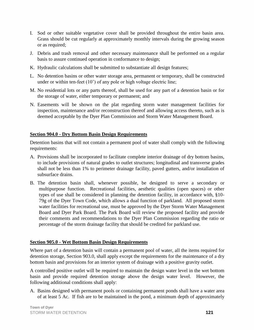
Town of Dyer
STORM WATER DETENTION 121
I. Sod or other suitable vegetative cover shall be provided throughout the entire basin area.
Grass should be cut regularly at approximately monthly intervals during the growing season
or as required;
J. Debris and trash removal and other necessary maintenance shall be performed on a regular
basis to assure continued operation in conformance to design;
K. Hydraulic calculations shall be submitted to substantiate all design features;
L. No detention basins or other water storage area, permanent or temporary, shall be constructed
under or within ten-feet (10’) of any pole or high voltage electric line;
M. No residential lots or any parts thereof, shall be used for any part of a detention basin or for
the storage of water, either temporary or permanent; and
N. Easements will be shown on the plat regarding storm water management facilities for
inspection, maintenance and/or reconstruction thereof and allowing access thereto, such as is
deemed acceptable by the Dyer Plan Commission and Storm Water Management Board.
Section 904.0 - Dry Bottom Basin Design Requirements
Detention basins that will not contain a permanent pool of water shall comply with the following
requirements:
A. Provisions shall be incorporated to facilitate complete interior drainage of dry bottom basins,
to include provisions of natural grades to outlet structures; longitudinal and transverse grades
shall not be less than 1% to perimeter drainage facility, paved gutters, and/or installation of
subsurface drains.
B. The detention basin shall, whenever possible, be designed to serve a secondary or
multipurpose function. Recreational facilities, aesthetic qualities (open spaces) or other
types of use shall be considered in planning the detention facility, in accordance with, §10-
79g of the Dyer Town Code, which allows a dual function of parkland. All proposed storm
water facilities for recreational use, must be approved by the Dyer Storm Water Management
Board and Dyer Park Board. The Park Board will review the proposed facility and provide
their comments and recommendations to the Dyer Plan Commission regarding the ratio or
percentage of the storm drainage facility that should be credited for parkland use.
Section 905.0 - Wet Bottom Basin Design Requirements
Where part of a detention basin will contain a permanent pool of water, all the items required for
detention storage, Section 903.0, shall apply except the requirements for the maintenance of a dry
bottom basin and provisions for an interior system of drainage with a positive gravity outlet.
A controlled positive outlet will be required to maintain the design water level in the wet bottom
basin and provide required detention storage above the design water level. However, the
following additional conditions shall apply:
A. Basins designed with permanent pools or containing permanent ponds shall have a water area
of at least 5 Ac. If fish are to be maintained in the pond, a minimum depth of approximately

Town of Dyer
STORM WATER DETENTION 122
ten feet (10’) shall be maintained over at least twenty-five percent (25%) of the pond area.
The remaining pond shall have no extensive shallow areas, except as required by Subsection
“C” below.
B. In excavated ponds, the underwater side slopes in the pond shall be stable. In the case of
valley storage, natural slopes may be considered to be stable.
C. A safety ledge four to six feet (4’ – 6’) in width is required and must be installed in all ponds
approximately thirty to thirty-six inches (30” – 36”) below the permanent water level. In
addition, a similar maintenance ledge twelve to eighteen inches (12” – 18”) above the
permanent water line shall be provided. The slope between the two (2) ledges shall be stable
and of a material such as stone or riprap which will prevent erosion due to wave action.
D. Retention ponds containing a permanent pool of water shall have all slopes between the
riprap and high water line sodded and the remaining land area hydro-seeded.
Ponds equipped with electrically driven aeration devices, if required to maintain proper
aerobic conditions and sustain aquatic life, shall have a four foot (4’) wide, crushed limestone
walkway at the high water line entirely around the body of water and shall provide suitable
public access acceptable to the Town.
The high water line shall not be closer than seventy-five feet (75’) to any property line.
E. Periodic maintenance is required in ponds to control weed and larval growth. The pond shall
also be designed to provide for the easy removal of sediment that will accumulate during
periods of pond operation. A means of maintaining the designed water level of the pond
during prolonged periods of dry weather is also required.
F. Amenities for emergency use, basin cleaning or shoreline maintenance shall be provided or
plans prepared for auxiliary equipment to permit emptying and drainage.
G. Facilities to enhance and maintain pond water quality shall be provided, if required the Board
of Storm Water Management or Director of Public Works, to meet applicable water quality
standards. Design calculations to substantiate the effectiveness of such aeration devices shall
be submitted with the Final Engineering Plans. Agreements for the perpetual operation and
maintenance of aeration devices shall be prepared to the satisfaction of the Board of Storm
Water Management after review and recommendation by the Plan Commission.
Section 906.0 - Parking Lot Storage
Paved parking lots may be designed to provide temporary detention storage of storm waters
under all or a portion of their surfaces. If paved parking lots are designed to provide temporary
storage of storm waters under all or a portion of their surfaces, then such design shall include
provision for subsurface detention systems, or other best available technology, to provide for the
following:
A. Capturing of settable solids, floatable and other debris;
B. Capturing of un-dissolved oils, grease, salts, gasoline, solvents, alcohols and other
hydrocarbons;

Town of Dyer
STORM WATER DETENTION 123
C. Ground water recharging by percolation of storm water back into the soil;
D. Control of effluent into the storm water collection system; and
E. Maintenance, repair and cleaning of the system.
Facilities for parking lot subsurface detention shall be designed to conform and comply with all
design requirements for the detention of storm water runoff, as set forth in this Section 900.0, et
seq., as amended. Ponding shall not be allowed in the paved parking areas to satisfy the design
requirements.
Section 907.0 - Facility Financial Responsibilities
The construction cost of storm water control systems and facilities as required by this Storm
Drainage Control Ordinance, as amended from time to time, shall be accepted as part of the cost
of land development.
Section 908.0 - Facility Maintenance Responsibility
Maintenance of detention/retention facilities, shall be the responsibility of the Town of Dyer,
only upon Final Acceptance by the Town of Dyer, and shall be determined and approved prior to
approval of the Final Engineering Plans.
Section 909.0 - Inspections
All public and privately owned detention storage facilities shall be inspected by the duly
designated representatives of the Town not less often than one (1) time every two years (2 yr).
A certified inspection report covering physical conditions, available storage capacity and
operational condition of key facility elements will be provided to the Owner.
Section 910.0 - Corrective Measures
If deficiencies are found by the Inspector, or duly designated representatives of the Town, the
Owner of the detention/retention facility will be required to take the necessary measures to
correct such deficiencies. If the Owner fails to correct such deficiencies, the Town will
undertake the work and collect from the Owner, using lien rights, as necessary.
Section 911.0 - Joint Development of Control Systems
Storm water control systems may be planned and constructed jointly by two (2) or more
developers as long as compliance with the Ordinance is maintained.
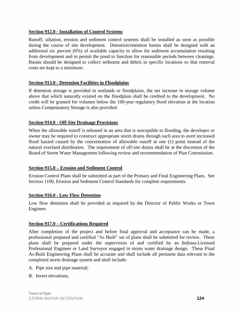
Town of Dyer
STORM WATER DETENTION 124
Section 912.0 - Installation of Control Systems
Runoff, siltation, erosion and sediment control systems shall be installed as soon as possible
during the course of site development. Detention/retention basins shall be designed with an
additional six percent (6%) of available capacity to allow for sediment accumulation resulting
from development and to permit the pond to function for reasonable periods between cleanings.
Basins should be designed to collect sediment and debris in specific locations so that removal
costs are kept to a minimum.
Section 913.0 - Detention Facilities in Floodplains
If detention storage is provided in wetlands or floodplains, the net increase in storage volume
above that which naturally existed on the floodplain shall be credited to the development. No
credit will be granted for volumes below the 100-year regulatory flood elevation at the location
unless Compensatory Storage is also provided.
Section 914.0 - Off-Site Drainage Provisions
When the allowable runoff is released in an area that is susceptible to flooding, the developer or
owner may be required to construct appropriate storm drains through such area to avert increased
flood hazard caused by the concentration of allowable runoff at one (1) point instead of the
natural overland distribution. The requirement of off-site drains shall be at the discretion of the
Board of Storm Water Management following review and recommendation of Plan Commission.
Section 915.0 – Erosion and Sediment Control
Erosion Control Plans shall be submitted as part of the Primary and Final Engineering Plans. See
Section 1100, Erosion and Sediment Control Standards for complete requirements.
Section 916.0 - Low Flow Detention
Low flow detention shall be provided as required by the Director of Public Works or Town
Engineer.
Section 917.0 – Certifications Required
After completion of the project and before final approval and acceptance can be made, a
professional prepared and certified “As Built” set of plans shall be submitted for review. These
plans shall be prepared under the supervision of and certified by an Indiana-Licensed
Professional Engineer or Land Surveyor engaged in storm water drainage design. These Final
As-Built Engineering Plans shall be accurate and shall include all pertinent data relevant to the
completed storm drainage system and shall include:
A. Pipe size and pipe material;
B. Invert elevations;
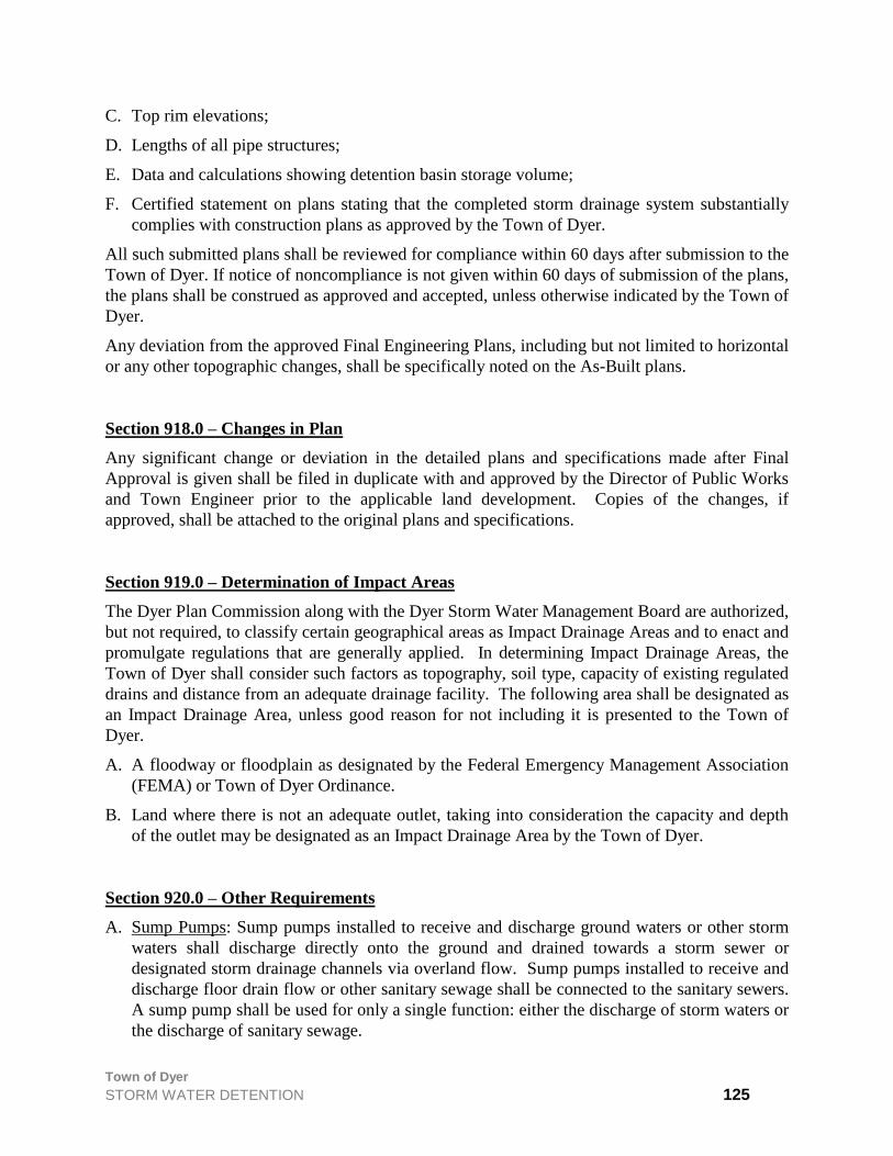
Town of Dyer
STORM WATER DETENTION 125
C. Top rim elevations;
D. Lengths of all pipe structures;
E. Data and calculations showing detention basin storage volume;
F. Certified statement on plans stating that the completed storm drainage system substantially
complies with construction plans as approved by the Town of Dyer.
All such submitted plans shall be reviewed for compliance within 60 days after submission to the
Town of Dyer. If notice of noncompliance is not given within 60 days of submission of the plans,
the plans shall be construed as approved and accepted, unless otherwise indicated by the Town of
Dyer.
Any deviation from the approved Final Engineering Plans, including but not limited to horizontal
or any other topographic changes, shall be specifically noted on the As-Built plans.
Section 918.0 – Changes in Plan
Any significant change or deviation in the detailed plans and specifications made after Final
Approval is given shall be filed in duplicate with and approved by the Director of Public Works
and Town Engineer prior to the applicable land development. Copies of the changes, if
approved, shall be attached to the original plans and specifications.
Section 919.0 – Determination of Impact Areas
The Dyer Plan Commission along with the Dyer Storm Water Management Board are authorized,
but not required, to classify certain geographical areas as Impact Drainage Areas and to enact and
promulgate regulations that are generally applied. In determining Impact Drainage Areas, the
Town of Dyer shall consider such factors as topography, soil type, capacity of existing regulated
drains and distance from an adequate drainage facility. The following area shall be designated as
an Impact Drainage Area, unless good reason for not including it is presented to the Town of
Dyer.
A. A floodway or floodplain as designated by the Federal Emergency Management Association
(FEMA) or Town of Dyer Ordinance.
B. Land where there is not an adequate outlet, taking into consideration the capacity and depth
of the outlet may be designated as an Impact Drainage Area by the Town of Dyer.
Section 920.0 – Other Requirements
A. Sump Pumps: Sump pumps installed to receive and discharge ground waters or other storm
waters shall discharge directly onto the ground and drained towards a storm sewer or
designated storm drainage channels via overland flow. Sump pumps installed to receive and
discharge floor drain flow or other sanitary sewage shall be connected to the sanitary sewers.
A sump pump shall be used for only a single function: either the discharge of storm waters or
the discharge of sanitary sewage.

Town of Dyer
STORM WATER DETENTION 126
B. Down Spouts: All down spouts or roof drains shall discharge directly onto the ground and
drained towards a storm sewer or designated storm drainage channels via overland flow. No
down spouts or roof drains shall be connected to the sanitary sewers.
C. Footing Drains: Footing drains shall discharge directly onto the ground and drained towards a
storm sewer or designated storm drainage channels via overland flow. No footing drains or
drainage tile shall be connected to the sanitary sewer.
D. Basement Floor Drains: Basement floor drains shall be connected to the sanitary sewers.
Section 921.0 – Disclaimer of Liability
The degree of protection required by this ordinance is considered reasonable for regulatory
purposes and is based on historical records, engineering and scientific methods of study. Larger
storms may occur or storm water runoff depths may be increased by man-made or natural causes.
This ordinance does not imply that land uses permitted will be free from storm water damage.
This ordinance shall not create liability on the part of Town of Dyer or any board, department,
office, official, agent, or employee for any damage which may result from reliance on this
ordinance or on any administrative decision lawfully made there under.
Section 922.0 – Corrective Action
Nothing herein contained shall prevent the Town of Dyer from taking such lawful action as may
be necessary to prevent or remedy any violation of this Ordinance. All costs connected therewith
shall accrue to the person or persons responsible.
Section 923.0 – Repealed
All ordinances or parts thereof in conflict with the provisions of this Ordinance are repealed.
Section 924.0 – When Effective
This Ordinance shall become effective after its final passage, approval and publication as
required by law.
Section 925.0 – Exempt Projects
All residential, commercial or industrial subdivision (major or minor) or construction project
thereon, which has had its drainage plan approved by the Dyer Plan Commission prior to the
effective date of this Ordinance, shall be exempt from all of the requirements of this Ordinance.

Town of Dyer
ENGINEERING DRAWING STANDARDS 127
ENGINEERING DRAWING STANDARDS
Section 1000.0 - Requirements of Primary Engineering Plans
Primary Engineering shall be of the form of exhibits portraying engineering concepts, and a
limited amount of design engineering. The exhibits shall delineate the areas earmarked for
detention/retention, park and school donation. There shall be on the plans, street and cul-de-sac
geometric layout and the layout of sanitary and storm sewers and water mains. The sizes of
various utilities and location of the related appurtenances need not be included in the preliminary
engineering plans; however, elevations of sewers at important locations are desirable.
If any variance from the standard requirements is desired or planned, it should be clearly noted
on the preliminary plan.
The plan size shall be thirty six by twenty four inches (36”x 24”) and be drawn to a suitable scale
providing maximum convenience in its review. The other information that is necessary to be
shown on the plans is the location sketch, title of the improvement, the engineering firm
responsible for plan preparation.
The contour and spot elevations shown on the plans shall be with reference to the U.S.G.S.
Systems.
The Primary Engineering Plans prepared for all public improvement or subdivision
improvements shall be of the size not more or less than 36”x 24”, drawn legibly containing all
the pertinent information that is necessary for complete review and field construction of the
facility or improvement proposed.
All plans shall be signed & sealed by the design professional.
Section 1001.0 - Required Submittals For Primary Engineering
Section 1002.0 - Title Sheet:
The front sheet of any engineering plans should include informative items such as the title of
project, name(s) of the engineering firms(s) responsible for the plan preparation, the owners(s),
locations sketch, index of sheets, general notes, benchmarks, dates and the engineer's seal and
signature. Each revision should be identified with dates and a short description or note about the
nature of the revision.
Section 1002.1 - Utility Plans
In the subdivision plans, the first few sheets named as utility sheets shall illustrate the proposed
utilities in the subdivision including the off-site utility extensions. The scale of such utility plans
shall be conveniently chosen by the designer, but in no event smaller than one inch equal to fifty
feet (1”=50’). There shall be three utility plans in any one set of subdivision plans; for each of
the following utility systems:
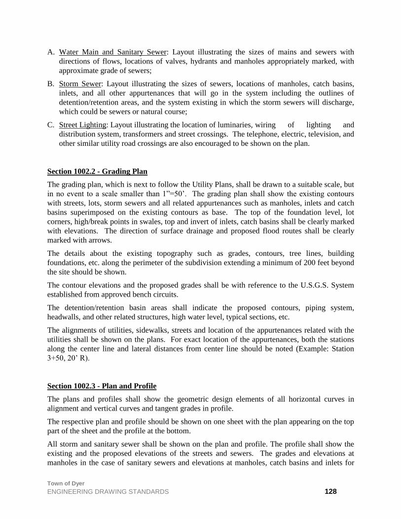
Town of Dyer
ENGINEERING DRAWING STANDARDS 128
A. Water Main and Sanitary Sewer: Layout illustrating the sizes of mains and sewers with
directions of flows, locations of valves, hydrants and manholes appropriately marked, with
approximate grade of sewers;
B. Storm Sewer: Layout illustrating the sizes of sewers, locations of manholes, catch basins,
inlets, and all other appurtenances that will go in the system including the outlines of
detention/retention areas, and the system existing in which the storm sewers will discharge,
which could be sewers or natural course;
C. Street Lighting: Layout illustrating the location of luminaries, wiring of lighting and
distribution system, transformers and street crossings. The telephone, electric, television, and
other similar utility road crossings are also encouraged to be shown on the plan.
Section 1002.2 - Grading Plan
The grading plan, which is next to follow the Utility Plans, shall be drawn to a suitable scale, but
in no event to a scale smaller than 1”=50’. The grading plan shall show the existing contours
with streets, lots, storm sewers and all related appurtenances such as manholes, inlets and catch
basins superimposed on the existing contours as base. The top of the foundation level, lot
corners, high/break points in swales, top and invert of inlets, catch basins shall be clearly marked
with elevations. The direction of surface drainage and proposed flood routes shall be clearly
marked with arrows.
The details about the existing topography such as grades, contours, tree lines, building
foundations, etc. along the perimeter of the subdivision extending a minimum of 200 feet beyond
the site should be shown.
The contour elevations and the proposed grades shall be with reference to the U.S.G.S. System
established from approved bench circuits.
The detention/retention basin areas shall indicate the proposed contours, piping system,
headwalls, and other related structures, high water level, typical sections, etc.
The alignments of utilities, sidewalks, streets and location of the appurtenances related with the
utilities shall be shown on the plans. For exact location of the appurtenances, both the stations
along the center line and lateral distances from center line should be noted (Example: Station
3+50, 20’ R).
Section 1002.3 - Plan and Profile
The plans and profiles shall show the geometric design elements of all horizontal curves in
alignment and vertical curves and tangent grades in profile.
The respective plan and profile should be shown on one sheet with the plan appearing on the top
part of the sheet and the profile at the bottom.
All storm and sanitary sewer shall be shown on the plan and profile. The profile shall show the
existing and the proposed elevations of the streets and sewers. The grades and elevations at
manholes in the case of sanitary sewers and elevations at manholes, catch basins and inlets for

Town of Dyer
ENGINEERING DRAWING STANDARDS 129
storm sewers shall appear in profile. It is not necessary to show water mains in profile except at
locations of elevation conflicts wherein methods of overcoming such conflicts shall be shown in
the profile.
Section 1002.4 - Construction Details
The details on the set of the engineering plans shall show the construction details of the various
utilities and the related appurtenances, typical sections of pavements, curbs, sidewalks, special
structures that will be built in detention/retention basins, ditch section, rip-rap, etc., and further it
shall include the details and shop drawings of items that are required by the Town.
Section 1002.5 – Erosion and Sediment Control
Erosion Control Plans shall be submitted as part of the Primary and Final Engineering Plans. See
Section 1100, Erosion and Sediment Control Standards for complete requirements.
Section 1003.0 - As-Built Drawings
Any significant change or deviation in the detailed engineering plans and specifications made
after Final Approval is given shall be filed in duplicate with and approved by the Director of
Public Works and Town Engineer prior to the applicable land development. Copies of the
changes, if approved, shall be attached to the original plans and specifications.
It shall be the responsibility of the Developer to ensure that the Design Engineer or Consultant
revise or update the engineering plans as necessary as changes occur at the time of field
construction to fit to the unusual field conditions or as dictated by economical consideration.
After completion of the Construction of Public Improvements, the Developer shall submit the
original set of As-Built drawings to the Director of Public Works (Town Engineer shall receive a
copy of As-Builts) and such drawings shall remain in the Town custody. The originals shall be
no less than of good quality mylar, capable of reproducing clear and good quality prints.
Such as-built drawings shall be completed with cover sheet, general and specific notes, and detail
sheets incorporating all field changes affected because of field discoveries other than anticipated.
The plans shall clearly show all grades of streets, sidewalk, lot corners, foundations, pipe sizes,
alignments of streets and utilities, water and sanitary service locations, sanitary sewer, wye or tee
locations measured from downstream manholes, measurements of pipe between manholes, rims
and inverts, any additions or deletions, etc. The As-Built Drawings shall be signed and sealed by
the Design Engineer. Submittals by various contractors will not be acceptable.
In addition to any other forms of submittal required elsewhere in this Ordinance, the Developer
shall provide the Town all Primary and Secondary Plats as well as the aforementioned As-Built
Engineering Drawings in electronic format, specifically in the most current or previous version of
the AutoDesk AutoCAD® software drawing format. The submittal shall be provided to the
Town in a standard form of magnetic or optical media that is compatible with the Town’s

Town of Dyer
ENGINEERING DRAWING STANDARDS 130
information system. Alternate drawing formats or means of submittal may be accepted upon
prior approval from the Town of Dyer’s Director of Public Works.
Section 1004.0 - Miscellaneous Requirements
The other requirements that should accompany the Final Engineering Plans include the Plat of
Subdivision depicting the various easements as required by the Town of Dyer for the purpose of
protection and maintenance of public utilities and drainage ways; Design Engineer's Estimate of
Cost of all Public Improvements; and all engineering calculations that have been used for design
of specific improvements such as detention/retention or storm sewers. Any other pertinent
information such as soil investigation, traffic projection, etc., if required or available, should be
submitted with the plans.
Section 1005.0 - Standards
The construction of various Public Improvements shall follow the Town of Dyer Standards,
Section 1100, in size, shape, materials, and pattern. Any items of improvement, which are not
covered in the Standards, shall be submitted to the Director of Public Works and Town Engineer
for special consideration and approval.

Town of Dyer
ENGINEERING DRAWING STANDARDS 131
EROSION AND SEDIMENT CONROL STANDARDS
Section 1100.0 – Permit for Installation of Erosion and Sediment control Systems:
Erosion and Sediment Control Plans shall be submitted to the Plan Commission as part of the
construction plans and specifications and shall include the following:
A. Temporary erosion and sediment control measures necessary prior to and during the initial
construction and establishment phases up to final site grading and seeding.
B. A permanent erosion and sediment control plan of all the graded and non-hard surface areas
within the proposed development, as planned for completion, up to and including seeding of
the final lot on which business or residential dwellings are to be place.
C. Details concerning removal of temporary erosion control devices after the initial
establishment of adequate vegetative cover.
D. Maintenance procedures as part of the continuing plan to keep all of the land under adequate
cover and erosion at an acceptable minimum.
E. All erosion control measures, including, but not limited to, those required to comply with the
ordinance, shall meet the design criteria, standards and specifications for erosion control
measures similar to or the same as those outlined in the most recent edition of the Indiana
Handbook for Erosion Control in Developing Areas.
F. No person shall be granted primary plat approval for a parcel of real property having an area
of 2,500 or more square feet without the approval of an erosion and sediment control plan by
the Town of Dyer Plan Commission.
G. Each plan shall bear the names and addresses of the owner and/or developer of the site, and
of any consulting firm retained by the applicant together with the name of the applicant’s
principal contact at such firm.
H. Each plan shall include a statement that any land clearing, construction, or development
involving the movement of earth shall be in accordance with the erosion and sediment control
plan.
Section 1100.1 – Review and Approval
The Town of Dyer Plan Commission shall review each application for plat of subdivision and
Erosion and Sediment Control Plan to determine its conformance with the provisions of this
Ordinance.
Section 1101.0 – Erosion and Sediment Control Plan
A. The Erosion and Sediment Control Plan shall include the following:
1. A sequence of construction of the development site, including stripping and clearing;
rough grading; construction of utilities, infrastructure, and the expected date on which

Town of Dyer
ENGINEERING DRAWING STANDARDS 132
clearing will begin, the estimated duration of exposure of cleared areas, areas of clearing,
installation of temporary erosion and sediment control measures, and establishment of
permanent vegetation.
2. All erosion and sediment control measures necessary to meet the objectives of this local
regulation throughout all phases of construction and after completion of development of
the site. Depending upon the complexity of the project, the drafting of intermediate plans
may be required at the close of each season.
3. Seeding mixtures and rates, types of sod, method of seedbed preparation, expected
seeding dates, type and rate of lime and fertilizer application, and kind and quantity of
mulching for both temporary and permanent vegetative control measures.
4. Provisions for maintenance of control facilities, including easements and estimates of the
cost of maintenance.
B. Modifications to the plan shall be processed and approved or disapproved in the same manner
described above and may be authorized by the Town of Dyer Plan Commission by written
authorization, and shall include:
1. Major amendments of the erosion and sediment control plan submitted to the Town of
Dyer Plan Commission; and
2. Field modifications of a minor nature.
Section 1102.0 – Design Requirements
A. Grading, erosion control practices, sediment control practices, and waterway crossings shall
meet the design criteria set forth herein, and shall be adequate to prevent transportation of
sediment from the site to the satisfaction of the Town of Dyer Plan Commission. Cut and fill
slopes shall be no greater than 2:1, except as approved by the Town of Dyer Plan
Commission to meet other community or environmental objectives.
B. Clearing and grading of natural resources, such as forests and wetlands, shall not be
permitted, except when in compliance with all other chapters of this Subdivision Control
Ordinance. Clearing techniques that retain natural vegetation and drainage patterns, as
described herein, shall be used to the satisfaction of the Town of Dyer Plan Commission.
C. Clearing, except that necessary to establish sediment control devices, shall not begin until all
sediment control devices have been installed and have been stabilized.
D. Erosion control requirements shall include the following:
1. Soil stabilization shall be completed within five (5) days of clearing or inactivity in
construction.
2. If seeding or another vegetative erosion control method is used, it shall become
established within two (2) weeks or the Town of Dyer Plan Commission may require the
site to be reseeded or a non-vegetative option employed.
3. Special techniques that meet the design criteria outlined herein on steep slopes or in
drainage ways shall be used to ensure stabilization.

Town of Dyer
ENGINEERING DRAWING STANDARDS 133
4. Soil stockpiles must be stabilized or covered at the end of each workday.
5. The entire site must be stabilized, using a heavy mulch layer or another method that does
not require germination to control erosion, at the close of the construction season.
6. Techniques shall be employed to prevent the blowing of dust or flow of sediment from
the site.
7. Techniques that divert upland runoff past disturbed slopes shall be employed.
E. Sediment controls requirements shall include:
1. Settling Basins – A settlement basin is an impoundment with a controlled storm water
release structure for the purpose of detaining runoff to allow excessive sediment to settle.
Settlement basins shall be required at the outlet of any disturbed areas with major grading
that are larger than ten (10) acres. The minimum volume of a sediment basin shall be
sixty-seven (67) cubic yards per acre for the total drainage area, measured below the top
of principal spillway or riser. The cleanout volume shall be not less than one-quarter
(1/4) nor more than one-third (1/3) of the total storage volume of a sediment basin.
Maximum slopes shall be 2:1 (H:V) for excavated areas and for compacted
embankments. Side slopes shall be 3:1 (H:V) or flatter, which will allow people and
equipment to safely negotiate slopes or to enter the sediment basin for maintenance and
repair purposes. The length to width ratio must be greater than 2:1 (L:W) for the
principal flow-paths in order to maximize residence time of storm water within the
sediment basin. The principal outlet or spillway should be sized to adequately convey
storm water runoff from the two (2) year, twenty-four (24) hour storm.
2. Sediment traps – A sediment trap is a small temporary pond that drains a disturbed area
so that sediment can settle out. Sediment traps shall be required for any disturbed area
which is greater than one (1) acre and less than five (5) acres. The minimum volume of a
sediment trap shall be sixty-seven (67) cubic yards per acre for the total drainage area.
The outlet structure shall consist of layers of aggregate, rock or riprap material. The
cleanout volume shall be not less than one-quarter (1/4) nor more than one-third (1/3) of
the total storage volume of a sediment basin. Maximum slopes shall be 2:1 (H:V) for
excavated areas and for compacted embankments. Side slopes shall be 3:1 (H:V) or
flatter, which will allow people and equipment to safely negotiate slopes or to enter the
sediment basin for maintenance and repair purposes. The length to width ratio must be
greater than 2:1 (L:W) for the principal flow-paths in order to maximize residence time of
storm water within the sediment basin. An emergency overflow weir should be provided
at an elevation of at least one and one-half feet (1.5’) below the top of embankment, with a
minimum freeboard of one foot (1’).
3. Silt fences - Silt fencing shall be required on all disturbed areas and shall be constructed
pursuant to the following standards:
a. Install silt fence at level grade parallel to the contour of the land; extend ends
upslope to allow water to pond behind fence; excavate a trench four inches (4”)
wide, eight inches (8”) deep; install fence with posts on the down slope side; place

Town of Dyer
ENGINEERING DRAWING STANDARDS 134
twelve inches (12”) of fabric in the trench, extending the bottom four inches (4”)
toward the upslope side; join silt fence sections by using a wrap joint; backfill
trench with soil materials and compact; inspect at least weekly and after each
storm event, repairing as needed and removing sediment deposits when they reach
one-half (1/2) the fence height.
b. The maximum drainage area to the silt fence shall be one-half (0.5) acre or less
per one hundred feet (100’) of fence. Silt fencing shall not be used in live or
continuously flowing streams or channels and shall not be used in ditches or
swales which drain areas greater than one (1) acre. Silt fences shall not be used in
steep ditches or swales where the design flow is greater than two feet (2’) per
second.
c. Silt fencing fabric shall be comprised of synthetic filter fabric manufactured from
woven or non-woven sheets of polypropylene, nylon or polyester. Typical
properties for silt fencing fabric shall be as follows:
tensile strength at 20% elongation: 50 pounds per linear inch
burst strength: 180 psi
trapezoidal tear strength: 50 pounds
apparent opening size: 20 to 30 (US sieve size)
flow rate: 0.30 gallons per minute per square foot
d. The maximum length of silt fence between posts is eight feet (8’). Wood posts
shall have a minimum dimension of two inches (2”) x two inches (2”) for hard
woods (i.e. oak) and three inches (3”) x three inches (3”) for soft woods (i.e.
pine). Typical post length shall be forty-eight inches (48”). There shall be a
minimum of five (5) fasteners for each wood post.
e. The maximum slope lengths for silt fence installations shall be as follows:
Land Slope Maximum Slope Length
Less than 2% 100 feet
From 2% to 5% 75 feet
From 5% to 10% 50 feet
From 10% to 20% 25 feet
More than 20% 15 feet
4. Protection for adjacent properties by the use of a vegetated buffer strip in combination
with perimeter controls.
5. Installation and maintenance of drop inlet protection devices, utilizing either of the
following techniques:

Town of Dyer
ENGINEERING DRAWING STANDARDS 135
a. Silt Fence - Construct a six inch (6”) dike on the down slope side to prevent
bypass flow; dig a trench eight inches (8”) deep and four inches (4”) wide; space
support posts evenly against the inlet perimeter a maximum of four feet (4’) apart
and drive them one and one-half feet (1.5’) into the ground; use enough fabric
from a single roll to eliminate joints and using lath and nails, fasten fabric to the
posts; place twelve inches (12”) of fabric in the trench, extending the bottom four
inches (4”) toward the upslope side; join silt fence sections by using a wrap joint;
backfill the trench with soil materials and compact; cross brace the corners to
prevent collapse of the structure; inspect at least weekly and after each storm
event, and repair as needed, and remove accumulated sediments after every storm.
b. Placement of a pre-manufactured drop inlet protection device around the inlet
perimeter, having at least the same design characteristics set forth in the preceding
paragraph.
c. Block and Gravel – Place concrete blocks lengthwise on their sides in a single row
around the perimeter of the inlet, so that the open ends face outward and not
upward. Ends of adjacent blocks should abut. The height of the barrier can be
varied by stacking combinations of blocks that are typically six (6) or eight (8)
inches high. Place geotextile filter fabric over the outside vertical face of the
concrete blocks. If more than one strip is necessary, overlap the strips by at least
one foot (1’). Place clean stone against the geotextile filter fabric up to the top of
the concrete blocks. Use one-half inch (1/2”) to three-quarter inch (3/4”) gravel.
F. Waterway and watercourse protection requirements shall include:
1. A temporary stream crossing installed and approved by the Town of Dyer Plan
Commission if a wet watercourse will be crossed regularly during construction.
2. Stabilization of the watercourse channel before, during, and after any in-channel work.
3. All on-site storm water conveyance channels designed according to the criteria outlined
herein.
4. Stabilization adequate to prevent erosion located at the outlets of all pipes and paved
channels.
G. Construction site access requirements shall include:
1. A temporary site access road provided at all sites, unless the Town of Dyer Plan
Commission determines that such temporary access road is not necessary. Such
temporary site access road shall be constructed pursuant to the following standards:
Place six inches (6”) of course aggregate (INDOT CA No. 2) over a stable sub
grade;
Construct the road at least twelve feet (12’) wide and fifty feet (50’) long or the
distance of the foundation;
Add stone as needed to maintain six inches (6”) of clean depth.

Town of Dyer
ENGINEERING DRAWING STANDARDS 136
2. Other measures required by the Town of Dyer Plan Commission in order to ensure that
sediment is not tracked onto public streets by construction vehicles or washed into storm
drains.
Section 1103.0 – Inspection
A. The Town of Dyer Plan Commission shall make inspections as hereinafter required and either
shall approve that portion of the work completed or shall notify the owner of developer
wherein the work fails to comply with the Erosion and Sediment Control Plan as approved.
Plans for grading, stripping, excavating, and filling work bearing the stamp of approval of the
Town of Dyer Plan Commission shall be maintained at the site during the progress of the
work. To obtain inspections, the owner or developer shall notify the Town of Dyer Plan
Commission at least two (2) working days before the following:
1. Start of construction.
2. Installation of sediment and erosion measures.
3. Completion of site clearing.
4. Completion of rough grading.
5. Completion of final grading.
6. Close of the construction season.
7. Completion of final landscaping.
B. The owner or developer or his/her agent shall make regular inspections of all control
measures in accordance with the inspection schedule outlined on the approved Erosion and
Sediment Control Plan, as approved. The purpose of such inspections will be to determine
the overall effectiveness of the control plan and the need for additional control measures. All
inspections shall be documented in written form and submitted to the Town of Dyer Plan
Commission, or their designated town employee(s) or agent(s) at the time interval specified.
C. The Town of Dyer Plan Commission, or their designated town employee(s) or agent(s), shall
enter the property of the applicant as deemed necessary to make regular inspections to ensure
the validity of the reports filed by the owner of developer.

Town of Dyer
STANDARD DRAWINGS 137
STANDARD DRAWINGS
Section 1200.0 - List of Figures:
Engineering Notes
Section 1200.1 - List of Tables:
Restrained Pipe Length Table
Section 1200.2 - List of Dyer Standard Drawings:
1. Pipe Bedding Detail for Trench in Grass Areas
2. Pipe Bedding Detail for Trench in Paved Areas
3. Trench Paving Section for Asphaltic Concrete Surface
4. Standard Inlet
5. Storm Sewer Manhole Type “A”
6. Subsurface Drain Detail
7. Type “A” Catch Basin
8. Type “B” Manhole
9. Type “C” (Flat Top) Manhole
10. Casting Adjustment
11. Casing Detail
12. Cleanout Detail
13. Exterior Drop Manhole
14. Type “A” Sanitary Manhole
15. Typical Pipe Concrete Encasement
16. Typical Riser For Sanitary Service Lateral
17. Air Release Manhole
18. Fire Hydrant Assembly
19. Fire Hydrant Assembly Type “B”
20. Main Line Water Valve
21. Public Utility Service Connection
22. Typical Copper Water Service
23. Thrust Block Installations
24. Residential Arterial Street
25. Residential Collectors
26. Typical Curb Details
27. Typical Pavement Section
28. Temporary Construction Entrance

Town of Dyer
STANDARD DRAWINGS 138
Section 1200.3 - List of INDOT Standard Drawings:
29. Temporary Silt Fence
30. Temporary Interceptor Ditch
31. Temporary Slope Drain, Plan and Elevation
32. Temporary Slope Drain, Isometric
33. Temporary Ditch Inlet Protection, Gravel Ring
34. Temporary Ditch Inlet Protection, Geotextile Box
35. Temporary Ditch Inlet Protection, Slotted Barrel
36. Temporary Check Dam, Revetment Riprap
37. Temporary Check Dam, Straw Bales
38. Temporary Sediment Trap